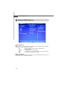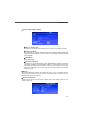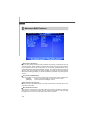
1
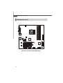
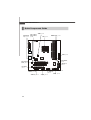
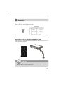
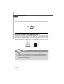
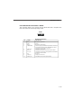
MS-7304 (V1.X) Mainboard
i
Copyright Notice
T he material in this doc ument is the intellec tual property of M ICRO-STAR
INTERNATIONAL. We take every care in the preparation of this document, but no
guarantee is given as to the correctness of its contents. Our products are under
continual improvement and we reserve the right to make changes without notice.
Trademarks
All trademarks are the properties of their respective owners.
Intel® and Pentium® are registered trademarks of Intel Corporation.
AMD, Athlon™, Athlon™ XP, Thoroughbred™, and Duron™ are registered trademarks of AMD Corporation.
NVIDIA, the NVIDIA logo, DualNet, and nForce are registered trademarks or trademarks of NVIDIA Corporation in the United States and/or other countries.
PS/2 and OS ® /2 are registered trademarks of International Business Machines
Corporation.
W indows ® 95/98/2000/NT/XP are registered trademarks of Microsoft Corporation.
Netware® is a registered trademark of Novell, Inc.
Award® is a registered trademark of Phoenix Technologies Ltd.
AMI® is a registered trademark of American Megatrends Inc.
Revision History
Revision
Revision History
Date
V1.0
First release
February 2008
Technical Support
If a problem arises with your system and no solution can be obtained from the user’s
manual, please contact your place of purchase or local distributor. Alternatively,
please try the following help resources for further guidance.
Vis i t the MSI webs ite at http ://glob al.msi. com.tw /index. php?
func=faqIndex for FAQ, technical guide, BIOS updates, driver updates,
and other information.
Contact our technical staff at http://support.msi.com.tw/.
ii
Safety Instructions
1.
Always read the safety instructions carefully.
2.
Keep this User’s Manual for future reference.
3.
Keep this equipment away from humidity.
4.
Lay this equipment on a reliable flat surface before setting it up.
5.
The openings on the enclosure are for air convection hence protects the equipment from overheating. DO NOT COVER THE OPENINGS.
6.
Make sure the voltage of the power source and adjust properly 110/220V before connecting the equipment to the power inlet.
7.
Place the power cord such a way that people can not step on it. Do not place
anything over the power cord.
8.
Always Unplug the Power Cord before inserting any add-on card or module.
9.
All cautions and warnings on the equipment should be noted.
10. Never pour any liquid into the opening that could damage or cause electrical
shock.
11. If any of the following situations arises, get the equipment checked by service
personnel:
The power cord or plug is damaged.
Liquid has penetrated into the equipment.
The equipment has been exposed to moisture.
The equipment does not work well or you can not get it work according to
User’s Manual.
The equipment has dropped and damaged.
The equipment has obvious sign of breakage.
12. DO NOT LEAVE THIS EQUIPMENT IN AN ENVIRONMENT UNCONDITIONED, STORAGE TEMPERATURE ABOVE 600 C (1400F), IT MAY DAMAGE THE EQUIPMENT.
CAUTION: Danger of explosion if battery is incorrectly replaced.
Replace only with the same or equivalent type recommended by
the manufacturer.
iii
FCC-B Radio Frequency Interference Statement
T h is eq uip men t h as been
tested and found to c omply
with the limits for a Class B
digital device, pursuant to Part
15 of the FCC Rules. These limits are designed to provide reasonable protection
against harmful interference in a residential installation. This equipment generates,
uses and can radiate radio frequency energy and, if not installed and used in accordance with the instructions, may cause harmful interference to radio communications.
However, there is no guarantee that interference will not occur in a particular
installation. If this equipment does cause harmful interference to radio or television
reception, which can be determined by turning the equipment off and on, the user is
encouraged to try to correct the interference by one or more of the measures listed
below.
Reorient or relocate the receiving antenna.
Increase the separation between the equipment and receiver.
Connect the equipment into an outlet on a circuit different from that to
which the receiver is connected.
Consult the dealer or an experienced radio/television technician for help.
Notice 1
The changes or modifications not expressly approved by the party responsible for
compliance could void the user’s authority to operate the equipment.
Notice 2
Shielded interface cables and A.C. power cord, if any, must be used in order to
comply with the emission limits.
VOIR LA NOTICE D’INSTALLATION AVANT DE RACCORDER AU RESEAU.
Micro-Star International
MS-7304
This device complies with Part 15 of the FCC Rules. Operation is subject to the
following two conditions:
(1) this device may not cause harmful interference, and
(2) this device must accept any interference received, including interference that
may cause undesired operation.
iv
WEEE (Waste Electrical and Electronic Equipment) Statement
v
vi
vii
CONTENTS
Copyright Notice .............................................................................................................. ii
Trademarks ....................................................................................................................... ii
Revision History .............................................................................................................. ii
Technical Support ........................................................................................................... ii
Safety Instructions ......................................................................................................... iii
FCC-B Radio Frequency Interference Statement ........................................................ iv
W EEE (Waste Electrical and Electronic Equipment) Statement .................................... v
Chapter 1 Getting Started ..................................................................................... 1-1
Mainboard Specifications ................................................................................... 1-2
Mainboard Layout ................................................................................................ 1-4
Chapter 2 Hardware Setup .................................................................................... 2-1
Quick Components Guide .................................................................................... 2-2
CPU (Central Processing Unit) ............................................................................ 2-3
Memory ................................................................................................................. 2-6
Power Supply ...................................................................................................... 2-8
Back Panel ............................................................................................................ 2-9
Connector ........................................................................................................... 2-11
Slot ...................................................................................................................... 2-16
Jumper ................................................................................................................ 2-17
Chapter 3 BIOS Setup ............................................................................................. 3-1
Entering Setup ..................................................................................................... 3-2
The Main Menu ..................................................................................................... 3-4
Standard CMOS Features ................................................................................... 3-6
Advanced BIOS Features ................................................................................... 3-8
Integrated Peripherals ........................................................................................ 3-11
Power Management Setup ............................................................................... 3-13
PNP/PCI Configurations ..................................................................................... 3-15
H/W Monitor ........................................................................................................ 3-17
Frequency/Voltage Control ............................................................................... 3-18
Load Fail-Safe / Optimized Defaults ................................................................ 3-21
Set Supervisor Password ................................................................................ 3-22
viii
Getting Started
Chapter 1
Getting Started
Thank you for choosing the MS-7304 v1.X Micro-ATX
mainboard. The MS-7304 is based on AMD® RS780 &
SB700 chipsets for optimal system efficiency. Designed
to fit the advanced AMD® Athlon64 / Athlon64 X2 / AM2+
processors in Socket AM2/ AM2+, the MS-7304 delivers a high performance and professional desktop platform solution.
1-1
M S-7304 M ainboard
Mainboard Specifications
Proce ssor
- Supports AMD Athlon64 / Athlon64 X2 /AM2+ processors
- Supports 4-pin CPU fan pinheader with Fan Speed Control
- Supports up to 5000+ and above
FSB
- Hyper Transport supports up to 3.0GHz
Chipset
- North Bridge: AMD RS780
- South Bridge: AMD SB700
M e mo r y
- DDR2 533/667/800/1066 SDRAM (240 pins / 1.8V)
- 4 DDR2 DIMM slots (8GB Max)
LAN
- Gigabit Fast Ethernet by Realtek RTL8111C
IEEE 1394
- Chip integrated by JMicron 381
- Transfer rate is up to 400MB/s
Audio
- Chip integrated by Realtek ALC888S
- Flexible 8-channel audio with jack sensing
- Com pliant with Azalia 1.0 Spec
SATA
- SATA II ports by SB700
- Supports 4 SATA II devices
- Supports storage and data transfers at up to 300MB/s
1-2
Getting Started
Connectors
Back Panel
- 1 SPDIF-out port
- 1 DVI port
- 1 IEEE 1394 port
- 6 USB 2.0 ports
- 1 Gigabit LAN jack
- 6 flexible audio jacks
Onboard Connectors
- 2 USB 2.0 connectors (4 ports)
- 1 IEEE 1394 connector
- 1 SPDIF-out connector
- 1 front panel connector
- 1 front panel audio connector
Slots
- 1 PCI Express x16 slot
- 1 PCI Express x1 slot
- 2 32-bit/33MHz PCI slots
Form Factor
- M-ATX (24.4cm X 24.4 cm)
M ounting
- 8 mounting holes
1-3
M S-7304 M ainboard
Mainboard Layout
CPU_FAN1
JSPDO2
DVI Port
AT X 1
USB Ports
Top: 1394 Port
Bottom: USB Ports
Top: LAN Jack
Bottom: USB Ports
T: Line-In
M: Line-Out
B: Mic
T: R S-Out
M: CS-Out
B: SS-Out
AUX_FAN1
JPW1
D IM M 4
D IM M 3
D IM M 1
D IM M 2
AMD
RS780
PCI E1_X1
BATT
+
PCI E16_X1
PCI 1
F_U SB2
S ATA 4
Audio C hip
S AT A 1
PCI 2
S ATA 2
AMD
SB700
S ATA 3
CLR_CMOS1
LA N Chip
F_U SB1
JAUD 1 JSPDO1
J1394
JSPI1
MS-7304 (v1.X) Micro-ATX Mainboard
1-4
JFP1
Hardware Setup
Chapter 2
Hardware Setup
This chapter provides you with the information about
hardware setup procedures. While doing the installation,
be careful in holding the components and follow the
installation procedures. For some components, if you
install in the wrong orientation, the components will not
work properly.
Use a grounded wrist strap before handling computer
c om ponen ts . S tatic elec tric ity m ay damage the
components.
2-1
M S-7304 M ainboard
Quick Components Guide
Back Panel
I/O, p.2-9
CPU _FAN 1,
AUX_FAN1,
p.2-12
JPW1, p.2-8
DIMM Slots, p.2-6
CPU, p.2-3
ATX1, p.2-8
BATT
+
CLR_CMOS1,
p.2-16
PCI Express
Slots, p.2-17
SATA1~4,
p.2-11
PCI Slots,
p.2-17
JAUD1, p.2-13
JSPDO1, p.2-12
2-2
F_USB1~2,
p.2-14
J1394, p.2-14
JFP1, p.2-15
JSPI1, p.2-11
Hardware Setup
CPU (Central Processing Unit)
The mainboard supports AMD ® Athlon64 / Athlon64 X2 / AM2+ processors in Socket
AM2/ AM2+. The Socket AM2/ AM2+ offers easy CPU installation. W hen you are
installing the CPU, make sure the CPU has a heat sink and a cooling fan
attached on the top to prevent overheating. If you do not have the heat sink and
cooling fan, contact your dealer to purchase and install them before turning on the
computer.
For the latest information about CPU, please visit http://global.msi.com.tw/index.
php?func=cpuform.
Important
Overheating
Overheating will seriously damage the CPU and system. Always make sure
the cooling fan can work properly to protect the CPU from overheating. Make
sure that you apply an even layer of thermal paste (or thermal tape) between
the CPU and the heatsink to enhance heat dissipation.
Replacing the CPU
While replacing the CPU, always turn off the power supply or unplug the
power supply’s power cord from the grounded outlet first to ensure the safety
of CPU.
2-3
M S-7304 M ainboard
CPU Installation Procedures for Socket AM2/ AM2+
1. Please turn off the power and
unplug the power cord before
installing the CPU.
2. Pull the lever s ideways away
from the socket. Make sure that
you raise the lever up to a 90degree angle.
3. Look for the gold arrow on the
CPU. The gold arrow should point
as shown in the picture. The CPU
c an on l y f i t i n t h e c or r ec t
orientation. Lower the CPU down
onto the socket.
4. If the CPU is correctly installed,
the pins should be completely
embedded into the socket and
can not be seen. Please note
that any violation of the correct
in s tal lati on p roc edur es m ay
c aus e permanent damage to
your mainboard.
Open the lever
Sliding
the plate
90 degree
Gold arrow
Correct CPU
placement
Gold arrow
O
Incorrect CPU
placement
Gold arrow
5. Press the CPU down firmly into
the socket and close the lever.
As the CPU is likely to move while
the lever is being closed, always close the lever with your
fingers pressing tightly on top of
the CPU to make sure the CPU is
properly and completely embedded into the socket.
2-4
Press down
the CPU
Close
the lever
Hardware Setup
Installing CPU Cooler Set
W hen you are installing the CPU, make sure the CPU has a heat sink and a
cooling fan attached on the top to prevent overheating. If you do not have the
heat sink and cooling fan, contact your dealer to purchase and install them before
turning on the computer.
Important
1. Read the CPU status in BIOS (Chapter 3).
2. Mainboard photos shown in this section are for demonstration of the CPU/
cooler installation only. The appearance of your mainboard may vary depending on the model you purchase.
1. Position the cooling set onto the retention mechanism.
Hook one end of the clip to hook
first.
2. Then press down the other end of
the clip to fasten the cooling set on
the top of the retention mechanism.
Locate the Fix Lever and lift up it .
Fixed Lever
3. Fasten down the lever.
4. Attach the CPU Fan cable to the CPU
fan connector on the mainboard.
2-5
M S-7304 M ainboard
Memory
These DIMM slots are intended for memory modules.
For more information on compatible components, please visit http://global.msi.com.
tw/index.php?func=testreport
DDR2
240-pin, 1.8V
56x2=112 pin
64x2=128 pin
Dual-Channel Memory Population Rules
In Dual-Channel mode, the memory modules can transmit and receive data with two
data bus lines simultaneously. Enabling Dual-Channel mode can enhance the system
performance. Please refer to the following illustrations for population rules under
Dual-Channel mode.
1
DIMM1
DIMM2
DIMM3
DIMM4
2
DIMM1
DIMM2
DIMM3
DIMM4
3
DIMM1
DIMM2
DIMM3
DIMM4
Installed
Empty
2-6
Hardware Setup
Installing Memory Modules
1. The memory module has only one notch on the center and will only fit in the right
orientation.
2. Insert the memory module vertically into the DIMM slot. Then push it in until the
golden finger on the memory module is deeply inserted in the DIMM slot. The plastic
clip at each side of the DIMM slot will automatically close when the memory module
is properly seated.
Important
You can barely see the golden finger if the memory module is properly inserted
in the DIMM slot.
3. Manually check if the memory module has been locked in place by the DIMM slot
clips at the sides.
Volt
Notch
Important
- In Dual-Channel mode, make sure that you install memory modules of the
same type and density in different channel DIMM slots.
- To enable successful system boot-up, always insert the memory modules
into the DIM M1 first.
- Due to the chipset resource deployment, the system density will only be
detected up to 7+GB (not full 8GB) when each DIMM is installed with a 2GB
memory module.
2-7
M S-7304 M ainboard
Power Supply
ATX 24-Pin Power Connector: ATX1
This connector allows you to connect an ATX 24-pin power supply.
To connect the ATX 24-pin power supply, make sure the plug of the
power supply is inserted in the proper orientation and the pins are
aligned. Then push down the power supply firmly into the connector.
You may use the 20-pin ATX power supply as you like. If you’d like
to use the 20-pin ATX power supply, please plug your power supply along with pin 1 & pin 13 (refer to the image at the right hand).
There is also a foolproof design on pin 11, 12, 23 & 24 to avoid
wrong installation.
pin 13
pin 12
Pin Definition
1
13
ATX1
12
24
PIN
SIGNAL
PIN
SIGNAL
1
2
+3.3V
+3.3V
13
14
+3.3V
-12V
3
4
GND
+5V
15
16
GND
PS-ON#
5
6
GND
+5V
17
18
GND
GND
7
8
GND
PWR OK
19
20
GND
Res
9
10
5VSB
+12V
21
22
+5V
+5V
11
+12V
12
+3.3V
23
24
+5V
GND
ATX 12V Power Connector: JPW1
This power connector is used to provide power to the CPU.
Pin Definition
JPW1
3
4
1
2
PIN
SIGNAL
1
2
GND
GND
3
4
12V
12V
Important
1. Make sure that all the connectors are connected to proper power supplies to
ensure stable operation of the mainboard.
2. Power supply of 350 watts (and above) is highly recommended for system
stability.
2-8
Hardware Setup
Back Panel
LAN
IEEE 1394
Line-In RS-Out
Line-Out CS-Out
S/PDIF-Out
DVI
USB
USB
USB
Mic
SS-Out
Coaxial S/PDIF-Out
This SPDIF (Sony & Philips Digital Interconnect Format) connector is provided for
digital audio transmission to external speakers through a coaxial cable.
DVI Port
The DVI (Digital Visual Interface) connector allows you to connect an LCD monitor. It
provides a high-speed digital interconnection between the computer and its display
device. To connect an LCD monitor, simply plug your monitor cable into the DVI
connector, and make sure that the other end of the cable is properly connected to
your monitor (refer to your monitor manual for more information.)
USB Port
The USB (Universal Serial Bus) port is for attaching USB devices such as keyboard,
mouse, or other USB-compatible devices.
IEEE 1394 Port
The 1394 port on the back panel provides connection to 1394 devices.
LAN
The standard RJ-45 LAN jack is for connection to Local Area Network (LAN). You
can connect a network cable to it.
LED
Color
LED State
Left
Green
On (steady state)
Off
Activity Indicator
Link Indicator
Condition
LAN link is not established.
LAN link is established.
On (brighter & pulsing) The computer is communicating with another computer on the LAN.
Green
Right
Orange
Off
10 Mbit/sec data rate is selected.
On
100 Mbit/sec data rate is selected.
On
1000 Mbit/sec data rate is selected.
2-9
M S-7304 M ainboard
Audio Ports
These audio connectors are used for audio devices. You can differentiate the color
of the audio jacks for different audio sound effects.
Line-In (Blue) - Line In, is used for external CD player, tape player or
other audio devices.
Line-Out (Green) - Line Out, is a connector for speakers or headphones.
Mic (Pink) - Mic, is a connector for microphones.
RS-Out (Black) - Rear-Surround Out in 4/ 5.1/ 7.1 channel mode.
CS-Out (Orange) - Center/ Subwoofer Out in 5.1/ 7.1 channel mode.
SS-Out (Gray) - Side-Surround Out 7.1 channel mode.
2-10
Hardware Setup
Connector
SPI Flash ROM Connector: JSPI1
This connector is used to flash SPI flash ROM.
Pin Definition
JSPI1
10
2
9
1
Pin
Description
Pin
Description
1
VCC3_SB
2
VCC3_SB
3
SPI_MISO_F
4
SPI_MOSI_F
5
SPI_CS0_F#
6
SPI_CLK_F
7
GND
8
GND
9
SPI_HOLD#
10
NC
Serial ATA Connector: SATA1, SATA2, SATA3, SATA4
This connector is a high-speed Serial ATA interface port. Each connector can connect to one Serial ATA device.
SATA2 SATA4
SATA3 SATA1
Important
Please do not fold the Serial ATA cable into 90-degree angle. Otherwise,
data loss may occur during transmission.
2-11
M S-7304 M ainboard
S/PDIF-Out Connector: JSPDO1
This connector is used to connect S/PDIF (Sony & Philips Digital Interconnect Format)
interface for digital audio transmission.
SPDIF
GND
VCC
JSPDO1
Fan Power Connector: CPU_FAN1, AUX_FAN1
The fan power connectors support system cooling fan with +12V. W hen connecting
the wire to the connectors, always note that the red wire is the positive and should
be connected to the +12V; the black wire is Ground and should be connected to GND.
If the mainboard has a System Hardware Monitor chipset onboard, you must use a
specially designed fan with speed sensor to take advantage of the CPU fan control.
CONTROL
SENSOR
+1 2V
GND
CPU_FAN1
GND
+1 2V
SENSOR
CONTROL
AUX_FAN1
Important
1. Please refer to the recommended CPU fans at processor’s official website
or consult the vendors for proper CPU cooling fan.
2. CPUFAN1 supports fan control. You can activate the Smart Fan function in
the BIOS Setup Utility to automatically control the CPU fan speed according
to the actual CPU temperature.
3. Fan/heatsink with 3 or 4 pins are both available for CPUFAN1.
2-12
Hardware Setup
Front Panel Audio Connector: JAUD1
This connector allows you to connect the front panel audio and is compliant with
Intel® Front Panel I/O Connectivity Design Guide.
JAUD1
2
1
10
9
HD Audio Pin Definition
PIN
SIGNAL
DESCRIPTION
1
2
MIC_L
GND
Microphone - Left channel
Ground
3
4
MIC_R
PRESENCE#
Microphone - Right channel
Active low signal-signals BIOS that a High Definition Audio dongle
is connected to the analog header. PRESENCE# = 0 when a
High Definition Audio dongle is connected
5
6
LINE out_R
MIC_JD
Analog Port - Right channel
Jack detection return from front panel microphone JACK1
7
Front_JD
Jack detection sense line from the High Definition Audio CODEC
jack detection resistor network
8
9
NC
LINE out_L
No control
Analog Port - Left channel
10
LINEout_JD
Jack detection return from front panel JACK2
2-13
M S-7304 M ainboard
IEEE1394 Connector: J1394
This connector allows you to connect the IEEE1394 device via an optional IEEE1394
bracket.
Pin Definition
J1394
2
1
10
9
PIN
SIGNAL
PIN
SIGNAL
1
TPA+
2
TPA-
3
Ground
4
Ground
5
TPB+
6
TPB-
7
Cable power
8
Cable power
9
Key (no pin)
10
Ground
Front USB Connector: F_USB1, F_USB2
This connector, compliant with Intel® I/O Connectivity Design Guide, is ideal for connecting high-speed USB interface peripherals such as USB HDD, digital cameras,
M P3 players, printers, modems and the like.
Pin Definition
2
1
10
9
F_USB1, F_USB2
PIN
SIGNAL
PIN
SIGNAL
1
VCC
2
VCC
3
USB0-
4
USB1-
5
USB0+
6
USB1+
7
GND
8
GND
9
Key (no pin)
10
USBOC
Important
Note that the pins of VCC and GND must be connected correctly to avoid
possible damage.
2-14
Hardware Setup
Front Panel Connector: JFP1
This connector is provided for electrical connection to the front panel switches/LEDs
and is compliant with Intel® Front Panel I/O Connectivity Design Guide.
Power Power
LED
Switch
+ -
JFP1
2
1
10
9
+ - - +
HDD Reset
LED Switch
JFP1 Pin Definition
PIN
SIGNAL
DESCRIPTION
1
2
HD_LED +
FP PWR/SLP
Hard disk LED pull-up
MSG LED pull-up
3
4
HD_LED FP PWR/SLP
Hard disk active LED
MSG LED pull-up
5
6
RST_SW PWR_SW +
Reset Switch low reference pull-down to GND
Power Switch high reference pull-up
7
8
RST_SW +
PWR_SW -
Reset Switch high reference pull-up
Power Switch low reference pull-down to GND
9
RSVD_DNU
Reserved. Do not use.
2-15
M S-7304 M ainboard
Jumper
Clear CMOS Jumper: CLR_CMOS1
There is a CMOS RAM onboard that has a power supply from an external battery to
keep the data of system configuration. W ith the CMOS RAM, the system can automatically boot OS every time it is turned on. If you want to clear the system configuration,
set the jumper to clear data.
CLR_CMOS1
1
3
1
Keep Data
3
1
Clear Data
Important
You can clear CMOS by shorting 2-3 pin while the system is off. Then return
to 1-2 pin position. Avoid clearing the CMOS while the system is on; it will
damage the mainboard.
2-16
Hardware Setup
Slot
PCI (Peripheral Component Interconnect) Express Slot
The PCI Express slot supports the PCI Express interface expansion card.
The PCI Express x 16 slot supports up to 4.0 GB/s transfer rate.
The PCI Express x 1 slot supports up to 250 MB/s transfer rate.
PCI Express x16 Slot
PCI Express x1 Slot
PCI (Peripheral Component Interconnect) Slot
The PCI slot supports LAN card, SCSI card, USB card, and other add-on cards that
comply with PCI specifications.
32-bit PCI Slot
Important
When adding or removing expansion cards, make sure that you unplug the
power supply first. Meanwhile, read the documentation for the expansion card
to configure any necessary hardware or software settings for the expansion
card, such as jumpers, switches or BIOS configuration.
2-17
M S-7304 M ainboard
PCI Interrupt Request Routing
The IRQ, acronym of interrupt request line and pronounced I-R-Q, are hardware lines
over which devices can send interrupt signals to the microprocessor. The PCI IRQ
pins are typically connected to the PCI bus pins as follows:
Order 1
Order 2
Order 3
Order 4
PCI Slot 1
INT A#
INT B#
INT C#
INT D#
PCI Slot 2
INT B#
INT C#
INT D#
INT A#
2-18
BIOS Setup
Chapter 3
BIOS Setup
This chapter provides information on the BIOS Setup
program and allows you to configure the system for
optimum use.
You may need to run the Setup program when:
² An error message appears on the screen during the
system booting up, and requests you to run SETUP.
² You want to change the default settings for customized features.
3-1
M S-7304 M ainboard
Entering Setup
Power on the computer and the system will start POST (Power On Self Test) process.
W hen the message below appears on the screen, press <DEL> key to enter Setup.
Press DEL to enter SETUP
If the message disappears before you respond and you still wish to enter Setup,
restart the system by turning it OFF and On or pressing the RESET button. You may
also restart the system by simultaneously pressing <Ctrl>, <Alt>, and <Delete> keys.
Important
1. The items under each BIOS category described in this chapter are under
continuous update for better system performance. Therefore, the description may be slightly different from the latest BIOS and should be held for
reference only.
2. Upon boot-up, the 1st line appearing after the memory count is the BIOS
version. It is usually in the format:
A7304AMS V1.0 011308 where:
1st digit refers to BIOS maker as A = AMI, W = AWARD, and P =
PHOENIX.
2nd - 5th digit refers to the model number.
6th digit refers to the chipset as I = Intel, N = nVidia, A = AMD and
V = VIA.
7th - 8th digit refers to the customer as MS = all standard customers.
V1.0 refers to the BIOS version.
011308 refers to the date this BIOS was released.
3-2
BIOS Setup
Control Keys
< ↑>
Move to the previous item
< ↓>
Move to the next item
< ←>
Move to the item in the left hand
< →>
Move to the item in the right hand
<Enter>
Select the item
<Esc>
Jumps to the Exit menu or returns to the main menu from a
submenu
<+/PU>
Increase the numeric value or make changes
<-/PD>
Decrease the numeric value or make changes
<F6>
Load Optimized Defaults
<F7>
Load Fail-Safe Defaults
<F10>
Save configuration changes and exit setup
Getting Help
After entering the Setup menu, the first menu you will see is the Main Menu.
M ain M enu
The main menu lists the setup functions you can make changes to. You can use the
arrow keys ( ↑↓ ) to select the item. The on-line description of the highlighted setup
function is displayed at the bottom of the screen.
Sub-M enu
If you find a right pointer symbol (as shown in the right view)
appears to the left of certain fields that means a sub-menu can be
launched from this field. A sub-menu contains additional options for
a field parameter. You can use arrow keys ( ↑↓ ) to highlight the field and press
<Enter> to call up the sub-menu. Then you can use the control keys to enter values
and move from field to field within a sub-menu. If you want to return to the main menu,
just press the <Esc >.
General Help <F1>
The BIOS setup program provides a General Help screen. You can call up this screen
from any menu by simply pressing <F1>. The Help screen lists the appropriate keys
to use and the possible selections for the highlighted item. Press <Esc> to exit the
Help screen.
3-3
M S-7304 M ainboard
The Main Menu
Standard CM OS Features
Use this menu for basic system configurations, such as time, date etc.
Advanced BIOS Features
Use this menu to set up the items of AMI® special enhanced features.
Integrated Peripherals
Use this menu to specify your settings for integrated peripherals.
Power M anagement Setup
Use this menu to specify your settings for power management.
PNP/PCI Configurations
This entry appears if your system supports PnP/PCI.
H/W M onitor
This entry shows your PC health status.
Frequency/Voltage Control
Use this menu to specify your settings for frequency/voltage control and overclocking.
3-4
BIOS Setup
Load Fail-Safe Defaults
Use this menu to load the default values set by the BIOS vendor for stable system
performance.
Load Optimized Defaults
Use this menu to load the default values set by the mainboard manufacturer specifically for optimal performance of the mainboard.
Set Supervisor Password
Use this menu to set the password for BIOS.
Save & Exit Setup
Save changes to CMOS and exit setup.
Exit Without Saving
Abandon all changes and exit setup.
3-5
M S-7304 M ainboard
Standard CMOS Features
Date (MM:DD:YY)
This allows you to set the system to the date that you want (usually the current date).
The format is <day><month> <date> <year>.
day
Day of the week, from Sun to Sat, determined by
BIOS. Read only.
mon th
The month from Jan. through Dec.
date
The date from 1 to 31 can be keyed by numeric function keys.
year
The year can be adjusted by users.
Time (HH:MM :SS)
This allows you to set the system time that you want (usually the current time). The
time format is <hour> <minute> <second>.
3-6
BIOS Setup
SATA1, SATA2, SATA3, SATA4
Device, Vendor, Size
It shows the information of the HDD that you connect to the SATA connector.
LBA/Large M ode
This allows you to enable or disable the LBA Mode. Setting to [Auto] enables LBA
mode if the device supports it and the devices is not already formatted with LBA
mode disabled.
DM A M ode
Select DMA Mode.
Hard Disk S.M.A.R.T.
This allows you to activate the S.M.A.R.T. (Self-Monitoring Analysis & Reporting
Technology) capability for the hard disks. S.M.A.R.T is a utility that monitors your
disk status to predict hard disk failure. This gives you an opportunity to move
data from a hard disk that is going to fail to a safe place before the hard disk
becomes offline.
Halt On
The setting determines whether the system will stop if an error is detected at boot.
W hen the system stops for the errors preset, it will halt on for 15 seconds and then
automatically resume its operation.
System Information
These items show the CPU information, BIOS version and memory status of your
system (read only).
3-7
M S-7304 M ainboard
Advanced BIOS Features
Boot Sector Protection
This function protects the BIOS from accidental corruption by unauthorized users or
computer viruses. W hen enabled, the BIOS’ data cannot be changed when attempting to update the BIOS with a Flash utility. To successfully update the BIOS, you’ll
need to disable this Flash BIOS Protection function. You should enable this function at
all times. The only time when you need to disable it is when you want to update the
BIOS. After updating the BIOS, you should immediately re-enable it to protect it against
viruses.
Full Screen LOGO Display
This item enables you to show the company logo on the bootup screen. Settings are:
[Enabled]
Shows a still image (logo) on the full screen at boot.
[Disabled]
Shows the POST messages at boot.
Quick Power On Self Test
Setting the item to [Enabled] allows the system to boot within 5 seconds since it will
skip some check items.
Boot Up Num-Lock LED
This setting is to set the Num Lock status when the system is powered on. Setting to
[On] will turn on the Num Lock key when the system is powered on. Setting to [Off]
will allow users to use the arrow keys on the numeric keypad.
3-8
BIOS Setup
APIC Function
This field is used to enable or disable the APIC (Advanced Programmable Interrupt
Controller). Due to compliance with PC2001 design guide, the system is able to run in
APIC mode. Enabling APIC mode will expand available IRQ resources for the system.
MPS Table Version
This field allows you to select which MPS (Multi-Processor Specification) version to
be used for the operating system. You need to select the MPS version supported by
your operating system. To find out which version to use, consult the vendor of your
operating system.
Optical Drive AAM
This setting controls the Automatic Acoustic Management (AAM) function of the
installed optical drive.
CPU Feature
Secure Virtual M achine M ode
SVM (Secure Virtual Machine) technology provides a set of hardware extensions designed to enable economical and efficient implementation of virtual machine systems. Generally speaking, hardware support falls into two complementary c ategories : v irtualiz ation s upport and s ec urity s upport. Not all
porcessors support SVM.
Chipset Feature
HPET in SB
The High Precision Event Timer (HPET) was developed jointly by Intel and Microsoft
to meet the timing requirements of multimedia and other time-sensitive applications.
In addition to extending the capabilities and precision of a system, the HPET also
improves system performance.
UMA Frame Buffer Size
Frame Buffer is the video memory that stores data for video display (frame).
This field is used to determine the memory size for Frame Buffer. Larger
frame buffer size increases video performance.
Surround View
SURROUNDVIEW™ provides the power and convenience of multi-adapter, multi-
3-9
M S-7304 M ainboard
monitor support for computers that use an AGP- or PCI Express ®-based graphics card in conjunction with ATI integrated graphics processors (IGPs).
Boot Sequence
1st Boot Device, 2nd Boot Device, 3rd Boot Device, CD/DVD Drives,
Hard Disk Drives
The items allow you to set the priority of the boot devices where BIOS attempts
to load the disk operating system.
3-10
BIOS Setup
Integrated Peripherals
USB Controller
This setting allows you to enable/disable the onboard USB 1.1/ 2.0 controller.
USB Device Legacy Support
Select [Enabled] if you need to use a USB-interfaced device in the operating system.
Onboard LAN Controller
This setting allows you to enable/disable the onboard LAN controller.
LAN Boot
This item is used to decide whether to invoke the Boot ROM of the onboard LAN.
Onboard IEEE1394 Controller
This item allows you to enable/disable the onboard IEEE1394 controller.
HD Audio Controller
This setting is used to enable/disable the High Definition Audio controller.
3-11
M S-7304 M ainboard
On-Chip ATA Devices
PCI IDE BusMaster
This item allows you to enable/ disable BIOS to used PCI busmastering for
reading/writing to IDE drives.
On-Chip SATA Controller
This setting allows users to enable or disable the SATA controller.
RAID M ode
This item is used to enable/disable the RAID function for SATA devices.
3-12
BIOS Setup
Power Management Setup
Important
S3-related functions described in this section are available only when your
BIOS supports S3 sleep mode.
ACPI Function
This item is to activate the ACPI (Advanced Configuration and Power Management
Interface) Function. If your operating system is ACPI-aware, such as Windows 98SE/
2000/ME/ XP, select [Enabled].
ACPI Standby State
This item specifies the power saving modes for ACPI function. If your operating
system supports ACPI, such as W indows 2000/XP, you can choose to enter the
Standby mode in S1(POS) or S3(STR) fashion through the setting of this field.
[S1]
The S1 sleep mode is a low power state. In this state, no
system context is lost (CPU or chipset) and hardware maintains all system context.
[S3]
The S3 sleep mode is a lower power s tate where the in
formation of system configuration and open applications/files
is saved to main memory that remains powered while most
other hardware components turn off to save energy. The
3-13
M S-7304 M ainboard
information stored in memory will be used to restore the system when a “wake up” event occurs.
Re-Call VGA BIOS from S3
Selecting [Enabled] allows BIOS to call VGA BIOS to initialize the VGA card when
system wakes up (resumes) from S3 sleep state. The system resume time is shortened when you disable the function, but system will need an AGP driver to initialize
the VGA card. Therefore, if the AGP driver of the card does not support the initialization feature, the display may work abnormally or not function after resuming from S3.
Suspend Time Out (M inute)
If system activity is not detected for the length of time specified in this field, all
devices except CPU will be shut off.
Soft Off by PWR BTTN
W hen [Enabled], turning the system off with the on/off button places the system in a
very low-power-usage state, with only enough circuitry receiving power to detect
power button activity or Resume by Ring activity.
Restore on AC Power Loss
This item specifies whether your system will reboot after a power failure or interrupt
occurs.
[Off]
Always leaves the computer in the power off state.
[On]
Always leaves the computer in the power on state.
[Previous State] Restores the system to the status before power failure
or interrupt occurred.
Wakeup Event Setup
Resume From S3 By USB Device
The item allows the activity of the USB device to wake up the system from S3
(Suspend to RAM) sleep state.
Resume By PCI Device (PM E#)
W hen set to [Enabled], the feature allows your system to be awakened from the
power saving modes through any event on PME (Power Management Event).
Resume By PCI-E Device
W hen set to [Enabled], the feature allows your system to be awakened from the
power saving modes through any event on PCIE device.
Resume By RTC Alarm
The field is used to enable or disable the feature of booting up the system on a
scheduled time/date.
3-14
BIOS Setup
PNP/PCI Configurations
Primary Video Controller
This setting specifies which video controller is your primary graphics adapter.
PCI Latency Timer
This item controls how long each PCI device can hold the bus before another takes
over. W hen set to higher values, every PCI device can conduct transactions for a
longer time and thus improve the effective PCI bandwidth. For better PCI performance,
you should set the item to higher values.
PCI Slot 1/2 IRQ
This setting specifies IRQs for PCI devices.
3-15
M S-7304 M ainboard
IRQ Resource Setup
IRQ 3/4/5/7/9/10/11/14/15
These items specify the bus where the specified IRQ line is used.
The settings determine if AMIBIOS should remove an IRQ from the pool of available IRQs passed to devices that are configurable by the system BIOS. The
available IRQ pool is determined by reading the ESCD NVRAM. If more IRQs must
be removed from the IRQ pool, the end user can use these settings to reserve
the IRQ by assigning an [Reserved] setting to it. Onboard I/O is configured by
AMIBIOS. All IRQs used by onboard I/O are configured as [Available]. If all IRQs
are set to [Reserved], and IRQ 14/15 are allocated to the onboard PCI IDE, IRQ 9
will still be available for PCI and PnP devices.
Important
IRQ (Interrupt Request) lines are system resources allocated to I/O devices.
When an I/O device needs to gain attention of the operating system, it signals this by causing an IRQ to occur. After receiving the signal, when the
operating system is ready, the system will interrupt itself and perform the
service required by the I/O device.
3-16
BIOS Setup
H/W Monitor
PC Health Status
These items display the current status of all of the monitored hardware devices/
components such as CPU voltage, temperatures and all fans’ speeds.
3-17
M S-7304 M ainboard
Frequency/Voltage Control
Important
Change these settings only if you are familiar with the chipset.
Current CPU Clock
This item shows the current clock frequency of CPU. Read only.
3-18
BIOS Setup
Cool’n’Quiet
The Cool’n’ Quiet technology can effectively and dynamically lower CPU speed and
power consumption.
Important
To ensure that Cool’n’Quiet function is
activated and will be working properly, it
is required to double confirm that:
1. Run BIO S Setup and s elect Frequen cy/Volta ge Cont rol. Un der
Frequency/Voltage Control, s et
Cool’n’Quiet to [Enabled].
2. Enter Windows, and select [Start]->
[Settings]->[Control Panel]->[Power
O p tion s ]. E nt er Po w e r O p ti on s
Properties tag, and select M inimal
Power M anagement under Power
schemes.
Advance DRAM Configuration
DDR Memory Timing by SPD
Setting to [Enabled] enables DRAM automatically to be determined by BIOS based
on the configurations on the SPD (Serial Presence Detect) EEPROM on the DRAM
module.
Bank Interleaving
Interleaved memory is system memory divided into two or more sections. Setting
to [Enabled] allows memory to be accessed faster since each section of memory
is capable of being utilized at once.
1T/2T M emory Timing
This setting controls the SDRAM command rate. [1T] is faster than [2T].
3-19
M S-7304 M ainboard
Software M emory Hole
This field enables software to remap the physical memory to the address higher
than 00E0. (This item only works in 64-bit OS.)
Dual Channel Mode
In Dual-Channel mode, the memory modules can transmit and receive data with
two data bus lines simultaneously. Enabling Dual-Channel mode can enhance
the system performance.
DRAM Frequency
This setting allows users to adjust the memory frequency.
Spread Spectrum
W hen the motherboard’s clock generator pulses, the extreme values (spikes) of the
pulses create EMI (Electromagnetic Interference). The Spread Spectrum function
reduces the EMI generated by modulating the pulses so that the spikes of the pulses
are reduced to flatter curves.
Important
1. If you do not have any EMI problem, leave the setting at [Disabled] for
optimal system stability and performance. But if you are plagued by EMI,
select the value of Spread Spectrum for EMI reduction.
2. The greater the Spread Spectrum value is, the greater the EMI is reduced,
and the system will become less stable. For the most suitable Spread
Spectrum value, please consult your local EMI regulation.
3. Remember to disable Spread Spectrum if you are overclocking because
even a slight jitter can introduce a temporary boost in clock speed which
may just cause your overclocked processor to lock up.
3-20
BIOS Setup
Load Fail-Safe / Optimized Defaults
The two options on the main menu allow users to restore all of the BIOS settings to
the default Fail-Safe or Optimized values. The Optimized Defaults are the default
values set by the mainboard manufacturer specifically for optimal performance of the
mainboard. The Fail-Safe Defaults are the default values set by the BIOS vendor for
stable system performance.
W hen you select Load Fail-Safe Defaults, a message as below appears:
Selecting Ok and pressing <Enter> loads the BIOS default values for the most stable,
minimal system performance.
W hen you select Load Optimized Defaults, a message as below appears:
Selecting Ok and pressing <Enter> loads the default factory settings for optimal
system performance.
3-21
M S-7304 M ainboard
Set Supervisor Password
W hen you select this function, a message as below will appear on the screen:
Type the password, up to six characters in length, and press <Enter>. The password
typed now will replace any previously set password from CMOS memory. You will
be prompted to confirm the password. Retype the password and press <Enter>. You
may also press <Esc> to abort the selection and not enter a password.
To clear a set password, just press <Enter> when you are prompted to enter the
password. A message will show up confirming the password will be disabled. Once
the password is disabled, the system will boot and you can enter Setup without
entering any password.
W hen a password has been set, you will be prompted to enter it every time you try
to enter Setup. This prevents an unauthorized person from changing any part of your
system configuration.
3-22