1
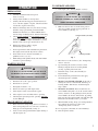
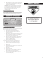
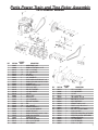
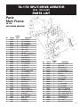
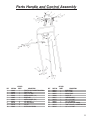
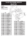
OPERATOR’S MANUAL
AERATOR MODELS:
CA-18
Compact Aerator
TA-17D, TA-25D
Split Drive Aerators
TA-19D, TA-26D
Turf Aerators
48-RT, 60-RT, 72-RT
Tow Aerators
1028 Street Road • P.O. Box 38
Southampton, PA 18966 U.S.A.
TABLE OF CONTENTS
INTRODUCTION . . . . . . . . . . . . . . . . . . . . . . . . . . . . . . . . . . 1
Thank You. . . . . . . . . . . . . . . . . . . . . . . . . . . . . . . . . . . . . 1
Read This Manual . . . . . . . . . . . . . . . . . . . . . . . . . . . . . . 1
Warranty . . . . . . . . . . . . . . . . . . . . . . . . . . . . . . . . . . . . . . 1
Measurements. . . . . . . . . . . . . . . . . . . . . . . . . . . . . . . . . . 1
Serial Numbers . . . . . . . . . . . . . . . . . . . . . . . . . . . . . . . . . 1
Ordering Parts. . . . . . . . . . . . . . . . . . . . . . . . . . . . . . . . . . 1
Directions . . . . . . . . . . . . . . . . . . . . . . . . . . . . . . . . . . . . . 1
TA-26D TURF AERATOR . . . . . . . . . . . . . . . . . . . . . . . . . . 19
Left Side View . . . . . . . . . . . . . . . . . . . . . . . . . . . . . . . . 19
Right Side View . . . . . . . . . . . . . . . . . . . . . . . . . . . . . . . 20
Engine Pulley Components . . . . . . . . . . . . . . . . . . . . . . 21
Water Drum Components . . . . . . . . . . . . . . . . . . . . . . . 21
Drive Components . . . . . . . . . . . . . . . . . . . . . . . . . . . . . 22
OWNERS RECORD . . . . . . . . . . . . . . . . . . . . . . . . . . . . . . . . 1
60-RT TOW AERATOR . . . . . . . . . . . . . . . . . . . . . . . . . . . . 24
Parts Main Frame . . . . . . . . . . . . . . . . . . . . . . . . . . . . . . 24
PRE-DELIVERY CHECK LIST. . . . . . . . . . . . . . . . . . . . . . . 1
DELIVERY CHECK LIST . . . . . . . . . . . . . . . . . . . . . . . . . . . 1
SAFETY PRECAUTIONS . . . . . . . . . . . . . . . . . . . . . . . . . . . 2
Training . . . . . . . . . . . . . . . . . . . . . . . . . . . . . . . . . . . . . . 2
Preparation Safety . . . . . . . . . . . . . . . . . . . . . . . . . . . . . . 2
Engine Safety . . . . . . . . . . . . . . . . . . . . . . . . . . . . . . . . . . 2
Operational Safety . . . . . . . . . . . . . . . . . . . . . . . . . . . . . . 2
OPERATION . . . . . . . . . . . . . . . . . . . . . . . . . . . . . . . . . . . . . . 3
Preparation . . . . . . . . . . . . . . . . . . . . . . . . . . . . . . . . . . . . 3
Starting Engine . . . . . . . . . . . . . . . . . . . . . . . . . . . . . . . . . 3
Transporting Aerator . . . . . . . . . . . . . . . . . . . . . . . . . . . . 3
To Operate Aerator . . . . . . . . . . . . . . . . . . . . . . . . . . . . . . 3
GENERAL MAINTENANCE . . . . . . . . . . . . . . . . . . . . . . . . 4
Aerator Maintenance . . . . . . . . . . . . . . . . . . . . . . . . . . . . 4
Engine Maintenance . . . . . . . . . . . . . . . . . . . . . . . . . . . . . 5
AERATOR STORAGE . . . . . . . . . . . . . . . . . . . . . . . . . . . . . . 5
Storing Aerator . . . . . . . . . . . . . . . . . . . . . . . . . . . . . . . . . 5
Operation After Extended Storage . . . . . . . . . . . . . . . . . . 5
SAFETY DECALS . . . . . . . . . . . . . . . . . . . . . . . . . . . . . . . . . 5
CA-18 COMPACT AERATOR . . . . . . . . . . . . . . . . . . . . . . . . 6
Parts Main Frame . . . . . . . . . . . . . . . . . . . . . . . . . . . . . . 6
Parts Power Train and Tine Rotor Assembly . . . . . . . . . . 7
Parts Handle and Control . . . . . . . . . . . . . . . . . . . . . . . . . 8
TA-17D SPLIT-DRIVE AERATOR . . . . . . . . . . . . . . . . . . . . 9
Parts Main Frame . . . . . . . . . . . . . . . . . . . . . . . . . . . . . . 9
Parts Power Train Assembly. . . . . . . . . . . . . . . . . . . . . . 10
Parts Handle and Control Assembly . . . . . . . . . . . . . . . 11
TA-25D SPLIT-DRIVE AERATOR . . . . . . . . . . . . . . . . . . . 12
Parts Main Frame . . . . . . . . . . . . . . . . . . . . . . . . . . . . . 12
Parts Power Train Assembly. . . . . . . . . . . . . . . . . . . . . . 13
Parts Handle and Control Assembly . . . . . . . . . . . . . . . 14
TA-19D TURF AERATOR . . . . . . . . . . . . . . . . . . . . . . . . . . 15
Left Side View . . . . . . . . . . . . . . . . . . . . . . . . . . . . . . . . 15
Right Side View . . . . . . . . . . . . . . . . . . . . . . . . . . . . . . . 16
Engine Pulley Components . . . . . . . . . . . . . . . . . . . . . . 17
Water Drum Components . . . . . . . . . . . . . . . . . . . . . . . 17
Drive Components . . . . . . . . . . . . . . . . . . . . . . . . . . . . . 18
48-RT TOW AERATOR . . . . . . . . . . . . . . . . . . . . . . . . . . . . 23
Parts Main Frame . . . . . . . . . . . . . . . . . . . . . . . . . . . . . . 23
72-RT TOW AERATOR . . . . . . . . . . . . . . . . . . . . . . . . . . . . 25
Parts Main Frame . . . . . . . . . . . . . . . . . . . . . . . . . . . . . . 25
TWO YEAR LIMITED WARRANTY . . . . . . . . . . . . . . . . . 26
INTRODUCTION
THANK YOU
Thank you for purchasing a CLASSEN Aerator
READ THIS MANUAL
PRE-DELIVERY CHECK LIST
Check the following before you deliver the Aerator to the
customer.
1.
Guards and shields fastened in place.
2.
Decals fastened and legible.
Read this manual carefully in its entirety. It contains safety,
operating, maintenance, and adjustment instructions for your
Aerator. By following the operating and maintenance
instructions you will prolong the life of your equipment and
maintain its maximum efficiency. Failure to do so could result
in personal injury or equipment damage.
3.
Weight bar installed.
4.
Gas lever on engine turned on.
5.
All lubrication points greased.
6.
6:1 gearbox oil level.
7.
Engine oil level.
This manual should be considered a permanent part of your
Aerator and should remain with it if you sell it.
8.
Air cleaner.
9.
Touch up scratches.
WARRANTY
10. Chain(s) tight.
Refer to last page.
11. Lowering handle working properly.
MEASUREMENTS
12. Control handle(s) working to tighten V-belt(s).
U.S. Units of measure are used in this manual.
13. Add fuel, start engine, test run.
SERIAL NUMBERS
Write frame and engine serial numbers, plus model numbers in
“Owner's Record” section below. You may need these numbers
when you order parts. The serial number stick plate is located
on the right rear of the Aerator frame.
ORDERING PARTS
When ordering parts, always give the serial number and model
of your Aerator as well as the quantity, part number and
description of the part needed.
DIRECTIONS
“Right Hand” and “Left Hand” sides of the Aerator are
determined by facing the "back" of the Aerator as you would
operate the machine.
DATE SET UP __________/__________/__________
DELIVERY CHECK LIST
Review the operators manual with the customer.
1.
Classen Mfg., Inc. warranty.
2.
Safe operation and service.
3.
How to use controls.
4.
Operating the machine correctly.
5.
Transporting the Aerator.
6.
Correct fuel and lubricants.
7.
Daily and periodic inspections.
8.
Changing oil after break-in period.
9.
Servicing the Aerator regularly and correctly.
10. Classen Mfg., Inc. parts and service.
11. Give the customer the operators manual and
encourage customer to read it.
DATE DELIVERED __________/__________/__________
OWNER’S RECORD
SIGNATURE _______________________________________
DATE PURCHASED _________________________________
AERATOR MODEL NUMBER _________________________
AERATOR SERIAL NUMBER _________________________
ENGINE MODEL NUMBER __________________________
ENGINE SERIAL NUMBER___________________________
1
SAFETY PRECAUTIONS
1.
Carefully read and follow all caution decals.
(See Pg. 5.)
2.
Operate only in daylight or good artificial light.
3.
Read the instructions carefully. Be familiar with the
controls and the proper use of the equipment.
Do not operate machine unless all guards, shields and
covers are in place and in proper working condition.
4.
Never allow children, teenagers or people unfamiliar
with these instructions to use this piece of equipment.
It is essential all operator safety mechanisms be
connected and in operating condition prior to use.
5.
Avoid operating unit while people, especially children
or pets, are nearby. Keep in mind that the operator or
user is responsible for accidents or hazards occurring
to other people or their property.
Do not change the engine governor settings or overspeed the engine. Operating an engine at excessive
speed may increase the hazard of personal injury.
6.
Disengage the drive control(s) and tine lowering
handle before starting. (See Pg. 3, Fig 1.)
7.
Start the engine carefully with feet well away from
the tines.
8.
Do not put hands, feet or clothing near rotating parts
while the unit is being operated.
9.
Travel up and down slopes at a 45 degree angle rather
than across, to prevent unit from tipping over.
TRAINING
1.
2.
3.
4.
5.
Regard the unit as a piece of power equipment and
teach this regard to all who operate this unit.
Be sure you know how to stop the Aerator at a
moments notice.
PREPARATION SAFETY
1.
The use of personal protective equipment, such as (but
not limited to) protection for the eyes, ears, feet and
head is recommended.
2.
While operating, always wear substantial foot wear
and long trousers. Do not operate the equipment when
barefoot or wearing open sandals.
3.
Area should be free of all obstacles and debris.
ENGINE SAFETY
1.
Handle gasoline with care; it is highly flammable.
2.
Use an approved gasoline container.
3.
Always add fuel before starting the engine.
4.
Fill the fuel tank outdoors.
5.
If fuel is spilled, do not attempt to start the engine.
Move away from the area of the spill and avoid
creating any source of ignition until fuel vapors have
dissipated.
WARNING
DO NOT FILL TANK COMPLETELY FULL.
DO NOT SMOKE WHILE YOU FILL FUEL TANK.
DO NOT REMOVE GAS CAP IF ENGINE
IS RUNNING.
DO NOT OPERATE ENGINE IN A
CONFINED SPACE WHERE DANGEROUS
CARBON MONOXIDE FUMES CAN COLLECT.
2
OPERATIONAL SAFETY
10. Exercise extreme caution when changing direction on
slopes. Do not get too close to sharp drop-offs or
operate unit on excessively steep slopes. DO NOT
release control handle(s) on a slope, this will cause
free wheeling, allowing unit to roll back down the
slope. Make sure to leave yourself room to correct the
problem if one arises.
11. Use caution when pulling the unit towards you.
12. Always stop the tines if unit has to be tilted for
transportation or when crossing surfaces (i.e.
sidewalks, driveways, stepping stones, etc.).
13. Never pick up or carry an Aerator while the engine
is running.
14. Stop the engine and disconnect the spark plug wire:
a) before checking, cleaning or working on unit, and
b) after striking a foreign object (inspect the unit for
damage and make repairs before restarting and
operating).
15. Stop the engine: a) whenever you leave the unit,
b) before refueling, and c) before clearing blockages.
16. Reduce the throttle setting during engine run-out and,
if the engine is provided with shut-off valve, turn the
fuel off at the conclusion of operating.
OPERATION
TO OPERATE AERATOR
1.
Start engine. (See “Starting Engine” section.)
PREPARATION
1.
Carefully read this manual and operate
Aerator correctly.
2.
Always check machine on level ground.
3.
Visually check all moving parts and all fasteners, if
loose or broken, tighten or replace. Check for broken
or bent tines, replace if necessary.
4.
Lubricate all fittings after every four hours of using
machine, using a pressurized gun with standard
lithium base lubricant (see “General Maintenance”
section). Wipe off fittings before and after lubricating.
5.
Check engine crankcase and gear reduction case oil
levels with engine resting in a level position. Add oil
if necessary. (Refer to engine manufacturer’s owners
manual for the correct type and amount of oil.)
6.
Fill the fuel tank according to engine
manufacturer specifications.
7.
For best performance and maximum tine penetration,
thoroughly water lawn the day before aeration.
8.
Police lawn area for obstacles and debris (i.e.
sprinklers, hoses, toys, etc.)
9.
Mark underground sprinkler heads and other hidden
obstacles to prevent damage.
WARNING
CAUTION: TO AVOID INJURY, DO NOT PLACE
FEET OR OTHER BODY PARTS UNDER TINES
WHILE STARTING THE ENGINE.
2.
Make sure the rear tires are in the down position
(tines not touching ground). Slowly pull back on
control handle(s). (See Fig. 1.)
Control Handle (Left Side)
Lowering Handle
Fig. 1
3.
Move Aerator to the work area. (See “Transporting
Aerator” section.)
4.
Upon reaching the work area, release control
handle(s) and push down on lowering handle
(see Fig. 1) putting tines in the turf.
CAUTION: TO AVOID INJURY, DO NOT PLACE
YOUR FEET OR OTHER BODY PARTS UNDER
THE TINES WHILE STARTING THE ENGINE.
5.
Pull back slowly on the control handle(s) to
begin aerating.
6.
For maximum tine penetration into turf, apply
downward pressure on handle.
1.
Turn fuel cock to the “open” position.
7.
2.
Turn choke on (closed).
3.
Turn ignition switch to “on”.
Models CA-18, TA-19D & TA-26D: At the end of
aerating run, release control handle and lift up on
lowering handle. Turn Aerator around and repeat
steps 5 and 6.
4.
Pull recoil starter rope until engine starts.
8.
5.
After engine is warm, turn off choke (open).
6.
Allow engine to run one minute before operating.
7.
Check engine rpm setting before operating. DO NOT
exceed 3600 rpm.
Models TA-17 & TA-25: These models have two
control handles designed so it can be steered around
corners, obstacles, etc. By pulling back only the left
control handle, the Aerator will turn left, by pulling
back only the right control handle, unit will turn right.
Pull both control handles back to go straight.
9.
When finished aerating, lift up on lowering handle to
move wheels into transport position. (See
“Transporting Aerator” section.)
STARTING ENGINE
WARNING
TRANSPORTING AERATOR
1.
Raise tines before transporting unit across surfaces or
before transporting from one work area to another by
lifting up on lowering handle (see Fig. 1).
2.
Aerator can be transported with the engine running or
with the engine off.
10. To stop engine, take hands off control handle(s).
11. Turn off ignition switch.
3
GENERAL MAINTENANCE
AERATOR MAINTENANCE
TO KEEP THE AERATOR IN GOOD
OPERATING CONDITION, PERFORM
THE FOLLOWING:
•
When replacement parts are required, use genuine
Classen parts or parts with equivalent characteristics
including type, strength, and material. Failure to do so
may result in product malfunction and possible injury
to the operator and/or bystanders.
•
Any warning decal that becomes illegible should be
replaced immediately. (See Pg. 5.)
•
Do not operate equipment without shield(s) in place.
Do not make any adjustments or perform any
maintenance while the engine is running.
•
•
•
Check roller chain(s) for tightness. Follow these steps:
Model CA-18 (See Fig.3.)
1.
Disconnect spark plug.
2.
Take off pulley guard by removing two nuts and
lock washers.
3.
Loosen nut (B) by turning counter-clockwise until nut
comes in contact with head of bolt (A).
4.
Tighten bolt (A) until chain is tight between front axle
sprocket (D) and tine assembly sprocket (E).
(See Note Opposite Page)
5.
Retighten nut (B) by turning clockwise against
lock washer (C).
6.
Replace pulley guard, nuts and lock washers and
retighten nuts.
A
B
C
Thoroughly clean all tines inside and out when
aerating is completed and apply a light coat of oil to
prevent rust on tines.
D
E
Always lubricate Aerator each time it is put into
service. Wipe off lubrication fittings before and after
each lubrication. The number of lubrication fittings
vary depending on model of Aerator.
Model CA-18 - Qty 2, one in each rear wheel assembly.
Models TA-19D/TA-26D (water drum models) - Qty 3, one in
each rear wheel assembly and one on the idler/clutch arm pivot
bearing. (See Fig. 2.)
Fig. 3
Main Frame Top Flat (Left Side)
Models TA-19/TA-26 (front tire models) - Qty. 5, one in each
wheel assembly and one on the idler/clutch arm pivot bearing.
(See Fig. 2.)
Models TA-17D/TA-25D - Qty. 4, one in each wheel assembly
and one in each idler/clutch arm pivot bearing. (See Fig. 2.)
Pulley Guard
Idler Clutch Arm
(Right Side)
Main Frame (Left Side)
Fig. 4
Model TA-17/TA-19/TA-25/TA-26 (See Fig. 4.)
Fig. 2
•
Keep drive belt(s) free of oil and dirt.
1.
Disconnect spark plug.
2.
Take off pulley guard (see Fig. 2) by removing bolts,
etc. which attach it to the frame.
3.
Loosen the bolts, nuts, lock washers, and flat washers
(Key 4) to allow movement of the pillow block
bearings only (Key 5). Loosen nuts only, do
not remove.
4.
Loosen and unthread the two 5/16'' nuts (Key 2) down
to top of chain tightening bracket (Key 3).
5.
Turn the tap bolts (Key 1) evenly clockwise so jack
shaft stays level with frame until chain(s) is/are tight.
Models TA-17D/TA-25D - If belts slip due to normal belt
stretch, engine can be adjusted forward within slotted holes to
tighten belts.
•
4
Check roller chain(s) for wear. Apply a light coat of
No. 30 oil or penetrating chain lubricant to keep the
chain(s) clean and in proper running order.
6.
When adjustment is complete, retighten the bolts (Key
4) on the pillow block bearings (Key 5) and replace
the pulley guard and fasteners.
SAFETY DECALS
NOTE: Excessive roller chain tightness will shorten the
life of the bearings. Chain(s) should have movement of
0.18 in./4mm free play back and forth at center point
between front drive sprocket and rear tine
assembly sprocket.
ENGINE MAINTENANCE
(Refer to engine manufacturer's owners manual) Check engine
and gear reduction case oil level with engine resting in a level
position. Inspect air filter element and replace if necessary.
AERATOR STORAGE
WARNING
SAFETY WARNING: TO PREVENT POSSIBLE
EXPLOSION OR IGNITION OF VAPORIZED FUEL,
DO NOT STORE EQUIPMENT WITH FUEL IN
TANK OR CARBURETOR OR NEAR OPEN FLAME
(I.E. FURNACE, WATER HEATER, PILOT LIGHT).
All Guards Must Be In
Place While Machine
Is In Operation
STORAGE INSTRUCTIONS
Before the Aerator is put into storage for any period exceeding
30 days, the following steps should be taken.
1.
Drain all fuel from fuel tank and fuel lines.
2.
Start engine and run until all fuel is used from
carburetor float bowl.
3.
While engine is still warm, drain the crankcase oil and
replace with the proper weight oil corresponding to
the season the Aerator will next be used.
4.
Remove the spark plug and squirt a small quantity of
engine oil into the cylinder. Turn the engine over a
few times to distribute that oil.
5.
Lubricate all lubrication fittings.
To put Aerator into operation after an extended storage:
1.
Check for loose parts and tighten if necessary.
2.
Check for cracked or broken tines and replace.
3.
Fill fuel tank.
4.
Check engine and gear reduction case oil levels (with
engine in a level position).
5.
Start engine.
6.
Check for fuel leaks.
7.
Check operation of control handle(s) to make sure
unit stops when lever is released forward.
8.
Aerator is equipped with fuel shut-off valve, close
valve before transporting.
5
CA-18 COMPACT AERATOR
(S.N. 1062 & UP)
PARTS LIST
Parts Main Frame
CA-18 COMPACT AERATOR
KEY
1
2
3
4
5
6
7
8
9
10
11
12
13
14
15
16
17
18
19
20
21
22
23
6
PART NO.
400127
400138
400131
500129
500130
500043
400126
300080
300081
500133
500115
500101
600027
100031
500053
500016
400142
500071
500137
500164
500029
500136
100250
QTY/PER
SHEET
1
1
1
8
6
4
2
2
2
2
2
2
1
2
4
2
1
2
6
4
4
4
2
DESCRIPTION
MAIN FRAME
PULLEY GUARD
HANDLE MOUNT
3/8" NUT
3/8" LOCK WASHER
3/8" x 1" BOLT
WEIGHT BAR
1/2" WHEEL PIVOT PIN
WEIGHT STOP
5/16" x 1" BOLT
5/16" LOCK WASHER
5/16" NUT
KEYED SHAFT
REAR TIRE, 8"
5/8" FLAT WASHER
5/32" x 1-1/4" COTTER PIN
ARM, L.H. REAR AXLE SUPPORT
1/4" x 5/8" FINE BOLT
1/4" LOCK WASHER
1/4" FENDER WASHER
1/4" x 3/4" BOLT
1/4" NUT
SPRING
KEY
24
25
26
27
28
29
30
31
32
33
34
35
36
37
38
39
40
41
42
43
44
45
PART NO.
400141
500169
500149
500106
500006
500011
100270
500042
500179
300107
100256
500218
500139
500154
100055
100069
100073
100074
100096
300079
500083
500078
QTY/PER
SHEET
1
2
2
4
2
2
1
4
1
2
2
1
1
1
1
1
1
2
1
2
2
2
DESCRIPTION
ARM, R.H. REAR AXLE SUPPORT
5/16" LOCK NUT
1/2" x 2" BOLT
1/2" NUT
1/2" LOCK WASHER
3/16" SQUARE KEY
PULLEY, CLUTCH CABLE SUPPORT
3/8" FLAT WASHER
V-BELT GUIDE BOLT (3/8" x 2-3/4")
PULLEY MOUNTING BRACKET
DECAL, "CA-18"
1/4" x 1-1/4" BOLT
1/4" LOCK NUT
3/8" x 2-3/4" BOLT
DECAL, "SERIAL NUMBER" (NOT SHOWN)
DECAL, "DANGER" (NOT SHOWN)
LUBRICATION TAG (NOT SHOWN)
DECAL, "CLASSEN" (NOT SHOWN)
DECAL, "ALL GUARDS" (NOT SHOWN)
WHEEL PIVOT FLAT
5/16" FLAT WASHER
"E" RING
Parts Power Train and Tine Rotor Assembly
CA-18 COMPACT AERATOR
KEY
1
1
2
3
4
5
6
7
8
9
10
11
12
13
14
15
16
17
18
19
20
21
22
23
24
25
26
27
28
29
PART NO.
100037
100094
500147
500115
500101
100255
500011
100245
100247
200034
100252
500159
400136
500130
500129
500091
100010
500042
700023
100032
500169
100253
500003
300073
100248
100254
100025
400137
500114
100043
QTY/PER
SHEET
1
1
52
18
18
1
3
1
4
1
1
1
1
1
1
1
1
3
1
24
50
1
1
1
2
1
1
1
1
1
DESCRIPTION
HONDA ENGINE 4.0 HP
BRIGGS & STRATTON I.C. 3.5 HP
5/16" x 1-1/2" BOLT
5/16" LOCK WASHER
5/16" NUT
BX 38 V-BELT
3/16" SQUARE KEY
PULLEY & HUB w/o KEY, AB x 3/4" x 9"
BEARING,PLATED FLANGE w/ COLLAR,3/4" 2 BOLT
JACKSHAFT, 3/4"
SPROCKET, #40 B12 x 3/4"
3/8" x 2-3/4" BOLT
ARM, BELT TIGHTENER
3/8" LOCK WASHER
3/8" NUT
3/8" x 2" BOLT
IDLER PULLEY
3/8" FLAT WASHER
TINE SHAFT ASSEMBLY
TINE
5/16" LOCK NUT
SPROCKET, #40 B27 x 1"
1/4" x 7/8" HALF MOON KEY
SPACER, TINE SHAFT
BEARING,PLATED FLANGE w/ COLLAR,1" 2 BOLT
CHAIN, #40 x 109 PITCH
CONNECTING LINK
ARM, CHAIN TIGHTENER
5/16" x 2-1/4" TAP BOLT
IDLER SPROCKET
KEY
30
31
32
33
34
35
36
37
38
39
40
41
42
43
44
45
46
47
PART NO.
500174
500006
500106
500175
100246
500172
600026
100249
100038
500041
500173
500140
100263
100264
100265
500034
500083
500073
QTY/PER
SHEET
1
1
1
1
2
2
1
1
1
2
1
12
1
1
2
1
2
1
DESCRIPTION
1/2" x 1-3/4" BOLT
1/2" LOCK WASHER
1/2" NUT
3/8" x 3-3/4" BOLT
TIRE & WHEEL, 10 x 3W
ROLL PIN, 1/4" x 1-1/2"
AXLE, FRONT DRIVE
SPROCKET, #40 B21 x 3/4"
PULLEY w/ 3/4" HUB, 3/4" x 3"
3/8" LOCK NUT
KEY, 3/16" x 7/8" HALF MOON
5/16" x 3/4" BOLT
DEFLECTOR, HONDA ENG. (NOT SHOWN)
DEFLECTOR, B&S ENG. (NOT SHOWN)
SCREWS, DEFLECTOR
1/2" FLAT WASHER
5/16" FLAT WASHER
5/16" x 1-1/4" BOLT
7
Parts Handle and Control
CA-18 COMPACT AERATOR
KEY
1
2
3
4
5
6
7
8
9
10
8
PART NO.
400128
400017
400180
100007
500134
500130
500129
500041
500178
100251
QTY/PER
SHEET
1
1
1
2
9
1
1
27
2
2
DESCRIPTION
MAIN HANDLE
LOWERING HANDLE
CONTROL HANDLE
RUBBER GRIP
3/8" x 1-1/4" BOLT
3/8" LOCK WASHER
3/8" NUT
3/8" LOCK NUT
3/8" x 3-1/4" BOLT
HANDLE LOCK RING
KEY
11
12
13
14
15
16
17
18
19
20
PART NO.
400130
500091
400133
200035
100034
400129
400132
500042
500083
500204
QTY/PER
SHEET
1
4
1
1
1
1
1
4
4
2
DESCRIPTION
ARM, L.H. LINKAGE
3/8" x 2" BOLT
LH LINKAGE PIVOT
CLUTCH CABLE
SPRING
ARM, R.H. LINKAGE
RH LINKAGE PIVOT
3/8" FLAT WASHER
5/16" FLAT WASHER
3/8" x 2-1/4" CARRIAGE BOLT
TA-17D SPLIT-DRIVE AERATOR
(S.N. 100 & UP)
PARTS LIST
Parts
Main Frame
TA-17D
SPLIT-DRIVE AERATOR
KEY
1
2
3
4
5
6
7
8
9
10
11
12
13
14
15
16
17
18
19
20
21
22
23
24
25
26
27
28
29
30
31
32
33
34
35
36
37
38
39
PART NO.
100069
500083
500140
500115
100419
400093
100153
500133
500101
500163
500169
400071
400089
500134
400086
500042
500041
500029
500136
500001
500137
500011
100021
400021
500129
500130
100010
500091
400087
400020
500170
500114
300049
300007
400080
100074
400056
400015
100040
QTY/PER
SHEET
1
8
3
8
2
1
2
1
5
4
4
1
1
2
1
12
2
4
4
2
4
4
4
1
7
4
2
2
1
1
3
4
4
2
1
3
1
2
2
DESCRIPTION
DECAL, "DANGER"
5/16" FLAT WASHER
5/16" x 3/4" BOLT
5/16" LOCK WASHER
RUBBER EDGING
PULLEY GUARD
DECAL, "TA-17"
5/16" x 1" BOLT
5/16" NUT
5/16" x 3/4" CARRIAGE BOLT
5/16" LOCK NUT
CHAIN GUARD, (L.H.)
CHAIN GUARD, (R.H.)
3/8" x 1-1/4" BOLT
CLUTCH ARM, (R.H.)
3/8" FLAT WASHER
3/8" LOCK NUT
1/4" x 3/4" BOLT
1/4" NUT
1/4" x 28 GREASE FITTING
1/4" LOCK WASHER
3/16" x 1" SQ. KEY
BRASS BUSHING
IDLER ARM, (R.H.)
3/8" NUT
3/8" LOCK WASHER
IDLER PULLEY
3/8" x 2" BOLT
IDLER ARM, (L.H.)
CLUTCH ARM, (L.H.)
3/8" x 3-1/2" BOLT
5/16" x 2-1/4" TAP BOLT
CHAIN TIGHTENING PLATE
LINKAGE ARM
TA-17D MAIN FRAME
DECAL, "CLASSEN"
WEIGHT BAR
SPRING ARM
FRAME SPRING
KEY
40
41
42
43
44
45
46
47
48
49
50
51
52
53
54
55
56
57
58
59
60
61
62
63
PART NO.
100031
200007
300009
500194
500164
400013
300006
500131
500135
300005
500149
500106
500006
500174
500053
500016
100096
100157
100055
100257
100073
500034
500043
400014
QTY/PER
SHEET
2
1
1
6
2
1
2
12
2
2
2
4
2
2
2
2
1
2
1
1
1
6
1
1
DESCRIPTION
8" REAR TIRE ASSEMBLY
KEYED SHAFT
WEIGHT STOP FLAT
3/4" FLAT WASHER
1/4" FENDER WASHER
REAR AXLE SUPPORT ARM, (L.H.)
PIVOT FLAT
1/2" LOCK NUT
1/2" x 2-1/2" BOLT
BUSHING SPACER
1/2" x 2" BOLT
1/2" NUT
1/2" LOCK WASHER
1/2" x 1-3/4" BOLT
5/8" FLAT WASHER
5/32" x 1-1/4" COTTER PIN
DECAL, "ALL GUARDS" (N.S.)
DECAL, "SPLIT-DRIVE" (N.S.)
DECAL, "SERIAL NUMBER" (N.S.)
DECAL, "PATENT" (N.S.)
LUBRICATION TAG (N.S.)
1/2" FLAT WASHER
3/8" x 1" BOLT
REAR AXLE SUPPORT ARM, (R.H.)
9
Parts Power Train Assembly
TA-17D SPLIT-DRIVE AERATOR
KEY
1
2
3
4
5
6
7
8
9
10
11
12
13
14
15
16
17
18
19
20
21
22
23
10
PART NO.
100037
500147
500083
500115
500101
100420
500231
100013
200024
500173
500074
100245
100150
200023
100004
500150
500034
500131
300132
200009
300011
300131
500003
QTY/PER
SHEET
1
60
20
15
21
2
1
4
1
2
8
2
2
1
4
8
15
8
2
2
2
2
2
DESCRIPTION
4.0 HP HONDA ENGINE
5/16" x 1-1/2" BOLT
5/16" FLAT WASHER
5/16" LOCK WASHER
5/16" NUT
3" x 3/4" PULLEY w/ HUB
3/16" x 1-3/4" SQ. KEY
3/4" BEARING w/ COLLAR
JACK SHAFT ASSEMBLY, (R.H.)
3/16" x 7/8" HALF MOON KEY
5/16" x 1-3/4" BOLT
9" PULLEY & HUB w/o KEY
BX-45 V-BELT
JACK SHAFT ASSEMBLY, (L.H.)
1" BEARING w/ COLLAR
1/2" x 1-1/2" BOLT
1/2" FLAT WASHER
1/2" LOCK NUT
1" OUTSIDE SPACER
#40 x 36 SPROCKET & HUB
OUTSIDE DRUM SHAFT SPACER
2" MACHINERY WASHER
1/4" x 7/8" HALF MOON KEY
KEY
24
25
26
27
28
29
30
31
32
33
34
35
36
37
38
39
40
41
42
43
44
45
PART NO.
700018
500169
100032
500106
500006
200015
100043
500174
100151
100155
500043
300057
500130
500129
100108
100083
100109
100085
700009
100087
100084
700011
QTY/PER
SHEET
2
60
24
3
3
1
3
2
1
2
3
1
3
3
1
1
1
1
1
1
1
2
DESCRIPTION
TINE DISC SHAFT ASSEMBLY
5/16" LOCK NUT
PLUGGING TINE
1/2" NUT
1/2" LOCK WASHER
#40 x 30 SPROCKET
IDLER SPROCKET
1/2" x 1-3/4" BOLT
#40 x 75 PITCH CHAIN w/ LINK
1" 3-BOLT FLANGE BEARING w/ COLLAR
3/8" x 1" BOLT
3/16" LOWER PLATE
3/8" LOCK WASHER
3/8" NUT
#40 x 139 PITCH CHAIN
SMALL STEEL WASHER
WATER DRUM PLUG
WATER DRUM
DRUM AXLE
SMALL RUBBER GASKET
LARGE RUBBER GASKET
INNER HALF-PLATE w/ STUDS
Parts Handle and Control Assembly
TA-17D SPLIT-DRIVE AERATOR
KEY
1
2
3
4
5
6
7
8
9
10
PART NO.
100035
400088
500134
400082
100007
400091
500041
500130
500129
100034
QTY/PER
SHEET
1
1
2
1
2
1
9
6
6
2
DESCRIPTION
THROTTLE CABLE CONNECTING SPRING
THROTTLE ARM
3/8" x 1-1/4" BOLT
CONTROL HANDLE, (L.H.)
RUBBER GRIP
CONTROL HANDLE, (R.H.)
3/8" LOCK NUT
3/8" LOCK WASHER
3/8" NUT
CLUTCH CABLE SPRING
KEY
11
12
13
14
15
16
17
18
19
20
PART NO.
400018
500043
300054
100020
400017
500170
500042
200020
100149
500162
QTY/PER
SHEET
1
6
1
2
1
2
4
2
1
1
DESCRIPTION
MAIN HANDLE
3/8" x 1" BOLT
HANDLE BRACE
PLASTIC TIE
LOWERING HANDLE
3/8" x 3-1/2" BOLT
3/8" FLAT WASHER
CLUTCH CABLE (NOT SHOWN)
THROTTLE CABLE w/ CONNECTING ENDS
3/8" x 6-1/2" BOLT
11
TA-25D SPLIT-DRIVE AERATOR
(S.N. 100 & UP)
PARTS LIST
Parts
Main Frame
TA-25D
SPLIT-DRIVE AERATOR
KEY
1
2
3
4
5
6
7
8
9
10
11
12
13
14
15
16
17
18
19
20
21
22
23
24
25
26
27
28
29
30
31
32
33
34
35
36
37
38
39
12
PART NO.
100069
500083
500115
500140
100419
400092
100152
500133
500101
500163
500169
400071
400089
500134
400085
500042
500041
500029
500136
500001
500137
500011
100021
400021
500129
500130
100010
500091
400087
400083
500170
500114
300049
300007
400079
100074
400057
400015
100040
QTY/PER
SHEET
1
8
8
3
2
1
2
1
5
4
4
1
1
2
1
12
2
4
4
2
4
4
4
1
7
4
2
2
1
1
2
4
4
2
1
3
1
2
2
DESCRIPTION
DECAL, "DANGER"
5/16" FLAT WASHER
5/16" LOCK WASHER
5/16" x 3/4" BOLT
RUBBER EDGING
PULLEY GUARD
DECAL, "TA-25"
5/16" x 1" BOLT
5/16" NUT
5/16" x 3/4" CARRIAGE BOLT
5/16" LOCK NUT
CHAIN GUARD, (L.H.)
CHAIN GUARD, (R.H.)
3/8" x 1-1/4" BOLT
CLUTCH ARM, (R.H.)
3/8" FLAT WASHER
3/8" LOCK NUT
1/4" x 3/4" BOLT
1/4" NUT
1/4" x 28 GREASE FITTING
1/4" LOCK WASHER
3/16" x 1" SQ. KEY
BRASS BUSHING
IDLER ARM, (R.H.)
3/8" NUT
3/8" LOCK WASHER
IDLER PULLEY
3/8" x 2" BOLT
IDLER ARM, (L.H.)
CLUTCH ARM, (L.H.)
3/8" x 3-1/2" BOLT
5/16" x 2-1/4" TAP BOLT
CHAIN TIGHTENING PLATE
LINKAGE ARM
TA-25D MAIN FRAME
DECAL, "CLASSEN"
WEIGHT BAR
SPRING ARM
FRAME SPRING
KEY
40
41
42
43
44
45
46
47
48
49
50
51
52
53
54
55
56
57
58
59
60
61
62
63
64
PART NO.
100031
200012
300009
500194
500164
400026
300006
500131
500135
300005
500149
500106
500006
500174
300002
500034
100096
100157
100055
100257
100073
500043
500096
400025
500165
QTY/PER
SHEET
2
1
1
6
2
1
2
12
2
2
2
4
2
2
2
8
1
2
1
1
1
1
2
1
1
DESCRIPTION
8" REAR TIRE ASSEMBLY
KEYED SHAFT
WEIGHT STOP FLAT
3/4" FLAT WASHER
1/4" FENDER WASHER
REAR AXLE SUPPORT ARM, (R.H.)
PIVOT FLAT
1/2" LOCK NUT
1/2" x 2-1/2" BOLT
BUSHING SPACER
1/2" x 2" BOLT
1/2" NUT
1/2" LOCK WASHER
1/2" x 1-3/4" BOLT
AXLE PIN
1/2" FLAT WASHER
DECAL, "ALL GUARDS" (N.S.)
DECAL, "SPLIT-DRIVE" (N.S.)
DECAL, "SERIAL NUMBER" (N.S.)
DECAL, "PATENT" (N.S.)
LUBRICATION TAG (N.S.)
3/8" x 1" BOLT
5/32" x 3" BRIDGE PIN CLIP
REAR AXLE SUPPORT ARM, (L.H.)
3/8" x 4-1/2" BOLT
Parts Power Train Assembly
TA-25D SPLIT-DRIVE AERATOR
KEY
1
2
3
4
5
6
7
8
9
10
11
12
13
14
15
16
17
18
19
20
21
22
PART NO.
100150
100013
200022
500101
500115
500083
500173
500074
100245
200021
100037
500147
100420
500231
100004
500150
500034
500131
300011
200009
300131
500003
QTY/PER
SHEET
2
4
1
21
15
20
2
8
2
1
1
79
2
1
4
8
15
8
2
2
2
2
DESCRIPTION
BX-45 V-BELT
3/4" BEARING w/ COLLAR
JACK SHAFT ASSEMBLY, (R.H.)
5/16" NUT
5/16" LOCK WASHER
5/16" FLAT WASHER
3/16" x 7/8" HALF MOON KEY
5/16" x 1-3/4" BOLT
9" PULLEY & HUB w/o KEY
JACK SHAFT ASSEMBLY, (L.H.)
4.0 HP HONDA ENGINE
5/16" x 1-1/2" BOLT
3" x 3/4" PULLEY w/ HUB
3/16" x 1-3/4" SQ. KEY
1" BEARING w/ COLLAR
1/2" x 1-1/2" BOLT
1/2" FLAT WASHER
1/2" LOCK NUT
OUTSIDE DRUM SHAFT SPACER
#40 x 36 SPROCKET & HUB
2" MACHINERY WASHER
1/4" x 7/8" HALF MOON KEY
KEY
23
24
25
26
27
28
29
30
31
32
33
34
35
36
37
38
39
40
41
42
43
PART NO.
700017
100032
500169
500106
500006
100043
500174
100151
100155
300057
500130
500129
100108
100109
100083
100087
100086
700010
100084
700011
200015
QTY/PER
SHEET
2
36
84
3
3
3
2
1
2
1
3
3
1
1
1
1
1
1
1
2
1
DESCRIPTION
TINE DISC SHAFT ASSEMBLY
PLUGGING TINE
5/16" LOCK NUT
1/2" NUT
1/2" LOCK WASHER
IDLER PULLEY
1/2" x 1-3/4" BOLT
#40 x 75 PITCH CHAIN w/ LINK
1" 3-BOLT FLANGE BEARING w/ COLLAR
3/16" LOWER PLATE
3/8" LOCK WASHER
3/8" NUT
#40 x 139 PITCH CHAIN
WATER DRUM PLUG
SMALL STEEL WASHER
SMALL RUBBER GASKET
WATER DRUM
DRUM AXLE
LARGE RUBBER GASKET
INNER HALF-PLATE w/ STUDS
#40 x 30 SPROCKET
13
Parts Handle and Control Assembly
TA-25D SPLIT-DRIVE AERATOR
KEY
1
2
3
4
5
6
7
8
9
10
14
PART NO.
100035
400088
500134
400081
100007
400090
500041
500130
500129
100034
QTY/PER
SHEET
1
1
2
1
2
1
9
6
6
2
DESCRIPTION
THROTTLE CABLE CONNECTING SPRING
THROTTLE ARM
3/8" x 1-1/4" BOLT
CONTROL HANDLE (L.H.)
RUBBER GRIP
CONTROL HANDLE (R.H.)
3/8" LOCK NUT
3/8" LOCK WASHER
3/8" NUT
CLUTCH CABLE SPRING
KEY
11
12
13
14
15
16
17
18
19
20
PART NO.
400028
500043
300054
100020
400027
500170
500042
200020
100149
500162
QTY/PER
SHEET
1
6
1
2
1
2
4
2
1
1
DESCRIPTION
MAIN HANDLE
3/8" x 1" BOLT
HANDLE BRACE
PLASTIC TIE
LOWERING HANDLE
3/8" x 3-1/2" BOLT
3/8" FLAT WASHER
CLUTCH CABLE, (NOT SHOWN)
THROTTLE CABLE w/ CONNECTING ENDS
3/8" x 6-1/2" BOLT
TA-19D TURF AERATOR
(S.N. 000540 & UP)
PARTS LIST
Left Side View
(Shown without Pulley Guard)
TA-19D TURF AERATOR
KEY
1
2
3
4
5
6
7
8
9
10
11
12
13
14
15
16
17
18
19
20
21
22
23
24
25
QTY/PER
PART NO. SHEET
400072 1
100085 1
500015 3
500011 6
200007 1
500054 2
500109 2
500044 2
400013 1
100031 2
500053 2
500131 4
300006 2
500060 6
500046 2
100040 2
400015 2
500047 2
300005 2
400021 1
500001 1
500107 1
100039 1
400020 1
100010 1
DESCRIPTION
FRAME, MAIN
DRUM, WATER
1/4" X 3/4" BOLT W/ LOCK WASHER & NUT
KEY, 3/16" X 1" SQUARE
SHAFT, KEYED
WASHER, (3) 3/4" FLAT
1/4"-28 X 5/8" BOLT W/ FENDER WASHER & LOCK WASHER
1/2" X 1-3/4" BOLT W/ LOCK WASHER & (2) NUTS
ARM, L.H. REAR AXLE SUPPORT
TIRE ASSEMBLY, 8" REAR
WASHER, 5/8" FLAT
NUT, 1/2" LOCK
FLAT, PIVOT
3/8" X 1" BOLT W/ FLAT WASHER, LOCK WASHER & NUT
1/2" X 2" BOLT W/ (3) FLAT WASHERS & (2) LOCK NUTS
SPRING, FRAME
ARM, SPRING
1/2" X 2-1/2" BOLT W/ (2) LOCK NUTS
SPACER, BUSHING
ARM, IDLER
GREASE FITTING, 1/4" X 28
3/8" X 1" BOLT W/ (2) FLAT WASHERS & LOCK NUT
V-BELT, BX43
ARM, CLUTCH
PULLEY, IDLER
KEY
26
27
28
29
30
31
32 _
33
34
35
36
37
38
39
40
41
42
43
44
45
46
47
48
49
50
51
52
53
54
55
56
57
58
59
60
61
62
63
QTY/PER
PART NO. SHEET
500008 1
500099 2
500098 3
300037 1
500005 4
300009 1
300071 1
500051 6
100037 1
400115 1
500114 2
500083 2
500115 2
500101 2
300049 2
100013 2
500010 4
100041 1
200006 1
100108 1
500124 2
400071 1
100032 30
300007 2
500049 2
400017 1
500048 2
100036 1
100020 2
200008 1
400018 1
500050 2
100035 1
400019 1
100033 2
500055 1
100034 1
500016 2
DESCRIPTION
3/8" X 2" BOLT W/ LOCK WASHER & NUT
3/8" X 1-1/4" BOLT W/ FLAT WASHER, LOCK WASHER & NUT
3/8" X 3-1/2" BOLT W/ (2) FLAT WASHERS, LOCK WASHER & (2) NUTS
PLATE, ADJUSTER
5/16" X 1-1/2" BOLT W/ LOCK WASHER & NUT (NOT SHOWN)
WEIGHT STOP
PLATE, HANDLE BRACE GUSSET
3/8" X 1 " BOLT W/ LOCK NUT
ENGINE W/ EXHAUST DEFLECTOR, 4HP HONDA
BRACE, HANDLE
5/16" X 2-1/4" TAP BOLT
WASHER, 5/16" FLAT
WASHER, 5/16" LOCK
NUT, 5/16"
PLATE, CHAIN TIGHTENING
BEARING W/ COLLAR, 3/4" PILLOW BLOCK
5/16" X 1-3/4" BOLT W/ (2) FLAT WASHERS, LOCK WASHER & NUT
9" PULLEY W/ 3/4" HUB & 3/16" SQ. KEY
JACK SHAFT W/ #40 X 13 SPROCKET & HUB
CHAIN, #40 X 139 PITCH
5/16" X 3/4" CARRIAGE BOLT W/ LOCK NUT
GUARD, CHAIN
TINE, PLUGGING
ARM, LINKAGE
3/8" X 1-1/4" BOLT W/ FLAT WASHER & (2) LOCK NUTS
HANDLE, LOWERING
3/8" X 3-1/2" BOLT W/ (2) LOCK NUTS
CABLE W/ CONNECTING ENDS, THROTTLE
TIE, PLASTIC
CABLE, CLUTCH
HANDLE, MAIN
3/8" X 1-1/4" BOLT W/ (2) LOCK NUTS
SPRING, THROTTLE CABLE CONNECTING
HANDLE, CONTROL
GRIP, 1/8" X 1"
3/8" X 1-1/4" BOLT W/ LOCK WASHER, LOCK NUT & NUT
SPRING, CLUTCH CABLE
COTTER PIN, 5/32" X 1-1/4"
15
Right Side View
TA-19D TURF AERATOR
KEY
1
2
3
4
5
6
7
8
9
10
11
12
13
14
15
16
17
18
19
20
21
22
23
24
25
26
27
28
29
30
16
QTY/PER
PART NO. SHEET
400072 1
100085 1
500015 3
500011 6
200007 1
500054 2
500109 2
500044 2
400014 1
100031 2
500053 2
500131 4
300006 2
500060 6
500046 2
100040 2
400015 2
500047 2
300005 2
100021 2
400021 1
400020 1
500107 1
500042 1
500051 6
100032 30
400071 1
300007 2
400017 1
500049 2
DESCRIPTION
FRAME, MAIN
DRUM, WATER
1/4" X 3/4" BOLT W/ LOCK WASHER & NUT
KEY, 3/16" X 1" SQUARE
SHAFT, KEYED
WASHER, (3) 3/4" FLAT
1/4"-28 X 5/8" BOLT W/ FENDER WASHER & LOCK WASHER
1/2" X 1-3/4" BOLT W/ LOCK WASHER & 2 NUTS
ARM, R.H. REAR AXLE SUPPORT
TIRE ASSEMBLY, 8" REAR
WASHER, 5/8" FLAT
NUT, 1/2" LOCK
FLAT, PIVOT
3/8" X 1" BOLT W/ FLAT WASHER, LOCK WASHER & NUT
1/2" X 2" BOLT W/ (3) FLAT WASHERS & (2) LOCK NUTS
SPRING, FRAME
ARM, SPRING
1/2" X 2-1/2" BOLT W/ (2) LOCK NUTS
SPACER, BUSHING
BUSHING, BRASS
ARM, IDLER
ARM, CLUTCH
3/8" X 1" BOLT W/ 2 FLAT WASHERS & LOCK NUT
WASHER, 3/8" FLAT
3/8" X 1" BOLT W/ LOCK NUT
TINE, PLUGGING
GUARD, CHAIN
ARM, LINKAGE
HANDLE, LOWERING
3/8" X 1-1/4" BOLT W/ FLAT WASHER & (2) LOCK NUTS
KEY
31
32
33
34
35
36
37
38
39
40
41
42
QTY/PER
PART NO. SHEET
500048 2
100036 1
100020 2
400018 1
500050 2
100035 1
400019 1
100033 2
100034 1
200008 1
400115 1
400022 1
43
44
45
46
47
48
49
50
100027
100037
300071
500005
500056
400056
300009
500016
1
1
1
4
4
1
1
2
DESCRIPTION
3/8" X 3-1/2" BOLT W/ (2) LOCK NUTS
CABLE W/ CONNECTING ENDS, THROTTLE
TIE, PLASTIC
HANDLE, MAIN
3/8" X 1-1/4" BOLT W/ (2) LOCK NUTS
SPRING, THROTTLE CABLE CONNECTING
HANDLE, CONTROL
GRIP, 1/8" X 1"
SPRING, CLUTCH CABLE
CABLE, CLUTCH
BRACE, HANDLE
PULLEY GUARD W/ (3) 5/16" X 3/4" BOLTS,
(3) FLAT WASHERS, (3) LOCK WASHERS & NUT
SPRING, THROTTLE
ENGINE W/ EXHAUST DEFLECTOR, 4HP HONDA
PLATE, HANDLE BRACE GUSSET
5/16" X 1-1/2" BOLT W/ LOCK WASHER & NUT
5/16" X 3/4" BOLT W/ FLAT WASHER, LOCK WASHER & NUT
WEIGHT BAR
WEIGHT STOP
COTTER PIN, 5/32" X 1-1/4"
Top View Looking Down on the Front of the Aerator
Engine Pulley
Components
TA-19D TURF AERATOR
KEY
1
2
3
4
5
6
7
8
9
10
PART NO.
500011
500098
100081
500060
500099
300037
400072
100038
200014
100037
QTY/PER
SHEET
6
3
1
6
2
1
1
1
1
1
DESCRIPTION
KEY, 3/16" x 1" SQUARE
3/8" x 3-1/2" BOLT w/ (2) FLATS, LOCK, & (2) NUTS
BEARING, 3/4" 2-BOLT
3/8" x 1" BOLT w/ FLAT, LOCK, & NUT
3/8" x 1-1/4" BOLT w/ FLAT, LOCK, & NUT
PLATE, ADJUSTER
FRAME, MAIN
PULLEY, 3/4" x 3"
COUPLER w/ STUB SHAFT, 3/4"
ENGINE, 4.0 HP HONDA
Front View of Water Drum & Mounting
Water Drum
Components
TA-19D TURF AERATOR
KEY
1
2
3
4
5
6
7
8
9
10
11
12
13
PART NO.
700009
100004
500040
100083
700011
100084
200015
500100
500101
100085
100087
100108
100109
QTY/PER
SHEET
1
4
8
1
2
1
1
12
6
1
1
1
1
DESCRIPTION
AXLE, DRUM
BEARING w/ ECCENTRIC COLLAR, 1" PILLOW BLOCK
1/2" x 1-3/4" BOLT w/ FLAT WASHER & LOCK NUT
WASHER, SMALL STEEL
INNER HALF PLATE w/ STUDS
GASKET, LARGE RUBBER
SPROCKET, #40 x 30
LOCK NUT, 5/16" TWO-WAY
NUT, 5/16" STANDARD
DRUM, WATER
GASKET, SMALL RUBBER
CHAIN, #40 x 139 PITCH (NOT SHOWN)
PLUG, WATER DRUM (NOT SHOWN)
17
Drive Components
TA-19D TURF AERATOR
KEY
1
2
3
4
5
6
7
8
9
10
11
12
13
14
15
16
17
18
18
PART NO.
100043
500037
500038
500034
100108
100025
100032
500128
500040
200009
100004
700020
200015
700009
100085
300011
500003
200006
QTY/PER
SHEET
2
1
1
2
1
1
30
60
8
1
4
1
1
1
1
1
1
1
DESCRIPTION
IDLER SPROCKET, #40 x 17 x 1/2"
1/2" x 1-3/4" BOLT w/ LOCK & NUT
LOCK & NUT, 1/2"
FLAT WASHERS, (2) 1/2"
CHAIN, #40 x 139 PITCH
CONNECTING LINK, #40
TINE, PLUGGING
5/16" x 1-1/2" BOLT w/ LOCK NUT
1/2" x 1-3/4" BOLT w/ FLAT & LOCK NUT
SPROCKET w/ 1" HUB, #40 x 36
BEARING w/ ECCENTRIC COLLAR, 1" PILLOW BLOCK
SHAFT ASSEMBLY, TINE DISC
SPROCKET, #40 x 30
AXLE, DRUM
DRUM, WATER
SPACER, 1" OUTSIDE DRUM SHAFT
KEY, 1/4" x 7/8" HALF MOON
JACK SHAFT ASSEMBLY, #40 x 13
TA-26D TURF AERATOR
(S.N. 000252 & UP)
PARTS LIST
Left Side View
(Shown without Pulley Guard)
TA-26D TURF AERATOR
KEY
1
2
3
4
5
6
7
8
9
10
11
12
13
14
15
16
17
18
19
20
21
22
23
24
25
QTY/PER
PART NO. SHEET
400073 1
100086 1
500015 3
500011 6
200012 1
500054 2
500109 2
500044 2
400025 1
100031 2
100049 2
500131 4
300006 2
500060 6
500046 2
100040 2
400015 2
500047 2
300055 2
400021 1
500001 1
500107 1
100039 1
400020 1
100010 1
DESCRIPTION
FRAME, MAIN
DRUM, WATER
1/4" X 3/4" BOLT W/ LOCK WASHER & NUT
KEY, 3/16" X 1" SQUARE
SHAFT, KEYED
WASHER, (3) 3/4" FLAT
1/4"-28 X 5/8" BOLT W/ FENDER WASHER & LOCK WASHER
1/2" X 1-3/4" BOLT W/ LOCK WASHER & (2) NUTS
ARM, L.H. REAR AXLE SUPPORT
TIRE ASSEMBLY, 8" REAR
PIN W/ CLIP, REAR AXLE
NUT, 1/2" LOCK
FLAT, PIVOT
3/8" X 1" BOLT W/ FLAT WASHER, LOCK WASHER & NUT
1/2" X 2" BOLT W/ (3) FLAT WASHERS & (2) LOCK NUTS
SPRING, FRAME
ARM, SPRING
1/2" X 2-1/2" BOLT W/ (2) LOCK NUTS
SPACER W/ (2) FLAT WASHERS, & BUSHING
ARM, IDLER
GREASE FITTING, 1/4" X 28
3/8" X 1" BOLT W/ (2) FLAT WASHERS & LOCK NUT
V-BELT, BX43
ARM, CLUTCH
PULLEY, IDLER
KEY
26
27
28
29
30
31
32
33
34
35
36
37
38
39
40
41
42
43
44
45
46
47
48
49
50
51
52
53
54
55
56
57
58
59
60
61
62
QTY/PER
PART NO. SHEET
500008 1
500099 2
500098 3
300037 1
500005 4
300009 1
300071 1
500051 6
100037 1
400115 1
500114 2
500083 2
500115 2
500101 2
300049 2
100013 2
500010 4
100041 1
200011 1
100108 1
500124 2
400071 1
100032 42
300007 2
500049 2
400027 1
500048 2
100036 1
100020 2
200008 1
400028 1
500050 2
100035 1
400053 1
100033 2
500055 1
100034 1
DESCRIPTION
3/8" X 2" BOLT W/ LOCK WASHER & NUT
3/8" X 1-1/4" BOLT W/ FLAT WASHER, LOCK WASHER & NUT
3/8" X 3-1/2" BOLT W/ (2) FLAT WASHERS,LOCK WASHER & (2) NUTS
PLATE, ADJUSTER
5/16" X 1-1/2" BOLT W/ LOCK WASHER & NUT (NOT SHOWN)
WEIGHT STOP
PLATE, HANDLE BRACE GUSSET
3/8" X 1" BOLT W/ LOCK NUT
ENGINE W/ EXHAUST DEFLECTOR, 4HP HONDA
BRACE, HANDLE
5/16" X 2-1/4" TAP BOLT
WASHER, 5/16" FLAT
WASHER, 5/16" LOCK
NUT, 5/16"
PLATE, CHAIN TIGHTENING
BEARING W/ COLLAR, 3/4" PILLOW BLOCK
5/16" X 1-3/4" BOLT W/ (2) FLAT WASHERS, LOCK WASHER & NUT
9" PULLEY W/ 3/4" HUB & 3/16" SQ. KEY
JACK SHAFT W/ #40 X 13 SPROCKET & HUB
CHAIN, #40 X 139 PITCH
5/16" X 3/4" CARRIAGE BOLT W/ LOCK NUT
GUARD, CHAIN
TINE, PLUGGING
ARM, LINKAGE
3/8" X 1-1/4" BOLT W/ FLAT WASHER & (2) LOCK NUTS
HANDLE, LOWERING
3/8" X 3-1/2" BOLT W/ (2) LOCK NUTS
CABLE W/ CONNECTING ENDS, THROTTLE
TIE, PLASTIC
CABLE, CLUTCH
HANDLE, MAIN
3/8" X 1-1/4" BOLT W/ (2) LOCK NUTS
SPRING, THROTTLE CABLE CONNECTING
HANDLE, CONTROL
GRIP 1/8" X 1"
3/8" X 1-1/4" BOLT W/ LOCK WASHER, LOCK NUT & NUT
SPRING, CLUTCH CABLE
19
Right Side View
TA-26D TURF AERATOR
KEY
1
2
3
4
5
6
7
8
9
10
11
12
13
14
15
16
17
18
19
20
21
22
23
24
25
26
27
28
29
30
20
QTY/PER
PART NO. SHEET
400073 1
100086 1
500015 3
500011 6
200012 1
500054 2
500109 2
500044 2
400026 1
100031 2
100049 2
500131 4
300006 2
500060 6
500046 2
100040 2
400015 2
500047 2
300055 2
100021 2
400021 1
400020 1
500107 1
500042 1
500051 6
100032 42
400071 1
300007 2
400027 1
500049 2
DESCRIPTION
FRAME, MAIN
DRUM, WATER
1/4" X 3/4" BOLT W/ LOCK WASHER & NUT
KEY, 3/16" X 1" SQUARE
SHAFT, KEYED
WASHER, (3) 3/4" FLAT
1/4"-28 X 5/8" BOLT W/ FENDER WASHER & LOCK WASHER
1/2" X 1-3/4" BOLT W/ LOCK WASHER & 2 NUTS
ARM, R.H. REAR AXLE SUPPORT
TIRE ASSEMBLY, 8" REAR
PIN W/ CLIP, REAR AXLE
NUT, 1/2" LOCK
FLAT, PIVOT
3/8" X 1" BOLT W/ FLAT WASHER, LOCK WASHER & NUT
1/2" X 2" BOLT W/ (3) FLAT WASHERS & (2) LOCK NUTS
SPRING, FRAME
ARM, SPRING
1/2" X 2-1/2" BOLT W/ (2) LOCK NUTS
SPACER W/ (2) FLAT WASHERS & BUSHING
BUSHING, BRASS
ARM, IDLER
ARM, CLUTCH
3/8" X 1" BOLT W/ 2 FLAT WASHERS & LOCK NUT
WASHER, 3/8" FLAT
3/8" X 1 BOLT W/ LOCK NUT
TINE, PLUGGING
GUARD, CHAIN
ARM, LINKAGE
HANDLE, LOWERING
3/8" X 1-1/4" BOLT W/ FLAT WASHER & (2) LOCK NUTS
KEY
31
32
33
34
35
36
37
38
39
40
41
42
QTY/PER
PART NO. SHEET
500048 2
100036 1
100020 2
400028 1
500050 2
100035 1
400053 1
100033 2
100034 1
200008 1
400115 1
400029 1
43
44
45
46
47
48
49
100027
100037
300071
500005
500056
400057
300009
1
1
1
4
4
1
1
DESCRIPTION
3/8" X 3-1/2" BOLT W/ (2) LOCK NUTS
CABLE W/ CONNECTING ENDS, THROTTLE
TIE, PLASTIC
HANDLE, MAIN
3/8" X 1-1/4" BOLT W/ (2) LOCK NUTS
SPRING, THROTTLE CABLE CONNECTING
HANDLE, CONTROL
GRIP, 1/8" X 1"
SPRING, CLUTCH CABLE
CABLE, CLUTCH
BRACE, HANDLE
PULLEY GUARD W/ (3) 5/16" X 3/4" BOLTS,
(3) FLAT WASHERS, (3) LOCK WASHERS & NUT
SPRING, THROTTLE
ENGINE W/ EXHAUST DEFLECTOR, 4HP HONDA
PLATE, HANDLE BRACE GUSSET
5/16" X 1-1/2" BOLT W/ LOCK WASHER & NUT
5/16" X 3/4" BOLT W/ FLAT WASHER, LOCK WASHER & NUT
WEIGHT BAR
WEIGHT STOP
Top View Looking Down on the Front of the Aerator
Engine Pulley
Components
TA-26D TURF AERATOR
KEY
1
2
3
4
5
6
7
8
9
10
PART NO.
500011
500098
100081
500060
500099
300037
400073
100038
200013
100037
QTY/PER
SHEET
6
3
1
6
2
1
1
1
1
1
DESCRIPTION
KEY, 3/16" x 1" SQUARE
3/8" x 3-1/2" BOLT w/ (2) FLATS, LOCK, & (2) NUTS
BEARING, 3/4" 2-BOLT
3/8" x 1" BOLT w/ FLAT, LOCK, & NUT
3/8" x 1-1/4" BOLT w/ FLAT, LOCK, & NUT
PLATE, ADJUSTER
FRAME, MAIN
PULLEY, 3/4" x 3"
COUPLER w/ STUB SHAFT, 3/4"
ENGINE, 4.0 HP HONDA
Front View of Water Drum & Mounting
Water Drum
Components
TA-26D TURF AERATOR
KEY
1
2
3
4
5
6
7
8
9
10
11
12
13
PART NO.
700010
100004
500040
100083
700011
100084
200015
500100
500101
100086
100087
100108
100109
QTY/PER
SHEET
1
4
8
1
2
1
1
12
6
1
1
1
1
DESCRIPTION
AXLE, DRUM
BEARING w/ ECCENTRIC COLLAR, 1" PILLOW BLOCK
1/2" x 1-3/4" BOLT w/ FLAT WASHER & LOCK NUT
WASHER, SMALL STEEL
INNER HALF PLATE w/ STUDS
GASKET, LARGE RUBBER
SPROCKET, #40 x 30
LOCK NUT, 5/16" TWO-WAY
NUT, 5/16" STANDARD
DRUM, WATER
GASKET, SMALL RUBBER
CHAIN, #40 x 139 PITCH (NOT SHOWN)
PLUG, WATER DRUM (NOT SHOWN)
21
Drive Components
TA-26D TURF AERATOR
KEY
1
2
3
4
5
6
7
8
9
10
11
12
13
14
15
16
17
18
22
PART NO.
100043
500037
500038
500034
100108
100025
100032
500128
500040
200009
100004
700019
200015
700010
100086
300011
500003
200011
QTY/PER
SHEET
2
1
1
2
1
1
42
84
8
1
4
1
1
1
1
1
1
1
DESCRIPTION
IDLER SPROCKET, #40 x 17 x 1/2"
1/2" x 1-3/4" BOLT w/ LOCK & NUT
LOCK & NUT, 1/2"
FLAT WASHERS, (2) 1/2"
CHAIN, #40 x 139 PITCH
CONNECTING LINK, #40
TINE, PLUGGING
5/16" x 1-1/2" BOLT w/ LOCK NUT
1/2" x 1-3/4" BOLT w/ FLAT & LOCK NUT
SPROCKET w/ 1" HUB, #40 x 36
BEARING w/ ECCENTRIC COLLAR, 1" PILLOW BLOCK
SHAFT ASSEMBLY, TINE DISC
SPROCKET, #40 x 30
AXLE, DRUM
DRUM, WATER
SPACER, 1" OUTSIDE DRUM SHAFT
KEY, 1/4" x 7/8" HALF MOON
JACK SHAFT ASSEMBLY, #40 x 13
48-RT TOW AERATOR
(S.N. 000337 & UP)
PARTS LIST
Parts Main Frame
48-RT TOW AERATOR
KEY
1
2
3
4
5
6
7
8
9
10
11
12
13
14
15
16
17
18
PART NO.
400060
100099
100069
400153
400062
400063
100100
400064
100103
100074
500182
300044
500129
500130
100101
500042
500159
100032
QTY/PER
SHEET
1
1
1
1
1
2
2
2
2
3
2
1
8
8
4
8
8
48
DESCRIPTION
LIFT ROD
3/4" x 4-1/2" HITCH PIN w/CLIP
DECAL, "DANGER"
MAIN FRAME
R.H SIDE PLATE
LATCH PIN
SPRING
WHEEL FORK
TIRE & WHEEL ASSEMBLY
DECAL, "CLASSEN"
3/16" X 1-1/2" COTTER PIN
WHEEL FORK AXLE
3/8" NUT
3/8" LOCK WASHER
1" PILLOW BLOCK BEARING
3/8" FLAT WASHER
3/8" x 3" BOLT
TINE
KEY
19
20
21
22
23
24
25
26
27
28
29
30
31
32
33
34
35
36
PART NO.
700026
300106
300058
500211
500169
100055
400065
500016
500053
300045
100104
500311
400058
500213
500214
500195
400059
500215
QTY/PER
SHEET
2
2
2
48
48
1
1
4
4
2
2
1
1
2
2
2
1
1
DESCRIPTION
TINE SHAFT
TINE END SPACER
CENTER BEARING SPACER
5/16" x 1-3/4" GR. 8 BOLT
5/16" LOCK NUT
DECAL, "SERIAL NUMBER" (not shown)
L.H. SIDE PLATE
5/32" x 1-1/4" COTTER PIN
5/8" FLAT WASHER
WHEEL AXLE
7/8" LIFT ARM PIN w/ LOCK WASHERS & NUTS
1/2" LOCK NUT
HITCH
3/4" X 4" BOLT
3/4" NUT
3/4" LOCK WASHER
HITCH GUSSET
1/2" x 3" BOLT
23
60-RT TOW AERATOR
(S.N. 000161 & UP)
PARTS LIST
Parts Main Frame
60-RT TOW AERATOR
KEY
1
2
3
4
5
6
7
8
9
10
11
12
13
14
15
16
17
18
24
PART NO.
400060
100099
100069
400157
400062
400063
100100
400064
100103
100074
500182
300051
500129
500130
100101
500042
500159
100032
QTY/PER
SHEET
1
1
1
1
1
2
2
2
2
3
2
1
8
8
4
8
8
60
DESCRIPTION
LIFT ROD
3/4" x 4-1/2" HITCH PIN
DECAL, "DANGER"
MAIN FRAME
R.H SIDE PLATE
LATCH PIN
SPRING
WHEEL FORK
TIRE & WHEEL ASSEMBLY
DECAL, "CLASSEN"
3/16" X 1-1/2" COTTER PIN
WHEEL FORK AXLE
3/8" NUT
3/8" LOCK WASHER
1" PILLOW BLOCK BEARING
3/8" FLAT WASHER
3/8" x 3" BOLT
TINE
KEY
19
20
21
22
23
24
25
26
27
28
29
30
31
32
33
34
35
36
PART NO.
700027
300106
300058
500211
500169
100055
400065
500016
500053
300045
100104
500311
400058
500213
500214
500195
400059
500215
QTY/PER
SHEET
2
2
2
48
48
1
1
4
4
2
2
1
1
2
2
2
1
1
DESCRIPTION
TINE SHAFT
TINE END SPACER
CENTER BEARING SPACER
5/16" x 1-3/4" GR. 8 BOLT
5/16" LOCK NUT
DECAL, "SERIAL NUMBER" (not shown)
L.H. SIDE PLATE
5/32" x 1-1/4" COTTER PIN
5/8" FLAT WASHER
WHEEL AXLE
7/8" LIFT ARM PIN w/ LOCK WASHERS & NUTS
1/2" LOCK NUT
HITCH
3/4" X 4" BOLT
3/4" NUT
3/4" LOCK WASHER
HITCH GUSSET
1/2" x 3" BOLT
72-RT TOW AERATOR
(S.N. 144 & UP)
PARTS LIST
Parts Main Frame
72-RT TOW AERATOR
KEY
1
2
3
4
5
6
7
8
9
10
11
12
13
14
15
16
17
18
PART NO.
400060
100099
100069
400159
400062
400063
100100
400064
100103
100074
500182
300052
500129
500130
100101
500042
500159
100032
QTY/PER
SHEET
1
1
1
1
1
2
2
2
2
3
2
1
8
8
4
8
8
72
DESCRIPTION
LIFT ROD
3/4" x 4-1/2" HITCH PIN
DECAL, "DANGER"
MAIN FRAME
R.H SIDE PLATE
LATCH PIN
SPRING
WHEEL FORK
TIRE & WHEEL ASSEMBLY
DECAL, "CLASSEN"
3/16" X 1-1/2" COTTER PIN
WHEEL FORK AXLE
3/8" NUT
3/8" LOCK WASHER
1" PILLOW BLOCK BEARING
3/8" FLAT WASHER
3/8" x 3" BOLT
TINE
KEY
19
20
21
22
23
24
25
26
27
28
29
30
31
32
33
34
35
36
PART NO.
700029
300106
300058
500211
500169
100055
400065
500016
500053
300045
100104
500311
400058
500213
500214
500195
400059
500215
QTY/PER
SHEET
2
2
2
48
48
1
1
4
4
2
2
1
1
2
2
2
1
1
DESCRIPTION
TINE SHAFT
TINE END SPACER
CENTER BEARING SPACER
5/16" x 1-3/4" GR. 8 BOLT
5/16" LOCK NUT
DECAL, "SERIAL NUMBER" (not shown)
L.H. SIDE PLATE
5/32" x 1-1/4" COTTER PIN
5/8" FLAT WASHER
WHEEL AXLE
7/8" LIFT ARM PIN w/ LOCK WASHER & NUTS
1/2" LOCK NUT
HITCH
3/4" X 4" BOLT
3/4" NUT
3/4" LOCK WASHER
HITCH GUSSET
1/2" x 3" BOLT
25
1028 Street Road • P.O. Box 38
Southampton, PA 18966 U.S.A.
TWO YEAR LIMITED WARRANTY
Effective April 1, 2007
For the period of two years from the date of purchase, CLASSEN MFG., INC. will repair or replace for the
original purchaser free of charge, any part or parts found upon the examination of our factory authorized
service station, or by the factory in Norfolk, Nebraska, to be defective in material or workmanship. All
transportation charges on parts submitted for repair or replacement under this warranty shall be borne by
the purchaser.
This warranty does not include engines or engine parts, tires, batteries, or gearboxes that are covered
under separate warranties furnished by their manufacturer or supplier, nor does it include normal
maintenance parts, including but not limited to, spark plugs, points, filters, blades, and lubricants.
All service under this warranty will be furnished or performed by our factory authorized service stations.
There is no other expressed warranty. Implied warranties, including those of merchantability and fitness
for a particular purpose, are limited to two years from the date of purchase and to the extent permitted by
law, any and all implied warranties are excluded. The above remedy of repair and replacement of defective
parts is the purchaser’s exclusive remedy for any defect, malfunction or breach of warranty. Liability for
incidental or consequential damages under any and all warranties is excluded to the extent permitted
by law.
NORMAL RESPONSIBILITIES OF THE SELLER AND THE USER
1.
2.
3.
4.
5.
The Distributor or Dealer is responsible for the proper assembly and preparation of the product for
delivery to the end user.
The User is responsible for reading the Manual and Instructions.
The User is responsible for proper operation and maintenance as described in the manual.
The User is responsible for the replacement of wear items such as blades, belts, tires, batteries, etc.
The User is responsible for damage due to improper operation and maintenance, as well as abuse.
All claims must be received by the factory 30 days after the end of the warranty period to receive warranty
consideration.
26
See the complete line of Turf Care Products
from CLASSEN
COMPACT AERATORS
CA-18H
CA-18B
SPLIT DRIVE AERATORS
TA-25D
TA-17D
TURF AERATORS
TA-19D
TA-26D
TOW/3PT AERATORS
48RT
60RT
72RT
3 PT AERATORS
48R
60R
72R
84R
SOD CUTTERS
SC-12
SC-18
SC-20
TURF RAKES
TR-20H
TR-20B
TRC-20H
TRC-20B
TURF SEEDERS
TS-20H
TS-20B
DRILL SEEDER
DS-20
TRAILERS
AST
SAT
Classen reserves the right to make changes or add improvements to its products at any time without incurring any obligation to make
such changes to products manufactured previously. Classen, or its distributors and dealers, accept no responsibility for variations
which may be evident in the actual specifications of its products and the statements and descriptions contained in this publication.
1028 Street Road • P.O. Box 38
Southampton, PA 18966 U.S.A.