1
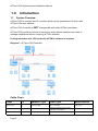
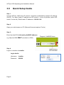
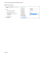
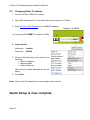
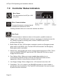
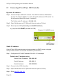
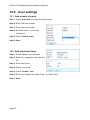
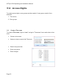
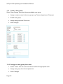
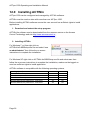
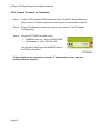
ACTpro 1500
Single Door IP Controller
Operating & Installation Instructions
18-00079
Issue 1
This manual refers to the ACTpro 1500 a TCP/IP based control unit supporting
up to 32 doors.
Access Control Technology Ltd. reserve the right to change the contents of this
manual and the system it applies to without prior notice.
While every effort has been taken by ACT to ensure the accuracy of the
information contained within this document, ACT assumes no responsibility for
any errors or omissions. No liability is assumed for damages resulting from the
use of information contained within this document.
Access Control Technology
Unit C1, South City Business Centre,
Tallaght,
Dublin 24,
Ireland.
Tel: +353-1-4662570
UK LoCall: 0845 300 5204
Fax: +353-1-4662570
Web: www.accesscontrol.ie
E-mail: [email protected]
Copyright © 2012 Access Control Technology Ltd.
ACTpro 1500 Operating and Installation Manual
Introduction ..............................................................................5 1.0 1.1 System Overview ................................................................................. 5 2.0 Installation diagram .................................................................7 3.0 Quick Setup Guide ...................................................................8 4.0 Adding Door Stations ............................................................11 5.0 IP Address Configuration ......................................................12 5.1 Configuring DHCP address ................................................................ 12 5.2 Configuring Static IP address ............................................................. 12 5.3 Changing Static IP address ................................................................ 13 6.1 Readers .............................................................................................. 14 6.2 Push Button (PB)................................................................................ 15 6.3 Door Contact (DC).............................................................................. 15 6.4 Break Glass Monitoring ...................................................................... 15 7.0 Controller Status Indicators ..................................................16 8.0 Controller Configuration .......................................................17 8.1 Connecting PC to ACTpro 1500 Controller ........................................ 18 8.2 Change Installer Password ................................................................ 19 8.3 Change User Password ..................................................................... 19 8.4 Set controller Date and Time .............................................................. 20 9.0 Door settings:.........................................................................21 9.1 Enable and name doors ..................................................................... 21 9.2 Set Door Relay Timers ....................................................................... 21 9.3 Set Door Timed Actions ..................................................................... 21 10.0 Page 3
User settings ........................................................................22 ACTpro 1500 Operating and Installation Manual
10.1 Add a batch of cards .......................................................................... 22 10.2 Add individual Users ........................................................................... 22 11.0 Access Rights ......................................................................23 11.1 Create a Time zone........................................................................ 23 11.2 Create a door group ....................................................................... 24 11.3 Create a User group........................................................................ 25 11.4 Assign a user group to a user............................................................. 25 12.0 Installing ACTWin ................................................................26 13.0 Run ACTWin for the first time. ............................................27 14.0 Create a new Database ........................................................28 15.0 Connect to 1500 Controller .................................................29 16.0 Backup/Restore....................................................................30 17.0 Upgrading Firmware ............................................................31 18.0 Troubleshooting...................................................................32 18.1 Unknown Card.................................................................................... 32 18.2 Access Denied ................................................................................... 32 18.3 Door Offline ........................................................................................ 32 18.4 Cannot Connect to Controller ............................................................. 33 19.0 Product Specification ..........................................................35 Ordering Information: .....................................................................35 Page 4
ACTpro 1500 Operating and Installation Manual
1.0
1.1
Introduction
System Overview
ACTpro 1500 is a single door IP controller which can be expanded to 32 doors with
ACTpro 100e door stations.
ACTpro 1500 Controller is NOT interoperable with other ACTpro controllers.
ACTpro 1500 controller includes a web server which allows installers and users to
manage installations without requiring ACTWin software.
If using more than one 1500 controller ACTWin software is required.
Diagram 1: ACTpro 1500 Controller
Cable Chart
From
To
Network Type
Cable Type*
Max Distance
ACTpro 1500
PC
Ethernet or USB
CAT5 or mini USB
100m or 5m
ACTpro 1500
ACTpro 100
RS485
Shielded and twisted single pair cable Belden 9501 or equivalent.
1.4Km
ACTpro 1500 & 100
Readers
ACT protocol
8 Core Screen
100m
Page 5
ACTpro 1500 Operating and Installation Manual
Diagram 2: illustrates two ACTpro 1500 controllers managing 28 doors (maximum is 32
doors). With more than one ACTpro 1500 controller ACTWin software required.
Diagram 2: Multiple ACTpro 1500 Controllers
Cable Chart
From
To
Network Type
Cable Type*
Max Distance
ACTpro 1500
PC
Ethernet or USB
CAT5 or mini USB
100m or 5m
ACTpro 1500
ACTpro 100
RS485
Shielded and twisted single pair cable Belden 9501 or equivalent.
1.4Km
ACTpro 1500 & 100
Readers
ACT protocol
8 Core Screen
100m
Page 6
ACTpro 1500 Operating and Installation Manual
2.0
2.1
Installation diagram
Diagram 3: ACTpro 1500 typical wiring
Note: For electric strike lock (de-energized
lock) wire between “Common” and “Normally
open” pins.
Page 7
ACTpro 1500 Operating and Installation Manual
3.0
Quick Setup Guide
Step 1:
Connect ACTpro 1500 to the IP network. Controller is defaulted for dynamic IP address
(DHCP). For static (fixed) IP address set DIP switch 1 to the off position (Move DIP
switch 1 to the left). Default static IP address is 192.168.1.60.
Step 2:
Open your web browser on PC (Microsoft Internet explorer, Firefox)
Step 3:
Enter http://act1500-(followed by NetBIOS address).
Diagram4: NetBIOS Name
e.g. http://act1500-59487 (see label on PCB)
Step 4:
Login to controller as installer
Login details:
Username:
installer
Password:
999999
Page 8
ACTpro 1500 Operating and Installation Manual
Step 5:
Enable Doors
•
Select “Door Config” menu which lists all 32 doors.
•
Select door, check enable box and enter a door name.
•
Press Save
Step 6:
Logout from installer menu (top right corner).
Step 7:
Login to controller as user
Login details:
Username:
user
Password:
123456
Page 9
ACTpro 1500 Operating and Installation Manual
Step 8: Add card batch
•
Select “Add card batch” icon from home
screen
•
Enter
1. Enter First card number
2. Enter last card number
3. Set “Start user” to 1 (for a new
installation),
4. Enable users.
•
Press Save
Page 10
ACTpro 1500 Operating and Installation Manual
4.0
Adding Door Stations
The ACTpro 1500 includes door 1. The controller can be expanded to 32 doors using
ACTpro Door Stations.
Diagram 5: Extending ACTpro 1500 controller with ACTpro door stations.
Doors Network 1 - support doors addressed from 2 to 16, Doors Network 2 support
doors addressed from 17 to 32.
The ACTpro door stations on the Doors network must be daisy chained (star
configuration not permitted). Maximum length of Doors network should not exceed
1.4km. On Doors network connect A to A; B to B and 0V to 0V.
DIP switch settings.
Door Station 2-16 addressing
Page 11
Door Station 17 - 32 DIP addressing
ACTpro 1500 Operating and Installation Manual
5.0
5.1
IP Address Configuration
Configuring DHCP address
1. Remove power from ACTpro 1500 controller.
2. Set DHCP switch 1 to the on position (Move switch 1 to the right).
3. Reapply power to the ACTpro 1500 controller.
5.2
Configuring Static IP address
1. Remove power from ACTpro 1500 controller.
2. Set DHCP DIP switch 1 to the off position (Move switch 1 to the left).
3. Reapply power to the ACTpro 1500 controller.
Page 12
ACTpro 1500 Operating and Installation Manual
5.3
Changing Static IP address
1. Connect ACTpro 1500 to IP network
2. Open Web browser on PC (use Microsoft Internet explorer or Firefox)
3. Enter http://act1500-(folowed by the NetBIOS address)
Diagram 6 NetBIOS
e.g. http://act1500-59487 (see label on PCB)
4. Logon details:
Username:
installer
Password:
999999
5. Choose Communication menu and set the
following
• Static IP Address
• Network Mask
• Default Gateway
Note: ask the network administrator for the
above
6. Press Save
Note: use the new IP address when connecting to the controller.
Quick Setup is now complete.
Page 13
ACTpro 1500 Operating and Installation Manual
6.0
6.1
Hardware Installation Guide
Readers
Diagram 7: Wiring of entry & exit readers.
Reader
terminal block
Recommended
wiring colour
Signal information
SENSE
White
For Entry readers connect the reader SENSE cable or
terminal to the SENSE input pin.
For Exit readers, do not use this input.
CLOCK
Green
This is the clock or strobe signal input on the ACTpro
1500.
Connect the reader CLOCK cable or terminal on the
reader to CLOCK input pin.
DATA
Blue
This is the Data input.
Connect the reader DATA cable or terminal on the
reader to DATA input pin
+12V
Red
Positive +12V DC Supply voltage for the reader
0V
Black
0V Supply Voltage for the reader.
RED
Brown
Red LED control output from the ACTpro 1500.
Connect the reader RED cable or terminal on the reader
to RED output pin on the controller
GREEN
Yellow
Green LED control output from the ACTpro 1500.
Connect the reader GREEN cable or terminal on the
reader to GREEN output pin on the ACTpro controller
Page 14
ACTpro 1500 Operating and Installation Manual
6.2
Push Button (PB)
Push button is connected between PB input and 0 Volts. When push
button is pressed the main relay is be activated for the configured time.
Diagram 8
Push button is also referred to as Exit Button, Egress Button, Request
To Exit.
Diagram 8
6.3
Door Contact (DC)
Connect door contact between DC input and 0Volts. Diagram 9
Diagram 9
6.4
Break Glass Monitoring
Connect Normally closed output from the break glass to B/GL input on the controller.
Diagram 10
Diagram 10
Enable break glass reporting
Login to the Controller as Installer.
Select “Door Config” menu option
Select door for which break glass
monitoring is required.
Under “Operation” tab select Breakglass
Save.
Page 15
ACTpro 1500 Operating and Installation Manual
7.0
Controller Status Indicators
Blue: Power
This indicates that the ACTpro 1500
has power.
Blue: Communications
Constant illumination indicates that all
enabled door stations are online.
Flashing indicates that one or more door stations are offline.
Red: Fault.
This illuminates to indicate an alarm on the system, possible causes are:
1. Tamper open: ACTpro1500 plastic housing is not closed. In situations where the
ACT plastic housing is not being used, connect TAMPER input on the
ACTpro1500 PCB to 0V.
2. Break Glass: ACTpro 1500 provides a method to monitor an Emergency break
glass switch via the B/GL input. The fault LED will illuminate if the Emergency
break glass switch is activated.
3. Mains Fault: ACTpro1500 will accept a mains present signal from a PSU. This is
wired into MAINS PRESENT input on the PCB. When the PSU has no mains
supply the fault is active.
4. Door Station offline: When one or more enabled door stations is not
communicating with the ACTpro 1500 the Fault LED illuminates and the
appropriate network communications indicator will flash.
5. Low Supply Voltage: When voltage to the +12V terminal is less than +9V.
6. Fuse Blown: The +12V output on the READER terminals is current limited to
provide short circuit protection. The Fault LED will illuminate if too much current
is pulled from this connection.
Page 16
ACTpro 1500 Operating and Installation Manual
8.0
Controller Configuration
ACTpro 1500 has two built-in user accounts, installer & user.
Installer account: is used to configure global communication and door settings.
Installer login details:
Username Password
installer
999999
User account: is used for day to day management of the system, such as manage
users and access rights.
User login details:
Username Password
user
Page 17
123456
ACTpro 1500 Operating and Installation Manual
8.1
Connecting PC to ACTpro 1500 Controller
Dynamic IP address:
Step1: Connect ACTpro 1500 to IP network. The 1500 Controller is defaulted for
dynamic IP address (DHCP). For static (fixed) IP address set DIP switch 1 to
the off position (Move DIP switch 1 to the left).
The Default static IP address is 192.168.1.60.
Step2: Open Web browser on PC (Microsoft Internet explorer, Firefox)
Step3: Enter http://act1500-(folowed by the NetBIOS address)
e.g. http://act1500-59487 (see label on PCB)
Diagram 11: NetBIOS name
Static IP address:
If the ACTpro 1500 controller does not have access to a DHCP server, configure
ACTpro 1500 controller to use static IP address (see section 5).
Step 1: Configure the PC with IP address 192.168.1.61 for example
Default static IP address setting
Default Static IP address: 192.168.1.60
Default Gateway:
192.168.1.1
Default Netmask:
255.255.255.0
Step 2: Connect to the 1500 Controller.
Step 3: Open Web browser on PC (Microsoft Internet explorer, Firefox)
Step 4: Enter http://192.168.1.61
Page 18
ACTpro 1500 Operating and Installation Manual
8.2
Change Installer Password
Login to the controller as installer
Login details:
Username:
installer
Password:
999999
Change installer password
Step 1: Login in as “installer”
Step 2: Go to the “settings” link (top–right of screen)
Step 3: Select “PIN code” tab
Step 4: Enter new 6 digit code
Step 5: Save
8.3
Change User Password
Login to the controller as user
Login details:
Username:
user
Password:
123456
Change user password
Step 1: Login as “user”
Step 2: Go to the “settings” link (top–right of screen)
Step 3: Select “PIN code” tab
Step 4: Enter new 6 digit code
Step 5: Save
Warning: It’s important that the passwords for “installer” and “user” are different
and retained in a safe location as the passwords cannot be retrieved. If either
code is lost a factory default will be required.
Page 19
ACTpro 1500 Operating and Installation Manual
8.4
Set controller Date and Time
Step 1: Login under the user account
Step 2: Select setting option (top-right of screen)
Step 3: Select “Date and Time” tab.
Step 4: Enter correct date and time
Step 5: Set Date or Set Time
Page 20
ACTpro 1500 Operating and Installation Manual
9.0
9.1
Door settings:
Enable and name doors
Step 1: login as installer
Step 2: Select “Door Config” menu option
Step 3: Select desired door
Step 4: Enable and name door
Step 6: Save
9.2
Set Door Relay Timers
Step 1: login in as installer
Step 2: Select “Door Config” menu option
Step 3: Select desired door
Step 4: Select “Timers” tab
Step 5: Enter new time.
Step 6: Save
9.3
Set Door Timed Actions
Step 1: login in as installer
Step 2: Select “Door Config” menu option
Step 3: Select desired door
Step 4: Select “Actions” tab
Step 5: Select timezone against the action.
Step 6: Save
Page 21
ACTpro 1500 Operating and Installation Manual
10.0 User settings
10.1 Add a batch of cards
Step 1: Select “Add card” icon from the home screen
Step 2: Enter First card number
Step 3: Enter Last card number
Step 4: Set Start user to 1 (for a new
installation)
Step 5: Check “Enable users”
Step 6: Save
10.2 Add individual Users
Step 1: Select “Users” from the menu
Step 2: Select an unassigned user from the
list
Step 3: Enter User name
Step 4: Select user group
Step 5: Check “Enable” user
Step 6: Enter card number into either Card 1 or Card 2 field
Step 7: Save
Page 22
ACTpro 1500 Operating and Installation Manual
11.0 Access Rights
To create access rights a user group must be created. A user group consist of two
elements
1. Time zones,
2. Door groups
11.1
Create a Time zone
To create a Time zone, login as “user” and go to “Timezones” menu and select a time
zone.
•
Choose a time zone
•
Assign a unique name to the Timezone
•
Select time period tab
•
Enter time period
•
Save changes
Page 23
ACTpro 1500 Operating and Installation Manual
11.2
Create a door group
To create a door group,
1. login as “user”
2. Select “Door Groups” menu
3. Select available Door Group.
Page 24
•
Assign a unique name to the door group
•
Assign doors to doorgroup
•
Save changes
ACTpro 1500 Operating and Installation Manual
11.3
Create a User group.
Select “User Groups” menu and choose available user group
•
Assign a unique name to the user group (e.g. Finance department, Cleaners)
•
Enable user group
•
Assign door group and Time zone
•
Save changes
11.4 Assign a user group to a user.
•
Select “Users” from the menu and choose select the appropriate user.
•
Assign user group from the dropdown list.
•
Save Changes
Page 25
ACTpro 1500 Operating and Installation Manual
12.0 Installing ACTWin
ACTpro 1500 can be configured and managed by ACTWin software.
ACTWin must be used on sites with more than one ACTpro 1500.
Before installing ACTWin software ensure the user account has sufficient rights to install
applications.
1. Download and extract the setup program
ACTWin lite software can be downloaded from the resource centre on the Access
Control Technology web site http://www.accesscontrol.ie;
2. Installing ACTWin
For Windows 7 or Vista right click on
ACTWinLite2.8B5Setup.exe file and select “run
as administrator” then follow the on-screen
instructions to complete the installation.
For Windows XP right click on ACTWinLite2.8B5Setup.exe file and select run then
follow the on-screen instructions to complete the installation; make sure the logged on
user has sufficient rights to install application.
ACTWin software is compatible with the following operating systems
Operating System\ACTWin
Microsoft Windows XP pro ‐ 32 Bit
Microsoft Vista pro ‐ 32 & 64 bit
Microsoft Windows 7 pro ‐ 32 & 64 bit
Microsoft 2003 Server professional ‐ 32 & 64 bit
Microsoft 2008 Server professional ‐ 32 & 64 bit
Page 26
ACTWin Lite ACTWin Pro
Yes
Yes
Yes
Yes
Yes
Yes
Yes
Yes
Yes
Yes
ACTpro 1500 Operating and Installation Manual
13.0 Run ACTWin for the first time.
ACTWin software can be run from the icon on the desk top or from “Start->All
Programs->Access Control Technologies->ACTWin Lite 2.8” and select ACTWin
Lite.
For Microsoft Windows 7 or Vista ensure the application is run as administrator, by right
clicking on the ACTWin icon and select “run as administrator”.
Once the ACTWin software is launched define the folders where the database, backup
files and log files will be stored.
From the “View->Options” menu select the “Directories” Tab. From the drop
down box select the “Database Files”, “Database back-ups” and “Log Files”
and browse to the appropriate directories.
Press the OK Button to accept the changes and exit the screen.
Note: if the browse button is greyed out it’s an indication that the software has
not been run as administrator.
Configure the software to open the last opened database and download names to the
controller
Open last opened database
From the “View->Options” menu select the “Program Settings” Tab.
Enable “Auto Load-load last opened database”
Press OK to accept the changes and exit the screen.
Download names to the controller.
From the “View->Options” menu select the “Database Settings” Tab.
Enable “Download names”
Press OK to accept the changes and exit the screen.
Page 27
ACTpro 1500 Operating and Installation Manual
14.0 Create a new Database
Select “File->New->Create” from ACTWin menu.
Enter an appropriate database name such as “CustomernameAccessDB” and press the
Save button.
Installation Wizard:
Step-1 next
Step-2 Select ACTpro 1500 controller and the number of doors installed or to be
installed. Press next
Step-3 Select TCP/IP and enter the controller IP address; if using a USB cable
then select USB. Press next
Step-4 Finish.
Step-5 Card Manager:
Select “Card Number + PINs”
Enable “Allow Multiple cards per user”
Press OK.
Note:
When first installed ACTWin disables the webserver on
the 1500 controller. To re-enable the Web Server
feature,
•
Choose the controller Database->Controller
•
Enable the Web Server in the Operation section
•
Save (Record->Accept)
Page 28
ACTpro 1500 Operating and Installation Manual
15.0 Connect to 1500 Controller
Select “File->New->Create” from ACTWin menu.
Connect to the controller “File->Connect” from the menu.
Uploading from ACTpro 1500 Controller
If the ACTpro 1500 controller has previously been configured using the web browser.
•
File->Upload menu
•
Enter Installer password - default is 999999
Page 29
ACTpro 1500 Operating and Installation Manual
16.0 Backup/Restore
Caution: Before commencing firmware upgrades or undertaking any major change
make sure to perform a full system backup Tools->Database->Backup
Manual Backup
Select Tools->Database->Backup; a backup is created in the backup directory.
Timed backup
1. Select View->Options menu; select “Program Settings” Tab.
2. Enable “Auto-backup database every day at”
3. Set the time of the backup,
4. Press “OK” to accept the changes and exit the screen.
ACTWin will automatically create a backup of the database at the defined time
Restore a database,
1. Disconnect from controller “File->Disconnect”
2. Select the restore “Tools->Database->Restore”
3. Select backup file.
Page 30
ACTpro 1500 Operating and Installation Manual
17.0 Upgrading Firmware
ACTWin must be installed and connected to the controller.
Contact ACT help desk prior to the installation for firmware password.
Caution: Before upgrade ensure to perform full backup. “Tools->Database->Backup”
To perform the firmware upgrade,
Step1: connect to controller File->Connect,
Step2: Select controller from “Database->Controllers”.
Step3: Select “Upgrade” and follow on-screen instructions to complete the
upgrade.
ACT Contact Details
Tel: +353-1-4662570
UK LoCall: 0845 300 5204
Web: www.accesscontrol.ie
E-mail: [email protected]
Page 31
ACTpro 1500 Operating and Installation Manual
18.0 Troubleshooting
18.1 Unknown Card
The card has not been assigned on the system.
18.2 Access Denied
Make sure the User is enabled and has appropriate access rights.
18.3 Door Offline
Ensure Door is enabled
Ensure correct address is assigned to the Door Station, using DIP switches.
Ensure the doors network is in a daisy chain wiring configuration.
Defaulting the Door Station
1. Disconnect Power
2. Set all DIP switch of Off
3. Reapply power
4. Wait approximately 3 seconds, until the door station confirms default completed
by sounding the buzzer
5. Set the DIP switch to the desired address.
Page 32
ACTpro 1500 Operating and Installation Manual
18.4 Cannot Connect to Controller
Step 1: On the 1500 Controller PCB check the Green LINK LED (beside Ethernet
jack) is active; if inactive check the network point is connected to a switch.
Step 2: Ensure IP address has been set correctly (see section 5 for IP Address
Configuration).
Step 3: Ping the ACT1500 Controller using
• NetBIOS name e.g. “ping act1500-59487”
• IP address e.g. “ping 192.168.1.60”
Use the last 5 digits from the NetBIOS label on
the PCB as illustrated.
If the problem is not resolved contact the IT department as there may be a
problem with the network.
Page 33
ACTpro 1500 Operating and Installation Manual
Page 34
ACTpro 1500 Operating and Installation Manual
19.0 Product Specification
Features:
Controls up to 32 doors
Built-in web server (only for use with single ACTpro 1500)
DHCP / Static IP addresses
Voltage monitoring
Break glass monitoring
NetBIOS name
Status LED’s
Space for cable management
Entry & exit readers
Reader short circuit protection
Anti-passback
Interlocking
USB connection for ACTWin software
TCP/IP connection for ACTWin software or Web Browser
Capabilities
Number of doors
Number of Users
User Groups
Time Zones
Door Groups
Log Events
Browser Compatibility
1 (expandable to maximum of 32)
15,000 (2 credentials per user)
250
250
250
5000
Microsoft Internet Explorer 8 or 9, Firefox Version 8.0
Technical Details:
Voltage Range:
Current Consumption (Max):
Dimensions:
Weight:
Relay contacting rating
Operating temperature
Indoor use only
Page 35
12VDC
250mA
235mm x 165mm x 55mm
455g
Main relay 5A / 50 Vac, AUX relay 1A / 50 Vac
-10 to +50 degrees C
ACTpro 1500 Operating and Installation Manual
Ordering Information:
ACT Product Code
Product description
Controller
ACTpro 1500
Single door IP controller expandable to 32 doors with ACTpro door stations
ACTpro 100e
Single door station
Readers
ACTpro 1030e
ACT RFID slimline, proximity reader, IP67
ACTpro 1040e
ACT RFID Surface / Flush, proximity reader, IP67 rated
ACTpro 1050e
ACTpro 1060e
ACTpro-X 1030PM
ACT RFID Surface/ Flush, PIN & proximity reader, IP67
ACT PIN only reader
Panel mount multi-format proximity reader, IP67
ACTpro 1030e VR
Vandal Resistant cover for the ACTpro 1030e
Cards and Fobs
ACT RFID ISO-B
ACT Batch Cards
ACT RFID FOB-B
ACT Batch Fobs
Software
ACTWin pro
PC application software
Communications
ACT USB Mini 5m
5M mini USB cable
ACT Contact Details:
Tel: +353-1-4662570
UK LoCall: 0845 300 5204
Fax: +353-1-4662570
Web: www.accesscontrol.ie
E-mail: [email protected]
E-mail: [email protected]
Page 36