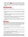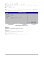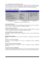
1
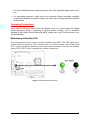
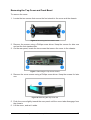
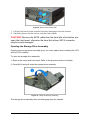
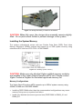
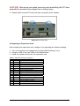
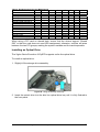
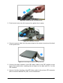
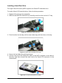
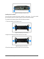
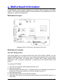
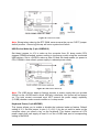
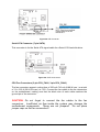
Genie Executive pBTX 915 User Guide C O M P U T E R S . N E T W O R K S . S O L U T I O N S Viglen EMC and the ‘CE’ mark CE Marking As we begin the 21st century, European standards are being harmonised across borders. If products comply with the same standards in all European countries, product exporting and importing is made simple - paving our way to a common market. If you buy a product with a 'CE' mark on it (shown below), on the box, in the manual, or on the guarantee - it complies with the currently enforced directive(s). Introduction to EMC EMC (Electromagnetic Compatibility) is the term used to describe certain issues with RF (Radio Frequency) energy. Electrical items should be designed so they do not interfere with each other through RF emissions. E.g. If you turn on your microwave, your television shouldn't display interference if both items are CE marked to the EMC directive. If emitted RF energy is not kept low, it can interfere with other electrical circuitry - E.g. Cars Automatic Braking Systems have been known to activate by themselves while in a strong RF field. As this has obvious repercussions ALL electrical products likely to cause RF related problems have to be 'CE' marked from 1st January 1996 onwards. If a product conforms to the EMC directive, not only should its RF emissions be very low, but its immunity to RF energy (and other types) should be high. The apparatus has to resist many 'real world' phenomena such as static shocks and mains voltage transients. Viglen’s Environment laboratory To gain a 'CE' mark, the Viglen computer range has had to undergo many difficult tests to ensure it is Electromagnetically Compatible. These are carried out in the in-house 'Environment lab' at Viglen Headquarters. We have made every effort to guarantee that each computer leaving our factory complies fully with the correct standards. To ensure the computer system maintains compliance throughout its functional life, it is essential you follow these guidelines. ¾ ¾ Install the system according to Viglen’s instructions If you open up your Viglen: ¾ ¾ ¾ ¾ ¾ ¾ Keep internal cabling in place as supplied. Ensure the lid is tightly secured afterwards Do not remove drive bay shields unless installing a 'CE' marked peripheral in its place The clips or ‘bumps' around the lips of the case increase conductivity - do not remove or damage. Do not remove the ferrite ring from the L.E.D cables. Only use your Viglen computer with 'CE' marked peripherals This system has been tested in accordance with European standards for use in residential and light industrial areas-this specifies a 10 meter testing radius for emissions and immunity. If you do experience any adverse affects that you think might be related to your computer, try moving it at least 10 meters away from the affected item. If you still experience problems, contact Viglen’s Technical Support department who will put you straight through to an EMC engineer - s/he will do everything possible to help. If modifications are made to your Viglen computer system, it might breach EMC regulations. Viglen take no responsibility (with regards to EMC characteristics) of equipment that has been tampered with or modified. This symbol on the product or on its packaging indicates that the product shall not be treated as household waste. Instead it shall be handed over to the applicable collection point for recycling of electrical and electronic equipment. By ensuring this product is disposed of correctly, you will help prevent potential negative consequences for the environment and human health, which could otherwise be caused by inappropriate waste handling of this product. The recycling of materials will help to conserve natural resources. For more detailed information about recycling of this product, please contact your local city office, your household waste disposal service or Viglen Ltd. Viglen Genie Executive pBTX 915 User Guide V1.0 1 Copyrights and Trademarks Please note: The material in this manual is subject to change without notice. Trademarks Microsoft, Windows, Windows NT, Windows 95,Windows 98, Windows ME, Windows 2000 Pro, Windows XP Pro and MS-DOS are registered trademarks of Microsoft Corporation. IBM PC, XT, AT and PS/2 are trademarks of International Business Machines Corporation. Pentium® and Pentium® Pro are registered trademarks of Intel® Corporation. All other trademarks are acknowledged. JAC-UP, Genie, Contender, Dossier, Vig, Viglen, and Envy are trademarks of Viglen Limited. Copyright and Patents This manual and all accompanying software and documentation are copyrighted and all rights reserved. This product, including software and documentation, may not, in whole or in part, be copied, photocopied, translated or reduced to any electronic or machine-readable form, without prior written consent except for copies retained by the purchaser for backup. © Copyright 2006 Viglen Limited All Rights Reserved Genie Executive 915 pBTX User Guide V1.0 Printed in the United Kingdom Liability No warranty or representation, either expressed or implied, is made with respect to this documentation, its quality, performance, merchantability or fitness for a particular purpose. As a result the documentation is licensed as is, and you, the licensee, are assuming the entire risk as to its quality and performance. The vendor reserves the right to revise this operation manual and all accompanying software and documentation and to make changes in the content without obligation to notify any person or organisation of the revision or change. In no event will the vendor be liable for direct, indirect, special, incidental or consequential damages arising out of the use or inability to use this product or documentation, even if advised of the possibility of such damages. In particular, the vendor shall not have liability for any hardware, software or data stored or used with the product, including the costs of repairing, replacing or recovering such hardware, software or data. Viglen Genie Executive pBTX 915 User Guide V1.0 2 Contents 1. Overview 5 2. System Introduction 6 Viglen Genie Executive pBTX Front Panel Viglen Genie Executive pBTX Rear Panel Viglen Genie Executive pBTX Internal Components Desktop and Tower Configurations 3. Basic Installation Basic Components to Install Before You Proceed Motherboard Standby LED Removing the Top Cover and Front Bezel Opening the Storage Drive Assembly Installing the System Memory Installing and Removing Memory Uninstalling the CPU Heatsink Installing the CPU Notes on Intel Hyper-Threading Technology Reinstalling the CPU Heatsink Expansion Slots Installing an Optical Drive Installing a Hard Disk Drive Replacing the Front Bezel and Top Cover 6 7 8 9 10 10 10 12 13 14 15 16 17 18 20 20 21 25 27 28 4. Motherboard Information 30 Motherboard Layout Motherboard Jumpers Connectors 30 30 32 5. System BIOS BIOS Setup Program BIOS Menu Screen Navigation Keys Main Menu System Information Viglen Genie Executive pBTX 915 User Guide V1.0 38 38 39 39 40 43 3 Advanced Menu USB Configuration CPU Configuration Chipset Onboard Devices Configuration PCIPnP Power Menu AMP Configuration Hardware Monitor Boot Menu Boot Settings Configuration Security Exit Menu 6. Troubleshooting What to do if the system doesn’t work 44 44 45 46 47 48 49 50 51 52 53 54 55 57 57 7. Glossary 60 8. Notes 65 9. Suggestions 69 Viglen Genie Executive pBTX 915 User Guide V1.0 4 1. Overview This manual describes the Viglen Genie Executive 915 pBTX system. The motherboard is the most important part of your computer; it contains all of the CPU, memory and graphics circuitry that makes the Genie Executive pBTX work. Checklist Please check that the following items have been included with your product. If anything listed here is damaged or missing, contact Viglen immediately. In addition to the motherboard and chassis, various hardware components may have been included with your Viglen Genie Executive 915 pBTX, as listed below: • • • • • • • Main system unit AC power cord Keyboard Mouse Microsoft Windows 2000/XP licence sticker and manual(s) Viglen Driver CD Two feet for tower configuration If you have purchased any alternative or optional products along with your system, they will be included with the package along with appropriate support documentation. Congratulations on purchasing your Viglen Genie Executive pBTX system. This User Guide provides you with the information required to set up and use your Personal Computer system. It should be read in conjunction with the accompanying peripheral manuals. Your Viglen Genie Executive pBTX is based on, and is compatible with; the IBM Personal Computer and thus a vast range of software and add-on hardware products are available for use. The system comes preconfigured with either Microsoft Windows 2000 or XP Operating systems. More information can be found in the accompanying manuals. There is a glossary at the end of this manual to explain unfamiliar computer jargon. Viglen Genie Executive pBTX 915 User Guide V1.0 5 2. System Introduction This chapter gives a general description of the Viglen Genie Executive 915 pBTX system. It includes introduction on the front and rear panel features, and the internal features. The Genie Executive 915 pBTX is a book-size system that delivers power and performance in a light and compact package. This portable heavyweight is powered by a Viglen motherboard that supports Intel® Celeron® D/Pentium® 4 processors in the LGA775 package, 800 MHz front side bus, and up to 2GB system memory. The Viglen Genie Executive 915 pBTX features extensive connectivity with its support for up to four USB 2.0 ports. Its Fast Ethernet LAN ensures you stay connected for an enhanced business and personal computing experience. With these and more, the Genie Executive 915 pBTX delivers no less than the powerhouse performance you require. Viglen Genie Executive pBTX Front Panel Figure 1: Front Panel 1. 2. 3. 4. 5. 6. 7. 8. 9. Optical drive bay. This bay is for a slim type optical drive. Floppy disk drive. This bay is for a 1.44 MB slim type floppy disk drive. Power LED. This LED lights up to indicate that the system is on. HDD LED. This LED lights up when data is being read from or written to the hard disk drive. USB 2.0 ports. These Universal Serial Bus 2.0 (USB 2.0) ports are available for connecting USB 2.0 devices such as a mouse, printer, scanner, camera, PDA, and others. Headphone port (Green). This port connects a headphone with a stereo miniplug. Microphone port (Pink). This port connects a microphone. Power button. Press this button to turn the system on or off. Chassis fan vent. This vent is for the fans that provide ventilation inside the system chassis. Viglen Genie Executive pBTX 915 User Guide V1.0 6 Viglen Genie Executive pBTX Rear Panel The system rear panel includes the power socket and several I/O ports that allow convenient connection of devices. Figure 2: Rear Panel 1. Cover screws. These screws secure the system cover. 2. Expansion slot. You can insert a PCI expansion board into this slot to add memory and graphics capabilities to the system. 3. Parallel port. This 25-pin port connects a parallel printer, a scanner, or other devices. 4. PS/2 mouse port (Green). This port is for a PS/2 mouse. 5. Line In port (Light Blue). This port connects a tape, CD, DVD player, or other audio sources. 6. Power socket. This socket connects the power cord. 7. USB 2.0 ports. These Universal Serial Bus 2.0 (USB 2.0) ports are available for connecting USB 2.0 devices such as a mouse, printer, scanner, camera, PDA, and others. 8. LAN (RJ-45) port. This port allows connection to a Local Area Network (LAN) through a network hub. 9. Serial ports. These ports connect a mouse, modem, or other devices that conform to serial specification. 10. PS/2 keyboard port. This purple 6-pin connector is for a PS/2 keyboard. 11. Optical S/PDIF Out port. This port connects an external audio output device via an optical S/PDIF cable. 12. Line Out port (Lime). This port connects a headphone or a speaker. 13. Power supply unit fan vent. This vent is for the PSU fan that provides ventilation inside the power supply unit. Viglen Genie Executive pBTX 915 User Guide V1.0 7 Viglen Genie Executive pBTX Internal Components Figure 3 below shows the internal view of the system when you remove the top cover. The installed components are labelled for your reference. Proceed to Chapter 3 for instructions on installing other system components. Figure 3: Internal Components 1. 2. 3. 4. 5. PCI riser Power supply unit Chassis fan cage Motherboard Storage drive assembly Viglen Genie Executive pBTX 915 User Guide V1.0 8 Desktop and Tower Configurations The Viglen Genie Executive 915 pBTX system is ergonomically designed to save space and complement your desktop. You may use the foot stands provided to place the system vertically in a tower configuration on a flat and stable surface. Please see below for the tower configuration configurations Figure 4: Tower Configuration using the feet provided Viglen Genie Executive pBTX 915 User Guide V1.0 9 3. Basic Installation This chapter provides step by step instructions on how to install components in the system. Basic Components to Install 1. 2. 3. 4. 5. 6. Central processing unit (CPU) CPU heatsink DDR Dual Inline Memory Module Expansion card Hard disk drive Slim type optical drive Tools Required: Philips (cross) screw driver. Before You Proceed Electrical Safety Precautions • Basic electrical safety precautions should be followed to protect you from harm and the Viglen Genie Executive 915 pBTX from damage: • Be aware of the locations of the power on/off switch on the chassis as well as the room's emergency power-off switch, disconnection switch or electrical outlet. If an electrical accident occurs, you can then quickly remove power from the system. • Do not work alone when working with high voltage components. • Power should always be disconnected from the system when removing or installing main system components, such as the motherboard, memory modules and the CD-ROM and floppy drives. When disconnecting power, you should first power down the system with the operating system and then unplug the power cords of all the power supply units in the system. • When working around exposed electrical circuits, another person who is familiar with the power-off controls should be nearby to switch off the power if necessary. • Use only one hand when working with powered-on electrical equipment. This is to avoid making a complete circuit, which will cause electrical shock. Use extreme caution when using metal tools, which can easily damage any electrical components or circuit boards they come into contact with. • Do not use mats designed to decrease electrostatic discharge as protection from electrical shock. Instead, use rubber mats that have been specifically designed as electrical insulators. The power supply power cord must include a grounding plug and must be plugged into grounded electrical outlets. • Viglen Genie Executive pBTX 915 User Guide V1.0 10 • Motherboard Battery: CAUTION - There is a danger of explosion if the onboard battery is installed upside down, which will reverse its polarities. On the Genie Executive pBTX, the positive side should be facing up. This battery must be replaced only with the same or an equivalent type recommended by the manufacturer. Dispose of used batteries according to the manufacturer's instructions. General Safety Precautions Follow these rules to ensure general safety: • Keep the area around the Viglen Genie Executive 915 pBTX clean and free of clutter. • Place the chassis top cover and any system components that have been removed away from the system or on a table so that they won't accidentally be stepped on. • While working on the system, do not wear loose clothing such as neckties and unbuttoned shirt sleeves, which can come into contact with electrical circuits or be pulled into a cooling fan. • Remove any jewelry or metal objects from your body, which are excellent metal conductors that can create short circuits and harm you if they come into contact with printed circuit boards or areas where power is present. • After accessing the inside of the system, close the system back up and secure it to the rack unit with the retention screws after ensuring that all connections have been made. ESD Precautions Electrostatic discharge (ESD) is generated by two objects with different electrical charges coming into contact with each other. An electrical discharge is created to neutralise this difference, which can damage electronic components and printed circuit boards. The following measures are generally sufficient to neutralise this difference before contact is made to protect your equipment from ESD: • Use a grounded wrist strap designed to prevent static discharge. • Keep all components and printed circuit boards (PCBs) in their antistatic bags until ready for use. • Touch a grounded metal object before removing the board from the antistatic bag. • Do not let components or PCBs come into contact with your clothing, which may retain a charge even if you are wearing a wrist strap. Handle a board by its edges only; do not touch its components, peripheral chips, memory modules or contacts. When handling chips or modules, avoid touching their pins. • • Viglen Genie Executive pBTX 915 User Guide V1.0 11 • Put the motherboard and peripherals back into their antistatic bags when not in use. • For grounding purposes, make sure your computer chassis provides excellent conductivity between the power supply, the case, the mounting fasteners and the motherboard. Operating Precautions Care must be taken to assure that the chassis cover is in place when the Viglen Genie Executive pBTX is operating to assure proper cooling. Out of warranty damage to the Viglen Genie Executive pBTX system can occur if this practice is not strictly followed. Motherboard Standby LED The motherboard comes with an onboard standby power LED. This LED lights up to indicate that the system is ON, in sleep mode or in soft-off mode, and not powered OFF. Unplug the power cable from the power outlet and make sure that the standby power LED is OFF before installing any system component. Figure 5: Motherboard Standby LED Viglen Genie Executive pBTX 915 User Guide V1.0 12 Removing the Top Cover and Front Bezel To remove the cover: 1. Locate the two screws that secure the foot stands to the cover and the chassis. Figure 6: Removing the foot stand screws 2. Remove the screws using a Phillips screw driver. Keep the screws for later use and set the foot stands aside. 3. On the rear panel, locate the two screws that secure the cover to the chassis. Figure 7: Removing the Top Cover Screws 4. Remove the cover screws using a Phillips screw driver. Keep the screws for later use. Figure 8: Removing the Top Cover Lid 5. Push the cover slightly toward the rear panel until the cover tabs disengage from the chassis. 6. Lift the cover, and set it aside. Viglen Genie Executive pBTX 915 User Guide V1.0 13 Figure 9: Remove the Front Panel 7. Lift the front bezel hooks outward until they disengage from the chassis. 8. Carefully remove the front cover, and then set it aside. CAUTION: Remove the SATA cable from the hard disk drive before you open the front bezel, otherwise the hard disk drives SATA connector may be easily damaged. Opening the Storage Drive Assembly Opening the storage drive assembly gives you more space when installing the CPU and the CPU heatsink. To open the storage drive assembly: 1. Remove the cover and front bezel. Refer to the previous section for details. 2. Carefully lift and pull down the storage drive assembly Figure 10: Lifting the Storage Assembly The storage drive assembly does not disengage from the chassis Viglen Genie Executive pBTX 915 User Guide V1.0 14 Figure 11: Storage Assembly in maximum Orientation CAUTION: When fully open, the storage drive assembly remains slightly tilted. Do not push down further to prevent damage to the system. Installing the System Memory The system motherboard comes with two Double Data Rate (DDR) Dual Inline Memory Module(s) (DIMM) sockets that support up to 2GB system memory using unbuffered ECC and non-ECC PC32--/2700 DIMMS. Figure 12: Installing System memory CAUTION: Make sure only identical Viglen certified memory modules are installed in the Viglen Genie Executive pBTX unit. Please contact Viglen Technical Support for the latest approved memory list. Memory Configurations The Viglen Genie Executive pBTX supports up to 2GB of system memory using 256Mb, 512MB and 1GB DDR DIMMs. • • Installing DDR DIMMs other than the recommended configurations may cause memory sizing error or system boot failure. Install only identical (the same type and size) DDR DIMM in DIMM_A1 and DIMM_B1. Viglen Genie Executive pBTX 915 User Guide V1.0 15 • • • Always install DIMMs with the same CAS latency. For optimum compatibility, we recommend that you obtain memory modules from Viglen Ltd to guarantee consistency in product. Due to chipset resource allocation, the system may detect less than 2GB system memory when you installed two 1GB DDR memory. This motherboard does not support memory modules made up of 128Mb chips or double-sided x16 memory modules. Installing and Removing Memory Installing Memory 1. Observe the precautions in “Upgrading and ESD precautions”. Turn off the computer and all peripheral devices. 2. Remove the computer cover and locate the DIMM sockets. 3. Holding the DIMM by the edges, remove it from its antistatic package. 4. Make sure the clips at either end of the socket are pushed away from the socket. 5. Position the DIMM above the socket. Align the two small notches in the bottom edge of the DIMM with the keys in the socket. Insert the bottom edge of the DIMM into the socket. 6. When the DIMM is seated, push down on the top edge of the DIMM until the retaining clips at the ends of the socket snap into place. Make sure the clips are firmly in place. 7. Replace the computer cover. Removing Memory 1. To remove a DIMM, follow these steps: 2. Observe the precautions in “Upgrading and ESD precautions”. 3. Turn off all peripheral devices connected to the computer. Turn off the computer. 4. Remove the computer cover. 5. Gently spread the retaining clips at each end of the socket. The DIMM pops out of the socket. Hold the DIMM by the edges, lift it away from the socket, and store it in an antistatic package. 6. Reinstall and reconnect any parts you removed or disconnected to reach the DIMM sockets. Viglen Genie Executive pBTX 915 User Guide V1.0 16 Figure 13: Removing DIMMs Uninstalling the CPU Heatsink You need to remove the proprietary CPU heatsink assembly from the motherboard before you can install a CPU. To uninstall the CPU heatsink: 1. Open the storage drive assembly. Refer to the previous section for details. 2. Using a Philips screw driver, remove the four screws that secure the CPU heatsink to the motherboard. Figure 14: Unscrewing the Heatsink 3. Lift the CPU heatsink, and then set it aside. Viglen Genie Executive pBTX 915 User Guide V1.0 17 Installing the CPU To install a CPU: 1. Locate the CPU socket on the motherboard. Figure 15: CPU Socket 775 Location Note: Before installing the CPU, make sure that the cam box is facing towards you and the load lever is on your left. 2. Press the load lever with your thumb (a), then move it to the left (b) until it is released from the retention tab. Figure 16: Pressing the Load Lever CAUTION: To prevent damage to the socket pins, do not remove the PnP cap unless you are installing a CPU. 3. Lift the load lever in the direction of the arrow to a 135° angle. Figure 17: Lift the Load Lever Viglen Genie Executive pBTX 915 User Guide V1.0 18 4. Lift the load plate with your thumb and forefinger to a 100º angle (A), then push the PnP cap from the load plate window to remove (B). Figure 18: Lifting the Load Plate 5. Position the CPU over the socket, making sure that the gold triangle is on the bottom-left corner of the socket. The socket alignment key should fit into the CPU notch. Figure19: Positioning the CPU 6. Close the load plate (A), then push the load lever (B) until it snaps into the retention tab. Figure 20: Closing the Load Plate Viglen Genie Executive pBTX 915 User Guide V1.0 19 CAUTION: The CPU fits in only one correct orientation. DO NOT force the CPU into the socket to prevent bending the connectors on the socket and damaging the CPU! Notes on Intel® Hyper-Threading Technology • This motherboard supports Intel® Pentium® 4 CPUs in the 775-land package with Hyper-Threading Technology. • Hyper-Threading Technology is supported under Windows® XP and Linux 2.4.x (kernel) and later versions only. Under Linux, use the Hyper-Threading compiler to compile the code. If you are using any other operating systems, disable the Hyper-Threading Technology item in the BIOS to ensure system stability and performance. • Installing Windows® XP Service Pack 2 is recommended. • Make sure to enable the Hyper-Threading Technology item in BIOS before installing a supported operating system. • For more information on Hyper-Threading Technology, visit: www.intel.com/info/hyperthreading To use the Hyper-Threading Technology on this motherboard: 1. Install an Intel® Pentium® 4 CPU that supports Hyper-Threading Technology. 2. Power up the system and enter the BIOS Setup. Under the Advanced Menu, make sure that the item Hyper-Threading Technology is set to Enabled. The item appears only if you installed a CPU that supports Hyper-Threading Technology. 3. Reboot the computer. Reinstalling the CPU Heatsink To reinstall the CPU heatsink: 1. Position the heatsink on top of the installed CPU; make sure that the four fasteners match the holes on the motherboard. CAUTION: Please make sure that the current thermal paste has been removed and new paste has been applied evenly on the CPU. 2. Using a Philips screw driver, secure the CPU heatsink assembly to the motherboard with the four screws you removed earlier. Viglen Genie Executive pBTX 915 User Guide V1.0 20 Figure 21: Reinstalling the Heatsink 3. Close the storage drive assembly. CAUTION: Please make sure that the CPU fan connectors are plugged in. Hardware monitoring errors may occur if you fail to plug this connector. Expansion Slots In the future, you may need to install an expansion card. The following sub-sections describe the slots and the expansion cards that they support. CAUTION: Make sure to unplug the power cord before adding or removing expansion cards. Failure to do so may cause you physical injury and damage motherboard components. PCI Slot The PCI slot supports cards such as a LAN card, SCSI card, USB card and other cards that comply with PCI specifications. Installing a PCI Card To install a PCI Card please follow the below procedures: 1. Before installing the expansion card, read the documentation that came with it and make the necessary hardware settings for the card. 2. Remove the system unit cover. 3. Carefully lift the PCI riser assembly unit it disengages from the chassis. Viglen Genie Executive pBTX 915 User Guide V1.0 21 Figure 22: Lifting the Riser Assembly 4. Place the PCI riser on a flat surface Figure 23: PCI Riser Assembly 5. Remove the screw securing the card slot cover (see Figure 24). Keep the screw for later use. 6. Align the PCI card connector with the slot and press firmly until the card is completely seated on the slot. Viglen Genie Executive pBTX 915 User Guide V1.0 22 Figure 24: Installing the PCI Card 7. Secure the card to the PCI riser assembly with the screw you removed earlier. Figure 25: Securing the PCI card to the Riser Assembly 8. Reinstall the PCI riser to the system chassis. Figure 26: Reinstalling the PCI riser Viglen Genie Executive pBTX 915 User Guide V1.0 23 CAUTION: Take extra care when removing and reinstalling the PCI riser assembly to prevent sharp edges from causing injury. 9. Please make sure the PCI riser side tabs completely fit the chassis. Figure 27: PCI Riser Tabs Configuring an Expansion Card After installing the expansion card, configure it by adjusting the software settings. 1. Turn on the system and change the necessary BIOS settings, if any. 2. Assign an IRQ to the card. Refer to the tables below. 3. Install the software drivers for the expansion card. Table 1: Standard Interrupt Assignment IRQ Priority Standard 0 1 System Timer 1 2 Keyboard Controller 2 Re-direct to IRQ#9 3 11 Communication Port (COM2)* 4 12 Communication Port (COM1)* 5 13 IRQ holder for PCI steering* 6 14 Floppy Disk Controller 7 15 Printer Port (LPT1)* 8 3 System CMOS/Real Time Clock 9 4 IRQ holder for PCI steering* 10 5 IRQ holder for PCI steering* 11 6 IRQ holder for PCI steering* 12 7 PS/2 Compatible Mouse Port* 13 8 Numeric Data Processor 14 9 Primary IDE controller 15 10 Secondary IDE controller * There IRQs are usually available for ISA or PCI devices Viglen Genie Executive pBTX 915 User Guide V1.0 24 Table 2: IRQ Assignment for this Motherboard A B C PCI slot 1 PCI slot 2 PCI Express x16 slot shared PCI Express x1 slot shared Onboard USB controller 1 Onboard USB controller 2 Onboard USB controller 3 shared Onboard USB controller 4 shared Onboard USB 2.0 controller Onboard Azalia Audio shared Onboard IDE Controller shared Onboard SATA Controller Onboard LAN Onboard PCI IDE (ITE) - D shared shared - E shared shared F used - G used - H shared shared - When using a PCI card on shared slots, ensure that the drivers support “Shared IRQ” or that the card does not need IRQ assignment; otherwise, conflicts will arise between the two PCI groups, making the system unstable and the card inoperable. Installing an Optical Drive The Viglen Genie Executive 915 pBTX supports a slim line optical drive. To install an optical drive: 1. Slightly lift the storage drive assembly. Figure 28: Lifting the Storage Assembly 2. Insert the optical drive into the slim line optical drive bay unit it is fully flushed to the front panel. Viglen Genie Executive pBTX 915 User Guide V1.0 25 Figure 29: Installing the Slim Line Optical Drive 3. Push the lock tab to the left to secure the optical drive in place. Figure 30: Pushing the Lock Tab 4. Connect a power cable from the power supply to the power connector at the back of the optical drive. Figure 31: Connecting the Cables to the Optical Drive 5. Connect the black interface of the IDE ribbon cable to the IDE interface at the back of the optical drive, matching the red stripe on the cable with Pin 1 on the IDE interface. 6. Connect the blue interface of the IDE ribbon cable to the primary IDE connector (Blue connector labelled PRI_IDE) on the motherboard. Viglen Genie Executive pBTX 915 User Guide V1.0 26 Installing a Hard Disk Drive The Viglen Genie Executive pBTX supports one Serial ATA hard disk drive. To install a Serial ATA hard disk drive, follow the below procedure: 1. Slightly lift the storage drive assembly. 2. With the hard disk drive label side up, carefully insert the drive into the 3.5” bay. Figure 32: Inserting the Hard Disk Drive 3. Push the drive into the bay until its screw holes align with the holes on the bay. Figure 33: Aligning the Hard Disk Drive Holes 4. Secure the hard disk drive with two screws. 5. Connect one end of the Serial ATA cable to the SATA connector at the back of the drive, and then connect the other end to the Serial ATA connector on the motherboard. Figure 34: Connecting the Serial ATA Cable Viglen Genie Executive pBTX 915 User Guide V1.0 27 6. Connect a 15-pin Serial ATA power plug from the power supply unit to the power connector at the back of the drive. Or connect a 4-pin (female) power plug from the power supply unit to the 4-pin (male) power connector at the back of the drive. CAUTION: If the Serial ATA hard disk drive has both 4-pin and 15-pin connectors at the back, use either the 15-pin Serial ATA power adapter plug or the legacy 4-pin power connector. DO NOT use both to prevent damage to components and to keep the system from becoming unstable. Replacing the Front Bezel and Top Cover After installing all system components and connecting all the cables, replace the front bezel and system cover by following these instructions. 1. Fasten the front bezel hooks to the chassis holes until they fit in place. Figure 35: Reinstalling the Front Bezel 2. Position the cover at least two inches from the front panel, and then align the cover hooks to the chassis rail. Figure 36: Reinstalling the Top Cover 3. Push the system cover towards the front panel until it fits in place. 4. Secure the system cover with the screws you removed earlier. Viglen Genie Executive pBTX 915 User Guide V1.0 28 Figure 37: Reinstalling the system screws Installing the Foot Stand You may prefer to position the system vertically to save space. You must reinstall the foot stands to place the system upright to prevent accidental damage. To reinstall the foot stands, please follow the below procedure: 1. Fit the foot stands on the chassis cover. Figure 38: Reattaching the Foot Stands 2. Align the foot stand screw holes with the cover holes. Figure 39: Aligning the Screw Holes 3. Drive the screws you removed earlier into the screw holes. Viglen Genie Executive pBTX 915 User Guide V1.0 29 4. Motherboard Information A Motherboard comes already installed in the Viglen Genie Executive 915 pBTX system. This section provides technical information about the motherboard for future upgrades or system reconfiguration. Motherboard Layout Figure 40: Viglen Genie Executive pBTX Motherboard Layout Motherboard Jumpers Clear RTC RAM (CLRTC) This jumper allows you to clear the Real Time Clock (RTC) RAM in CMOS. You can clear the CMOS memory of date, time, and system setup parameters by erasing the CMOS RTC RAM data. The RAM data in CMOS, that include system setup information such as system passwords, is powered by the onboard button cell battery. To erase the RTC RAM: 1. Turn OFF the computer and unplug the power cord. 2. Remove the battery. 3. Move the jumper cap from pins 1-2 (default) to pins 2-3. Keep the cap on pins 2-3 for about 5-10 seconds, and then move the cap back to pins 1-2. 4. Re-install the battery. 5. Plug the power cord and turn ON the computer. 6. Hold down the <Del> key during the boot process and enter BIOS setup to reenter data. Viglen Genie Executive pBTX 915 User Guide V1.0 30 Figure 41: Clear RTC RAM Note: Except when clearing the RTC RAM, never remove the cap on CLRTC jumper default position. Removing the cap will cause system boot failure. USB Device Wake-Up (3-pin USBPW12) Set these jumpers to +5V to wake up the computer from S1 sleep mode (CPU stopped, DRAM refreshed, system running in low power mode) using the connected USB devices. Set to +5VSB to wake up from S3 and S4 sleep modes (no power to CPU, DRAM in slow refresh, power supply in reduced power mode). Figure 42: USB Device Wake-Up Note: The USB device wake-up feature requires a power supply that can provide 500mA on the +5VSB lead for each USB port; otherwise, the system will not power up. The total current consumed must NOT exceed the power supply capability (+5VSB) whether under normal condition or in sleep mode. Keyboard Power (3-pin KBPWR) This jumper allows you to enable or disable the keyboard wake-up feature. Default setting is 2-3. Set this jumper to pins 1-2 (+5V) if you do not want to wake up the computer when you press a key on the keyboard. This feature requires an ATX power supply that can supply at least 1A on the +5VSB lead, and a corresponding setting in the BIOS. Viglen Genie Executive pBTX 915 User Guide V1.0 31 Figure 43: Keyboard Power Setting Connectors Floppy Disk Drive Connector This connector is for the provided floppy disk drive (FDD) signal cable. Insert one end of the cable to this connector, and then connect the other end to the signal connector at the back of the floppy disk drive. Figure 44: Floppy Disk Drive Connector Primary IDE Connector (40-1 pin PRI_IDE) This connector is for an Ultra DMA 100/66 signal cable. The Ultra DMA 100/66 signal cable has two connectors: a blue connector for the primary IDE connector on the motherboard and a black connector for an Ultra DMA 100/66 IDE slave device (optical drive/hard disk drive). Note: Pin 20 on the IDE connector is removed to match the covered hole on the Ultra DMA cable connector. This prevents incorrect insertion when you connect the IDE cable. Use the 80-conductor IDE cable for Ultra 100/66 IDE device. Viglen Genie Executive pBTX 915 User Guide V1.0 32 Figure 45: IDE Connector Serial ATA Connector (7-pin SATA) This connector is for the Serial ATA signal cable for a Serial ATA hard disk drive. Figure 46: SATA Connectors CPU Fan Connectors (3-pin CPU_FAN1, 3-pin CPU_FAN2) The fan connectors support cooling fans of 350 mA~740 mA (8.88 W max.) or a total of 1 A~2.22 A (26.64 W max.) at +12V. Connect the fan cables to the fan connectors on the motherboard, making sure that the black wire of each cable matches the ground pin of the connector. CAUTION: Do not forget to connect the fan cables to the fan connectors. Insufficient air flow inside the system may damage the motherboard components. These are not jumpers!! Do not place jumper caps on the fan connectors!! Viglen Genie Executive pBTX 915 User Guide V1.0 33 Figure 47: CPU Fan Connectors ATX Power Connectors (20-pin ATXPWR, 4-pin ATX12V) These connectors are for ATX power supply plugs. The plugs from the power supply are designed to fit these connectors in only one orientation. Find the proper orientation and push down firmly until the connectors completely fit. Figure 48: ATX Power Connector Important Notes on the motherboard power requirements: • • • • Do not forget to connect the 4-pin ATX +12V power plug; otherwise, the system will not boot up. To power the motherboard, it is recommended that you use an ATX 12V Specification 2.0 power supply unit (PSU) with a minimum 230W power rating. This PSU type has a 20-pin and 4-pin ATX power plugs. Make sure that the 20-pin power plug can provide at least 16A on +12V and that the PSU has a minimum power rating of 230W. The system may become unstable or may not boot up if the power is inadequate. You must install a PSU with a higher power rating if you intend to install additional devices. USB Connector (10-1 pin USB56, USB78) Viglen Genie Executive pBTX 915 User Guide V1.0 34 These connectors are for the USB device module. Figure 49: USB 2.0 Connectors CAUTION: Never connect an IEEE-1394 cable to the USB connector. Doing so will damage the motherboard. Optical Drive Audio Connector (4-pin CD) This connector is for the 4-pin audio cable that connects to the audio connector at the back of the optical drive. Figure 50: Internal Audio connector Note: Use this connector only if the optical drive has an analog audio output. Front Panel Audio Connector (10-1 pin AAFP) This connector is for a chassis-mounted front panel audio I/O module. Viglen Genie Executive pBTX 915 User Guide V1.0 35 Figure 51: Front Panel Audio Connector System Panel Connector (12-1 pin CONTROL) This connector supports several chassis-mounted functions. Figure 52: System Panel Connector Hard Disk Drive Activity LED (2-pin HDD_LED) This 2-pin connector is for the hard disk drive activity LED. Connect the hard disk drive activity LED cable to this connector. The IDE LED lights up or flashes when data is read from or written to the hard disk drive. ATX Power Button/Soft-Off Button (2-pin POWER_BUTTON) This connector is for the system power button. Pressing the power button turns the system on or puts the system in sleep or soft-off mode depending on the BIOS settings. Pressing the power switch for more than four seconds while the system is ON turns the system off. Reset Button (2-pin RESET) This 2-pin connector is for the chassis-mounted reset button for system reboot without turning of the system power. CD-ROM LED (2-pin CDROM_LED) This 2-pin connector is for the optical drive activity LED. The LED lights up or flashes when the optical drive is in use. Viglen Genie Executive pBTX 915 User Guide V1.0 36 Power LED (2-pin POWER_LED) This 2-pin connector is for the power LED. The LED lights up when system power is on. Suspend LED (2-pin SUSPEND_LED) This 2-pin connector is for the suspend LED. The LED lights up when the system is in suspend mode. Viglen Genie Executive pBTX 915 User Guide V1.0 37 5. System BIOS BIOS Setup Program This motherboard supports a programmable firmware chip that you can update using the Viglen supplied utility. Use the BIOS setup program when you are installing a motherboard, reconfiguring you system, or prompted to “Run Setup”. This section explains how to configure you system using this utility. Even if you are not prompted to use the Setup Program, you can change the configuration of you computer in the future. For example, you can enable the security password feature or change the power management settings. This requires you to reconfigure you system using the BIOS Setup program so that the computer can recognise these changes and record then in the CMOS RAM of the firmware hub. The firmware hub on the motherboard stores the Setup utility. When you start up the computer, the system provides you with the opportunity to run this program. Press <Del> during Power-On-Self-Test (POST) to enter the Setup Utility; otherwise, POST continues with its test routines. If you wish to enter Setup after POST, restart the system by pressing <Ctrl+Alt+Del>, or by pressing the reset button on the system chassis. You can also restart by turning the system off and then back on. Do this last option only if the first two fail. The Setup Program is designed to make it easy to use as possible. Being a menudriven program, it lets you scroll through the various sub-menus and make you selections from the available options using the navigation keys. Note: 1. The default BIOS settings for this motherboard apply for most conditions to ensure optimum performance. If the system becomes unstable after changing any BIOS settings, load the default settings to ensure system compatibility and stability. Select the Load Default Settings item under the Exit Menu. 2. The BIOS setup screens shown in this section are for reference purposes only, and may not exactly match what you see on your screen. Viglen Genie Executive pBTX 915 User Guide V1.0 38 BIOS Menu Screen Figure 53: BIOS Menu Screen Menu Bar The menu bar on top of the screen has the following main items: Table 3: Menu Bar Main For changing the basic system configuration Advanced For changing the advanced system settings Power For changing the advanced power management (APM) configuration Boot For changing the system boot configuration Exit For selecting the exit options and loading default settings To select an item on the menu bar, press the right or left arrow key on the keyboard until the desired item is highlighted. Navigation Keys At the bottom right corner of a menu screen are the navigation keys for that particular menu. Use the navigation keys to select items in the menu and change the settings. Note: Some of the navigation keys differ from one screen to another. Viglen Genie Executive pBTX 915 User Guide V1.0 39 Main Menu When you enter the BIOS Setup program, the Main menu screen appears, giving you an overview of the basic system information. Figure 54: BIOS Main Menu Screen System Time [xx:xx:xx] Allows you to set the system time. System Date [Day xx/xx/xxxx] Allows you to set the system date. Legacy Diskette A [1.44M, 3.5 in.] Sets the type of floppy drive installed. Configuration options: [Disabled] [1.44M, 3.5 in.] Viglen Genie Executive pBTX 915 User Guide V1.0 40 Primary/Third/Fourth IDE Master/Slave While entering Setup, the BIOS automatically detects the presence of IDE devices. There is a separate sub-menu for each IDE device. Select a device item then press <Enter> to display the IDE device information. Figure 55: BIOS Primary IDE Master Screen The BIOS automatically detects the values opposite the dimmed items (Device, Vendor, Size, LBA Mode, Block Mode, PIO Mode, Async DMA, Ultra DMA, and SMART monitoring). These values are not user-configurable. These items show N/A if no IDE device is installed in the system. Type [Auto] Selects the type of IDE drive. Setting to Auto allows automatic selection of the appropriate IDE device type. Select CDROM if you are specifically configuring a CDROM drive. Select ARMD (ATAPI Removable Media Device) if your device is a ZIP, LS-120, or MO drive. Configuration options: [Not Installed] [Auto] [CDROM] [ARMD] LBA/Large Mode [Auto] Enables or disables the LBA mode. Setting to Auto enables the LBA mode if the device supports this mode, and if the device was not previously formatted with LBA mode disabled. Configuration options: [Disabled] [Auto] Block (Multi-sector Transfer) [Auto] Enables or disables data multi-sectors transfers. When set to Auto, the data transfer from and to the device occurs multiple sectors at a time if the device supports multisector transfer feature. When set to [Disabled], the data transfer from and to the device occurs one sector at a time. Configuration options: [Disabled] [Auto] PIO Mode [Auto] Selects the PIO mode. Configuration options: [Auto] [0] [1] [2] [3] [4] DMA Mode [Auto] Selects DMA mode. (auto: auto detected. SWDMAn: singlewordDMAn. MWDMAn: MultiWordMAn.UDMAn: UltraDMAn. Configuration options: [Auto] Viglen Genie Executive pBTX 915 User Guide V1.0 41 SMART Monitoring [Auto] Sets the Smart Monitoring, Analysis, and Reporting Technology. Configuration options: [Auto] [Disabled] [Enabled] 32Bit Data Transfer [Disabled] Enables or disables 32-bit data transfer. Configuration options: [Disabled] [Enabled] IDE Configuration The items in this menu allow you to set or change the configurations for the IDE devices installed in the system. Select an item then press <Enter> if you want to configure the item. Figure 56: IDE Configuration Screen Configure SATA As [Standard IDE] Set SATA controller to IDE mode. Configuration options: [Standard IDE] Onboard IDE Operate Mode [Enhanced Mode] Allows selection of the IDE operation mode depending on the operating system (OS) that you installed. Set to Enhanced Mode if you are using native OS, such as Windows® 2000/XP. Configuration options: [Disabled] [Compatible Mode] [Enhanced Mode] Enhanced Mode Support On [SATA ] Allows you to use native OS on Serial ATA and Parallel ATA ports. In this setting, you may use legacy OS on the Parallel ATA ports only if you did not install any Serial ATA device. Note: The following item appears only when you set the Onboard IDE OperateMode to [Compatible Mode]. Combined Mode Option [Secondary P-ATA+S-ATA] Allows you to use choose the IDE ports to be used. If you select Primary P-ATA+SATA, the system will only support SATA2 and SATA4 in Combined mode. The S-ATA only and P-ATA only options are for advanced users only. If you set to any of these options and encounter problems, revert to the default setting [Secondary P-ATA+S-ATA]. Configuration options: [Secondary P-ATA+S-ATA] [SATA only] [P-ATA only] Viglen Genie Executive pBTX 915 User Guide V1.0 42 IDE Detect Time Out (Sec) [35] Select the time out value for detecting ATA/ATAPI device(s). Configuration options: [0] [5] [10] [15]...[35] System information This menu gives you an overview of the general system specifications. The BIOS automatically detects the items in this menu. Figure 57: System information Screen AMI BIOS Displays the auto-detected BIOS information. Processor Displays the auto-detected CPU specification. Memory Size/Mode/Channel Displays the auto-detected system memory information. Viglen Genie Executive pBTX 915 User Guide V1.0 43 Advanced Menu The Advanced menu items allow you to change the settings for the CPU and other system devices. CAUTION: Take caution when changing the settings of the Advanced Menu items. Incorrect field values can cause the system to malfunction. Figure 58: Advanced Menu Screen. USB Configuration The items in this menu allows you to change the USB-related features. Select an item then press <Enter> to display the configuration options. Figure 59: USB configuration Screen Note: The Module Version and USB Devices Enabled items show the auto-detected values. If no USB device is detected, the item shows none. USB Function [Enabled] Enables USB host controllers. Configuration options: [Disabled] [Enabled] Viglen Genie Executive pBTX 915 User Guide V1.0 44 Legacy USB Support [Auto] Enables support for legacy USB. AUTO option disables legacy support if no USB devices are connected. Configuration options: [Disabled] [Enabled] [Auto] USB 2.0 Controller [Enabled] Allows you to enable or disable the USB 2.0 controller. Configuration options: [Disabled] [Enabled] USB 2.0 Controller Mode [HiSpeed] Configures the USB 2.0 controller in HiSpeed (480Mbps) or FullSpeed (12Mbps). Configuration options: [HiSpeed] [FullSpeed] BIOS EHCI Hand-Off [Enabled] Configuration options: [Disabled] [Enabled] CPU Configuration The items in this menu show the CPU-related information that the BIOS automatically detects. Figure 60: CPU Configuration Screen Execute Disable Function [Disabled] Configuration options: [Disabled] [Enabled] Enhanced C1 Control [Auto] When set to [Auto], the BIOS will automatically check the CPU’s capability to enable the C1E support. In C1E mode, the CPU power consumption is lower when idle. Configuration options: [Auto] [Disabled] CPU Internal Thermal Control [Auto] Disables or sets the CPU internal thermal control. Configuration options: [Auto] [Disabled] Hyper Threading Technology [Enabled] Enables or disables the processor Hyper-Threading technology. Configuration options: [Disabled] [Enabled] Viglen Genie Executive pBTX 915 User Guide V1.0 45 Intel(R) SpeedStep(tm) Tech. [Automatic] Enable/Disable Intel Speed Step Support in BIOS. Configuration options: [Automatic] [Disabled] Chipset The Chipset menu allows you to change the advanced chipset settings. Select an item then press <Enter> to display the sub-menu. Figure 61: Chipset Settings Screen Configure DRAM Timing by SPD [Enabled] When this item is enabled, the DRAM timing parameters are set according to the DRAM SPD (Serial Presence Detect). When disabled, you can manually set the DRAM timing parameters through the DRAM sub-items. Configuration options: [Disabled] [Enabled] Note: The following sub-items appear when Configure DRAM Timing by SPD item is disabled. DRAM CAS# Latency [5 Clocks] Controls the latency between the SDRAM read command and the time the data actually becomes available. Configuration options: [6 Clocks] [5 Clocks] [4 Clocks] [3 Clocks] DRAM RAS# Precharge [4 Clocks] Controls the idle clocks after issuing a precharge command to the DDR SDRAM. Configuration options: [2 Clocks] [3 Clocks] [4 Clocks] [5 Clocks] [6 Clocks] DRAM RAS# to CAS# Delay [4 Clocks] Controls the latency between the DDR SDRAM active command and the read/write command. Configuration options: [2 Clocks] [3 Clocks] [4 Clocks] [5 Clocks] [6 Clocks] DRAM RAS# Activate to Prec [15 Clocks] Configuration options: [4 Clocks] ~ [18 Clocks] Viglen Genie Executive pBTX 915 User Guide V1.0 46 DRAM Write Recovery Time [4 Clocks] Sets the DRAM Burst Length. Configuration options: [2 Clocks]...[8 Clocks] Graphic Adapter Priority [Internal VGA] Select which graphics controller to use as the primary boot device. Configuration options: [Internal VGA] [PCI/Int-VGA] Internal Graphics Mode Selec [Enabled, 8MB] Select the amount of system memory reallocated by the internal graphics device. Configuration options: [Disabled] [Enabled, 1MB] [Enabled, 8MB] Graphic Memory Type [Auto] Select which graphics memory type support. Configuration options: [Auto] [DUMT] [FIX] [DUMT+FIX] Onboard Devices Configuration Figure 62: Onboard Devices Configuration screen HD Audio Controller [Enabled] Enables or disables the HD Audio controller. Configuration options: [Enabled] [Disabled] Onboard PCIEX GbE LAN [Enabled] Enables or disables the onboard PCIE GbE LAN controller. Configuration options: [Enabled] [Disabled] LAN Option ROM [Disabled] Onboard PCIEX GbE LAN boot ROM configuration. Configuration [Disabled] [Enabled] Serial Port1 Address [3F8/IRQ4] Allows you to select the Serial Port1 base address. Configuration options: [Disabled] [3F8/IRQ4] [2F8/IRQ3] [2E8/IRQ3] Viglen Genie Executive pBTX 915 User Guide V1.0 47 Parallel Port Address [378] Allows you to select the Parallel Port base addresses. Configuration options: [Disabled] [378] [278] [3BC] Parallel Port Mode [ECP] Allows you to select the Parallel Port mode. Configuration options: [Normal] [Bidirectional] [EPP] [ECP] ECP Mode DMA Channel [DMA3] Appears only when the Parallel Port Mode is set to [ECP]. This item allows you to set the Parallel Port ECP DMA. Configuration options: [DMA0] [DMA1] [DMA3] Parallel Port IRQ [IRQ7] Allows selection of the Parallel Port IRQ. Configuration options: [IRQ5] [IRQ7] PCIPnP Figure 63: Advanced PCI/PnP settings screen Plug And Play O/S [No] Configuration options: [NO] [YES] Viglen Genie Executive pBTX 915 User Guide V1.0 48 Power Menu The Power menu items allow you to change the settings for the Advanced Power Management (APM) and Advanced Configuration and Power Interface (ACPI). Select an item then press <Enter> to display the configuration options. Figure 64: Power Menu Screen Suspend Mode [Auto] Allows you to select the Advanced Configuration and Power Interface (ACPI) state to be used for system suspend. Configuration options: [S1 (POS) Only] [S3 Only] [Auto] Repost Video on S3 Resume [No] Determines whether to invoke VGA BIOS post on S3/STR resume.Configuration options: [No] [Yes] ACPI 2.0 support [No] Configuration options: [No] [Yes] ACPI APIC Support [Enabled] Allows you to enable or disable the Advanced Configuration and Power Interface (ACPI) support in the Advanced Programmable Interrupt Controller (APIC). When set to Enabled, the ACPI APIC table pointer is included in the RSDT pointer list. Configuration options: [Disabled] [Enabled] Viglen Genie Executive pBTX 915 User Guide V1.0 49 AMP Configuration Figure 65: AMP Configuration Screen Power button Mode [On/Off] Selects going into On/Off or suspend when power button is pressed. Configuration options: [On/Off] [Suspend] Restore on AC Power Loss [Power Off] When set to Power Off, the system goes into off state after an AC power loss. When set to Power On, the system goes on after an AC power loss. When set to Last State, the system goes into either off or on state, whatever the system state was before the AC power loss. Configuration options: [Power Off] [Power On] [Last State] Power On By RTC Alarm [Disabled] Allows you to enable or disable RTC to generate a wake event. When this item is set to Enabled, the items RTC Alarm Date, RTC Alarm Hour, RTC Alarm Minute, and RTC Alarm Second appear with set values. Configuration options: [Disabled] [Enabled] Power On By External Modems [Disabled] This allows either settings of [Enabled] or [Disabled] for powering up the computer when the external modem receives a call while the computer is in Soft-off mode. Configuration options: [Disabled] [Enabled] Note: The computer cannot receive or transmit data until the computer and applications are fully running. Thus, connection cannot be made on the first try. Turning an external modem off and then back on while the computer is off causes an initialization string that turns the system power on. Power On By PCI Devices [Disabled] When set to [Enabled], this parameter allows you to turn on the system through a PCI LAN or modem card. This feature requires an ATX power supply that provides at least 1A on the +5VSB lead. Configuration options: [Disabled] [Enabled] Viglen Genie Executive pBTX 915 User Guide V1.0 50 Power On By PCIE Devices [Disabled] Disable/Enable PCIE to generate a wake event. Configuration options: [Disabled] [Enabled] Power On By PS/2 Keyboard [Disabled] Allows you to use specific keys on the keyboard to turn on the system. This feature requires an ATX power supply that provides at least 1A on the +5VSB lead. Configuration options: [Disabled] [Enabled] Keyboard Wakeup Password This item appears only when the Power On By PS/2 Keyboard is set to Enabled. Select this item to set or change the keyboard wakeup password. The Keyboard Wakeup Password item that appears below shows the default Not Installed. After you have set a password, this item shows Installed. Power On By PS/2 Mouse [Disabled] When set to [Enabled], this parameter allows you to use the PS/2 mouse to turn on the system. This feature requires an ATX power supply that provides at least 1A on the +5VSB lead. Configuration options: [Disabled] [Enabled] Hardware Monitor Figure 66: Hardware Monitor Screen CPU Temperature [xxxºC/xxxºF] & MB Temperature [xxxºC/xxxºF] The onboard hardware monitor automatically detects and displays the motherboard and CPU temperatures. Select Disabled if you do not wish to display the detected temperatures. CPU Fan1 Speed [xxxxRPM], [N/A], or [Ignored] The onboard hardware monitor automatically detects and displays the CPU fan speed in rotations per minute (RPM). If the fan is not connected to the motherboard, the field shows N/A. Viglen Genie Executive pBTX 915 User Guide V1.0 51 CPU Q-Fan Control [Enabled] Allows you to enable or disable the ASUS Q-Fan feature that smartly adjusts the fan speeds for more efficient system operation. When this field is set to [Enabled], the CPU Fan Ratio item appears to allow selection of the appropriate fan speed ratio. Configuration options: [Disabled] [Enabled] CPU Fan2 Speed [xxxxRPM], [N/A], or [Ignored] The onboard hardware monitor automatically detects and displays the CPU fan speed in rotations per minute (RPM). If the fan is not connected to the motherboard, the field shows N/A. VCORE Voltage, 3.3V Voltage, 5V Voltage, 12V Voltage The onboard hardware monitor automatically detects the voltage output through the onboard voltage regulators. Boot Menu The Boot menu items allow you to change the system boot options. Select an item then press <Enter> to display the sub-menu. Figure 67: Boot Menu Screen Boot Device Priority Figure 68: Boot Device Priority Screen Viglen Genie Executive pBTX 915 User Guide V1.0 52 1st ~ xxth Boot Device [1st Floppy Drive] These items specify the boot device priority sequence from the available devices. The number of device items that appears on the screen depends on the number of devices installed in the system. Configuration options: [xxxxx Drive] [Disabled] Boot settings Configuration Figure 69: Boot Settings Configuration Screen Quick Boot [Enabled] Allows BIOS to skip certain tests while booting. This will decrease the time needed to boot the system. Configuration options: [Disabled] [Enabled] Full Screen Logo [Enabled] Disabled: Displays normal POST messages. Enabled: Displays OEM Logo instead of POST messages.Configuration options: [Disabled] [Enabled] AddOn ROM Display Mode [Force BIOS] Set display mode for Option ROM. Configuration options: [Force BIOS] [Keep Current] Bootup Num-Lock [On] Allows you to select the power-on state for the NumLock. Configuration options: [Off] [On] Wait For ‘F1’ If Error [Enabled] Wait for F1 key to be pressed if error occurs. Configuration options: [Disabled] [Enabled] Hit ‘DEL’ Message Display [Enabled] Displays “Press DEL to run Setup” in POST. Configuration options: [Disabled] [Enabled] Interrupt 19 Capture [Disabled] Enabled: Allows option ROMsto trap interrupt 19. This is required by some PCI cards that provide a ROM based setup utility. Configuration options: [Disabled] [Enabled] Viglen Genie Executive pBTX 915 User Guide V1.0 53 Security The Security menu items allow you to change the system security settings. Select an item then press <Enter> to display the configuration options. Figure 70: Security Screen Change Supervisor Password Select this item to set or change the supervisor password. The Supervisor Password item on top of the screen shows the default Not Installed. After you set a password, this item shows Installed. To set a Supervisor Password: 1. Select the Change Supervisor Password item and press <Enter>. 2. From the password box, type a password composed of at least six letters and / or numbers then press <Enter>. 3. Confirm the password when prompted. The message “Password Installed” appears after you successfully set your password. To change the supervisor password, follow the same steps as in setting a user password. To clear the supervisor password, select the Change Supervisor Password then press <Enter>. The message “Password Uninstalled” appears. Note: If you forget your BIOS password, you clear it by erasing the CMOS Real Time Clock (RTC) RAM. After you have set a supervisor password, the other items appear to allow you to change other security settings. Viglen Genie Executive pBTX 915 User Guide V1.0 54 Figure 71: Change Supervisor Password Screen Password Check [Setup] When set to [Setup], BIOS checks for user password when accessing the Setup utility. When set to [Always], BIOS checks for user password both when accessing Setup and booting the system. Configuration options: [Setup] [Always] Boot Sector Virus Protection [Disabled] Allows you to enable or disable the boot sector virus protection. Configuration options: [Disabled] [Enabled] Exit Menu The Exit menu items allow you to load the optimal or failsafe default values for the BIOS items, and save or discard your changes to the BIOS items. Figure 72: Exit Menu Screen Note: Pressing <Esc> does not immediately exit this menu. Select one of the options from this menu or <F10> from the legend bar to exit. Viglen Genie Executive pBTX 915 User Guide V1.0 55 Exit & Save Changes Once you are finished making your selections, choose this option from the Exit menu to ensure the values you selected are saved to the CMOS RAM. An onboard backup battery sustains the CMOS RAM so it stays on even when the PC is turned off. When you select this option, a confirmation window appears. Select Yes to save changes and exit. Note: If you attempt to exit the Setup program without saving your changes, the program prompts you with a message asking if you want to save your changes before exiting. Press <Enter> to save the changes while exiting. Exit & Discard Changes Select this option only if you do not want to save the changes that you made to the Setup program. If you made changes to fields other than System Date, System Time, and Password, the BIOS asks for a confirmation before exiting. Discard Changes This option allows you to discard the selections you made and restore the previously saved values. After selecting this option, a confirmation appears. Select Yes to discard any changes and load the previously saved values. Load Setup Defaults This option allows you to load the default values for each of the parameters on the Setup menus. When you select this option or if you press <F5>, a confirmation window appears. Select Yes to load default values. Select Exit & Save Changes or make other changes before saving the values to the non-volatile RAM. Viglen Genie Executive pBTX 915 User Guide V1.0 56 6. Troubleshooting What to do if the system doesn’t work This section describes basic problems and the remedies that can be used if the system does not seem to work correctly. Most problems can be sorted out very quickly once the root cause is established. Before seeking assistance, have a look at these common problems and their possible solutions. Try, wherever possible to isolate the problem by trying out a replacement device (i.e. mouse, keyboard etc.) if one is at hand. This will help you identify the item that is causing the problem and make it easier for the problem to be efficiently dealt with. Note: Please don’t remove the system unit cover: This action should only be performed by a qualified engineer, as you risk injury by hazardous voltages. Problem Action No Power. No Lights on Front of the main system unit Check AC mains cable is plugged firmly in the back of the main system unit. Check power On/Off switch is in the ON position. Check the fuse in mains plug. If it has blown, replace it with one of the same rating. If the fuse blows persistently, then unplug the power cable to the monitor and try again. Problem Action Main system unit is OK, but no display or incorrect display on monitor Check the power light on the monitor. If this is not lit, then check that the monitor power ON/OFF switch is in the ON position. Check that the AC power lead at the rear of the monitor is plugged firmly into the monitor and the power outlet at the rear of the main system unit. If the power light on the monitor is lit and the screen is blank, then test the following: a) Turn the contrast and brightness controls on the monitor in case they have been set to dark. b) Check that the signal cable at the back of the monitor is plugged into the socket labelled VGA or at the rear of the main system unit. c) If some of the colours are missing, check that the pins on the signal cable are not bent. d) Check that the video display card is correctly seated in the expansion slot. Viglen Genie Executive pBTX 915 User Guide V1.0 57 Problem Action Main system unit is OK, but no display or incorrect display on monitor Check the power light on the monitor. If this is not lit, then check that the monitor power ON/OFF switch is in the ON position. Check that the AC power lead at the rear of the monitor is plugged firmly into the monitor and the power outlet at the rear of the main system unit. If the power light on the monitor is lit and the screen is blank, then test the following: e) Turn the contrast and brightness controls on the monitor in case they have been set to dark. f) Check that the signal cable at the back of the monitor is plugged into the socket labelled VGA or at the rear of the main system unit. g) If some of the colours are missing, check that the pins on the signal cable are not bent. h) Check that the video display card is correctly seated in the expansion slot. Problem Action Unit does not boot from hard disk drive C: If the hard disk cannot be accessed at all, then check the following: a) Check that the correct hard disk type is entered in the CMOS RAM by entering the SETUP routine. Refer to the System manual for further information. b) Check that the leads to the hard disk and from the IDE controller are plugged in fully Try to boot from the floppy drive in drive A: by placing the Windows start-up disk in drive A and resetting the system. Once your computer has booted up, you should then try to access the hard disk by entering C: This is done by entering: C:, now try entering DIR If the hard disk can be accessed through MS-DOS (if performing the above point did not return an error), but will not boot normally - the system files have been damaged. Back up all of your data, and reinstall you operating system from scratch. Problem Action Floppy disk drive does not read or write Check that the correct type of floppy disk is being used. Remember a 1.44MB Floppy Disk Drive will not read LS-120 disks. Try another disk…Sometimes floppy disks may get dust or scratched on the surfaces, damaging them. Check in the CMOS SETUP routine that the correct type of drive has been selected. (Refer to your System manual). Viglen Genie Executive pBTX 915 User Guide V1.0 58 Problem Action No input from the keyboard Check that the keyboard plug is firmly inserted into the socket labelled ‘keyboard’ at the rear of the main system unit. If the ‘Caps Lock’ LED lights up when pressed, there is an electrical connection. Problem Action The mouse is not being recognised. The mouse is not plugged in correctly. Solution: Check mouse plug - make sure the plug is inserted in the correct port. The plug may become loose after prolonged use. Viglen Genie Executive pBTX 915 User Guide V1.0 59 7. Glossary This section gives a brief description of the most commonly used computer terms. A Ampere, This is a term of measurement for electric Current. AC Alternating Current used to describe the mains voltage. Ampere This is a term of measurement of electric current. Analog Pertaining to data in the form of continuously variable quantities. Contrasts with Digital. ANSI American National Standards Institute. ASCHS American Standard Coded for Information Interchange. This is a special 7/8 bit code that is given to identify characters. Asynchronous a Method of transmission of data in which the bits included in a character or block of characters occur during a specific time interval. The start of each character block can occur at any time during this interval. Contrasts with synchronous. AUTOEXEC.BAT A special batch file, which contains a series of commands that are to be executed when the computer is started up. BASIC Beginner’s All-purpose Symbolic Instruction Code. This is a simple programming language. Battery-Backed RAM A type of memory that holds information even when the computer is switched off. Baud A term used to measure modem data rates. Binary Involving a choice of two conditions, such as "yes" or "no", "1" or "0", base-2 mathematics. BIOS Basic Input Output System. This is the program held in the computer's ROM which handles all the input and output functions. Bit Synonym for Binary digit. A single unit of information which can hold a value of 0 or 1. Boot The name given to the program that runs on the computer when it is first switched on. Can also be a verb related to running the program. Viglen Genie Executive pBTX 915 User Guide V1.0 60 BSI British Standards Institute. Bps Bits per second. Buffer An area of temporary storage. Bus One or more conductors used for transmitting signals. Byte A unit of data made up of eight Bits. C / C++ A programming language. Cache A small area of high-speed memory. Cathode Ray Tube (CRT) Normally referred to as a monitor or VDU. Character A symbol on the screen or same as a Byte. CMOS Complementary Metal Oxide Semiconductor. A logic circuit family that uses very little power. COM1, COM2 COM3, COM4 The names given to the serial communications ports in DOS. CONFIG.SYS A special purpose file which has the configuration details for the computer to set itself to when powered up. CPS Characters per second. CSA Canadian Standards Association. Cursor A bar on the screen that indicates where the input from the keyboard will be displayed. DC Direct current. Normally associated with battery current. Digital Pertaining to data in the form of binary digits. Contrasts with Analogue. DIN Deutsche Industrie Norm specifies major connector types. DIP Dual In-Line Package. ICs that have two parallel rows of connections. DMA Direct Memory Access. A method of transferring data between main storage and I/O devices without processor intervention. Disk See Floppy Disk. Viglen Genie Executive pBTX 915 User Guide V1.0 61 DOS or MS-DOS® Disk Operating System or Microsoft Disk Operating System. This is a low-level program that instructs the computer on basic file handling.# DRAM Dynamic RAM. A type of RAM that requires a periodic refresh to maintain data. DVD Digital Versatile Disk EMC Electromagnetic Compatibility EMI Electromagnetic Interference. EPROM Erasable Programmable Read-Only Memory. ESDI Enhanced Small Device Interface, which specifies a fast hard disk interface. FCC Federal Communications Commission. Firmware A program that is resident in Read Only Memory (ROM). Floppy Disk A storage device consisting of a flexible magnetic disk inside a protective cover. G A symbol used to represent the prefix Giga. i.e. GB (Giga Byte). GB Gigabyte, represents 1,073,741,824 bytes (1024MB). Hard Disk A disk of rigid magnetic material used for mass storage. Hardware The physical equipment which makes up the computer system. Hertz (Hz) A unit of measurement of frequency amounting to one cycle per second. Hex Hexadecimal. Base-16 mathematics. IC Integrated Circuit. Icon A graphical symbol. IDE Integrated device interface. An AT bus specification for a fast hard disk. IEC International Electrotechnical Commission. Specifies standards of safety. I/O Input/Output. Refers to data being sent to or received from a computer. Viglen Genie Executive pBTX 915 User Guide V1.0 62 K Symbol used to represent Kilobyte which is 1024 bytes. KB Abbreviation for Kilobyte, i.e. 1024 bytes. Kb Abbreviation for Kilo bit, i.e. 1024 bits. Keylock A locking device which can deactivate a keyboard. KHz KiloHertz. 1000 Hertz. LIM Lotus/Intel/ Microsoft Expanded Memory Manager specification. LED Light Emitting Diode. These are normally used as the lights on a computers front panel. LPT1, LPT2, LPT3 Names given to the printer ports by DOS. M Prefix mega. Equivalent to 1024K. mA Milliampere. 0.001 Ampere. MB Abbreviation for Mega Byte i.e. 1024K Bytes. Mb Abbreviation for Mega Bits, i.e. 1024K bits. Memory An electronic component, which remembers data, stored in it. MHz Mega Hertz. 1,000,000 Hertz. ns Nano Second 0.000 000 001 second. Pixel The smallest displayable unit on a monitor or picture tube. POST Power-On Self Test. RAM Random Access Memory. Fast Read/Write memory. RFI Radio Frequency Interface. ROM Read Only Memory. RS-232C A standard for asynchronous serial communication. SCSI Small Computer Systems Interface. A multimedia bus and interface specification for fast Hard Disks, Tape Backup Units, CD ROMs and other Devices. SIMM Single In-Line Memory Module. Viglen Genie Executive pBTX 915 User Guide V1.0 63 Software Another name for a computer program. SRAM Static RAM. Synchronous Transmission of data between devices which are maintaining the same frequency relationship. Contrasts with asynchronous. TPI Tracks Per Inch. TTL Transistor Transistor Logic. TUV Technischer Uberwachungs-Verein. Organisation which tests and certifies electronic equipment. UL Underwriter Laboratories. American Organisation specifying standards for safety of electronic equipment. USB Universal Serial Bus V Volt. Unit of measurement of potential difference. VAC Volts (Alternating Current). VDE Verband Deutscher Electrotechniker. German organisation specifying EMI suppression. Video Computer data or graphics displayed on a monitor or screen. W Watt. Watt Basic unit of measurement of electrical power. Viglen Genie Executive pBTX 915 User Guide V1.0 64 8. Notes Viglen Genie Executive pBTX 915 User Guide V1.0 65 Viglen Genie Executive pBTX 915 User Guide V1.0 66 Viglen Genie Executive pBTX 915 User Guide V1.0 67 Viglen Genie Executive pBTX 915 User Guide V1.0 68 9. Suggestions Viglen is interested in continuing to improve the quality and information provided in their manuals. Viglen has listed some questions that you may like to answer and return to Viglen. This will help Viglen help to keep and improve the standard of their manuals. 1. Is the information provided in this and other manuals clear enough? 2. What could be added to the manual to improve it? 3. Does the manual go into enough detail? 4. Would you like an on-line version of this manual? 5. How do you rate the Viglen Technical support and Service Departments? Viglen Genie Executive pBTX 915 User Guide V1.0 69 6. Are there any technological improvements that could be made to the system? 1. Other points you would like to mention? Please return this slip to: Product Development Dept. Vigen Head Quarters 7 Handley Page Way Old Parkbury Lane Colney Street St Albans Hertfordshire AL2 2DQ Viglen Genie Executive pBTX 915 User Guide V1.0 70