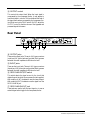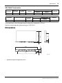
1
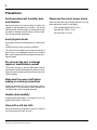
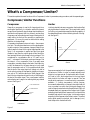
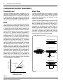
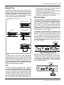
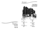
COMPRESSOR/LIMITER
GC2020C
Owner’s Manual
Mode d’emploi
Bedienungsanleitung
Manual del propietario
GAIN
REDUCTION
0
SIGNAL PEAK
EXP GATE THRESHOLD
RATIO
4
–4
GC2020C
COMP/LIMITER
0
10
0
10
0.3
10
1
1
00
RELEASE
5
20
–16
–24
3
2
–8
COMP
ATTACK
8
0.2
0.1
ms
CHANNEL A
20
0.05
sec
INPUT
GAIN
REDUCTION
0
–4
–8
OUTPUT
0.5
1
2
0
10
0
10
LINK
COMP
SIGNAL PEAK
EXP GATE THRESHOLD
ATTACK
8
3
0
10
0
10
0.3
00
0.2
0.1
ms
CHANNEL B
20
0.05
INPUT
POWER
OUTPUT
0.5
1
10
1
1
RELEASE
5
20
2
–16
–24
RATIO
4
sec
2
0
10
0
10
ON
OFF
i
Welcome to the GC2020C Compressor/Limiter
Introduction
Thank you for choosing the Yamaha GC2020C Compressor/Limiter. The GC2020C is a 2-channel high-performance
compressor/limiter designed for professional recording and
sound reinforcement applications. The GC2020C provides a
wide variety of control features for precise tailoring of compression and limiting parameters. It also features an
expander gate to eliminate source noise that can be accentuated by the compression process.
GC2020C compression can be used to add extra punch and
a more consistent level to a final mix, and channels can be
linked for stereo operation. A small amount of compression
provides a more consistent signal level when recording a
singer that tends to move closer to or further away from a
vocal microphone. Essentially, the compressor is reducing
Table of Contents
What’s a Compressor/Limiter? . . . . . . . . 1
Compressor/Limiter Functions . . . . . . 1
Compressor/Limiter Parameters . . . . . 2
Setting Up the Compressor/Limiter . . . 4
What’s an Expander/Gate? . . . . . . . . . . . 5
Setting Up the Expander/Gate . . . . . . 5
Controls & Connections . . . . . . . . . . . . . 6
Front Panel . . . . . . . . . . . . . . . . . . . . . 6
Rear Panel . . . . . . . . . . . . . . . . . . . . . . 7
Specifications . . . . . . . . . . . . . . . . . . . 8
Dimensions . . . . . . . . . . . . . . . . . . . . . 9
Block Diagram . . . . . . . . . . . . . . . . . 10
the dynamic range. This technique can also be used with
other instruments, such as acoustic guitar, bass guitar, and
piano. In fact, any instrument with a wide dynamic range can
be recorded more easily with a little compression applied.
Creative compressor application include adding extra punch
to bass, snare, and tom tom drums. GC2020C limiting can
be used to protect speakers in a sound reinforcement system.
Whether your applications are signal control, signal correction, or simply creative—the GC2020C is flexible enough to
handle all your needs.
To get the best from your GC2020C, read this manual thoroughly, and keep it in a safe place for future reference.
IMPORTANT NOTICE FOR
THE UNITED KINGDOM
Connecting the Plug and Cord
IMPORTANT: The wires in this mains lead are coloured in accordance
with the following code:
BLUE
: NEUTRAL
BROWN : LIVE
As the colours of the wires in the mains lead of this apparatus may not
correspond with the coloured markings identifying the terminals in your
plug proceed as follows:
The wire which is coloured BLUE must be connected to the terminal
which is marked with the letter N or coloured BLACK.
The wire which is coloured BROWN must be connected to the terminal
which is marked with the letter L or coloured RED.
Making sure that neither core is connected to the earth terminal of the
three pin plug.
* This applies only to products distributed by YAMAHA - KEMBLE
MUSIC (U.K.) LTD.
GC2020C Compressor/Limiter Owner’s Manual
ii
Precautions
Avoid excessive heat, humidity, dust,
and vibration
Keep the unit away from locations where it is likely to be
exposed to high temperatures or humidity—such as near
radiators, stoves, in direct sunlight, etc. Avoid locations that
are subject to excessive dust accumulation. Extreme vibrations can cause mechanical damage.
Avoid physical shocks
Strong physical shocks can damage the unit. Handle it with
care.
Install the unit with plenty of space for ventilation
This unit should be installed in such a way as to maintain a
gap of 10 cm or more between the rear of the unit and the
wall. This will prevent heat build-up inside the unit and possible fire hazard.
Do not open the unit, or attempt
repairs or modifications yourself
This product contains no user-serviceable parts. Prefer all
maintenance to qualified Yamaha service personnel. Opening the unit and/or tampering with the internal circuitry will
void the warranty.
Make sure the power is off before
making or removing connections
Always turn the power OFF prior to connecting or disconnecting cables. This is important to prevent damage to the
unit itself as well as other connected equipment.
Handle cables carefully
Always plug and unplug cables—including the AC cord—by
gripping the connector, not the cord.
Clean with a soft dry cloth
Never use solvents such as benzine or thinner to clean the
unit. Wipe it clean with a soft, dry cloth.
GC2020C Compressor/Limiter Owner’s Manual
Always use the correct power source
Make sure the power source voltage specified on the rear
panel matches your local AC mains supply:
US & Canadian Model: 120V AC, 60 Hz
General Model: 230V AC, 50 Hz
UK Model: 240V AC, 50 Hz
What’s a Compressor/Limiter?
1
What’s a Compressor/Limiter?
This section explains the main functions of the Compressor/Limiter. Its parameters, setup procedure, and the expander/gate.
Compressor/Limiter Functions
Compressor
Limiter
Generally, a compressor is used to fit a large signal into a
small space. Specifically, in a situation where the dynamic
range of the original audio signal is larger than the electronic
reproduction equipment that is to process it can handle, a
compressor can reduce the dynamic range of the signal to fit
neatly within the limits of the recording or reproduction
equipment. Of course, this must be done without adding
distortion to the signal itself.
Limiting is basically extreme compression that is set to affect
only signals above a certain level. This is particularly useful
for limiting only peaks that exceed the handling capacity of
the related equipment, without affecting the rest of the signal. See Figure 2.
1:1 NO COMPRESSION
Output Signal Level
(dB)
0
2:1 COMPRESSION
Threshold
Level
Input Signal Level
(dB)
Output Signal Level
Compression is expressed in terms of a ratio—the compression ratio. This ratio describes how much the signal appearing at the output of the compressor changes in relation to a
given change in the level of the original signal applied to the
input. If no compression is applied and the input signal
doubles in level, then the output signal will also double in
level, precisely following the change in the input signal. This
corresponds to a compression ratio of 1:1 (read “one to
one”) —a change of 1 at the input produces a change of 1 at
the output—i.e. no compression. Now if we apply some
compression, a smaller change in the level of the output signal will be observed for the same change in input signal
level. A compression ratio of 2:1, for example, would mean
that the level of the output signal will change only half as
much as the input signal. Expressed in decibels, a compression ratio of 20:1 would mean that a 20 dB change in the
level of the input signal would result in only a 1 dB change in
the level of the output signal. Thus, a compressor is able to
reduce the dynamic range of an audio signal by any desired
amount. See Figure 1.
(dB)
Limiting
Threshold
0
Input Signal Level
(dB)
LIMITING
Figure 2
Suppose we wanted to limit the peak levels in a program to
a maximum of 0 dBm, in order to prevent saturation and
distortion in a tape recorder. First we would set the “threshold” level to 0 dB—the threshold level is the input signal
level at which the limiter will begin to operate. Then we
would set the maximum (or near maximum) compression
available—∞:1 (infinity compression). Infinity compression means that absolutely no change in the output level will
occur no matter how much the input signal changes. As a
result, all signal content below the threshold level (0 dB) will
be passed exactly as it appears at the limiters input. Signals
exceeding the threshold level, however, will be output at the
threshold level and will rise no higher. In this case no signal
exceeding 0 dB will appear at the limiter’s output. The actual
audio signal remains untouched, just its average (r.m.s.)
level is kept within the defined limits.
COMPRESSION
Figure 1
GC2020C Compressor/Limiter Owner’s Manual
2
Compressor/Limiter Parameters
Compressor/Limiter Parameters
Threshold Level
Attack Time
Threshold is the signal level at which compression or limiting begins. All signals below the set threshold level are
passed as received at the INPUT jacks, with no compression
or limiting applied. Signals going above the set threshold
level, however, are compressed or limited according to the
settings of the RATIO, ATTACK, and RELEASE controls.
The Attack Time determines how long it takes—in milliseconds—before the full amount of compression is applied
once the threshold level is exceeded. The ATTACK time
range is from 0.2 milliseconds, a very fast attack, to a relatively slow 20 milliseconds.
Ratio
This is the amount of compression applied to signals that
exceed the threshold level set by the THRESHOLD control.
The compression ratio is expressed in terms of the amount
of change in the level of the input signal in relation to the
corresponding amount of change in the level of the output
signal. A high ratio means a lot of compression. A compression ratio of 1:1, therefore, implies no compression—a
change of 1 in the level of the input signal produces a corresponding change of 1 in the level of the output signal. A
compression ratio of 2:1, however, means that for a given
change in the level of the input signal (2) the level of the output signal will only change half as much (1). The extreme
would be a compression ratio of ∞:1 (infinity to one), meaning that no matter how much the input signal level changes
the output signal level will remain constant. The ∞:1 compression ratio is most commonly used in hard limiting
applications where the signal level must be prevented from
exceeding a specific value (frequently 0 dB). Extremely high
compression ratios in the range of 20:1 can add sustain to
instrument sounds—especially electric guitar and bass—as
well as creating a contemporary drum sound. Lower compression ratios—from less than 2:1 to 8:1—are useful for
making vocals sound smoother and minimizing the level
variations that occur when a speaker or singer moves closer
to or further away from a microphone.
The attack time setting depends largely on the type of signal
being processed and the type of effect desired. A very fast
attack, for example, will compress the initial attack of an
instrumental note making it sound “dull”. High levels of
compression are sometimes used on electric guitar, for
example, to give the sound greater sustain. In this application it is often better to set a longer attack time so that the
crisp attack of the guitar note “gets through” before full
compression is applied. Set the attack time to accommodate
the natural attack of the sound being processed.
ATTACK TIME Control Function
Attack Time set to zero
Input Signal
Fast Attack Time
Attack Time
+30
Output Signal Level (dB)
1:1
Slow Attack Time
+20
+10
0
Threshold level
2:1
–10
4:1
8:1
–20
20:1
:1
–30
Attack Time
–40
–50
–70
–60 –50 –40 –30 –20
–10
0
+10 +20
Intput Signal Level (dB)
COMPRESSION RATIOS
Figure 3
GC2020C Compressor/Limiter Owner’s Manual
+30
Figure 4
3
Compressor/Limiter Parameters
Release Time
The Release Time determines how long it takes for the compression to return to zero once the audio signal falls below
the threshold level. The RELEASE time range is from 50 milliseconds (0.05 seconds) to 2 seconds. Like the ATTACK
control, the RELEASE control setting depends on the type
of signal being processed and the desired effect.
RELEASE TIME Contorl Function
Release Time set to zero
Input Signal
Fast Release Time
Release Time
• The compressor/limiters use the Threshold Level setting
of the channel whose level setting is higher.
• The expander/noise gates use the Threshold Level setting
of the channel whose level setting is lower.
• For Attack Time and Release Time, the channel with the
faster (shorter) settings determines the settings.
External trigger
Compressor/limiters normally begin compression when
they detect that the input signal has exceeded the threshold
level. However, it is also possible to use a signal other than
the input signal as the trigger. The GC2020C provides a
SIDE CHAIN OUT jack that splits the input signal and
sends it to an external device, and a SIDE CHAIN IN jack
that lets a signal from an external device control the compressor/limiter. Using an external trigger allows more
sophisticated control of the GC2020C.
For example, if you connect the SIDE CHAIN OUT jack of
channel B to the SIDE CHAIN IN jack of channel A so that
channel A is controlled by an external trigger (i.e. channel
B), you can apply the compressor/limiter to the channel A
signal only when the channel B signal exceeds the threshold.
This is an easy way to produce the “ducking” effect that DJ's
or announcers use to automatically lower the volume of the
music when they speak.
INT EXT
Slow Release Time
CHANNEL A
OUTPUT
+4dB
SIDECHAIN
IN
INPUT
+4dB
SIDECHAIN
OUT
IN
KEY
INT EXT
OUT
KEY
INT EXT
Release Time
Figure 5
The main reason for this control is that if compression
stopped abruptly the instant the signal fell below threshold
level there would be a corresponding abrupt and unnatural
change in the level of the audio signal—particularly with
musical instruments that have a long, gentle decay slope.
Unless a particular effect is desired, set the RELEASE time to
accommodate the signal being processed.
Link
This function makes the compressor/limiter of channel A
and of channel B operate together. When a compressor/limiter is used to process a stereo signal, using two independent
channels of compression causes the stereo image to waver
unsteadily, producing an unnatural effect. If the two channels are linked, however, the same compression is applied to
both channels, preserving the stereo image. When Link is
ON, the parameters of both channels are linked as follows.
By connecting an equalizer between the SIDE CHAIN OUT
and SIDE CHAIN IN jacks, boosting the 3–5 kHz region,
and setting that channel to operate with an external trigger,
you can apply a de-esser effect, in which the compressor/limiter applies only to sibilant sounds (sounds with a
pronounced S component).
INT EXT
CHANNEL A
OUTPUT
+4dB
INPUT
+4dB
SIDECHAIN
IN
OUT
KEY
INT EXT
Equalizer
GC2020C Compressor/Limiter Owner’s Manual
4
Setting Up the Compressor/Limiter
Setting Up the Compressor/Limiter
1. Set the INPUT and OUTPUT controls midway.
2. Set the Threshold Level and Ratio as appropriate for
your application.
3. Adjust the OUTPUT control so that the PEAK indicator
just lights up at the loudest signals.
4. Set the Attack and Release times as appropriate.
GC2020C Compressor/Limiter Owner’s Manual
What’s an Expander/Gate?
5
What’s an Expander/Gate?
The GC2020C features a expander/gate that is independent
of the compressor/limiter. Expander/gate is a function that
effectively eliminates hum or noise that would otherwise be
heard during silent portions of the program. It works by
closing the gate to cut off the output signal when the input
signal falls below a specified level (the gate threshold level).
Normally you will set the gate level below the lowest level of
the musical portion, so that the gate will always be “open”
during the music to let the signal pass. Hum or noise that is
lower in level than the music will thus be effectively eliminated.
• EXP GATE Function
OUTPUT SIGNAL
INPUT SIGNAL
Music Signal
Level
Level
Music Signal
Noise
Noise
Time
Expander gate
threshold level
Signals in
this range
muted
Signals in
this range
muted
Signals in
this range
muted
Time
Setting Up the Expander/Gate
1. Adjust the input level so that the PEAK indicator just
lights up at the loudest signals.
2. Without playing the instrument, gradually raise the Gate
Threshold Level, and set it at a position slightly above the
point where noise is no longer audible.
3. Input a signal and check that its decay is not cut off
unnaturally for the most softly played notes. If the tail
end of the decay is cut off, lower the Gate Threshold
slightly.
GC2020C Compressor/Limiter Owner’s Manual
6
Controls & Connections
Controls & Connections
Front Panel
AB
GAIN
REDUCTION
0
SIGNAL PEAK
EXP GATE THRESHOLD
RATIO
4
–4
3
0
10
0
10
0.3
10
1
1
00
RELEASE
5
20
–16
–24
8
2
–8
COMP
ATTACK
0.2
0.1
ms
20
0.05
sec
INPUT
GAIN
REDUCTION
0
–4
–8
OUTPUT
0.5
1
2
0
10
0
LINK
10
COMP
RATIO
4
ATTACK
8
3
0
10
0
10
0.3
10
1
00
1
RELEASE
5
20
2
–16
–24
CHANNEL A
SIGNAL PEAK
EXP GATE THRESHOLD
0.2
0.1
ms
20
0.05
sec
INPUT
POWER
OUTPUT
0.5
1
2
0
10
0
10
CHANNEL B
2 3 4 5 6 7
8 9 0
ON
C
OFF
1
1 POWER Switch
6 THRESHOLD control
Press this switch to power up the GC2020C. The power indicator lights up. To power down the GC2020C, press this
switch again. The power indicator goes out.
This sets the level at which the compressor/limiter begins to
take effect.
2 LINK switch
This turns Link ON and OFF. When Link is ON, the LED
indicator lights up. Press the switch once again to turn it
OFF. When Link is ON, compression and limiting is applied
equally to both channels, so that a stereo signal can be processed correctly.
NOTE: When using Link, set the COMP switch on both
channels to ON. And set the INPUT control and COMP
RATIO control on both channels to the same values.
3 COMP switch & indicator
7 RATIO control
This determines the amount of compression that is applied
to signals that exceed the threshold level. The range is from 1
(1:1 ratio) to infinity (infinity:1 ratio).
8 ATTACK control
This determines the speed (in milliseconds) with which
compression begins after a signal exceeding the threshold is
detected. The range is from 0.2 msec (very fast attack time)
to 20 msec (relatively slow attack).
9 RELEASE control
This determines the speed at which compression is removed
after the signal falls below the threshold level. The range
from 50 msec to 2 sec.
This switch determines whether the compressor/limiter is
active, or bypassed. When this switch is ON, the LED indicator lights up, and the compressor/limiter circuit is active.
When it is OFF, the indicator is OFF, and the compressor/limiter circuit is completely bypassed, so the input signal
is sent straight to the output jack.
This controls the input level. A wide range of input signals
can be accommodated.
4 GAIN REDUCTION meter
A SIGNAL indicator
This five-segment LED meter shows the amount of gain
reduction that is being applied by the compressor/limiter.
The LEDs indicate 0 dB, –4 dB, –8 dB, –16 dB, and –24 dB of
gain reduction.
This indicator shows that a signal is present in the compressor/limiter. It lights up when the output signal is 13 dB
below the nominal level.
5 EXP GATE control & indicator
The EXP GATE control is used to set the threshold level of
the expander gate. When this control is turned hard left, the
gate function is OFF. The LED above the EXP GATE control
shows the operation of the expander gate, and light up when
the gate is closed.
GC2020C Compressor/Limiter Owner’s Manual
0 INPUT control
B PEAK indicator
This indicator shows that a signal is about to clip. It lights up
when the output signal is 3 dB below the clip point. Adjust
the OUTPUT control so that this indicator just lights up at
the loudest signals.
Rear Panel
7
C OUTPUT control
This controls the output level. When the input signal is
compressed by the compressor/limiter, it may appear to
have diminished in volume. This knob adjusts the level of
the signal that has been processed by the compressor/limiter. While turning the COMP switch ON/OFF, adjust the
OUTPUT control so that the volume of the bypassed and
processed signals is the same.
Rear Panel
CHANNEL B
OUTPUT
+4dB
CHANNEL A
INPUT
+4dB
OUTPUT
+4dB
SIDECHAIN
IN
KEY
INT EXT
D
E
F
INPUT
+4dB
SIDECHAIN
OUT
IN
OUT
KEY
INT EXT
G
D OUTPUT jacks
These are the output jacks. Three-pin XLR type connectors
(male) and 1/4" phone jacks are provided. Both types are
balanced. Nominal impedance is 600 ohms for both.
E INPUT jacks
These are the input jacks. Three-pin XLR type connectors
(female) and 1/4" phone jacks are provided. Both types are
balanced. Nominal impedance is 600 ohms for both.
F SIDE CHAIN INT/EXT switch
This switch selects the signal source for the circuit that
detects the point at which the compressor/limiter is applied.
With a setting of INT, the detector uses the channel signal.
With a setting of EXT, the detector uses the signal from the
SIDE CHAIN IN jack.
G SIDE CHAIN IN/OUT jack
These jacks are used to split the input signal, or to use an
external signal as the trigger for the compressor/limiter.
GC2020C Compressor/Limiter Owner’s Manual
8
Specifications
Specifications
Frequency Response
0+1
dB 20 Hz— 20 kHz @+4 dB
–3
Link
OFF/ON
Total Harmonic Distortion
Less than 0.05% (THD + N)
20 Hz — 20 kHz @+4 dB
Controls
(per CH.)
Input Level, Output Level,
Exp. Gate (with ON/OFF switch),
Comp. Ratio, Threshold Level,
Attack Time, Release Time,
Comp switch
Hum & Noise (Average,
Rs=600 Ω) (Measured with
BPF 20 Hz — 20 kHz)
–85 dB
Power
Consumption
20W
Power
Requirement
USA and Canada
120 V 60 Hz
GENERAL
230 V 50 Hz
1:1—∞:1
(Maximum limiting 32 dB)
Compression Ratio
Compressor/Limiter
Threshold Level
+20 dB — –35 dB
(Input Control at 0 : +20 dB — +5 dB)
(Input Control at 5 : +20 dB — –20 dB)
(Input Control at 10 : +5 dB — –35 dB)
Dimensions
(W×H×D)
480×49.4×246mm
Expander Noise Gate
Threshold
+0 dB — –80 dB
(Input Control at 0 : 0 dB — –40 dB)
(Input Control at 5 : –25 dB — –65 dB)
(Input Control at 10 : –40 dB — –80 dB)
Weight
3.2kg
Attack Time
0.2 ms — 20 ms
Release Time
50 ms — 2.0s
Gain Reduction
5 Segment LED Meter
Peak Indicators
Red LED on each channel lights up when
the output signal is 3 dB below clipping.
Signal Indicators
Green LED on each channel lights up
when the output signal is 17 dB below
the nominal level.
* Measurement conditions
Link switch ............................ OFF
Input Level ............................ 5 (center)
Output Level ......................... 5 (center)
Exp. Gate .............................. switch OFF
Comp. Ratio.......................... 1 : 1 (minimum)
Threshold Level ..................... 0 (minimum)
Attack Time........................... 0.2 ms (minimum)
Release Time ......................... 50 ms (minimum)
Key switch............................. INT
Input Characteristics
Connection
Actual Load
Impedance
For Use With Nominal
Sensitivity
INPUT
15 kΩ
600 Ω Lines
+4 dB (1.23 V)
Input level
Maximum Before
Nominal
Clipping
+4 dB (1.23 V)
+20 dB (7.75 V)
Connectors
XLR-3-31 Type
Phone Jack
Output Characteristics
Connection
Actual Source
Impedance
For Use With
Nominal
OUTPUT
150 Ω
600 Ω Lines
Output Level
Maximum Before
Nominal
Clipping
+4 dB (1.23 V)
+20 dB (7.75 V)
In these specifications, when dB represents a specific voltage, 0 dB is referenced to 0.775 Vrms.
XLR type connectors and phone jacks (TRS) are balanced. (T=HOT, R=COLD, S=GND)
Sensitivity is the level required to produce an output of +4 dB (1.23 V).
GC2020C Compressor/Limiter Owner’s Manual
Connectors
XLR-3-32 Type
Phone Jack
Specifications
9
SIDE CHAIN Characteristics
Connection
Actual Load
Impedance
For Use With
Nominal
Sensitivity
SIDE CHAIN IN
27 kΩ
600 Ω Lines
+4 dB (1.23 V)
Connection
Actual Source Impedance
For Use With
Nominal
SIDE CHAIN OUT
600 Ω
10 kΩ Lines
Input Level
Maximum Before
Nominal
Clipping
+4 dB (1.23 V)
+20 dB (7.75 V)
Output Level
Maximum Before
Nominal
Clipping
+4 dB (1.23 V)
+20 dB (7.75 V)
Connectors
phono
Connectors
phono
In these specifications, when dB represents a specific voltage, 0 dB is referenced to 0.775 Vrms.
Sensitivity is the level required to produce an output of +4 dB (1.23 V)
150
30
D:246
H:49.4
16
2
228
Dimensions
402
5.4
44
W:480
Unit : mm
• Specifications subject to change without notice.
GC2020C Compressor/Limiter Owner’s Manual
10
Block Diagram
Block Diagram
HA
CHANNEL A
VCA
INPUT +4dB
OUTPUT
COMP
INPUT
+4dB
OUTPUT
SIGNAL
CHANNEL A
PEAK
OUT
SIDECHAIN
IN
COMP
RATIO
ENVELOPE
GENERATOR
VOLTAGE
SHIFTER
0
THRESHOLD
-4
INT
ATTACK
-8
RATIO
RELEASE
-16
-24
(to CH B)
EXT
GAIN REDUCTION
LINK
KEY
f(x)=1/x
EXP GATE
EXP GATE
EXP GATE
(to CH B)
CHANNEL B
HA
VCA
INPUT +4dB
OUTPUT
COMP
INPUT
SIGNAL
CHANNEL B
OUT
SIDECHAIN
IN
GC2020C Compressor/Limiter Owner’s Manual
+4dB
OUTPUT
PEAK
GC 2020C m R1 1 IP 52
Printed in China
YAMAHA CORPORATION
P.O. Box 1, Hamamatsu, Japan