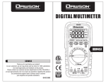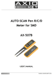
1
Technical Manual
SPLIT SYSTEM AIR CONDITIONER
A i r
C o n d i t i o n e r s
Super SKY
AUG.2000 5130-26135-87
CONTENTS
A . PREFACE
page
P-1
1 . Super SKY LINE GENERAL DESCRIPTION
1.1 Product Options
1.2 Name plate information
1.3 Technical data table
1.4 Standards compliance and agency license listings
1.5 Bar-code system
1-1
1-1
1-2
1-3
1-5
1-6
2 . WIRING & REFRIGERATION CYCLE DIAGRAMS, CAPACITY &
PRESSURE CHARTS
2.1 Using cooling and heating Capacity Curves
2.1.1 Cooling and Heating Capacity Curves AVL 25
2.1.2 Cooling and Heating Capacity Curves AVL 35
2.1.3 Cooling and Heating Capacity Curves AVL 50
2.1.4 Cooling and Heating Capacity Curves AVL 60
2.1.5 Cooling and Heating Capacity Curves AVL 603
2.1.6 Cooling and Heating Capacity Curves AVL 753
2.1.7 System Performance Charts AVL 25
2.1.8 System Performance Charts AVL 35
2.1.9 System Performance Charts AVL 50
2.1.10 System Performance Charts AVL 60
2.1.11 System Performance Charts AVL 603
2.1.12 System Performance Charts AVL 753
2-1
2-1
2-2
2-3
2-4
2-5
2-6
2-7
2-8
2-9
2-10
2-11
2-12
2-13
2.2 Refrigeration Cycle
2.2.1 Refrigeration Cycle AVL 25
2.2.2 Refrigeration Cycle AVL 35
2.2.3 Refrigeration Cycle AVL 353
2.2.4 Refrigeration Cycle AVL 50
2.2.5 Refrigeration Cycle AVL 503
2.2.6 Refrigeration Cycle AVL 60
2.2.7 Refrigeration Cycle AVL 603
2.2.8 Refrigeration Cycle AVL 753
2-14
2-14
2-15
2-16
2-17
2-18
2-19
2-20
2-21
2.3 AVL – Low Profile Ducted Mini Central Unit
2.3.1 Installation
2-22
2-22
2.4 Air flow Curves
2.4.1 Air flow Curves AVL 25 / 35 / 50 / 60
2.4.2 Air flow Curves AVL 753
2-26
2-26
2-27
2.5 Electrical & wiring Diagram
2.5.1 AVL 1 PH
2.5.2 AVL 3 PH
2-28
2-28
2-29
1--1 I
Super SKY
A . Preface
INTRODUCTION
The Service Manual for AVL model split air-conditioners provides comprehensive technical
documentation for the equipment.
This manual contains information intended for a variety of uses and is intended for
application engineers, architects, designers and various level service and installation
personnel.
This manual includes information on the optional features offered by the AVL series. In
addition, it includes general information for service personnel on split air-conditioners,
electrical wiring diagrams, refrigeration cycle diagrams and cooling & heating capacity
curves for the various series models.
AUG.2000 5130-26135-87
Created by:
Alex LIBERMAN
Technical Support
International Marketing
[email protected]
Tadiran reserves the right to change product specifications without prior notice.
1-0P-1
Super SKY
1 . Super SKY LINE GENERAL DESCRIPTION
1 . 1 Product Options
Line: AVL
Characteristics: Low Profile Mini-Central
50Hz Models:
Options
1 PHASE
3 PHASE
50Hz Models
AVL 25
AVL 35
AVL 50
AVL 60
AVL 353
AVL 503
AVL 603
AVL 753
C
✔
✔
✔
✔
✔
✔
✔
✔
C
- Cooling only (No heat pump).
H
- Heating and Cooling by heat pump.
H
✔
✔
✔
✔
✔
✔
✔
✔
AUG.2000 5130-26135-87
- Non Exist
✔
1-11-1
- Exist
Super SKY
1 . 2 Nameplate Information
Technical information for a specific unit appears on the unit nameplate,
which is attached to the indoor and/or the outdoor units.
(See Figure 1-1: Typical Technical Data Nameplate for 50Hz models).
The 50Hz models Nameplate includes the following information:
MODEL
Air-conditioner (A/C) model name.
CLIMATE CLASS
Type of climate for which the unit was designated - classified by:
Class A (standard) or Class B (desert conditions < 52°C.)
VOLT/PHASE/Hz
A/C power supply, for example: 230/1/50 = 230V/1ph/50Hz.
COS (j)
Power factor for the unit.
FUSE
Required fuse size (Amp.)
CAPACITORS [mF]
All capacitor values according to this sequence (Compressor
capacitor / Outdoor motor capacitor / Indoor motor capacitor).
REFRIGERANT R-22 [gr]
Quantity of refrigerant charge (for 8 m piping length).
COMPRESSOR
Type and Catalogue No. of compressor.
CAPACITY BTU/H
Cooling and Heating capacity in Btu/h according to ISO 5151
standard (1000Btu/h=293W).
CAPACITY W
Cooling and Heating capacity in Watts (1000W=3,413Btu/h).
INPUT POWER
Power consumption in cooling and heating modes (Watts).
AMPER
Current consumption in cooling and heating modes (Amp.).
SERIAL NO.
Unit serial number (normally blank, since Bar Code system is
AUG.2000 5130-26135-87
used).
Figure 1-1: Typical Technical Data Nameplate for 50Hz Units (Sample).
1-21-2
Super SKY
1 . 3 Technical data table
Specifications for AVL 50Hz Models
Model
50Hz
AVL-25
Cooling Capacity
Btu/h
Kcal/h
(Watt)
Btu/h
Kcal/h
(Watt)
Watt
Watt
Amp. - 1ph
- 3ph
Cool
Heat
l/h
Volt/Hz/ph
j
f - mm (in)
f - in
mm (in)
m (ft.)
m (ft.)
Amp.
24,000
6,060
(7,030)
28,000
7,070
(8,210)
2,670
2,650
12.5 / 12.4
Heating Capacity
Power Consumption Cooling
Power Consumption Heating
Operating Current
(Cooling/Heating)
EER – Energy Efficiency Ratio
COP – Coefficient Of Performance
Moisture Removal
Power Supply
Power Factor
Refrigerant Lines - Drain
Liquid/Gas Lines
Minimal insulation thickness
Maximum Piping Length
Maximum Height Difference *
Time Delay Fuse - 1ph-h
- 3ph-h
Control Mode
Temperature Control
A/C Options:
Indoor Unit
50Hz
Front Panel
Air Filter
Air Direction Control
Dimensions (LxHxD)
Color
OCT. 2000 5130-26135-87
Air Flow
(Turbo/High/Low)
Noise Level (Turbo/High/Low)
Net Static Pressure H2O
Net Weight
Indoor Fan Motor:
Speed (Turbo/High/Low)
Full Load Amperage
Capacitor
Electrical Heater
Blower Wheel
mm
in
3
m /h
cfm
dBA
mm (in)
Kg (Lb.)
HP
R.P.M.
Amp.
mF/Volt
Watt
Type
Outdoor Unit
50Hz
Casing
Dimensions (LxHxD)
Color
mm
in
3
m /h
cfm
dBA
Kg. (Lb.)
Type
AVL-35 / 353
AVL-25
45 (99)
AVL-25
AVL-35 / 353
AVL-50 / 503
Metallic
Removable/Washable 2 Filters
Air Ducts
1150 ¥ 285 ¥ 750
45 1/4¥ 11 7/32 ¥ 29 1/2
2040 / 1785 / 1445
1200 / 1050 / 850
37 / 32 / 29
7.5 (0.3)
47 (103)
1/5
930 / 800 / 650
1.2
5mF / 400V
Under Development
2 Centrifugal Blowers
AVL-35 / 353
38 / 36 / 34
AVL-50 / 503
White
900 ¥ 640 ¥ 320
35 7/16¥ 25 3/16 ¥ 12 19/32
Air Flow (High/Medium/Low)
3,910 / 3,060 / 2,210
2,300 / 1,800 / 1,300
Noise Level (High/Medium/Low)
53 / 50 / 48
Net Weight
65 (143)
65 (143)
Fittings
Flare
Compressor - 1ph
H29B32UABKA
H29B35UABKA
- 3ph
H25B353DBEA
Thermal Protector
Overload
Full Load Amperage - 1ph
Amp.
12.4
12.4
- 3ph
3 ¥ 4.7
Lock Rotor Amperage - 1ph
Amp.
76.0
76.0
- 3ph
3 ¥ 42.0
Compressor Capacitor
mF/Volt
40mF / 400V
40mF / 400V
Capillary
1ph
2 ¥ 0.064" ¥ 32"
2 ¥ 0.070" ¥ 38"
3ph
2 ¥ 0.070" ¥ 38"
R-22 Freon Gas - 1ph
gr. (Oz.)
2,120 (74.8)
1,970 (69.5)
- 3ph
1,970 (69.5)
Oil for Compressor
Type
3GS or compatible
Outdoor Fan Motor:
HP
1/5
Capacitor
mF/Volt
5mF / 400V
Speed (High/Medium/Low)
R.P.M.
900 / 700 / 500
Motor Full Load Amperage
Amp.
1.3
Specifications and performance data are subject to change without notice.
E.C. 1003
AVL-50 / 503
28,000
33,000
7,070
8,330
(8,210)
(9,670)
31,000
36,000
7,830
9,090
(9,090)
(10,550)
3,110
3,670
2,930
3,400
14.3 / 13.7
17.1 / 15.9
7.8,4.8,4.8 / 7.7,4.7,4.7
8.5,5.5,5.5 / 8.3,5.3,5.3
9.0
9.0
9.0
3.1
3.1
3.1
3.1
3.8
4.2
220/240V, 50Hz, 1ph
220/240V, 50Hz, 1ph or 380/415V, 50Hz, 3ph
0.93
0.94
0.93
16 (5/8)
3/8 ; 5/8 (insulated)
7 (9/32)
30 (98’)
15 (49’)
20
20
25
3 ¥ 10
3 ¥ 10
I.R. Remote Control / Auto
Microcomputer
C (Cool only) / H (Heat pump) / HDE (H + Heating Element) - under development
1-31-3
1100 ¥ 640 ¥ 320
43 5/16¥ 25 3/16¥ 12 19/32
73 (160)
H28A423ABKA
H23A423DBEA
16.8
3 ¥ 5.8
92.0
3 ¥ 39.0
60mF / 400V
2 ¥ 0.070" ¥ 32"
2 ¥ 0.070" ¥ 32"
2,030 (71.6)
2,030 (71.6)
Super SKY
Specifications for AVL 50Hz Models Continued
Model
50Hz
AVL-60
AVL-603
AVL-75
Cooling Capacity
Btu/h
Kcal/h
(Watt)
Btu/h
Kcal/h
(Watt)
Watt
Watt
Amp. - 1ph
- 3ph
Cool
Heat
36,000
9,090
(10,550)
37,000
9,340
(10,850)
3,700
3,500
17.5 / 16.5
38,000
9,600
(11,140)
40,000
10,100
(11,720)
3,920
3,780
43,500
10,980
(12,750)
51,000
12,880
(14,950)
5,000
4,400
9.0,6.0,6.0 / 8.7,5.7,5.7
9.7
3.1
11.0,7.0,7.0 / 10.0,6.0,6.0
8.7
3.4
l/h
Volt/Hz/ph
j
f - mm (in)
f - in
mm (in)
m (ft.)
m (ft.)
Amp.
4.7
220/240V, 50Hz, 1ph
0.92
4.7
5.2
Heating Capacity
Power Consumption Cooling
Power Consumption Heating
Operating Current
(Cooling/Heating)
EER – Energy Efficiency Ratio
COP – Coefficient Of
Performance
Moisture Removal
Power Supply
Power Factor
Refrigerant Lines - Drain
Liquid/Gas Lines
Minimal insulation thickness
Maximum Piping Length
Maximum Height Difference *
Time Delay Fuse - 1ph-h
- 3ph-h
Control Mode
Temperature Control
A/C Options:
Indoor Unit
50Hz
Front Panel
Air Filter
Air Direction Control
Dimensions (LxHxD)
Color
OCT. 2000 5130-26135-87
Air Flow
(Turbo/High/Low)
Noise Level
(Turbo/High/Low)
Net Static Pressure H2O
Net Weight
Indoor Fan Motor:
Speed (Turbo/High/Low)
Full Load Amperage
Capacitor
Electrical Heater
Blower Wheel
9.7
3.1
50Hz
Color
mm
in
m3/h
cfm
dBA
Kg. (Lb.)
Type
25
3 ¥ 12
3 ¥ 16
I.R. Remote Control / Auto
Microcomputer
C (Cool only) / H (Heat pump) / HDE (H + Heating Element) - under development
AVL-60
AVL-603
Metallic
Removable/Washable 2 Filters
Air Ducts
1150 ¥ 285 ¥ 750
45 1/4¥ 11 7/32 ¥ 29 1/2
2040 / 1785 / 1445
1200 / 1050 / 850
37 / 32 / 29
7.5 (0.3)
47 (103)
1/5
930 / 800 / 650
1.2
5mF / 400V
Under Development
2 Centrifugal Blowers
AVL-60
AVL-603
AVL-75
2550 / 2210 / 1870
1500 / 1300 / 1100
37 / 36 / 34
10.0 (0.4)
49 (108)
1/3
1100 / 950 / 800
2.4
15mF / 400V
AVL-75
White
1100 ¥ 640 ¥ 320
43 5/16 ¥ 25 3/16 ¥ 12 19/32
Air Flow (High/Medium/Low)
3,910 / 3,060 / 2,210
2,300 / 1,800 / 1,300
Noise Level (High/Medium/Low)
53 / 50 / 48
Net Weight
75 (165)
82 (180)
Fittings
Flare
Compressor - 1ph
H28A423ABKA
- 3ph
H23A50QDBEA
Thermal Protector
Overload
Full Load Amperage - 1ph
Amp.
16.8
- 3ph
3 ¥ 6.6
Lock Rotor Amperage - 1ph
Amp.
92.0
- 3ph
3 ¥ 53.0
Compressor Capacitor
mF/Volt
60mF / 400V
None
Capillary
1ph
2 ¥ 0.080" ¥ 55"
&
3ph
1 ¥ 0.054" ¥ 12" (1ph)
2 ¥ 0.080" ¥ 45"
R-22 Freon Gas - 1ph
gr. (Oz.)
2,700 (95.2)
- 3ph
2,550 (90.0)
Oil for Compressor
Type
3GS or compatible
Outdoor Fan Motor:
HP
1/5
Capacitor
mF/Volt
5mF / 400V
Speed (High/Medium/Low)
R.P.M.
900 / 700 / 500
Motor Full Load Amperage
Amp.
1.3
Specifications and performance data are subject to change without notice.
E.C. 1004
0.92
16 (5/8)
3/8 ; 3/4 (insulated)
7 (9/32)
30 (98’) *
15 (49’) *
mm (in)
Kg (Lb.)
HP
R.P.M.
Amp.
mF/Volt
Watt
Type
Casing
Dimensions (LxHxD)
0.92
16 (5/8)
3/8 ; 5/8 (insulated)
7 (9/32)
mm
in
m3/h
cfm
dBA
Outdoor Unit
380/415V, 50Hz, 3ph
1-41-4
1140 ¥ 640 ¥ 400
44 7/8 ¥ 25 3/16 ¥ 15 3/4
54 / 51 / 47
90 (198)
H23A56QDBEA
3 ¥ 7.5
3 ¥ 62.0
None
Expansion Valve
3,800 (134.0)
Super SKY
1 . 4 Standards Compliance and Agency License Listings
✔
- Approved
-
- Not Applicable (N/A)
50 Hz
Model
CE
GS(TUV)
AVL 25
AVL 35
AVL 50
AVL 60
AVL 353
AVL 503
AVL 603
AVL 753
✔
✔
✔
✔
✔
✔
✔
✔
✔
✔
✔
✔
✔
✔
✔
✔
T he
s Insti tuti on
da rd
of
ISO 9001
..
geprufte
Sicherheit
ua
l it
rm
..
TUV Rheinland
SI
el
Is ra
St
an
Q
AUG.2000 5130-26135-87
CE - Confirmation according to CE directives.
GS - Geprüfte Sicherheit (safety approved - German law)
ISO - International Standards Organization
i
y As su re d F
1-51-5
Super SKY
1 . 5 Bar-code system
Finished goods (packed evaporator or condenser) are labeled by Bar Code for easy
identification of product configuration and storage.
Each unit has Bar Code labels as shown below, one on each side of the packed unit
and small labels (with unit serial number only) are located on each unit (near the
nameplate on the evaporator, beneath the valves and in the connection box of the
condenser).
The structure of the Bar Code label:
A. Complete unit name, for example: GFL-2020C (GFL-2020 model without heat
pump).
B. Important components (up to 2 lines) about the specific unit, for example:
CARRIER MEXICO, NEW R.C, TAC-404.
C. Unit catalog number/order number, for example: CATALOG NO.
51382057712/880472 (prefix of 5138 for evaporator and 5139 for
condenser).
D. Unit serial number, for example: S/N 2248119059 = 22 - for factory use;
48 - 1998; 059185 - running (serial) number.
E. Tadiran order number, for example: 880472 = 88 - 1998; 0 group; 472 order running number.
F . Small S/N cables (X3).
An additional Bar Code label displays the PALLET NO. (see next page) and is used
for storage only.
A
B
AUG.2000 5130-26135-87
C
D
E
F
Figure 1-4: Typical Evaporator/Condenser Unit Bar Code Identification Label
1-61-6
Super SKY
AUG.2000 5130-26135-87
Figure 1-5: Typical Pallet Bar Code Label
1-71-7
Super SKY
2.
WIRING & REFRIGERATION CYCLE DIAGRAMS, CAPACITY &
PRESSURE CHARTS
2 . 1 Using AVL Model Air-Conditioner Cooling and Heating
Capacity Curves
Using the Cooling and Heating Capacity Curves.
The Cooling and Heating Characteristics curves are mainly intented for use by air
conditioning engineers as an aid in designing systems and in determining the
capacity and number of units required at a given site.
AUG.2000 5130-26135-87
The air conditioner capacities were determined in accordance with ISO 5151 standard
operating conditions:
Design parameters for a given site are often different than the standard
conditions. Therefore, the design engineer should use the capacity charts which
follow to calculate the capacity of the air conditioners under the intended
working conditions, in order to optimize the selection of air conditioner units for
use at a particular site.
1-82-1
Super SKY
2.1.1
Cooling and Heating Capacity Curves AVL 25
COOLING CAPACITY
OUTDOOR TEMP. [°F]
75.2
82.4
24
28
89.6
96.8
104
111.2
32
36
40
44
27000
CAPACITY [Btu/H]
26000
25000
24000
23000
22000
21000
OUTDOOR TEMP. [°C]
[Btu/H]
HEATING CAPACITY
OUTDOOR TEMP. [°F]
5
14
23
32
41
50
59
-15
-10
-5
0
5
10
15
40000
35000
CAPACITY [Btu/H]
30000
25000
20000
15000
10000
AUG.2000 5130-26135-87
5000
0
OUTDOOR TEMP. [°C]
[Btu/H]
COOLING
* OUTDOOR R.H. =
40%
INDOOR R.H. =
47%
INDOOR TEMP. =
27 °C
TURBO
MAX. AIR SPEED:
1-92-2
HEATING
* OUTDOOR R.H. =
77%
INDOOR TEMP. =
20 °C
AIR SPEED:
TURBO
Super SKY
2.1.2
Cooling and Heating Capacity Curves AVL 35
COOLING CAPACITY
OUTDOOR TEMP. [°F]
75.2
82.4
89.6
96.8
104
111.2
24
28
32
36
40
44
30500
30000
CAPACITY [Btu/H]
29500
29000
28500
28000
27500
27000
26500
26000
OUTDOOR TEMP. [°C]
[Btu/H]
HEATING CAPACITY
OUTDOOR TEMP. [°F]
5
14
23
32
41
50
59
-15
-10
-5
0
5
10
15
45000
40000
CAPACITY [Btu/H]
35000
30000
25000
AUG.2000 5130-26135-87
20000
15000
OUTDOOR TEMP. [°C]
[Btu/H]
COOLING
* OUTDOOR R.H. =
40%
INDOOR R.H. =
47%
INDOOR TEMP. =
27 °C
TURBO
MAX. AIR SPEED:
1-102-3
HEATING
* OUTDOOR R.H. =
77%
INDOOR TEMP. =
20 °C
AIR SPEED:
TURBO
Super SKY
2.1.3
Cooling and Heating Capacity Curves AVL 50
COOLING CAPACITY
OUTDOOR TEMP. [°F]
75.2
82.4
89.6
96.8
104
111.2
32
36
40
44
40000
35000
CAPACITY [Btu/H]
30000
25000
20000
15000
10000
5000
0
24
28
OUTDOOR TEMP. [°C]
[Btu/H]
HEATING CAPACITY
OUTDOOR TEMP. [°F]
5
14
23
32
41
50
59
-15
-10
-5
0
5
10
15
45000
40000
CAPACITY [Btu/H]
35000
30000
25000
20000
15000
AUG.2000 5130-26135-87
10000
5000
0
OUTDOOR TEMP. [°C]
[Btu/H]
COOLING
* OUTDOOR R.H. =
40%
INDOOR R.H. =
47%
INDOOR TEMP. =
27 °C
TURBO
MAX. AIR SPEED:
1-112-4
HEATING
* OUTDOOR R.H. =
77%
INDOOR TEMP. =
20 °C
AIR SPEED:
TURBO
Super SKY
2.1.4
Cooling and Heating Capacity Curves AVL 60
COOLING CAPACITY
OUTDOOR TEMP. [°F]
75.2
82.4
24
28
89.6
96.8
104
111.2
32
36
40
44
55000
50000
CAPACITY [Btu/H]
45000
40000
35000
30000
25000
20000
15000
10000
OUTDOOR TEMP. [°C]
[Btu/H]
HEATING CAPACITY
OUTDOOR TEMP [°F]
5
14
-15
-10
23
32
41
50
59
-5
0
5
10
15
55000
50000
CAPACITY [Btu/H]
45000
40000
35000
30000
25000
AUG.2000 5130-26135-87
20000
15000
10000
OUTDOOR TEMP [_C]
[Btu/H]
* OUTDOOR R.H. =
INDOOR R.H. =
INDOOR TEMP. =
MAX. AIR SPEED:
40%
47%
27 °C
TURBO
1-122-5
* OUTDOOR R.H. =
INDOOR TEMP. =
AIR SPEED:
77%
20 °C
TURBO
Super SKY
2.1.5
Cooling and Heating Capacity Curves AVL 603
COOLING CAPACITY
OUTDOOR TEMP. [°F]
75.2
82.4
24
28
89.6
96.8
104
111.2
32
36
40
44
39000
CAPACITY [Btu/H]
38500
38000
37500
37000
36500
36000
35500
35000
OUTDOOR TEMP. [°C]
[Btu/H]
HEATING CAPACITY
OUTDOOR TEMP [°F]
5
14
23
32
41
50
59
-5
0
5
10
15
50000
45000
CAPACITY [Btu/H]
40000
35000
30000
25000
20000
15000
AUG.2000 5130-26135-87
10000
5000
0
-15
-10
OUTDOOR TEMP [_C]
[Btu/H]
* OUTDOOR R.H. =
INDOOR R.H. =
INDOOR TEMP. =
MAX. AIR SPEED:
40%
47%
27 °C
TURBO
1-132-6
* OUTDOOR R.H. =
INDOOR TEMP. =
AIR SPEED:
77%
20 °C
TURBO
Super SKY
2.1.6
Cooling and Heating Capacity Curves AVL 753
COOLING CAPACITY
OUTDOOR TEMP. [°F]
75.2
82.4
24
28
89.6
96.8
104
111.2
32
36
40
44
48000
47000
46000
CAPACITY [Btu/H]
45000
44000
43000
42000
41000
40000
39000
38000
37000
OUTDOOR TEMP. [°C]
[Btu/H]
HEATING CAPACITY
OUTDOOR TEMP. [°F]
5
14
23
-15
-10
-5
32
41
50
59
0
5
10
15
70000
60000
CAPACITY [Btu/H]
50000
40000
30000
20000
AUG.2000 5130-26135-87
10000
0
OUTDOOR TEMP. [°C]
[Btu/H]
COOLING
* OUTDOOR R.H. =
40%
INDOOR R.H. =
47%
INDOOR TEMP. =
27 °C
TURBO
MAX. AIR SPEED:
1-142-7
HEATING
* OUTDOOR R.H. =
77%
INDOOR TEMP. =
20 °C
AIR SPEED:
TURBO
Super SKY
2.1.7
System Performance Charts AVL 25
HEATING DISCHARGE PRESSURE
COOLING DISCHARGE PRESSURE
350
350
300
PRESSURE [psi]
PRESSURE [psi]
300
250
200
150
100
50
250
200
150
100
50
0
0
24
28
32
36
40
44
-10
0
5
10
15
OUTDOOR TEMP. [°C]
COOLING SUCTION PRESSURE
HEATING SUCTION PRESSURE
70
80
70
68
60
PRESSURE [psi]
PRESSURE [psi]
-5
OUTDOOR TEMP. [°C]
66
64
62
50
40
30
20
60
10
58
0
24
28
32
36
40
-10
44
-5
0
5
10
15
OUTDOOR TEMP. [°C]
OUTDOOR TEMP. [°C]
COOLING INDOOR AIR dT
HEATING INDOOR AIR dT
8.5
16
14
12
dT [°C]
dT [°C]
8
7.5
7
10
8
6
4
6.5
AUG.2000 5130-26135-87
2
6
0
24
28
32
36
40
OUTDOOR TEMP. [°C]
COOLING
* OUTDOOR R.H. =
40%
INDOOR R.H. =
47%
INDOOR TEMP. =
27 °C
TURBO
MAX. AIR SPEED:
1-152-8
44
-10
-5
0
5
10
OUTDOOR TEMP. [°C]
HEATING
* OUTDOOR R.H. =
77%
INDOOR TEMP. =
20 °C
AIR SPEED:
TURBO
15
Super SKY
2.1.8
System Performance Charts AVL 35
HEATING DISCHARGE PRESSURE
COOLING DISCHARGE PRESSURE
400
300
250
300
PRESSURE [psi]
PRESSURE [psi]
350
250
200
150
100
200
150
100
50
50
0
0
24
28
32
36
40
44
-10
OUTDOOR TEMP. [°C]
-5
0
5
10
15
OUTDOOR TEMP. [°C]
COOLING SUCTION PRESSURE
HEATING SUCTION PRESSURE
90
80
70
85
PRESSURE [psi]
PRESSURE [psi]
60
80
75
70
50
40
30
20
10
0
65
24
28
32
36
40
-10
44
dT [°C]
dT [°C]
AUG.2000 5130-26135-87
28
32
36
40
COOLING
* OUTDOOR R.H. =
40%
INDOOR R.H. =
47%
INDOOR TEMP. =
27 °C
TURBO
MAX. AIR SPEED:
1-162-9
5
10
15
HEATING INDOOR AIR dT
COOLING INDOOR AIR dT
9.1
9
8.9
8.8
8.7
8.6
8.5
8.4
8.3
8.2
OUTDOOR TEMP. [°C]
0
OUTDOOR TEMP. [°C]
OUTDOOR TEMP. [°C]
24
-5
44
18
16
14
12
10
8
6
4
2
0
-10
-5
0
5
10
OUTDOOR TEMP. [°C]
HEATING
* OUTDOOR R.H. =
77%
INDOOR TEMP. =
20 °C
AIR SPEED:
TURBO
15
Super SKY
2.1.9
System Performance Charts AVL 50
HEATING DISCHARGE PRESSURE
350
350
300
300
250
PRESSURE [psi]
PRESSURE [psi]
COOLING DISCHARGE PRESSURE
200
150
100
50
250
200
150
100
50
0
0
24
28
32
36
40
44
-10
-5
0
5
10
15
OUTDOOR TEMP. [°C]
OUTDOOR TEMP. [°C]
COOLING SUCTION PRESSURE
HEATING SUCTION PRESSURE
70
70
68
60
50
64
PRESSURE [psi]
PRESSURE [psi]
66
62
60
58
56
54
40
30
20
10
0
52
24
28
32
36
40
-10
44
AUG.2000 5130-26135-87
32
36
40
OUTDOOR TEMP. [°C]
COOLING
* OUTDOOR R.H. =
40%
INDOOR R.H. =
47%
INDOOR TEMP. =
27 °C
TURBO
MAX. AIR SPEED:
1-17
2-10
5
10
15
HEATING INDOOR AIR dT
dT [°C]
dT [°C]
COOLING INDOOR AIR dT
11.6
11.4
11.2
11
10.8
10.6
10.4
10.2
10
9.8
9.6
28
0
OUTDOOR TEMP. [°C]
OUTDOOR TEMP. [°C]
24
-5
44
20
18
16
14
12
10
8
6
4
2
0
-10
-5
0
5
10
OUTDOOR TEMP. [°C]
HEATING
* OUTDOOR R.H. =
77%
INDOOR TEMP. =
20 °C
AIR SPEED:
TURBO
15
Super SKY
2.1.10
System Performance Charts AVL 60
COOLING DISCHARGE PRESSURE
HEATING DISCHARGE PRESSURE
400
350
350
300
PRESSURE [psi]
PRESSURE [psi]
300
250
200
150
100
50
250
200
150
100
50
0
0
24
28
32
36
40
-10
44
OUTDOOR TEMP. [°C]
-5
0
5
10
15
OUTDOOR TEMP. [°C]
COOLING SUCTION PRESSURE
HEATING SUCTION PRESSURE
90
80
85
70
PRESSURE [psi]
PRESSURE [psi]
60
80
75
70
65
50
40
30
20
10
0
60
24
28
32
36
40
-10
44
0
5
10
15
OUTDOOR TEMP. [°C]
OUTDOOR TEMP. [°C]
COOLING INDOOR AIR dT
12.6
-5
HEATING INDOOR AIR dT
25
12.5
20
12.4
dT [°C]
dT [°C]
12.3
12.2
12.1
15
10
12
5
AUG.2000 5130-26135-87
11.9
11.8
0
11.7
-10
24
28
32
36
40
OUTDOOR TEMP. [°C]
COOLING
* OUTDOOR R.H. =
40%
INDOOR R.H. =
47%
INDOOR TEMP. =
27 °C
TURBO
MAX. AIR SPEED:
1-18
2-11
44
-5
0
5
10
OUTDOOR TEMP. [°C]
HEATING
* OUTDOOR R.H. =
77%
INDOOR TEMP. =
20 °C
AIR SPEED:
TURBO
15
Super SKY
2.1.11
System Performance Charts AVL 603
HEATING DISCHARGE PRESSURE
400
350
350
300
300
250
PRESSURE [psi]
PRESSURE [psi]
COOLING DISCHARGE PRESSURE
250
200
150
100
50
200
150
100
50
0
0
24
28
32
36
40
-10
44
-5
0
5
10
15
OUTDOOR TEMP. [°C]
OUTDOOR TEMP. [°C]
HEATING SUCTION PRESSURE
COOLING SUCTION PRESSURE
90
80
85
70
PRESSURE [psi]
60
PRESSURE [psi]
80
50
75
40
30
70
20
65
10
0
60
24
28
32
36
40
-10
44
12.5
12.4
dT [°C]
dT [°C]
12.3
12.2
12.1
12
AUG.2000 5130-26135-87
11.9
11.8
11.7
28
32
36
40
OUTDOOR TEMP. [°C]
COOLING
* OUTDOOR R.H. =
40%
INDOOR R.H. =
47%
INDOOR TEMP. =
27 °C
TURBO
MAX. AIR SPEED:
2-12
1-19
0
5
10
15
HEATING INDOOR AIR dT
COOLING INDOOR AIR dT
12.6
24
-5
OUTDOOR TEMP. [°C]
OUTDOOR TEMP. [°C]
44
20
18
16
14
12
10
8
6
4
2
0
-10
-5
0
5
10
OUTDOOR TEMP. [°C]
HEATING
* OUTDOOR R.H. =
77%
INDOOR TEMP. =
20 °C
AIR SPEED:
TURBO
15
Super SKY
2.1.12
System Performance Charts AVL 753
COOLING DISCHARGE PRESSURE
HEATING DISCHARGE PRESSURE
400
400
350
300
PRESSURE [psi]
PRESSURE [psi]
350
250
200
150
100
50
300
250
200
150
100
50
0
0
24
28
32
36
40
44
48
-10
OUTDOOR TEMP. [°C]
COOLING SUCTION PRESSURE
0
5
10
15
HEATING SUCTION PRESSURE
71
80
70.5
70
70
60
69.5
PRESSURE [psi]
PRESSURE [psi]
-5
OUTDOOR TEMP. [°C]
69
68.5
68
67.5
50
40
30
20
10
67
0
66.5
24
28
32
36
40
44
-10
48
OUTDOOR TEMP. [°C]
-5
0
5
10
15
OUTDOOR TEMP. [°C]
COOLING INDOOR AIR dT
HEATING INDOOR AIR dT
12.5
25
12
20
dT [°C]
dT [°C]
11.5
11
10.5
15
10
AUG.2000 5130-26135-87
10
5
9.5
9
0
24
28
32
36
40
44
OUTDOOR TEMP. [°C]
COOLING
* OUTDOOR R.H. =
40%
INDOOR R.H. =
47%
INDOOR TEMP. =
27 °C
TURBO
MAX. AIR SPEED:
1-20
2-13
48
-10
-5
0
5
10
OUTDOOR TEMP. [°C]
HEATING
* OUTDOOR R.H. =
77%
INDOOR TEMP. =
20 °C
AIR SPEED:
TURBO
15
Super SKY
2 . 2 REFRIGERATION CYCLE
2.2.1
Refrigeration Cycle AVL 25
5/8"
D
V'
V
C
S
MUFFLER
RV
E
V
BRISTOL COMP.
H29B32UABKA
V'
V
27,500 BTU/HR
6,945 Kcal/HR
2570 WATTS
10.7 EER
V
AIR
MOTOR
1/5 HP
930/800/
650 RPM
IN
AIR
AIR
IN
OUT
WASHABLE
AIR
FILTER
MOTOR
1/5 HP
900/700/500 RPM
AIR
OUT
AIR
IN
BLOWERS
QTY:
2
DIAM. : 205 mm
WIDTH : 262 mm
BLADES : 66
PROPELLER
PLASTIC
6 BLADES
500 mm D.
L'
CAPILLARY
AUG.2000 5130-26135-87
L
L
3/8"
2 X 0.064" X 32"
OUTDOOR COIL
INDOOR COIL
2 ROWS
4 CIRCUITS
13 F.P.I.
48 PLAIN TUBES
E.C. 1005
1 ROWS
4 CIRCUITS
17 F.P.I.
16 GROOVED TUBES
1-21
2-14
Super SKY
2.2.2
Refrigeration Cycle AVL 35
5/8"
D
V'
V
C
S
MUFFLER
RV
E
BRISTOL COMP.
H29B35UABKA
V'
V
V
30,150 BTU/HR
7,615 Kcal/HR
2820 WATTS
10.7 EER
V
AIR
MOTOR
1/5 HP
530/800/
650 RPM
IN
AIR
AIR
IN
OUT
WASHABLE
AIR
FILTER
MOTOR
1/5 HP
900/700/500 RPM
AIR
OUT
AIR
IN
BLOWERS
QTY:
2
DIAM. : 205 mm
WIDTH : 262 mm
BLADES : 66
PROPELLER
PLASTIC
6 BLADES
500 mm D.
L'
CAPILLARY
AUG.2000 5130-26135-87
L
L
3/8"
2 X 0.070" X 38"
OUTDOOR COIL
INDOOR COIL
2 ROWS
4 CIRCUITS
13 F.P.I.
48 PLAIN TUBES
E.C. 1006
2 ROWS
4 CIRCUITS
17 F.P.I.
32 PLAIN TUBES
1-22
2-15
Super SKY
2.2.3
Refrigeration Cycle AVL 353
5/8"
D
V'
V
C
S
MUFFLER
RV
E
V
BRISTOL COMP.
H29B35UDBEA
V'
V
30,200 BTU/HR
7,630 Kcal/HR
2820 WATTS
10.7 EER
V
AIR
MOTOR
1/5 HP
930/820/
650 RPM
IN
AIR
AIR
IN
OUT
WASHABLE
AIR
FILTER
MOTOR
1/5 HP
900/700/500 RPM
AIR
OUT
AIR
IN
BLOWERS
QTY:
2
DIAM. : 205 mm
WIDTH : 262 mm
BLADES : 66
PROPELLER
PLASTIC
6 BLADES
500 mm D.
L'
CAPILLARY
AUG.2000 5130-26135-87
L
L
3/8"
2 X 0.070" X 38"
OUTDOOR COIL
INDOOR COIL
2 ROWS
4 CIRCUITS
13 F.P.I.
48 PLAIN TUBES
E.C. 1007
2 ROWS
4 CIRCUITS
17 F.P.I.
32 PLAIN TUBES
1-23
2-16
Super SKY
2.2.4
Refrigeration Cycle AVL 50
5/8"
D
V'
V
C
S
MUFFLER
RV
E
V
BRISTOL COMP.
H28A423ABKA
V'
V
37,000 BTU/HR
9,345 Kcal/HR
3410 WATTS
10.85 EER
V
AIR
MOTOR
1/5 HP
930/800/
650 RPM
IN
AIR
AIR
IN
OUT
WASHABLE
AIR
FILTER
MOTOR
1/5 HP
900/700/500 RPM
AIR
OUT
AIR
IN
BLOWERS
QTY:
2
DIAM. : 205 mm
WIDTH : 262 mm
BLADES: 66
PROPELLER
PLASTIC
6 BLADES
500 mm D.
L'
CAPILLARY
AUG.2000 5130-26135-87
L
L
3/8"
2 X 0.070" X 32"
OUTDOOR COIL
INDOOR COIL
2 ROWS
4 CIRCUITS
16 F.P.I.
48 PLAIN TUBES
E.C. 1008
2 ROWS
4 CIRCUITS
17 F.P.I.
32 PLAIN TUBES
1-24
2-17
Super SKY
2.2.5
Refrigeration Cycle AVL 503
5/8"
D
V'
V
C
S
MUFFLER
RV
E
V
BRISTOL COMP.
H23A423DBEA
V'
V
35,200 BTU/HR
8,890 Kcal/HR
3430 WATTS
10.25 EER
V
AIR
MOTOR
1/5 HP
930/800/
650 RPM
IN
AIR
AIR
IN
OUT
WASHABLE
AIR
FILTER
MOTOR
1/5 HP
900/700/500 RPM
AIR
OUT
AIR
IN
BLOWERS
QTY:
2
DIAM. : 205 mm
WIDTH : 262 mm
BLADES : 66
PROPELLER
PLASTIC
6 BLADES
500 mm D.
L'
CAPILLARY
AUG.2000 5130-26135-87
L
L
3/8"
2 X 0.070" X 32"
OUTDOOR COIL
INDOOR COIL
2 ROWS
4 CIRCUITS
16 F.P.I.
48 PLAIN TUBES
E.C. 1009
2 ROWS
4 CIRCUITS
17 F.P.I.
32 PLAIN TUBES
1-25
2-18
Super SKY
2.2.6
Refrigeration Cycle AVL 60
5/8"
D
V'
V
C
S
MUFFLER
RV
E
V
BRISTOL COMP.
H28A423ABKA
V'
V
37,000 BTU/HR
9,345 Kcal/HR
3410 WATTS
10.85 EER
V
AIR
MOTOR
1/5 HP
930/800/
650 RPM
IN
AIR
AIR
IN
OUT
WASHABLE
AIR
FILTER
MOTOR
1/5 HP
900/700/500 RPM
AIR
OUT
AIR
IN
BLOWERS
QTY:
2
DIAM. : 205 mm
WIDTH : 262 mm
BLADES : 66
PROPELLER
PLASTIC
6 BLADES
500 mm D.
L'
CAPILLARY
1 X 0.054" X 12"
AUG.2000 5130-26135-87
L
L
2 X 0.080" X 55"
CHECK
VALVE
OUTDOOR COIL
INDOOR COIL
3 ROWS
4 CIRCUITS
13 F.P.I.
72 PLAIN TUBES
E.C. 1010
3/8"
2 ROWS
4 CIRCUITS
17 F.P.I.
32 GROOVED TUBES
1-26
2-19
Super SKY
2.2.7
Refrigeration Cycle AVL 603
5/8"
D
V'
V
C
S
MUFFLER
RV
E
V
BRISTOL COMP.
H23A50QDBEA
V'
V
42,200 BTU/HR
10,660 Kcal/HR
4200 WATTS
10.0 EER
V
AIR
MOTOR
1/5 HP
930/800/
650 RPM
IN
AIR
AIR
IN
OUT
WASHABLE
AIR
FILTER
MOTOR
1/5 HP
900/700/500 RPM
AIR
OUT
AIR
IN
BLOWERS
QTY:
2
DIAM. : 205 mm
WIDTH : 262 mm
BLADES : 66
PROPELLER
PLASTIC
6 BLADES
500 mm D.
L'
CAPILLARY
AUG.2000 5130-26135-87
L
L
3/8"
2 X 0.080" X 45"
OUTDOOR COIL
INDOOR COIL
3 ROWS
4 CIRCUITS
13 F.P.I.
72 PLAIN TUBES
E.C. 1011
2 ROWS
4 CIRCUITS
17 F.P.I.
32 GROOVED TUBES
1-27
2-20
Super SKY
2.2.8
Refrigeration Cycle AVL 753
3/4"
D
V'
V
C
S
MUFFLER
RV
E CAPILLARY
BY PASS
V
BRISTOL COMP.
H23A56QDBEA
V'
V
47,500 BTU/HR
12,000 Kcal/HR
4560 WATTS
10.4 EER
P
V
T°
AIR
AIR
IN
OUT
MOTOR
1/5 HP
900/700/500 RPM
EXTERNAL EQUALIZER
AIR
MOTOR
1/3 HP
1100/950/
800 RPM
IN
WASHABLE
AIR
FILTER
AIR
OUT
AIR
IN
BLOWERS
QTY:
2
DIAM. : 205 mm
WIDTH : 262 mm
BLADES : 66
PROPELLER
PLASTIC
6 BLADES
500 mm D.
L'
AUG.2000 5130-26135-87
L
L
3/8"
OUTDOOR COIL
THERMAL
EXPANSION
VALVE
INDOOR COIL
3 ROWS
4 CIRCUITS
16 F.P.I.
72 GROOVED TUBES
E.C. 1012
3 ROWS
6 CIRCUITS
17 F.P.I.
48 GROOVED TUBES
1-28
2-21
Super SKY
2 . 3 AVL – Low Profile Ducted Mini Central Unit
1.
Unlike most Tadiran indoor (evaporator) models, the AVL must be installed in
level position.
2.
Electrical connections: power cord and interconnecting wiring according to the
model size (detailed information is inside the installation procedure).
3.
Piping connections: the valves are fixated to the indoor unit allowing
manipulation of the valves using single wrench.
4.
Evaporator adjustment: the rear tubing outlet allows left and right installation
using the same indoor unit, canceling the need for left and right (different)
evaporators.
5.
Airflow distribution: If all outlets are open and have the same duct length, the
air distribution will be equal for all ducts.
6.
Air suction (inlet): three options available for return air – back, top or bottom
according to the customer request or according to the reality in the filed.
7.
Air outlet: many options available for the size and the direction of the ducts to be
installed with the evaporator.
Front: 3 outlets of 8" or 10" for your choice.
(Both) Sides: single outlet of 10" or 12" for your choice.
Top cover: single outlet of 10".
With the AVL, five flexible duct adapters are supplied (three for 10" and two
for 12"). After opening the required outlets, adjust each adapter according to the
outlet size.The adapters can be easily adjusted by tightening the adapter ring to
the requested diameter. First, you must measure the outlet and only then to
adjust the flexible duct adapter.
2.3.1
Installation:
AUG.2000 5130-26135-87
2 . 3 . 1 . 1 Cleaning & Replacing the Filters
Three anti-bacterial (mildew proof) filters in plastic frame that can be
easily & quickly removed. The filters are inserted into the metal
protection (safety) net.
2 . 3 . 1 . 2 Fittings Fixation
The valves are fixated to the evaporator itself. This allows fixing the
valves using single wrench.All models tubing are 3/8" and 5/8" except
AVL-75 that equipped with 3/8" and 3/4" tubes. You may use
additional wrench for the 3/4" fitting.
2 . 3 . 1 . 3 Replacing the TH-1 (return/intake air sensor)
During TH-1 replacement, removal of the protection (safety) net is
1-29
2-22
Super SKY
required. Open the rear upper/bottom cover and remove the net with
the filters. To remove the net, you can open the cover only partially by
unscrewing two rear bolts.
Note:
If fresh air possibility is applied, make sure that TH-1 is located near
the indoor fan motor and not near the fresh air entrance to prevent
false set point readings.
2 . 3 . 1 . 4 Replacing the TH-2 (indoor coil temperature sensor)
During TH-2 replacement, removal of the service door is required.
After removing the service door, insert your hand toward the coil and
carefully remove the TH-2 sensor from the metal sleeve on the coil.
Insert the new TH-2 back to the metal sleeve through the service door
and the existing wiring routing.
AUG.2000 5130-26135-87
2 . 3 . 1 . 5 Gas Leak Check
●
Open the service door and check for leaks through the service
door near the manifolds and the right side of the coil.
●
Remove one of the air outlets and check for leaks upon the entire
indoor coil.
●
Open the front upper cover and check for leaks upon the entire
indoor coil.
2 . 3 . 1 . 6 Replacing Indoor Fan Motor Capacitor
During the indoor fan motor capacitor replacement, removal of the
protection (safety) net is required. Open the rear upper/bottom cover
and remove the net with the filters. To remove the net, you can open
the cover only partially by unscrewing two rear bolts.
Disconnect the indoor fan motor from the electronic control and
disconnect the wire connected to the motor capacitor. The fan deck
assembly (including the fan motor) is attached with four screws to the
evaporator body.
Open the four screws that join the central fan deck to the left and right
decks. Now, the fan deck can be easily removed (with the indoor fan
motor) from the evaporator.
Note:
There are additional four screws on the fan deck assembly that
strengthens the coil to the left and right fan decks. You should never
open these screws during disassembling of the central fan deck! If
possible, it is recommended to open one of the rear top or bottom
1-30
2-23
Super SKY
covers to facilitate the replacement or testing of the fan deck assembly.
To install back the fan deck assembly to its proper position, locate the
fan deck assembly so the slot (groove) will be assembled on the metal
jut that exist in front top & bottom covers. This jut is visible in any
position allowing easy positioning if the fan deck assembly into his
proper position, and fasten the covers to the evaporator body.
2 . 3 . 1 . 7 Replacing Indoor Coil
During the indoor coil replacement, removal of the front upper or
lower cover and the protection (safety) net is required. The coil is
attached to the evaporator body in few locations:
●
Fittings (4 screws of the right fan deck),
●
Central fan deck base (4 screws),
●
Metal jut on the drain pan (attach the evaporator coil to the drain
pan).
Note:
If the coil removed from the bottom cover, first you must remove the
drain pan.
AUG.2000 5130-26135-87
2 . 3 . 1 . 8 Fresh Air:
Fresh air inlets of 4" are available on both sides of the evaporator.
1-31
2-24
Super SKY
AVL Evaporator
Installation Options
Side
Installation
Sheetmetal
Duct
Front
Installation
Flexible
Duct
Sheetmetal
Duct
Flexible
Duct
AVL Evaporator
Installation Options
AUG.2000 5130-26135-87
Lying
Installation
Upper
Suction
Hanged
Installation
Rear
Suction
Bottom
Suction
Rear
Suction
AVL-Inst.doc
1-32
2-25
Super SKY
2 . 4 Air Flow Curves
2.4.1
Air flow Curves AVL 25 / AVL 35 / AVL 50 / AVL 60
AIR FLOW RATE Vs. STATIC PRESSURE
AVL-25-60
1300
Flow RAte [C.F.M]
1200
1100
1000
900
800
700
600
0.00
0.05
0.10
0.15
0.20
0.25
AUG.2000 5130-26135-87
AIR STATIC PRESSURE [in. Wg]
E.C. 1013
2-26
1-33
0.30
0.35
0.40
Super SKY
2.4.2
Air flow Curves AVL 753
AIR FLOW RATE Vs. STATIC PRESSURE
AVL-753
1600
1500
Flow RAte [C.F.M]
1400
1300
1200
1100
1000
900
800
0.00
0.05
0.10
0.15
0.20
0.25
AUG.2000 5130-26135-87
AIR STATIC PRESSURE [in. Wg]
E.C. 1014
2-27
1-34
0.30
0.35
0.40
Super SKY
AUG.2000 5130-26135-87
2 . 5 ELECTRICAL & WIRING DIAGRAM
2.5.1
AVL 1 PH
Important Note: Always refer to specific electrical diagram on the unit.
2-28
Super SKY
AUG.2000 5130-26135-87
2.5.2
AVL 3 PH
Important Note: Always refer to specific electrical diagram on the unit.
2-29