1
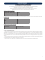
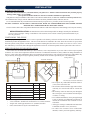
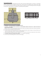
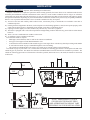
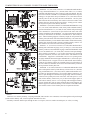
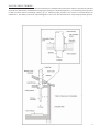
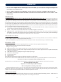
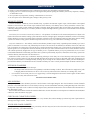
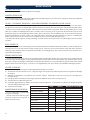
OWNER’S OPERATION AND INSTALLATION MANUAL BRECKWELL® Exceptional Heat, Outstanding Value MODEL: SPC50 Please read this entire manual before installation and use of this pellet fuelburning room heater. Failure to follow these instructions could result in property damage, bodily injury, or even death. Contact your local building or fire officials about restrictions and installation inspection requirements in your area. Save these instructions. This manual will help you to obtain efficient, dependable service from the heater, and enable you to order repair parts correctly. Keep in a safe place for future reference. SAFETY AND EPA COMPLIANCE Your pellet stove has been approved for installation in the USA and Canada. It may also be installed in a manufactured or mobile home. Your stove conforms to ASTM E 1509, 2004, and Certified to ULC S627, 2000, and(UM) 84-HUD This unit is not intended to be used as a primary source of heat. French version is available for download from the Breckwell website: http://www.Breckwell.com La version française est disponible pour téléchargement à partir du site Breckwell: http://www.breckwell.com Breckwell 227 Industrial Park Rd. P.O. Box 151 South Pittsburg, TN 37380 Phone (866) 606-8444 or (800) 750-2723 www.Breckwell.com Part No.: 852202 Rev A SAFETY PRECAUTIONS IMPORTANT: Read this entire manual before installing and operating this product. Failure to do so may result in property damage, bodily injury, or even death. Proper installation of this stove is crucial for safe and efficient operation. Install vent at clearances specified by the vent manufacturer. Do not connect the pellet vent to a vent serving any other appliance or stove. DO NOT INSTALL A FLUE DAMPER IN THE EXHAUST VENTING SYSTEM OF THIS UNIT. Use of outside air is not required for this unit, unless installed in an area with tight construction, or a mobile home. Contact your local building officials to obtain a permit and information on any additional installation restrictions or inspection requirements in your area. Do not throw this manual away. This manual has important operating and maintenance instructions that you will need at a later time. Always follow the instructions in this manual. This appliance is designed for the use of pelletized fuel that meet or exceed the standard set by the Pellet Fuel Institute(PFI). The use of other fuels will void warranty. Never use gasoline, gasoline-type lantern fuel, kerosene, charcoal lighter fluid, or similar liquids to start or ‘freshen up’ a fire in this heater. Keep all such liquids well away from the heater while it is in use. A working smoke detector must be installed in the same room as this product. Install a smoke detector on each floor of your home; incase of accidental fire from any cause it can provide time for escape. The smoke detector must be installed at least 15 feet (4,57 M) from the appliance in order to prevent unnecessary triggering of the detector when reloading. Do not unplug the stove if you suspect a malfunction. Turn the ON/OFF SWITCH to “OFF” and contact your dealer. Your stove requires periodic maintenance and cleaning (see “MAINTENANCE ”). Failure to maintain your stove may lead to improper and/or unsafe operation. Disconnect the power cord before performing any maintenance! NOTE: Turning the ON/OFF Switch to “OFF” does not disconnect all power to the electrical components of the stove. Never try to repair or replace any part of the stove unless instructions for doing so are given in this manual. All other work should be done by a trained technician. Do not operate your stove with the viewing door open. A safety concern may arise from sparks or fumes entering the room. Allow the stove to cool before performing any maintenance or cleaning. Ashes must be disposed in a metal container with a tight fitting lid. The closed container of ashes should be placed on a non-combustible surface or on the ground, well away from all combustible materials, pending final disposal. The exhaust system should be checked monthly during the burning season for any build-up of soot or creosote. Do not touch the hot surfaces of the stove. Educate all children on the dangers of a high-temperature stove. Young children should be supervised when they are in the same room as the stove. The hopper and stove top will be hot during operation; therefore, you should always use some type of hand protection when refueling your stove. A power surge protector is required. This unit must be plugged into a 110 - 120V, 60 Hz grounded electrical outlet. Do not use an adapter plug or sever the grounding plug. Do not route the electrical cord underneath, in front of, or over the heater. Do not route the cord in foot traffic areas or pinch the cord under furniture. The heater will not operate during a power outage. If a power outage does occur, check the heater for smoke spillage and open a window if any smoke spills into the room. The feed door must be closed and sealed during operation. Never block free airflow through the open vents of the unit. Keep foreign objects out of the hopper. The moving parts of this stove are propelled by high torque electric motors. Keep all body parts away from the auger while the stove is plugged into an electrical outlet. These moving parts may begin to move at any time while the stove is plugged in. Do not place clothing or other flammable items on or near this stove. When installed in a mobile home, the stove must be grounded directly to the steel chassis and bolted to the floor. WARNING—THIS UNIT MUST NOT BE INSTALLED IN THE BEDROOM (per HUD requirements). CAUTION— The structural integrity of the mobile home floor, wall, and ceiling/roof must be maintained. This appliance is not intended for commercial use. CAUTION: Burning fuel creates carbon monoxide and can be hazardous to your health if not properly vented. This appliance should not be a primary source of heat as it is possible to be down for maintenance and repairs. * This appliance is a freestanding heater. It is not intended to be attached to any type of ducting. It is not a furnace. 2 SPECIFICATIONS CONGRATULATIONS! You’ve purchased a heater from North America’s oldest manufacturer of wood burning products. By heating with wood you’re helping to CONSERVE ENERGY! Wood is our only Renewable Energy Resource. Please do your part to preserve our wood supply. Plant at least one tree each year. Future generations will thank you. HEATING SPECIFICATIONS Fuel Burn Rate* (lowest setting) 1 Lb/Hr Burn Time (lowest setting) 60 Hrs Hopper Capacity 60 lbs. ( 27kg) * Pellet size may effect the actual rate of fuel feed and burn times. Fuel feed rates may vary by as much as 20%. Use PFI listed fuel for best results. DIMENSIONS Height Width Depth Weight 29 31 29 360 ELECTRICAL SPECIFICATIONS Electrical Rating Watts 120Volt, 60Hz, 8Amp 96 FUEL CONSIDERATIONS Your pellet stove is designed to burn premium hardwood pellets that comply with Association of Pellet Fuel Industries standards. (Minimum of 40 lbs density per cubic ft, 1/4” to 5/16” diameter, length no greater than 1.5”, not less than 8,200 BTU/lb, moisture under 8% by weight, ash under 1% by weight, and salt under 300 parts per million). Pellets that are soft, contain excessive amounts of loose sawdust, have been, or are wet will result in reduced performance and excessive cleaning requirements of your appliance and flue. Store your pellets in a dry place. DO NOT store the fuel within the installation clearances of the unit or within the space required for refueling and ash removal. Doing so could result in a house fire. Do not overfire or use volatile fuels or combustibles, Doing so may cause personal and property damage hazards. 3 INSTALLATION INSTALLATION OPTIONS Read this entire manual before you install and use your pellet stove. Failure to follow instructions may result in property damage, bodily injury, or even death! (See specific installation details for clearances and other installation requirements) Your pellet stove may be installed to code in either a conventional or mobile home (see SPECIAL MOBILE HOME REQUIREMENTS). The installation must comply with the Manufactured Home and Safety Standard (HUD), CFR3280, Part 24. It is recommended that only an authorized technician install your pellet stove, preferably an NFI certified specialist. DO NOT CONNECT TO OR USE IN CONJUNCTION WITH ANY AIR DISTRIBUTION DUCTWORK UNLESS SPECIFICALLY APPROVED FOR SUCH INSTALLATIONS. The use of make-shift or other components other than stated herein could cause bodily harm, heater damage, and void your warranty. IMPROPER INSTALLATION: The manufacturer will not be held responsible for damage caused by the malfunction of a stove due to improper venting or installation. Call Customer Service and/or consult a professional installer if you have any questions. POSITIONING THE STOVE It is very important to position the stove as close as possible to the chimney, and in an area that will favor the most efficient heat distribution possible throughout the house. The stove must therefore be installed in the room where the most time is spent, and in the most spacious room possible. Recall that stoves produce radiating heat, the heat we feel when we are close to a stove. A stove also functions by convection, that is through the displacement of hot air accelerated upwards and its replacement with cooler air. FREE STANDING STOVE INSTALLATION A stove must never be installed in a hallway or near a staircase, since it may block the way in case of fire or fail to respect required clearances. It is of the utmost importance that the clearances to combustible materials be strictly adhered to during installation of the stove. Refer to the table and diagrams below for minimum required clearances. Any reduction in clearance to combustibles may only be done by means approved by a regulatory authority. Install vent at clearances specified by the vent manufacturer. Ceiling / Plafond Back wall / Arrière Mur E D Back wall / Arrière Mur E Side wall / Paroi Latérale B D C SSide de wall a / Paroi a o Latérale até a e A F Side wall / Paroi Latérale SSide de wall a / Paroi a o Latérale até a e Back wall / Arrière Mur Floor Protector / Protection de Plancher • Do not place any combustible material within 4’ (1.2m) of the front of the unit. Backwall to Stove 1 26 • The clearance between the flue pipe and a wall are valid only for vertical walls and for vertical flue Sidewall to Stove 12 305 pipe. Sidewall to Flue* 3 77 • The chimney connector must not pass through an Wall to Stove (Angled Installation) 1 26 attic or roof space, closet or similar concealed space, Wall to Flue (Angled Installation)* 3 77 or a floor, or ceiling. • For Canadian installations, where passage through Backwall to Flue* 3 77 a wall, or partition of combustible construction is * Pellet type “L” vent must have 3” (77mm) clearance “Close Clearance “double wall vent must have 6”(151mm) clearance. desired, the installation must conform to CAN/ CSA-B365. “Single wall” smoke pipe must have 18” (458mm) clearance. • A flue pipe crossing a combustible wall must have Unless stated otherwise by the vent manufacturer. a minimum clearance of 18” (457.2mm). • To reduce flue clearances from combustible materials, contact your local regulatory authority. Dimension A B C D E F • • • • 4 Inch mm FLOOR PROTECTION This heater must have a non-combustible floor protector (ember protection) installed beneath it, if the floor is of combustible material. If a floor pad is used, it should be UL listed or equal. The floor pad or non-combustible surface should be large enough to cover at least the area under the product and extend beyond the front and each side of the fuel loading and ash removal openings as shown below. A Floor Protector of ¼ inch thick is recommended for this installation. ck wall / Arrière Mur J M M K L Dimension Inch mm H* Front 6 153 J Flue rear 2 51 K** Left 6 153 L** Right 6 153 M Flue Side 2 51 ⃰ Canadian installations require 18” (457mm) ⃰ ⃰ Canadian installations require 8” (203mm) H SPECIAL MOBILE HOME REQUIREMENTS WARNING! - DO NOT INSTALL IN A SLEEPING ROOM CAUTION! - THE STRUCTURAL INTEGRITY OF THE MOBILE HOME FLOOR, WALL, AND CEILING/ROOF MUST BE MAINTAINED. In addition to the previously detailed installation requirements, mobile home installations must meet the following requirements: 1) The heater must be permanently attached to the floor. 2) The heater must be electrically grounded to the steel chassis of the mobile home with 8 GA copper wire using a serrated or star washer to penetrate paint or protective coating to ensure grounding. 3) When moving your mobile home, all exterior venting must be removed while the mobile home is being relocated. After relocation, all venting must be reinstalled and securely fastened. 4) Outside Air is mandatory for mobile home installation. See your dealer for purchasing. 5) Check with your local building officials as other codes may apply. 5 VENTILATION OUTSIDE AIR SUPPLY (Optional, unless installing in a mobile home) Adequate ventilation air is required to operate this heater. During operation, the heater draws air for combustion which can be assisted by the installation of outside combustion air inlets. However, certain weather conditions such as icing or use of kitchen exhaust fans may impact and reduce the effectiveness of vents. It is important to note that room air starvation will negatively impact the operation of the heater. Depending on your location and home construction, outside air may be necessary for optimal performance Below is a list of possible indicators that a source of outside combustion air may be required. 1) Your stove does not draw steadily, smoke rollout occurs, wood burns poorly, or back-drafts occur whether or not there is combustion present. 2) Existing fuel-fired equipment in the house, such as fireplaces or other heating appliances, smell, do not operate properly, suffer smoke roll-out when opened, or back-drafts occur whether or not there is combustion present. 3) Opening a window slightly on a calm (windless) day alleviates any of the above symptoms. 4) The house is equipped with a well-sealed vapor barrier and tight fitting windows and/or has any powered devices that exhaust house air. 5) There is excessive condensation on windows in the winter. 6) A ventilation system is installed in the house. If an outside air intake is required. • Metal pipe (solid or flexible) must be used for the outside air installation. • PVC pipe is NOT approved and should NEVER be used. • A wind shield over the termination of the outside air pipe or a 90-degree elbow or bend away from the prevailing winds MUST be used when an outside air pipe is installed through the side of a building. • The outside air termination MUST be at least 1ft (0.305m) away from the exhaust system termination. The outside air pipe on your heater is 4” (101mm) OD. The outside air connecting pipe must have an ID equal to the OD of the outside air pipe on your heater. The outside air connection used MUST NOT restrict the amount of air available to your heater. The outside air connecting pipe must be as short and free of bends as possible, and it must fit over, not inside, the outside air connection to the heater. 13.5 12.5 4.7 2.7 NOTE: DIMENSIONS TO YOUR STOVES INLET/EXHAUST PIPES ARE APPROXIMATE AND MAY VARY DEPENDING ON YOUR INSTALLATION. TYPICAL FRESH AIR TERMINATION 6 CHIMNEY CONNECTOR (STOVE PIPE) Your chimney connector and chimney must have a diameter of 4” - 6”. If this is not the case, we recommend you contact your dealer in order to insure there will be no problem with the draft. The stove pipe must be made of aluminized or cold roll steel with a minimum thickness of 0.021” or 0.53 mm. It is strictly forbidden to use galvanized steel. Your stove pipe should be assembled in such a way that the male section (crimped end) of the pipe faces down. Attach each of the sections to one another with three equidistant metal screws. Seal the joints with furnace cement. All sections installed horizontally must slope at least 1/4 inch per foot, with the upper end of the section toward the chimney. Any installation with a horizontal run of stove pipe must conform to NFPA 211. You may contact NFPA (National Fire Protection Association) and request the latest edition of the NFPA Standard 211. To insure a good draft, the total length of the stove pipe should never exceed 8’ to 10’ (2.4m to 3.04 m). (Except for cases of vertical installation, cathedral-roof style where the smoke exhaust system can be much longer and connected without problem to the chimney at the ceiling of the room). There should never be more than two 90 degrees elbows in the smoke exhaust system. Installation of a “barometric draft stabilizer” (fireplace register) on a smoke exhaust system is prohibited. Furthermore, installation of a draft damper is not recommended. With a controlled combustion wood stoves the draft is regulated upon intake of the combustion air in the stove and not at the exhaust. To Appliance 7 PELLET VENT TYPE A UL listed 4-inch or 6-inch type “PL” pellet vent exhaust system may be used for installation and attached to the pipe connector provided on the stove. Connection at stove must be sealed using Hi-Temp RTV. Use 6-inch vent if the vent height is over 12-feet or if the installation is over 2,500 feet above sea level. We recommend the use of Simpson Dura-Vent® or Metal-Fab® pipe (if you use other pipe, consult your local building codes and/or building inspectors). Do not use Type-B Gas Vent pipe or galvanized pipe with this unit. The pellet vent pipe is designed to disassemble for cleaning and should be checked several times during the burning season. Pellet vent pipe is not furnished with the unit and must be purchased separately. PELLET VENT INSTALLATION The installation must include a clean-out tee to enable collection of fly ash and to permit periodic cleaning of the exhaust system. 90-degree elbows accumulate fly ash and soot, thereby reducing exhaust flow and performance of the stove. Each elbow or tee reduces draft potential by 30% to 50%. All joints in the vent system must be fastened by at least 3 screws, and all joints must be sealed with Hi-Temp RTV silicone sealant to be airtight. The area where the vent pipe penetrates to the exterior of the home must be sealed with silicone or other means to maintain the vapor barrier between the exterior and the interior of the home. Vent surfaces can get hot enough to cause burns if touched. Noncombustible shielding or guards may be required. PELLET VENT TERMINATION Do not terminate the vent in an enclosed or semi-enclosed area, such as. carport, garage, attic, crawl space, under a sundeck or porch, narrow walkway, or any other location that can build up a concentration of fumes. Termination in one of these areas can also lead to unpredictable pressure situations with the appliance; and could result in improper performance and/or malfunction. The termination must exhaust above the outside air inlet elevation. The termination must not be located where it will become plugged by snow or other materials. DO NOT CONNECT THIS UNIT TO A CHIMNEY FLUE SERVING ANOTHER APPLIANCE. The following recommendations may be useful for the installation of your chimney: • It must rise above the roof at least 3’ (0.9m) from the uppermost point of contact. • The exterior portion should be double or triple wall pipe to ensure proper draft. • The chimney must exceed any part of the building or other obstruction within a 10’ (3.04m) distance by a height of 2’ (0.6m). • Installation of an interior chimney is always preferable to an exterior chimney. The interior chimney will be hotter than an exterior chimney that is being cooled by the ambient air outside the house. Therefore the gas which circulates will cool slower, thus reducing the build-up of creosote and the risk of chimney fires. • The draft caused by the tendency for hot air to rise will be increased with an interior chimney. • Using a fire screen at the extremity of the chimney requires regular inspection in order to insure that it is not obstructed thus blocking the draft, and it should be cleaned when used regularly. TYPE HT CHIMNEY Your wood stove may be hooked up with a factory built or masonry chimney. If you are using a factory built chimney, it must comply with UL 103 or CSA-B365 standard; therefore it must be a Type HT (2100°F). It is extremely important that it be installed according to the manufacturer’s specifications. If you are using a masonry chimney, it is important that it be built in compliance with the specifications of the National Building Code. It must be lined with fire clay bricks, metal or clay tiles sealed together with fire cement. (Round flues are the most efficient). The interior diameter of the chimney flue must be 4”-6”. A flue which is too small may cause draft problems, while a large flue favors rapid cooling of the gas, and hence the build-up of creosote and the risk of chimney fires. Note that it is the chimney and not the stove which creates the draft effect; your stove’s performance is directly dependent on an adequate draft from your chimney. 8 MASONRY CHIMNEY : Ensure that a masonry chimney meets the minimum standards of the National Fire Protection Association (NFPA) by having it inspected by a professional. Make sure there are no cracks, loose mortar or other signs of deterioration and blockage. Have the chimney cleaned before the stove is installed and operated. When connecting the stove through a combustible wall to a masonry chimney, special methods are needed as explained in the “Combustible Wall Chimney Connector Pass-Throughs” Section. 9 COMBUSTIBLE WALL CHIMNEY CONNECTOR PASS-THROUGHS Method A. 12” (304.8 mm) Clearance to Combustible Wall Member: Using a minimum thickness 3.5” (89 mm) brick and a 5/8” (15.9 mm) minimum wall thickness clay liner, construct a wall pass-through. The clay liner must conform to ASTM C315 (Standard Specification for Clay Fire Linings) or its equivalent. Keep a minimum of 12” (304.8 mm) of brick masonry between the clay liner and wall combustibles. The clay liner shall run from the brick masonry outer surface to the inner surface of the chimney flue liner but not past the inner surface. Firmly grout or cement the clay liner in place to the chimney flue liner. Method B. 9” (228.6 mm) Clearance to Combustible Wall Member: Using a 6” (152.4 mm) inside diameter, listed, factory-built Solid-Pak chimney section with insulation of 1” (25.4 mm) or more, build a wall pass-through with a minimum 9” (228.6 mm) air space between the outer wall of the chimney length and wall combustibles. Use sheet metal supports fastened securely to wall surfaces on all sides, to maintain the 9” (228.6 mm) air space. When fastening supports to chimney length, do not penetrate the chimney liner (the inside wall of the Solid-Pak chimney). The inner end of the Solid-Pak chimney section shall be flush with the inside of the masonry chimney flue, and sealed with a non-water soluble refractory cement. Use this cement to also seal to the brick masonry penetration. Method C. 6” (152.4 mm) Clearance to Combustible Wall Member: Starting with a minimum 24 gauge (.024” [.61 mm]) 6” (152.4 mm) metal chimney connector, and a minimum 24 gauge ventilated wall thimble which has two air channels of 1” (25.4 mm) each, construct a wall pass-through. There shall be a minimum 6” (152.4) mm separation area containing fiberglass insulation, from the outer surface of the wall thimble to wall combustibles. Support the wall thimble, and cover its opening with a 24-gauge minimum sheet metal support. Maintain the 6” (152.4 mm) space. There should also be a support sized to fit and hold the metal chimney connector. See that the supports are fastened securely to wall surfaces on all sides. Make sure fasteners used to secure the metal chimney connector do not penetrate chimney flue liner. Method D. 2” (50.8 mm) Clearance to Combustible Wall Member: Start with a solid-pak listed factory built chimney section at least 12” (304 mm) long, with insulation of 1” (25.4 mm) or more, and an inside diameter of 8” (2 inches [51 mm] larger than the 6” [152.4 mm] chimney connector). Use this as a pass-through for a minimum 24-gauge single wall steel chimney connector. Keep solid-pak section concentric with and spaced 1” (25.4 mm) off the chimney connector by way of sheet metal support plates at both ends of chimney section. Cover opening with and support chimney section on both sides with 24 gauge minimum sheet metal supports. See that the supports are fastened securely to wall surfaces on all sides. Make sure fasteners used to secure chimney flue do not penetrate flue liner. NOTES: Connectors to a masonry chimney, excepting method B, shall extend in one continuous section through the wall pass-through system and the chimney wall, to but not past the inner flue liner face. A chimney connector shall not pass through an attic or roof space, closet or similar concealed space, or a floor, or ceiling. 10 FACTORY BUILT CHIMNEY : When a metal prefabricated chimney is used, the manufacturer’s installation instructions must be followed. You must also purchase (from the same manufacturer) and install the ceiling support package or wall pass-through and “T” section package, firestops (where needed), insulation shield, roof flashing, chimney cap, etc. Maintain proper clearance to the structure as recommended by the manufacturer. The chimney must be the required height above the roof or other obstructions for safety and proper draft operation. 11 THERMOSTAT INSTALLATION & OPERATION THERMOSTAT REQUIREMENTS The will accept a non-voltage carrying thermostat. Do not use a thermostat with a transformer THERMOSTAT INSTALLATION 1. 2. 3. 4. Unplug the stove. Remove controller from the stove. Remove the black jumper from J8. Attach the thermostat wires to the blue TSTAT Terminal. THERMOSTAT OPERATION After the stove is running when the thermostat calls for heat the heat level will go to the level that you set on the controller. It is recommended that you set the heat level to slightly above what is needed. When the thermostat is satisfied then the stove will return to idle until heat is called for again. TO ADJUST THE THERMOSTAT IDLE HEAT LEVEL 1. 2. 3. 4. 12 When the stove is in run mode, scroll through the main menu until you see “set idle heat level”. Press enter to select. Use the left and right arrows to adjust the temperature, just as up would control the standard heat level. Press menu to return to standard operation, or it will time out after a few seconds. OPERATION DO NOT USE CHEMICALS OR FLUIDS TO START THE FIRE - Never use gasoline, gasoline-type lantern fuel, kerosene, charcoal lighter fluid, or similar liquids to start or “freshen up” a fire in this stove. Keep all such liquids well away from the stove while it is in use. DO NOT BURN GARBAGE OR FLAMMABLE FLUIDS SUCH AS GASOLINE, NAPHTHA, OR ENGINE OIL. HOT WHILE IN OPERATION. KEEP CHILDREN, CLOTHING AND FURNITURE AWAY. CONTACT MAY CAUSE SKIN BURNS. PROPER FUEL THIS STOVE IS APPROVED FOR BURNING PELLETIZED WOOD FUEL ONLY ! Factory-approved pellets are those 1/4” or 5/16” in diameter and not over 1” long. Longer or thicker pellets sometimes bridge the auger flights, which prevents proper pellet feed. Burning wood in forms other than pellets is not permitted. It will violate the building codes for which the stove has been approved and will void all warranties. The design incorporates automatic feed of the pellet fuel into the fire at a carefully prescribed rate. Any additional fuel introduced by hand will not increase heat output but may seriously impair the stoves performance by generating considerable smoke. Do not burn wet pellets. The stove’s performance depends heavily on the quality of your pellet fuel. Avoid pellet brands that display these characteristics: 1) Excess Fines – “Fines” is a term describing crushed pellets or loose material that looks like sawdust or sand. Pellets can be screened before being placed in hopper to remove most fines. 2) Binders – Some pellets are produced with materials to hold them together, or “bind” them. 3) High ash content – Poor quality pellets will often create smoke and dirty glass. They will create a need for more frequent maintenance. You will have to empty the burn pot plus vacuum the entire system more often. Poor quality pellets could damage the auger. We cannot accept responsibility for damage due to poor quality pellet. PRE-START-UP CHECK Clean the firebox. Clean door glass, if necessary (a dry cloth or paper towel is usually sufficient). Never use abrasive cleaners on the glass or door. Check fuel in the hopper and refill if necessary. It is recommended that you preform a system sensor check prior to initial and seasonal start up (see trouble shooting). BUILDING A FIRE Never use a grate or other means of supporting the fuel. Use only the burn pot supplied with this heater. Hopper lid must be closed in order for the unit to feed pellets. During the start-up period: 4) Make sure burn pot is free of pellets. Turn the unit on. It will then begin to feed pellets into the burnpot. 5) Then pour several cups of pellets in the burnpot so that pellets fill it to the brim. Adjust the nozzle to point downward and centered over the burnpot. 6) Add a maximum of one (1) tablespoon of approved pellet ignitor gel. 7) Close the air control damper. 8) Lift the trap door lever. 9) Light the pellets. 10) Adjust the combustion air damper until the flame spreads across the burnpot. 11) The stove will now enter START-UP mode. The controller will alert you every ten minutes until the stove enters run mode. DO NOT Leave the stove unattended while in START-UP mode. 12) When the stove enters RUN mode the temperature can be adjusted. The default temperature will be the last set point. DO NOT open the viewing door. Adjust the air control damper to spread the flame. DO NOT add pellets to the burn pot by hand. NOTE: During the first few fires, your stove will emit an odor as the high temperature paint cures or becomes seasoned to the metal. Maintaining smaller fires will minimize this. Avoid placing items on stove top during this period because paint could be affected. Animals / People with lung problems should take caution during the first few fires. TRAP DOOR LEVER The trap door lever is on the back left side of the stove. It is used to open the trap door when starting the stove. In the event of a power failure the trap door will close preventing smoke from coming out of the unit. 13 OPERATION DAMPER CONTROL The damper control lever is located on the lower left side of the stove. The damper adjusts the combustion air. This control is necessary due to the varied burn characteristics of individual installations, different pellet brands, and pellet feed rates. It allows you to improve the efficiency of your stove. Providing correct combustion air will reduce the frequency of cleaning your glass door and prevent the rapid buildup of creosote inside your stove and chimney. You should adjust the damper based on the fire’s appearance. A low, reddish, dirty fire can be improved by pulling the damper slightly out away from the stove. A “blow torch” fire can be improved by pushing the damper in toward the stove. As a general rule, on lower feed rate settings, the damper should be farther to the right closing it off. On higher feed rates, the damper should be open more by having it set more towards the left. Through trial and error, you will find the best setting. Consult your dealer if you need help. HOPPER COOLING FAN When you plug in the stove the hopper cooling fan will begin running. It always runs when the Control Board is operating. It is a 35 to 85 CFM low amperage fan designed for extended service and quiet operation. IF STOVE RUNS OUT OF PELLETS The stove will go into shutdown mode. The fire will go out and the auger motor and blowers will run until the stove cools. This will take 30 minutes or longer depending on the heat remaining in the appliance. After the stove components stop running all lights on the display will go out. REFUELING • The hopper and stove top will be hot during operation; therefore, you should always use some type of hand protection when refueling your stove. • Never place your hand near the auger while the stove is in operation. We recommend that you not let the hopper drop below ¼ full. KEEP HOPPER LID CLOSED AT ALL TIMES EXCEPT WHEN REFILLING. DO NOT OVERFILL HOPPER. SHUTDOWN PROCEDURE If you must shutdown the stove without running out the fuel, just hold the power button for several seconds and confirm shutdown when asked on the screen. DO NOT UNPLUG THE STOVE AND KEEP THE HOPPER CLOSED. All motors will stop when power is manualy turned off. 1. Your stove is equipped with multiple high temperature thermodiscs. The safety switches operate as shown. A. The BURN BACK sensor turns the auger on high if heat is sensed in the auger feed tube. B. The HOPPER OVERHEAT sensor shuts the stove down to prevent a hopper fire. C. The FUEL sensor shuts the stove off when the fuel is exhausted. (This is a convenience feature) NOTE: The manufacturer recommends that you call your dealer if an overheat occurs as this may indicate a more serious problem. WARNING: NEVER SHUT DOWN THIS UNIT BY UNPLUGGING IT FROM THE POWER SOURCE. PANEL CONTROLS The blowers and automatic fuel supply are controlled from a panel on the side of the SPC50. The control panel functions are a follows. A. • B. • C. • D. • 14 ON/OFF SWITCH (“POWER” BUTTON) The power button turns the stove on. MENU BUTTON This button will cycle through the different menus available. ENTER This button will confirm the current selection. SCROLL BUTTONS These buttons allow you to navigate through the menus by selecting the next item on the menu. In the appropriate direction. The left and right buttons also adjust the temperature setting MAINTENANCE Failure to clean and maintain this unit as indicated can result in poor performance and safety hazards. Unplug your stove’s electrical cord prior to removing the back panel or opening the exhaust system for any inspection, cleaning, or maintenance work. Never perform any inspections, cleaning, or maintenance on a hot stove. Do not operate stove with broken glass, leakage of flue gas may result. EXHAUST SYSTEM Creosote Formation – When any wood is burned slowly, it produces tar and other organic vapors, which combine with expelled moisture to form creosote. The creosote vapors condense in the relatively cool chimney flue or a newly started fire or from a slowburning fire. As a result, creosote residue accumulates on the flue lining. When ignited, this creosote makes an extremely hot fire, which may damage the chimney or even destroy the house. Despite their high efficiency, pellet stoves can accumulate creosote under certain conditions. Soot and Fly Ash: Formation and Need for Removal – The products of combustion will contain small particles of flyash. The flyash will collect in the exhaust venting system and restrict the flow of the glue gases. Incomplete combustion, such as occurs during startup, shutdown, or incorrect operation of the room heater will lead to some soot formation which will collect in the exhaust venting system. The exhaust venting system should be inspected at least once every year to determine if cleaning is necessary. Inspection and Removal – The chimney connector and chimney should be inspected by a qualified person annually or per ton of pellets to determine if a creosote or fly ash build-up has occurred. If creosote has accumulated, it should be removed to reduce the risk of a chimney fire. Inspect the system at the stove connection and at the chimney top. Cooler surfaces tend to build creosote deposits quicker, so it is important to check the chimney from the top as well as from the bottom. The creosote should be removed with a brush specifically designed for the type of chimney in use. A qualified chimney sweep can perform this service. It is also recommended that before each heating season the entire system be professionally inspected, cleaned and, if necessary, repaired. To clean the chimney, disconnect the vent from the stove. Establish a routine for the fuel, wood burner and firing technique. Check daily for creosote build-up until experience shows how often you need to clean to be safe. Be aware that the hotter the fire the less creosote is deposited, and weekly cleaning may be necessary in mild weather even though monthly cleaning may be enough in the coldest months. Contact your local municipal or provincial fire authority for information on how to handle a chimney fire. Have a clearly understood plan to handle a chimney fire. INTERIOR CHAMBERS • • Burn Pot: Periodically clean the burn pot. • The burnpot and feed tube elbow will gradually accumulate a buildup of carbon. This will need to be chipped away with a chipping hammer and blade screw driver. Do not use any other tools for this function, stove damage may result. If a vacuum is used to clean your stove, we suggest using a vacuum designed for ash removal. Some regular vacuum cleaner (i.e. shop vacs) may leak ash into the room. DO NOT VACUUM HOT ASH! ASH DISPOSAL Disposal of Ashes-Ashes should be placed in a metal container with a tight fitting lid. The closed container of ashes should be placed on a noncombustible floor or on the found, well away from all combustible materials, pending final disposal. If the ashes are disposed of by burial in soil or otherwise locally dispersed, they should be retained in the closed container until all cinders have been thoroughly cooled. Remove ashes when unit has cooled. The container shall not be used for other trash or waste disposal. If combined with combustible substances, ashes and embers may ignite. CHECK AND CLEAN THE HOPPER Check the hopper periodically to determine if there is any sawdust (fines) that is building up in the feed system or pellets that are sticking to the hopper surface. Clean as needed. DOOR AND GLASS GASKETS Inspect the door and glass window gaskets periodically. The door may need to be removed to have frayed, broken, or compacted gaskets replaced by your authorized dealer. 15 MAINTENANCE BLOWER MOTORS Clean the air holes on the motors of the blowers annually. PAINTED SURFACES Painted surfaces may be wiped down with a damp cloth. If scratches appear or you wish to renew your paint, contact your authorized dealer to obtain suitable high-temperature paint. GLASS - CLEANING, REMOVAL, AND REPLACEMENT OF BROKEN DOOR GLASS Cleaning - We recommend using a high quality glass cleaner. Should a buildup of creosote or carbon accumulate, you may wish to use 000 steel wool and water to clean the glass. DO NOT use abrasive cleaners. DO NOT perform the cleaning while the glass is HOT. In the event you need to replace the glass, remove the screws, glass retainers and gasket. While wearing leather gloves (or any other gloves suitable for handling broken glass), carefully remove any loose pieces of glass from the door frame. Dispose of all broken glass properly. ONLY high temperature ceramic glass of the correct size and thickness may be used. DO NOT substitute alternative materials for the glass. Contact your authorized dealer to obtain this glass. Re-install the new glass by re-attaching the gasket, retainers and screws, be careful not to over tighten the screws for this could damage the glass. DO NOT abuse the door glass by striking, slamming, or similar trauma. Do not operate the stove with the glass removed, cracked, or broken. FALL START UP Prior to starting the first fire of the heating season, check the outside area around the exhaust and air intake systems for obstructions. Clean and remove any fly ash from the exhaust venting system. Clean any screens on the exhaust system and on the outside air intake pipe. Turn all of the controls on and make sure that they are working properly. This is also a good time to give the entire stove a good cleaning throughout. SPRING SHUTDOWN After the last burn in the spring, remove any remaining pellets from the hopper and the auger feed system. Scoop out the pellets and then run the auger until the hopper is empty and pellets stop flowing (this can be done by pressing the “ON” button with the viewing door open). Vacuum out the hopper. Thoroughly clean the burn pot and firebox. It may be desirable to spray the inside of the cleaned hopper with an aerosol silicone spray if your stove is in a high humidity area. The exhaust system should be thoroughly cleaned. AUGER CLEANING It is recommended that the auger be cleaned and polished monthly or as needed. 1) Turn the unit off, allow the unit to cool, empty the hopper and run the auger untill all pellets have been pushed out throught the burnpot. 2) Add three (3) tablespoons of vegetable oil to 6-8 ounces of pellets. Ensure there is not a lot of excess oil as it will drip out of the auger tubing. 3) Pour the pellets into the bottom of the hopper and add an additional 60-80 ounces of pellets on top. 4) Turn the unit on but DO NOT light a fire. 5) It will take approximately 10 minutes for the pellets to fill the auger tube. As the pellets are pushed to the burnpot the pellets will clean and polish the auger tube. 6) Vacuum out the burnpot. Daily Weekly Monthly or as needed Burn Pot Combustion Chamber Use the following as a guide under Ashes average use conditions. Gaskets around door and door glass Interior Chambers should be inspected and repaired or Blower Blades replaced when necessary. Vent System Gaskets Glass Auger Hopper (end of season) Check Brushed Check MAINTENANCE SCHEDULE 16 Wiped Empty Vacuumed Vacuumed / Brushed Cleaned Inspected Cleaned Emptied and Polished Emptied and vacuumed TROUBLE SHOOTING GUIDE When your stove acts out of the ordinary, the first reaction is to call for help. This guide may save time and money by enabling you to solve simple problems yourself. Problems encountered are often the result of only five factors: 1) poor fuel; 2) poor operation or maintenance; 3) poor installation; 4) component failure; 5) factory defect. You can usually solve those problems related to 1 and 2. Your dealer can solve problems relating to 3, 4 and 5. For the sake of troubleshooting and using this guide to assist you, you should look at your control board display to see what the error is. Disconnect the power cord before performing any maintenance! NOTE: Turning the ON/OFF Switch to “OFF” does not disconnect all power to the electrical components of the stove. Never try to repair or replace any part of the stove unless instructions for doing so are given in this manual. All other work should be done by a trained technician. SYSTEM SENSOR CHECK PROCEDURE To preform a system sensor check the stove must be plugged in, cool and off. 1) Turn the stove on After a few seconds the controller will ask a series of questions. Answer the questions as shown to proceed with the system check. 2) Q1) Is there a fire in the burnpot? A1) No (press the left or down arrow key) 3) Q2) Do you want to start a fire? A2) No (press the left or down arrow key) 4) Q3) You can start a fire latter. A3) OK (press any arrow key) 5) You should now see the main menu on the controller. 6) Press menu four (4) times until you see “Sensor info” 7) Press up to select sensor info. 8) You should now see the sensor status. Note that all the sensors say OK except Fuel and Trap Door. 9) To check the trap door sensor, manually hold the trap door open with the trap door handle on the back of the stove. Once the door is open the sensor status should change to OK. 10) Open the Hopper lid to check that the sensor is working correctly. The status should change to “XX” when the hopper lid is open. 11) To exit the system sensor check press menu until the controller asks if you want to start a fire. 17 TROUBLE SHOOTING GUIDE Fuel Feed Problems Possible Causes: Lack Of Fuel In Burnpot To Much Fuel In Burnpot Possible Remedies: (Unplug Stove First When Possible) FUEL The hopper is out of pellets. The hopper safety switch has failed or hopper is open. Refill the hopper. When operating the unit, be sure the hopper lid is closed so that the hopper safety switch will activate. Check the wires leading from the hopper safety switch to the control panel and auger motor for secure connections. Use a continuity tester to test the hopper safety switch; replace if necessary. Fuel other than wood pellets is being burned in the stove. This pellet stove is designed and tested to use wood pellets. Check for signs of fuel other than wood pellets. No other types of fuel have been approved for this pellet stove. If there are signs of other types of fuel being used, stop using them immediately. Bad pellets. (Causes glass to “soot” up at a very fast rate only) The brand of pellets or the batch of pellets that are being used may be of poor quality. If possible, try a different brand of pellets. You might also want to try a brand that is made from a different type of wood (softwood vs. Hardwood). Different woods have different characteristics when being burned. AUGER Auger jam. The auger motor has failed. Controls / Operation Problems Possible Causes: Start by emptying the hopper. Then remove the auger motor remove the auger shaft inspection plate in the hopper so that you can see the auger shaft. After you have removed the shaft, inspect it for bent flights, burrs, or broken welds. Remove any foreign material that might have caused the jam. Also, check the auger tube for signs of damage such as burrs, rough spots, or grooves cut into the metal that could have caused a jam. Remove the auger motor from the auger shaft and try to run the unit. If the motor will turn, the shaft is jammed on something. If the motor will not turn, the motor is bad. Thermostat malfunction Possible Remedies: (Unplug Stove First When Possible) CONTROL / OPERATION The thermostat is not controling the stove. The t-stat sensor has come unplugged from the control board. Check to see if the sensor is unplugged. If the sensor is not unplugged, then the sensor is damaged, has a short or the jumper has been left on the board. If the sensor is damaged or has a short, it will need to be replaced. The stove is being left on the highest setting for extended If operating the heater on the highest heat setting, the room periods of time. temperature could increase enough and lead to potential overheating situations. If this happens, try operating at a lower heat setting. 18 TROUBLE SHOOTING GUIDE WIRING & CONTROLS Loose wire or connector. Check all wires and connectors that connector to the auger motor, high limit switch, and the molex connector. Bad control board. If the fuse is good, the wires and connectors check out good, and the high limit switch did not trip, test for power going to the auger motor. If there is not a full current going to the auger motor when the fuel feed light is on, you have a bad control board. If the auger motor runs constantly, the board is bad. Circuit board malfunction. The control board is not sending power to the fuel sensor There should be a 5-volt (approximately) current going to the thermodisc or other auger system components. fuel sensor thermodisc after the stove has been on for 10 minutes. The proof of fire (Fuel sensor) thermodisc has came upluged. Check the (Fuel sensor) thermodisc to see if the wires are connected properly. The proof of fire (Fuel sensor) thermodisc has malfunctioned. Temporarily bypass the Fuel sensor thermodisc by disconnecting the two wires and connecting them with a short piece of wire. Then plug the stove back up. If the stove comes on and works, you need to replace the Fuel sensor thermodisc. This is for testing only. Do not leave the thermodisc bypassed. Your blowers will never shut off and if the fire went out the auger will continue to feed pellets until the hopper is empty if you leave the fuel sensor thermodisc bypassed. A power surge, spike, or voltage drop could cause the high limit switch to trip. Use a surge protector. Power surge or brown out situation. 19 TROUBLE SHOOTING GUIDE Air Supply / Ventilation Problems Possible Causes: Glass “Soot’s” Up At A Very Fast Rate, Flame Is Lazy, Dark, And Has Black Tips , After Stove Has Been On For A While, The Burnpot Overfills Possible Remedies: (Unplug Stove First When Possible) EXHAUST / VENTILATION There is a leak in the vent pipe system. Vent pipe installed improperly. Inspect all vent pipe connections. Make sure they are sealed with RTV silicone that has a temperature rating on 500 degree f or higher. Also, seal joints with ul-181-ap foil tape. Make sure the square to round adapter piece on the combustion blower has been properly sealed with the same rtv. Check to make sure the vent pipe has been installed according to the criteria in the owner’s manual. Stove or vent pipe is dirty, which restricts airflow through the Follow all cleaning procedure in the maintenance section of burnpot. the owner’s manual. COMBUSTION AIR The air inlet, or the interior chambers have a partial blockage. Follow all cleaning procedures in the maintenance section of the owner's manual. Blockage in air intake pipe. Visually inspect the air intake pipe that leads into the burnpot for foreign material. The firebox is not properly sealed. Make sure the door is closed and that the gasket is in good shape. AIR DAMPER The air damper is too far open for a low feed setting. Air damper is set too far closed for a higher setting. Air damper is broken. 20 If on the low setting, you may need to close the damper all the way. Pull the damper knob to the left and try to burn the unit again. Visually inspect the damper assembly. Make sure the damper plate is attached to the damper rod. When the damper rod is moved, the plate should move with it. TROUBLE SHOOTING GUIDE BLOWER The gasket on the blower has gone bad. Inspect both gaskets on the combustion blower to make sure they are in good shape. Replace if damaged. The blower is overheating and tripping the internal temperature Clean any dust off of the windings and fan blades. If cleaning shutoff. the blower does not help, the blower may be bad. Blower failure. With the stove on, check to see if the blower is running. If it is not, you will need to check for power going to the blower. It should be a full current. If there is power, the blower is bad. If there is not the control board may be malfunctioning. WIRING & CONTROLS Circuit board malfunction. 7. Control board not sending power to combustion blower. Test the current going to the convection blower. If there is power being sent to the blower when it is shut off, then the control board is fine. If there is not power being sent to the blower when it shuts off during operation, then you have a bad control board. If there is no current going to the combustion blower, check all wire connections. If all wires are properly connected, you have a bad control board. 9. Air switch has failed. To test the air switch, you will need to disconnect the air hose from the body of the stove. With the other end still attached to the air switch, very gently blow on the loose end of the hose (you may want to remove the hose entirely off the stove and the air switch first and make sure it is clear). If you hear a click, the air switch is working. Be careful too much vacuum can damage the air switch. 1. Airflow switch hose or stove attachment pipes for hose are Unhook air hose from the air switch and blow through it. If air blocked. flows freely, the hose and tube are fine. If air will not flow throw the hose, use a wire coat hanger to clear the blockage. 5. The airflow switch wire connections are bad. 8. Control board not sending power to air switch. Check the connectors that attach the blue wires to the air switch. There should be a 5-volt current (approximately) going to the air switch after the stove has been on for 30 seconds. 21 PARTS LIST IN ORDER TO MAINTAIN WARRANTY, COMPONENTS MUST BE REPLACED USING ORIGINAL MANUFACTURERS PARTS PURCHASED THROUGH YOUR DEALER OR DIRECTLY FROM THE APPLIANCE MANUFACTURER. USE OF THIRD PARTY COMPONENTS WILL VOID THE WARRANTY. Part No. 892300 40599 892301 40600 892302 88087 88066 892303 892304 892308 892305 892306 892307 892309 40601 892310 892311 88033 892312 892319 892321 892322 892320 40602 892314 892315 892316 892317 892318 892313 80664 80665 80491 80661 80663 80462 80461 80249 80610 80462 892325 22 Description Qty. Main Stove Body (Specify Color) Legs (Specify Color) Front Door Assembly (Specify Color) Front Door (Specify Color) Glass Glass Gasket Door Gasket Glass Retainers Hinge Pins Handle Assembly Cam Plastic Knob Brass Handle Body W/ Stud Side Door Assembly (Specify Color) Side Door (Specify Color) Handle Hinge Pins Rope Gasket Handle Catch Auger Assembly Auger Body Auger Auger Bushing/Bearing Assembly Baffles Primary/Secondary Air Tube Assembly Tube Weldment Primary Air Bushing Primary Air Nozzle Air Shutter Assembly Touchup Paint (Specify Color) 4” Fan Electromagnet 12-Volt Microswitch Pressure Switch Hopper Thermodisc Receptacle, 3-Prong Cord, 3-Prong Burn Back Thermodisc Proof of Fire Thermodisc Auger Motor Fan Cover Grill 1 4 1 1 1 1 1 7 2 1 1 1 1 1 1 1 2 1 1 1 1 1 1 2 1 1 1 1 1 1 2 1 1 1 1 1 1 1 1 1 1 WIRING DIAGRAM J8 23 NOTES 24 NOTES 25 HOW TO ORDER REPAIR PARTS This manual will help you obtain efficient, dependable service from your PELLET STOVE, and enable you to order repair parts correctly. Keep this manual in a safe place for future reference. When writing, always give the full model number which is on the nameplate attached to the heater. When ordering repair parts, always give the following information as shown in this list: 1. The part number 2. The part description 3. The model number: ________________________________________ 4. The serial number: _________________________________________ BRECKWELL® Exceptional Heat, Outstanding Value 26 Breckwell 227 Industrial Park Rd. P.O. Box 151 South Pittsburg, TN 37380 Phone (866) 606-8444 www.Breckwell.com CUT HERE WARRANTY INFORMATION CARD Name__________________________________________ Telephone #: (_____)_____________ City____________________________________________ State_______ Zip_________________ Email Address __________________________________________________________________ Model # of Unit________________________________ Serial #___________________________ Fuel Type: □ Wood □Coal □Pellet □Gas □Other _________________________ Place of Purchase (Retailer)______________________________________________________ City____________________________________________ State_______ Zip_________________ If internet purchase, please list website address___________________________________ Date of Purchase _______________________________________________________________ Reason for Purchase: □Decoration □Alternative Heat □Cost □Main Heat Source □Other _________________________ What was the determining factor for purchasing your new appliance?_______ I have read the owner’s manual that accompanies this unit and fully understand the: Installation □ Print Name Operation □ and Maintenance □ Signature of my new appliance. Date Please attach a copy of your purchase receipt. Warranty not valid without a Proof of Purchase. CUT HERE Warranty information must be received within 30 days of original purchase. Detach this page from this manual, fold in half with this page to the inside and tape together. Apply a stamp and mail to the address provided. You may use an envelope if you choose. You may register online by going to www.Breckwell.com All information submitted will be kept strictly confidential. Information provided will not be sold for advertising purposes. Contact information will be used solely for the purpose of product notifications. 27 CUT HERE Fold Here Fold Here Breckwell 227 Industrial Park Rd. P.O. Box 151 South Pittsburg, TN 37380 USA 28 CUT HERE PLACE STAMP HERE