1
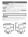
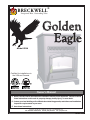
BRECKWELL® Exceptional Heat, Outstanding Value Golden Eagle Model 5520 Certified for installations in the USA and Canada. C CM US Owner’s Manual Please read this entire manual before installation and use of this appliance. Failure to follow these instructions could result in property damage, bodily injury, or even death. Contact your local building or fire officials about obtaining permits, restrictions and installation inspection requirements in your area. Save these instructions. Breckwell • P.O. Box 750 • Bridgeport, AL 35740 • www.BRECKWELL.com FOR TECHNICAL ASSISTANCE: PHONE: (866) 606-8444 FAX: (423) 837-2129 Part No.: 851907 Table of Contents TABLE OF CONTENTS............................................................................................... 2 Warranty registration . ...............................................................................3-4 Safety Precautions............................................................................................ 5 Specifications........................................................................................................ 6 Heating Specifications...................................................................................................6 Dimensions....................................................................................................................6 Electrical Specifications.................................................................................................6 Fuel Considerations.......................................................................................................6 Safety and EPA Compliance..........................................................................................6 Installation Options........................................................................................................7 Floor Protection.............................................................................................................7 Clearances ...................................................................................................................8 Venting Requirements...................................................................................................9 Maximum Venting Distance...........................................................................................9 Pellet Vent Type.............................................................................................................9 Pellet Vent Installation...................................................................................................9 Pellet Vent Termination..................................................................................................9 Vent Termination Clearances.......................................................................................10 Through the Wall Installation.......................................................................................11 Through the Roof/Ceiling Installation..........................................................................11 Outside Air Supply.......................................................................................................12 Special Mobile Home Requirements...........................................................................12 Unit Preparation...........................................................................................................14 Proper Fuel..................................................................................................................14 Pre Start-up Check......................................................................................................14 Building a Fire..............................................................................................................14 The HOT ROD Automatic Fire Starter.........................................................................15 Damper Control...........................................................................................................15 Opening Door..............................................................................................................15 Room Air Fan...............................................................................................................15 Re-Starting a Warm Stove...........................................................................................15 If Stove Runs Out of Fuel............................................................................................15 Refueling.....................................................................................................................15 Shut Down Procedure.................................................................................................15 Safety Features...........................................................................................................15 Exhaust System...........................................................................................................17 Interior Chambers........................................................................................................17 Ash Disposal................................................................................................................17 Check and Clean the Hopper......................................................................................17 Main Door Gaskets......................................................................................................17 Blower Motors..............................................................................................................17 Painted Surfaces.........................................................................................................17 Glass...........................................................................................................................18 Fall Start-Up................................................................................................................18 Spring Shut Down........................................................................................................18 Maintenance Schedule................................................................................................18 Installation . ......................................................................................................... 7 CONTROL PANEL..................................................................................................... 13 Operation.........................................................................................................14-15 Thermostat Installation................................................................................ 16 Maintenance....................................................................................................17-18 Trouble Shooting.........................................................................................19-23 Repair Parts Diagram/LIST.........................................................................24-26 Wiring Diagram.................................................................................................... 27 2 CUT HERE " WARRANTY INFORMATION CARD Name__________________________________________ Telephone #: (_____)_____________ City____________________________________________ State_______ Zip_________________ Email Address __________________________________________________________________ Model # of Unit________________________________ Serial #___________________________ Fuel Type: qWood qCoal qPellet qGas qOther _________________________ Place of Purchase (Retailer)______________________________________________________ City____________________________________________ State_______ Zip_________________ If internet purchase, please list website address___________________________________ Date of Purchase _______________________________________________________________ Reason for Purchase: qAlternative Heat qDecoration qCost qMain Heat Source qOther _________________________ What was the determining factor for purchasing your new USSC appliance?_______ I have read the owner’s manual that accompanies this unit and fully understand the: Installation qOperation q and Maintenance q of my new USSC appliance. Print Name Signature Date Please attach a copy of your purchase receipt. Warranty not valid without a Proof of Purchase. " CUT HERE Warranty information must be received within 30 days of original purchase. Detach this page from this manual, fold in half with this page to the inside and tape together. Apply a stamp and mail to the address provided. You may use an envelope if you choose. You may register online by going to www.breckwell.com All information submitted will be kept strictly confidential. Information provided will not be sold for advertising purposes. Contact information will be used solely for the purpose of product notifications. 3 CUT HERE " Ê Fold Here Fold Here É 4 " Breckwell P.O. Box 750 Bridgeport, AL 35740 CUT HERE Place Stamp Here Safety Precautions IMPORTANT: Read this entire manual before installing and operating this product. Failure to do so may result in property damage, bodily injury, or even death. Proper installation of this stove is crucial for safe and efficient operation. Install vent at clearances specified by the vent manufacturer. Do not connect the pellet vent to a vent serving any other appliance or stove. Do not install a flue damper in the exhaust venting system of this unit. Use of outside air is not required for this unit. Contact your local building officials to obtain a permit and information on any additional installation restrictions or inspection requirements in your area. Do not throw this manual away. This manual has important operating and maintenance instructions that you will need at a later time. Always follow the instructions in this manual. This appliance is designed for the use of pelletized fuel that meet or exceed the standard set by the Pellet Fuel Institute(PFI), The use of other fuels will void warranty. Never use gasoline, gasoline-type lantern fuel, kerosene, charcoal lighter fluid, or similar liquids to start or ’freshen up’ a fire in this stove. Keep all such liquids well away from the stove while it is in use. A working smoke detector must be installed in the same room as this product. Do not unplug the stove if you suspect a malfunction. Turn the ON/OFF SWITCH to ”OFF’ and contact your dealer. Your stove requires periodic maintenance and cleaning (see ”MAINTENANCE ”). Failure to maintain your stove may lead to improper and/or unsafe operation. Disconnect the power cord before performing any maintenance! NOTE: Turning the ON/OFF Switch to ”OFF” does not disconnect all power to the electrical components of the stove. Never try to repair or replace any part of the stove unless instructions for doing so are given in this manual. All other work should be done by a trained technician. Do not operate your stove with the viewing door open. The auger will not feed pellets under these circumstances and a safety concern may arise from sparks or fumes entering the room. Allow the stove to cool before performing any maintenance or cleaning. Ashes must be disposed in a metal container with a tight fitting lid. The closed container of ashes should be placed on a noncombustible surface or on the ground, well away from all combustible materials, pending final disposal. The exhaust system should be checked monthly during the burning season for any build-up of soot or creosote. Do not touch the hot surfaces of the stove. Educate all children on the dangers of a high-temperature stove. Young children should be supervised when they are in the same room as the stove. The hopper and stove top will be hot during operation; therefore, you should always use some type of hand protection when refueling your stove. A power surge protector is required. This unit must be plugged into a 110 - 120V, 60 Hz grounded electrical outlet. Do not use an adapter plug or sever the grounding plug. Do not route the electrical cord underneath, in front of, or over the heater. Do not route the cord in foot traffic areas or pinch the cord under furniture. The heater will not operate during a power outage. If a power outage does occur, check the heater for smoke spillage and open a window if any smoke spills into the room. The feed door must be closed and sealed during operation. Never block free airflow through the open vents of the unit. Keep foreign objects out of the hopper. The moving parts of this stove are propelled by high torque electric motors. Keep all body parts away from the auger while the stove is plugged into an electrical outlet. These moving parts may begin to move at any time while the stove is plugged in. Do not place clothing or other flammable items on or near this stove. When installed in a mobile home, the stove must be grounded directly to the steel chassis and bolted to the floor. WARNING—THIS UNIT MUST NOT BE INSTALLED IN THE BEDROOM (per HUD requirements). CAUTION—The structural integrity of the mobile home floor, wall, and ceiling/roof must be maintained. This appliance is not intended for commercial use. * This appliance is a freestanding heater. It is not intended to be attached to any type of ducting. It is not a furnace. 5 Specifications Heating Specifications Fuel Burn Rate* (lowest setting) 1.0 lbs./hr. (0.5 kg/hr) Burn Time (lowest setting) 120 hrs. (approximate) Hopper Capacity 120 lbs. (55kg) * Pellet size may effect the actual rate of fuel feed and burn times. Fuel feed rates may vary by as much as 20%. Use PFI listed fuel for best results. Dimensions Height 34 in. (864mm) Width 26 in. (660mm) Depth 27 in. (686mm) Weight 210 lbs. (95.5kg) Electrical Specifications Electrical Rating 110-120 volts, 60 HZ, 3.0 Amps Watts (operational) 175 (approx.) Watts (igniter running) 425 (approx.) FUEL CONSIDERATIONS Your pellet stove is designed to burn premium hardwood pellets that comply with Association of Pellet Fuel Industries standards. (Minimum of 40 lbs density per cubic ft, 1/4” to 5/16” diameter, length no greater than 1.5”, not less than 8,200 BTU/lb, moisture under 8% by weight, ash under 1% by weight, and salt under 300 parts per million). Pellets that are soft, contain excessive amounts of loose sawdust, have been, or are wet, will result in reduced performance. Store your pellets in a dry place. DO NOT store the fuel within the installation clearances of the unit or within the space required for refueling and ash removal. Doing so could result in a house fire. SAFETY AND EPA COMPLIANCE Your pellet stove has been approved for installation in the USA and Canada. It may also be installed in a manufactured or mobile home. It has been safety tested and listed to ASTM E 1509-04, ULC-S627-00, ULC/ORD C1482-90, and(UM) 84-HUD by INTERTEK Testing Services in Fairview, Oregon USA. 6 Installation Installation Options Read this entire manual before you install and use your pellet stove. Failure to follow instructions may result in property damage, bodily injury, or even death! (See specific installation details for clearances and other installation requirements) A Freestanding Unit—supported by pedestal/legs and placed on a non-combustible floor surface in compliance with clearance requirements for a freestanding stove installation. An Alcove Unit—supported by pedestal/legs and placed on a non-combustible floor surface in compliance with clearance requirements for an alcove installation. Your pellet stove may be installed to code in either a conventional or mobile home (see SPECIAL MOBILE HOME REQUIREMENTS). The installation must comply with the Manufactured Home and Safety Standard (HUD), CFR3280, Part 24. It is recommended that only a authorized technician install your pellet stove, preferably an NFI certified specialist. DO NOT CONNECT THIS UNIT TO ANY AIR DISTRIBUTION DUCT OR SYSTEM. IMPROPER INSTALLATION: The manufacturer will not be held responsible for damage caused by the malfunction of a stove due to improper venting or installation. Call (800) 750-2723 and/or consult a professional installer if you have any questions. Floor protection This unit must be installed on a 1/2” thick, non-combustible floor protector with a k-value of 0.042. A 1” thick protector with a k-value of 0.084 is also acceptable. The floor protector should be large enough to extend a minimum of 6 in. (152.4mm) in front, 6 in. (152.4mm) on each side, and 1 in. (25.4mm) behind the stove (see FIGURE 1). Floor protection must extend under and 2 in. (50.8mm) to each side of the chimney tee for an interior vertical installation (see FIGURE 2). Your pellet stove will need a minimum 31” (787mm) x 38” (965mm) floor protector. 7 Installation Clearances Your pellet stove has been tested and listed for installation in residential, mobile home, and alcove applications in accordance with the clearances given in FIGURES 3-5 and TABLE 1. Any reduction in clearance to combustibles may only be done by means approved by a regulatory authority. NOTE: Distance “C” on the left-hand side of your pellet stove may need to be greater than the minimum required clearance for suitable access to the control panel. FIGURE 3 FIGURE 4 SIDEWALL CLEARANCES PARALLEL INSTALLATION SIDEWALL CLEARANCES CORNER INSTALLATION PARALLEL CORNER ALCOVE A - Backwall to unit B - Sidewall to flue C - Sidewall to top edge of unit D - Adjacent wall to unit E - Alcove depth F - Alcove height TABLE 1 CLEARANCES FIGURE 5 ALCOVE CLEARANCES 8 3.00 / 76mm 16.00 / 406mm 12.00 / 305mm 1.00 / 25.4mm 36.00 - 914mm 60.00 - 1520mm Installation Venting requirements Install vent at clearances specified by the vent manufacturer. Do not connect the pellet vent to a vent serving any other appliance or stove. Do not install a flue damper in the exhaust venting system of this unit. The following installation guidelines must be followed to ensure conformity with both the safety listing of this stove and to local building codes. Do not use makeshift methods or compromise in the installation. IMPORTANT! This unit is equipped with a negative draft system that pulls air through the burn pot and pushes the exhaust out of the dwelling. If this unit is connected to a flue system other than the way explained in this manual, it will not function properly. Maximum venting distance Installation MUST include at least 3-feet of vertical pipe outside the home. This will create some natural draft to reduce the possibility of smoke or odor during appliance shutdown and keep exhaust from causing a nuisance or hazard by exposing people or shrubs to high temperatures. The maximum recommend vertical venting height is 12-feet for 3-inch type “PL” vent. Total length of horizontal vent must not exceed 4-feet. This could cause back pressure. Use no more than 180 degrees of elbows (two 90-degree elbows, or two 45-degree and one 90-degree elbow, etc.) to maintain adequate draft. Pellet vent type A UL listed 3-inch or 4-inch type “PL” pellet vent exhaust system must be used for installation and attached to the pipe connector provided on the back of the stove (use a 3-inch to 4-inch adapter for 4-inch pipe). Connection at back of stove must be sealed using Hi-Temp RTV. Use 4-inch vent if the vent height is over 12-feet or if the installation is over 2,500 feet above sea level. We recommend the use of Simpson Dura-Vent® or Metal-Fab® pipe (if you use other pipe, consult your local building codes and/or building inspectors). Do not use Type-B Gas Vent pipe or galvanized pipe with this unit. The pellet vent pipe is designed to disassemble for cleaning and should be checked several times during the burning season. Pellet vent pipe is not furnished with the unit and must be purchased separately. Pellet vent installation The installation must include a clean-out tee to enable collection of fly ash and to permit periodic cleaning of the exhaust system. 90-degree elbows accumulate fly ash and soot thereby reducing exhaust flow and performance of the stove. Each elbow or tee reduces draft potential by 30% to 50%. All joints in the vent system must be fastened by at least 3 screws, and all joints must be sealed with Hi-Temp RTV silicone sealant to be airtight. The area where the vent pipe penetrates to the exterior of the home must be sealed with silicone or other means to maintain the vapor barrier between the exterior and the interior of the home. Vent surfaces can get hot enough to cause burns if touched by children. Noncombustible shielding or guards may be required. Pellet vent termination Do not terminate the vent in an enclosed or semi-enclosed area, such as; carport, garage, attic, crawl space, under a sundeck or porch, narrow walkway, or any other location that can build up a concentration of fumes. The termination must exhaust above the outside air inlet elevation. The termination must not be located where it will become plugged by snow or other materials. Do not terminate the venting into an existing steel or masonry chimney. 9 Installation Vent termination clearances: A) Minimum 4-foot (1.22m) clearance below or beside any door or window that opens. B) Minimum 1-foot (0.3m) clearance above any door or window that opens. C) Minimum 3-foot (0.91m) clearance from any adjacent building. D) Minimum 7-foot (2.13m) clearance from any grade when adjacent to public walkways. E) Minimum 2-foot (0.61m) clearance above any grass, plants, or other combustible materials. F) Minimum 3-foot (0.91m) clearance from an forced air intake of any appliance. G) Minimum 2-foot (0.61m) clearance below eves or overhang. H) Minimum 1-foot (0.3m) clearance horizontally from combustible wall. I) Must be a minimum of 3 foot (0.91m) above the roof and 2 foot (0.61m) above the highest point or the roof within 10 feet (3.05m). G FIGURE 6 VENT TERMINATION CLEARANCES 10 Installation THROUGH THE WALL INSTALLATION (Recommended installation) Canadian installations must conform to CAN/CSA-B365. To vent the unit through the wall, connect the pipe adapter to the exhaust motor adapter. If the exhaust adapter is at least 18 in.(457mm) above ground level, a straight section of pellet vent pipe can be used through the wall. Your heater dealer should be able to provide you with a kit that will handle most of this installation, which will include a wall thimble that will allow the proper clearance through a combustible wall. Once outside the structure, a 3 in.(76mm) clearance should be maintained from the outside wall and a clean out tee should be placed on the pipe with a 90-degree turn away from the house. At this point, a 3ft (0.91m) (minimum) section of pipe should be added with a horizontal cap, which would complete the installation (see FIGURE 7). A support bracket should be placed just below the termination cap or one every 4ft (1.22m) to make the system more stable. If you live in an area that has heavy snowfall, it is recommended that the installation be taller than 3ft (0.91m) to get above the snowdrift line. This same installation can be used if your heater is below ground level by simply adding the clean-out section and vertical pipe inside until ground level is reached. With this installation you have to be aware of the snowdrift line, dead grass, and leaves. We recommend a 3ft (0.91m) minimum vertical rise on the inside or outside of the house. FIGURE 7 TYPICAL THROUGH THE WALL INSTALLATION The “through the wall” installation is the least expensive and simplest installation. Never terminate the end vent under a deck, in an alcove, under a window, or between two windows. We recommend Simpson Dura-Vent® or Metal-Fab® kits. Through the roof/Ceiling Installation When venting the heater through the ceiling, the pipe is connected the same as through the wall, except the clean-out tee is always on the inside of the house, and a 3 in.(76mm) adapter is added before the clean-out tee. You must use the proper ceiling support flanges and roof flashing (supplied by the pipe manufacturer; follow the pipe manufacturer’s directions). It is important to note that if your vertical run of pipe is more than 15ft (4.57m), the pellet vent pipe size should be increased to 4 in. (102mm) in diameter. Do not exceed more than 4ft (1.22m) of pipe on a horizontal run and use as few elbows as possible. If an offset is required, it is better to install 45-degree elbows rather than 90-degree elbows. 11 Installation Outside Air Supply (optional, unless installing in a mobile home) Depending on your location and home construction, outside air may be necessary for optimal performance. Metal pipe (solid or flexible) must be used for the outside air installation. PVC pipe is NOT approved and should NEVER be used. A wind shield over the termination of the outside air pipe or a 90-degree elbow or bend away from the prevailing winds MUST be used when an outside air pipe is installed through the side of a building. The outside air termination MUST be at least 1ft (0.305m) away from the exhaust system termination. The outside air pipe on your heater is 2” (50.8mm) OD. The outside air connecting pipe must be at least 2” (50.8mm) ID. The outside air connection used MUST NOT restrict the amount of air available to your heater. The outside air connecting pipe must be as short and free of bends as possible, and it must fit over, not inside, the outside air connection to the heater. FIGURE 9 TYPICAL FRESH AIR TERMINATION FIGURE 8 EXHAUST/INLET LOCATIONS NOTE: Dimensions from the floor to your stoves inlet/exhaust pipes are approximate and may vary depending on your installation. Special Mobile Home Requirements WARNING! - Do not install in a sleeping room CAUTION! - The structural integrity of the mobile home floor, wall, and ceiling/roof must be maintained. In addition to the previously detailed installation requirements, mobile home installations must meet the following requirements: • The heater must be permanently attached to the floor. • The heater must be electrically grounded to the steel chassis of the mobile home with 8 GA copper wire using a serrated or star washer to penetrate paint or protective coating to ensure grounding. • Vent must be 3 or 4-inch “PL” Vent and must extend a minimum or 36 in.(914mm) above the roof line of the mobile home and must be installed using a UL listed ceiling fire stop and rain cap. • When moving your mobile home, all exterior venting must be removed while the mobile home is being relocated. After relocation, all venting must be reinstalled and securely fastened. • Outside Air is mandatory for mobile home installation. See your dealer for purchasing. • Check with your local building officials as other codes may apply. 12 Control Panel PANEL CONTROLS The blowers and automatic fuel supply are controlled from a panel on the left side of the appliance. The control panel functions are as follows: A. ON/OFF SWITCH • When pushed the stove will automatically ignite. No other firestarter is necessary. The igniter will stay on for at least 10 and up to 15 minutes, depending on when Proof of Fire is reached. The fire should start in about 5 minutes. • The green light located above the On/Off button (in the On/Off box) will flash during the ignition start-up period. • The Heat Level Advance is inoperable during the ignition start period. When the green light continuously stays on the Heat Level Advance can be adjusted to achieve the desired heat output. NOTE: If the stove has been shut off, and you want to re-start it while it is still warm, the “on/off” button must be held down for 2 seconds. B. FUEL FEED SWITCH • When the “Fuel Feed” button is pushed and held down the stove will feed pellets continuously into the burn pot. • While the stove’s auger system is feeding pellets the green light (in the “Fuel Feed” box) will be on. CAUTION: DO NOT USE THIS CONTROL DURING NORMAL OPERATION BECAUSE IT COULD SMOTHER THE FIRE AND LEAD TO A DANGEROUS SITUATION. C. HIGH FAN SWITCH • The room air fan speed varies directly with the feed rate. The “HIGH FAN” switch overrides this variable speed function. It will set the room air blower speed to high at any feed rate setting. • When the “HIGH FAN” button is pushed the room air fan will switch to its highest setting. • When this button is pushed again the room air fan will return to its original setting based on the Heat Level Advance setting. D. RESET TRIM Different size and quality pellet fuel may require adjustment of the “1” feed setting on the Heat Level Advance bar graph. This is usually a one-time adjustment based on the fuel you are using. The “RESET TRIM” button when adjusted will allow for 3 different feed rate settings for the #1 feed setting only. To adjust simply push the “RESET TRIM” button while the stove is operating at setting “1” and watch the bar graph. • When the “1” & “3” lights are illuminated on the bar graph the low feed rate is at its “lowest” setting. (Approx. 0.9 pounds per hour) • When the “1” light is illuminated on the bar graph the low feed rate is at its “normal” setting. • When the “1” & “4” lights are illuminated on the bar graph the low feed rate is at its “highest” setting. NOTE: When the stove is set on “1” the “reset trim” values will be shown on the Heat Level Advance bar graph. For example if the Reset Trim is set to its lowest setting every time the stove is set to low the “1” and “3” lights will be illuminated on the bar graph. E. HEAT LEVEL ADVANCE • This button when pushed will set the pellet feed rate, hence the heat output of your stove. The levels of heat output will incrementally change on the bar graph starting from level “1” to “4”. NOTE: When dropping 3 or more heat level settings (4 to 1,) push the ‘High Fan’ button and allow the room air fan to run at that setting for at least 5 minutes to prevent the stove from tripping the high temp thermodisc. If the high temp thermodisc does trip see “SAFETY FEATURES”. 13 Operation DO NOT USE CHEMICALS OR FLUIDS TO START THE FIRE - Never use gasoline, gasoline-type lantern fuel, kerosene, charcoal lighter fluid, or similar liquids to start or “freshen up” a fire in this stove. Keep all such liquids well away from the stove while it is in use. DO NOT BURN GARBAGE OR FLAMMABLE FLUIDS SUCH AS GASOLINE, NAPHTHA, OR ENGINE OIL. HOT WHILE IN OPERATION. KEEP CHILDREN, CLOTHING AND FURNITURE AWAY. CONTACT MAY CAUSE SKINS BURNS. PROPER FUEL THIS STOVE IS APPROVED FOR BURNING PELLETIZED WOOD FUEL ONLY! Factory-approved pellets are those 1/4” or 5/16” in diameter and not over 1” long. Longer or thicker pellets sometimes bridge the auger flights, which prevents proper pellet feed. Burning wood in forms other than pellets is not permitted. It will violate the building codes for which the stove has been approved and will void all warranties. The design incorporates automatic feed of the pellet fuel into the fire at a carefully prescribed rate. Any additional fuel introduced by hand will not increase heat output but may seriously impair the stoves performance by generating considerable smoke. Do not burn wet pellets. The stove’s performance depends heavily on the quality of your pellet fuel. Avoid pellet brands that display these characteristics: a. Excess Fines – “Fines” is a term describing crushed pellets or loose material that looks like sawdust or sand. Pellets can be screened before being placed in hopper to remove most fines. b. Binders – Some pellets are produced with materials to hold the together, or “bind” them. c. High ash content – Poor quality pellets will often create smoke and dirty glass. They will create a need for more frequent maintenance. You will have to empty the burn pot plus vacuum the entire system more often. Poor quality pellets could damage the auger. Breckwell cannot accept responsibility for damage due to poor quality pellets. PRE-START-UP CHECK Remove burn pot, making sure it is clean and none of the air holes are plugged. Clean the firebox, and then reinstall burn pot. Clean door glass if necessary (a dry cloth or paper towel is usually sufficient). Never use abrasive cleaners on the glass or door. Check fuel in the hopper, and refill if necessary. NOTE: The 5520 Hopper can hold up to 120 lbs. of pellets. BUILDING A FIRE Never use a grate or other means of supporting the fuel. Use only the burn pot supplied with this heater. Hopper lid must be closed in order for the unit to feed pellets. If it is the first time you have started the unit, or anytime the hopper has been emptied of pellets, it will be necessary to prime the auger. In order to prime the auger press and hold the fuel feed button after starting the unit. Keep fuel feed button depressed until pellets begin to fall into the burn pot, then release the fuel feed button and allow the unit to operate normally. During the start up period: 1) DO NOT open the viewing door. 2) DO NOT open the damper more than 1/4”. 3) DO NOT add pellets to the burn pot by hand. 4) DO NOT use the Fuel Feed button (unless you are priming the auger after running out of pellets). A dangerous condition could result. NOTE: During the first few fires, your stove will emit an odor as the high temperature paint cures or becomes seasoned to the metal. Maintaining smaller fires will minimize this. Avoid placing items on stove top during this period because paint could be affected. THE HOTROD AUTOMATIC FIRESTARTER a. Fill hopper and clean burn pot. b. Press “On/Off” button. Make sure light is on. c. The damper should be completely closed or open no more than 1/4” during start-up. This will vary depending on your installation and elevation. Once fire is established adjust for desired flame increasing the amount the damper is open as the heat setting is increased. (See “DAMPER CONTROL”) d. Adjust feed rate to desired setting by pressing “Heat Level Advance” button. If fire doesn’t start in 15 minutes, press “On/Off”, wait a few minutes, clear the burn pot, and start procedure again. 14