1
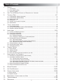
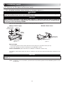
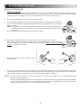
Installer Manual VENTILATION SYSTEMS VB0065 vänEE Canadian Model Numbers Broan U.S.A. Model Numbers 1001 ERV HRV100H 1001 HRV HRV200H 2001 ERV ERV100HC 2001 HRV* ERV200HC * This product earned the ENERGY STAR® by meeting strict energy efficiency guidelines set by Natural Resources Canada and the US EPA. It meets ENERGY STAR requirements only when used in Canada. 03119 rev. 07 Table of Contents 1. SERVICE ..................................................................................................................................3 1.1 3-D Drawing ................................................................................................................................................3 1.2 Parts Ordering Chart ..................................................................................................................................4 1.3 Technical Support........................................................................................................................................4 2. 3. UNIT TYPE & DEFROST SETTING VS GEOGRAPHICAL LOCATION ....................................................5 TECHNICAL DATA ....................................................................................................................6-7 3.1 3.2 3.3 3.4 3.5 3.6 4. Air Distribution (Normal Operation) ............................................................................................................6 Air Distribution (Defrost Mode)....................................................................................................................6 Defrost cycle table ......................................................................................................................................6 Dimensions..................................................................................................................................................7 Controls and Furnace Link Option ..............................................................................................................7 Specifications ..............................................................................................................................................7 TYPICAL INSTALLATIONS ..............................................................................................................8 4.1 Fully Ducted System ..................................................................................................................................8 4.2 Exhaust Ducted System (Source Point Ventilation) ....................................................................................8 4.3 Simplified (Volume Ventilation) ....................................................................................................................8 5. INSTALLATION ......................................................................................................................9-14 5.1 Locating and Mounting the Unit ..................................................................................................................9 5.2 Planning of the Ductwork ............................................................................................................................9 5.3 Calculating the Duct Size ..........................................................................................................................10 5.3.1 Example Calculation ......................................................................................................................10 5.3.2 Example of a Design for a Fully Ducted System ............................................................................10 5.4 Installing the Ductwork and Registers ......................................................................................................11 5.4.1 Fully Ducted System ......................................................................................................................11 5.4.2 Exhaust Ducted System (Source Point Ventilation) ........................................................................11 5.4.3 Simplified Installation (Volume Ventilation) ....................................................................................12 5.5 Connecting Duct to the Unit ......................................................................................................................13 5.6 Installing the Exterior Hoods ....................................................................................................................14 5.7 Connecting the Drain ................................................................................................................................14 6. CONTROL DEVICES ............................................................................................................15-16 6.1 6.2 6.3 6.4 7. Main Controls ............................................................................................................................................15 Optional Controls ......................................................................................................................................16 Other Features ..........................................................................................................................................16 Main and Optional Controls Available for your Unit ..................................................................................16 INSTALLATION OF THE CONTROLS ........................................................................................17-20 7.1 Dimensions and Specifications (Main Controls) ......................................................................................17 7.2 Installation of the Main Control ............................................................................................................17-19 7.2.1 Platinum Main Control Installation ..................................................................................................17 7.2.2 Deco-Touch Main Control Installation ............................................................................................18 7.2.3 Dehumidistat, DH100W, VT1W and VT2W Main Control Installation ............................................18 7.2.4 Main Control Electrical Connection ................................................................................................19 7.3 Electrical Connection to Optional Controls ..............................................................................................19 7.4 Electrical Connection to the Furnace ........................................................................................................20 8. 9. 10. WIRING DIAGRAMS ............................................................................................................21-22 AIR FLOW BALANCING ........................................................................................................23-24 OVERALL VERIFICATION ......................................................................................................25-26 10.1 Main Controls ............................................................................................................................................25 10.2 Optional Control ........................................................................................................................................26 11. 12. 13. MAINTENANCE / INSTRUCTIONS FOR USER ................................................................................26 TROUBLESHOOTING ............................................................................................................27-28 REFERENCES ..........................................................................................................................28 2 About this Manual This manual uses the following symbols to emphasize particular information: ! WARNING Identifies an instruction which, if not followed, might cause serious personal injuries including possibility of death. CAUTION Denotes an instruction which, if not followed, may severely damage the unit and/or its components. NOTE: Indicates supplementary information needed to fully complete an instruction. 1. Service 18 19 20 15 16 26 23 13 14 11 10 3 VL0016 7 8 5 4 3 1 6 2 9 12 ASSEMBLY (REAR VIEW) 25 21 17 22 24 3 23 3-D DRAWING DAMPER 1.1 1. Service (cont’d) 1.2 PARTS ORDERING CHART No. Description 1 2 3 4 5 6 7 8 9 10 11 12 13 14 15 16 17 18 19 20 21 22 23 24 25 26 Double collar port no. 2 Wing nut no. 10-32 Balancing double collar port Inlet ring Top wheel Electronic board V99 Motor assembly Bottom wheel Square balancing damper Door latches (latch) Drain connector Drain gasket 0,625” D Washer 5/8” ID x 1” OD Nut 5/8-18 Recovery core Door assembly Door latches (keeper) Hinge assembly Filter Switch E69 10A Damper assembly no. 2 Plastic balancing damper Damper rod Double collar port no. 5 Damper no. 1 Damper actuator assembly 1001 HRV 00866 00874 02256 12913 14307 13507 13504 02015 12645 00886 02418 02419 03117 02420 03132 12644 00887 00672 03096 01825 12643 02253 12620 02021 12459 03124 1001 ERV 00866 00874 02256 12913 03093 13507 13555 02015 12645 00886 02418 02419 03117 02420 03136 12644 00887 00672 03096 01825 12643 02253 12620 02021 12459 03124 2001 HRV 00866 00874 02256 12913 14308 13507 13556 03093 12645 00886 02418 02419 03117 02420 03133 12644 00887 00672 03097 01825 12649 02253 12620 02021 12459 03124 2001 ERV 00866 00874 02256 12913 03093 13507 13506 03093 12645 00886 02418 02419 03117 02420 03137 12644 00887 00672 03097 01825 12649 02253 12620 02021 12459 03124 HRV 100H 00866 00874 02256 12913 14307 13508 13504 02015 12645 00886 02418 02419 03117 02420 03134 12648 00887 00672 03096 01825 12643 02253 12620 02021 12459 03124 ERV 100HC 00866 00874 02256 12913 03093 13507 13555 02015 12645 00886 02418 02419 03117 02420 03136 12648 00887 00672 03096 01825 12643 02253 12620 02021 12459 03124 HRV 200H 00866 00874 02256 12913 14308 13508 13505 03093 12645 00886 02418 02419 03117 02420 03135 12648 00887 00672 03097 01825 12649 02253 12620 02021 12459 03124 ERV 200HC 00866 00874 02256 12913 03093 13507 13506 03093 12645 00886 02418 02419 03117 02420 03137 12648 00887 00672 03097 01825 12649 02253 12620 02021 12459 03124 Please take note that parts not listed are not available; those parts require assembly knowledge that only manufacturer can guarantee. REPLACEMENT PARTS AND REPAIR In order to ensure your ventilation unit remains in good working condition, you must use the manufacturer genuine replacement parts only. The manufacturer genuine replacement parts are specially designed for each unit and are manufactured to comply with all the applicable certification standards and maintain a high standard of safety. Any third party replacement part used may cause serious damage and drastically reduce the performance level of your unit, which will result in premature failing. Also, the manufacturer recommends to contact a certified service depot for all replacement parts and repairs. TO ORDER PARTS: Contact your local distributor 1.3 TECHNICAL SUPPORT (FOR ASSISTANCE) For assistance, call on week days, 8:30 AM to 5:00 PM (Eastern Standard Time). Technical Support Department Canada: Tel: 1-888-908-2633 (for distributors only) U.S.A.: Tel: 1-800-637-1453 NOTE: Do not call these numbers for ordering parts. 4 5 JUNEAU • Extended Defrost setting not required (factory defrost strategy pre-set). • MODELS: 1001 HRV, 2001 HRV, HRV100H, HRV200H ZONE B (HRVs only) SALEM OLYMPIA HAY RIVER PHOENIX REGINA SANTA FE AUSTIN • ERV MODELS: 1001 ERV, 2001 ERV, ERV100H, ERV200H. ZONE D (ERVs recommended) • HRV MODELS: 1001 HRV, 2001 HRV, HRV100H, HRV200H. • ERV MODELS: 1001 ERV, 2001 ERV, ERV100HC, ERV200HC. see ZONE C SELECTION CHART beside BATON ROUGE ATLANTA OTTAWA NORTH BAY COLUMBIA RALEIGH WASHINGTON HARTFORD MONTRÉAL and / or (condensation) Important excess moisture problem and / or Excess moisture problem Indoor air quality problem HALIFAX SYMPTOM BOSTON ST-JOHN ST JOHN'S ERV ERV HRV SOLUTION GOOSE BAY CHARLOTTETOWN BATHURST GASPÉ SEPT-ILES LABRADOR CITY MATANE QUEBEC CHICOUTIMI VAL-DOR HARRISBURG COLUMBUS NASHVILLE INDIANAPOLIS DETROIT TORONTO SUDBURY TIMMINS CHIBOUGAMAU ZONE C SELECTION CHART OKLAHOMA CITY SPRINGFIELD DES MOINES MADISON ST. PAUL SAULT STE MARIE ZONE B WINNIPEG TOPEKA BISMARCK ZONE D DENVER ZONE C SALT LAKE CITY HELENA LETHBRIDGE SASKATOON ZONE A ZONE C (HRV or ERV according to your client’s particular problems) RENO BOISE PENTICTON CALGARY PRINCE ALBERT FORT MCMURRAY FORT SMITH EDMONTON GRANDE PRAIRIE KAMLOOPS JASPER SACRAMENTO VICTORIA Prince Rupert WHITEHORSE • Set Extended Defrost according to section 7.2.3, point 4. • MODELS: 1001 HRV, 2001 HRV, HRV100H, HRV200H. ZONE A (HRVs only) VN0002 ANCHORAGE YELLOWKNIFE 2. Unit Type and Defrost Setting vs Geographical Location 3. Technical Data 3.1 AIR DISTRIBUTION (NORMAL OPERATION) STALE AIR FRESH AIR TO OUTSIDE FROM OUTSIDE FRESH STALE AIR TO BUILDING BUILDING VF0013 3.2 AIR DISTRIBUTION (DEFROST MODE) FRESH STALE AIR TO BUILDING AIR FROM VF0020 3.3 AIR FROM BUILDING DEFROST CYCLE TABLE OUTSIDE TEMPERATURE DEFROST CYCLES Celcius (°C) Fahrenheits (°F) Defrosting (min.) -5 -15 -27 23 5 -17 NOTE: THE EXTENDED DEFROST CYCLE Operation time (min.) Defrosting (min.) between each defrost cycle 6 6 6 32 32 20 10 10 10 Operation time (min.) between each defrost cycle 30 20 15 UNIT PERFORMANCE CHARTS ARE LISTED ON THEIR OWN SPECIFICATION SHEETS. TO ACCESS THOSE DOCUMENTS, VISIT: WWW.VANEE-VENTILATION.COM (CANADIAN UNITS) OR WWW.BROAN.COM 6 (U.S.A. UNITS). 3. Technical Data (cont’d) 3.4 DIMENSIONS 6" (152mm) Models numbers • 1001 ERV • 1001 HRV • HRV100H • ERV100HC 20" (508mm) 2½" (63mm) VK0040A Models numbers • 2001 ERV • 2001 HRV • HRV200H • ERV200HC 6" (152mm) 30¼" (768mm) CONTROLS AND 19" (483mm) 20" (508mm) 2½" (63mm) VK0039A 3.5 13¾" (349mm) 30¼" (768mm) FURNACE LINK OPTION Main controls: Optional controls: • Platinum (Canada only) • 20-minute push-button (for HRV100H and • Furnace interlock HRV200H models only) (use with forced air systems) • 20/40/60-minute push-button • Deco-Touch (Canada only) • VT1W (U.S.A.) • VT2W (U.S.A. only) Link option: (for all other models) • 60-minute crank timer • Dehumidistat 3.6 SPECIFICATIONS MODEL NUMBERS 1001 ERV, 1001 HRV, HRV100H, ERV100HC 2001 ERV, 2001 HRV, HRV200H, ERV200HC Weight 65 lb (30 kg) 73 lb (33 kg) Port diameter 6” (152 mm) 6” (152 mm) Drain diameter 1/2” (12 mm) 1/2” (12 mm) Installation - Chains, spring and hooks (provided with U.S.A. units) - Straps and washers (provided with Canadian units) Motor Speed High and low speeds factory set (optional increased low speed - BLUE wire) Electrical Supply 120 V, 60 Hz 120 V, 60 Hz Power consumption 150 watts 225 watts 7 4. Typical Installation There are three (3) common installation methods. 4.1 FULLY DUCTED SYSTEM (Primarily for homes with radiant hot water or electric baseboard heating. See figure 1.) Moist, stale air is exhausted from the high humidity areas in the home, such as bathrooms, kitchen and laundry room. Fresh air is supplied to bedrooms and principal living areas. If required, bathroom fans and a range hood may be used to better exhaust stale air. Homes with more than one level require at least one exhaust register at the highest level. SEE 5.4.1 Figure 1 FOR DETAILS VH0024 4.2 EXHAUST DUCTED SYSTEM (SOURCE POINT VENTILATION) (For homes with forced air heating. See figure 2.) Moist, stale air is exhausted from the high humidity areas in the home, such as bathrooms, kitchen and laundry room. Fresh air is supplied to the cold air return or the supply duct of the furnace. If required, bathroom fans and a range hood may be used to better exhaust stale air. Homes with more than one level require at least one exhaust register at the highest level. NOTE: For this type of installation, it is not essential that the furnace blower runs when the unit is in operation, but we recommend it. SEE 5.4.2 VH0025 4.2 Figure 2 FOR DETAILS SIMPLIFIED (VOLUME VENTILATION) (For homes with forced air heating. See figure 3 or 4.) Fresh air and exhaust air flow through the furnace ducts which simplifies the installation. The use of bathroom fans and a range hood is suggested to better exhaust stale air. NOTE: For the installation type shown in figure 4, furnace blower should be running when the unit is in operation. OR SEE 5.4.3 Figure 3 SEE 5.4.3 Figure 4 FOR DETAILS VH0026 VH0027 8 FOR DETAILS 5. Installation ! WARNING When applicable local regulations comprises more restrictive installation and/or certification requirements, the aforementioned requirements prevail on those of this document and the installer agrees to conform to these at his own expenses. ! WARNING When performing installation, servicing or cleaning the unit, it is recommended to wear safety glasses and gloves. INSPECT THE CONTENTS • • • • 5.1 OF THE BOX Inspect the exterior of the unit for shipping damage. Ensure that there is no damage to the door, door latches, door hinges, dampers, duct collars, cabinet, etc. Inspect the interior of the unit for damage. Ensure that the fan motor assembly, recovery core, insulation, dampers, damper actuator and drain pan are all intact. If the unit was damaged during shipping, contact your local distributor. (Claim must be made within 24 hours after delivery.) Use checklist included with the unit to ensure that no parts are missing. LOCATING AND MOUNTING THE UNIT Choose an appropriate location for the unit: • Within an area of the house where the temperature is kept above 10°C / 50°F and below 40°C/104°F. • Away from living areas (dining room, living room, bedroom), if possible. • So as to provide easy access to the interior cabinet for every three months and annual maintenance, and to the control panel on the right hand side of the unit. • Close to an exterior wall, so as to limit the length of the insulated flexible duct to and from the unit. • Close to a drain. If no drain is close by, use a pail to collect run-off. • Away from hot chimneys, electrical panel and other fire hazards. • Allow for a power source (110 V standard outlet). VD0064 Figure 6 CAUTION Make sure the unit is level. For vänEE Canadian models 1001 VRE, 1001 VRC, 2001 VRE and 2001 VRC, hang the unit to ceiling joists with washers and 4 straps (included) (see figure 7 beside). For Broan U.S.A. models HRV100H, HRV200H, ERV100HC, and ERV200HC, hang the unit to ceiling joists with the 4 chains, springs and hooks (included) (see figure 7 beside). VD0212 VÄNEE CANADIAN MODELS 1001 VRE, 1001 VRC, 2001 VRE AND 2001 VRC BROAN U.S.A. MODELS HRV100H, HRV200H, ERV100HC AND ERV200HC Figure 7 5.2 a) b) c) d) e) PLANNING OF THE DUCTWORK Follow the instructions in Section 5.3 next page to determine the appropriate duct diameters for your system. Keep it simple. Plan for a minimum number of bends and joints. Keep the length of insulated duct to a minimum. Do not use wall cavities as ducts. Do not use branch lines smaller than 4” (102 mm) Ø. Do not ventilate crawl spaces or cold rooms. Do not attempt to recover the exhaust air from a dryer or a range hood. This would cause clogging of the recovery module. Use sheet metal for the kitchen exhaust duct. Be sure to plan for at least one exhaust register on the highest lived-in level of the house if it has 2 floors or more. 9 5. Installation (cont’d) 5.3 CALCULATING THE DUCT SIZE Use the table below to ensure that the ducts you intend to install will be carrying air flows at or under the recommended values. Avoid installing ducts that will have to carry air flows near the maximum values and never install a duct if its air flow exceeds the maximum value. DUCTS RECOMMANDED AIR FLOW DIAMETER 4” (102 5” (127 6” (152 7” (178 8” (203 mm) mm) mm) mm) mm) 40 cfm 75 cfm 120 cfm 185 cfm 260 cfm 19 l/s 35 l/s 57 l/s 87 l/s 123 l/s END MAXIMUM AIR FLOW 68 m³/h 127 m³/h 204 m³/h 314 m³/h 442 m³/h 60 cfm 110 cfm 180 cfm 270 cfm 380 cfm 28 l/s 52 l/s 85 l/s 127 l/s 179 l/s BRANCHES 102 187 306 459 645 5”Ø 70 CFM m³/h m³/h m³/h m³/h m³/h MAIN BRANCH 6”Ø 140 CFM 140 NOTE: Examples 5.3.1 and 5.3.2 use imperial measures. The same calculation applies to metric measures. 5.3.1 CFM VI0003 Figure 8 Example of calculation: Problem: My installation requires two exhaust registers (one for the kitchen, one for the bathroom). I will connect these registers to a main duct which will connect to the unit (high speed performance value of 140 cfm). What size of duct should I use for the main exhaust duct and for the two end branches leading to the registers? (See figure 8.) Solution: Simplified method. (For a more detailed method of calculating duct size refer to the ASHRAE or HRAI HANDBOOK). Main duct: Table above indicates a 6” Ø duct: Recommended air flow: 120 cfm; maximum air flow: 180 cfm. The high speed air flow of 140 cfm is close enough to the recommended value (120) and far enough away from the maximum value (180). Therefore a 6” Ø duct or larger is an appropriate choice for the main exhaust duct. End branches: Each end branch will have to transport an air flow of 70 cfm (140 divided by 2). Table above indicates a 5” Ø duct: Recommended air flow: 75 cfm; maximum air flow: 110 cfm. The high speed air flow of 70 cfm is close enough to the recommended value (75) and far enough away from the maximum value (110). Therefore a 5” Ø duct or larger is an appropriate choice for the 2 end branches. NOTE: 5.3.2 A 4”Ø duct would have been too small because the maximum acceptable value for a 4”Ø duct is 60 cfm. Example of a design for a fully ducted system for a unit having a high speed performance of 222 cfm (See figure 9). 4” 4” 4” Ø 42 5” 5” Ø 64 CFM 5” Ø 65 CFM 4” Ø 42 CFM CFM 4” 6” Ø 96 4” 6” Ø 84 6” 6” Ø 129 CFM 6” 6” 7” 6” 7” 6” Ø 93 CFM CFM CFM 6” Ø 138 7” Ø 222 VI0004 7” Ø 222 CFM Figure 9 10 CFM CFM 5. Installation (cont’d) 5.4 INSTALLING THE DUCTWORK AND REGISTERS ! WARNING Never install a stale air exhaust register in a room where a combustion device is, such as a gas furnace, a gas water heater or a fireplace. CAUTION The ductwork is intended to be installed in compliance with all applicable codes. 5.4.1 Fully Ducted System (as illustrated in Section 4.1) Stale air exhaust ductwork: • • • • Install registers in areas where contaminants are produced: kitchen, bathrooms, laundry room, etc. Install registers 6 to 12 inches (152 to 305 mm) from the ceiling on an interior wall OR install them in the ceiling. Install the kitchen register at least 4 feet (1.2 m) from the range top. If possible, measure the velocity of the air flowing through the registers. If the velocity is higher than 400 ft/min. (122 m/min), then the register type is too small. Replace with a larger one. Fresh air distribution ductwork: • • • 5.4.2 Install registers in bedrooms, dining room, living room and basement. Install registers either in the ceiling or high on the walls with air flow directed towards the ceiling. (The cooler air will then cross the upper part of the room, and mix with room air before descending to occupant level.) If a register must be floor installed, direct the air flow up the wall. Exhaust Ducted System (Source Point Ventilation) (as illustrated in Section 4.2) Stale air exhaust ductwork: (Same as for Fully Ducted System, described on Section 5.4.1) Fresh air distribution: ! WARNING When performing duct connection to the furnace, installation must be done in accordance with all applicable codes and standards. Please refer to your local building code. CAUTION When performing connection to the furnace supply duct, this duct must be sized to support the additional airflow produced by the HRV/ERV. Also, use a metal duct with a backdraft damper to prevent the risk of overheating the HRV/ERV. There are two methods for connecting the unit to the furnace: METAL DUCT WITH Method 1: Supply side connection BACKDRAFT DAMPER • • • • Cut an opening into the furnace supply duct at least 18 inches (0.5 m) from the furnace. Connect this opening to the fresh air distribution port of the HRV/ERV (use metal duct, see figure 10). Make sure that the HRV/ERV duct forms an elbow inside the furnace ductwork. If desired, interlock (synchronize) the furnace blower operation with the HRV/ERV operation. (See Section 7.4). MINIMUM 18” (0.5 M) VD0040 Figure 10 Method 2: Return side connection • Cut an opening into the furnace return duct not less than 10 feet (3.1 m) from the furnace (A + B). • Connect this opening to the fresh air distribution port of the HRV/ERV (see figure 11). NOTE: For Method 2, it is not essential that the furnace blower runs when the HRV/ERV is in operation, but we recommend it. If desired, synchronize the furnace blower operation (see Section 7.4). A A + B = NOT LESS THAN 10’ (3.1 M) B VD0041 Figure 11 11 5. Installation (cont’d) 5.4 INSTALLING THE DUCTWORK 5.4.3 AND REGISTERS (cont’d) Simplified installation (Volume Ventilation) (as illustrated in Section 4.3) ! WARNING When performing duct connection to the furnace, installation must be done in accordance with all applicable codes and standards. Please refer to your local building code. CAUTION When performing connection to the furnace ducts (Method 1), these ducts must be sized to support the additional airflow produced by the HRV/ERV. Also, the supply duct must be a metal duct with a backdraft damper to prevent the risk of overheating HRV/ERV. There are two methods (figures 12 and 13) for connecting the unit to the furnace: Method 1: Return-supply Method 2: Return-return METAL DUCT WITH BACKDRAFT DAMPER MINIMUM 18” (0.5 M) A A B A + B = NOT LESS THAN 10’ (3.1 M) B VD0042 A + B = NOT LESS THAN 10’ (3.1 M) VD0043 MINIMUM 3’ (0.9 M) Figure 13 Figure 12 Stale air intake: • Cut an opening into the furnace return duct not less than 10 feet (3.1 m) from the furnace (A + B). • Connect this opening to the stale air intake port on the HRV/ERV as shown . Fresh air distribution: (Same instructions as for Method 1 or Method 2, Section 5.4.2). For method 2 (return-return) make sure there is a distance of at least 3 feet (0.9 m) between both connections to the furnace. CAUTION If using Method 2, make sure the furnace blower operation is synchronized with the HRV/ERV operation! See Section 7.4. NOTE: For Method 1, it is not essential to synchronize the furnace blower operation with the HRV/ERV operation, but we recommend it. 12 5. Installation (cont’d) 5.5 CONNECTING DUCTS TO THE UNIT Insulated flexible duct Use the following procedure for connecting the insulated flexible duct to the ports on the unit (exhaust to outside and fresh air from outside). a) Pull back the insulation to expose the flexible duct. b) Connect the interior flexible duct to the port using a duct tie. c) Carefully seal the connection with duct tape. d) Pull the insulation over the joint and tuck it between the inner and outer rings of the double collar. e) Pull the vapor barrier over the insulation and over the outer ring of the double collar. f) Apply duct tape to the joint making an airtight seal. Avoid compressing the insulation when you pull the tape tightly around the joint. Compressed insulation loses its R value and causes water dripping due to condensation on the exterior surface of the duct. CAUTION Make sure that the vapor barrier on the insulated ducts does not tear during installation to avoid condensation within the duct. a) b) VJ0001 VJ0002 c) d), e) f) VJ0004 VJ0005 VJ0003 Rigid duct: Use duct tape to connect the rigid ducts to the ports. CAUTION Do not use screws to connect rigid ducts to the ports. Make sure that the 2 balancing dampers are left in a fully open position before connecting the ducts to these ports (fresh air distribution port and stale air exhaust port as shown on figure 14). VJ0009 Figure 14 13 5. Installation (cont’d) 5.6 INSTALLING THE EXTERIOR HOODS CAUTION All models require an exhaust hood with a backdraft damper. This damper closes when the unit is off and prevents unwanted cold air from entering the house. 6”Ø (152 MM) Choose an appropriate location for installing the exterior hoods: • At a minimum distance of 6 feet (1.8 m) between the hoods to avoid cross-contamination • At a minimum distance of 18 inches (457 mm) from the ground INTAKE HOOD EXHAUST 18” (457 MM) HOOD 6’ (1.8 M) ! WARNING Make sure the intake hood is at least 6 feet (1.8 m) away from any of the following: • Dryer exhaust, high efficiency furnace vent, central vacuum vent • Gas meter exhaust, gas barbecue-grill • Any exhaust from a combustion source • Garbage bin and any other source of contamination 18” (457 MM) 6’ (1.8 M) OPTIONAL 18” (457 DUCT LOCATION TAPE MM) AND DUCT TIE CAULKING Refer to figure 15 for connecting the insulated duct to the hoods. Place the “FRESH AIR INTAKE” sticker, provided in the installation kit, on corresponding hood. An “Anti-Gust Intake Hood” should be installed in regions where a lot of snow is expected to fall. Figure 15 VD0028 5.7 CONNECTING THE DRAIN VO0003 1 Attach the 2 plastic drain fittings to the unit using the gaskets, washers and nuts as shown. TIE-WRAP ± 12" (± 305 mm) ± 12" (± 305 mm) 2 VO0005A Cut 2 sections of plastic tubing, about 12” (305 mm) long and attach them to each drain fitting. Join the 2 short sections to the “T” junction and main tube as shown. If using a pail to collect water, locate the tube end approximately 1” from the top of the pail in order to prevent water from being drawn back up into the unit. ± 1” VD0231A 14 VO0011 TO DRAIN 3 Make a water trap loop in the tube to prevent the unit from drawing unpleasant odors from the drain source. Make sure this loop is located BELOW the “T” as shown. This will prevent water from being drawn back up into the unit in case of negative pressure. Run the tube to the floor drain or to an alternative drain pipe or pail. Be sure there is a slight slope for the run-off. 6. Control Devices 6.1 MAIN CONTROLS CAUTION All models require a main control. Platinum model (Canada) VT1W model (U.S.A.) Deco-Touch model (Canada) VT2W model (U.S.A.) CONDENSATION CONTROL CONDENSATION CONTROL E MM SU R R E MM SU -20°C -4°F CO M F OR T Z ON E -5°C 23°F -20°C -4°F 5°C 41°F CO M F OR T Z ON E -5°C 23°F 5°C 41°F AIR SUPPLY CONTROL CONDENSATION CONTROL MAXIMUM SPEED OFF AIR EXCHANGE IN PROGRESS AIR SUPPLY CONTROL MIN. MODE PREF SET SMART AIR EXCHANGE MIN. MAX. 20 MIN. ON MAX. CONTINUOUS VC0117 VC0104 40 MIN. OFF INTERMITTENT VC0028 VC0027 Dehumidistat 3-position switch Designed primarily for use with our low price HRV (Heat Recovery Ventilator) units, the dehumidistat helps control indoor maximum humidity level during fall, winter and spring. This control should not be installed in a house already equipped with other main controls (except the 3-position switch). You will find a relative humidity % scale instead of a temperature scale meant to reduce the window condensation problems. Some model may come with a 3-position mounted switch on the electrical box on the exterior lower right front side. It is basically an airflow control that gives the customer the choice between the low and high speed or the OFF (REMOTE) position. This OFF (REMOTE) position does not deactivate the optional controls. U.S.A. MODELS DH100W CANADIAN MODELS VT1W VT2W DEHUMIDISTAT OFF Position X X Intermittent exchange (TBI) 20 ON - 40 OFF X PLATINUM X X X Intermittent exchange OR OFF (ON - OFF or ON - Recirculation) MODES DECOTOUCH X X Low speed continuous exchange X X X X High speed continuous exchange X X X X SMART (entirely automatic mode optimizing ventilation) X Program (programs the desired ventilation according to the period of the day) X Humidity control (Relative humidity scale %) TYPES DETECTOR Recirculation (manual mode performing air recirculation inside the house) X X Outdoor temperature X Indoor relative humidity X X Air exchange indicator Condensation/Polluant control max speed indicator X X X X X X X X X X Maintenance indicator Day and hour indicators SWITCHES X X Indoor condensation control (Temperature scale) Mode indicator INDICATORS X X Sliding button X Push button X 15 X X 6. Control Devices (cont’d) 6.2 OPTIONAL CONTROLS LIGHTED PUSH-BUTTON REMOTE 20-MINUTE SWITCH: This remote illuminated switch is typically installed in bathrooms, kitchen and laundry room to provide 20 minutes of high speed ventilation at the push of a button. The switch is supplied and mounted on a white single gang wall plate. This push-button is available only for HRV100H and HRV200H units. 20/40/60-MINUTE PUSH-BUTTON TIMER: This remote illuminated switch is typically installed in bathrooms, kitchen and laundry room to provide 20, 40 or 60 minutes of high speed ventilation at the push of a button. The switch is supplied and mounted on a white single gang wall plate. This push-button is not available for HRV100H and HRV200H units. MECHANICAL TIMER This timer allows up to 60 minutes of high speed operation to be selected from a remote location. 6.3 OTHER FEATURES FURNACE INTERLOCK (for forced air heating system) The furnace fan can be interlocked so that it will run simultaneously with the ERV or HRV to ensure proper distribution of fresh air throughout the house (see table section 6.4, to see if it is available on your unit). PERMANENT MEMORY Our electronic controls have a default memory feature in the event of a power outage. Even the date of the last service reminder is maintained as a convenience to the homeowner. NOTE: For Platinum control only, if the power failure duration is more than 4 hours, the day and hour settings must be reprogrammed. CONTROL UPGRADES All controls can be used on any ERV, so a VT1W control can be upgraded to a VT2W in the future (see table in Section 6.4 below for control availability according to the units). 6.4 MAIN AND OPTIONAL CONTROLS AVAILABLE FOR YOUR UNIT MAIN CONTROLS MODEL NUMBER DH100W DEHUMIDISTAT VT1W 1001 ERV X ERV100HC X VT2W DECO-TOUCH PLATINUM X X 1001 HRV X X X 2001 ERV X X X ERV200HC X 2001 HRV X X X HRV100H / HRV200H X X X X OPTIONAL CONTROLS MODEL NUMBER 20/40/60-MINUTE 20-MINUTE PUSH-BUTTON TIMER PUSH-BUTTON TIMER 60-MINUTE CRANK TIMER FURNACE INTERLOCK 1001 ERV X X INTEGRATED ERV100HC X X INTEGRATED 1001 HRV X X INTEGRATED 2001 ERV X X INTEGRATED ERV200HC X X INTEGRATED 2001 HRV X X INTEGRATED HRV100H / HRV200H X X 16 OPTIONAL KIT PART NO.12658 7. Installation of the Controls 7.1 DIMENSIONS AND SPECIFICATIONS (MAIN CONTROLS) DEHUMIDISTAT, DH100W, VT1W, VT2W VOLTAGE: PLATINUM AND VOLTAGE: 12 volts DC DECO-TOUCH 1³/8" (35 mm) 1" (26 mm) 5" (127 mm) 2¾" (70 mm) 4¼" (107 mm) 4½" (114 mm) 4" (102 mm) 5" (127 mm) VC0105A VC0016A VC0118A FRONT VIEW 7.2 VOLTAGE: 12 volts DC 12 volts DC INSTALLATION OF THE FRONT VIEW SIDE VIEW SIDE VIEW MAIN CONTROL ! WARNING Always disconnect the unit before making any connections. Failure in disconnecting power could result in electric shock or damage of the control or electronic module inside the unit. CAUTION Failure to comply with the following can cause erratic operation of the unit: • Never install more than one optional control per unit. • Keep control low voltage wiring at least 1 foot (305 mm) away from motors, lighting ballast, light dimming circuit and power distribution panel. Do not route control wiring alongside house power wiring. • Ensure the wires are securely connected. 7.2.1 Platinum Main Control Installation 1. Route the cable from the unit to a convenient location for the control. 2. Detach the front module from the mounting plate by pulling the bottom part. YELLOW 4. Splice back the end of the cable to access the 4 wires. Strip the end of each wire. Connect each wire to its corresponding terminal on the back of the front module: YELLOW wire to “Y”, RED wire to “R”, GREEN wire to “G” and BLACK wire to “B”. RED WIRE GREEN WIRE BLACK VE0173 VC0102 WIRE WIRE CAUTION Be careful not to pinch wires when reinstalling the front module on its back plate. 3. Run the cable (4 wires) through the central opening of the mounting plate and mount this plate to the wall using screws (not included). If needed, use wall anchors (not included). 5. Reinstall the front module over the back plate. VC0103 17 7. Installation of the Controls (cont’d) 7.2 INSTALLATION 7.2.2 OF THE MAIN CONTROL (CONT’D) Deco-Touch Main Control Installation 4. Strip the end of the cable to access the 4 wires. Strip the end of each wire. Using a small flat blade screwdriver, connect each wire to its corresponding terminal on the back of the wall control: YELLOW wire to “Y”, RED wire to “R”, GREEN wire to “G” and BLACK wire to “B”. 1. Cut a 2 /8” x 1 ³/8” hole in wall at a convenient location for the wall control. Route the cable from the unit to this hole. 7 NOTE: Dimensions shown are for an installation without wall box. Y R G B VE0243 Ø 3/16”, typ. 2. Temporarily place the switch over the hole and mark both mounting screw hole positions. 5. Mount the wall control to the wall. 3. Remove the switch, drill both screw holes (Ø 3/16”) in wall and insert wall anchors (included). VC0116A 7.2.3 VC0115 Dehumidistat, DH100W, VT1W, and VT2W Main Controls Installation 1- Determine the location of the control. The control must be installed in a central location on the main floor. Typical locations for these controls are kitchen, main hallways and family room. 2- Remove the button(s) and the cover plate of the control. VC0026 Dehumidistat or VT2W VT1W 2" (5 cm) 3- Install the control 60 inches (1.5 m) from the floor and leave a free space of at least 2 inches (5 cm) to the right of the control to allow user to slide out the control instructions (see figure beside). 60" (1.5 m) Use the template provided in the control box to position the wire hole and the screw holes. Use the screws and the plastic anchors provided in the installation kit to secure the control. VD0025A 18 7. Installation of the Controls (cont’d) INSTALLATION 7.2.3 4- OF THE MAIN CONTROL (CONT’D) Dehumidistat, DH100W, VT1W, and VT2W Main Controls Installation (cont’d) Connect the wires to the main control. (See figures beside) NOTE: For HRV100H and HRV200H only: To install VT1W, only connect GREEN and BLACK wires to main control. VT1W Y R GB AND VT2W VE0124 7.2 DEHUMIDISTAT VC0068 5- Make sure the instruction pull-out is in the occupant’s language. If not, turn it to the other side (see figure beside). 6- Reinstall the cover plate and the button(s). VC0061 7.2.4 Main Control Electrical Connection (All models) BVT2W / PLATINUM / DECO-TOUCH 1- Connect the wires to their corresponding position inside the electrical compartment. Make sure the connections of the unit and of the control correspond exactly. (See figure beside.) VT1W DEHUMIDISTAT Proper switch Position G B G B Y R G B VENTILATION REMOTE ARRÊT HIGH SPEED HAUTE VITESSE F F I OCOL Y R G B F F I OCOL Y F F I OCOL Y R G B VE0038A LOW SPEED BASSE VITESSE R G B SWITCH 2- Connect the optional control (if applicable) by referring to Section 7.3. 3- Do the appropriate connection to the furnace (if applicable) by referring to Section 7.4. 4- NOTE: If the unit is installed in a cold region (Zone A, as defined in Section 2), set up “extended defrost” by removing jumper JU1F on the main circuit board inside the electrical compartment (see Section 8). 5- Plug in the unit and do the “overall verification” of the system as described in Section 10. 7.3 ELECTRICAL CONNECTION TO OPTIONAL CONTROLS MAIN PC BOARD 9 8 7 6 OL 5 OC 4 I 3 2 1 J3 J1 VE0164A 1 4 7 2 5 8 3 6 9 0L PUSH-BUTTON SWITCHES (HRV100H and HRV200H : 5 switches maximum) 19 0C I REAR VIEW 7. Installation of the Controls (cont’d) 7.4 ELECTRICAL CONNECTION TO THE FURNACE ! WARNING Never connect a 120-volt AC circuit to the terminals of the furnace interlock (standard wiring). Only use the low voltage class 2 circuit of the furnace blower control. For a furnace connected to cooling system: On some older thermostats, energizing the “R” and “G” terminals at the furnace has the effect of energizing “Y” at the thermostat and thereby turning on the cooling system. If you identify this type of thermostat, you must use the “alternate furnace interlock wiring”. An additional control relay will then have to be installed. NOTE: For HRV100H and HRV200H units, always use the “alternate furnace interlock wiring”. STANDARD FURNACE INTERLOCK WIRING W R G Y THERMOSTAT TERMINALS W 4 WIRES UNIT CONTROL CONNECTOR J3 2 WIRES (heating only) 9 8 7 6 5 4 3 2 1 FOUR WIRES TWO WIRES heating only ALTERNATE FURNACE INTERLOCK WIRING F F I OC OL Y R G B W W RR R G Y wiring nuts NC C YY Y FURNACE 24-VOLT TERMINAL BLOCK FURNACE 24-VOLT TERMINAL BLOCK TWO WIRES COOLING SYSTEM VE0009A VE0010A 20 4 77 2 5 8 3 6 9 GRAY RED G C 1 BROWN GREEN R G Unit Control Module 9-PIN AMP PLUG J1 THERMOSTAT TERMINAL NO COM BLUE *FURNACE INTERLOCK RELAY 2 WIRES COOLING SYSTEM *FURNACE INTERLOCK RELAY, PART NO. 12658 21 VE0037A ELECTRONIC ASSEMBLY T1 W BK 8 7 GY BK O R 7- SPECIFIED UL LISTED/CSA CERTIFIED LINE FUSE. LittelFuse (225 003), 2AG Fast-Acting Fuse, 224/225 Series. Rating: 3 A 6- The furnace fan circuit must be class 2 circuit only. NOTES 1- Controls available. See Section 7 (Low voltage only, 12VDC). 2- The factory set wiring for blower speed selection is high and low. Medium speed can be selected instead of low speed. Disconnect the RED wire from the motor RED tap and connect it to the motor BLUE tap. 3- If any of the original wire, as supplied, must be replaced, use the same or equivalent wire. 4- Use the factory supplied protective tubing. 5- The field wiring must comply with applicable codes, ordinances and regulations. R1 -t DEFROST TEMPERATURE SENSOR JU1 J4 J1 9 ABCDEFG 6 5 4 3 2 A1 2 1 1 2 3 1 4 6 F F I OCOLY R G B 7 9 NOTE 4 J3 Y NO BK BL BN G GY LINE BL DAMPER BL MOTOR M2 NEMA-15P 5-15 PLUG W1 BN BN C1 120V 60 Hz NO CONNECTION ORANGE RED WHITE YELLOW LOW VOLTAGE AND FIELD WIRE LINE VOLTAGE BK G W MAIN EARTHING POINT 2 1 NOTE 7 F1 NEUTRAL Y BL X2 M1 X1 GY GY 12 NEUTRAL O O 3 HIGH G G BL MEDIUM NC LOW R R (NOTE 2) FURNACE BLOWER NOTES 5, 6 OPTIONAL INTERLOCK COLOR CODE BLACK NC BLUE O BROWN R GREEN W GREY Y DOOR INTERLOCK SWITCH S1 COM BL OVERRIDE SWITCH OVERRIDE SWITCH OVERRIDE LED R BK Y NOTE 5 OPTIONAL WALL CONTROL WALL CONTROL NOTES 1, 5 WALL CONTROL WALL CONTROL Connection BK G R Y Models: 1001 ERV, 1001 HRV, 2001 ERV, 2001 HRV, ERV100HC, ERV200HC 120V 60Hz Logic S1 J1 9 A B C D E F G • • • • • • • • • • • • • • JU1 J3 1 K5 RELAY K2 RELAY J1 4 J1 6 2 1 NO OUT NO OUT NO OUT NO OUT 1 1 1 1 0 Exchange High Circulation Low Circulation High Defrost Cycle OFF 1 = Relay coil is energized 0 = Relay coil is de-energized 1 0 K1 Exchange Low Intermittent MODE FUNCTION TABLE 0 1 1 0 1 0 0 K2 CHANGE CHANGE CHANGE CHANGE CHANGE NO OUT 0 1 1 1 1 1 0 K4 NO OUT 0 0 0 0 1 1 0 MED M1 DAMPER MOTOR M2 HIGH FAN MOTOR LOW 6/32 23°F -5°C ALL 10/30 MODELS ALL MODELS K5 CHANGE RELAY OUT IN NC J1 8 J1 1 NEUTRAL J1 2 10/20 6/32 5°F -15°C 10/15 6/20 -17°F -27°C DEFROST TIME MODELS DEFROST/VENTILATION TYPES MINUTES FURNACE BLOWER INTERLOCK CLASS 2 CIRCUIT ONLY J3 2 ELECTRONIC ASSEMBLY K1 RELAY K4 RELAY J1 3 A1 JU1A JU1B JU1C JU1D JU1E JU1F JU1G JUMPERS TABLE VE0018A FROM MAIN 8. Wiring Diagrams Risk of electric shocks. Before performing any maintenance or servicing, always disconnect the unit from its power source. This product employs overload protection (fuse). A blown fuse indicates an overload or short-circuit situation. If the fuse blows, unplug the product from the outlet. Replace the fuse as per the servicing instructions (follow product marking for proper fuse rating) and check the product. If the replacement fuse blows, a short-circuit may be present and the product should be discarded or returned to an authorized service facility for examination and/or repair. ! WARNING 22 NOTES ELECTRONIC ASSEMBLY T1 W BK 8 7 GY BK O R 7- SPECIFIED UL LISTED/CSA CERTIFIED LINE FUSE. LittelFuse (225 003), 2AG Fast-Acting Fuse, 224/225 Series. Rating: 3 A 6- The furnace fan circuit must be class 2 circuit only. 6- The field wiring must comply with applicable codes, ordinances and regulations. 5 Field installed option: Use only factory supplied kit. 4- Use the factory supplied protective tubing. 3- If any of the original wire, as supplied, must be replaced, use the same or equivalent wire. Y GY BK BL BN G GY Connection NO BN Y BL BLACK BLUE BROWN GREEN GREY 2 1 M2 BL DAMPER BL MOTOR BN BN NEMA-15P 5-15 PLUG W1 NOTES 5, 6 120V 60 Hz C1 NO CONNECTION ORANGE RED WHITE YELLOW LOW VOLTAGE AND FIELD WIRE LINE VOLTAGE COLOR CODE NC O R W Y NOTE 7 BK G W MAIN EARTHING POINT X2 FAN FURNACE INTERLOCK KIT F1 NEUTRAL LINE M1 GY 12 GY NEUTRAL O 3 O HIGH G G NC BL MEDIUM LOW R R (NOTE 2) X1 OVERRIDE SWITCH NOTES 1, 6 OVERRIDE SWITCH OPTIONAL OVERRIDE LED SPDT SWITCH (ON-OFF-ON) S2 BK TO R = LOW SPEED EXCHANGE BK BK TO G = HIGH SPEED EXCHANGE NOTE 1 G NO CONNECTION = OFF R DOOR INTERLOCK SWITCH S1 COM BL 2- The factory set wiring for blower speed selection is high and low. Medium speed can be selected instead of low speed. Disconnect the RED wire from the motor RED tap and connect it to the motor BLUE tap. 1- Controls cannot be connected to J3. VE0039A R1 -t DEFROST TEMPERATURE SENSOR JU1 J4 J1 9 ABCDEFG 5 4 3 2 A1 2 1 1 2 3 1 4 6 F F ICOCOLY R G B 7 9 NOTE 4 J3 Models: HRV100H, HRV200H 120V 60Hz Logic S1 K5 RELAY K2 RELAY J1 9 A B C D E F G 2 1 ELECTRONIC ASSEMBLY K1 RELAY J1 4 J1 6 • • • • • • • • • • • • • • JU1 J1 3 A1 IN 0 0 OFF 1 = Relay coil is energized 0 = Relay coil is de-energized 1 1 1 1 0 1 0 0 K2 Circulation High 1 1 1 0 K1 RELAY Defrost Cycle Circulation Low Exchange High Exchange Low Intermitent MODE FUNCTION TABLE OUT OUT OUT OUT OUT OUT OUT OUT OUT OUT OUT 0 0 0 0 1 1 0 K5 IN IN JU1A JU1B JU1C JU1D JU1E JU1F JU1G JUMPERS TABLE VE0040A FROM MAIN M1 M2 J1 8 J1 1 23°F 5°F -5°C -15°C 10/15 6/20 -17°F -27°C DEFROST TIME DEFROST/VENTILATION MINUTES DAMPER MOTOR LOW FAN MOTOR HIGH MED HRV100H 6/32 6/32 HRV200H EXTENDED DEFROST 10/30 10/20 ALL TYPES MODELS TYPES NC NEUTRAL J1 2 8. Wiring Diagrams (cont’d) Risk of electric shocks. Before performing any maintenance or servicing, always disconnect the unit from its power source. This product employs overload protection (fuse). A blown fuse indicates an overload or short-circuit situation. If the fuse blows, unplug the product from the outlet. Replace the fuse as per the servicing instructions (follow product marking for proper fuse rating) and check the product. If the replacement fuse blows, a short-circuit may be present and the product should be discarded or returned to an authorized service facility for examination and/or repair. ! WARNING 9. Air Flow Balancing WHAT YOU NEED TO BALANCE THE UNIT LOW • A magnehelic gauge capable of measuring 0 to 0.25 inch of water (0 to 62.5 Pa) and 2 plastic tubes. Two ”Flow Measuring Stations” or two flow collars (the size will vary depending on the duct diameter). HIGH FLOW • LOW HIGH FLOW VP0006 VP0005 Flow collar Flow measuring station PRELIMINARY STAGES TO BALANCE THE UNIT • • • • Seal all the unit ductwork with tape. Close all windows and doors. Turn off all exhaust devices such as range hood, dryer and bathroom fans. Make sure all filters are clean (if it is not the first time you balance the unit). Make sure the balancing dampers are fully open (F and G in figure below). Choose appropriate locations for the 2 flow collars (or flow measuring stations), according to figure below: • On the exhaust air duct (first measuring location, A) • On the fresh air distribution duct (second measuring location, B • At least 36” away from the unit; at least 12” before or after a 90° elbow; at least 12” away from a register. OR A B 12” (304mm) 12” (304mm) 36” (914mm) 36” (914mm) F G VP0012A INSTALLATION • • OF FLOW COLLARS OR “FLOW MEASURING STATIONS” If you are using Flow Collars: Insert the flow collars in the duct at each location. Make sure their arrows are pointing in the direction of the airflow. Tape collars in place temporarily. If you are using “Flow Measuring Stations”: Cut a 1” (25.4 mm) diameter hole in the duct at each location. Insert the “Flow Measuring Stations”. Make sure their arrows are pointing in the direction of the airflow. Tape the “Flow Measuring Stations” in place temporarily. 23 9. Air Flow Balancing (cont’d) BALANCING PROCEDURE 1. Set the unit to high speed. Make sure that the furnace blower is ON if the installation is in any way connected to the ductwork of the cold air return. If not, leave furnace blower OFF. If the outside temperature is below 0°C / 32°F, make sure the unit is not running in defrost while balancing. (By waiting 10 minutes after plugging the unit in, you are assured that the unit is not in a defrost cycle.) 2. Place the magnehelic gauge on a level surface and adjust it to zero. 3. Connect tubing from gauge to flow collar (or “Flow Measuring Station”) in exhaust air stream at location A. Be sure to connect the tubes to their appropriate high/low fittings. If the gauge drops below zero, reverse the tubing connections. NOTE: It is suggested to start with the exhaust air flow reading because the exhaust has typically more restriction than the fresh air, especially in cases of fully ducted installations and exhaust ducted installation. Place the magnehelic gauge upright and level. Record the readings. LOW HIG H FLOW VP0003 4. Move tubing to FRESH air flow on the other side of the unit (location B) and note readings. Adjust the fresh air balancing damper F until the reading at B is approximately the same as the reading at A. If the reading at B is less than the reading at A, then go back and adjust the exhaust balancing damper G to equal the fresh air flow. LOW HIGHW FLO VP0004 F 5. Secure both dampers in place with tape or with a fastening screw. VD0069 6. G VD0052 If you are using flow collars, remove them, reconnect the duct and seal with duct tape. If you are using “Flow Measuring Stations”, remove them and seal the holes with duct tape. Write the required air flow information on a label and stick it near the unit for future reference (date, maximum speed air flows, your name, phone number and business address). NOTES: Most flow collar kits provide a conversion chart located on the collar which enables you to convert magnehelic gauge readings to equivalent cfm values. The unit is considered balanced even if there is a difference of ±10 cfm (± 0.015 inch w.g.) between the two air flow readings. If you are only using one flow collar or one “Flow Measuring Station”, then, after completing the first reading, transfer this measuring device to the other side of the unit and take the second reading. 24 10. Overall Verification 10.1 MAIN CONTROLS This procedure allows the installer to verify that all modes of operation are fully functional. During the verification of a main control, make sure that all optional remote controls are inactive. VT1W (U.S.A.) (6 different control scenarios to be tested) SET THE SET THE RESULTS CONDENSATION FAN SPEED Off Off Min. Min. Max. Max. maximum counterclockwise maximum clockwise maximum counterclockwise maximum clockwise maximum counterclockwise maximum clockwise Motor off Motor off Low speed High speed High speed High speed R CONTROL DIAL TO E MM SU SLIDER SWITCH 1 2 3 4 5 6 CONDENSATION CONTROL EXPECTED CO -20°C -4°F M F OR T Z ON E -5°C 23°F 5°C 41°F AIR SUPPLY CONTROL OFF MIN. AIR EXCHANGE MAX. VC0027 VT2W (U.S.A.) (8 different control scenarios to be tested) RESULTS AIR SUPPLY SET THE 1 2 3 4 5 6 Off Off Min. Min. Max. Max. 7 Intermittent 8 Intermittent FAN SPEED CONTROL DIAL TO maximum counterclockwise maximum clockwise maximum counterclockwise maximum clockwise maximum counterclockwise maximum clockwise On On Low High High High Off 40 min. maximum counterclockwise Low 20 min. maximum clockwise High EXPECTED EXCHANGE CONDENSATION CONTROL INDICATOR MAX. SPEED INDICATOR A Off Off On On On On On 40 min. On 20 min. On B Off Off Off On Off On Off Off On R CONTROL TO CONDENSATION E MM SU SET -20°C -4°F CO M F OR T Z ON E -5°C 23°F 5°C 41°F CONDENSATION CONTROL MAXIMUM SPEED AIR EXCHANGE IN PROGRESS AIR SUPPLY CONTROL MIN. MAX. 20 MIN. ON CONTINUOUS VC0028 B Platinum (Canada) Deco-Touch (Canada) At its very start-up, the Platinum control will perform a booting sequence before being ready to operate. The booting sequence is done when the hour display is flashing. Refer to the installation sheet included with the Platinum control for more details in programming and setting preferences. Refer to the installation sheet included with the Deco-Touch wall control. MODE PREF SET 40 MIN. OFF INTERMITTENT A SMART VC0104 VC0117 Dehumidistat % ATIVE HUM IDI TY R EL F OF 20% Turn dial to maximum clockwise position. Results expected: Motor speed changes to high. NOTE: Appearance may vary. HUMIDITY CONTROL 25% 70% 30% VC0031 25 CO M F OR T Z ON E 40% 50% 60% 10. Overall Verification (cont’d) 10.2 OPTIONAL CONTROLS First, turn OFF the main control device VT1W, VT2W, Deco-Touch, Platinum or 3-Position Switch before checking the remote optional control(s). 20-MINUTE PUSH-BUTTON: 20/40/60-MINUTE PUSH-BUTTON TIMER: (Available only for HRV100H and HRV200H models.) (Not available for HRV100H and HRV200H models.) Activate the push-button. Activate the push-button. Within 2 seconds, push one time for 20 minutes, two times for 40 minutes or three times for a 60-minute activation. Results expected: 1. Motor speed: High for 20, 40 or 60 minutes. 2. Indicator light goes “ON” and flashes every 5 seconds (one time to indicate a VC0046 20-minute operation, two times for a 40-minute, and three times for a 60-minute operation). 3. Air exchange indicator light goes “ON” (VT2W control only). 20 min. Results expected: 1. Motor speed: High for 20 minutes. 2. Indicator light goes “ON”. 3. Air exchange indicator light goes “ON” (VT2W control only). 40 min. ON 60 min. VC0030 NOTE: To stop activation, push one more time. 60-MINUTE CRANK TIMER: Activate the timer. Results expected: 1. 2. OFF Motor speed: High for either 20, 40 or 60 minutes. Air exchange indicator light goes “ON” (VT2W control only). Turn Past HOLD 10 60 20 50 High speed activation time Position of dial 20 minutes 40 minutes 60 minutes 1 to 19 20 to 39 40 to 60 40 30 MINUTES VC0017 11. Maintenance / Instructions for User ! WARNING Risk of electric shocks. Before performing any maintenance or servicing, always disconnect the unit from its power source. • Review with the user the steps required for the regular maintenance of her/his ventilation system. These steps are described in details in the user manual: FOUR TIMES A YEAR: • • • • Inspect the intake hood, and clean if needed. Clean the filters. Clean the interior of the cabinet and clean the door. Clean the condensation tray and inspect the drain tubing (if need be). ONCE A YEAR: • • • • Clean the recovery core. Clean the blades of the blower wheels if needed. Warn the user of the necessity to rebalance the system following a major house renovation or following the installation of any extra registers. Make sure the user understands how to use the main control as described in the user manual. CAUTION Do not oil the motor. It is already permanently lubricated. 26 12. Troubleshooting If the unit does not work properly, reset the unit by unplugging it for one minute and then replug it. If it still not working properly, refer to table below. NOTE: Inspect the unit before proceeding with these steps. Start-up troubleshooting: PROBLEMS POSSIBLES CAUSES YOU SHOULD TRY THIS 1. The error code E1 is displayed on Platinum or Deco-Touch control screen. • The wires may be in reverse position. • The wires may be broken. • The wires may have a bad connection. • Ensure that the color coded wires have been connected to their appropriate places. • Inspect every wire and replace any that are damaged. • Ensure the wires are correctly connected. 2. There is no outside temperature displayed on Platinum control screen . • The unit thermistor is defective. NOTE: At its very start-up or after a power failure, it takes some minutes before the outside temperature appears on screen. The delay duration depends on which operation mode the control is set. The shortest delay is obtained when the control is set on MIN or MAX in VENT Mode. • Replace the thermistor. 3. Platinum or Deco-Touch control screen alternates between normal display and E3. • The Platinum or Deco-Touch control is defective. • Replace the Platinum or Deco-Touch control. 4. On Platinum wall control, there is an important difference between temperature displayed and real temperature. • The unit thermistor is defective. • The unit damper has been blocked or broken. • Replace the unit thermistor. • Check for the proper operation of the unit damper; replace if necessary. 5. Unit does not work. • The circuit board may be defective. • Unplug the unit. Disconnect the main control and the optional control(s) (if need be). Jump B and G terminals. Plug the unit. If the motor runs on high speed and the damper opens, the circuit board is not defective. B G B G VE0080 • Unplug the unit. Unscrew the fuse holder (grey circle on illustration beside). Check if the fuse is blown (the strand is broken). If it is blown, replace the fuse according to the specifications on the unit power cord tag. • The power cord fuse may be blown. 6. The damper actuator does not work. • The 9-pin connector may have a loose connection. • The damper actuator may be • defective. The circuit board may be defective. • • 7. The control does not work OR the indicators flashes every 8 seconds. • • • • • • The wires may be in reverse position. The wires may be broken. There may be a short-circuit. The wire in the wall OR the control may be defective. • The circuit board may be defective. • • • • 27 VE0194 Unplug the unit and check to make sure all the crimp connections are secured. Check the damper actuator connections as well. Feed 120 V directly to the damper actuator. If the problem persists, replace the damper actuator. Replace the circuit board if the problem is not solved by the above. Ensure that the color coded wires have been connected to their appropriate places. Inspect every wire and replace any that are damaged. With the help of a multimeter, check for continuity. Remove the control and test it right beside the unit using another shorter wirer. If the control works there, change the wire. If it does not, change the control. If the second control does not solve the problem, then replace the circuit board. 12. Troubleshooting (cont’d) PROBLEMS POSSIBLES CAUSES YOU SHOULD TRY THIS 8. The 20-minute push-button or the 20/40/60-minute push-button timer does not work OR its indicator light does not stay on. • The switch may be defective. • 9. The defrost cycle does not work (the fresh air duct is frozen OR the fresh air distributed is very cold. • Ice deposits may be hindering the damper operation. • The damper rod or the port damper itself may be broken. • The damper actuator may be defective. Unplug the unit. Disconnect the main control and the optional control(s) (if need be). Jump the OL and OC terminals. Plug the unit. If the unit switches to high speed, replace the switch. OL OC OL OC VE0081 • Remove the ice. • Inspect these parts and replace if necessary. • Plug in the unit and select “MIN” or “MAX”. Press the door switch and see if the port damper opens. If it doesn’t open, feed 120V directly to the damper actuator. If the port damper still does not open, replace the damper actuator. • The circuit board • Unplug the unit. Unplug the defrost sensor wire (see J4 on may be defective. electrical diagrams, Section 8). Plug the unit back in. Select “MIN” and make sure the unit is adjusted for low speed operation (turn all dehumidistats high speed and the damper at the fresh air intake port should close (defrost mode). If this does not happen, then replace the circuit board. • The thermistor may be defective. • If the defrost mode works well after having disconnecting the thermistor disconnecting the thermistor wire (above test), this means the thermistor is probably defective. You should replace it. 13. References • HVI, “Installation Manual for Heat Recovery Ventilators”, 1987 edition. • ASHRAE 1984 Systems Handbook, chapter 11, “Air Distribution Design for Small Heating and Cooling Systems”. R 2000