1
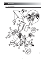
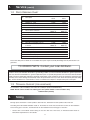
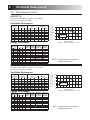
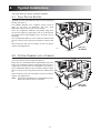
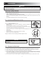
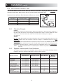
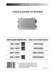
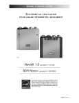
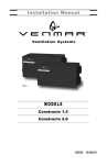
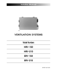
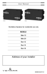
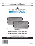
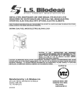
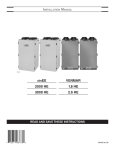
I NSTALLER M ANUAL V ENTILATION SYSTEMS FOR RESIDENTIAL USE ONLY VB0157 Novofit 1.5* Novofit 2.0 (Part no. 43121) (Part no. 45121) *This product earned the ENERGY STAR® by meeting strict energy efficiency guidelines set by Natural Resources Canada and the US EPA. It meets ENERGY STAR requirements only when used in Canada. 07997 rev. 08 About this Manual This manual uses the following symbols to emphasize particular information: ! WARNING Identifies an instruction which, if not followed, might cause serious personal injuries including possibility of death. CAUTION Denotes an instruction which, if not followed, may severely damage the unit and/or its components. NOTE: Indicates supplementary information needed to fully complete an instruction. ! WARNING When performing installation, servicing or cleaning the unit, it is recommended to wear safety glasses and gloves. CAUTION This unit is intended for residential use only. NOTE: This installation manual refers to Novoclimat™ requirements. The specifications are subject to change without notice. For more details, refer to Novoclimat program. Novoclimat is a performing dwelling concept created by the Agence de l’efficacité énergétique of Québec, to insure comfort, health and savings for the occupants. Many requirements, mainly for the building envelope, tightness and ventilation must be met for a house to be Novoclimat certified. Venmar has conceived a unit with all the HRV features required by this concept. Please note that Novoclimat also has specific requirements regarding the system and ducts installation and balancing. 2 Table of Contents 1. SERVICE ............................................................................................4-5 1.1 3-D Drawing ..................................................................................................4 1.2 Parts Ordering Chart ....................................................................................5 1.3 Technical Support ..........................................................................................5 2. 3. SIZING..................................................................................................5 TECHNICAL DATA ................................................................................6-7 3.1 3.2 3.3 3.4 3.5 4. Air Distribution ..............................................................................................6 Defrost Cycles ..............................................................................................6 Dimensions ....................................................................................................6 Specifications ................................................................................................6 Performance Charts ......................................................................................7 TYPICAL INSTALLATIONS ..........................................................................8 4.1 Fully Ducted System......................................................................................8 4.2 System Combined with a Furnace ................................................................8 5. INSTALLATION ..................................................................................9-13 5.1 Locating and Mounting the Unit ....................................................................9 5.2 Planning the Ductwork ..................................................................................9 5.3 Calculating the Duct Size ............................................................................10 5.3.1 Example of Calculation......................................................................10 5.3.2 Registers Location and Air Flows Distribution ..................................10 5.4 Installing the Ductwork and Registers ........................................................11 5.4.1 Fully Ducted System ........................................................................11 5.4.2 System Combined with a Furnace ....................................................11 5.5 Connecting the Ducts to the Unit ................................................................12 5.6 Installing the Exterior Hoods........................................................................13 5.7 Connecting the Drain ..................................................................................13 6. MAIN CONTROLS ............................................................................14-16 6.1 Dimensions and Specifications....................................................................14 6.2 Main Control Installation ........................................................................14-15 6.2.1 Altitude Main Control Installation..................................................14-15 6.2.2 Deco-Touch Main Control Installation................................................15 6.3 Electrical Connection to the Furnace ..........................................................16 7. 8. 9. WIRING DIAGRAM ................................................................................17 AIR FLOW BALANCING ........................................................................18 OVERALL VERIFICATION ........................................................................19 9.1 Main Controls ..............................................................................................19 9.2 Auxiliary Controls ........................................................................................19 10. 11. 12. MAINTENANCE/INSTRUCTIONS FOR USER ..............................................20 TROUBLESHOOTING ........................................................................21-22 REFERENCES ......................................................................................22 3 4 VL0038 3 2 1 19 4 6 5 17 9 7 8 16 3 11 15 14 8 12 10 13 1.1 18 14 1. Service 3-D DRAWING 1. Service 1.2 (cont’d) PARTS ORDERING CHART No. 1 2 3 4 5 Double Collar Port no. 2 Damper no. 1 (kit) Damper Rod (kit) Electronic Board & Spacers (kit) Thermistor (kit) 6 Door Latches & Screws 7 8 9 10 11 12 13 Damper Actuator Assembly Filter Small Basic Filter Blower Assembly Square Damper (kit) Door Ass’y (including 12 & 13) Door Latches (keeper) & Screws Hinge Ass’y (kit) Heat Recovery Core Balancing Double Collar Port Balancing Damper Drain Connector (kit) Door Switch (SPST), E69 10A 14 15 16 17 18 19 NOVOFIT 1.5 43121 02257 12454 13037 13038 12895 00886 (2) 00601 (4) 13734 03308 09300 12908 13033 17205 00887 (2) 00601 (4) 13036 03322 02256 02253 03203 01825 Description NOVOFIT 2.0 45121 02257 12454 13037 13038 12895 00886 (2) 00601 (4) 13734 03308 09300 12912 13033 17205 00887 (2) 00601 (4) 13036 03322 02256 02253 03203 01825 Please note that parts not listed are not available; those parts require assembly knowledge that only manufacturer can guarantee. TO ORDER PARTS: Contact your local distributor. REPLACEMENT PARTS AND REPAIR In order to ensure your ventilation unit remains in good working condition, you must use Venmar Ventilation Inc. genuine replacement parts only. The Venmar Ventilation Inc. genuine replacement parts are specially designed for each unit and are manufactured to comply with all the applicable certification standards and maintain a high standard of safety. Any third party replacement part used may cause serious damage and drastically reduce the performance level of your unit, which will result in premature failing. Also, Venmar Ventilation Inc. recommends to contact a certified service depot for all replacement parts and repairs. 1.3 TECHNICAL SUPPORT (FOR ASSISTANCE) For assistance, call on weekdays, from 8:30 a.m. to 5:00 p.m. (Eastern Standard Time). NOTE: Do not call this number for ordering parts. This phone number is for the installers only. 1-800-649-0372 (toll-free) 2. Sizing On high speed, the Novofit 1.5 units produce about 150 cfm, and Novofit 2.0 units produce about 189 cfm. According to the Novoclimat Ventilation needs vs. the number of rooms chart, the Novofit 1.5 units can be installed in house having up to 13 rooms*, and Novofit 2.0 can be installed in house having up to 16 rooms*. * Houses with a non finished section having an area less than 2/3 of the house, or without basement. Refer to Novoclimat requirements for more details. 5 3. Technical Data 3.1 AIR DISTRIBUTION NORMAL OPERATION STALE DEFROST AND/OR RECIRCULATION MODE FRESH AIR TO OUTSIDE FILTERED AIR TO BUILDING VF0016 FRESH STALE AIR FROM OUTSIDE 3.2 VF0018 AIR STALE FROM BUILDING AIR FROM BUILDING DEFROST CYCLES Outside Temperature Celcius (°C) Fahrenheit (°F) Defrost Cycles Defrosting (min.) Extended Defrost Cycles Operation time Defrosting (min.) (min.) between each defrost cycle -5 IN AIR TO BUILDING 23 6 60 10 30 -15 5 6 32 10 20 -27 -17 6 20 10 15 A COLD REGION, SET UP 3.3 Operation time (min.) between each defrost cycle EXTENDED DEFROST BY REMOVING JUMPER JU1F OFF THE CIRCUIT BOARD. DIMENSIONS 6” (152 mm) 30¼” (768 mm) 171/8” (435 mm) 16½” (419 mm) VK0029A 3.4 SPECIFICATIONS Model Novofit 1.5 Novofit 2.0 Weight 65 lb (29.5 kg) 67 lb (30.5 kg) Port Diameter 6” (152 mm) 6” (152 mm) 1/2” (12 mm) 1/2” (12 mm) Drain Diameter Installation Motor Speed Electrical supply Chains and springs (provided with the unit) High and low speed factory set (optional increased or decreased low speed) 120 V, 60 Hz 120 V, 60 Hz 150 watts 240 watts Power Consumption 6 3. Technical Data (cont’d) 3.5 PERFORMANCE CHARTS NOVOFIT 1.5 ELECTRICAL REQUIREMENTS: 120 VOLTS, 1.3 EXHAUST AIR TRANSFER RATIO: 0.01 AMPERES. EXT. STATIC PRESSURE Pa in. w.g. 25 0.1 50 0.2 75 0.3 100 0.4 125 0.5 150 0.6 175 0.7 NET SUPPLY AIR FLOW l/s cfm m³/h 85 180 306 82 174 295 77 163 277 71 150 256 67 141 241 60 128 216 51 108 184 l/s 86 82 77 71 67 61 52 GROSS SUPPLY cfm m³/h 182 310 175 295 164 277 151 256 142 241 130 220 110 187 AIR FLOW l/s 92 86 81 71 57 40 27 EXHAUST cfm m³/h 194 331 182 310 171 292 151 256 120 205 85 144 57 97 EXTERNAL STATIC PRESSURE IN. W.G. (PA= N X 248.8) Ventilation Performance 0.8 0.6 0.4 SUPPLY (L/S) EXHAUST (L/S) 0.2 VG0086A 0 50 0 TEMPERATURE NET °C °F HEATING 0 32 0 32 0 32 -25 -13 -25 -13 L /S AIR FLOW CFM M³/H 31 66 111 40 86 144 57 120 205 38 81 137 - COOLING 35 95 35 95 POWER SENSIBLE - - 200 X 3.6) APPARENT LATENT/RECOVERY SENSIBLE CONSUMED RECOVERY MOISTURE WATTS EFFICIENCY EFFECTIVENESS TRANSFER 62 75 90 83 - 67 64 61 60 TOTAL - 150 GROSS AIR FLOW: CFM (L/S = CFM X 0.47) (M³/H = L/S Energy Performance SUPPLY 100 - 79 75 70 76 - -0.01 -0.01 -0.01 0.02 - RECOVERY EFFICIENCY NOT TESTED - NOTE: All specifications are subject to change without notice. NOVOFIT 2.0 ELECTRICAL REQUIREMENTS: 120 VOLTS, 2.1 EXHAUST AIR TRANSFER RATIO: 0.01 AMPERES. EXT. STATIC PRESSURE Pa in. w.g. 25 0.1 50 0.2 75 0.3 100 0.4 125 0.5 150 0.6 175 0.7 GROSS NET SUPPLY AIR FLOW SUPPLY l/s cfm m³/h l/s cfm m³/h 110 234 396 112 237 403 103 219 374 105 223 378 98 208 353 100 211 360 89 189 320 91 192 328 84 177 302 85 180 306 71 151 256 72 153 259 64 136 230 65 138 234 AIR FLOW l/s 112 106 99 91 82 70 44 EXHAUST cfm m³/h 237 403 225 382 210 356 193 328 174 295 149 252 94 158 Energy Performance SUPPLY TEMPERATURE NET °C °F HEATING 0 32 0 32 0 32 -25 -13 -25 -13 COOLING 35 95 35 95 L /S 0.8 0.6 0.4 SUPPLY (L/S) EXHAUST (L/S) 0.2 0 50 VG0015A 100 150 200 GROSS AIR FLOW: CFM (L/S = CFM X 0.47) (M³/H = L/S 250 X 3.6) POWER SENSIBLE APPARENT LATENT/RECOVERY SENSIBLE CONSUMED RECOVERY MOISTURE M³/H WATTS EFFICIENCY EFFECTIVENESS TRANSFER AIR FLOW CFM 56 119 202 86 182 310 34 72 122 - 124 197 114 - 60 53 62 TOTAL - EXTERNAL STATIC PRESSURE IN. W.G. (PA= N X 248.8) Ventilation Performance - - - 70 62 80 - -0.01 -0.01 0.08 - RECOVERY EFFICIENCY NOT TESTED - 7 NOTE: All specifications are subject to change without notice. 4. Typical Installations There are three (2) common installation methods. 4.1 FULLY DUCTED SYSTEM (Primarily for homes with radiant hot water or electric baseboard heating. See Figure 1.) The complete ductwork of the ventilation system consists in ducts for the fresh air distribution and other ducts dedicated to exhaust moist, stale air to the outside. Fresh air is supplied to bedrooms and principal living areas (at least one register per level). Moist, stale air is exhausted to the outside from the high humidity areas in the home, such as bathrooms. Use an independent bathroom fan in washroom (without a bath tub nor a shower) and a range hood in kitchen to exhaust stale air. Homes with more than one level require at least one exhaust register at the highest level. See 5.4.1 for details VH0062 Figure 1 4.2 SYSTEM COMBINED WITH A FURNACE (For homes with forced air heating. See Figure 2.) Moist, stale air is exhausted from the high humidity areas in the home, such as bathrooms, kitchen and laundry room. Fresh air is supplied to the cold air return or the supply duct of the furnace. Use an independent bathroom fan in washroom (without a bath tub nor a shower) and a range hood in kitchen to exhaust stale air. Homes with more than one level require at least one exhaust register at the highest level. NOTE: For this type of installation, it is essential that the furnace blower runs when the unit is in operation. See 5.4.2 for details VH0063 Figure 2 8 5. Installation ! WARNING When applicable local regulation comprises more restrictive installation and/or certification requirements, the aforementioned requirements prevail on those of this document and the installer agrees to conform to these at his own expenses. INSPECTING THE BOX CONTENT • • • • Inspect the exterior of the unit for shipping damage. Ensure that there is no damage to the door, door latches, door hinges, dampers, duct collars, cabinet, etc. Inspect the interior of the unit for damage. Ensure that the fan motor assembly, heat recovery core, insulation, dampers, damper actuator and condensation tray are all intact. If the unit was damaged during shipping, contact your local distributor. (Claims must be made within 24 hours after delivery.) Use checklist included with the unit to ensure that no parts are missing. 5.1 LOCATING AND MOUNTING THE UNIT Choose an appropriate location for the unit: • Within an area of the house where the temperature is kept above 10°C/50°F and below 40°C/104°F. • Away from living areas (dining room, living room, bedroom), if possible. • So as to provide easy access to the interior cabinet for every three months and annual maintenance, and to the control panel on the side of the unit. • Close to an exterior wall, so as to limit the length of the insulated flexible duct to and from the unit. • Close to a drain. • Away from hot chimneys, electrical panel and other fire hazards. • Allow for a power source (standard outlet). VD0037 Figure 3 Hang the unit with the 4 chains and springs provided (see Figures 3 and 4). VD0038 Figure 4 1/8” (3 mm) CAUTION Make sure the unit is level, with a 1/8’’ (3 mm) tilt backwards (see Figure 5). VD0039A Figure 5 5.2 a) b) c) d) e) PLANNING THE DUCTWORK Follow the instructions in Section 5.3 on next page to determine the appropriate duct diameters for your system. Keep it simple. Plan for a minimum number of bends and joints. Keep the length of insulated duct to a minimum. Do not use wall cavities as ducts. Do not use branch lines smaller than 4” (102 mm) Ø. Do not ventilate crawl spaces or cold rooms. Do not attempt to recover the exhaust air from a dryer or a range hood. This would cause clogging of the recovery module. Use rigid ducts for fresh air distribution and stale air exhaust (“warm” side of HRV) and sheet metal for the kitchen exhaust duct (if need be). Be sure to plan for at least one exhaust register on the highest lived-in level of the house if it has 2 floors or more. 9 5. Installation 5.3 (cont’d) CALCULATING THE DUCT SIZE Use the table below to ensure that the ducts you intend to install will be carrying air flows at/or under the maximum air flow values. Never install a duct if its air flow exceeds the maximum value. NOVOCLIMAT CHART FOR SIZE OF DUCT CONNECTED TO REGISTER VS. AIR FLOW ROUND DUCT RECTANGULAR DUCT MAXIMUM AIR 4” 2¼” OR 3¼” X 10” 40 CFM 5” 2¼” OR 3¼” X 10” 65 CFM 6” 3¼” OR 4” X 10” 110 FLOW END BRANCHES 5”Ø 55 CFM MAIN BRANCH 6”Ø 110 CFM CFM VI0003 Figure 6 5.3.1 Calculation Example: Problem: My installation requires two exhaust registers (both for the bathrooms). I will connect these registers to a main duct which will connect to the unit (high speed performance value of 110 cfm). What size of duct should I use for the main exhaust duct and for the two end branches leading to the registers? (See Figure 6.) Solution: Main duct: Table above indicates a 6” Ø duct: maximum air flow: 110 cfm. The high speed air flow of 110 cfm equals the maximum value (110). Therefore a 6” Ø duct or larger is an appropriate choice for the main exhaust duct. End branches: Each end branch will have to transport an air flow of 55 cfm (110 divided by 2). Table above indicates a 5” Ø duct: maximum air flow: 65 cfm. The high speed air flow of 55 cfm is far enough away from the maximum value (65). Therefore a 5” Ø duct or larger is an appropriate choice for the 2 end branches. NOTE: A 4” Ø duct would have been too small because the maximum acceptable value for a 4” Ø duct is 40 cfm 5.3.2 Registers Location and Air Flows Distribution: The registers location and the air flow distribution must be taken in account when performing ductwork installation. Refer to the Novoclimat table below to plan the registers location. FRESH AIR FLOWS REGISTERS LOCATION KITCHEN DINING ROOM LIVING ROOM OFFICE RECREATION ROOM MASTER BEDROOM SECONDARY BEDROOM(S) MAIN BATHROOM SECONDARY BATHROOM(S) LAUNDRY ROOM WORKSHOP NON-FINISHED BASEMENT MINIMUM REQUIRED 4.7 4.7 4.7 4.7 9.4 4.7 L/S L/S L/S L/S L/S L/S 4.7 L/S (10 (10 (10 (10 (20 (10 (10 CFM) CFM) CFM) CFM) CFM) CFM) CFM) MAXIMUM ACCEPTABLE 11.8 L/S (25 CFM 18.9 L/S (40 CFM) 9.4 L/S (20 CFM) 18.9 L/S (40 CFM) 9.4 L/S (20 CFM) 9.4 L/S (20 CFM) 18.9 L/S (40 CFM) 10 EXHAUST AIR FLOWS MINIMUM REQUIRED 0 23.6 L/S (50 14.2 L/S (30 0 0 - CFM) CFM) MAXIMUM ACCEPTABLE 23.6 L/S (50 CFM) 51.9 L/S (110 CFM) 51.9 L/S (110 CFM) 23.6 L/S (50 CFM) 5. 5.4 Installation (cont’d) INSTALLING THE DUCTWORK AND REGISTERS ! WARNING Never install a stale air exhaust register in a room where there is a combustion device, such as a gas furnace, a gas water heater or a fireplace. CAUTION The ductwork is intended to be installed in compliance with all local and national codes that are applicable. 5.4.1 Fully Ducted System (as illustrated in Section 4.1) Stale air exhaust ductwork: • • • • Install registers in areas where contaminants are produced: bathrooms, laundry room, etc. Install registers 6 to 12 inches (152 to 305 mm) from the ceiling on an interior wall OR install them in the ceiling (the duct leading to the register must never go through the attic). If a register is installed in the kitchen, it must have a washable filter and be located at least 4 feet (1.2 m) from the range. If possible, measure the velocity of the air flowing through the registers. If the velocity is higher than 400 ft/min. (122 m/min), then the register type is too small. Replace with a larger one. Fresh air distribution ductwork: • • Install registers in every bedrooms, in living room and a minimum of one per level without bedroom nor living room. Install registers high on the walls with air flow directed towards the ceiling. The horizontal draft must be perceptible at 3 ft. (910 mm) from register. (The cooler air will then cross the upper part of the room and mix with room air before descending to occupant level.) 5.4.2 System Combined with a Furnace (as illustrated in Section 4.2) Stale air exhaust ductwork: (same as for Fully Ducted System, described on point 5.4.1) Fresh air distribution: ! WARNING When performing duct connection to the furnace, installation must be done in accordance with all applicable codes and standards. Please refer to your local building code. • • • Cut an opening into the furnace return duct not less than 10 feet (3.1 m) from the furnace (A+B). Connect this opening to one end of the top section of a metal T coupling (the T will be reversed, see shaded part in Figure 7). Connect the other end of the T coupling top section to the fresh air distribution port of the HRV (see Figure 7). NOTE: For this case, it is essential that the furnace blower runs when the unit is in operation. Synchronize the furnace blower operation with the HRV operation (see Section 6.3). A B VJ0051 A+B = not less than 10’ (3.1 m) Figure 7 11 5. Installation 5.5 (cont’d) CONNECTING THE DUCTS TO THE UNIT Insulated flexible duct Use the following procedure for connecting the insulated flexible duct to the ports on the unit (exhaust to outside and fresh air from outside). a) Pull back the insulation to expose the flexible duct. b) Connect the interior flexible duct to the port using a duct tie. c) Carefully seal the connection with duct tape. d) Pull the insulation over the joint and tuck it between the inner and outer rings of the double collar. e) Pull the vapor barrier over the insulation and over the outer ring of the double collar. f) Apply duct tape to the joint making an airtight seal. Avoid compressing the insulation when you pull the tape tightly around the joint. Compressed insulation loses its R value and causes water dripping due to condensation on the exterior surface of the duct. CAUTION Make sure that the vapor barrier on the insulated ducts does not tear during installation to avoid condensation within the duct. a) VJ0001 b) c) d), e) f) VJ0002 VJ0003 VJ0004 VJ0005 Rigid ducts Use duct tape to connect the rigid ducts to the ports. CAUTION Do not use screws to connect rigid ducts to the ports. Make sure that the 2 balancing dampers are left in a fully open position before connecting the ducts to these ports (fresh air distribution port and stale air exhaust port as shown on Figure 8). VJ0007 Figure 8 12 5. Installation 5.6 (cont’d) INSTALLING THE EXTERIOR HOODS Choose an appropriate location for installing the exterior hoods: • at a minimum distance of 6 feet (1.8 m) between the hoods to avoid cross-contamination • at a minimum distance of 18 inches (457 mm) from the ground 6” Ø (152 MM) EXHAUST HOOD INTAKE HOOD 18” (457 MM) 6’ (1.8 M) ! WARNING Make sure the intake hood is at least 6 feet (1.8 m) away from any of the following: • Dryer exhaust, high efficiency furnace vent, central vacuum vent • Gas meter exhaust, gas barbecue-grill • Any exhaust from a combustion source • Garbage bin and any other source of contamination 18” (457 MM) 6’ (1.8 M) OPTIONAL DUCT TAPE AND DUCT TIE LOCATION 18” (457 MM) CAULKING Refer to figure 9 for connecting the insulated duct to the hoods. Place the “FRESH AIR INTAKE” sticker, provided in the installation kit, on corresponding hood. An “Anti-Gust Intake Hood” should be installed in regions where a lot of snow is expected to fall. Figure 9 VD0028 5.7 CONNECTING THE DRAIN Inside view ± 12" (± 305 mm) 1 VO0010 To install the drain fittings, punch the 2 knock-out sections located at the bottom of the unit. 2 VO0008 In order to keep the drain pan intact, hand tighten the 2 plastic drain fittings to the unit using the gaskets, washers and nuts as shown. TIE-WRAP ± 1” VO0011 TO DRAIN 4 Make a water trap loop in the tube to prevent the unit from drawing unpleasant odors from the drain source. Make sure this loop is situated BELOW the “T” as shown. This will prevent water from being drawn back up into the unit in case of negative pressure. Run the tube to the floor drain or to an alternative drain pipe or pail. Be sure there is a slight slope for the run-off. 5 VD0231A If using a pail to collect water, locate the tube end approximately 1” from the top of the pail in order to prevent water from being drawn back up into the unit. 13 VO0005A ± 12" (± 305 mm) 3 Cut 2 sections of plastic tubing, about 12” (305 mm) long and attach them to each drain fitting. Join the 2 short sections to the “T” junction and main tube as shown. 6. Main Controls 6.1 DIMENSIONS AND SPECIFICATIONS DECO-TOUCH WALL CONTROL ALTITUDE WALL CONTROL 1" (26 mm) 2¾" (70 mm) 4¼" (107 mm) 4½" (114 mm) 4" (102 mm) VC0105A FRONT VIEW VOLTAGE: 6.2 VC0118A SIDE VIEW VOLTAGE: 12 volts DC 12 volts DC MAIN CONTROL INSTALLATION ! WARNING Always disconnect the unit before making any connections. Failure in disconnecting power could result in electrical shock or damage of the wall control or electronic module inside the unit. CAUTION Failure to comply with the following can cause erratic operation of the unit: • Never install more than one main wall control per unit. • Keep control low voltage wiring at least 1 foot (305 mm) away from motors, lighting ballast, light dimming circuit and power distribution panel. Do not route control wiring alongside house power wiring. • Ensure the wires are securely connected. 6.2.1 ALTITUDE MAIN CONTROL INSTALLATION 1. Route the cable from the unit to a convenient location for the wall control. 4. 2. Detach the front module from the mounting plate by pulling the bottom part. VC0102 3. Run the cable (4 wires) through the central opening of the mounting plate and mount this plate to the wall using screws (not included). If needed, use wall anchors (not included). Splice back the end of the cable to access the 4 wires. Strip the end of each wire. Connect each wire to its corresponding terminal on the back of the front module: YELLOW wire to “Y”, RED wire to “R”, GREEN wire to “G” and BLACK wire to “B”. YELLOW WIRE RED WIRE GREEN WIRE BLACK WIRE VE0173 CAUTION Be careful not to pinch wires when reinstalling the front module on its back plate. 5. VC0103 14 Reinstall the front module over the back plate. 6. Main Controls 6.2 (cont’d) MAIN CONTROL INSTALLATION (CONT’D) 6.2.1 ALTITUDE MAIN CONTROL INSTALLATION (CONT’D) 6. Connect the wires to their corresponding position inside the electrial compartment. Make sure the connections of the unit and of the wall control correspond exactly. MODE PREF SET SMART 7. Connect the auxiliary controls. 8. Do the appropriate connection to the furnace (if applicable) by referring to Section 6.3. 9. NOTE: If you are in a cold region, set up “extended defrost” by removing jumper JU1F on the main circuit board inside the electrical compartment (see Section 7). F F I OC OL Y R G B VE0177 10. Plug in the unit and do the “overall verification” of the system as described in Section 9. 6.2.2 DECO-TOUCH MAIN CONTROL INSTALLATION 1. Cut a 2 7/8” x 1 ³/8” hole in wall at a convenient location for the wall control. Route the cable from the unit to this hole. 5. Mount the wall control to the wall. NOTE: D i m e n s i o n s shown are for an installation without wall box. 2. Temporarily place the switch over the hole and mark both mounting screw hole positions. 3. Remove the switch, drill both screw holes (Ø 3/16”) in wall and insert wall anchors (included). 4. Strip the end of the cable to access the 4 wires. Strip the end of each wire. Using a small flat blade screwdriver, connect each wire to its corresponding terminal on the back of the wall control: YELLOW wire to “Y”, RED wire to “R”, GREEN wire to “G” and BLACK wire to “B”. VC0115 6. Connect the wires to their corresponding position inside the electrial compartment. Make sure the connections of the unit and of the wall control correspond exactly. Ø 3/16”, typ. VC0116A VE0251 F F I OC OL Y R G B 7. Connect the auxiliary controls. 8. Do the appropriate connection to the furnace (if applicable) by referring to Section 6.3. Y 9. R G B NOTE: If you are in a cold region, set up “extended defrost” by removing jumper JU1F on the main circuit board inside the electrical compartment (see Section 7). 10. Plug in the unit and do the “overall verification” of the system as described in Section 9. VE0243 15 6. Main Controls 6.3 (cont’d) ELECTRICAL CONNECTION TO THE FURNACE ! WARNING Never connect a 120-volt AC circuit to the terminals of the furnace interlock (standard wiring). Only use the low voltage class 2 circuit of the furnace blower control. For a furnace connected to cooling system: On some older thermostats, energizing the “R” and “G” terminals at the furnace has the effect of energizing “Y” at the thermostat and thereby turning on the cooling system. If you identify this type of thermostat, you must use the “alternate furnace interlock wiring”. An additional control relay will then have to be installed. Standard furnace interlock wiring W G Y THERMOSTAT TERMINALS W UNIT CONTROL CONNECTOR J3 9 8 7 6 5 4 3 2 1 FOUR WIRES TWO WIRES heating only R Alternate furnace interlock wiring F F 4 WIRES 2 WIRES (heating only) I OC OL Y R G B W W R RR G G R G Y wiring nuts C Y YY FURNACE 24-VOLT TERMINAL BLOCK FURNACE 24-VOLT TERMINAL BLOCK TWO WIRES COOLING SYSTEM VE0010A VE0009A 16 1 4 77 2 5 8 3 6 9 GRAY RED BROWN GREEN NC C Unit Control Module 9-PIN AMP PLUG J1 THERMOSTAT TERMINAL NO COM BLUE *FURNACE INTERLOCK RELAY 2 WIRES COOLING SYSTEM *FURNACE INTERLOCK RELAY, PART NO. 12658 17 LOW VOLTAGE AND FIELD WIRE LINE VOLTAGE ELECTRONIC ASSEMBLY T1 W BK GY BK O NO BL BL G F1 NOTE 7 LINE BK G W NEMA-15P 5-15 PLUG W1 BL BL G DAMPER MOTOR M2 MAIN EARTHING POINT G 3 2 1 X2 X1 M1 GY NEUTRAL O HIGH G BN R LOW NC BN BL MEDIUM R (NOTE 2) FAN MOTOR GY 12 O 3 G NEUTRAL DOOR INTERLOCK SWITCH S1 COM BL BL NOTES R OVERRIDE SWITCH NOTE 5 OVERRIDE SWITCH OPTIONAL OVERRIDE LED R BK Y 120V 60 Hz C1 FURNACE BLOWER NOTES 5, 6 OPTIONAL INTERLOCK WALL CONTROL WALL CONTROL WALL CONTROL WALL CONTROL BK G R Y NOTES 1, 5 Connection 120V 60Hz Logic S1 J1 4 J1 6 J3 1 K5 RELAY K2 RELAY A1 J1 9 JU 1 2 1 IN IN OUT OUT OUT OUT IN IN OUT IN OUT OUT STANDARD MODE EXTENDED DEFROST NC MED M1 J1 8 J1 1 NEUTRAL J1 2 6/32 6/20 10/30 10/20 10/15 6/60 DEFROST/VENTILATION MINUTES 23°F 5°F -22°F -5°C -15°C -27°C DEFROST TIME DAMPER MOTOR M2 HIGH FAN MOTOR LOW FUNCTION TABLE RELAY MODE K1 K2 K4* K5 Intermittent 0 0 0 1 Exchange Low 1 0 1 0 Exchange High 1 1 1 0 Circulation Low 1 0 1 1 Circulation High 1 1 1 1 Defrost Cycle 1 1 1 1 Off 0 0 0 1 0 = Relay coil is de-energized 1 = Relay coil is energized * On special mode, K4 is cycling 10 min. ON and 20 min. OFF OUT OUT JU1A JU1B JU1C JU1D JU1E JU1F JU1G A B C D E F G TYPE FURNACE BLOWER INTERLOCK CLASS 2 CIRCUIT ONLY J3 2 ELECTRONIC ASSEMBLY K1 RELAY K4 RELAY J1 3 JUMPERS TABLE VE0018A FROM MAIN .. .. .. .. .. .. .. 1- Controls available. See Section 6 (Low voltage only, 12VDC). 2- The factory set wiring for blower speed selection is high and low. Medium speed can be selected instead of low speed. Disconnect the RED wire from the motor RED tap and connect it to the motor BLUE tap. 3- If any of the original wire, as supplied, must be replaced, use the same or equivalent wire. 4- Use the factory supplied protective tubing. 5- The field wiring must comply with applicable codes, ordonnances and regulations. 6- The furnace fan circuit must be class 2 circuit only. 7- SPECIFIED UL LISTED/CSA CERTIFIED LINE FUSE. LittelFuse (225 003), 2AG Fast-Acting Fuse, 224/225 Series, Rating: 3A. VE0017A R1 DEFROST TEMPERATURE SENSOR J1 A1 NOTE 4 COLOR CODE NC NO CONNECTION O ORANGE R RED W WHITE Y YELLOW ABCDEFG BLACK BLUE BROWN GREEN GREY J4 JU1 2 1 3 2 1 BK BL BN G GY Models: Novofit 1.5 & Novofit 2.0 1 2 3 4 5 6 7 8 9 J3 4 6 F F I OCOLY RG B 7 9 7. Wiring Diagram ! WARNING Risk of electric shocks. Before performing any maintenance or servicing, always disconnect the unit from its power source. This product employs overload protection (fuse). A blown fuse indicates an overload or short-circuit situation. If the fuse blows, unplug the product from the outlet. Replace the fuse as per the servicing instructions (follow product marking for proper fuse rating) and check the product. If the replacement fuse blows, a short-circuit may be present and the product should be discarded or returned to an authorized service facility for examination and/or repair. 8. Air Flow Balancing WHAT YOU NEED TO BALANCE THE UNIT • • A magnehelic gauge capable of measuring 0 to 0.5 inch of water (0 to 125 Pa) and 2 plastic tubes. The balancing chart provided with the unit. VP0009 PRELIMINARY STAGES TO BALANCE THE UNIT • • • • Seal all the unit ductwork with tape. Close all windows and doors. Turn off all exhaust devices such as range hood, dryer and bathroom fans. Make sure the balancing dampers are fully open. Make sure all filters are clean (if it is not the first time you balance the unit). BALANCING PROCEDURE VD0051 1. Set the unit to high speed: Make sure that the furnace blower is ON if the installation is in any way connected to the ductwork of the cold air return. If the outside temperature is below 0°C/32°F, make sure the unit is not running in defrost while balancing. (By waiting 10 minutes after plugging the unit in, you are assured that the unit is not in a defrost cycle.) 2. Place the magnehelic gauge on a level surface and adjust it to zero. 3. Connect tubing from gauge to EXHAUST air flow pressure taps (see diagram). Be sure to connect the tubes to their appropriate high/low fittings. If the gauge drops below zero, reverse the tubing connections. NOTE: It is suggested to start with the exhaust air flow reading because the exhaust has typically more restriction than the fresh air. Place the magnehelic gauge upright and level. Record equivalent AIR FLOW of the reading according to the balancing chart on the unit. 4. Move tubing to FRESH air flow pressure taps (see diagram). Adjust the fresh air balancing damper until the fresh air flow is approximately the same as the EXHAUST air flow. If fresh air flow is less than exhaust air flow, then go back and adjust the exhaust balancing damper to equal the fresh air flow. 5. Fresh air flow VP0010 Exhaust air flow Secure both dampers in place with a fastening screw. VD0052 6. Write the required air flow information on a label and stick it near the unit for future reference (date, maximum speed air flows, your name, phone number and business address). NOTE: The air flows are acceptable up to a difference of ± 15% between the cfm home needs and the intake or exhaust airflow, but the difference between both airflows must not exceed 10%. 18 9. Overall Verification 9.1 MAIN CONTROLS This procedure allows the installer to verify that all modes of operation are fully functional. During the verification of the main control, make sure that all remote controls are inactive. ALTITUDE At its very start-up, the Altitude wall control will perform a booting sequence before being ready to operate. The booting sequence is done when the hour display is flashing. Refer to the installation sheet included with the Altitude wall control for more details in programming and setting preferences. MODE PREF SET SMART VC0101 DECO-TOUCH Refer to the installation sheet included with the Deco-Touch wall control. VC0117 9.2 AUXILIARY CONTROLS First, turn OFF the main control device before checking the remote auxiliary controls. 20/40/60-MINUTE 60-MINUTE PUSH-BUTTON TIMER: CRANK TIMER: Activate the timer. Activate the push button. Within 2 seconds, push one time for 20 minutes, two times for 40 minutes or three times for a 60-minute activation. Results expected: Motor speed: high for up to 60 minutes. 20 min. 40 min. OFF 10 20 50 60 min. 40 Results expected: 1. Motor speed: high for 20, 40 or 60 minutes. MINUTES 2. Indicator light goes “ON” and flashes every 5 seconds (one time to indicate a 20-minute operation, two times for a 40-minute, and three times for a 60-minute operation). 3. Air exchange indicator light goes « ON » Turn Past HOLD 60 VC0007 VC0017 NOTE: To stop activation, push one more time. 19 30 10. Maintenance/Instructions for User ! WARNING Risk of electric shocks. Before performing any maintenance or servicing, always disconnect the unit from its power source. • Review with the user the steps required for the regular maintenance of her/his ventilation system. These steps are described in detail in the user manual: FOUR TIMES A YEAR: • • • • Inspect the intake hood, and clean if needed. Clean the filters. Clean the interior of the cabinet and clean the door. Clean the condensation tray and inspect the drain tubing. ONCE A YEAR: • • • • Clean the heat recovery core. Clean the blades of the blower wheels if needed. Warn the user of the necessity to rebalance the system following a major house renovation or following the installation of any extra registers. Make sure the user understands how to use the main control as described in the user manual. CAUTION Do not oil the motor. It is already permanently lubricated. 20 11. Troubleshooting If the unit does not work properly, reset the unit by unplugging it for one minute and then replug it. If it still not working properly, refer to table below. NOTE: Be sure to unplug and inspect the unit before proceeding with these steps. Start-up troubleshooting: Problems Possible causes You should try this 1. The error code E1 is displayed on Altitude or Deco-Touch wall control screen. • The wires may be in reverse position. • The wires may be broken. • The wires may have a bad connection. • Ensure that the color coded wires have been connected to their appropriate places. • Inspect every wire and replace any that are damaged. • Ensure the wires are correctly connected. 2. There is no outside temperature displayed on Altitude wall control screen . NOTE: At its very start-up or after a power failure, it takes some minutes before the outside temperature appears on screen. The delay duration depends on which operation mode the wall control is set. The shortest delay is obtained when the wall control is set on MIN or MAX in VENT Mode. • Replace the unit thermistor. • The unit thermistor is defective. 3. Altitude or Deco-Touch wall control screen alternates between normal display and E3. • The Altitude or Deco-Touch • Replace the Altitude or Deco-Touch wall control. wall control is defective. 4. On Altitude wall control, there is an important difference between temperature displayed and real temperature. • The unit thermistor is defective. • The unit damper has been blocked or broken. • Replace the unit thermistor. 5. Unit doesn't work. • The circuit board may be defective. • Unplug the unit. Disconnect the main control and the optional control(s). Jump B and G (BLACK and GREEN) terminals. Plug the unit. If the motor runs on high speed and the damper opens, the circuit board is not defective. • The power cord fuse may be blown. • Unplug the unit. Unscrew the fuse holder (grey circle on illustration beside). Check if the fuse is blown (the strand is broken). If it is blown, replace the fuse according to the specifications on the unit power cord tag. 6. The damper actuator does not work. • The 9-pin connector may have a loose connection. • The damper actuator may be defective. • The circuit board may be defective. 21 • Check for the proper operation of the unit damper; replace if necessary. B G VE0082 VE0194 • Plug the unit and check to make sure all the crimp connections are secured. Check the damper actuator connections as well. • Feed 120 V directly to the damper actuator. If the problem persists, replace the damper actuator. • Replace the circuit board if the problem is not solved by the above. 11. Troubleshooting (cont’d) Problems Possible causes You should try this 7. The wall control does not work. • The wires may be in reverse position. • The wires may be broken. • There may be a short-circuit. • The wire in the wall OR the wall control may be defective. • Ensure that the color coded wires have been connected to their appropriate places. • Inspect every wire and replace any that are damaged. • With the help of a multimeter, check for continuity. • Jump B and G (BLACK and GREEN). If unit switches to high speed, remove the B G wall control and test it right beside the unit using another shorter wire. If the wall control works there, change the wire. If it doesn’t, change the wall control. • If the unit does not switch to high speed, replace the circuit board. • The circuit board may be defective. 8. The 20/40/60-min. • The 20/40/60-min. push-button timer does push button not work OR its indicator may be defective. light does not stay on. VE0082 • Jump the OL and OC terminals. If the unit switches to high speed, remove the push button and test it right beside the unit using another shorter wire. If it works there, change the wire. If it does not, change the push button. OL OC VE0067 9. The defrost cycle does not work (the fresh air duct is frozen OR the fresh air distributed is very cold). • Ice deposits may be hindering the damper operation. • The damper rod or the port damper itself may be broken. • The damper actuator may be defective. • The circuit board may be defective. • The thermistor may be defective. 12. • • • Remove the ice. • Inspect these parts and replace if necessary. • Plug in the unit and select “MIN” or “MAX” Press the door switch and see if the port damper opens. If it does not open, feed 120V directly to the damper actuator. If the port damper still doesn’t open, replace the damper actuator. • Unplug the unit. Unplug the defrost sensor wire (see J4 on electrical diagram Section 7 ). Plug the unit back in. Make sure the unit is adjusted for low speed operation (select the Ventilation Mode on the main wall control and adjust it at “MIN”). Wait 3 minutes. The unit should switch to high speed and the damper at the fresh air intake port should close (defrost mode). If this doesn’t happen, then replace the circuit board. • If the defrost mode works well after having disconnected the thermistor wire (above test), this means the thermistor is probably defective. You should replace it. References HVI, “Installation Manual for Heat Recovery Ventilators”, 1987 edition. ASHRAE 1984 Systems Handbook, chapter 11, “Air Distribution Design for Small Heating and Cooling Systems”. Venmar Quality Assurance R 2000 22