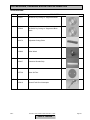
1
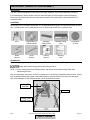
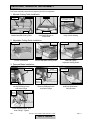
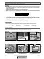
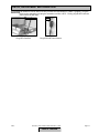
BX-3 BRICK XTREME
DRY BRICK SAW
OWNER’S MANUAL &
OPERATING INSTRUCTIONS
CAUTION:
Read all safety and
operating instructions
before using this
equipment
Enter the Serial Number of your new saw in the
space below. The Serial Number is located on the
left side of the blade guard.
SERIAL NUMBER:
NOTE:
For your (1) one year warranty to be effective,
complete the warranty card (including the Serial
Number) and mail it in as soon as possible.
Table of Contents
INTRODUCTION and TABLE OF CONTENTS
INTRODUCTION:
We at MK Diamond want to congratulate you on selecting the BX-3 Dry Brick Saw. We are certain that you
will be pleased with your purchase. MK Diamond takes pride in producing the finest products in the industry.
Operated correctly, your BX-3 should provide you with years of quality service. In order to help you, we have
included this manual. This owners manual contains information necessary to operate and maintain your BX-3
safely and correctly. Please take a few minutes to familiarize yourself with the BX-3 by reading and reviewing
this manual.
If you should have questions concerning your BX-3, please feel free to call our friendly customer service
department at: 800 421-5830
TABLE OF CONTENTS
Page
SAFETY:
Safety Messages
Damage Prevention Message
General Safety Precautions and Hazard Symbols
California Proposition 65 Message
Electrical Requirements and Grounding Instructions
Safety Label Locations
Brick Saw Specific Warnings
Product Specifications
3
3
3
5
6
8
8
9
UNPACKING AND ASSEMBLY
Unpacking
Contents
Transport
Assembly
10
10
10
11
SETUP, ADJUSTMENT AND OPERATION
Setup
Adjustment and Operation
Cleanup
12
14
17
MAINTENANCE AND TROUBLESHOOTING
Maintenance
Troubleshooting
18
24
EXPLODED VIEW AND PARTS LIST
Exploded View
Parts List
26
27
THEORY
Theory of Diamond Blades
29
ACCESSORIES, ORDERING and RETURN INSTRUCTIONS
Accessories
Ordering Information
Return Material Policy
Packaging Instructions
Authorized Service Centers
30
31
31
31
31
Manual Part No. 158168
BX-3
Revision 11/00, Effective Date November 1, 2000
Revision No. 2
Page 2
SAFETY
Read and follow all safety, operating and maintenance instructions. Failure to read and follow these
instructions could result in injury or death to you or others. Failure to read and follow these instructions could
also result in damage and/or reduced equipment life.
SAFETY MESSAGES:
Safety messages inform the user about potential hazards that could lead to injury, death and/or equipment
damage. Each safety message will be preceded by one of the following (3) three words that identify the
severity of the message.
Not following instructions WILL lead to DEATH or SERIOUS INJURY
Not following instructions COULD lead to DEATH or SERIOUS INJURY
Not following instructions CAN lead to injury
DAMAGE PREVENTION AND INFORMATION MESSAGES:
A Damage Prevention Message is to inform the user of important information and/or instructions that could
lead to equipment or other property damage if not followed. Information Messages convey information that
pertains to the equipment being used. Each message will be preceded by the word NOTE, as in the example
below.
NOTE:
Equipment and/or property damage may result if these instructions are not followed.
GENERAL SAFETY PRECAUTIONS AND HAZARD SYMBOLS:
In order to prevent injury, the following safety precautions and symbols should be followed at all times!
Safety Precautions:
KEEP GUARDS IN PLACE.
In order to prevent injury, keep guards in place and in working order at all times.
REMOVE ADJUSTING KEYS AND WRENCHES.
Form a habit of checking to see that keys and adjusting wrenches are removed from the power tool before it
is turned on.
KEEP WORK AREA CLEAN.
Cluttered work areas and benches invite accidents.
DO NOT USE IN DANGEROUS ENVIRONMENTS.
Do not use power tools in damp or wet locations nor expose them to rain. Always keep the work area well
lighted.
KEEP CHILDREN AWAY.
All visitors and children should be kept a safe distance from work area.
MAKE THE WORKSHOP KID PROOF.
Make the workshops kid proof by using padlocks, master switches or by removing starter keys.
DO NOT FORCE THE TOOL.
A power tool will do a job better and safer operating at the rate for which it was designed.
USE THE RIGHT TOOL.
Do not force a tool or an attachment, to do a job that it was not designed to do.
BX-3
Revision 11/00, Effective Date November 1, 2000
Table of Contents
Page 3
SAFETY
USE THE PROPER EXTENSION CORD.
If using an extension cord make sure it is in good condition first. When using an extension cord, be sure to
use one heavy enough to carry the current your product will draw. An undersized cord will cause a drop in
line voltage that will result in a loss of power and overheating. TABLE 1, Page 7 shows the correct AWG
size to use depending on cord length and nameplate ampere rating. If in doubt, use the next heavier gage.
The smaller the gage number, the heavier the cord.
WEAR PROPER APPAREL.
Do not wear loose clothing, gloves, neckties, rings, bracelets, or other jewelry that may be caught in moving
parts. Non-slip footwear is recommended. Wear protective hair covering to contain long hair.
ALWAYS USE SAFETY GLASSES.
Safety glasses should always be worn when working around power tools. In addition, a face,
dust mask or respirator should be worn if a cutting operation is dusty. Everyday eyeglasses only
have impact resistant lenses and may not prevent eye injury-they are NOT safety glasses.
SECURE WORK.
Clamps or a vise should be used to hold work whenever practical. Keeping your hands free to operate a
power tool is safer.
DO NOT OVERREACH.
Keep proper footing and balance at all times by not overreaching.
MAINTAIN TOOLS WITH CARE.
Keep tools clean for the best and safest performance. Always follow maintenance instructions for
lubricating, and when changing accessories.
DISCONNECT TOOLS.
Power tools should always be disconnected before servicing or when changing accessories, such as blades,
bits, cutters, and the like.
REDUCE THE RISK OF UNINTENTIONAL STARTING.
Make sure the trigger switch; locking button is in the RELEASE position before plugging in a power
tool.
USE RECOMMENDED ACCESSORIES.
Consult the owner's manual for recommended accessories. Using improper accessories may increase the
risk of personal or by-stander injury.
NEVER STAND ON THE TOOL.
Serious injury could occur if a power tool is tipped, or if a cutting tool is unintentionally contacted.
CHECK FOR DAMAGED PARTS.
Before using a power tool, check for damaged parts. A guard or any other part that is damaged should be
carefully checked to determine it would operate properly and perform its intended function. Always check
moving parts for proper alignment or binding. Check for broken parts and mountings and all other conditions
that may affect the operation of the power tool. A guard, or any damaged part, should be properly repaired
or replaced.
DIRECTION OF FEED.
Always feed work into a blade or cutter against the direction of rotation. A blade or cutter should always be
installed such that rotation is in the direction of the arrow imprinted on the side of the blade or cutter.
NEVER LEAVE A TOOL RUNNING UNATTENDED – TURN POWER OFF.
Do not leave a tool until it comes to a complete stop. Always turn a power tool OFF when leaving the work
area, or, when a cut is finished.
BX-3
Revision 11/00, Effective Date November 1, 2000
Table of Contents
Page 4
SAFETY
Hazard Symbols:
ELECTRICAL SHOCK!
Never touch electrical wires or components while the motor is running. Exposed, frayed or worn
electrical motor wiring can be sources of electrical shock that could cause severe injury or burns.
ACCIDENTAL STARTS!
Before plugging the equipment into an electrical outlet, be sure the trigger switch, locking button is in
the "RELEASE" position to prevent accidental starting. Unplug the power tool before performing any
service operation.
ROTATING OR MOVING PARTS!
Keep hands, feet, hair, and clothing away from all moving parts to prevent injury. Never operate a
power tool with covers, shrouds, or guards removed.
Sawing and drilling generates dust. Excessive airborne particles may cause irritation to eyes, skin and
respiratory tract. To avoid breathing impairment, always employ dust controls and protection suitable to the
material being sawed or drilled; See OSHA (29 CFR Part 1910.1200). Diamond Blades improperly used are
dangerous. Comply with American National Standards Institute Safety Code, B7.1 and, Occupational Safety
and Health Act covering Speed, Safety Guards, Flanges, Mounting Procedures, General Operating Rules,
Handling, Storage and General Machine Conditions.
CALIFORNIA PROPOSITION 65 MESSAGE:
Some dust created by power sanding, sawing, grinding, drilling, and other construction activities contain
chemicals known [to the State of California] to cause cancer, birth defects or other reproductive harm. Some
examples of these chemicals are:
• Lead, from lead-based paints
• Crystalline silica, from bricks and cement and other masonry products and
• Arsenic and chromium, from chemically treated lumber
Your risk from these exposures varies depending on how often you do this type of work. To reduce your
exposure to these chemicals, work in a well-ventilated area, and work with approved safety equipment, such
as those dust masks that are specially designed to filter out microscopic particles.
BX-3
Revision 11/00, Effective Date November 1, 2000
Table of Contents
Page 5
SAFETY
ELECTRICAL REQUIREMENTS AND GROUNDING INSTRUCTIONS:
In order to prevent potential electrical shock and injury, the following electrical safety precautions and symbols
should be followed at all times!
In case of a malfunction or breakdown, grounding provides a path of least resistance for electric
current to reduce the risk of electric shock. This tool is equipped with an electric cord having an
equipment-grounding conductor and a grounding plug. The plug must be plugged into a matching
outlet that is properly installed and grounded in accordance with all local codes and ordinances.
• Do not modify the plug provided – if it will not fit the outlet; have the proper outlet installed by a
qualified electrician
• Improper connections of the equipment-grounding conductor can result in a risk of electric shock.
The equipment-grounding conductor is the insulated conductor that has an outer surface that is
green, with or without yellow stripes. If repair or replacement of the electric cord or plug is
necessary, do not connect the equipment-grounding conductor to a live terminal
• Check with a qualified electrician or service personnel if the grounding instructions are not
completely understood, or if in doubt as to whether the tool is properly grounded
• Use only 3-wire extension cords that have 3-prong grounding plugs and 3-pole receptacles that
accept the tool's plug
• Repair or replace a damaged or worn cord immediately
Grounding
Pin
This tool is intended for use on a circuit that has an outlet that looks like the one shown in Sketch A
of Figure 1. The tool has a grounding plug that looks like the plug illustrated in Sketch A of FIGURE
1. A temporary adapter, which looks like the adapter illustrated in sketches B and C, may be used to
connect this plug to a 2-pole receptacle as shown in Sketch B, if a
properly grounded outlet is not available. The temporary adapter
should be used only until a properly grounded outlet can be
Metal Screw
installed by a qualified electrician. The green-colored rigid ear,
CCover of Grounded
Outlet Box
lug, and the like, extending from the adapter, must be connected
(A)
(B)
to a permanent ground such as a properly grounded outlet box.
ADAPTER
(C)
Grounding
Means
Grounding
Pin
NOTE: Use of a temporary adapter is not permitted in Canada.
(D)
FIGURE 1
To reduce the risk of electrocution, keep all connections dry and off the ground.
A Ground Fault Circuit Interrupter (GFCI) should be provided on the circuit(s) or outlet(s) to be used
for the Brick Saw. Receptacles are available having built-in GFCI protections and may be used for
this measure of safety.
When using an extension cord, the GFCI should be installed closest to the power source, followed
by the extension cord and lastly, the saw.
BX-3
Revision 11/00, Effective Date November 1, 2000
Table of Contents
Page 6
SAFETY
Power
Cord
To avoid the possibly of the appliance plug or receptacle getting wet, position the Brick Saw to one
side of a wall mounted receptacle. This will prevent water from dripping onto the receptacle or plug.
A "drip loop," shown in FIGURE 2, should be arranged by the user to properly position the power
cord relative to the power source.
The "drip loop" is that part of the cord below the level of the receptacle, or
Power
Tool
the connector, if an extension cord is used. This method of positioning the
Supporting
Surface
cord prevents the travel of water along the power cord and coming in
contact with the receptacle.
If the plug or receptacle gets wet, DO NOT unplug the cord. Disconnect
the fuse or circuit breaker that supplies power to the tool. Then unplug and
examine for presence of water in the receptacle.
Drip Loop
FIGURE 2
Use only extensions cords that are intended for outdoor use. These extension cords are identified
by a marking "Acceptable for use with outdoor appliances; store indoors while not in use." Use only
extension cords having an electrical rating not less than the rating of the product. Do not use
damaged extension cords. Examine extension cords before using and replace if damaged. Do not
abuse extension cords and do not yank on any cord to disconnect. Keep cords away from heat and
sharp edges. Always disconnect the extension cord from the receptacle before disconnection the
product form the extension cord.
Use of undersize extension cords result in low voltage to the motor that can result in motor burnout
and premature failure. MK Diamond warns that equipment returned to us showing signs of being run
in a low voltage condition, through the use of undersized extension cords will be repaired or replaced
totally at the customers expense. There will be no warranty claim.
To choose the proper extension cord,
• Locate the length of extension cord needed in TABLE 1 below.
• Once the proper length is found, move down the column to obtain the correct AWG size required
for that length of extension cord.
As an example, a fifty (50) foot extension cord would require an AWG size of 16.
Extension Cord Minimum Gage for Length
Volts
120V
BX-3
25 ft.
AWG
14
Total Length of Cord in Feet
50 ft.
100 ft
150 ft.
AWG
AWG
AWG
12
Not Recommended
TABLE 1
Revision 11/00, Effective Date November 1, 2000
Table of Contents
Page 7
SAFETY
SAFETY LABEL LOCATIONS:
Safety labels are located according to Figures 1 to 4 below. The labels contain important safety information.
Please read the information contained on each safety label. These labels are considered a permanent part of
your saw. If a label comes off or becomes hard to read, contact MK Diamond or your dealer for a
replacement
Item
1.
2.
3.
4.
Location
Left Side, Upper Cross Member
Right Side, Upper Cross Member
Back, Upper Cross Member
Blade Guard
Description
Caution Safety Label
Dust Inhalation Warning Label
Extension Cord Warning Label
Serial Number and Motor Specifications
1
2
3
4
Part No.
155576
154337
155672
158096
BRICK SAW SPECIFIC WARNINGS:
Ø Read Owners Manual
Ø Wear Protective Gear for –
BX-3
•
•
•
•
Head
Lungs
Ear
Eye
Revision 11/00, Effective Date November 1, 2000
Table of Contents
Page 8
SAFETY
PRODUCT SPECIFICATIONS:
The BX-3 is a versatile lightweight, dry, masonry saw. Operated and used according to this manual, the BX-3
will provide years of dependable service.
General Description:
The BX-3, Brick Xtreme, is engineered as a 14" dry saw, consisting of a powerful 115v motor in a hard plastic
case. The saw is capable of cutting brick and masonry up to 8" x 8" x 16" in size; the blade has a five (5) inch
cutting depth.
Motor and Weight Specifications:
Motor and Weight specifications for the BX-3 are listed in Table 2 below.
Voltage
Amperage
Frequency
RPM
Weight
115 v
13 A
60 Hz
3,500 rpm
45 lbs.*
Table 2
Blade Capacity:
The BX-3 uses a 14-inch diameter segmented dry MK Diamond blade with a .110-inch cutting width.
Masonry Types:
The BX-3 can cut a variety of masonry types including, cinder block, slump stone block, wall brick, paver
brick, concrete block and cylinders, roofing tile, marble, granite, decorative rock or almost any other nonferrous material.
NOTE:
The BX-3 is not designed to cut plastic or ferrous (metals) material.
Spring Assisted Cutting Head:
The BX-3 is designed with a spring assisted Cutting Head to allow for easier step cutting. The Cutting Head
can be locked in the down position when cutting smaller pieces.
Lockable Trigger Switch:
The BX-3 is designed with a lockable trigger-operating switch in the handle to allow for ease of operation.
Removable Motor Air Filter:
The BX-3 is designed with an easy clean motor air filter to extend the life of the motor.
Replaceable Motor Brushes:
The BX-3 is designed with replaceable motor brushes to extend operating life.
*Without Movable Cutting Table
BX-3
Revision 11/00, Effective Date November 1, 2000
Table of Contents
Page 9
UNPACKING, TRANSPORT and ASSEMBLY
UNPACKING:
Your BX-3 has been shipped from the factory thoroughly inspected. Only minimal assembly is required.
If not already done, remove the BX-3 from the carton and place it on a flat surface. Remove Strapping.
Remove the Accessories box from the main carton and place along side the BX-3 (Owners Manual is in
Accessories Box).
CONTENTS:
In the containers, you will find one (1) BX-3, one (1) 14 inch segmented dry diamond blade (or segmented
block blade), one (1) movable cutting table, one (1) adjustable cutting guide, one replacement motor air filter,
one (1) blade wrench, one (1) shaft wrench, one (1) owner's manual and one (1) warranty card.
BX-3
Segmented Dry
Diamond Blade
Adjustable
Cutting Guide
Movable Cutting
Table
Shaft
Wrench
Owner's
Manual
Warranty
Card
Extra Motor
Air Filter
- OR -
Blade
Wrench
TRANSPORT:
The BX-3 weighs approximately forty (45) pounds (Without the Movable Cutting Table), making transport easy.
Always observe safe lifting practices when lifting the BX-3.
NOTE: Lock the Cutting Head in the DOWN position, and remove the Movable Cutting Table when
transporting the BX-3.
Due to its lightweight construction, the BX-3 is designed to be carried by the durable aluminum frame. Simply
lock the spring assisted cutting head in the DOWN position, grasp the frame by the lower front and upper
back cross members, lift and transport the BX-3 to the desired work location
Locking Pin
Inserted
Lift Point
Cutting Head
Locked Down
BX-3
Revision 11/00, Effective Date November 1, 2000
Table of Contents
Page 10
UNPACKING, TRANSPORT and ASSEMBLY
ASSEMBLY:
Follow the assembly instructions to prepare your BX-3 for operation.
1. Movable Cutting Table Installation:
Cutting Table
Front
Roller Wheels
Ease of Movement
(See Maintenance Section
If Problems Arise)
Guide Rails
Guide Rail
Roller Wheels
(A)
Position Movable Cutting Table
(B)
Seat Roller Wheels on
Guide Rails
(C)
Verify Correct Seating
2. Adjustable Cutting Guide Installation:
Turn to Loosen
Align
Parallel Slots
Turn to Tighten
Seated
Ruler/Stop
(A)
Loosen Thumbscrew
(B)
Position Adjustable Cutting Guide
(C)
Seat and Tighten
Adjustable Cutting Guide
3. Diamond Blade Installation:
NOTE: When installing the Retaining Screw, do not “cross-thread" and DO NOT over tighten the screw.
Motor Shaft
Hold Shaft
Wrench
Stationary
Outer Flange
(B)
Remove Retaining Screw
and Outer Flange
(A)
Identify Retaining Screw
and Outer Flange
Hold Shaft
Wrench
Stationary
Rotate Blade
Wrench
Counter-clockwise
Retaining Screw
Seat Blade on
Inner Flange
Rotation Direction
(C)
Install and Seat Blade –
Verify Rotation
Rotate Blade
Wrench Clockwise
(D)
Install Retaining Screw and
Outer Flange - Tighten
BX-3
Revision 11/00, Effective Date November 1, 2000
Table of Contents
Page 11
SETUP, ADJUSTMENT and OPERATION
SETUP:
•
•
•
Before powering or starting, check for damage that could prevent this equipment from proper operation or
performing its intended function. Check for binding and alignment of moving parts. Check for damaged,
broken, or missing parts.
Verify the trigger switch, locking button is in the "RELEASE" position.
Before connecting the BX-3 to a power supply, be sure the voltage, cycle and phase of the job site power
source meet the requirements of TABLE 3
VOLTAGE:
CYCLE:
PHASE:
•
•
•
115v
60hz
single phase
TABLE 3
If using an extension power cord, make sure the length and wire gauge corresponds to the requirements
listed in TABLE 1 on page 7. An extension power cord that is too small in wire gauge (diameter), or too
long in length, will cause the motor to overheat and could cause premature failure.
Use an approved Ground Fault Circuit Interrupter (GFCI)
Do not cover the motor vents as this could lead to motor overheating.
Portable Generator:
If using a portable generator to provide power, ensure the generator meets the following minimum
requirements:
8 kW
120/240 volts
66.7/33.3 amps
Single Phase
Pre-start Inspection:
The pre-start inspection should be performed before beginning any job.
NOTE: In order to avoid breaker tripping, a 20-amp circuit breaker should be used.
If the Diamond Blade shows signs of fatigue cracking, replace the blade before starting work.
Cracks
Ease of Movement
(See Maintenance Section
if Problems Arise)
Replace if Excessively Grooved
(See Maintenance Section
if Problems Arise)
(A)
Inspect Blade for Damage – Verify
Blade Correct for Material Being Cut
(B)
Inspect Wooden Strip for
Excessive Grooves
Check for Cleanliness
(See Maintenance Section)
(C)
Movable Cutting Table
Moves Freely
Trigger Lock
(Push to Lock)
Trigger Switch
(Push to Unlock)
Inspection
Points
Underside of Handle
(D)
Inspect for Damage
BX-3
(E)
Inspect Motor Air Filter for
Cleanliness
Revision 11/00, Effective Date November 1, 2000
Table of Contents
(F)
Verify Trigger Switch Unlocked
Page 12
SETUP, ADJUSTMENT and OPERATION
If an extension cord is used, first verify it meets the requirements of TABLE 1 (page 9). Plug the
BX-3 into the extension cord; plug the extension cord into a GFCI. Finally, plug the GFCI into the
power source in that order.
GFCI
(G)
Plug GFCI into BX-3
BX-3
Power
Source
(H)
Plug GFCI into Power Source
Revision 11/00, Effective Date November 1, 2000
Table of Contents
Page 13
SETUP, ADJUSTMENT and OPERATION
ADJUSTMENT AND OPERATION:
1. Cutting Setup:
Ruler/Stop
Set Edge of Cutting
Guide to Desired Cut
Length on Ruler/Stop
Ruler Markings
(A)
Set Adjustable Cutting Guide
Set against Adjustable
Cutting Guide and
Ruler/Stop
Adjustable
Cutting Guide
Ruler/Stop
(B)
Position Masonry Piece
DO NOT FORCE the blade to cut, it will do the job better and safer at rate for which it was
designed.
2. Step Cuts:
A Step Cut is performed when a series of small cuts of increasing depth are used to complete a single cut.
Step Cuts are used for large objects or for hard objects such as Firebrick and Pavers.
NOTE: 1. Step Cutting is the preferred cutting method for all cuts.
2. When cutting hard material Step Cutting should always be used.
3. Step Cutting will extend the life of the Diamond Blade.
Depress Trigger to
Start (Lock if Desired)
Hold Work
in Position
(A)
Step Cut Setup
Lower Cutting
Head 1/4 -1/2
Inch During
Push Stroke
Lower Cutting
Head Additional
1/4 -1/2 Inch During
Pull Stroke
Pull Direction
Push Direction
(B)
Step Cut “Push” Stroke
(C)
Step Cut “Pull” Stroke
Release Trigger Switch
Repeat “Push”
and “Pull” Strokes
Until Cut Complete
(D)
Repeat Steps B and C
Until Cut Complete
BX-3
Raise Cutting
Head
Allow Blade to
Stop Before
Removing Work
(E)
Cutting Complete
Revision 11/00, Effective Date November 1, 2000
Table of Contents
Page 14
SETUP, ADJUSTMENT and OPERATION
3. Chop Cutting:
A Chop Cut is performed by cutting completely through an object in one pass.
Depress Trigger to
Start (Lock if Desired)
Hold Roller
Trolley Stationery
Lower Cutting
Head Smoothly
to Cut
Continue to Lower
Cutting Head until
Cut Complete
Position
Work Below
Cutting Head
(B)
Lower Cutting Head
to Begin Cutting
(A)
Chop Cut Setup
(C)
Continue Lowering Head
until Cut Complete
Release Trigger Switch
Raise Cutting
Head
Allow Blade to
Stop Before
Removing Work
(D)
Cutting Complete
4. Cutting with the Cutting Head Locked Down:
This method is preferred when cutting small objects.
Lock Trigger Switch
Align Holes and
Lock Cutting
Head in Position
(A)
Lock Cutting Head in
the Down Position
Unlock Trigger Switch
When Cut Complete
(B)
Locked Cutting Head Setup
Push Slowly to Cut
(C)
Slowly Push Piece toward Blade
to Begin the Cut
Allow Blade to
Stop Before
Removing Work
Remove Locking
Pin to Release
Cutting Head
Continue to Push
until Cut Complete
(D)
Continue Pushing Piece into
Blade until Cut Complete
BX-3
Hold Work
in Position
Push Slowly to Cut
Hold in Position
(E)
Cutting Complete
Revision 11/00, Effective Date November 1, 2000
Table of Contents
Page 15
SETUP, ADJUSTMENT and OPERATION
5. Angle Cuts:
Angle Cuts may be performed using the Step Cut, Chop Cut or the Locked Cutting Head cutting methods.
The following is utilizing the Locked Cutting Head method.
Turn to Loosen
Remove Adjustable
Cutting Guide
Adjustable
Cutting Guide
Ruler/Stop
(A)
Remove Adjustable
Cutting Guide
Set against Adjustable
Cutting Guide and
Ruler/Stop
Align 45° Slots
to Ruler/Stop
(B)
Reposition Adjustable
Cutting Guide
Ruler/Stop
(C)
Position Adjustable
Cutting Guide
DO NOT FORCE TOOL, it will do the job better and safer at the rate for which it was designed.
Lock Trigger Switch
Align Holes and
Lock Cutting
Head in Position
(E)
Locked Cutting Head Setup
(D)
Lock Cutting Head in
the Down Position
Unlock Trigger
Switch when
Cut Complete
(G)
Continue Pushing Piece into
Blade until Cut Complete
Push Slowly to Cut
(F)
Slowly Push Piece toward Blade
to Begin the Cut
Unlock Trigger
Switch when
Cut Complete
Allow Blade to
Stop Before
Removing Work
Continue to Push
until Cut Complete
BX-3
Hold Work
in Position
(H)
Cutting Complete
Revision 11/00, Effective Date November 1, 2000
Table of Contents
Remove Locking
Pin to Release
Cutting Head
Hold in Position
(I)
Release Cutting Head
Page 16
SETUP, ADJUSTMENT and OPERATION
6. Cleanup:
Power
Source
GFCI
(A)
Unplug GFCI from Power Source
(B)
Unplug GFCI from BX-3
Pull Straight Back
To Remove Cap
(C)
Remove Motor Filter Cap
Always wear eye protection when using compressed air.
Pull Foam Filter
Out of Filter Cap
Install Foam Filter
into Filter Cap
Tap on Hard
Surface to
Dislodge Dirt
(D)
Remove Filter from Filter Cap
Push Filter Cap
onto Spacer
Pins to seat
Align Filter Cap
Retaining Clips
to Spacer Pins
(G)
Install Motor Filter
Cap onto Motor
BX-3
(E)
Clean Filter by Tapping on Hard
Surface or using Compressed Air
(F)
Reinstall Filter into Filter Cap
Clean Roller
Wheels
Clean Guide Rails
(H)
Clean the Movable Cutting Table
Roller Wheels and Guide Rails
Revision 11/00, Effective Date November 1, 2000
Table of Contents
Clean BX-3
Using Clean Cloth
(I)
Clean Remainder of BX-3
Page 17
MAINTENANCE AND TROUBLESHOOTING
MAINTENANCE:
1. General Maintenance:
The following maintenance should be performed following each use. Use Light oil, such as WD-40 or 3 in 1
when lubricating parts.
Lubricate
Torsion Spring
Lubricate
Roller Wheels
Lubricate Guide Rails
(A)
Lubricate Cutting Head
Torsion Spring
(B)
Lubricate Movable Cutting Table
Roller Wheels and Guide Rails
2. Monthly Maintenance:
The following should be performed monthly. Items should be lubricated as directed.
Clean and
Lubricate
Inspect for
Wear
Clean and Lubricate
(A)
Clean and Lubricate Inner Flange
and Motor Shaft
BX-3
(B)
Clean and Lubricate
Blade Retaining Screw
Revision 11/00, Effective Date November 1, 2000
Table of Contents
(C)
Check Roller Wheels and
Guide Rails for Wear
Page 18
MAINTENANCE AND TROUBLESHOOTING
3. Blade Dressing:
Like most cutting instruments, a diamond blade performs best when it is dressed. Over time and use,
diamonds on the outer edge will become smooth or “glazed” over. This will reduce grinding efficiency and
may cause the blade to “wander” or bend, giving the illusion of an alignment problem. When this occurs, the
blade will need to be dressed. The diamond blade can be dressed using the MK Dressing Stick (part number
152792) and by following the steps below.
Ruler/Stop
Set up for Operation
(See Setup, Adjustment
and Operation)
(A)
Set BX-3 for Operation
Set Edge of Cutting
Guide to Desired Cut
Length on Ruler/Stop
Ruler Markings
(B)
Set Adjustable Cutting Guide
to Cut 1/16-inch Strips
Set against Adjustable
Cutting Guide and
Ruler/Stop
Adjustable
Cutting Guide
Ruler/Stop
(C)
Position Dressing Stick
DON'T FORCE TOOL, it will do the job better and safer at the rate for which it was designed.
Depress Trigger to
Start (Lock if Desired)
Hold Dressing
Stick in Position
(D)
Set up for Blade Dressing
Lower Cutting
Head while
Pushing Dressing
Stick into Blade
Repeat Cut
Stroke 8-times
Push Direction
(E)
Begin Blade Dressing
(F)
Repeat Cut Stroke
to Dress Blade
Release Trigger Switch
Raise Cutting
Head
Allow Blade to Stop
Before Removing
Dressing Stick
(G)
Dressing Complete
BX-3
Revision 11/00, Effective Date November 1, 2000
Table of Contents
Page 19
MAINTENANCE AND TROUBLESHOOTING
4. Diamond Blade Change-out:
Disconnect the tool before servicing and when changing accessories, such as blades, bits,
cutters, and the like.
Hold Shaft
Wrench
Stationary
Set up for Operation
(See Setup, Adjustment
and Operation)
Retaining Screw
Remove Blade
Rotate Blade
Wrench
Counter-clockwise
(A)
Setup BX-3 for Operation
(B)
Remove Retaining Screw
and Outer Flange
(C)
Remove Blade from
Motor Shaft
NOTE: When installing the Retaining Screw, do not “cross-thread" and DO NOT over tighten the screw.
Seat Blade on
Inner Flange
Hold Shaft
Wrench
Stationary
Rotate Blade
Wrench Clockwise
Rotation Direction
(D)
Install Blade Under Blade Guard
and Onto Motor Shaft
BX-3
(E)
Install Outer Flange and
Retaining Screw – Tighten
Revision 11/00, Effective Date November 1, 2000
Table of Contents
Page 20
MAINTENANCE AND TROUBLESHOOTING
5. Movable Cutting Table Wheel Change Out:
NOTE: All four (4) Movable Cutting Table, Roller Wheels should be replaced at the same time (MK Diamond
Part No. – 133090).
Rotate Wrench
Counter-clockwise
1/2-Inch Wrench
Roller Wheels
Clean Holes
(B)
Remove Roller Wheels
(A)
Place Movable Cutting
Table On Work Bench
with Roller Wheels Up
(C)
Prepare for Installation
Of New Roller Wheels
NOTE: When installing the Retaining Bolt, do not “cross-thread" and DO NOT over tighten the Nut.
Washer
Rotate Wrench
Counter-clockwise
Roller Wheel
(D)
Install Wheel/Washer Assembly
Into Movable Cutting Table
1/2-Inch Wrench
(E)
Install Roller Wheel
Retaining Nut – Tighten
Lubricate with
Light Oil (WD-40,
3 in 1, etc)
(F)
Lubricate Roller Wheels
Install Movable Cutting
Table (See Setup,
Adjustment and Operation
(G)
Install Movable Cutting Table
BX-3
Revision 11/00, Effective Date November 1, 2000
Table of Contents
Page 21
MAINTENANCE AND TROUBLESHOOTING
6. Protective Wooden Strip Replacement:
The protective wooden strip is to protect the Movable Cutting Table from damage during operation. Over
time, the wooden strip will become grooved from use. A grooved wooden strip will not support masonry
during cutting, causing the blade to "break through" the piece instead of performing a smooth cut (MK
Diamond Part No. – 156427).
Phillips
Screwdriver
Roller Wheels
Retaining Screw
(A)
Place Movable Cutting Table on
Work Bench – Wheels Up
with Roller Wheels Up
(B)
Remove the Two Protective
Wooden Strip Retaining Screws
Phillips
Screwdriver
Worn Wooden
Strip
New Wooden
Strip
(C)
Place Movable Cutting Table on
Work Bench – Wheels Down
Install Movable Cutting
Table (See Setup,
Adjustment and Operation
Retaining Screw
(D)
Replace Worn
Protective Wooden Strip
BX-3
Protective
Wooden Strip
(E)
Place Movable Cutting Table on
Work Bench – Wheels Up,
Reinstall Retaining Screws
Revision 11/00, Effective Date November 1, 2000
Table of Contents
(F)
Install Movable Cutting Table
Page 22
MAINTENANCE AND TROUBLESHOOTING
7. Motor Brush Change-out:
Disconnect the tool before servicing and when changing accessories, such as blades, bits,
cutters, and the like.
Disconnect BX-3
Clean Brush Housing
of Carbon All Carbon
Dust and Fragments
Phillips
Screwdriver
(A)
Disconnect the BX-3
Remove Motor Brush
One Cap on
Rotate Screw Driver
Either Side of Motor Counter-clockwise
(B)
Locate and Remove One
Motor Brush Cap
(C)
Remove Motor Brush and
Clean Brush Housing
NOTE: When installing motor brushes, care must be taken to ensure the spring end is straight before
installing the Motor Brush Cap.
Align Motor Brush
with Brush Housing
and Install the Brush
Rotate Screw
Driver Clockwise
Replace Second
Motor Brush
Phillips
Screwdriver
(D)
Align and Install
New Motor Brush
BX-3
(E)
Install Motor Brush Cap
Revision 11/00, Effective Date November 1, 2000
Table of Contents
(F)
Install the Second Motor Brush
(Repeat Steps B to E)
Page 23
MAINTENANCE AND TROUBLESHOOTING
TROUBLESHOOTING:
Verify the Lockable Switch is unlocked and the saw is disconnected from the power source before
performing any troubleshooting procedure.
1. Motor Stops Turning:
Verify Connected
If GFCI Tripped,
Reset and Restart
BX-3 once
If GFCI not Tripped,
go to Step C
(A)
Verify all Plugs Fully Connected
If Connected, go to Step B
If not
Tripped,
go to Step E
If Breaker Tripped,
Reset once Attempt Restart
(D)
Verify Circuit Breaker
Not Tripped
(B)
Check Ground Fault Circuit
Interrupter (GFCI) Tripped
If Circuit is 115
Volts, go to
Step F
If Circuit is
not115 Volts,
Change Circuit
(E)
Verify Source Voltage
is 115 Volts
If Less than
20 Amps,
Switch to 20
Amp Breaker
If 20 Amp
Or Greater,
go to Step D
(C)
Verify Circuit Breaker is
20 Amp or Greater
Return to
MK Diamond
for Repair
(F)
Return to MK Diamond
2. Blade Will Not Cut Properly:
If “Glazed,” Dress
(See Blade Dressing)
If not “Glazed,
go to Step B
If Rotation
Not Correct,
Reposition Blade
If Rotation
Correct, go
to Step C
If Core Bent,
Change Blade
(A)
Check for Smoothness
or “Glazing”
(B)
Check for Proper Rotation
If Core Not
Bent, go to
Step D
(C)
Ensure Blade
Core Not Bent
Contact Place of Purchase or
MK Diamond (800 421-5830)
To Verify Blade
If Blade
Correct, go
to Step E
(D)
Verify Blade Correct for
Material Being Used
BX-3
Return to
MK Diamond
for Repair
(E)
Return to MK Diamond
Revision 11/00, Effective Date November 1, 2000
Table of Contents
Page 24
MAINTENANCE AND TROUBLESHOOTING
3. Movable Cutting Table Does Not Move Correctly:
If Dirty,
Clean
Rails
If Clean, go
to Step B
(A)
Check Guide Rails Clean
If Damaged
Replace
If Not
Damaged,
go to
Step C
(B)
Check for Roller
Wheel Damage
If Binding
Present, Return
to MK Diamond
If No Binding,
go to Step D
(C)
Verify Ease and Freedom
of Movement
Return to
MK Diamond
for Repair
(D)
Return to MK Diamond
BX-3
Revision 11/00, Effective Date November 1, 2000
Table of Contents
Page 25
EXPLODED VIEW AND PARTS LIST
EXPLODED VIEW:
BX-3
Revision 11/00, Effective Date November 1, 2000
Table of Contents
Page 26
EXPLODED VIEW AND PARTS LIST
PARTS LIST:
Item
A
A1
A2
A3
A4
A5
A6
A7
A8
A9
A10
A11
A12
A13
A14
A15
A16
A17
B
B1
B2
B3
C
C1
C2
C3
C4
C5
C6
C7
C8
C9
C10
D
D1
D2
D3
D4
D5
D6
D7
D8
D9
D10
D11
D12
D13
E
E1
E2
BX-3
Description
Assembly, Frame, Right
Casting, Frame, Right
Casting, Frame, Left
Support, Horizontal Frame
Tube Connector, ¼-20
Screw, ¼-20 x 1 ½ Hex Head Cap
Washer, ¼ SAE Flat
Washer, ¼ Split Lock
Strap, Table Guide Rail
Screw, ¼-20 x ¾, Hex Head Cap
Washer, ¼ Split Lock
Drive Stud, Round Head Grooved #16 (¼) x ½
Label, Adhesive “BX3”
Label, Safety Caution
Label, MK USA
Tag, Serial, Brick Saw
Label, Prop 65
Label, Warning, Extension Cord
Assembly, Arm, Motor Mount
Casting, Arm, Motor Mount
Bushing, Nylon Flange
Label, Adhesive “Brick Xtreme”
Assembly, Pivot Clamp
Casting, Pivot Clamp
Screw, ¼-20 x 1 ¼ Socket Hd. Cap
Washer, ¼ Split Lock
Pin, Pivot ∅.625 x 5.6
Screw, Set ¼-20 x ¼ Cup Point
Spring, Torsion
Stop Block
Screw, ¼-20 x 5/8, Socket Hd Cap
Pin, Detent w/ Pull Ring
Lanyard
Assembly, Handle & Switch
Handle, Upper
Handle, Lower
Screw, M3.5 x 12mm
Screw, ¼-20 x ¾, Socket Hd. Cap
Washer, ¼ SAE, Flat
Washer, ¼ Split Lock
Insert, Expansion, ¼-20 Standard
Switch, Trigger
Plate, Screw, Switch Mounting
Cord, AC Power 120V
Cover, Wire
Screw, # 6-32 x 1 ¼, Socket Flat Head
Washer, #6 Flat SAE
Assembly, Motor
Motor, AC 115 Volt / 13 Amp, 3500 RPM
Flange, Outer
Revision 11/00, Effective Date November 1, 2000
Table of Contents
Qty
1
1
1
3
6
6
6
6
2
10
10
2
1
1
1
1
1
1
1
1
2
1
1
1
2
2
1
1
1
1
1
1
1
1
1
1
8
2
2
2
2
1
1
1
1
1
5
1
1
1
MK p/n
n/a
157367
157369
157384
157930
151914
151915
152591
157383
152370
152591
158071
157959
155576
154334
158096
154337
155672
n/a
157599
157932
157958
n/a
157593
154683
152591
157645
157528
157702
158226
152587
157933
158072
n/a
157874
157875
158156
152587
151915
152591
158147
157934
157876
157935
157880
158160
158231
n/a
157801
158105
Page 27
EXPLODED VIEW AND PARTS LIST
Item
E3
E4
E6
E7
E8
E9
E10
E11
E12
F
F1
F2
F3
F4
F5
F6
F7
F8
F10
F11
F12
H
H5
H6
H7
H8
H8-A
BX-3
Description
Flange, Inner
Screw, M10 – 1.5 x 20mm Hex Flange
Screw, M6-1 x 20mm Hex Head Cap
Washer, M6 Split Lock
Cap, Motor
Cap, Motor Filter
Spacer Pin, Cap Screw
Filter Element
Screw, #6 x 1 ½, Combo Head Pan, Tapping
Assembly, Table
Casting, Table
Stop, Rule
Screw, ¼-20 x ¾ Hex Head Cap
Nut, ¼-20, Hex w/ External Tooth Washer
Wheel, Roller
Nut, 5/16-18, Hex w/ External Tooth Washer
Wood Strip, Table Insert
Screw, #8 x 1 Pan Head Phil.
Casting, Squaring Arm
Screw, 5/16-18 x 1 ½, Thumb
Nut, 5/16-18 Square
Assembly, Accessory Pack
Wrench, Blade Nut
Wrench, Shaft
Extra Filter Element
Blade, MK-BX10, Dry Cutting 14”, Segmented
Blade, MK-BX30, Dry Cutting 14”, Segmented Block
Owner's Manual
Revision 11/00, Effective Date November 1, 2000
Table of Contents
Qty
1
1
4
4
1
1
2
1
2
1
1
1
4
4
4
4
1
2
1
1
1
1
1
1
1
1
1
1
MK p/n
158106
158107
158158
158159
157877
157878
157879
157729
158157
n/a
158144
134387
152370
153941
133090
151051
156427
151047
231276
151155
151156
n/a
158109
158110
157729
157957
157944
158168
Page 28
THEORY
THEORY OF DIAMOND BLADES:
Diamond blades do not really cut; they grind the material through friction. Diamond crystals, often visible at
the leading edge and sides of the rim/segment, remove material by scratching out particles of hard, dense
materials, or by knocking out larger particles of loosely bonded abrasive material. This process eventually
cracks or fractures the diamond particle, breaking it down into smaller pieces. As a result, a diamond blade
for cutting soft, abrasive material must have a hard metal matrix composition to resist this erosion long
enough for the exposed diamonds to be properly utilized. Conversely, a blade for cutting a hard, nonabrasive material must have a soft bond to ensure that it will erode and expose the diamonds embedded in
the matrix. These simple principles are the foundation of “controlled bond erosion”.
Types of Cutting:
There are two basic types of cutting-Dry or Wet. The choice of which type of blade to use depends on:
• The requirements of the job
• The machine/tool utilizing the diamond blade
• The preference of the operator
In the case of DRY cutting, the overwhelming popularity and quantity of hand-held saws and the flexible
nature of MK Diamond blades to professionally handle most ceramic, masonry, stone and concrete materials,
make the DRY cutting blade a very attractive tool. When using a DRY blade, the user must be aware of
distinct operating practices to ensure optimum performance. DRY cutting blades require sufficient airflow
about the blade to prevent overheating of the steel core. This is best accomplished by shallow, intermittent
cuts of the material with periods of “free-spinning” (for several seconds) between each cut, to maximize the
cooling process.
For WET cutting applications, MK has the exact blade to compliment both the material to be cut and the wet
cutting machine to be used. During cutting operations, liberal amounts of water act as a coolant to support
the cutting effectiveness and longevity of the WET blade. Additionally, using water adds to the overall safety
of cutting operations by keeping the dust signature down.
Know All You Can About the Material You Wish to Cut
BX-3
Revision 11/00, Effective Date November 1, 2000
Table of Contents
Page 29
ACCESSORIES, ORDERING and RETURN INFORMATION
ACCESSORIES:
ITEM
1.
NUMBER
DESCRIPTION
157957
MK-BX10, Dry Cutting 14" Segmented Blade
157944
MK-BX30, Dry Cutting 14" Segmented Block
Blade
231276
Adjustable Cutting Guide
133090
Roller Wheel
156427
Protective Wooden Strip
157729
Motor Air Filter
152610
Ground Fault Circuit Interrupter
2.
3.
4.
5.
6.
7.
BX-3
Revision 11/00, Effective Date November 1, 2000
Table of Contents
Page 30
ACCESSORIES, ORDERING and RETURN INFORMATION
ORDERING INFORMATION:
You may order MK Diamond products through your local MK Diamond distributor or, you may order direct
from MK Diamond.
NOTE: There is a $25.00 minimum order when ordering direct from MK Diamond. All purchases must be
made using VISA or MasterCard.
When ordering direct from MK Diamond, please have the following information ready before calling:
• The Model Number of the saw
• The Serial Number of the saw
• Where the saw was purchased and when
• The Part Number for the part(s) being ordered
• The Part Description for the part(s) being ordered
All parts may be ordered by calling toll free to – 800 421-5830 or 310 539-5221 and asking for Customer
Service. For technical questions, call – 800 474-5594.
RETURN MATERIALS POLICY:
To expedite the service relative to the return of a product purchased through MK Diamond, please observe
the following:
NOTE: When returning all items, they must have been purchased within the previous twelve (12) months.
• Have the Model Number of the saw
• Have the Serial Number of the saw
• Have the location of where the saw was purchased
• Have the date when the saw was purchased
• Contact Customer Service for approval to return the item(s)
• Obtain a Returned Goods Number (RGA) authorizing the return
• Follow the packaging instructions in the following section
• Ensure your item(s) are prepaid to the destination
For returned items, call toll free to – 800 421-5830 or 310 539-5221 and ask for Customer Service. For
technical questions, call – 800 474-5594 or 310 257-2845.
PACKAGING INSTRUCTIONS:
•
•
•
•
•
Remove the Blade guard and Support Angle Assembly
Dry the saw before shipping
When packing, include the following: BX-3, Diamond Blade, Blade guard and Support Angle Assembly
and Adjustable Cutting Guide (Other Accessories are not required)
Package the unit in its original container or one of comparable size (do not ship the unit partially exposed)
Ensure all parts are secured in the packaging to prevent moving
AUTHORIZED SERVICE CENTERS:
For quicker repair time, you may contact MK Diamond Customer Service, toll free, at – 800 421-5830 or 310
539-5221 for the Authorized Service Center closest too you. For technical questions, call – 800 474-5594.
BX-3
Revision 11/00, Effective Date November 1, 2000
Table of Contents
Page 31
BX-3 BRICK XTREME
BRICK SAW
OWNER’S MANUAL &
OPERATING INSTRUCTIONS
CALIFORNIA PROPOSITION 65 MESSAGE:
Some dust created by power sanding, sawing, grinding, drilling, and other construction activities
contain chemicals known [to the State of California] to cause cancer, birth defects or other
reproductive harm. Some examples of these chemicals are:
•
Lead, from lead-based paints
•
Crystalline silica, from bricks and cement and other masonry products and
•
Arsenic and chromium, from chemically treated lumber
Your risk from these exposures varies depending on how often you do this type of work. To reduce
your exposure to these chemicals, work in a well-ventilated area, and work with approved safety
equipment, such as those dust masks that are specially designed to filter out microscopic particles.
MK DIAMOND PRODUCTS, INC
1315 STORM PARKWAY, TORRANCE, CA 90509-2803
310 539 5158
Table of Contents