1
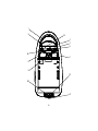
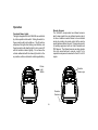
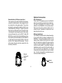
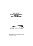
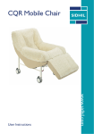
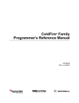
VOH681A
Ope
ion
Operr at
ation
Manual
Important Notice
Safety Precaution
It is unlawful in most jurisdictions for a person to drive
a motor vehicle which is equipped with a television
viewer or screen that is located in the motor vehicle
at any point forward of the back of the driver’s seat, or
that is visible, directly or indirectly, to the driver while
operating the vehicle. In the interest of safety, the
VOH681A should never be installed where it will be
visible, directly or indirectly, by the operator of the
motor vehicle.
For safety reasons, when changing video tapes it is
recommended that the vehicle is not in motion, and
that you do not allow children to unfasten seatbelts to
change tapes or make any adjustments to the system.
System adjustments can be accomplished using the
remote control unit, while seatbelts remain fastened.
Enjoy your Audiovox entertainment system but
remember-safety of all passengers remains the
number one priority.
Please note that the state of Rhode Island forbids the
installation of such a device in a motor vehicle.
-2-
Features
♦ 6.8” TFT (Thin Film Transistor) Active
Congratulations on your purchase of the Audiovox
VOH681A drop-down Video Monitor. The VOH681A
has been designed to give you and your family many
years of video entertainment in the mobile
environment. Please read the directions that follow
to familiarize yourself with the product and to ensure
that you obtain the best results from your equipment.
Please note: Installation options vary, see the individual
owner’s manuals for each component in your system
to obtain a full understanding of each component’s
operation.
♦
♦
♦
♦
♦
♦
♦
♦
♦
-3-
Matrix LCD (Liquid Crystal Display)
Monitor
IR transmitter for Wireless Headphones
Rear Remote Sensor Eye
Three Audio/Video Inputs
Headphone/Speaker Amplifier
Headphone Jack for Wired Headphone
Built-in Forward Remote Sensor Eye
Built-in Dome Lights
Backlit Controls for Low Light Operation
Push button screen Brightness Controls
1
2
12
3
4
5
6A
7
8
9
10
6B
11
-4-
Front Panel
9. Screen Release – Slide in direction of arrow to
release the flip down screen.
10. Headphone Jack – allows plug-in of wired
headphone with 1/8” stereo jack.
11. Auxiliary A/V Stereo Input – allows plug-in of
camcorder, game, portable DVD player or other
A/V source with RCA type output connectors.
12. Brightness Up/Down Control - use the
brightness up/down buttons to adjust the picture
to bright or dark.
1. Infrared Transmitter - Used to transmit audio to
wireless headphones.
2. Power button – (Bright red when system is On,
dim when Off).
3. Volume Up/Down – Controls volume to
headphone jacks and external speakers if
connected.
4. Source Select – used to select one of the three
A/V sources.
5. Source indicator LEDs - Indicate the current
video source.
6A. Forward Remote Sensor Eye – Receives
signals from infrared remote controls and
relays them to remote mounted equipment.
6B.Rear Remote Sensor Eye - Receives signals
from infrared remote controls and relays them
to remote mounted equipment.
7. Three position Dome Light Switch
• Auto – Automatically switches on the dome
lights in conjunction with the vehicle’s
interior illumination.
• Off – The Dome lights will not turn on in
this position.
• On – Turns on the Dome lights.
8. Dome lights – provide additional illumination.
Turning the VOH681A On or Off
1 Sliding the screen release lock forward will unlock
the LCD screen and it will drop down slightly. Pivot
the screen downward until a comfortable viewing
angle is reached. The internal friction detent will
hold the screen in position while the system is in
use.
2 Pressing the power button on the pod or the remote
will turn the system on or off alternately. When in
use the internal backlighting will illuminate the
controls.
3 After the unit has been turned on and is displaying
a picture, adjust the viewing angle and brightness
controls to optimize the picture quality.
4 Remember to turn the unit off and pivot the LCD to
the locked position when not in use.
-5-
Operation
Overhead Dome Lights
The lights integrated into the VOH681A are controlled
by a three position slide switch. Sliding the switch to
the on position will turn the lights on. The off position
will prevent the lights from turning on at all times, and
the auto position will allow the lights to turn on and off
with the vehicle’s interior lighting. Do not leave the
vehicle unattended with the dome light switch in the
on position, as this could result in a discharged battery.
Remote Sensors
The VOH681A incorporates two infrared sensors
which relay signals from any infrared remote control
to allow a remote mounted device to be controlled
simply by pointing its remote control at the remote
sensor eye mounted on the pod. This provides control
of auxiliary equipment such as Video Cassette and
DVD players. The infrared sensors can relay signals
from any manufacturer’s remote control to its
respective component connected to the AV1 or AV2
inputs.
Dome
Light
Switch
Remote
Sensor eye
Remote
Sensor eye
-6-
Optional Accessories
Wired Headphones
There is one 1/8” headphone jack on the VOH681A
that can be used with any standard stereo headphone.
This jack is controlled by the volume up / down
buttons on the VOH681A or the remote control.
Remove and save the protective plastic cover to
access the jack. Remember to replace the cover
when the jack is not in use.
External Auxiliary A/V Stereo inputs (Aux )
These inputs are provided to facilitate the temporary
connection of optional audio / video equipment, such
as a camcorder or video game system. They can be
accessed by removing their protective plastic cover
located behind the LCD hinge. To play a source with
these inputs, use RCA patch cord to connect the audio
/ video signals to their respective jacks. Mono audio
sources will require the use of an RCA Y cable (PN
0892165) to connect to both right and left inputs. Once
the connections have been made, turn the VOH681A
on and press the source selector button on the pod
until the “AUX” indicator LED illuminates. The unit
will now play the audio and video signals from the
accessory connected.
Wireless Headphones
The VOH681A includes a built in infrared transmitter
for use with Audiovox wireless headphones (PN
MVSWHS). Turning the headphone switch on, and
wearing them activates the internal micro switch
which will activate the internal IR receiver and the
volume can then be adjusted separately with the
controls on each headset. Any number of wireless
headphones can be used, but all must be within a
line of sight from the transmitter, as infrared
transmissions, like visible light travel only in a straight
line. See the documentation accompanying your
Audiovox wireless headphones.
External
Auxiliary A/V
Stereo
inputs
Infrared
Transmitter
-7-
Wired FM Modulator
Your video system may be equipped with an RF
modulator, that allows you to listen to the VOH681A’s
audio signal by tuning your vehicle’s radio to the
selected frequency, (88.7 or 89.1 - Check with your
installer) and turning on the remote mounted RF
modulator switch. (In most cases this toggle switch
will be located underneath the driver’s side of the
dash, check with your installer for the exact location.)
Whenever the RF modulator is on, broadcast radio
reception will be poor. Turning the remote mounted
toggle switch off will allow normal radio reception.
Audiovox Video Cassette Player (AV1)
In most installations a VCP will be connected to the
“AV1” input. To view a video cassette, turn the
VOH681A On and press the source button on its
control pad until the “AV1” indicator LED illuminates.
The VCP may also be operated with a remote or the
buttons on its face. The VOH681A is now ready to
play the audio and video signals from the VCP if it is
connected to the “AV1” input. Inserting a tape into the
VCP will automaticly turn it on and activate the play
mode. If a rewound tape had already been loaded
into the VCP, prior to its activation, press play on the
VCP or on the remote control to view the tape. For
more information see the operator’s manual
accompanying your VCP.
Video Output
The VOH681A provides a video output for an optional
video monitor(s). (Refer to page 7 of the installation
guide for more details.) This output will provide a video
signal that duplicates the signal displayed by the
VOH681A to an additional monitor or video display.
Please see your installer for more information.
-8-
Warnings
v Do not use any solvents or cleaning materials
when cleaning the video system.
v Do not use any abraisive cleaners, they may
scratch the screen. Use only a lightly dampened
lint free cloth to wipe the screen if it becomes dirty.
v Lock the LCD screen in the fully closed position
when not in use.
v Before putting on headphones always adjust the
volume setting to the lowest position.
v Remember to leave the dome light switch in the
off or auto positions when the vehicle is
unattended, as the dome lights, if left on, can drain
the vehicle’s battery.
v Do not put pressure on the LCD screen.
v Caution children to avoid touching or scratching
the screen, as it may become dirty or damaged.
AV2
The second video input may be connected to a DVD
player, video game system, or other audio / video input.
To play the AV2 source, turn the VOH681A on and
press the source button on the pod until the “AV2”
indicator LED illuminates. Turn the source component
on with its power button or remote control. The
VOH681A is now ready to play the audio and video
signals from the source connected to AV2 inputs.
-9-
Troubleshooting
PROBLEM
SOLUTION
Poor radio
reception (FM
modulator
installed)
• Check the condition of the
IR sensor
inoperative
Replacement Parts
Protective Plastic Cover
1023336
Optional Audiovox VCP Remote Control 0993000
vehicle’s radio antenna.
• Verify that the antenna is fully
raised.
• If a wired RF modulator has
been installed, verify that its
switch is turned to the off
position.
Specifications
LCD Backlighting
• Verify that the batteries in the
Resolution
suspect remote are fresh.
• Verify that the remote repeater
eye is not obstructed.
• Verify that the infrared
transmitter is affixed over the
sensor eye of the component
to be controlled
1152 x 234
Pixels
269,568
Operation Temperature
0 - 40º C
Storage Temperature
Expected Backlight Life
Video Display System
Audio Output
-10-
Edge Light Tube
-20 - 80º C
10,000 Hours
NTSC/PAL
0.1W @ 16 Ω
© Copyright 2001 Audiovox Electronics Corp. 150 Marcus Blvd. Hauppauge, NY 11788
128-5623C