1
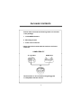
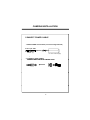
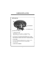
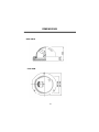
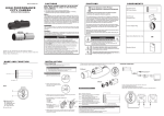
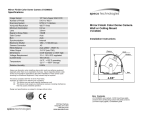
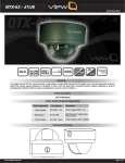
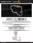
Wide Dynamic Range Dome Camera CVC624WDR 200 N New Hi Highway h Amityville, NY 11701 631-957-8700 www.specotech.com WARNING & CAUTION CAUTION RISK OF ELECTRIC SHOCK DO NOT OPEN CAUTION : TO REDUCE THE RISK OF ELECTRIC SHOCK DO NOT REMOVE COVER (OR BACK). NO USER SERVICEABLE PARTS INSIDE REFER SERVICING TO QUALIFIED SERVICE PERSONNEL._______________ The lighting flash with an arrowhead symbol, within an equilateral triangle is Intended to alert the user to the presence of un-insulated “dangerous voltage” within the product’s enclosure that may be of sufficient magnitude to constitute a risk of electric shock to persons____________________________________ The exclamation point within an equilateral triangle is intended to alert the user to the presence of important operating and maintenance (serving) instructions i n t h e l it e r a t u re a c c o m p a n y i n g t h e a p p l i a n ce _ _ _ _ _ _ _ _ _ _ _ _ _ _ _ _ _ _ I N F O R M AT I O N - T h i s e q u i p m e n t h a s b e e n t e s t e d a n d f o u n d t o c o m p a n y w i t h limits for a class a digital device Pursuant to part 15 of the FCC rules. These limits are designed to provide reasonable protection against harmful Interference W hen the equipments operated in a commercial environment. T h i s e q u i p m e n t ge n e r a t e s, u s e s, a n d C a n R a d i a t e ra d i o f r e q u e n c y e n e r g y a n d if not in sta lle d a nd u s e d in ac co rda n c e wit h th e instru ct io n m an u a l, ma y Ca u s e Ha rmf u l in t e rf e re n c e t o ra d io c o mmu n ic a t io n s . O p e ra tio n of t h is e qu i p m e n t in a residential area is likely to cause harmful interference in which C a se t h e u s e r wi l l b e r e q u i re d t o co r re ct t h e in t e rf ere n ce a t h is o wn e xp e n se . WARNING – Change or modification not expressly approved by the manufacturer could void the user’s authority to operate the equipment__________________________________ CAUTION : To prevent electric shock and risk of fire hazards. DO NOT use power sources other than that specified.______ DO NOT expose this appliance to rain or moisture.000 moisture 000 This installation should be made by a qualified service person and should conform to all local codes. 2 CONTENTS Package Contents 4 Precautions 5 Camera Installation 6-7 Features 8 OSD Menu Tree 9 OSD Menu Details 10-12 Troubleshooting 13-14 Specifications 15 Dimensions 16 Warranty 17 3 PACKAGE CONTENTS Please make sure that the following items are included in the package: 1 CVC624WDR Camera 2 Mounting Screws 1 Video Test Connector Please leave this manual with the end-user for future reference. COMPATIBILITY “A” type Box DFM Series Electrical Box is not included in the p package g but Is compatible with the camera 4 PRECAUTIONS • THIS CAMERA SHOULD BE ONLY INSTALLED BY QUALIFIED PERSONNEL • TO PREVENT A FIRE OR ELECTRICAL HAZARD PLEASE USE PROPER POWER CABLE • DO NOT CLEAN THE DOME COVER WITH AN ABRAISIVE CLEANING MATERIAL - PLEASE USE A SOFT CLOTH OR TISSUE TO CLEAN THE DOME COVER • THERE ARE NO USER-SERVICEABLE PARTS INSIDE. PLEASE DO NOT DISASSEMBLE THIS CAMERA OTHER THAN TO MAKE INITIAL ADJUSTMENTS • PLEASE USE A UL APPROVED REGULATED 12 VOLT DC POWER SUPPLY • PLEASE USE APPROPRIATE LOW VOLTAGE POWER CABLE TO PREVENT FIRE OR ELECTRICAL SHOCK • PLEASE INSURE THAT YOUR INSTALLATION AREA CAN SUPPORT THE WEIGHT OF THE CAMERA • PLEASE HANDLE THIS CAMERA CAREFULLY: - DON’T USE A STRONG OR ABRASIVE DETERGENT WHEN CLEANING THE CAMERA. - DON’T EXPOSE THE CAMERA TO DIRECT SUN 5 CAMERA INSTALLATION CONNECT POWER CABLE 1. WHEN USING 12 VOLTS DC (constant voltage 500 mA) Power Input :RED Center : (+) DC 12V Power Supply 2. CONNECT VIDEO CABLE -CONNECT CONNECT BNC CABLE TO THE BNC JACK JACK. 6 CAMERA INSTALLATION MECHANICAL (2) JOY STICK (1) Vari-focal Lens (3) Video Test Terminal (1) VARI-FOCAL LENS Adjust between TÅÆW (TELE ÅÆ WIDE) to set the angle (focal length). Set the focus by adjusting ∞ÅÆN NOTE: BOTH OF THE ABOVE ADJUSTMENTS GET LOCKED INTO POSITION THROUGH THE USE OF "LOCKING HANDLES". (2) JOY STICK TO SET THE OSD (ON SCREEN DISPLAY) , PRESS THE JOY STICK FOR ONE SECOND AND SET AS DESCRIBED IN THE MANUAL (3) VIDEO TEST TERMINAL 7 FEATURES 1. Superior Wide Dynamic Image Quality It has very Wide Dynamic Range by using the Pixim ORCA Chip Set. Film-like colors are achieved under various Light conditions even in High Dynamic range scenes , Dynamic Range achieves a maximum of 120dB. 2. Digital Pixel System 2 Each pixel is processed independently to get clear and usable images. 3. OSD control Every function is controlled by OSD menu - Automatic white balance - Automatic gain control (max 60dB) - Slow shutter, AGC on/off - Line lock phase control - Lens type control - Auto exposure control 4. High Resolution 4 540 lines of horizontal resolution and 460 lines of vertical resolution. ** Pixim and Digital Pixel System are registered trademarks of Pixim, Inc. 8 OSD MENU TREE SPECO MAIN MENU PRESETS DEFAULT / INDOOR / OUTDOOR / CUSTOM SET UP ID DISPLAY ID : (OFF / ON) CAMERA ID : 8 CHARACTER ID POSITION : (UP-LEFT / UP-CENTER / UP-RIGHT DOWN-LEFT / DOWN-RIGHT) LENS SELECT DC MANUAL WDR AUTO OFF MANUAL : (WDR BIAS Range -20 to 20 / WDR RANGE 0 to 36) WB CONTROL ATW(Range 2K~11K) AWB MANUAL (Range 2K ~11K) LOW LIGHT SLOW SHUTTER : (SHUTTER LIMIT Range OFF~X32 / AGC CONTROL Range 0 to 60) AUTO D/N SPECIAL VIDEO : (NTSC / PAL) FLIP : (OFF / ON) SYNC : (L,LOCK / INT / INT2) BACK LIGHT : (OFF / ON : BACK LIGHT ZONES) RESOLUTION : (NORMAL / HIGH / C_NORMAL / C_HIGH) COLOR MODE : (COLOR / B/W) SHARPNESS : ON (Range -8 to 8) / OFF EXIT MENU EXIT NO CHANGE SAVE NEW AND EXIT RESTORE FACTORY SETTING RELEASE VERSION 9 OSD MENU DETAILS 1. OSD MENU ENTER / EXIT A. OSD MENU ENTER • Push Center Key for 2 seconds B. OSD MENU EXIT • Press EXIT Menu from Main Menu • If Pressing Set Key for 2 seconds from Main Menu appears. In this case, just press Set Key. C. 'SAVE' and 'QUIT‘ • Left or Right Key - Selecting Menu • Up or Down Key - Returning to Menu 1. Press the SET key to access the main setup mode. 2. Select the desired feature using the UP or Down key. 3 Change the status of the selected feature using the LEFT or 3. RIGHT key. 2. MAIN MENU A. PRESETS • DEFAULT : Optimized for normal scenes • INDOOR : Optimized for indoor scenes with windows and/or glass door to capture details both indoors and outdoors. • OUTDOOR : Optimized for sunny outdoor scene to capture detail both in bright areas and shadows. • CUSTOM : Change the value of the customer. B. SETUP ID • DISPLAY ID - ON :The ID name will displayed in the monitor monitor. - OFF : The name will not displayed in the monitor. • CAMERA ID : Enter up to 8 characteristic. • ID POSITION : Select the screen position of the camera ID. 10 OSD MENU DETAILS C. LENS • MANUAL : Use Manual lens Only. D. WDR • WDR (Wide Dynamic Range) : You can adjust the desired WDR BIAS from -20 to 20 and WDR RANGE from 0 to 36 E. WB CONTROL E • ATW (Auto Tracking White Balance) : The camera automatically control the white balance in any environment. • AWB (Auto White Balance) : The white balance is automatically adjusted in a specific environment. • MANUAL : Users can adjust the colors by adding or reducing the WB level. You can adjust the desired WB level from 2K to 11K. F. LOW LIGHT • SLOW SHUTTER : Control Image brightness by adjusting shutter Speed, You can adjust the desired shutter speed from off to X32. - AGC : ON (You can adjust the desired AGC level from 0 to 60dB) or OFF (Deactivate automatic gain control feature) • AUTO D/N : AUTO DAY/NIGHT G. SPECIAL G • VIDEO : NTSC or PAL SELECTION • FLIP : HORIZONTAL REVERSE (OFF or ON) • SYNC - INTERNAL : Internal synchronization - INTERNAL2 : Internal synchronization (Color Rolling Mode) - LINE LOCK : Phase adjustment may be necessary in multiple camera installations to prevent picture roll when switching between cameras 11 OSD MENU DETAILS • BACK LIGHT : BACK LIGHT ADJUST or SELECT AREA • RESOLUTION : Select Resolution of CCD or PIXIM • COLOR MODE : COLOR or B/W SELECTION • SHARPNESS : ON (You can adjust the desired Sharpness form 8 to 8) or OFF H. EXIT MENU • EXIT NO CHANGES : No change • SAVE NEW AND EXIT : Save change • RESTORE FACTORY SETTINGS : Factory default • RELEASE VERSION I. PREVIOUS PAGE • PREVIOUS PAGE : Return page Pixim’s patented Digital Pixel System (DPS) technology Marks a fundamental breakthrough in imaging Technology. Building upon technology developed at Stanford University in the 1990s, Pixim has created An image capture and processing system that provides High-quality pictures with enhanced dynamic Range that significantly improves image quality in Scenes S consisting off both bright and dark areas. The core invention in DPS is the inclusion of an Analog-to-digital converter (ADC) within each pixel of the image sensor. The ADC translates the light Signal into a digital value at the immediate point of Capture, thus minimizing signal degradation and cross-talk in the array and allowing for greater noise Reduction methods. Once the data is captured in a Digital format, a variety of digital signal processing Techniques are used for optimal image reproduction. 12 TROUBLESHOOTING If you have trouble operating your camera, camera refer to the following Problem Nothing appears on the screen. Solution ● Check that the power cord and line connection between the camera and monitor are correct ● Check that y you have properly p p y connected VIDEO cable to the camera VIDEO output jack. The image on the screen is dim. ● Is the lens stained with dirt? Clean your lens with soft clean cloth. ● Set the monitor for the proper conditions. ● If the camera is exposed to too strong light change the camera position. ● Adjust the lens’ lens focus. focus The image on the screen is dark. ● Adjust the contrast feature of the monitor. ● If you have an intermediate device, set the 75Ω/Hi-z properly. The camera is not working properly, and the surface f off the camera is hot. ● Check that you have properly connected the camera to an appropriate power source. MOTION DETECTION function is not active. ● Have you set ‘MOTION DET.’ menu to off? ● Have you set ‘MD LEVEL’ to too low? ● Have you set ‘MD AREA’ properly 13 TROUBLESHOOTING Problem Solution The color of the picture is not proper. ● Check that you have properly set the ‘ WHITE BALANCE ’ menu The image on the screen flickers. ● Is the camera facing to direct sunlight or fluorescent lighting? Change the camera position. 14 SPECIFICATIONS Signal g System y NTSC Pick-up Device 1/3 inch Pixim ORCA CMOS (Dramatic Dynamic range sensor) Total of pixels 742(H) x 552(V) Horizontal Resolution 540 Horizontal TV Lines (color) Vertical Resolution 460 VTVL Scanning System 525 Iines interlaced / 625 Iines interlaced Synchronization Internal Video Output 1.0Vp-p/75 ohm Composite Sensitivity 0.08Lux (DSS on) with F1.2 Lens S/N Ratio 53dB or more Dynamic range 120dB(max), 102dB(typical) Shutter Speed 1/60 - 1/100,000 / 1/50 - 1/100,000 Lens 2.8~12mm Vari-focal Lens AGC Control 0 - 60dB OSD Menu Control Joy-Stick Switch Voltage Requirements DC 12V (8V – 18V) Power Consumption Max 2.7W Operating Temperature -14°F ~ 122°F Storage Temperature -4°F ~ 158°F Operating Humidity Under 90% Non-condensing Storage Humidity under 95% Non-condensing 15 DIMENSIONS * SIDE VIEW * TOP VIEW 16 WARRANTY 17 MEMO MEMO 200 New Highway Amityville, NY 11701 631-957-8700 www.specotech.com Rev. 100317 Speco Technologies is constantly developing product improvements. We reserve the right to modify product design and specifications without notice and without incurring any obligation.