1
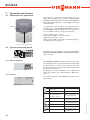
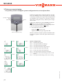
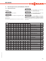
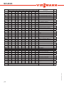
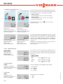
SCU224 49006430 *49006430* SCU224 Mounting Connection Handling Fault indication Examples manual Thanks for buying this product. Read this manual carefully to get the best perfomance from this unit. SCU224 Contents Imprint Safety regulations.................................................................2 Technical data and overview of functions .........................3 1. Installation..............................................................4 1.1 Mounting................................................................................... 4 1.2 Electrical Connection............................................................ 4 1.2.1 Data communication / Bus............................................. 5 1.2.2 Standard solar system............................................................ 5 1.2.3 Solar system and heat exchange......................................... 6 1.2.4 Solar system and afterheating.............................................. 6 1.2.5 Solar system and tank charge in layers.............................. 7 1.2.6 2-tank-solar system valve logic............................................ 7 1.2.7 2-tank-Solar system pump logic.......................................... 8 1.2.8 Solar system with 2 collectors............................................ 8 1.2.9 Solar system afterheating by solid fuel boiler.................. 9 1.2.10 Solar system with heating circuit return flow incr.......... 9 2. Operation and function.......................................10 Safety regulations: Please read the following information carefully before installing and operating the controller. In this way damage to the solar system by wrong installation will be avoided. Please observe that the mounting is adapted to the characteristics of the building, that the local regulations are respected and is conform with the technical rules. CU 72060171 01 UL 60730-1A:2002 CSA E60730.1:2002 C US 2.1 Adjustment buttons............................................................. 10 2.2 System monitoring display.................................................. 10 2.2.1 Channel indication................................................................ 10 2.2.2 Tool bar................................................................................... 10 2.2.3 System screen........................................................................ 11 2.3 Blinking codes........................................................................ 11 2.3.1 System-Screen Blinking codes............................................ 11 2.3.2 LED blinking codes............................................................... 11 3. Primary commissioning.......................................12 4. Control parameter and display channels...........13 4.1 Channel overview................................................................. 13 4.1.1-6 Indication channels............................................................... 15 4.1.6-21 Adjustment channels............................................................ 16 5. Tips for fault indication........................................21 5.1 6. Various..................................................22 Accessory..............................................................24 Reprinting / copying This mounting- and operation manual including all parts is copyrighted. Another use outside the copyright requires the approval of Viessmann Manufacturing Company Inc..This especially applies for copies, translations, micro films and the storage into electronic systems. Editor: Viessmann Manufacturing Company Inc.. Important notice: We took a lot of care over the texts and drawings of this manual and to the best of our knowledge and consent. As faults can never be excluded, please note: Your own calculations and plans under consideration of the current norms and DIN-directions should only be basis for your projects. We don´t offer a guarantee for the completeness of the drawings and texts of this manual - they only represent some examples. They can only be used on own risk. No liability is assumed for incorrect, incomplete or false information and the resulting damages. © 08284 SCU224.monus.indd Errors an technical changes excepted. |2 SCU224 • System-monitoring-display • Up to 4 temperature sensors Pt1000 • 9 basic systems selectable • Heat balancing • VBus® • Function control • Thermostat function (time controlled) • Parameterisation and control of the system by Service Center; Software is possible • User-friendly operation by simple handling ! • Housing in outstanding design and compact dimensions, easy to install Scope of delivery: 1 x SCU224 1 x accessory bag 1 x spare fuse T4A 2 x screws and dowels 4 x strain relief and screws © 08284 SCU224.monus.indd Additionally enclosed in the full kit: 2 x sensor FKP6 2 x sensor FRP6 Technical data Housing: plastic, PC-ABS and PMMA Protection type: IP 20 / DIN 40050 Ambient temp.: 32 ... 104 °F Size: 172 x 110 x 46 mm Mounting: wall mounting, mounting into patch-panels is possible Display: System screen for system visualisation, 16-segment display, 7-segment display, 8 symbols for system status and operating control lamp Operation: by 3 pushbuttons in the front of the housing Functions: Differential temperature controller with optional add-on system functions. Operating hours counter for solar pump, tube collector special function, thermostat function and heat quantity balancing. Inputs: for 4 temperature sensors Pt1000 Outputs: 2 electromechanical relays Bus: VBus® Power supply: 115 V~ Total power supply: 4 (2) A 115V~ 3| SCU224 1. Installation Warning! Switch-off power supply before opening the housing. 1.1 Mounting display pushbutton cover cable conduits with strain relief can fuse 4A fastening The unit must only be located internally. It is not suitable for installation in hazardous locations and should not be sited near to any electromagnetic field.The controller must additionally be equipped with an all-polar gap of at least 3 mm or with a gap according to the valid installaton regulations, e.g. LS-switches or fuses. Please ensure sensor cables and AC power supply are separated. 1. Unscrew the cross-recessed screw of the cover and remove it from the housing. 2. Mark the upper fastening point on the wall and premount the enclosed plug and screw. 3. Hang up the housing at the upper fastening point and mark the lower fastening point on the subsurface (hole depth 1/2"). Install the plug in the lower hole. 4. Fasten the housing at the top and attach it with the lower fastening screw. fixing T4A DE - 45527 Hattingen DeltaSol BS Plus 115 V~ CU 72060171 01 UL 60730-1A:2002 CSA E60730.1:2002 Temp. Sensor Pt1000 S1 1 2 3 S2 4 fuse S3 5 S4 6 7 Sensor connections VBus ® 8 VBus 9 10 12 13 14 R1 2 (1) A 115 V~ R2 2 (1) A 115 V~ N R2 N R1 N L 15 16 17 18 19 20 ground connections Relay connections power connections Dangerous voltage on contact! Electrostatic discharge can lead to damages of electronic components! |4 The power supply to the controller must only be made by an external power supply switch (last step of installation!) and the line voltage must be 115 Volt (60 Hz). Flexible lines are to be fixed at the housing by enclosed strain relief supports and screws. The version the controller is equipped with 2 output relays to which the consumers e.g. pumps, valves etc. can be connected: • Relay 1 18 = line power conductor R1 17 = neutral conductor N 13 = ground clamp • Relay 2 16 = line power conductor R2 15 = neutral conductor N 14 = ground clamp The temperature sensors (S1 up to S4) will be connected to the following terminals independently of the polarity: 1 / 2 = Sensor 1 (e.g. Sensor collector 1) 3 / 4 = Sensor 2 (e.g. Sensor tank 1) 5 / 6 = Sensor 3 (e.g. Sensor collector 2) 7 / 8 = Sensor 4 (e.g. Sensor tank 2) The 115V power supply is connected to: 19 = neutral conductor N 20 = conductor L 12 = ground clamp © 08284 SCU224.monus.indd 1.2 Electrical connection SCU224 1.2.1 Data communication/ Bus DE - 45527 Hattingen DeltaSol BS Plus CU 72060171 01 UL 60730-1A:2002 CSA E60730.1:2002 Temp. Sensor Pt1000 S1 1 2 3 S2 4 S3 5 6 S4 7 8 VBus 9 10 12 13 14 T4A 115 V~ R1 2 (1) A 115 V~ R2 2 (1) A 115 V~ The controller comes with a VBus® for data communication and energy supply of external modules. The modules are connected independently of the polarity to the connections marked with „VBus®“.Via this data Bus you can install one or more VBus® modules, e.g.: N R2 N R1 N L 15 16 17 18 19 20 • heat quant. measurement module WMZ VBus connection terminals • large display GA3 • data logger, DL2 • smart Display SD3 Additionaly, the controller can be connected to the PC with the help of a USB Adaptor cable. With the Service Center Software (RCS) the controller parameters can be changed, measurements can be read out, processed and visualised. The software enables an easy function control and adjustment of the system. Standard solar system with 1 tank, 1 pump and 3 sensors. Sensor S4 / TRF can optionally be used for heat quantity balancing. 1.2.2 Wiring connections for system 1 Arr 1 S1 R1 © 08284 SCU224.monus.indd S3 S4 / TRF S2 Symbol S1 S2 S3 S4 / TRF R1 Specification Collector sensor Tank sensor below Tank sensor at the top (optionally) Sensor for heat quantity measurement (optionally) Solar pump 5| SCU224 1.2.3 Wiring connections for system 2 Solar system and heat exchange with an existing tank with 1 tank, 4 sensors and 2 pumps. Arr 2 S1 R1 S3 Tank 1 Tank 2 S4 S2 R2 1.2.4 Wiring connections for system 3 Symbol S1 S2 S3 S4 R1 R2 Specification Collector sensor Tank sensor lower Tank sensor at the top Tank Sensor 2 Solar pump Pump for heat exchange Solar system and after-heating with 1 tank, 3 sensors and after-heating. Sensor S4 / TRF can optionally be used for heat quantity balancing. Arr 3 R1 S4 / TRF S3 S2 R2 Symbol S1 S2 S3 S4 / TRF R1 R2 |6 Specification Collector sensor Tank sensor lower Tank sensor at the top Sensor for heat quantity balancing (optional) Solar pump Pump for heat exchange © 08284 SCU224.monus.indd S1 SCU224 Solar system and tank charge in layers with 1 tank, 3 sensors, 1 solar pump and 3-way-valve for tank charge in layers. Sensor S4 / TRF can optionally be used for heat quantity balancing. 1.2.5 Wiring connections for system 4 Arr 4 S1 R1 Symbol S1 S2 S3 S4 / TRF S3 R2 S2 S4 / TRF R1 R2 1.2.6 Wiring connections for system 5 Specification Collector sensor Tank sensor lower Tank sensor at the top Sensor for heat quantity balancing (optionally) Solar pump 3-way-valve 2-tank-solar system with valve logic with 2 tanks, 3 sensors, 1 solar pump and 1 3-way-valve. Sensor S4 / TRF can optionally be used for heat quantity balancing. Arr 5 S1 R2 R1 Tank 1 Tank 2 © 08284 SCU224.monus.indd S2 S4 / TRF S3 Symbol S1 S2 S3 S4 / TRF R1 R2 Specification Collector sensor Tank sensor 1 Tank sensor 2 Sensor for heat quantity balancing (optionally) Solar pump 3-way-valve 7| SCU224 2-tank-solar system with pump logic with 2 tanks, 3 sensors and 2 solar pumps. 1.2.6 Wiring connections for system 6 Arr 6 S1 S4 Tank 1 R1 Tank 2 S2 R2 S3 Symbol S1 S2 S3 S4 R1 R2 1.2.7Wiring connections for system 7 Specification Collector sensor Tank sensor 1 Tank sensor 2 Measuring sensor (optional) Solar pump 1 Solar pump 2 Solar system with east-west collectors, 1 tank, 3 sensors and 2 solar pumps. Arr 7 R1 S3 R2 S2 Symbol S1 S2 S3 S4 R1 R2 |8 Specification Collector sensor Tank sensor 1 Collector sensor 2 Measuring sensor (optional) Solar pump collector 1 Solar pump collector 2 © 08284 SCU224.monus.indd S1 SCU224 Solar system with after-heating by solid fuel boiler with 1 tank, 4 sensors, 1 solar pump and 1 pump for afterheating. 1.2.8 Wiring connections for system 8 Arr 8 S1 S4 S3 R1 S2 1.2.9 Wiring connections for system 9 Symbol S1 S2 S3 S4 R1 R2 R2 Specification Collector sensor Lower tank sensor Upper tank sensor Tank for solid fuel boiler Solar pump Pump for solid hot fuel boiler Solar system and heating circuit reverse raising with 1 tank, 4 sensors, 1 solar pump and 1 3-way-valve for heating circuit reverse raising. Arr 9 S1 R1 S4 S3 © 08284 SCU224.monus.indd S2 R2 Symbol Specification S1 Collector sensor S2 Lower tank sensor S3 Upper tank sensor S4 Heating circuit return R1 Solar pump R2 3-way-valve 9| SCU224 2. Operation and function 2.1 Pushbuttons for adjustment backward forward – OK + The controller is operated by 3 pushbuttons below the display. The forward-key (+) is used for scrolling forward through the indication menu or to increase the adjustment values. The backwards-key (–) is accordingly used for the reverse function. For adjustment of last indication channel, keep button + pressed for 2 seconds. If an adjustment value is shown on the display, SEt is indicated. In this case you can press the key „Set“ (OK) in order to change into input mode. Select a channel by keys – and + Shortly press key OK, so that „SEt“ flashes Adjust the value by keys – and + Shortly press key OK, so that „SEt“ permanently appears, the adjusted value is now saved. SET (selection / adjustment mode) 2.2 System monitoring display ! The system monitoring display consists of 3 blocks: indication of the channel, tool bar and system screen (active system scheme). Full Monitoring-Display 2.2.1 Channel indication indication channel only 2.2.2 Tool bar The indication channel consists of two lines. The upper line is an alphanumeric 16-segment indication in which mainly the channel names / menu items are shown. In the lower 7-segment indication, the channel values and the adjustment parameters are indicated. Temperatures are either indicated in °F or °C, whereas temperature differences are indicated in K or °Ra respectively. The additional symbols of the tool bar indicate the current system status. tool bar only Symbol standard blinking relay 1 active relay 2 active antifreeze- function activated collector cooling function or recooling function active collector minimum limitation or antifreeze function active collector security shutdown or tank securtiy shutdown active + sensor defect + manual operation active an adjustment channel is changed SET-mode | 10 © 08284 SCU224.monus.indd maximum tank limitation active / maximum tank temperature exceeded SCU224 2.2.3 System screen The system screen (active system scheme) shows the schemes selected on the controller. It consists of several system component symbols, which are - depending on the current status of the system - either flashing, permanently shown or hidden. System Screen only Sensors upper sensor tank Collector 2 Heating circuit Collector 1 Valve Valve Pumps Sensor Additional symbol for operation of the burner Tank heat-exchanger Tank Tank 2 or afterheating (with an additional symbol) Temperature sensor Collectors with collector sensor Heating circuit Tanks 1 and 2 with heat-exchanger Pump 3-way-valve The flow direction or the current breaking capacity is always shown. Afterheating with burner symbol 2.3 Blinking codes © 08284 SCU224.monus.indd 2.3.1 System screen blinking codes 2.3.2 LED blinking codes • Pumps are blinking during starting phase • Sensors are blinking if the respective sensor-indication channel is selected. • Sensors are quickly blinking in case of sensor defect. • Burner symbol is blinking if after-heating is activated Constantly green: Red/green blinking: Red blinking: everything all right initialisation phase manual operation sensor defect (sensor symbol is quickly blinking) 11 | SCU224 3.Primary commissioning For primary commissioning the system configuration has to be adjusted first operating control lamp forward backward – OK + 1. AC power supply must be activated at first.The controller passes an initialisation phase during which the operating control lamp is blinking red and green. After having finished the initialisation, the controller is in automatic operation with factory settings. The factory default system configuration is Arr 1. 2. Clock time adjustment in channel TIME. By pressing the button once you can adjust hours, pressing it once again the minutes.The time can be adjusted by buttons + and - and saved by pressing the button. 3. - select adjustment channel Arr - change into - adjustment are saved by pressing button SET SET (selection / adjustment mode) Arr 1 -mode (see 2.1) Now the controller is ready for operation and should enable an optimum operation of the solar system with the factory settings. Arr 2 Arr 3 Arr 4 Arr 5 Arr 6 Arr 7 Arr 8 System configurations: Arr 1 : Arr 2 : Arr 3 : Arr 4 : Arr 5 : Arr 6 : Arr 7 : Arr 8 : Arr 9 : standard solar system solar system with heat exchange solar system with after-heating solar system with tank charge in layers 2-tank solar system with valve logic 2-tank solar system with pump logic solar system with 2 collectors and 1 tank solar system with after-heating by solid hot fuel boilers solar system with heating circuit reverse raising © 08284 SCU224.monus.indd Arr 9 | 12 SCU224 4. Control parameter and indication channels 4.1 Channel-overview Corresponding channel is only available if the option heat quantity measurement is activated (OHQM). Legend: x Corresponding channel is available. x* Corresponding channel is available if the appropriate option is activated. COL COL 1 TST TSTU TST1 TSTO TST2 TFSB TRET COL2 S3 TRF S4 hP h P1 h P2 kWh MWh time Arr DT O DT1O DT F DT1F 2 x 3 x 4 x Arr 5 x 6 x 7 8 x 9 x x x x x x x x x x x x x x x x x x x x x x x x x x x x x x x x x x x x x x x x x x x x x x x x x x x x x x x x x x x 1-9 x x x x x x x x x x x x x x x x x x x x x x x x x x Specification Page Temperature collector 1 Temperature collector 1 Temperature tank 1 Temperature tank 1 below Temperature tank 1 below Temperature tank 1 at the top Temperature tank 2 below Temperature solid hot fuel boiler Temperature heating circuit Temperature collector 2 Temperature sensor 3 Temperature return sensor Temperature sensor 4 Operating hours relay 1 Operating hours relay 1 Operating hours relay 2 Heat quantity kWh Heat quantity MWh Time System Switch-on temperature diff Switch-on temperature diff 1 Switch-off temperature diff 1 Switch-off temperature difference 15 15 15 15 15 15 15 15 15 15 15 15 15 16 16 16 16 16 15 12 17 17 17 17 Maximum temperature tank 1 Maximum temperature tank 1 Switch-on temperature difference 2 Switch-off temperature difference 2 Maximum temperature tank 2 emergency temperature collector 1 emergency temperature collector 1 17 17 17 17 17 18 18 © 08284 SCU224.monus.indd S MX S1 MX DT2O DT2F S2MX EM EM1 1 x MEDT The channel antifreeze content (MED%) is only shown if the antifreeze is not water or Tyfocor LS / G-LS (MEDT 0 or 3). Adjustments concerning the antifreeze content will only make sense if the antifreeze is used in the solar circuit. Please note: S3 and S4 are only indicated in case of sensors connected Channnel Corresponding channel is only available if the option heat quantity measurement is deactivated (OHQM). 13 | SCU224 Channel OCX OCX1 CMX CMX1 OKN OKN1 CMN CMN1 OCF OCF1 CFR CFR1 EM2 OCX2 KMX2 OCN2 CMN2 OCF2 CFR2 PRIO tST tRUN OREC O TC DT3O DT3F MX3O MX3F MN3O MN3F AH O AH F OHQM FMAX MEDT MED% t1 on t1 off t2 on t2 off t3 on t3 off HND1 HND2 LANG UNIT PROG 2 x 3 x 4 x Arr 5 x 6 x 7 8 x 9 x x* x* x x x* x* x x x* x* x x* x* x* x* x* x* x* x x x x x x x x* x* x* x* x* x* x* x x x x x x x x* x* x* x* x* x* x* x x x* x x* x x* x x x x x x x x x x x MEDT x x x x x x x x x x x x x MEDT x x x x x x x x x x x x x x x x x x x x x MEDT x MEDT x x x x x x x x XX.XX X.XX x x x x x x x x x x x x x x x x x x x x x x x x x x x x x x x x x Specification option collector cooling collector 1 option collector cooling collector 1 maximum temperature collector 1 maximum temperature collector 1 option minimum limitation collector 1 option minimum limitation collector 1 minimun temperature collector 1 minimun temperature collector 1 option antifreeze collector 1 option antifreeze collector 1 antifreeze temperature collector 1 antifreeze temperature collector 1 emergency temperature collector 2 option collector cooling collector 2 maximum temperature collector 2 option miminum limitation collector 2 minium temperature collector 2 option antifreeze collector 2 antifreeze temperature collector 2 priority stop time Ciruclation time option reccoling option tube collector switch-on temperature difference 3 switch-off temperature difference 3 switch-on treshold for maximum temp. switch-off treshold for maximum temp. switch-on treshold for minimum temp. switch-off treshold for minimum temp. switch-on temp. for thermostat 1 switch-off temp. for thermostat 1 option WMZ maximum flow antifreeze type antifreeze content Switch on time 1 thermostat Switch off time 1 thermostat Switch on time 2 thermostat Switch off time 2 thermostat Switch on time 3 thermostat Switch off time 3 thermostat manual operation relay 1 manual operation relay 2 Language Change over °FAH / °CEL program number Page 18 18 18 18 18 18 18 18 18 18 18 18 18 18 18 18 18 18 18 19 19 19 19 19 17 17 17 17 17 17 20 20 16 16 16 16 20 20 20 20 20 20 20 20 20 20 version number © 08284 SCU224.monus.indd VERS 1 x | 14 SCU224 4.1.1 Indication of collector temperatures COL, COL1, COL2: Collector temperature display range: -40 ... +480°F Shows the current collector temperature. • COL : collector temperature (1-collector-system) • COL1: collector temperature 1 • COL2: collector temperature 2 4.1.2 Indication of tank temperatures TST,TSTL,TSTU, TST1,TST2: Tank temperatures Display range: -40 ... +480 °F Shows the current tank temperature. • • • • • TST : tank temperature (1-tank-system) TSTL : tank temperature lower TSTU: tank temperature above TST1 : temperature tank 1 TST2 : temperature tank 2 4.1.3 Indication of sensor 3 and sensor 4 S3, S4: S3, S4: Sensor temperatures Display range: -40 ... +480 °F Shows the current temperature of the corresponding additional sensor (without control function). • S3 : temperature sensor 3 • S4 : temperature sensor 4 Please note: S3 and S4 are only shown if the temperature sensors are connected. 4.1.4 Indication of other temperatures TFSB,TRET,TRF: other measured temperatures Display range: -40 ... +480 °F Shows the current temperature of the corresponding sensor. • TFSB : temperature solid fuel boiler • TRET: temperature heating reverse raising • TRF : temperature return flow 4.1.5 Time © 08284 SCU224.monus.indd In this channel the current time is indicated. By pressing button SET (OK) for 2 seconds the hours, by pressing it again the minutes are displayed blinking.The time can be set by buttons + and - and saved by pressing the SET (OK) button. 15 | SCU224 4.1.6Operating hours counter h P / h P1 / h P2: operating hours counter Indication channel The operating hours counter adds up the solar operating hours of the respective relay (h P / h P1 / hP2). Full hours are shown on the display. The operating hours added up can be reset. As soon as in one operating hours channel is selected, the symbol permanently shown on the display. The button SET (OK) must pressed for approx. 2 seconds in order to get back into the RESET-mode of the counter.The display-symbol is flashing and the operating hours will be set to 0. In order to finish the RESET-procedure, the button SET (OK) must be pressed in order to confirm. In order to interrupt the RESET-procedure, no button should be pressed for about 5 seconds. The controller returns automatically into the indicaton mode. 4.1.7Heat quantity balancing OHQM:Heat quantity measurement Adjustment range: OFF ... ON Factory setting: OFF A heat quantity balancing is possible for the basic systems (Arr) 1, 3, 4 and 5 in conjunction with a flowmeter. You just have to activate the option heat quantity balancing in channel OHQM. FMAX: Volume flow in l/min Adjustment range 0 ... 20 in steps of 0,1 Factory setting 6,0 The volume flow readable at the flowmeter (l/min) must be adjusted in the channel FMAX. Antifreeze type and concentration of the heat transfer medium are indicated on channels MEDT and MED%. MED%: Concentration of antifreeze in (Vol-) % MED% is blinded out by MEDT 0 and 3. Adjustement range 20 ... 70 Factory setting 45 kWh/MWh:Heat quantity in kWh / MWh Display channel Note: When using Tyfocor HTL antifreeze set the Type to the 1 (propylene glycol), and set the concentration to 50% The heat quantity transported is measured by the indication of the volume flow and the reference sensor of feed flow S1 and return flow S4. It is shown in kWh-parts in the indication channel kWh and in MWh-parts in the indication channel MWh. The sum of both channels form the total heat output. The heat quantity added up can be reset. As soon as one of the display channels of the heat quantity is selected, the symbol is permanently shown on the display.The button SET (OK) must be pressed for approx. 2 seconds in order to get back into the RESET-mode of the counter. The displayis flashing and the value for heat quantity will be symbol set to 0. In order to finish the RESET-procedure, the button SET (OK) must be pressed for confirmation. In order to interrupt the RESET-procedure, no button should be pressed for about 5 seconds. The controller returns automatically into indication mode. | 16 © 08284 SCU224.monus.indd MEDT: antifreeze Adjustment range 0 ... 3 Factory setting 1 Type of antifreeze: 0 : water 1 : propylene glycol 2 : ethylene glycol 3 : Tyfocor® LS / G-LS SCU224 4.1.8 ∆T-regulation DT O: Switch-on temperature difference Adjustment range 2,0 ... 40,0 °Ra Factory setting 12.0 Primarily the controller looks at the temperature difference between the collector temperature sensor and the tank temperature sensor. If the switch-on temperature difference (DT O / DT1O / DT2O) is reached, the pump is activated. If the adjusted switch-off temperature is underrun (DTF / DT1F / DT2F), the controller switches-off. DT F / DT1F / DT2F / DT3F: Switch-off temperature difference Adjustment range 1,0 ...38,0°Ra Factory setting 8,0°Ra Please note: Switch-on temperature difference DT O must be at least 2 °Ra higher than the switch-off temperature difference DF. 4.1.9 Tank maximum temperature S MX / S1MX / S2MX: Maximum tank temp. Adjustment range 40 ... 203 °F Factory setting 140 °F If the adjusted maximum tank temperature is exceeded, further heating of the tank is stopped so that damaging overheating can be avoided. If the maximum tank temperature is exceeded, the display will show the symbol . Please note: The controller is equipped with a securityswitch-off of the tank, which avoids further heating of the tank if 203 °F is reached at the tank. 4.1.10 ∆T-controller (solid fuel boiler and heat exchange) Maximum temperature limitation © 08284 SCU224.monus.indd MX3O / MX3F: Maximum temperature limitation Adjustment range 30 ...205°F Factory setting MX3O 140°F MX3F 136°F Minimum temperature limitation MN3O / MN3F: Minimum temperature limitation Adjustment range 30 ...195°F Factory setting: Arr = 2 MN3O 40°F MN3F 50F Arr = 8 MN3O 140°F MN3F 150°F The controller is equipped with an independent tempe rature differential regulation for which minimum and maximum temperature limations as well as corresponding switch-on and -off temperatures can be separately adjusted. Only possible for Arr = 2 and 8 (e.g. for solid fuel boilers or heat exchange regulation). If the adjusted value MX3O is exceeded, relay 2 will be deactivated. When falling below MX3F, the relay will be switched on again. Reference sensor: S3 by Arr 8 (TSTU) S4 by Arr 2 (TST2) Is the adjusted value MN3O underrun, relay 2 will be deactivated. By falling below MN3F, the relay will be switched on again. Reference sensor: S4 by Arr 8 (TFSB) S3 by Arr 2 (TSTU) Both switch on- and switch off temperature differences DT3F and DT3O apply parallely for the maximal- and minimal temperature limit. 17 | SCU224 4.1.11 Collector temperature limitation Emergency shut down of the collector EM / EM1 / EM2: temperature limitation corector Adjustment range 230 ...400°F Factory setting 285°F 4.1.12System cooling OCX / OCX1 / OCX2: Option System cooling Adjustment range OFF ...ON Factory setting ON CMX / CMX1 / CMX2: collectormaximum temperature Adjustment range 210 ...380°F Factory setting 250°F If the adjusted collector limit temperature (EM / EM1 / EM2) is exceeded the solar pump (R1/R2) is deactivated in order to avoid a damaging overheating of the solar components (collector emergency shutdown). The factory setting for the temperature limitation is 285°F - it can be changed within the adjustment range of 230 ... 400°F. Symbol is shown on the display (blinking). If the adjusted maximum tank temperature is reached, the solar system switches-off. If now the collector temperature rises to the adjusted maximum collector temperature (CMX / CMX1 / CMX2), the solar pump remains activated until this temperature limitation value is again underrun. The tank temperature might continue to rise (subordinated active maximum tank temperature), but only up to 203°F (emergency shutdown of the tank). If the tank temperature is higher than the maximum tank temperature (S MX / S1MX / S2MX) and the collector temperature is by at least 10°RA lower than the tank temperature, the solar pump is activated until the tank is cooled down again by the collector and the tubes below the adjusted maximum temperature (S MX / S1MX / S2MX)(only by activated OREC function). is shown on the display In case of an activated system (blinking). Due to the cooling function, the solar system can be kept operable for a longer period on hot summer days and a thermal release of the collector and the heat transfer medium is ensured as well. 4.1.13Option collector minimum limitation OCN / OCN1 / OCN2: collector minimum limitation OFF / ON Factory setting OFF CMN / CMN1 / CMN2: col. minimum temperature Adjustment range 50 ...195°F Factory setting 50°F The minimum collector temperature is a minimum switching temperature which must be exceeded so that the solar pump (R1/R2) is switched-on. The minimum temperature shall avoid a steady starting-up of the solar pump (or solid fuel boiler charging pumps) for low collector temperatures. If the minimum temperature is underrun, is shown on the display (blinking). OCF / OCF1 / OCF2: antifreeze function Adjustment range OFF / ON Factory setting OFF CFR / CFR1 / CFR2: antifreeze temperature Adjustment range 15 ...50°F Factory setting 40°F | 18 The antifreeze function activates the loading circuit between collector and tank if the adjusted antifreeze function is underrun in order to protect the medium against freezing or „thickening“. If the adjusted frost protection temperature is exceeded by 2°F, the loading circuit will be deactivated. Please note: As there is only a limited quantity of heat available in the tank for this function, the antifreeze function should only be used in regions with few days of temperatures around freezing point. © 08284 SCU224.monus.indd 4.1.14Option antifreeze SCU224 4.1.15 Oscillating charge Respective adjustment values: Factory setting Adjustment range priority [PRIO] (1 / Arr 5,6) (2 / Arr 4) 0-2 oscillating break-time [tST] oscillating charge-time [tRUN] 2 min. 15 min. 1-30 min. 1-30 min. The SCU224 priority logic The above-mentioned options and parameters only have a meaning in multi-tank systems (system Arr = 4, 5, 6). If priority 0 is adjusted, the tanks which show a temperature difference towards the collector are loaded in numerical order (tank 1 or tank 2). Usually only one tank is loaded at this point. For Arr= 5, 6 parallel loading is also possible. priority: Oscillating break time / oscillating charge time / collector rising temperature 4.1.16 Recooling function OREC: option recooling adjustment rangeOFF ... ON Factory setting: OFF 4.1.17 Tube collector special function © 08284 SCU224.monus.indd O TC: Tube collector special function Adjustment range: OFF ... ON Factory setting: OFF The controller checks the tanks regarding loading facilities (switch-on difference). If the priority tank cannot be loaded, the lower-ranking tank is checked. If the lower-ranking tank can be charged this is effected by the so-called „oscilating charge time“ (tRUN).When the oscillating charge time is over the loading is stopped. The controller regulates the increase of the collector temperature. If it increases by the collector rising temperature (∆T-Col 4°Ra, fixed software value), the expired break time is again reset to zero and the oscillating break time starts again. If the switch-on conditions of the priority tank are not reached, the loading of the lower-ranking tank is continued. If the priority switch has reached its maximum temperature, the oscillating charge is not effected. If the adjustem maximum tank temperaute (S MX, S1MX, S2MX) is reached, the solar pump remains activated in order to avoid an overheating of the collector. The tank temperature might continue to increase but only up to 203 °F (emergency shutdown of the tank). In the evening the solar system continues running until the tank is cooled down to the adjusted maximum tank temperature via collector and pipes. If the controller measures an increase of 4°Ra compared to the last collector temperature stored, the solar pump is switched-on to 100 % for about 30 seconds. After the expiration of the solar pump runtime the current collector temperature is stored as a new reference value. If the measured temperature (new reference value) is again exceeded by 4°Ra, the solar pump again switches-on for 30 seconds. If the switch-on difference between collector and tank is again exceeded during the runtime of the solar pump or during standby mode of the system, the controller automatically switches over to solar charging. If the collector temperature drops by 4°Ra during standby, the switch-on value for the special tube collector function will be recalculated. 19 | SCU224 4.1.18 Thermostat function (Arr = 3) Afterheating use of surplus energy The thermostat function works independently from the solar pump operation and can be used for after-heating by a boiler, use of surplus energy, or for rejecting excess heat. • AH O< AH F the thermostat function is used for after-heating • AH O> AH F the thermostat function is used for use of surplus energy or heat rejection. The display shows the symbol output is activated. AH O: Thermostat- switch-on temperature Adjustment range 30 ...205°F Factory setting 105°F t1 E, t2 E, t3 E: Thermostat switch-on time Adjustment range: 00:00 ... 23:45 Factory setting: 00:00 if the second relay AH F: Thermostat- switch-off temperature Adjustment range 30 ...205°F Factory setting 115°F t1 A, t2 A, t3 A: Thermostat switch-off time Adjustment range: 00:00 ... 23:45 Factory setting: 00:00 In order to block the thermostat function for a certain time span, there are 3 time frames t1 ... t3. If the function should be activated only between e.g. 6:00 and 9:00, 6:00 should be set for t1 E and 9:00 should be set for t1 A. The factory setting for the thermostat function is in continuous operation. If all time frames should stop at 00:00 o’ clock, the thermostat function is continuously in operation (factory setting). 4.1.19 Operating mode HND1/HND2: Operating mode Adjustment range: OFF, AUTO, ON Factory setting: AUTO For control- and service works the operating mode of the controller can be manually adjusted by selecting the adjustment value MM in which the following adjustments can be made: • HND1 / HND2 Operating mode OFF : AUTO : ON : relay off (blinking) + relay in automatic operation relay on (blinking) + 4.1.20 Language The menu language can be adjusted in this channel. • • • • dE : German En : English It : Italiano Fr : French 4.1.21 Unit UNIT: Adjustment of unit Adjustment range: FAH, °C Factory setting: FAH | 20 The menu unit can be adjusted: • °FAH • °CEL © 08284 SCU224.monus.indd LANG: Adjustment of language Adjustment range: dE, En, It, Fr Factory setting: En SCU224 5.Tips for fault indication If a malfunction occurs, it will be indicated on the display of the controller: can fuse 4A T4A DE - 45527 Hattingen DeltaSol BS Plus 115 V~ CU 72060171 01 UL 60730-1A:2002 CSA E60730.1:2002 Temp. Sensor Pt1000 S1 1 2 3 S2 4 S3 5 6 S4 7 8 VBus 9 10 R1 2 (1) A 115 V~ R2 2 (1) A 115 V~ 12 13 14 Warning symbol N R2 N R1 N L 15 16 17 18 19 20 Operating control lamp Operating control lamp flashes red. On the display the and appear. symbols Sensor defect. An error code is shown on the relevant sensor indication channel instead of a temperature. 888.8 - 88.8 Line break. Check the line. Short-circuit. Check the line. Operating control lamp off Check the power supply o.k. The can fuse of the controller is defective. It can be replaced after removal of the front cover (spare fuse is enclosed in the accessory bag). © 08284 SCU224.monus.indd Pt1000-temperature sensors can be checked with an ohmmeter. The following table lists the corresponding resistance values for different temperatures. °F Ω °F Ω 14 23 32 41 50 59 68 77 86 95 104 113 122 961 980 1000 1019 1039 1058 1078 1097 1117 1136 1155 1175 1194 131 140 149 158 167 176 185 194 203 212 221 230 239 1213 1232 1252 1271 1290 1309 1328 1347 1366 1385 1404 1423 1442 Resistance values of the Pt1000-sensors 21 | SCU224 5.1Various: Pump is overheated, but no heat is being transferred from collector to the tank, feed flow and return flow are equally warm, possibly also bubble in the tubes Pump starts for a short moment, switches-on/off repeatedly Air in the system? Is the temperature difference at the controller too small? no yes Exhaust the system; increase system pressure to the minimum pressures listed in the Vitosol Startup and service manual. Switch the pump on and off for a short time Is the collector circuit blocked at the dirt trap? no Wrong placing of the collector sensor? no yes Clean the dirt trap yes yes Activate option tube collector special function Change ∆T on and ∆T off accordingly. no o.k. Mount the collector sensor at solar feed flow (warmest collector output); use the sensor well of the respective collector. Pump starts up very late and stops working soon. The temperature difference between tank and collector increases enormously during operation; the collector circuit cannot dissipate the heat. Switch-on-temperature difference ∆Ton too large? Collector circuit pump defect ? no yes no Change ∆T on and ∆Toff accordingly. Repair / Replace Heat exchanger calcified? Collector sensor unfavour able placed (e.g. contact sensor instead of sensor well. yes yes no yes Decalification If necessary activate tube collector function. o.k. Heat exchanger plugged? no yes Heat exchanger too small? yes New calculation of the dimension. | 22 © 08284 SCU224.monus.indd Cleaning SCU224 a b Tanks are cooled during the night. Control the check valve in warm water circulation- o.k. Does collector circuit pump run during the night? no yes Collector temperature is at night higher than ambient temperature. no yes yes Check the controller functions Check the supply and return line flow check valves to ensure functionality. Is the tank insulation sufficient? yes no Intensify the insulation. no no Warm water outflow upwards? no yes Does the control LED flash? Insulate connections. Change connection and let the water flow sidewards or through a thermosiphon trap; less tank losses now? no Does warm water recirculation pump run for a very long time? no yes © 08284 SCU224.monus.indd Switch-off the re-circulation pump and the isolation valve for 1 night; less tank losses? yes no yes o.k. Use the re-circulation pump with timer and switch-off thermostat (energy efficient circulation) Check the pumps of the after-heating circuit according to nightly run and defective check valve; problem solved? no a The gravitation circu lation in the circulation line is too strong; insert a stronger check valve or an electrical 2-way valve behind the circulation pump; the 2-way valve is open in pump operation, other wise it is closed, conect pump and 2-way valve in parallel; activate the circulation again! Cleaning or replacement. Replace or intensify the insulation. Are the tank connections insulated? yes no The solar circuit pump does not work although the collector is obviously warmer than the tank. Is the tank insulation close enough to the store? yes Please also check further pumps which are connected to the solar tank. b yes no Does the pump start up in manual operation? no yes Is the power supply to the pump coming from the controller? no yes There is no current; check fuses / replace them and check power supply. The adjusted temperature difference for starting the pump is too high; choose a matching setting Is the pump stuck? yes Put the pump into operation by means of a screwdriver; is it passable now ? no Are the fuses o.k.? no Replace the fuses. Is the pump out of order? - replace if necessary yes Controller seems to be defective - replace it. 23 | SCU224 6. Accessory Smart Display SD3 Serves as a visualization of collector and DHW tank temperature, as well as energy transfer (kWh) within the solar system. Datalogger DL2 Come complete with ServiceCenter Software (full version). Compact wall mounted devise to capture system operational details enabling further anaylsis using ServiceCenter software, or using spreadsheet software. Comes with 180 MB flash memory and ethernet cable connection. ServiceCenter Light Software c/w USB Adaptor Cable Used to view system activities and performance in real time obtained from the Solar Control Unit and it's sensors. ServiceCenter Full Software c/w USB Adaptor Cable Same as above plus datalogger integration and ability to change settings of Solar Control Unit using PC. Viessmann Manufacturing Company (U.S.) Inc. 45 Access Rd. Warwick, RI 02886 Telephone: (401) 732-0667 Fax: (401) 732-0590 Internet: www.viessmann-us.com E-Mail: [email protected] Viessmann Manufacturing Company Inc. 750 McMurray RD. Waterloo, Ontario N2V 2G5 Telephone: (519) 8856300 Fax: (519) 8850887 Internet: www.viessmann.ca E-Mail: [email protected] Please note: The design and the specifications are to be changed without notice. The illustrations may differ from original product. | 24 © 08284 SCU224.monus.indd Distributed by: