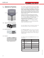
1
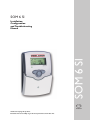
SOM 6 SI SOM 6 SI Installation, Configuration and Troubleshooting Manual manual Thanks for buying this product. Read this manual carefully to get the best perfomance from this unit. SOM 6 SI Contents Imprint .................................................................................2 Security devices ...................................................................2 Technichal data and function survey .................................3 1. Installation .............................................................4 1.1 Mounting .................................................................................. 4 1.2 Electrical wiring ...................................................................... 4 1.2.1 Standard solar system ........................................................... 5 2. Operation and function ........................................6 2.1 Adjustment buttons .............................................................. 6 2.2 System monitoring display ................................................... 6 2.2.1 Channel indication ................................................................. 6 2.2.2 Tool bar .................................................................................... 6 2.2.3 System screen ......................................................................... 7 2.3 2.3.1 2.3.2 3. 3.1 3.1.1-6 3.1.7-19 3.2 4. 5. Safety regulations: Please read the following information carefully before installing and operating the controller. When configuring the controller please utilize some semblance of the recommeded settings illustrated in section 3.2. This will avoid damage to the solar system by common problems such as overheating. Installing the controller using the default settings without making any adjustments to the configuration parameters is likely to result in an overheating condition of the solar system at some point. Please ensure that the mounting is in accordance to local, state and federal regulations. Reprinting / copying This installation manual in its entirety is copyrighted. Another use outside the copyright requires the approval of STIEBEL-ELTRON Inc. This especially applies for copies, translations, micro films and the storage into electronic systems. Editor: STIEBEL-ELTRON Inc. Blinkcodes ............................................................................... 7 System-Screen Blinkcodes ................................................... 7 Blinking codes ......................................................................... 7 Control parameter and indication channels ......8 Channel overview .................................................................. 8 Indication channels ................................................................ 9 Adjustment channels ........................................................... 10 Recommended Settings .....................................13 Troubleshooting Tips ...........................................14 Warranty..............................................................17 Important notice: Your own calculations and plans under consideration of the current norms and DIN-directions should only be basis for your projects. We don´t offer a guarantee for the completeness of the drawings and texts of this manual they only represent some examples. They can only be used at your own risk. No liability is assumed for incorrect, incomplete or false information and the resulting damages. . C US © 06184 som_6_si.monen.indd CU 72060171 01 UL 60730-1A:2002 CSA E60730.1:2002 |2 SOM 6 SI • system-monitoring-display • up to 4 temperature sensors Pt1000 • function control • user-friendly operation • solar loop operating hours counter ! Scope of delivery: 1 x SOM 6 SI 1 x accessory bag 1 x spare fuse T4A 2 x screws and dowels 4 x strain relief and screws Additionally enclosed in the full kit: 2 x sensor FKP6 1 x heat conductive paste Functions: Temperature differential controller with optional add-on system funtcions. Function control according to BAW-guidelines, operating hours counter for solar pump and tube collector special function. Inputs: for 3 temperature sensors Pt1000 Outputs: 1 electromechanical relay Power supply: 120 VAC Total power supply: 2 (1) A 120 VAC Mode of operation: Typ 1.b Breaking capacity per relay: electromechanical relay: 2 (1) A 120 VAC © 06184 som_6_si.monen.indd Technical data Housing: plastic, PC-ABS and PMMA Protection type: IP 20 / DIN 40050 Environmental temp.: 32 - 104 °F Size: 172 x 110 x 46 mm Mounting: wall mounting, mounting into patch-panels is possible Display: System screen with graphical illustration, 16-segment display, 7-segment display, 8 symbols for system status and operating control lamp Operation: by 3 pushbuttons in the front of the housing 3| SOM 6 SI 1. Installation display Warning! Switch-off power supply before opening the housing. 1.1 Mounting cover pushbutton cable conduits with strain relief can fuse 4A Upper fastening hole The unit is designed for indoor installation only. It is not suitable for installation in hazardous locations and should not be sited near to any electromagnetic field. The controller must installed in accordance with all electrical regulations. These regulations vary from region to region. Please contact the appropriate agency in your area if unclear on this. Wall Mounting Instructions 1. Unscrew the cross-recessed screw of the cover and remove it from the housing. 2. Mark the upper fastening point on the wall and mount the enclosed dowel and screw. 3. Hang up the housing at the upper fastening point and mark the lower fastening point on the wall. The distance between the 2 mounting holes is 130 mm. 4. Fasten the housing at its lower point.. Lower fastening hole fuse Inc. US-West Hatfield, MA 01088 SOM 6 SI T4A 2 (1) A 115 V~ Temp. Sensor Pt1000 S4 S1 S2 S3 1 2 3 4 5 6 7 8 Sensor clamps 12 13 14 Earth ground N R1 N L 17 18 19 20 Relay output Line voltage input The power supply to the controller must only be made by an external power supply switch and the line voltage must be 120 VAC (50/60 Hz). Flexible lines are to be fixed at the housing by enclosed strain relief supports and screws. The SOM 6 controller is equipped with 1 relay which is usually connected to the solar loop’s circulator pump. • Relay 1 18 = Conductor R1 17 = Neutral conductor N 13 = Earth ground The temperature sensors (S1 to S4) are to be connected to the following terminals (not polarity sensitive): 1 / 2 = Sensor 1 (Collector sensor) 3 / 4 = Sensor 2 (Storage sensor) 5 / 6 = Sensor 3 (For monitoring only) 7 / 8 = Sensor 4 (For monitoring or Energy Production Measurement) The power supply is to be connected to the following terminals: 19 = neutral conductor N 20 = line conductor L 12 = ground terminal Electrostatic discharge can lead to damage to electronic components! Hazardous voltage present! |4 © 06184 som_6_si.monen.indd 1.2 Electrical wiring SOM 6 SI 1.2.1 Allocation of clamps for system 1 Standard solar system with 1 store, 1 pump and 3 sensors.The sensor S4 / TRF can optionally be used for energy production measurement. S1 R1 S3 S4 / TRF S2 Symbol S1 S2 S3 S4 / TRF Solar pump © 06184 som_6_si.monen.indd R1 Specification Collector sensor Lower tank sensor Upper tank sensor (optional) Sensor for energy production measurement (optional) 5| SOM 6 SI 2. Operation and function 2.1 Pushbuttons for adjustment backwards forward 2 3 1 SET (selection / adjustment mode) 2.2 System monitoring display The controller is operated by the 3 keys below the display. To enter the configuration mode toggle through the display parameters by pressing and releasing key 1 until this no longer causes the display to change. At this point press and hold key 1 until the configuration parameters are displayed (about 5 seconds), then quickly release the key to avoid toggling to the end of the parameter list.The first parameter in the list is DT O. To change the setting of a given parameter, follow the steps below. 1. Toggle to the parameter using keys 1 and/or 2. The abbreviation for the parameter is displayed on the right side of the screen, with the setting directly below, and the set icon solid (not blinking) on the extreme right. 2. Press key 3. The set icon begins blinking signifying that the parameter may now be adjusted. 3. Quickly use keys 1 and/or 2 to change the setting to that which is required. 4. Press key 3 again. The set icon stops blinking signifying that the new value has been stored. ! The system display consists of an indication channel, a tool bar, and the system screen. These are detailed below. Monitoring-Display 2.2.1 Indication Channel Indication channel The indication channel consists of two lines. The upper line is an alphanumeric 16-segment display, in which an abbreviation of the current setting or reading is shown. In the lower 7-segment display, the value of said reading or setting is shown. 2.2.2 Tool bar The additional symbols of the tool bar indicate the current system status. Symbol standard flashing relay 1 active Toolbar only illustrated above maximum storage temperature reached or exceeded antifreeze- function activated collector cooling function or reccoling function active collector minimum limitation or antifreeze function active collector security shutdown or store securtiy shutdown active sensor defect + manual operation active © 06184 som_6_si.monen.indd + |6 SOM 6 SI 2.2.3 System screen The system screen (active system scheme) shows the schemes selected on the controller. It consists of several system component symbols, which are - depending on the current status of the system - either flashing, permanently shown or hidden. only system screen Sensor 1 Sensor Collector 1 Pumps Storage tank heat exchanger Storage tank Temperature sensor Collector with collector sensor Pump Store 1 with heat exchanger 2.3 Blinking codes 2.3.1 System screen blinking codes © 06184 som_6_si.monen.indd 2.3.2 LED blinking codes • Pumps are blinking during starting phase • Sensors are blinking when their value is being displayed in the indication channel. • Sensors are quickly blinking in case of sensor defect. Constantly green: Red/green blinking: Red blinking: Normal operation Power-up phase Manual operation Sensor defect (sensor symbol is quickly blinking) 7| SOM 6 SI 3. Controller parameter and indication channels 3.1 Channel-overview Legend: x* Corresponding channel is available if the appropriate option is activated. Please note: S3 and S4 are only indicated if sensors are connected. Corresponding channel is only available if the option energy production measurement is activated (OHQM). Corresponding channel is only available if the option energy production measurement is deactivated (OHQM). MEDT The channel antifreeze content (MED%) is only shown if a medium other than water or propylene glycol is used. The adjustment is only appropriate when using other types of antifreeze. channel specification page COL x Collector Temperature 9 TST x Lower Storage Tank Temperature 9 S3 x Sensor 3 Temperature 9 TRF Return Sensor Temperature 9 S4 Sensor 4 Temperature 9 hP x Operating Hours Counter 9 kWh Energy Production kWh MWh Energy Production MWh DT O x DT F channel specification page OCN x Collector Minimum Temperature Limitation 11 CMN x* Collector Minimum Temperature 11 OCF x Antifreeze Function 11 CFR x* Antifreeze Temperature 11 10 OREC x Recooling Option 12 10 O TC x Tube Collector Function 12 Switch-On Temperature Differential 10 OHQM x Energy Production Measurement 10 x Switch-Off Temperature Differential 10 FMAX Maximum Flow Rate (LPM) 10 S MX x Maximum Storage Tank Temperature 11 FMXG Maximum Flow Rate (GPM) This is only 10 EM x Collector Emergency Shutdown Temperature 11 Antifreeze Type 10 MEDT MED% available on later release levels MEDT Antifreeze Concentration 10 HAND x Circulator Pump Operating Mode 12 LANG x Language 12 UNIT x Temperature Units °FAH / °CEL 12 XX.XX Program Number VERS X.XX Version Number © 06184 som_6_si.monen.indd PROG |8 SOM 6 SI 3.1.1 Collector Temperature COL: Collector Temperature display range: -40 →+482 °F Shows the current collector temperature. • COL : collector temperature 3.1.2 Lower Storage Tank Temperature TST: Store Temperature Display range: -40 →+482 °F Shows the current store temperature. • TST : store temperature 3.1.3 Sensor 3 or 4 S3, S4: Sensor Temperatures Display range: -40 →+482 °F Shows the current temperature of the corresponding additional sensor (without control function). • S3 : sensor 3 temperature • S4 : sensor 4 temperature Please note: S3 and S4 are only indicated if the temperature sensors are connected (shown). 3.1.4 Other Temperatures (if applicable) TRF: Return Flow Temperature Display range: -40 →+482 °F Shows the current temperature of the sensor. • TRF : return flow temperature 3.1.5 Operating Hours Counter h P: Number of hours which relay 1 has been active The operating hours counter adds up the solar operating hours of the relay (h P). The total amount of hours which the relay has been active is shown on the display. The operating hours total can be reset. As soon as the operating hours channel is selected, the symbol is displayed solid.To reset the operating hours press and hold the middle key (key 3) for approximately 5 seconds. The set symbol blinks. Press key 3 again and the operating hours counter is reset to 0. © 06184 som_6_si.monen.indd In order to interrupt the RESET-procedure, don’t press any button for about 5 seconds.The controller returns automatically into the display mode. 9| SOM 6 SI 3.1.6Energy Production Measurement OHQM: Energy Production Measurement. Adjustment range: OFF/ON Factory setting: OFF FMAX: Volumetric flow rate in l/min Adjustment range 0 - 20 in steps of 0.1 Factory setting 6.0 MEDT: Antifreeze Type Adjustment range 0 - 3 Factory setting 1 MED%: Antifreeze Concentration in (Vol-) % MED% is blinded out by MEDT 0 and 3. Adjustment range 20 - 70 Factory setting 45 kWh/MWh:Energy production in kWh / MWh Display channel A measurement of the system’s energy production is possible in conjunction with a flowmeter and an additional sensor which measures the heat exchanger’s return temperature. Activate this option by changing the value of OHQM to “on”. Adjust this setting to the maximum flow rate of the system in liters per minute. This is necessary in order to calculate the system‘s actual energy output. Some controllers have an additional parameter, FMXG, which is the flow rate in gallons per minute. Type of antifreeze: 0 :water 1 :propylene glycol 2 :ethylene glycol 3 :Tyfocor® LS / G-LS The energy produced by the system is measured by the calculation of the volume of heat exchanger fluid moved through the system and a comparison of the temperature of the fluid leaving the collector (S1) with that of the fluid exiting the storage tank‘s heat exchanger (S4). It is shown in kWh in one channel and MWh in another. The total energy produced can be reset. As soon as one of the display channels of the heat quantity is selected, the symbol is displayed solid.To reset the total energy produced press and hold the middle key (key 3) for approximately 5 seconds. The set symbol blinks. Press key 3 again and the total energy produced is reset to 0.. In order to interrupt the RESET-procedure, no button should be pressed for about 5 seconds. The controller returns automatically into indication mode. DT F: Switch-Off Temperature Differential Adjustment range 1.0 - 38.0 °F Factory setting 8.0 °F Please note: Switch-on temperature difference DT O must be at least 2 °F higher than the switch-off temperature difference DT F. | 10 Primarily, the controller works in the same way as a standard differential controller. If the switch-on difference (DT O) is reached, the pump is activated. If the adjusted switch-off temperature is measured (DT F), the controller switches off. © 06184 som_6_si.monen.indd 3.1.7 ∆T-regulation DT O: Switch-On Temperature Differential Adjustment range 2.0 - 40.0 °F Factory setting 12.0 SOM 6 SI 3.1.8 Maximum Store Temperature S MX: Maximum Storage Tank Temperature Adjustment range: 40 - 205 °F Factory setting 140 °F 3.1.9Collector Emergency Shutdown Temperature EM: Collector Emergency Shutdown Temperature Adjustment range 230 - 400 °F, Factory setting 285 °F 3.1.10System Cooling Functions. OCX: System Cooling Adjustment range OFF/ON Factory setting OFF CMX: Maximum Collector Temperature Adjustment range: 210 - 380 °F Factory setting 250 °F If the adjusted maximum temperature is exceeded, a further loading of the store is stopped so that a damaging overheating can be avoided. If the maximum store temperature is exceeded, the symbol is displayed. Please note: The controller is equipped with a securityswitch-off of the storage tank, which will not allow further loading of the tank if it reaches 205 °F. If the collector emergency shutdown temperature (EM) is reached, the solar pump (R1) is deactivated in order to avoid damaging the solar components.The default setting is 285 °F. If the system is in emergency shutdown mode the symbol is flashing. The system will not exit this mode until the temperature measured is 30 °F lower than the value of this setting. The system cooling function is used to prevent the system‘s heat exchanger fluid from overheating.This in turn prevents the degradation of the fluid‘s corrosion inhibitors avoiding damage to the system components. If the system cooling function is activated the symbol is flashing. If the maximum collector temperature is reached the maximum storage tank temperature is overridden and the system‘s circulator pump is turned on, cooling the system‘s HX fluid using the water in the storage tank. This will continue until either the collector temperature is measured to be at least 9 °F lower than the setting of “CMX”, the tank reaches it’s 205 °F security-switch-off temperature, or the collector reaches its collector emergency shutdown temperature.The last two instances should not occur if the system is sized and configured properly. 3.1.11 Minimum Collector Temperature Limit OCN: Collector Minimum Temperature Limitation Adjustment range OFF/ON Factory setting OFF CMN: Collector Minimum Temperature Adjustment range 50 - 195°F Factory setting 50°F The minimum collector temperature is a temperature which must be exceeded in order for the solar pump (R1) to be switched-on. The minimum temperature setting is used to avoid starting-up the solar pump (or solid fuel boiler charging pumps) when the temperature of the heat exchanger fluid is too low. If the minimum temperature feature is activated the symbol is shown on the display (blinking). © 06184 som_6_si.monen.indd 3.1.13Antifreeze Function OCF: Antifreeze Function Adjustment range OFF/ON Factory setting OFF CFR: Antifreeze Temperature Adjustment range 15 -50°F Factory setting 40°F The antifreeze function activates the loading circuit between collector and tank if the antifreeze temperature is reached in order to protect the heat exchanger fluid against freezing or “thickening“. If the antifreeze temperature is exceeded by 2°F, the loading circuit will be deactivated. Please note: As there is only a limited heat quantity of the tank available for this function, the antifreeze function should only be used in regions with few days of temperatures around freezing point. 11 | SOM 6 SI 3.1.13 Recooling Function OREC: Recooling Option adjustment range OFF / ON Factory setting: OFF 3.1.14 Tube Collector Function O TC: Tube Collector Function Adjustment range: OFF / ON Factory setting: OFF This setting is designed to be used in conjunction with the System Cooling Function, which overrides the maximum store temperature (S MX) when used. This function will cool the tank back down to its maximum temperature when the collector temperature becomes low enough to facilitate such.This prevents a cumulative overheating condition if the cooling function needs to be used multiple days in a row. In order to utilize this function with tube collectors, a heat rejection loop (heat dump) is necessary. If the controller measures an increase of 4 °F compared to the collector temperature which was last stored, the solar pump is switched-on for about 30 seconds. After the solar pump is deactivated the current collector temperature is stored as new reference value. If the measured temperature (new reference value) is again exceeded by 4 °F, the solar pump again switches-on for 30 seconds. If the switch-on differential is reached during any of these processes the controller automatically switches over to solar charging. If the collector temperature drops by 4 °F while the system fluid is stagnant, the switch-on value for the special tube collector function will be recalculated. 3.1.15 Circulator Pump Operating Mode HAND: Operating Mode Adjustment range: OFF/AUTO/ON Factory setting: AUTO For control and service work the operating mode of the controller can be manually adjusted by selecting the adjustment value HAND, in which the following settings are available. • HAND Operating mode OFF : relay off (flashing) + AUTO : relay in automatic operation ON : relay on (flashing) + 3.1.16 Language The menu language can be adjusted in this channel. LANGUAGE Language Setting Adjustment range: dE, En, It, Fr Factory setting: En • • • • dE : German En : English It : Italian Fr : French UNIT: Temperature Display Units Adjustment range: FAH, CEL Factory setting: FAH | 12 The menu units can be adjusted in this channel: • °FAH • °CEL © 06184 som_6_si.monen.indd 3.1.17 Units for Temperature Display SOM 6 SI 3.2.1 Recommended Settings for Standard DHW System Display Code Parameter Name and Reference Recommended Setting and Explanation (All temperatures in °F) DT O Switch on Temperature 15° Setting this too low can cause the circulator to cycle on and off too frequently. Difference (p. 10) DT F Switch off Temperature 5° Too high of a ΔT between DT O and DT F can cause the circulator to switch on and off too frequently. Difference (p. 10) S MX EM OCX 140° This will prevent the temperature at the top of the tank from getting hot enough to cause the T & P valve to release. This will also allow the cooling function to operate effectively. Collector Emergency 310° This prevents the HX fluid directly behind that in the Shutdown Temperature sensor well from causing the system to go into emergency (p. 11) shutdown mode as soon as the cooling function is activated. On Failure to change this option to ‘on’ will likely result in System Cooling overheating of the system at some point. Function (p. 11) Maximum Store Temperature (p. 11) CMX Maximum Collector Temperature (p. 11) OCN Minimum Collector Temperature (p. 11) OCF Antifreeze Option (p. 11) OREC Recooling Function (p. 12) O TC Tube Collector Function (p. 12) OHQM Energy Production Measurement (p. 10) HAND LANG 230° Having a relatively large ΔT between CMX and EM prevents the HX fluid directly behind that in the sensor well from causing the system to go into emergency shutdown mode as soon as the cooling function is activated. Off The ΔT between DT O and DT F achieves the requisite effect for most situations. Off Unless the system is located in a region which rarely experiences temperatures near freezing, and a very low glycol to water percentage is being used. On This prevents a cumulative overheating of the system by ensuring a relatively high Δt between the tank temperature and and the security switch-off of the tank (205°). Off Unless the system is utilizing tube collectors. Off Unless the installer has purchased an additional sensor and wished to utilize this function. Auto This is the normal operating mode. The other two Circulator Pump Operating Mode (p. 12) modes are for testing, charging, etc. Language (p. 12) En (English) For most applications in North America this is appropriate, with some exceptions. Units for Temperature FAH For most applications in North America this is appropriate, but it is purely a matter of preference. Display (p. 12) Please note that advanced users may desire to adjust certain parameters differently depending on the circumstances. These suggested settings are merely a manner in which to configure the unit that will avoid damage to the system from overheating. Installing the SOM 6 with the default settings will likely result in an overheating condition of the solar system. © 06184 som_6_si.monen.indd UNIT 13 | SOM 6 SI 4.Troubleshooting tips If a malfunction occurs, a notification is given on the display of the controller: °F Ω °F Ω 14 23 32 41 50 59 68 77 86 95 104 113 122 961 980 1000 1019 1039 1058 1078 1097 1117 1136 1155 1175 1194 131 140 149 158 167 176 185 194 203 212 221 230 239 1213 1232 1252 1271 1290 1309 1328 1347 1366 1385 1404 1423 1442 Resistance values of the Pt1000-sensors Symptom Warning symbol Operating control lamp can fuse T4A Inc. US-West Hatfield, MA 01088 SOM 6 SI T4A 2 (1) A 115 V~ Temp. Sensor Pt1000 S4 S1 S2 S3 1 2 3 4 5 6 7 8 12 13 14 N R1 N L 17 18 19 20 Possible Cause and Remedies List © 06184 som_6_si.monen.indd SOM unit is sensing an open circuit condition. Operating control lamp flashes red. The symbol is displayed and the symbol is flashing. 1. Measure the resistance between the two terminals to which the relevent sensor is attached. If it measures infinite resisThe indication channel of the relevent sensor tance continue to step 2. If it measures a resistance within displays 888.8 instead of the temperature. range of the above chart, call for service. 2. Disconnect the sensor wire from the terminals and measure the resistance between the two wires. If it still measures infinite resistance continue to step 3. If it measures a resistance within range of the above chart, there is a problem with the connection from the sensor wire to the terminal. 3. This problem lies either with the sensor or the wire/connections. In order to determine whether the problem lies with the sensor itself, the sensor must be disconnected from any extension wire and its resistance must be measured. If, when the sensor is disconnected, the resistance is measured to be within the values of the resistance chart the problem is with the extension wire/connections. | 14 SOM 6 SI Symptom Possible Cause and Remedies List SOM unit is sensing a short circuit condition. Operating control lamp flashes red. The symbol is displayed and the symbol is flashing. 1. Measure the resistance between the two terminals to which the relevant sensor is attached. If it measures a resistance The indication channel of the relevent sensor close to zero continue to step 2. If it measures a resistance displays -88.8 instead of the temperature. within range of the above chart, call for service. 2. Disconnect the sensor wire from the terminals and measure the resistance between the two wires. If it still measures a resistance close to zero continue to step 3. If it measures a resistance within range of the above chart, there is a problem with the connection from the sensor wire to the terminal. 3. This problem lies either with the sensor or the wire/connections. In order to determine whether the problem lies with the sensor itself, the sensor and its 4’ wire which was factory installed must be disconnected from any extension wire and its resistance must be measured. If, when the sensor is disconnected, the resistance is measured to be within the values of the resistance chart the problem is with the extension wire/ connections. Operating control lamp is off and screen is blank. SOM unit’s control board is not receiving power. HAZARDOUS VOLTAGE PRESENT! 1. Measure the voltage between terminals 19 and 20. If the voltage is close to the nominal voltage of 120 VAC, continue to step 2. If the voltage is not correct, the problem lies with the power supply to the unit. 2. Remove the unit’s can fuse and measure its resistance. If the resistance is close to zero, call for service. If infinite resistance is measured, replace the fuse. © 06184 som_6_si.monen.indd Collector is much hotter than the storage tank, but the system’s circulator is not on. 1. Compare the tank’s present temperature with its maximum setting (S MX). If the storage tank is within 4 degrees of this setting the circulator pump will not turn on even if the switch on temperature has been reached unless the System Cooling Function (OCX) is turned on and the Maximum Collector Temperature (CMX) has been reached. 2. Check to see if the symbol is blinking. If this is the case the system is in Emergency Shutdown Mode. Either the collector sensor measured a temperature equal to or greater than the Collector Emergency Shutdown Temperature (step 3), or the store sensor measured a temperature of at least 205 °F (step 4). 3. If the system has reached the Collector Emergency Shutdown Temperature, the controller’s configuration needs to be checked. Is the cooling function (OCX) set to on? Is there a sufficiently large ΔT between the Maximum Collector Temperature (CMX) and the Collector Emergency Shutdown Temperature (EM)? To get the system to exit emergency shutdown mode the EM setting must be at least 30 °F greater than the measured collector temperature. 4. If the storage tank has reached its emergency shutdown temperature (205 °F), the circulator will not turn on unless the store sensor measures a temperature of 201 °F or less. This parameter is not adjustable. 15 | SOM 6 SI Symptom LED is blinking red and green. Possible Cause and Remedies List 1. 2. Tank temperature cools excessively overnight. 1. 2. 3. symbol will flash and the will flash red and green, the symbol will be displayed. If the unit is in its power up mode this condition is normal. Make sure that the check valve between the upper port of the lower heat exchanger and the output of the solar array is installed and functioning properly. Check all configuration settings (see section 3.2). Make sure that all system components are properly insulated. 1. Make sure that the controller is actually powering the circulator. Is the symbol displayed in the tool bar? If not, check all configuration settings (see section 3.2). Otherwise continue to step 2. HAZARDOUS VOLTAGE PRESENT! 2. Check for 120 VAC between terminals 17 and 18. If the symbol is displayed and there is not 120 VAC between these two terminals, call for service. 3. Check the system’s flow meter. Is the system getting the proper voumetric flow rate required by the collectors? If not, try adjusting the system’s flow adjustment valve (if present). 4. If the system is getting no flow even though the circulator is running there is either an obstruction in the collector loop, or there is air in the system. If the system recently experienced an overheating condition, the problem is most likely the latter and the system needs to be purged. There is also a possibility that the circulator pump itself is defective. © 06184 som_6_si.monen.indd Circulator pump is running, collector is much hotter than store, but the tank fails to heat up. Check the Circulator Pump Operating Mode. This should be set to “auto”. If it is set to either “on” or “off” the unit 16 | SOM 6 SI 6. Warranty WARRANTY RESIDENTIAL & COMMERCIAL WARRANTY: STIEBEL ELTRON WARRANTS TO THE ORIGINAL OWNER THAT THE SOM 6 CONTROLLER WILL BE FREE FROM DEFECTS IN WORKMANSHIP AND MATERIALS FOR A PERIOD OF TWO (2) YEARS FROM THE DATE OF PURCHASE. SHOULD THE PART(S) PROVE TO BE DEFECTIVE UNDER NORMAL USE DURING THIS PERIOD, STIEBEL ELTRON, INC.WILL BE RESPONSIBLE FOR REPLACEMENT OF THE DETECTIVE PART(S) ONLY. STIEBEL ELTRON, INC. IS NOT RESPONSIBLE FOR LABOR CHARGES TO REMOVE AND/OR REPLACE THE DEFECTIVE PART(S), OR ANY INCIDENTIAL OR CONSEQUENTIAL EXPENSES. SHOULD THE OWNER WISH TO RETURN THE SOM 6 CONTROLLER FOR REPAIR, THE OWNER MUST FIRST SECURE WRITTEN AUTHORIZATION FROM STIEBEL ELTRON, INC. THE OWNER SHALL BE REQUIRED TO SHOW PROOF OF PURCHASE DATE, AND TO PAY ALL TRANSPORTATION COSTS TO RETURN THE DEFECTIVE PART(S) OR SOM 6 CONTROLLER. WARRANTY IS VOID IF SOM 6 CONTROLLER HAS BEEN INSTALLED OR USED IMPROPERLY OR IF DESIGN HAS BEEN ALTERED IN ANY WAY. STIEBEL ELTRON, INC. 17 West Street PHONE: 800.582.8423 or 413.247.3380 FAX: 413.247.3369 E-Mail [email protected] www.stiebel-eltron-usa.com Stiebel Eltron, Inc. 17 West Street USA - West Hatfield, MA 01088 Phone: (413) 247-3380 Fax: (413) 247-3369 [email protected] Please note: The design and the specifications are to be changed without notice. The illustrations may differ from original product. | 17 © 06184 som_6_si.monen.indd Distributed by: