1
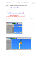
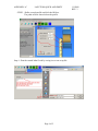
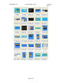
APPENDIX “A”
LAZYTURN QUICK AND DIRTY
1/9/2009
REV: 3
APPENDIX “A”
LAZYTURN QUICK AND DIRTY
This a quick and dirty step by step procedure to use LazyTurn.
These are the steps required:
1. Create the profile and save it as a version 12 DXF.
2. Run LaxyTurn, and when it opens, open / import the created DXF file.
The turning object is now shown.
3. Select a tool from the Lathe Tools menu. If none are shown on the left side
create one as follows:
A- Use the pull down to select the type,
B- define the tool by filling in the information,
C- provide a Tool Name,
D- click the Create as new tool box.,
E- click ok and the display closes
4. Reopen the Lathe Tool menu and select the tool.
5. Define a rough profile and click the OK box.
The paths are now shown below the profile.
6. Post the created lathe Gcode by saving it as a text file.
7. Open Mach3Turn and open the saved LazyTurn text file.
It is highly recommended that you read the manual as detailed information is provided
about all the steps.
Page 1 of 5
APPENDIX “A”
LAZYTURN QUICK AND DIRTY
1/9/2009
REV: 3
STEP 1 - Create the profile and save it as a version 12 DXF.
Step 2 - Run LaxyTurn, and when it opens, open / import the created DXF file.
Page 2 of 5
APPENDIX “A”
LAZYTURN QUICK AND DIRTY
1/9/2009
REV: 3
STEP 3 - Select a tool from the Lathe Tools menu. If none are shown on the left side
create one as follows:
A- Use the pull down to select the type,
B- define the tool by filling in the information,
C- provide a Tool Name,
D- click the Create as new tool box.,
E- click ok and the display closes
STEP 4 – Re-open the Lathe Tool menu and select the tool.
Page 3 of 5
APPENDIX “A”
LAZYTURN QUICK AND DIRTY
STEP 5 - Define a rough profile and click the OK box.
The paths are now shown below the profile.
Step 6 - Post the created lathe Gcode by saving it as a text or tap file.
Page 4 of 5
1/9/2009
REV: 3
APPENDIX “A”
LAZYTURN QUICK AND DIRTY
STEP 7 - Open Mach3Turn and open the saved LazyTurn text file.
Page 5 of 5
1/9/2009
REV: 3
APPENDIX “B”
CAD DRAWINGS AND COMMON MISTAKES
1/4/2009
REV: 3
1.0 PREFACE
1.0.1 The intent of this appendix is to provide generic drawing guidance in a way that:
- the basic profile of the object to be turned is understood
- basic program rules are understood
- the drawing imported into LazyTurn will not contain common CAD errors
So you will create a drawing of the profile which is importable into LazyTurn
and the learning curve is shortened .
1.0.2
This appendix is very focused on the intent and recommend the other appendixes
be reviewed for PC requirements, DXF file creation, practical profiles that can be
machined, etc..
1.0.3
This appendix will not teach you how to use any particular CAD / CAM program.
There are probably 100 CAD programs out there with varying complexity in how
they accomplish creating entities ( line, arc ), how they joint them, manipulate
them, and finally save them. Add to the above CAM / 3D programs and it’s
overwhelming.
1.0.4
2.0 LAZYTURN PROFILE
2.1 The profile in the drawing must be a connected series of entities.
2.2 One series only.
2.3 Think of it as a drawing showing ONLY the profile.
2.4 The 2D drawing can represent a radius or diameter (Y).
2.5 The drawing is done such that “Y” is vertical and “X” is horizontal.
2.6 It can be in metric or imperial units or even just units, ( later on the just
units )
2.7 LazyTurn converts Y / X to X / Z in the program.
3.0 RULES
3.1 The drawn profile must allow for tracing the profile in a single continuous
move over it’s complete length.
So if you were to trace over your profile with a pencil and need to lift your
pencil point off the line, to go to some part of the profile or touch something
like a line off the profile, then it is not a complete continuous line. Then you
may have problems trying to use the file in LazyTurn.
Page 1 of 5
APPENDIX “B”
CAD DRAWINGS AND COMMON MISTAKES
1/4/2009
REV: 3
3.1.1 Analogy:
Your driving a paved white line divided road and want to cross the river
ahead, but the paved road ends and there is no bridge, you can see another
bridge but can’t back up, so you take the no white lined unpaved road just
off the side and ahead of you, your car goes along but gets stuck in a pot
hole. Drive the correct road the first time and don’t get stuck. End of
story!
3.2 LayTurn needs to be told what your profile represents on import.
3.3 There are basic differences between a turning, facing, boring profile
(blue text = currently not implemented ) so for now all writing applies
to turning.
3.4 LazyTurn has built in features to reject or fix reasonable CAD errors created
by you in creating the profile.
3.5 Draw your profile in the correct quadrant as shown in Figure 3.4.1 below.
Draw wherever you want, but move the profile when done.
FIGURE 3.5.1
Page 2 of 5
APPENDIX “B”
CAD DRAWINGS AND COMMON MISTAKES
1/4/2009
REV: 3
3.6 Do not draw more than the top part / upper half of the profile.
You will get an error message “No appropriate drawing profile was found”
if the full profile is drawn.
3.8 Do not draw / leave a center line or any line which would represent the
the profile center line of the object.
3.9 DO NOT ….DO NOT draw, extend any line, any part of the profile,
leave any line / dot / pixel / or what ever below the Y=0 which represents
the center line. See FIGURE 3.5.1
3.10 Do not draw / leave a center line or any line which would represent the
the profile center line of the object.
3.11 Do not leave a vertical line going up or down at the end of the profile.
Although accepted it is not required or recommended.
3.12 Do not create multiple drawing entities , one existing under the other,
as this will cause an error " self intersection in master file" and no rendered
graphics will be displayed.
3.13 Do not leave vertical or parallel lines not connected to the profile ( very
close or far away from the profile ). Although ignored they should not be in
the drawing.
3.14 Do not leave a “space” very small or large in or between any element
which should be joined and be one continuous part of the profile. Common
spaces will usually occur are as follows:
- line to line
- end of a line crossing the end an adjoining line
- line to an arc
- line tangent to an arc
- arc to arc
- arc end crossing a matching arc end
3.15 Do not leave a line / circle / dot or any element in the area below the
profile and the center line / Y=0.
3.16 LazyTurn will reject lines in the lower half of the profile including lines
drawn through the profile and if they exist you will get an error message
telling you so.
3.17
Do not start the profile from a point and progress with the profile in a X
positive direction or said differently a dip in the face . This would be
considered a facing operation which is not implemented yet.
Page 3 of 5
APPENDIX “B”
CAD DRAWINGS AND COMMON MISTAKES
1/4/2009
REV: 3
3.18 The termination of the profile at the LEFT (Z-) end of the drawing MUST
extend, in the -z direction, BEYOND any other entity in the drawing. If the
profile ends with a downward arc, the end of the line must NOT go beyond a
line tangent to that arc, and perpendicular to the center line of the part.
3.18 Do not draw from the end of the profile through the profile. This will cause
an error " self intersection in master file" and no rendered graphics will be
displayed.
3.19 Do not draw a profile with an element going or turning in a downward /
backwards direction towards the face of the profile. The profile can proceed
downwards but must be at least perpendicular to the centerline of the object.
3.20
4.0 TEST
4.1 Can you relate to what is shown in Figure 4.1.0 compared to what was stated
in section 3.0?
FIGURE 4.1.0 (to be corrected)
4.2 You can draw almost any profile and it will work. When a profile is bad,
inferior, or problematic, LazyTurn will give you an error. The profile will appear
only as a single black outline and not a shaded three dimensional image in the
graphics screen. Should this happen you need to revise your drawing. There
should be no problems when the simple rules stated are followed.
5.0 GENERIC CAD TIPS
Page 4 of 5
APPENDIX “B”
CAD DRAWINGS AND COMMON MISTAKES
1/4/2009
REV: 3
5.1 Use any tool available in the program that will assist you in avoiding spaces
in the profile. Snap, chamfer, fillet, break, trim, extend are just a few by word
and may be called something different by individual programs.
5.2 Utilize the level or layer ability of the program. Name or create just one for
the profile only and keep dimensions or what ever on the others.
5.3 Always export only the profile turning off the other layers.
5.4 Zoom way in when connecting elements or snapping to a point or line. This
will eliminate most space and connection issues associated with the profile.
5.5 Use a properties box to compare start and end points of mating elements to
assure that they connected.
5.6 Connect tangentially to circles and provide smooth transitions by zooming in
and confirming the drafting.
5.7 When moving a profile to a start point use precision input to define the point
(like 0,0,0 ) it is going to.
5.8 CAD programs can be very complex and do amazing tasks, yet to generate
even a complex profile, only basic commands are utilized. So discipline
yourself to use that 5% of the program in an expert way.
5.9 Compose the profile from simple elements.
5.10
Don’t use points, constructions lines, invisible lines on the profile
layer.
Page 5 of 5
APPENDIX “C”
DXF FILE EXPORTS
1/5/2009
REV: 3
1.0 PREFACE
1.1 The intent of this appendix is to provide information about the transition of a
drawn profile into LazyTurn.
1.2 Lazyturn only requires an importable DXF file preferably Version 12.
Only DXF files are supported as of this writing.
2.0 DXF HISTORY
2.1 DXF stands for Drawing Exchange Format and was created by Autodesk
approximately 20 years ago. AutoCad is just one of it’s products. DXF is nothing
more than a common proprietary language providing a method of exchanging
( import and export ) drawing file information within AutoDesk products. DXF is
a generic language which AutoDesk controlled without having to give out their
own proprietary format.
2.2 The evolution of AutoDesk products have required revision of DXF. Since it was
propreitary and not shared with other CAD products in the market place the other
products interpreted the DXF to allow file exchange between competing products.
Intergraph and later Bently Microstation were two such products. Information
could be exported / imported by these products but at times the conversions left
something to be desired because of how the other products interpreted DXF.
2.3 The DXF had to address new complexities such as add-on packages, CAM, 3D
etc. thus additional information was required to define the drawing via DXF.
The DXF changed to address the complexity and here is a listing of versions.
AutoCad Release / DXF Version
12 / 12
13 / 13
14 / 14
2000 / 15
2004 / 16
2007 / 17
2008 / 17.1
2009 / 17.2
Page 1 of 4
APPENDIX “C”
DXF FILE EXPORTS
1/5/2009
REV: 3
2.4 AutoCAD 10 and up support both ASCII and binary forms of DXF. Prior
versions support only ASCII versions of DXF. You can read ASCII files by
opening the file with a text editor like Notepad since they contain text that
can be read. The binary form of DXF files are made up of more than just plain
text and have hex characters / bytes that are intended to be interpreted as
something other than text. The binary file could more easily represent complex
stuff like images, meshes, or whatever. It is more compact, takes less file space
and can be read and written more quickly by the computer.
2.5 The ASCII and binary DXF files contain a complete description of the AutoCAD
drawing. Now if an “1” is interpreted as a “I” when imported or exported to or
from another program problems can occur. The exchange has matured over the
years but it is still not perfect. Now suppose there are 100 CAD programs out
there and each interprets the exported and imported data ever so slightly or
differently. Suppose one program dosen’t even allow or recognize what it is
receiving? There certainly can be problems as all CAD programs are not created
equally.
2.6 There are accuracy issues as ASCII dxf files trade-off size and accuracy but
binary dxf files preserve all of the accuracy.
2.7 There are other formats but they will not be discussed.
2.8 LazyTurn addresses a lot of issues when importing a drawing of a profile.
The program has built in safeguards to avoid problems and confusion.
Appendix “B” addresses common issues which a user can eliminate in the
beginning and help make LazyTurn’s job of importing easier.
2.9 Manny CAD programs provide options on what drawing information should be
exported / contained in the DXF. It can be a challenge to define how the data
should be defined on export in a program. Frankly it should not be required.
2.10 Here are just a few options some offer:
- level to layer ( or whatever name it’s called ) changes inclusive off all the
associated parameters
- Entity conversion of all associated parameters
- Entities only such that the resulting DXF file contains only the profile section
based only the objects you select
2.11 Turning off / disabling / freezing the layers / level and keeping entities unrelated
to the profile like boarders etc. will provide a more acceptably defined DXF . It
just minimizes the interpretation talked about earlier.
Page 2 of 4
APPENDIX “C”
DXF FILE EXPORTS
1/5/2009
REV: 3
2.12 Data from conversion to conversion between programs can be carried over into
the next DXF thus complicating it.
2.13 Convert the file from a 3D to 2D drawing prior to DXF.
2.14 Clean, optimize, compress the drawing if provided by the program prior to DXF
export.
2.15 Exporting / importing between different programs may cause the profile location
relative to X=0 Y=0 so always check in your program prior to creating a DXF.
Some programs may actually reverse the profile 180 degrees.
2.16 The turning profile you provide via DXF for LazyTurn import
is very basic in it's elements and only requires fundamental descriptions.
2.17 Most applications provide for drawings to exported out as a Version 12 DXF.
Some versions were not as stable as others and new versions continue to this
day. Version 13 & 14 seems problematic Version 12 seems most acceptable
even though more recent versions will also work.
2.18 Here are some screen shots of AutoCad and MicroStation Options for saving a
file. If there is any doubt on the selection, select the one with “ASCII” in the
wording.Remember ASCII imports and Binary saves as a drawing to be opened
by CAD. You want to save as a AutoCAD ASCII DXF file (*.dxf) or
AutoCAD R/12 (*.dxf)
MICROSTATION SE & J
AUTOCAD 2000
MICROSTATION V8XM
AUTOCAD 2007
Page 3 of 4
APPENDIX “C”
DXF FILE EXPORTS
1/5/2009
REV: 3
3.0 PROGRAM DXF’S
3.1 The following programs provided successful DXF files for LazyTurn.
Turbo Cad
Vcarve
Turbocad V8.1, V9, Dekux 14
TurboCAD Deluxe 14.
BobCad,v18,v21,v22,
Rino v2.0,
CutViewerTurn
STDCAD
D2NC
MICROSTATION – all versions
AutoCad V12 and above
3.2 NOTED PROBLEMS & QUESTIONS
QCad.
Q1- I can not get this to load, it is just lines and arcs, no splines etc.It doesn't seem to
care
whether the DXF is x,y or x,z. based or where it's drawn in the Cad Quadrant layout
(adjust to 0,0 after loading)
R1- The column.dxf also has those annoying lights in it. When removed, it loads fine. Im
not sure how to sense those automatically, they are stored as lines and arcs, so the
program see's them as normal entities.. What I may do is just ignore the softest chains,
delete them, and keep the longest chain, that should solve many of these kinds of errors.
Page 4 of 4
APPENDIX “D”
POSTED DXF FILES
3/28/2009
REV: 2
The following is a listing of posted DFX files along with the associated reply# to the
LazyTurn thread. The higher the reply # the more recent the reply. A thumb nail image of
each file is also provided.
REPLY#
13
19
32
35
39
47
47
48
198
203
203
208
208
208
221
226
240
243
244
247
258
287
321
325
353
366
387
389
397
402
404
404
428
514
514
FILE NAME
A------new_test.dxf_E
A------new_test_G
King
A------mach3Cannon1_bigbiglimbo_I
A------King_Grahm_A_Rev_normal
Column
Pulley
Valve1
richTHREE_BALLS
test_v21_inlet_7
test_v21_inlet_8
DXF12_2000_1B_C4
DXF12_2000_2_C4
DXF12_2000_3_C4
DrawingA4TODO
5_DXF_HCIR
half_elisp_no_Leads
king_grahm_scaled_to_2_50_inch_AA
2d_12DXF_chip_243
8
swivel_socket_d
Cylinder
Flanged_Spindle_INCH
10DXF_HCIR
11_6DXF_HCIR
4_tman__lead_in_.2__00
2PROFILE_HANK
connrod_rodend_BIG_Hank_G
20_DXF_HCIR_EGGHEAD_Rich_A
20_DXF_MAN_REV1_VERTICAL
20_DXF_MAN_REV1
20_DXF_MAN_REV1A
Flanged_Spindle_INCH3
Arc.3_D_Good
Arc.3_E_Good
Page 1 of 4
COMMENTS
APPENDIX “D”
514
REPLY#
555
564
583
602
608
663
669
693
695
697
704
722
771
777
789
791
795
805
820
820
857
860
878
893
898
911
935
938
POSTED DXF FILES
Arc.3_F_Good
FILE NAME
Allison_Crush_Cyl
Balconspijl-willem
Roller_Test_Master_000_10_units
Copy_of_Roller_Test_Master_000_10_units
40_DXF_02SAME_HCIR
4pwn_dxf
4pwnRC_
CadStdLite
CadStdLiteArcs
BPIN
bpin_new
pulley1
1file_dxf
kandelaar40RC
woodenptxt
GOOD_Copy_of_king_grahm_scaled_to_2_...
01_16_09_Was_GOOD_9_DXF_HCIR_Rich
apin
Schachfigur_Dame
Schachfigur_Dame-4
Connecting_rod
Crosshead_guide_rev1
1x1.5x4_Long_Roller_Test_Master
Flywheel3_D
toolholders
Save_Inside_Inlet_New_Test_L
BPinapin
Test_AA
Page 2 of 4
3/28/2009
REV: 2
COMMENTS
APPENDIX “D”
POSTED DXF FILES
Page 3 of 4
3/28/2009
REV: 2
APPENDIX “D”
POSTED DXF FILES
Page 4 of 4
3/28/2009
REV: 2
APPENDIX “E”
PRACTICAL MACHINING CONSIDERATIONS
1/7/2009
REV: 2
1.0 PREFACE
1.1 This intent of this appendix is to assist in getting a profile turned on a lathe
using LazyTurn in combination with Mach3Turn software.
1.2 It is not intended to teach you how to operate your lathe or setup Mach3Turn.
1.3 The Mach3 Turn manual along with several other manuals for Mach cover
almost any topic relating to machine setup.
1.4 So this appendix will cover only those oddities or specifics which are not
covered by the other manuals.
1.5 Specific to LazyTurn is an understanding of how the cutting tool relates to
path generation based on the profile.
2.0 PATH GENERATION
2.1 The tool selected has a major impact on the cutting tool paths that LazyTurn
generates. The software uses the tool including it’s holder as a device to
constantly check against collision with parts of the profile to be turned.
Currently all tools are considered as cutting on the front and both sides.
2.2 The Left / Right / Center tool tip to holder relationship is currently not used in
to define the cutting edges. Selection of a certain relationship in the tool menu
only provides a visual display for the user as compared to his actual tool.
2.3 Possibly in the future, as the program develops, the tip to holder relationship
will become a selection to define which side of the tool tip will cut, such as ,
Left cuts with right side( towards the headstock), Right cuts with left side (
towards the tailstock) and Center ( a round nose tool ) cuts either side. To
keep gouging from occurring the cutting edge would be restricted to a point
on the nose radius. A line drawn back from the point on the nose tip to the
non-cutting side of the tip or holder into which the profile will not be allowed
to gouge would be defined as the backangle. See Figure 2.2.1
2.4 Rounding of sharp tangents or sharp corners may cause paths not to be
generated since the sharp corner can be considered the end of the profile.
A work around requires a small straight section be provided so collision
detection can take place. Another work around at this time would be to use the
stock diameter pointer to provide a larger stock size. The larger stock size
will allow for the program path algorithm to properly address the first pass.
Page 1 of 4
APPENDIX “E”
PRACTICAL MACHINING CONSIDERATIONS
1/7/2009
REV: 2
2.5 In the future a small amount may be added to the stock ( say 5%) on import.
Currently if you were to put the curser on the stock size pointer it represents
the actual profile diameter value. The user still has the option to increase or
decrease the diameter.
2.6
3.0 TOOL SELECTION
3.1 There are books written about lathe tooling. Inserts and holder dimensions
vary between manufactures even if the descriptions are similar. Specialty
shapes, nose angles, inscribed circular tolerances, relief angles, corner / tip
radius, and cutting edges are just a few parameters which define how the
insert along with the holder could clash with the profile. Take into
consideration hand or custom ground tools and the variance in how the tool
insert shape relates to clashing with an object is overwhelming.
3.2 Different lathe tools are primarily used for specific cutting actions.
LasyTurn currently doesn’t restrict what tool you choose to do a
particular operation. The same tool can be used for rough through finishing
operations and cut a complete profile.
3.3 Common sense regarding selection can be subjective depending on the user.
The program only knows what the user tells the software. Currently there are
no built in safeguards in tool selection and frankly provides for unrestricted
use of the software which in the end provides for flexibility.
3.4 It is up to the user to select or define a tool to do the operation. CNC only
implements the cutting more accurately and timely as compared to doing it
manually.
3.5
Corners / undercut/ offsets/
Units / before – during – after units/
Page 2 of 4
APPENDIX “E”
PRACTICAL MACHINING CONSIDERATIONS
1/7/2009
REV: 2
4.0 TOOL INPUT
4.1 It is now time for a change in the mind set in order to address all the tool
inputs. Namely, you need to think in terms of clashing or following the
profile with another object and apply common sense.
4.2 The tool you select or create must have a form which will allow the tool to
follow the profile. If the tool can’t follow the profile, then paths can’t be made
based on that tool.
4.3 Yes, in a sense, any tool can cut anything, even “skin” and it knows no better.
4.3 T The tool you select or create must have a form which will allow the tool to
follow the profile. If the tool can’t follow the profile, then paths can’t be made
based on that tool.
4.4 You wouldn’t expect a .2” tip radius to cut a square corner or a lesser radius.
4.5
Depends on the insert and the feeds. In the end that rear flank will be
taken into account, its just at the moment the development hasnt got there
yet. It requires a dual gouge sensing to sense not only a gouge to the profile
( currently working) but a gouge to the leftover material. ( Not
implemented.).
corners / undercut /
5.0 TOOL FEED RATE
5.1 LazyTurn turn currently provides feed rate and spindle rpm.
Future considerations may include other values like inches / rpm
or MM / rpm which most manual lathes have associated via change gears or
quick change gear boxes.
6.0 PASS CONSIDERATIONS
Page 3 of 4
APPENDIX “E”
PRACTICAL MACHINING CONSIDERATIONS
6.0 MACHINE TEST PROGRAMS
Accuracy test
Repeatability test
Gcode sub program
Page 4 of 4
1/7/2009
REV: 2
APPENDIX “F”
PC REQUIREMENTS
1/30/2010
REV: 2
PERSONAL COMPUTER REQUIRMENTS
PC TYPES AND SOME KNOW PROBLEMS
The X pointers have no color, the Z ones do ....in the normal view.Flip the display
and the opposite is true.
I have red brown and blue showing for the X and green and yellow showing for the
Z.When you flip the view, they're the same colors.
you see my rulers on both sides as well.
OpenGL errors are likely due to old openGL implementations, I tend to use new ones, so
update video drivers if you get openGL errors,
they may be caused by video card drivers not likeing some OpenGL lighting modes.
The error seems to be from your OpenGL system..
HERE ARE SOME COMPUTERS WHICH WERE TESTED FOR PIONTER
CHANGING COLOR
develop on a asus 2.3Ghz unit, with 1Terabyte of harddrive space and 2 24" monitors.
special..
All versions of the LAZYTURN application dated from NOV 9 thru and including DEC
17 will work with what is loaded on the laptop. TODO as soon as the application is
replaced with the DEC 23 or DEC 23-1.
The laptop is 500 mhz / 512 memory while the other computer is 3 ghz / 2 gig memory.
I'm getting the same 214 error code as Chip on the LAPTOP.RICH
MODIFIED: COMPUTER #3 - 2.4ghz / 512 ram
Works fine on this one, error on exit, but no loss of X
pointer color . I upgraded this computer to MACH v*********.20
and tried files from the other two computers.
SUMMARY: PC#1 - loss of x pointer color / otherwise good
PC#2 - can't use any version lazyturn application after DEC 17
PC#3 - no problems
PC#4 - CAN'T USE ANY VERSION LAXYCAM APPLICATION
AFTER DEC 17 " NO LOSS OF X POINTER COLOR"
Just a guess, but from DEC 17 version back, the mouse pointer didn't change to a cross
hair in the graphics part of display. The error happens when you click the "open" box in
the file open pop up screen.
Page 1 of 4
APPENDIX “F”
PC REQUIREMENTS
1/30/2010
REV: 2
Well added another pc#4 for testing, NEC LAPTOP 400MHZ / 256 RAM.Only good
to prior 12 23 08 versions and will give the ( 214 error for dec 24 ver ),
(TODO for dec 24-3 ver) , ( 406 error for dec 25 ver), but it dosn't loose the color in the
x trangles.
Changing accel values didn't do any good. All the computers here are set to the highest
accel.
Lets see, four different computers here of varying make and model all running XP. The
slower ones with less than 500 mhz / 512 only get to prior versions of DEC 23. The
fastest / most memory only has a problem wiith loss of color in the pointer / unless you
flip it 180 degrees ( along with oss of color in the associated dimension boxes) but can
run the DEC 25 VER with no problems other than stated.
Tried LT on three more computers: "" using DEC 25-4 version ""
FPC#1- 3 GHZ / 1G RAM - CUSTOM- XP PRO SP2 -----------NO PROBLEMS
FPC#2- 900 MHZ / 256 RAM - LAPTOP- XP PRO SP2 -------WON'T RUN ANY
VERSION AFTER DEC 17"" ie; it will not create a graphic profile ""
FPC#3- 3.6 GHZ / 1.5G RAM - EMACHINE -XP PRO SP2 ----X POINTER COLORS
ARE LOST
FPC#2- 900 MHZ / 256 RAM - LAPTOP- XP PRO SP2 -------WON'T RUN ANY
VERSION AFTER DEC 17
Thats a weird one.. video hardware accel maybe? Seems an openGL
implementation issue, cant repeat it here at all, and cant think of
how to check it any. I basically tell it a colour, and it shoudl be
correct.. all kinda Windows magic from there..
Using the DEC 29 version.The graphics look right along with the paths
My pc is a dualcore 1.9ghz 1gb memory laptop so that should be sufficient.
Could some of the differences we are experiencing be attributed to running XP with
Service Pack 2 as opposed to 3 ?Just curious. I do not recall seeing any mention of it
earlier.Mine is XP SP3.
Page 2 of 4
APPENDIX “F”
PC REQUIREMENTS
1/30/2010
REV: 2
I did some experimenting trying to correct the pointer color display. I found this:
With the acceleration at FULL, there is no 406 error. However, if it is
lowered to the setting shown, I get the 406.I always keep mine FULL so I wasn't getting
the errors.
Did try the settings from RC and get the same results, no error on full acceleration and a
406 error on lower setting. Doesn't seem to help hear, My BobCad v23 won't tolerate a
setting above 2 clicks from None on the Acceleration.
Try this DXF on HIGH.. see what you get. ACad, Autodesk, Autosketch Generated
I found that if I leave autocad open even after saving the
files and exiting the file, lazy turn comes back open gl. If I shut down
autocad completley lazyturn opens the file perfectly. Obviously autocad
2009 still holds the file slightly open in its memory.
Most of the time you can open the same file in several programs and only
run into trouble with trying to save a file with changes made to it, If
others are open
MACH TURN REMARK
The ragged view you last bottom post is just a "view" display issue in
Mach3, You probably have the F speed set very high or in over-ride.
I see this quite often, It mostly shows up mid way in a lot of single axis
g-code moves and isn't in the actual step or dir Output's.
Slow the F speeds down with Over-Ride and let me now.
As Chip says, the ragged green line is only indicative of too fast a
feedrate on a small object, Mach3 then cant keep up the display smoothly.
Page 3 of 4
APPENDIX “F”
PC REQUIREMENTS
1/30/2010
REV: 2
Thats not an issue with LTurn really
Also, could you please explain what this LEAK represents ?
It is present after closing LT but only when a path has been generated.
The Leak isnt actual, its a warning that the object wasnt deleted by LTurn as it closed,
I need to search for it, very small
objects so its not a big deal really. Seems intermittant
Page 4 of 4