1
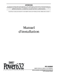
•W AR NI N G •
Please refer to the System Installation Manual for information on limitations regarding product use and
function and information on the limitations as to liability of the manufacturer.
Long Range Radio
Alarm Transmitter
UT
Installation
Manual
Version 1.31
Table of Contents
FEATURES
Keypad Programmable .................................................
EEPROM Memory .........................................................
Static/Lightning Protection ............................................
Supervision ...................................................................
Operation ......................................................................
1
1
1
1
1
1
SPECIFICATIONS ......................................................... 1
INSTALLATION ............................................................. 2
Locating the LINKS2150 .............................................. 2
Mounting the LINKS2150 ............................................. 2
Mounting the cabinet .................................................... 2
LINKS2150 diagram ..................................................... 2
Power Terminals + 12v – .............................................. 2
TRBL Trouble Terminal ................................................ 3
AC TRBL Input Terminal ............................................... 3
LB TRBL Input Terminal ............................................... 3
OUT TRBL Output Terminal .......................................... 3
YEL and PGM PANEL Terminals ................................. 3
COM Terminal ............................................................... 3
YEL and GRN KEYPAD Terminal ................................ 3
VZ and Z1 to Z8 Terminals ........................................... 3
MOD OUT and V SUP Terminals .................................. 3
OPERATION .................................................................
Normal Operation .........................................................
Trouble Display .............................................................
Zone Light .....................................................................
OUT TRBL Terminal .....................................................
4
4
4
4
4
PROGRAMMING THE LINKS2150 ...............................
Programming Data .......................................................
Section [10] System Configuration ...............................
Binary Data Display ......................................................
Reviewing Programmed Data ......................................
HEX Data Programming ...............................................
5
5
5
5
5
5
LINKS2150 PROGRAMMING SECTIONS ...................
[01] 2150 Radio Account Code ..................................
[02] Alarm Reporting Codes, Zones 1 to 8 .................
[03] Restoral Reporting Codes, Zones 1 to 8 .............
[04] PC 16-OUT Event Activation
Reporting Codes 1 to 8 .................................................
6
6
6
6
6
This manual is for the LINKS2150 software version 1.31.
[05] PC 16-OUT Event Activation
Reporting Codes 9 to 16 ............................................... 7
[06] PC 16-OUT Event Restoral Reporting
Codes 1 to 8 .................................................................. 7
[07] PC 16-OUT Event Restoral Reporting
Codes 9 to 16 ................................................................ 8
[08] Maintenance Alarm Reporting Codes ................. 8
[09] Maintenance Restoral Reporting Codes ............. 8
[10] System Configuration .......................................... 9
[11] Installer’s Code .................................................. 11
[12] System Times ..................................................... 11
[13] System Clock ..................................................... 11
[14] System Date ....................................................... 11
[90] Installer Lockout Enable .................................... 11
[91] Installer Lockout Disable ................................... 11
[99] Restore Factory Default Programming .............. 11
HOOK-UP DIAGRAM
12
PROGRAMMING WORKSHEETS
13
[01] 2150 Radio Account Code ................................ 13
[02] Alarm Reporting Codes, Zones 1 to 8 ............... 13
[03] Restoral Reporting Codes, Zones 1 to 8 ........... 13
[04] PC 16-OUT Event Activation Reporting
Codes 1 to 8 ................................................................ 13
[05] PC 16-OUT Event Activation Reporting
Codes 9 to 16 .............................................................. 13
[06] PC 16-OUT Event Activation Reporting
Codes 1 to 8 ................................................................ 14
[07] PC 16-OUT Event Restoral Reporting
Codes 9 to16 ............................................................... 14
[08] Maintenance Alarm Reporting Codes ............... 14
[09] Maitenance Restoral Reporting Codes ............. 14
[10] System Configuration ........................................ 15
[11] Installer’s Code .................................................. 15
[12] System Times ..................................................... 15
[13] System Clock ..................................................... 15
[14] System Date ....................................................... 15
[90] Installer’s Lockout Enable ................................. 15
[91] Installer’s Lockout Disable ................................ 15
[99] Restore Factory Default Programming .............. 15
LIMITED WARRANTY
Features
•
•
•
•
Transmits alarm information to a long range radio network
Features 8 alarm zones
Varitech Transmission Format option
Interfaces with DSC Control Panels and transmits
reporting codes for PC16-OUT events
• Supports DSC Control Panels’ Serial Output Option
Keypad Programmable
The LINKS2150 is complete with a default program and is
operational with minimum programming. The LINKS2150
is completely keypad programmable.
EEPROM Memory
The LINKS2150 uses EEPROM memory which will retain
all program information even if AC and battery power is
removed. The EEPROM memory can be reprogrammed
thousands of times.
Static/Lightning Protection
SPECIFICATIONS
• 8 positive or negative triggered zone inputs
-positive voltage trigger: 4 to 14 VDC
-negative voltage trigger: 0 to 0.8 VDC
-input impedance: 10kΩ
-maximum zone loop resistance: 100Ω
• 2 negaitve triggered trouble inputs
-negative voltage trigger: 0 to 0.8 VDC
• Required power supply: 11.5 to 14VDC at 1A
• Trouble Output: 50mA
• Programmable with the DSC PC2550RK Keypad
• Radio transmitter frequency: as specified on transmitter
unit
• Antenna (not supplied):
-Larsen MHW-450, 50Ω vertical antenna
-450 - 470 MHz
• Cabinet dimensions:
-11’ high x 11.8’ wide x 3.3’
(279 mm x 300 mm x 84 mm)
• Cabinet colour: light beige
The LINKS2150 has been carefully designed and tested to
provide reliable protection against static and lightning
induced transients. Our special “Zap-Trac” circuit board
design catches high voltage transients right at the wiring
terminals, and transient protection devices are placed in all
critical areas to further reduce damaging voltages.
Supervision
• Low or disconnected external battery
• Loss of external AC power
• Security control panel connection supervision
Operation
• Long-Range radio alarm transmitter
• Compatible with PC-16OUT functions on the PC1500,
PC1550, PC2525, PC2550, PC3000
• Compatible with serial output functions on the PC2525
v1.1 or later, PC2550 v1.31 or later, PC3000 v7.71 or
later and the PC4020CF V2.1 or later. Ensure that the
control panel is equipped with the proper software
version;refer to Section [10] on page 10 for
information
• 8 zone inputs for stand-alone operation
• Capable of reporting PC-16-OUT Output Module events
• 4 LINKS2150 Trouble Reporting Codes and Test
Transmission Reporting Code
• Programmable Test Transmission Time
• Programmable zone response time
• Inputs for external power supply trouble indications
• System Clock and Date
• Installer Lockout feature
• Programmed with the DSC PC2550RK LED keypad
WARNING:
DO NOT connect both a
PC5400DVACS and a LINKS2150
module to the same system.
You can connect both a PC5400
printer module and a LINKS2150 to
the same system.
1
INSTALLATION
Locating the LINKS2150
Locate the LINKS cabinet in a convenient location next to
the already installed security system control panel cabinet.
As much as is reasonably possible, the LINKS2150 should
not be located near sources of interference. These include
sources of electrical noise such as computers, televisions
and electric motors in appliances and heating and air
conditioning units, as well as large metal objects like
heating ducts and plumbing which may shield the antenna.
If the cabinet must be located near such items, the LINKS
antenna may have to be mounted on a remote bracket
away from the cabinet. Whenever possible, locate the
LINKS2150 as close as possible to the security system
alarm control panel.
Mounting the LINKS2150
Mount the LINKS cabinet in a convenient location next to the
already installed security system control panel cabinet. As
much as is reasonably possible, do not mount the LINKS2150
near sources of interference. These include sources of
electrical noise such as computers, televisions and electric
motors in appliances and heating and air conditioning units,
as well as large metal objects like heating ducts and plumbing
which may shield the antenna. If the cabinet must be located
near such items, the LINKS antenna may have to be mounted
on a remote bracket away from the cabinet. Whenever possible,
mount the LINKS2150 as close as possible to the security
system alarm control panel.
Mounting the Cabinet
If it is not already installed, install and test the security system
according to the instructions found in the security system’s
Installation Manual.
Remove the LINKS2150 and mounting hardware from the
cardboard packaging. Before attaching the cabinet to the wall,
press the supplied mounting studs into the raised mounting
holes from the back of the cabinet.
Mount the cabinet securely to the wall. It is recommended that
appropriate wall anchors be used when securing the panel to
drywall, plaster, concrete, brick or other similar surfaces.
Install the LINKS2150 in the mounted cabinet. Locate the
antenna connection in the hole at the top of the cabinet and
press the LINKS2150 onto the nylon mounting studs. Insert
all cables into the cabinet and prepare them for connection.
Secure the antenna to the LINKS2150 antenna connector.
Tighten the antenna “finger tight” only.
NOTE: An antenna should always be connected to the
LINKS2150 whenever it is operated. The unit will not
function properly and may be damaged if an antenna is not
installed.
Do not connect the power supply until all other wiring,
including the antenna connection, has been completed and
checked to ensure that it is correct. Incorrect wiring
connections may cause the LINKS unit to operate
improperly, or may damage the LINKS unit.
2
LINKS2150 shown mounted in cabinet
Power Terminals + 12v –
Connect the power terminals (+ 12V –) to the BELL+ and COM
terminals of the control panel as shown inthe diagram on page
18. If a local bell/siren is to be used, it must have a separate
power source. The LINKS2150 must be powered frp, tje BELL/
COM terminals and as well must be the only device powered
by the BELL output.
Do not apply power to the unit until all wiring connections are
completed and the antenna is attached to the unit.
The connections between the LINKS2150 and the control
panel should not be greater than the lengths specified in the
table shown below.
Wire Gauge
Maximum Wire Length
AWG
feet / metres
22
15' / 4.5m
20
25' / 7.5m
18
40' / 12.0m
The maximum wire length may be doubled if the conductors
are doubled and connected in parallel. Whenever possible,
locate the control panel as close to the LINKS2150 as
possible.
TRBL Trouble Terminals
AC TRBL Input Terminal
The AC TRBL input terminal is used to report AC failure
troubles. If the power supply being used has an AC failure
trouble output, connect the output to the AC TRBL terminal.
When the AC TRBL terminal is shorted to ground, the
LINKS2150 will transmit the External AC Trouble reporting
code programmed in section [08].
LB TRBL Input Terminal
The LB TRBL input terminal is to report low back-up battery
trouble. If the power supply being used has a low battery
trouble output, connect the output to the LB TRBL terminal.
When the LB TRBL terminal is shorted to ground, the
LINKS2150 will transmit the External Low Battery Trouble
reporting code programmed in section [18].
OUT TRBL Output Terminal
The OUT TRBL output terminal will switch to ground when the
LINKS2150 detects a trouble condition. The OUT TRBL
terminal may be connected to a control panel zone terminal
to report LINKS2150 trouble conditions to the security system,
or the OUT TRBL terminal may be used to activate a visual or
audible trouble indicator.
YEL and PGM PANEL Terminals
If the LINKS2150 is being used for stand-alone operation, do
not connect these terminals.
If the LINKS2150 is being used with the PC 16-OUT option
enabled (see programming Section [10]), connect the YEL
and PGM terminals to the KEYPAD YEL and PGM terminals
of the DSC control panel being used with the LINKS2150.
Refer to the Hook-up Diagram in the back of this manual for
instructions on making the control panel connections.
If the LINKS2150 is being used with the Serial Input option
enabled (see programming Section [10]), connect the PGM
terminal to the PGM terminal of the DSC control panel being
used with the LINKS2150. When using the Serial Input option,
do not connect the YEL terminal. Refer to the Hook-up Diagram
in the back of this manual for instructions on making the control
panel connections.
YEL and GRN KEYPAD Terminal
The LINKS2150 is programmed with a DSC PX2550RK
Keypad; the keypad is not intended to be perminanently
connected to the LINKS2150. A PC2550RK keypad with a
short length of 4-conductor cable and alligator clips or test
leads will be convenient for programming and testing
LINKS2150 units.
Connect the YELLOW and GREEN leads from the PC2550RK
keypad to the YEL and GRN KEYPAD terminals. Connect the
RED keypad lead to the VZ terminal, and the BLK keypad lead
to the COM terminsl. Note that the PC2550RK keypad
connected to the LINKS2150 will only perform functions on
the LINKS2150; the security system connected to the
LINKS2150 cannot be operated from the keypad connected
to the LINKS2150.
NOTE: An alarm may be generated when connecting or
disconnecting the keypad from the COM and VZ terminals.
VZ and Z1 to Z8 Terminals
The VZ terminals are 12VDC outputs used for the
LINKS2150 zone connections. Z1 through Z8 are the
terminals for Zones 1 through 8. Refer to the Hook-up
Diagram in the back of this manual for instructions for
making zone connections.
MOD OUT and V SUP Terminals
These terminals connect the LINKS2150 to the radio transmitter.
These connections are made at the factory and should not
be altered.
COM Terminal
When using the LINKS2150 with a security system, connect
the COM terminal to the negative DC power supply terminal
of the security system control panel.
The COM terminal is also used for making zone connections.
Refer to the Hook-up Diagram for instructions on making zone
connections to the LINKS2150.
3
OPERATION
The PC2550RK keypad provides complete system status
operation, including LINKS2150 zone status and trouble
condition information. The keypad is also used to program
the LINKS2150 reporting codes and system options.
The keypad’s 8 zone lights provide alarm and status
indication for the alarm circuits. When the [ ] key is
pressed, the zone lights are used to display trouble
conditions.
∗
Note that the keypad connected to the LINKS2150 is
only used to operate and display information from the
LINKS2150 unit. The keypad connected to the LINKS2150
cannot operate or display system information from an
alarm control panel connected to the LINKS2150. If the
LINKS2150 is connected to a security system, the keypad
should be removed once the LINKS2150 has been
programmed.
Normal Operation
During normal operation, the PC2550RK keypad will be in
the Ready mode with the “Ready” light illuminated.
Activity on the LINKS2150 zone terminals (terminals Z1
throughZ8) will be indicated on the Zone Lights; when a
zone is activated, the Zone Light will come ON.
If a LINKS2150 trouble condition is detected, the
‘Trouble”light will come ON. Press [ ] to view trouble
conditions.
∗
Note that the zones on the LINKS2150 are “armed” at all
times.
Trouble Display
The LINKS2150 continuously monitors for four trouble
conditions. If one of these conditions occurs, the keypad
“Trouble light will come ON and the keypad will sound two
short beeps every 10 seconds. To silence the buzzer,
press the [#] key; the sounder will be silenced but the
“Trouble” light will remain ON until the trouble condition is
cleared. Trouble conditions may be reported to the
monitoring station by programming alarm and restoral
reporting codes in Sections [08] and [09].
∗
To view the trouble condition, press[ ]. Trouble conditions
will be indicated on the keypad Zone Lights:
Zone Light
[1] Internal Low Voltage Trouble:
If the DC supply to the LINKS2150 drops below 10.9VDC
for more than 4 minutes, this trouble will be indicated. This
trouble condition will only be cleared after the DC supply
voltage returns to 11.6 VDC or higher for more than 4
minutes.
NOTE: The LINKS2150 will not power up with a low
voltage from the power supply. Ensure that a 12Vdc
supply is connected to the LINKS2150.
[2] External AC Trouble:
If the AC TRBL terminal is switched to ground, the
LINKS2150 will generate an External AC Trouble. This
trouble is used to report AC trouble conditions generated
by an “intelligent” power supply.
4
[3] External Low Battery Trouble:
If the LB TRBL terminal is switched to ground, the LINKS2150
will generate an External Low Battery Trouble. This trouble is
used to report low battery trouble conditions generated by an
“intelligent” power supply.
[4] Control Panel Connection Trouble:
If the connection between the LINKS2150 and the security
control panel is interrupted for more than 90 seconds, this
trouble will be generated. This trouble will only be displayed
if either the PC16-OUT or Serial Input options in Section [10]
are enabled. This trouble condition will be automatically
cleared when wiring or programming errors are corrected.
[5] Loss of Time Trouble:
This trouble condition will be displayed whent he LINKS2150
is powered up after having lost power. This condition will only
be displayed if a Test Transmission time is programmed in
section [12]. This trouble will be cleared after trouble conditions
are displayed and the display mode is exited, or after the
system clock is reset in Section [13].
To exit the trouble display mode, press the [#] key.
If [9] is pressed while in the trouble display mode, the most
recent trouble will be displayed on the zone lights. This trouble
memory is useful as a diagnostic tool when installing and
servicing the LINKS2150.
OUT TRBL Terminal
When a trouble condition is generated, the OUT TRBL terminal
will switch to ground and will remain switched until the trouble
condition is cleared. This output may be used to activate a
trouble indicator, such as an LED indicator, a low current
sounder, or an RM-1 relay connected to another device. The
OUT TRBL terminal may also be connected to a zone terminal
on a security control panel to report LINKS trouble conditions
to the security system.
PROGRAMMING THE LINKS2150
Enter the Installer’s code. The default Installer’s Code is
[2150]; the code may be changed in Programming Section
[11].
When the Installer’s Code is entered, the “Armed” light will
come ON andthe “Program” light will FLASH. The
LINKS2150 is now ready to be programmed. To exit the
programming mode and return to the “Ready” mode, press
the [#] key.
NOTE: If no key is pressed for more than two minutes,
the LINKS2150 will return to the Ready mode and the
Installer’s code will have to be entered again.
With the “Armed” light ON steady, enter two digits for the
section to be programmed. Programming sections range
form[01] to [14], and special sections [90], [91] and [99].
Each section may be programmed individually.
Once the desired section has been entered, the “Armed”
light will be shut OFF, the “Ready” light will be ON, and the
“Program” light will FLASH. The keypad will also beep 3
times. Programming data may now be entered.
Programming Data
by pressing [0]. When the option selections have been
made, press [#] to save the selections in memory and
return to the program mode.
Binary Data Display
Zone Lights 1 through 4 are used to display the binary
value of the data as shown in the table below.
HEX data entry
Refer to HEX Data Programming
Value
Zone
Zone
Zone
Zone
0 1 2 3 4 5 6 7 8 9 A B C D E F
1
2
3
4
Zone Light ON
Zone Light OFF
Reviewing Programmed Data
• Enter the section to be programmed by entering the 2digit section number.
Most sections contain groups of 2-digit entries. The keypad
will beep twice after each 2-digit group is entered.
• Zone Lights 1 through 4 will represent the value, in
binary format, of the first digit in the section.
When a section is entered, Zone Lights 1 through 4 will
indicate, in binary format, the value of the first digit in the
section; refer to the Binary Data Display Chart.
• Press the [F] key to advance the display to the next
digit.
If you wish to change that digit, simply enter the new digit. If
you wish to keep that digit unchanged, you can enter the
same number or skip over the digit by pressing the [F] key.
Hexadecimal numbers may also be entered in most
sections. Refer to the Hexidecimal Data Programming for
instruction on programming hex data.
When the first digit has been entered or skipped, the Zone
Lights will display the value of the next digit. After each
digit is entered or skipped, the Zone Lights show the value
of the next digit.
When all data for a section is entered or reviewed, the
keypad will beep several times and the “Armed” light will
come ON and the “Ready” light will be shut OFF.
At this point, you will be in the program mode. Enter the 2digit number of the next section to be programmed.
It is not necessary to program all 2-digit pairs in a section.
A section can be entered and selectively programmed by
going only to the digit or digits you wish to change,and
then pressing [#] to return to the programming mode.
• At the end of the section, the keypad will beep several
times and then return to the Program Mode so that
another section can be selected for review or
programming.
HEX Data Programming
Certain programming sections may require the entry of
data in HEX (hexadecimal, or base 16) format. HEX
numbering uses the numbers 0 through 9 and the letters A
through F.
The letters A through F are represented by the number
keys 1 through 6. To enter data in HEX format, first press
the [ ] key; the “Ready” light will FLASH. Press a number
key from [1] to [6] to enter a HEX digit. The “Ready’ light will
stop flashing, indicating that the next keypress will enter a
decimal value.
∗
To enter HEX numbers:
∗ ∗
B ....... Enter [∗][2][∗]
C ....... Enter [∗][3][∗]
D ....... Enter [∗][4][∗]
E ....... Enter [∗][5][∗]
F ....... Enter [∗][6][∗]
A ....... Enter [ ][1][ ]
For 2-digit numbers, both digits must be programmed
before pressing the [#] key. Only the data entered before
pressing the [#] key will be changed.
Section [10] System Configuration
Section [10] allows system options to be enabled or
disabled. Section [10] uses the Zone Lights to indicate
which options are selected; press the corresponding
number keys to turn the options ON and OFF. When
section [10] is entered, Zone Lights 1 to 8 will display
which option are selected. Pressing the number key
corresponding to the option’s Zone Light will alternately
turn light ON and OFF. All lights can be turned OFF at once
When the “Ready” light is ON STEADY: data is entered
in decimal
When the “Ready” light is FLASHING: data is entered in HEX
∗
If the [ ] key is pressed accidentally while entering data,
press the [ ] key a second time to exit the HEX data entry
mode.
∗
5
LINKS2150 PROGRAMMING SECTIONS
[01] 2150 Radio Account Code
This 4-digit code is used to identify the system and is
transmitted when the LINKS2150 initiates
communications. Program a 4 digit code in this section.
Enter the code using numbers from 0 to 9 only.
Note: An account code must be entered before
communications through the LINKS2150 can be
used. Do not enter Hexadecimal numbers in this
section.
[02] Alarm Reporting Codes, Zones 1 to 8
Enter eight 2-digit codes for the Alarm Reporting Codes
for the LINKS2150 zones. These codes are used to report
alarms on zones 1 through 8.
NOTES:
• On the PC1500, PC1550, and PC2525, the Reporting
Code for event 8 is transmitted along with the Reporting
Code for the zone programmed as the Fire Zone.
• One the PC2550, if the AUX Input is programmed for
Momentary Key Arming or Forced Answer in Section [30],
Event 7 AUX Input will not be reported.
• On the PC3000, if the AUX Input is programmed for
Momentary Key Arming or Forced Answer in Section [28],
Event 7 AUX will not be reported.
[03] Restoral Reporting Codes, Zones 1 to 8
Enter eight 2-digit codes for the Restoral Reporting
Codes for the LINKS2150 zones. These codes are used
to report restorals in zones 1 through 8.
[04] PC 16-OUT Event Activation Reporting
Codes 1 to 8
The LINKS2150 is designed to transmit reporting codes when
PC 16-OUT events occur on a connected DSC control panel.
Programming sections [04] through [07] contain the reporting
codes that will be transmitted to report PC 16-OUT events and
restorals. To use this feature, be sure to enable the PC 16-OUT
function in Programming Section [10]. If the PC 16-OUT
reporting feature is not to be used, do not program reporting
codes in these sections and do not enable the feature in
section [10].
NOTE: A PC 16-OUT Module is not required to report PC 16OUT events. Refer to the Hook-up Diagram in the back of
this manual for instruction on connection a control panel to
the LINKS2150.
To use the PC 16-OUT reporting feature, ensure that the PC
16-OUT option is enabled in the DSC control panel connected
to the LINKS2150.
Control Panel
Enable PC16-OUT Operation in...
PC1500 / PC1550
PC2525
PC2550
PC3000
Section
Section
Sectoin
Section
[13]
[08]
[16]
[19]
Light
Light
Light
Light
4
6
4
4
If the LINKS2150 Programming section [04], enter eight 2digit codes for PC16-OUT events 1 through 8. These codes
will be transmitted when PC16-OUT events 1 through 8
occur. the chart below describes PC16-OUT events 1
through 8.
Event
6
PC2525
PC2550
PC3000
1
PC1500 / PC1550
Zone 1
Zone 1
Zone 1
Zone 1
2
Zone 2
Zone 2
Zone 2
Zone 2
3
Zone 3
Zone 3
Zone 3
Zone 3
4
Zone 4
Zone 4
Zone 4
Zone 4
5
Zone 5
Zone 5-8
Zone 5-8
Zone 5-8
6
Zone 6
Not Used
Not Used
Zones 9-16
7
Not Used
Not Used
AUX Input
Aux Input
8
Fire
Fire
Fire
Fire
• For all systems, Event 8 will not be transmitted until
the security system’s 30-second warning delay has
expired.
NOTE: PC4020 does not support PC16-OUT operation
[05] PC16-OUT Event Activation
Reporting Codes 9 to 16
[06] PC16-OUT Event Restoral Reporting
Codes 1 to 8
Enter eight 2-digit codes for the activation of PC16-OUT
events 9 through 16. These codes will be transmitted
when PC16-OUT events 9 through 16 occur. The chart
below describes PC16-OUT events 9 through 16.
Event PC1500 / PC1550
PC2525
PC2550
PC3000
9
Trouble
Trouble
Trouble
Trouble
10
Bypass
Bypass
Bypass
Bypass
11
Armed
Armed
Armed A
Armed A
12
Armed
Armed
Armed B
Armed B
13
[P]anic Key
[P]anic Key
[P]anic Key
[P]anic Key
14
[A]uxiliary Key
[A]uxiliary Key
[A]uxiliary Key
[A]uxiliary Key
15
[F]ire Key
[F]ire Key
[F]ire Key
[F]ire Key
16
PGM Output
PGM Output
PGM Output
PGM Output
NOTES:
• The event 9 Reporting Code (Trouble) is a general system
trouble report which will be transmitted whenever there is
a trouble condition on the control panel connected to the
LINKS2150. The Event 9 Reporting Code cannot specify
which trouble condition is present on the control
panel.
• The Event 10 Reporting Code (Bypass) is transmitted at
the end of the security’s Exit Delay if the security system
is armed with manually bypassed zones. Five seconds
after the end of the Exit Delay, the Event 10 Restoral Code
will be transmitted. Note that Event 10 reports manually
bypassed zones only; it does not indicated HomeAway bypass status.
• If the security system does not use Split-Arming, reporting
codes do not need to be programmed for both Events 11
and 12.
• When using the PC1500 or PC1550, note that the factory
default settings for these control panels cause the PGM
output to be normally active. This will cause the Event 16
PGM Output reporting code to be transmitted if one is
programmed.
Enter eight 2-digit codes for the restoral of PC16-OUT events
1 through 8. These codes will be transmitted when PC16-OUT
events 1 through 8, as described in Section [04], are restored.
NOTES:
•
Transmission of the Restoral Codes for Events 1 through
6 is dependant upon the Zone Restoral Option programmed in
the DSC security system connected to the LINKS2150.
Restorals may be programmed to be transmitted on Bell Timeout,
or they may be programmed to be transmitted when the zone
is restored to a non-alarm state. When the security system is
disarmed, restoral codes for 24-hour Zones will be transmitted
when the detection device connected to the zone is restored to
a non-alarm state. When the security system is armed, the
restoral codes for 24-hour Zones will be transmitted
according to the setting of the zone restoral option. The chart
below indicates where the zone restoral option is programmed
in each of the DSC control panels compatable with LINKS2150:
Control Panel
Program Zone Restoral Option in...
PC1500 and PC1550
PC2525
PC2550
PC3000
Section
Section
Section
Section
[31]
[46]
[15]
[18]
Light
Light
Light
Light
6
2
2
2
• The Restoral Codes for Events 7 and 8 are transmitted as
soon as the zone is restored.
• For the PC2550, if the AUX input is programmed for
Momentary Key Arming or Forced Answer in Section [30],
Event 7 AUX input will not be reported.
• For the PC3000, if the AUX input if programmed for
Momentary Key Arming or Forced Answer in Section [28],
Event 7 AUX input will not be reported.
• The Event 16 Reporting Code (PGM Output) is used to
indicate the deactivation of the PGM Output on the security
system connected to the PC16-OUT. Refer to section [05] for
information on where to program the security system’s PGM
Output options. Also, refer to the security system’s
installation Manual when programming output options.
NOTE: PC4020 does not support PC16-OUT operation mode.
• The Event 16 Reporting Code (PGM Output) is used to
indicate the activation of the PGM Output on the security
system connected to the PC16-OUT. PGM Output options
for each DSC system are programmed in the following
programming sections:
Control Panel
PC 1500 and PC1550
PC2525
PC2550
PC3000
Program PGM Option in...
Section [24]
Section [06]
Section [30]
Section [28]
Refer to the security system Installation Manual for
instructions on programming the PGM Output options and
for explanations of the output options. Note: PC4020 does
not support PC16-OUT operation mode.
7
[07] PC16-OUT Event Restoral Reporting
Codes 9 to 16
Enter eight 2-digit codes for the restoral of PC16-OUT events
9 through 16. These codes will be transmitted when PC16OUT events 9 through 16, as described in section [05], are
restored.
NOTE: TheRestoral Codes for events 13, 14, and 15 are
transmitted apporxiimately 4 seconds after the Event
Activation Reporting Code is transmitted. If this operation
is not desired, do not program reporting codes for Events
13, 14 and 15.
NOTE: PC4020 does not support PC16-OUT operation mode.
[08] Maintenance Alarm Reporting Codes
Program 2-digit alarm reporting codes for the following
trouble conditions and the test transmission:
• Internal Low Voltage Trouble
This code will be transmitted when the voltage supplied
to the LINKS2150 at the +12V and -12V terminals drops
to 10.9Vdc or less for more then 4 minutes. This trouble
will be restored when the voltage returns to 11.6 Vdc or
higher for more than 4 minutes.
• External AC Trouble
This code will be transmitted when the AC TRBL input
terminal is switched to ground. The AC TRBL input
terminal is connected to the AC trouble output of an
“intelligent” power supply.
• External Low Battery Trouble
This code will be transmitted when the LB TRBL input
terminal is switched to ground. The LB TRBL input
terminal is connected to the low battery trouble output of
an “intelligent” power supply.
• Control Panel Connection Trouble
This code will be transmitted when one of the
connections between the LINKS2150 and the security
control panel is interrupted for 90 seconds or more. The
trouble condition will be cleared automatically once the
wiring or programming errors are corrected.
NOTE: This trouble condition will only be generated
if either the PC16-OUT or Serial Input options are
enabled in Section [10].
• Test Transmission
This code will be transmitted at the time and at the
interval programmed in Section [12]. Enable the Test
Transmission function in Section [10].
8
[09] Maintenance Restoral Reporting Codes
Program 2-digit restoral reporting codes for the following
trouble conditions:
• Internal Low Voltage Trouble Restoral
• External AC Trouble Restore
• External Low Battery Restore
• Control Panel Connection Trouble Restore
Refer to Section [08] for information on the maintenance alarm
reporting codes and the conditions that will cause them to be
transmitted.
[10] System Configuration
The system Configuration is set using the Zone Lights as shown in the table below. Once Section [10] is entered, the 8 zone
lights will indicate the status of each option. Press the number key corresponding to the zone light to turn an option ON and
OFF. Press [0] to turm all the zone lights OFF.
Zone Light 1
ON
Communications Disabled. The LINKS2150 will not initiate long range radio communications
when alarm events occur or when data is received from the control panel. Disable communications to
test the system and monitor zone activity on the keypad.
• OFF Communications Enabled. The LINKS2150 will initiate radio communications when alarm events
occur or when data is received from the control panel.
Zone Light 2
ON
60 Second Zone Bypass on Power-up. The alarm zones on the LINKS2150 (terminals Z1 through
Z8) will be temporarily bypassed for 60 seconds after power is applied to the system. This allows time
for the detection devices to “settle” after power is applied, and is intended to prevent false alarms.
• OFF Zones Active on Power-up. The alarm zones on the LINKS2150 will be active immediately when
power is applied to the system.
Zone Light 3
ON
Test Transmission Disabled. The test transmission function will not operate.
• OFF Test Transmission Enabled. The LINKS2150 will transmit the RF Identification Code and the Test
Transmission Reporting Code at the time and interval programmed in Section [12].
NOTE: A Test Transmission Code in Section [08] and a Test Transmission Time and Interval in Section
[12] must be programmed to enable the Test Transmission.
Zone Light 4
ON
PC16-OUT Enabled. When enabled, the LINKS2150 will be used with a security system that
supports the PC16-OUT Output option.
NOTE: It is not necessary to program security system reporting codesfor PC16-OUT events
unless telephone communications are required in addition to LINKS2150 communications.
• OFF PC16-OUT Disabled. The LINKS2150 is to be used in a stand-alone application, or with a DSC security
system without PC16-OUT output support.
Zone Light 5
ON
Negative Trigger Zone Inputs. All zone inputs require a negative trigger to activate. Refer to the
Hook-up Diagram for instructions on connecting negative trigger zones.
• OFF Positive Trigger Zone Inputs. All zone inputs require a positive trigger to activate. Refer to the
Hook-up Diagram for instructions on connecting negative trigger zones.
Zone Light 6
ON
For future use.
• OFF For future use.
Zone Light 7
ON
PC4020 Connection Enabled. PC4020 connected to the panel’s PGM terminal.
• OFF PC4020 Connection Disabled. Panel’s PGM terminal is connected to PC1500/1550, PC2525,
PC2550, or PC3000.
Zone Light 8
ON
Serial Input Option Enabled. When enabled, the LINKS2150 will receive data from the security system
control panel as serial input. When an event is to be reported, the security system will send the reporting
code for the event to the LINKS2150 through the serial input; the LINKS2150 will then transmit the
reporting code. Refer to “Serial Output and Input Option” on page *********** for additional information.
Ensure that the LINKS2150 PC16-OUT Option is disabled when using the Serial Input Option. If both
of the PC16-OUT and Serial Input Options are enabled, serial input will not be recognized.
When using the Serial Input Option, note that the YEL PANEL terminal on the LINKS2150 does not
need to be connected. Refer to the Hook-up Diagram at the back of this manual for wiring instructions.
• OFF Serial Input Option Disabled. When OFF, the Serial Input option is disabled. Disable this option using
the PC16-OUT option enabled with Light 4, or if the LINKS2150 is being used in a stand-alone
application.
• Factory default setting
9
Serial Output and Input Option
The LINKS2150 Serial Input Option allows the LINKS2150
to receive alarm information from the security as serial
data. To use this function, the LINKS2150 Serial Input
Option must be enabled in section [10], and the security
system’s Serial Output Option must be enabled. The Serial
Output Option is supported by the following DSC control
panels:
Control Panel
Software Version
PC2525
PC2550
PC3000
PC4020CF
V1.1 or later
V1.31 or later♦
V7.71 or later♦
V2.1 or later
♦Ensure that the control panel is equipped with the
proper software version. Look for the following chips on
the control panel circuit board:
M AMI 9437LTR
DSC LTD
PC2550 V1.31
06000347
CHECK
SOFTWARE
VERSION
M AMI 9437LUV
DSC LTD
PC3000 V7.71
0600034B
If the control panels have software versions earlier than those
noted above, contact your DSC distributor to obtain the proper
software version.
Ensure that PC16-OUT operation is disabled for the control
panel when using the Serial Output option. The PC16-OUT
option is disabled in the following programming sections:
Control Panel
PC2525
PC2550
PC3000
Disable PC16-OUT Operation in...
Section [08]: Turn OFF Light 6 to disable
Section [16]: Turn OFF Light 4 to disable
Section [19]: Turn OFF Light 4 to disable
Security system Reporting Codes must be programmed
for all events that are to be reported through the LINKS2150.
If a reporting code is not programmed, that event will not be
reported through the LINKS2150. Refer to the security system’s
Installation Manual for instruction on programming reporting
codes.
Program the security system’s communicator call
directions. The reporting codes can be programmed to:
•
•
•
•
use the first telephone number only
use the second telephone number only
use both telephone numbers
not communicate
When the control panel’s Serial Output option is enabled,
reporting codes programmed to use the first telephone number
only will be communicated through the serial output and will
not call the first telephone number. Reporting codes
programmed to use the second telephone number only will
still call the second telephone number and will not be
communicated through the serial output.
Program the control panel’s call directions in the following
programming sections:
Control Panel
PC2525
PC2550
PC3000
PC4020
10
Call Direction Programming Section
Section [45]
Section [35]
Section [33]
Links2150 [(0)?(04)?(5)]
For the PC2525, PC2550 and PC3000, in the Call Direction
Programming section, enter a number from [0] to [3] for the
following functions:
Enter
[0]
[1]
[2]
Call Direction Option Selected
No Transmission
Serial Output Communincations Only
Second Telephone Number use for
telephone communications only
The reporting codes are communicated
to both the Serial Ouput and the second
telephone number.
[3]
For the PC4020, in the LINKS2150 section, the following
Call Direction options for communications using the
LINKS2150 are available:
Alarm/
Restore
YES
NO
Open/
Close
YES
NO
All Others YES
NO
Alarm and Restoral reporting codes are
sent to the monitoring station by the
LINKS2150.
Alarm and Restoral codes reporting
codes are not sent to the LINKS2150.
Opening and Closing reporting codes are
sent to the monitoring station by the
LINKS2150.
Opening and Closing reporting codes are
not sent to the LINKS2150
All others reporting codes are sent to the
monitoring station by the LINKS2150.
All others reporting codes are not sent to
the LINKS2150.
These Call Direction options are used to select groups of
reporting codes that are always transmitted using the
LINKS2150. If the group of reporting codes is not to be
communicated through the LINKS2150, set the Call
Direction for the appropriate group to NO. The Dialer
Direction options for each of the PC4020’s 3 phones are
used to select the phone number(s) to be used for telephone
communications.
Refer to the PC4020 Programming Manual for more
instructions on programming the Dialer Direction
optionss and for LINKS2150 related programming.
Ensure that communications are enabled for the security
system. Even if the control panel is programmed only for
serial output communications, communications must be
enabled in the following programming sections:
Control Panel
PC2525
PC2550
PC3000
PC4020
Enable Communications in...
Section [46]: Light 1must be OFF
Section [15]: Light 1must be OFF
Section [18]: Light 1must be OFF
Comms Toggles section (0)?(04)?(1);
‘Communications
Enabled’ must
be YES
Enable the control panel’s Serial Output option in the
following programming sections:
Control Panel
PC2525
PC2550
PC3000
PC4020
Programming Section
Section [08]: Turn ON Light 8 to enable
Section [48]: Turn ON Light 1 to enable
Section [49]: Turn ON Light 1 to enable
Links2150 section (0)?(04)?(5);
‘LINKS2150’ must
be YES
[11] Installer’s Code
Program a 4-digit code in this Section. Only use digits 0
through 9 as numbers in the code. If an error is made
entering the code, complete entry of the 4 digits then enter
the section number again to enter the correct code.
[12] System Times
Program the following times in this section; all times are
programmed in the range from “0” to “99”.
• Test Transmission (hours). Program the hour of the
Test Transmission in the 24-hour clock format. Enter a
time from “00” to “23”, where “00” is 12:00 midnight, and
23 is 11:00 pm.
• Test Transmission (minutes). Program the minutes of
the Test Transmission time. Enter a time from “00” to “59”
minutes.
• Test Transmission Interval (days). Program the interval,
in days, at which test transmissions will be performed.
The default setting is 30 days.
• Zone Response Time (x10 ms). This value determines
the zone response time in milliseconds (ms). The response
time is programmed in increments of 10 milliseconds, from
a minimum of 0.02 seconds (20 milliseconds) to a
maximum of 0.99 seconds (990 milliseconds). The default
zone response time is 500 ms.
[13] System Clock
Enter the time of day using the 24-hour clock format. Enter”00”
to “23” for the hour, and “00” to “59” for the minute. If this section
is not programmed, the LINKS2150 will automatically set its
clock as “00:00”.
The system time is transmitted along with all event
transmissions. It is recommended that the system clock always
be programmed with the correct time.
NOTE: The system clock will need to be reprogrammed
whenever power is removed from the LINKS2150, or if the
LINKS2150 is reset to the factory default programming.
[14] System Date
Ensure that the new Installer’s Code has been entered
correctly before enabling the Installer’s Lockout. Without
the correct Installer’s Code, there is no way of entering the
Programming Mode.
[91] Installer Lockout Disable
Entering section [91] while in the Installer’s Programming Mode
will diable the Installer Lockout feature described in Section
[90]. To disable the Installer’s Lockout, enter Section [91]. After
entering section [91], the keypad will beep 6 times.
NOTE: Units returned to DSC with the Installer Lockout
feature enabled and no other apparent problems will be
subject to an additional service charge.
[99] Restore Factory Default Programming
Enter this section to reset the system’s programming to the
factory default settings.
To enable this feature, enter Section [99]. After entering section
[99], the keypad will beep 6 times and the “Program” light will
come on breifly. The keypad will then beep 6 or 10 times to
indicate if the Installer’s Lockout feature has been disabled or
enabled. The LINKS2150’s factory programming has now
been restored.
Hardware Reset
If the Installer’s Code has been forgotten, the LINKS2150 may
be reset using the following method:
1. Disconnect the power supply
2. Disconnect any connections made to the LB TRBL
and TRBL OUT terminals
3. Use a jumper to short the LB TRBL and TRBL OUT
terminals
4. Apply power to the LINKS2150
5. Wait for 10 seconds, then remove the jumper
6. The LINKS2150 programming will now be restored to
the factory default settings
If the Installer’s Lockout has been enabled, resetting the
LINKS2150 to the factory programming will not restore the
default Installer’s Code.
Enter the current date as MMDDYY, where MM is the month
(“01” to “12”), DD is the date (“01” to “31”), and YY is the year
(“00” to “99”). If this section is not programmed, the LINKS2150
will automatically set its date as “00:00:00”.
The system date is transmitted along with all event
transmissions. It is recommended that the system date always
be programmed with the correct date.
NOTE: The system date will need to be reprogrammed
whenever power is removed from the LINKS2150, or if the
LINKS2150 is reset to the factory default programming.
[90] Installer Lockout Enable
When this feature is enabled, performing a hardware or
software reset to restore the system’s factory programming will
not reset the Installer’s Code. To enable the Installer’s Lockout,
enter Section [90]. After entering Section [90], the keypad will
beep 6 times.
To indicate that the Installer Lockout feature has been enabled,
the LINKS2150 will beep the keypad sounder 10 times when
power is applied to the LINKS2150.
11
Hook-up Diagram
ZD21
MV20
J1
MV19 ZD33
3
2
ZD30 1
LINKS 2150
Q10
TLK
VTX
VR1
MADE IN CANADA
C32
MV17
Q9
U5
MOD
C53
+
C11
C54
C68
D12LOOO
RXD
C61
R117
+
V SUP
TRANSMITTER
CONNECTION
PTT OUT
U11
C25
Q11
XTL
U1
U12
C2
R94
U7
MV22
ZD22
Q13
D2
C27
12
MV21
ZD31
MV14
ZD29
MV16
ZD23
MV15
ZD24
MV12
ZD25
MV24
ZD28
MV13
ZD26
MV23
ZD27
MV11
PTC
+
12V
-
AC
LB OUT
TRBL
YEL PGM
PANEL
COM
YEL GRN
KEYPAD
VZ
Z1
Z2
Z3
Z4 VZ
Z5
Z6
Z7
Z8
PROGRAMMING WORKSHEETS
[01] 2150 Radio Account Code
[02] Alarm Reporting Codes, Zones 1 to 8
Do not enter hexadecimal numbers in this
section. An Account Code must be entered
before communications through the
LINKS2150 can be used.
Zone 1 Alarm
Zone 2 Alarm
Zone 3 Alarm
Zone 4 Alarm
Zone 5 Alarm
Zone 6 Alarm
To disable any reporting code, enter [00]
or [∗][6][∗][6] (hexadecimal FF).
Zone 7 Alarm
Zone 8 Alarm
[03] Restoral Reporting Codes, Zones 1 to 8
Zone 1 Alarm
Zone 2 Alarm
Zone 3 Alarm
Zone 4 Alarm
Zone 5 Alarm
Zone 6 Alarm
Zone 7 Alarm
Zone 8 Alarm
[04] PC 16-OUT Event Activation Reporting
Codes 1 to 8
PC 16-OUT Event: Activation: 1
PC 16-OUT Event: Activation: 2
PC 16-OUT Event: Activation: 3
PC 16-OUT Event: Activation: 4
PC 16-OUT Event: Activation: 5
PC 16-OUT Event: Activation: 6
PC 16-OUT Event: Activation: 7
PC 16-OUT Event: Activation: 8
[05] PC 16-OUT Event Activation Reporting
Codes 9 to 16
PC 16-OUT Event: Activation: 9
PC 16-OUT Event: Activation: 10
PC 16-OUT Event: Activation: 11
PC 16-OUT Event: Activation: 12
PC 16-OUT Event: Activation: 13
PC 16-OUT Event: Activation: 14
PC 16-OUT Event: Activation: 15
PC 16-OUT Event: Activation: 16
13
[06 PC 16-OUT Event Activation Reporting
Codes 1 to 8
PC 16-OUT Event Restoral: 1
PC 16-OUT Event Restoral: 2
PC 16-OUT Event Restoral: 3
PC 16-OUT Event Restoral: 4
PC 16-OUT Event Restoral: 5
PC 16-OUT Event Restoral: 6
PC 16-OUT Event Restoral: 7
[07 PC 16-OUT Event Restoral Reporting
Codes 9 to 16
PC 16-OUT Event Restoral: 8
PC 16-OUT Event Restoral: 9
PC 16-OUT Event Restoral: 10
PC 16-OUT Event Restoral: 11
PC 16-OUT Event Restoral: 12
PC 16-OUT Event Restoral: 13
PC 16-OUT Event Restoral: 14
PC 16-OUT Event Restoral: 15
PC 16-OUT Event Restoral: 16
[08] Maintenance Alarm Reporting Codes
Internal Low Voltage Trouble
External AC Trouble
External Low Battery Trouble
Control Panel Connection Trouble
Test Transmission
[09] Maintenance Restoral Reporting Codes
Internal Low Voltage Trouble Restore
External AC Trouble Restore
External Low Battery Restore
Control Panel Connection Trouble Restore
14
To disable any reporting code, enter [00]
or [∗][6][∗][6] (hexadecimal FF).
[10] System Configuration
Default
Light
ON
OFF
OFF
1
Communications disabled
Communications enabled
OFF
2
60-second bypass on power-up
Zones active on power-up
OFF
3
Test transmission disabled
Test transmission enabled
OFF
4
PC 16-OUT enabled
PC 16-OUT disabled
OFF
5
Negative trigger zone inputs
Positive trigger zone inputs
OFF
6
For future use
For future use
OFF
7
PC4020 Connction Enabled
PC4020 Connect Disabled
OFF
8
Serial input enabled
Serial input disabled
IMPORTANT NOTE: The PC 16-OUT and Serial Input options cannot be
used at the same time. If both are enabled, only the PC 16-OUT option will
be used; enable only one or the other when using the LINKS2150 with a
security system.
[11] Installer’s Code
Default
2 15 0
Program a 4-digit code using the numbers [0] through [9].
[12] System Times
Default
9 9
Test Transmission (hours)
9 9
Test Transmission (minutes)
3 0
Test Transmission Interval (in days)
5 0
Zone Response Time (x 10 ms)
Test Transmission Interval must not be programmed as [00].
Zone Response Time must be in the range of [02] to [99]; do not program [00] or [01].
[13] System Clock
Enter the time in the 24-hour clock format (MMDDYY)
[14] System Date
Enter the date as 2 digits each for the Month, Day and Year (MMDDYY)
[90] Installer’s Lockout Enable
[91] Installer’s Lockout Disable
[99] Restore Factory Default programming
15
LIMITED WARRANTY
SG Wireless Communications warrants that for a period of twelve months from the date of purchase, the product shall be
free of defect in materials and workmanship under normal use and that in fulfilment of any breach of such warranty, SG
Wireless Communications. shall, at its option, repair or replace the defective equipment upon return of the equipment to its
repair depot. This warranty applies only to defects in parts and workmanship and not to damage incurred in shipping or
handling, or damage due to causes beyond the control of SG Wireless Communications such as lightning, excessive
voltage, mechanical shock, water damage, or damage arising out of abuse, alteration or improper application of the
equipment.
The foregoing warranty shall apply only to the original buyer, and is and shall be in lieu of any and all other warranties,
whether expressed or implied and of all other obligations or liabilities on the part of SG Wireless Communications. This
warranty contains the entire warranty. SG Wireless Communications neither assumes, nor authorizes any other person
purporting to act on its behalf to modify or to change this warranty, nor to assume for it any other warranty or liability
concerning this product.
In no event shall SG Wireless Communications be liable for any direct, indirect or consequential damages, loss of
anticipated profits, loss of time or any other losses incurred by the buyer in connection with the purchase, installation or
operation or failure of this product.
WARNING: SG Wireless Communications recommends that the entire system be completely tested on a regular
basis. However, despite frequent testing, and due to, but not limited to, criminal tampering or electrical disruption,
it is possible for this product to fail to perform as expected.
FCC Compliance
CAUTION: Changes or modifications not expressly approved by Digital Security Controls Ltd. could void your authority to use this equipment.
This equipment has been tested and found to comply with the limits for a Class B digital device, pursuant to Part 15 of the FCC Rules. These limits are designed
to provide reasonable protection against harmful interference in a residential installation. This equipment generates, uses and can radiate radio frequency energy
and, if not installed and used in accordance with the instructions, may cause harmful interference to radio communications. However, there is no guarantee that
interference will not occur in a particular installation. If this equipment does cause harmful interference to radio or television reception, which can be determined
by turning the equipment off and on, the user is encouraged to try to correct the interference by one or more of the following measures:
• Re-orient the receiving antenna.
• Increase the separation between the equipment and receiver.
• Connect the equipment into an outlet on a circuit different from that to which the receiver is connected.
• Consult the dealer or an experienced radio/television technician for help.
The user may find the following booklet prepared by the FCC useful: “How to Identify and Resolve Radio/Television Interference Problems”. This booklet
is available from the U.S. Government Printing Office, Washington D.C. 20402, Stock # 004-000-00345-4
© 2000 SG Wireless Communications
A Division of the SafeLink Corporation
401 Magnetic Drive, Units 24-28
Downsview, Ontario Canada M3J 3H9
(416) 665-0051
(416) 665-4222
1-888-623-7873
www.sur-gard.com
29004882 R001
Printed in Canada