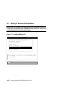
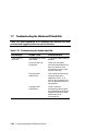
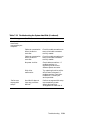
Download Compaq AlphaServer ES40 Specifications

Transcript
AlphaServer ES40
Owner’s Guide
Order Number: EK–ES240–UG. A01
This guide is intended for managers and operators of
AlphaServer ES40 systems.
Compaq Computer Corporation
First Printing, April 1999
The information in this publication is subject to change without notice.
COMPAQ COMPUTER CORPORATION SHALL NOT BE LIABLE FOR TECHNICAL
OR EDITORIAL ERRORS OR OMISSIONS CONTAINED HEREIN, NOR FOR
INCIDENTAL OR CONSEQUENTIAL DAMAGES RESULTING FROM THE
FURNISHING, PERFORMANCE, OR USE OF THIS MATERIAL. THIS
INFORMATION IS PROVIDED “AS IS” AND COMPAQ COMPUTER CORPORATION
DISCLAIMS ANY WARRANTIES, EXPRESS, IMPLIED OR STATUTORY AND
EXPRESSLY DISCLAIMS THE IMPLIED WARRANTIES OF MERCHANTABILITY,
FITNESS FOR PARTICULAR PURPOSE, GOOD TITLE AND AGAINST
INFRINGEMENT.
This publication contains information protected by copyright. No part of this publication
may be photocopied or reproduced in any form without prior written consent from
Compaq Computer Corporation.
© 1999 Digital Equipment Corporation.
All rights reserved. Printed in the U.S.A.
The software described in this guide is furnished under a license agreement or
nondisclosure agreement. The software may be used or copied only in accordance with
the terms of the agreement.
COMPAQ and the Compaq logo are registered in United States Patent and Trademark
Office. Tru64 is a trademark of Compaq Computer Corporation. AlphaServer and
OpenVMS are trademarks of Digital Equipment Corporation. UNIX is a registered
trademark in the U.S. and other countries, licensed exclusively through X/Open
Company Ltd.
Microsoft, Windows, and Windows NT are registered trademarks of Microsoft
Corporation.
Other product names mentioned herein may be the trademarks of their respective
companies.
Warning! This is a Class A product. In a domestic environment this product may cause
radio interference in which case the user may be required to take adequate measures.
Achtung! Dieses ist ein Gerät der Funkstörgrenzwertklasse A. In Wohnbereichen
können bei Betrieb dieses Gerätes Rundfunkstörungen auftreten, in welchen Fällen der
Benutzer für entsprechende Gegenmaßnahmen verantwortlich ist.
Attention! Ceci est un produit de Classe A. Dans un environnement domestique, ce
produit risque de créer des interférences radioélectriques, il appartiendra alors à
l'utilisateur de prendre les mesures spécifiques appropriées.
FCC Notice: This equipment generates, uses, and may emit radio frequency energy.
The equipment has been type tested and found to comply with the limits for a Class A
digital device pursuant to Part 15 of FCC rules, which are designed to provide reasonable
protection against such radio frequency interference.
Operation of this equipment in a residential area may cause interference in which case
the user at his own expense will be required to take whatever measures may be required
to correct the interference.
Any modifications to this device—unless expressly approved by the manufacturer—can
void the user’s authority to operate this equipment under part 15 of the FCC rules.
Contents
Preface
Chapter 1
1.1
1.2
1.3
1.4
1.5
1.6
1.7
1.8
1.9
1.10
1.11
1.12
System Overview
System Enclosures
System Chassis—Front View/Top View
System Chassis—Rear View
Rear Ports and Slots
Operator Control Panel
System Board
PCI Backplane
Power Supplies
Removable Media Storage
Hard Disk Storage
System Access
Console Terminal
Chapter 2
2.1
2.2
2.3
2.4
2.5
2.6
2.7
2.8
2.9
2.10
2.11
xi
1-2
1-4
1-5
1-6
1-8
1-10
1-12
1-14
1-16
1-17
1-18
1-20
Operation
Powering Up the System
Power-Up Displays
System Consoles
Displaying a Tru64 UNIX or OpenVMS Configuration
Setting SRM Environment Variables
Setting SRM Console Security
Displaying a Windows NT Hardware Configuration
Setting Up a System for Windows NT
Setting Automatic Booting
Changing the Default Boot Device
Running AlphaBIOS-Based Utilities
2-2
2-3
2-12
2-18
2-28
2-29
2-30
2-31
2-36
2-39
2-40
v
Chapter 3
3.1
3.2
3.3
3.4
3.5
3.6
3.7
3.8
Chapter 4
4.1
4.2
4.3
4.4
4.5
4.6
4.7
4.8
vi
3-2
3-8
3-12
3-14
3-18
3-20
3-22
3-24
Using the Remote Management Console
RMC Overview
Operating Modes
Terminal Setup
Entering the RMC
SRM Environment Variables for COM1
RMC Command-Line Interface
Resetting the RMC to Factory Defaults
Troubleshooting Tips
Chapter 5
5.1
5.2
5.3
5.4
5.5
5.6
5.7
5.8
5.9
5.10
5.11
5.12
5.13
5.14
5.15
5.16
Booting and Installing an Operating System
Setting Boot Options for UNIX or OpenVMS
Booting Tru64 UNIX
Starting a Tru64 UNIX Installation
Booting OpenVMS
Starting an OpenVMS Installation
Booting Windows NT
Starting a Windows NT Installation
Switching Between Operating Systems
4-2
4-4
4-9
4-10
4-12
4-13
4-29
4-31
Configuring and Installing Components
Removing Enclosure Panels
Removing Covers from the System Chassis
Hot-Plug Components
Power Supply Configuration
Removing and Replacing Power Supplies
Installing a Hard Drive
Non-Hot-Plug Components
CPU Configuration
Installing CPUs
Memory Configuration
Installing DIMMs
PCI Configuration
Installing PCI Cards
Installing a Removable Media Device
Installing a Second Disk Cage
External SCSI Expansion
5-2
5-6
5-9
5-10
5-12
5-14
5-16
5-18
5-20
5-23
5-26
5-30
5-32
5-35
5-38
5-41
Chapter 6
6.1
6.2
6.3
6.4
6.5
6.6
6.7
Chapter 7
7.1
7.2
7.3
7.4
7.5
7.6
7.7
6-2
6-4
6-6
6-7
6-9
6-10
6-12
Troubleshooting
Power-Up Error Messages
RMC Error Messages
SROM Error Messages
SRM Diagnostics
Troubleshooting Tables
Option Card Problems
Troubleshooting the Windows NT Hard Disk
Chapter 8
8.1
8.2
8.3
8.4
8.5
Updating Firmware
Sources of Firmware Updates
Firmware Update Utility
Manual Updates
Updating from the CD-ROM
Updating from an OpenVMS System Disk
OpenVMS and UNIX Network Boots
Upgrading AlphaBIOS over the Network
7-2
7-8
7-10
7-12
7-24
7-30
7-32
Specifications
Physical Specifications
Environmental Specifications
Electrical Specifications
Regulatory Approvals
Acoustical Data
8-2
8-6
8-7
8-8
8-9
Figures
1–1
1–2
1–3
1–4
1–5
1–6
1–7
1–8
1–9
1–10
1–11
1–12
2–1
Compaq AlphaServer ES40 Systems
Top/Front Components (Pedestal/Rack View)
Rear Components (Pedestal/Rack View)
Rear Connectors
Operator Control Panel
Modules on System Board
PCI Backplane (Pedestal/Rack View)
Power Supplies
Removable Media Drive Area
Hard Disk Storage Cage with Drives (Tower View)
System Keys
Console Terminal Connections
Operator Control Panel
1-2
1-4
1-5
1-6
1-8
1-10
1-12
1-14
1-16
1-17
1-18
1-20
2-2
vii
2–2
2–3
2–4
2–5
2–6
2–7
2–8
3–1
3–2
4–1
4–2
4–3
4–4
5–1
5–2
5–3
5–4
5–5
5–6
5–7
5–8
5–9
5–10
5–11
5–12
5–13
5–14
5–15
5–16
5–17
5–18
5–19
6–1
AlphaBIOS Setup Screen
Display System Configuration Screen
CMOS Setup Screen
Hard Disk Setup Screen
Advanced CMOS Setup Screen
AlphaBIOS Utilities Menu
Run Maintenance Program Dialog Box
AlphaBIOS Boot Screen
Installing Windows NT
Data Flow in Through Mode
Data Flow in Bypass Mode
Setup for RMC (Tower View)
RMC Jumpers (Default Positions)
Enclosure Panel Removal (Tower)
Enclosure Panel Removal (Pedestal)
Removing Covers from a Tower
Removing Covers from a Pedestal/Rack
Power Supply Locations
Installing a Power Supply (Pedestal/Rack View)
Installing a Hard Drive (Tower View)
CPU Slot Locations (Pedestal/Rack View)
CPU Slot Locations (Tower View)
CPU Card Installation (Pedestal/Rack View)
Memory Configuration (Pedestal/Rack View)
Memory Configuration (Tower View)
Installing DIMMs
Aligning DIMM in MMB
PCI Slot Locations (Pedestal/Rack)
PCI Slot Locations (Tower)
PCI Card Installation (Pedestal/Rack View)
Installing a 5.25-Inch Device (Pedestal/Rack View)
Installing a Second Disk Cage
AlphaBIOS Upgrade Screens
2-12
2-30
2-32
2-33
2-34
2-41
2-42
3-20
3-22
4-4
4-6
4-9
4-30
5-2
5-4
5-7
5-8
5-10
5-12
5-14
5-18
5-19
5-20
5-24
5-25
5-26
5-28
5-30
5-31
5-32
5-36
5-38
6-12
Tables
1
1–1
2–1
2–2
2–3
3–1
viii
Compaq AlphaServer ES40 Documentation
PCI Slot Mapping
Correspondence Between Logical and Physical PCI Slots
Device Naming Conventions
AlphaBIOS Option Key Mapping
OpenVMS Boot Flag Settings
xii
1-13
2-25
2-26
2-44
3-5
4–1
4–2
4–3
7–1
7–2
7–3
7–4
7–5
7–6
7–7
7–8
7–9
7–10
7–11
8–1
8–2
8–3
8–4
8–5
8–6
8–7
8–8
Status Command Fields
Elements of Dial String and Alert String
RMC Troubleshooting
Error Beep Codes
RMC Error Messages
SROM Error Messages
Bit Assignments for Error Field
Power Problems
Problems Getting to Console Mode
Problems Reported by the Console
Boot Problems
Errors Reported by the Operating System
Troubleshooting PCI Bus Problems
Troubleshooting the System Hard Disk
Physical Characteristics — Tower
Physical Characteristics — Pedestal
Physical Characteristics — System Chassis
Physical Characteristics — Cabinets
Environmental Characteristics — All System Variants
Electrical Characteristics — All System Variants
Regulatory Approvals
Acoustical Data
4-17
4-27
4-31
7-2
7-8
7-10
7-18
7-25
7-26
7-27
7-28
7-29
7-31
7-32
8-2
8-3
8-4
8-5
8-6
8-7
8-8
8-9
Examples
2–1
2–2
2–3
2–4
2–5
2–6
2–7
2–8
2–9
3–1
3–2
3–3
3–4
3–5
3–6
4–1
4–2
Sample SROM Power-Up Display
SRM Power-Up Display
AlphaBIOS Initialization Screen
AlphaBIOS Boot Screen
Set Ocp_Text Command
Show Boot*
Show Config
Show Device
Show Memory
Booting UNIX from a Local SCSI Disk
RIS Boot
Text-Based Installation Display
Booting OpenVMS from the Local CD-ROM Drive
InfoServer Boot
OpenVMS Installation Menu
Dial-In Configuration
Dial-Out Alert Configuration
2-4
2-6
2-10
2-11
2-17
2-19
2-20
2-26
2-27
3-8
3-10
3-12
3-14
3-16
3-18
4-22
4-24
ix
6–1
7–1
7–2
7–3
7–4
7–5
7–6
7–7
7–8
x
Update Utility Display
Checksum Error and Fail-Safe Load
Sample Console Event Log
Show Device Command
Test Command
Show Fru Command
Show Error Command
Show Power Command
Crash Command
6-4
7-4
7-12
7-13
7-14
7-16
7-19
7-20
7-22
Preface
Intended Audience
This manual is for system managers and operators of Compaq AlphaServer
ES40 systems.
Document Structure
This manual uses a structured documentation design. Topics are organized into
small sections, usually consisting of two facing pages. Most topics begin with an
abstract that provides an overview of the section, followed by an illustration or
example. The facing page contains descriptions, procedures, and syntax
definitions.
This manual has eight chapters.
•
Chapter 1, System Overview, gives an overview of the system and
describes the components.
•
Chapter 2, Operation, gives basic operating instructions on powering up
and configuring the machine.
•
Chapter 3, Booting and Installing an Operating System, describes
how to boot a supported operating system and how to switch from one
operating system to another.
•
Chapter 4, Using the Remote Management Console, describes the
function and operation of the integrated remote management console.
•
Chapter 5, Installing and Configuring Components, shows how to
install components.
•
Chapter 6, Updating Firmware, describes how to update to a later
version of system firmware.
•
Chapter 7, Troubleshooting, gives basic troubleshooting procedures.
•
Chapter 8, Specifications, gives system specifications.
xi
Documentation Titles
Table 1 Compaq AlphaServer ES40 Documentation
Title
Order Number
User Documentation Kit
Owner’s Guide
User Interface Guide
Tower and Pedestal Basic Installation
Release Notes
Documentation CD (6 languages)
QZ-01BAA-GZ
EK-ES240-UG
EK-ES240-UI
EK-ES240-PD
EK-ES240-RN
AG-RF9HA-BE
Maintenance Kit
Service Guide
Service Guide HTML Diskette
Illustrated Parts Breakdown
QZ-01BAB-GZ
EK-ES240-SV
AK-RFXDA-CA
EK-ES240-IP
Loose Piece Items
Rackmount Installation Guide
Rackmount Installation Template
EK-ES240-RG
Ek-ES4RM-TP
Support Resources
Support resources for this system are available on the Internet, including a
supported options list, firmware updates, and patches.
http://www.digital.com/alphaserver/technical.html
xii
Chapter 1
System Overview
This chapter provides an overview of the system, including:
•
System Enclosures
•
System Chassis—Front View/Top View
•
System Chassis—Rear View
•
Rear Ports and Slots
•
Operator Control Panel
•
System Board
•
PCI Backplane
•
Power Supplies
•
Removable Media Storage
•
Hard Disk Storage
•
System Access
•
Console Terminal
NOTE: See Chapter 5 for warnings and procedures for accessing internal parts
of the system.
System Overview
1-1
1.1
System Enclosures
The Compaq AlphaServer ES40 family consists of a standalone tower, a
pedestal with expanded storage capacity, and a rackmount system.
Figure 1–1 Compaq AlphaServer ES40 Systems
Rackmount
Pedestal
Tower
PK0212
1-2
Compaq AlphaServer ES40 Owner’s Guide
Common Components
The basic building block of the system is the chassis, which houses the following
common components:
•
Up to four CPUs, based on the 21264 Alpha chip
•
Memory DIMMs (200-pin); up to 16 or up to 32
•
Six or ten 64-bit PCI slots
•
Floppy diskette drive (3.5-inch, high density)
•
CD-ROM drive
•
Two half-height or one full-height removable media bays
•
Up to two storage disk cages that house up to four 1.6-inch drives per cage
•
Up to three 735-watt power supplies, offering N+1 power
•
A 25-pin parallel port, two 9-pin serial ports, two universal serial bus (USB)
ports, mouse and keyboard ports, and one MMJ connector for a local console
terminal
•
An operator control panel with a 16-character back-lit display and a Power
button, Halt button, and Reset button
System Overview
1-3
1.2
System Chassis—Front View/Top View
Figure 1–2 Top/Front Components (Pedestal/Rack View)
8
7
6
4
1
9
3
6
2
5
PK0201
➊
➋
➌
➍
➎
➏
➐
➑
➒
Operator control panel
1-4
Compaq AlphaServer ES40 Owner’s Guide
CD-ROM drive
Removable media bays
Floppy diskette drive
Storage drive bays
Fans
CPUs
Memory
PCI cards
1.3
System Chassis—Rear View
Figure 1–3 Rear Components (Pedestal/Rack View)
3
2
1
PK0206
➊
➋
➌
Power supplies
PCI bulkhead
I/O ports
System Overview
1-5
1.4
Rear Ports and Slots
Figure 1–4 Rear Connectors
Pedestal/
Rack
1
2
3
4
5
6
7
9
8
10
9
1
10
2
3
4
5
6
8
Tower
1-6
Compaq AlphaServer ES40 Owner’s Guide
7
PK0209
Rear Panel Connections
➊
Modem port—Dedicated 9-pin port for modem connection to remote
management console.
➋
➌
➍
➎
COM2 serial port—Extra port to modem or any serial device.
➏
➐
➑
➒
USB ports.
➓
PCI slot for VGA controller, if installed.
Keyboard port—To PS/2-compatible keyboard.
Mouse port—To PS/2-compatible mouse.
COM1 MMJ-type serial port/terminal port—For connecting a console
terminal.
Parallel port—To parallel device such as a printer.
SCSI breakouts.
PCI slots—For option cards for high-performance network, video, or disk
controllers.
System Overview
1-7
1.5
Operator Control Panel
The control panel provides system controls and status indicators. The
controls are the Power, Halt, and Reset buttons. A 16-character backlit alphanumeric display indicates system state. The panel has two
LEDs: a green Power OK indicator and an amber Halt indicator.
Figure 1–5 Operator Control Panel
1
2
3
4
5
6
PK0204
➊ Control panel display. A one-line, 16-character alphanumeric display that
indicates system status during power-up and testing. During operation, the
control panel is back lit.
➋ Power button. Powers the system on and off.
If a failure occurs that causes the system to shut down, pressing the power
button off and then on clears the shutdown condition and attempts to power
the system back on. Some conditions that prevent the system from
powering on can be determined by entering the env command from the
remote management console (RMC). The RMC is powered separately from
the rest of the system and can operate as long as AC power is present. (See
Chapter 4.)
1-8
Compaq AlphaServer ES40 Owner’s Guide
➌ Power LED (green). Lights when the power button is pressed.
➍ Reset button. A momentary contact switch that restarts the system and
reinitializes the console firmware. Power-up messages are displayed, and
then the console prompt is displayed or the operating system boot messages
are displayed, depending on how the startup sequence has been defined.
➎ Halt LED (amber). Lights when you press the Halt button.
➏ Halt button. Halts the system.
If Tru64 UNIX or OpenVMS is running, pressing the Halt button halts the
operating system and returns to the SRM console. Pressing the Halt button
does not halt the Windows NT operating system.
If the Halt button is latched when the system is reset or powered up, the
system halts in the SRM console, regardless of the operating system. UNIX
and OpenVMS systems that are configured to autoboot cannot boot until the
Halt button is unlatched.
Commands issued from the remote management console (RMC) can be used to
reset, halt, and power the system on or off. For information on RMC, see
Chapter 4.
RMC Command
Function
Power {off, on}
Equivalent to pressing the Power button on the control panel
to the ON or OFF position.
Halt {in, out}
Equivalent to pressing the Halt button on the control panel
to cause a halt (halt in) or releasing it from the latched
position to deassert the halt (halt out).
Reset
Equivalent to pressing the Reset button on the control panel.
System Overview
1-9
1.6
System Board
The system board is located on the floor of the system card cage. It has
slots for the CPUs and memory motherboards (MMBs).
The system board has the majority of the logic for the system. It holds the CPU
cards and MMBs. Figure 1–6 shows the location of these modules on the
system board.
Figure 1–6 Modules on System Board
J7
MMB1
J17
CPU3
J8
MMB3
J18
CPU2
J5
MMB0
J34
CPU1
MMB2
J40
J6
CPU0
PK0214
1-10
Compaq AlphaServer ES40 Owner’s Guide
CPU Card
The system can have up to four CPU cards. The CPU cards are installed on the
system board. Each CPU card contains a 21264 microprocessor, the thirdgeneration implementation of the Alpha architecture.
The 21264 microprocessor is a superscalar CPU with out-of-order execution and
speculative execution to maximize speed and performance. It contains four
integer execution units and dedicated execution units for floating-point add,
multiply, and divide. It has an instruction cache and a data cache on the chip.
Each cache is a 64 KB, two-way, set-associative, virtually addressed cache that
has 64-byte blocks. The data cache is a physically tagged, write-back cache.
Each CPU card has a 4 MB secondary B-cache (backup cache) consisting of latewrite synchronous static RAMs (SRAMs) that provide low latency and high
bandwidth. Each CPU card also has a 5 ->2 volt power regulator that supplies
up to 100 watts at 2.2 volts to the CPU.
See Chapter 5 for instructions on installing additional CPUs.
Memory Motherboards (MMBs)
Memory is installed into memory motherboards (MMBs) located on the system
board. There are four MMBs. The MMBs have either four or eight slots for
installing DIMMs. The system memory uses JEDEC standard 200-pin
synchronous DIMMs.
See Chapter 5 for memory configuration rules and installation instructions.
System Overview
1-11
1.7
PCI Backplane
The PCI backplane has two 64-bit, 33 MHz PCI buses that support 64-bit
PCI slots. The 64-bit PCI slots are split across two independent 64-bit,
33 MHz PCI buses. The PCI buses support 3.3 V or 5 V options. Figure
1–7 shows the location of the PCI slots in a 6-slot system and a 10-slot
system.
Figure 1–7 PCI Backplane (Pedestal/Rack View)
1
2
10-Slot
3
System
4
5
6
7
8
9
10
6-Slot
System
1
2
3
8
9
10
1-12
Compaq AlphaServer ES40 Owner’s Guide
PK0226
Table 1–1 shows the correspondence between the physical locations of the slots
on the PCI backplane and the logical numbering reported with the SRM console
show config command (described in Chapter 2). See Chapter 5 for instructions
on installing PCI options.
Table 1–1 PCI Slot Mapping
Physical Slot
Logical Slot
PCI 0
1
1
Device
2
2
Device
3
3
Device
4
4
Device
Physical Slot
Logical Slot
PCI 1
5
1
Device
6
2
Device
7
3
Device
8
4
Device
9
5
Device
10
6
Device
NOTE: PCI 0 and PCI 1 correspond to Hose 0 and Hose 1 in the logical
configuration. On a six-slot system, physical slots 4–7 do not apply.
System Overview
1-13
1.8
Power Supplies
The power supplies provide power to components in the system
chassis. The number of power supplies required depends on the system
configuration.
Figure 1–8 Power Supplies
Tower
0
1
1
2
2
Pedestal/Rack
0
1
2
PK0207
1-14
Compaq AlphaServer ES40 Owner’s Guide
One to three power supplies provide power to components in the system chassis.
The system supports redundant power configurations to ensure continued
system operation if a power supply fails.
When more than one power supply is installed, the supplies share the load. The
power supplies select line voltage and frequency automatically (100 V or 120 V
or 200–240 V and 50 Hz or 60 Hz).
Power Supply LEDs
Each power supply has two green LEDs that indicate the state of power to the
system.
➊ POK (Power OK)
Indicates that the power supply is functioning. The POK
LED is on when the system is running. When the
system power is on and a POK LED is off, that supply is
not contributing to powering the system.
➋ +5 V Auxiliary
Indicates that AC power is flowing from the wall outlet.
As long as the power supply cord is plugged into the wall
outlet, the +5V Aux LED is always on, even when the
system power is off.
See Chapter 5 for instructions on installing additional power supplies.
System Overview
1-15
1.9
Removable Media Storage
The system chassis houses a CD-ROM drive ➊ and a high-density 3.5inch floppy diskette drive ➋ and supports two additional 5.25-inch halfheight drives or one additional full-height drive. The 5.25-inch half
height area has a divider that can be removed to mount one full-height
5.25-inch device.
See Chapter 5 for information on installing a removable media drive.
Figure 1–9 Removable Media Drive Area
2
1
PK0233
1-16
Compaq AlphaServer ES40 Owner’s Guide
1.10 Hard Disk Storage
The system chassis can have either one or two storage disk cages.
You can install four 1.6-inch hard drives in each storage disk cage. See
Chapter 5 for information on installing hard disk drives.
Figure 1–10 Hard Disk Storage Cage with Drives (Tower View)
PK0935
System Overview
1-17
1.11 System Access
At the time of delivery, the system keys are taped inside the small front
door that provides access to the operator control panel and removable
media devices.
Figure 1–11 System Keys
Tower
Pedestal
1-18
Compaq AlphaServer ES40 Owner’s Guide
PK0224
Both the tower and pedestal systems have a small front door through which
the control panel and removable media devices are accessible. At the time of
delivery, the system keys are taped inside this door.
The tower front door has a lock that lets you secure access to the disk drives and
to the rest of the system.
The pedestal has two front doors, both of which can be locked. The upper door
secures the disk drives and access to the rest of the system, and the lower door
secures the expanded storage.
NOTE: See Chapter 5 for warnings and procedures for accessing internal parts
of the system.
System Overview
1-19
1.12 Console Terminal
The console terminal can be a serial (character cell) terminal
connected to the COM1 or COM2 port or a VGA monitor connected to a
VGA adapter on PCI 0. A VGA monitor requires a keyboard and mouse.
Figure 1–12 Console Terminal Connections
VT
Tower
VT
Pedestal/Rack
1-20
Compaq AlphaServer ES40 Owner’s Guide
PK0225
Chapter 2
Operation
This chapter gives basic operating instructions, including powering up and
configuring the machine. This chapter has the following sections:
•
Powering Up the System
•
Power-Up Displays
•
System Consoles
•
Displaying a UNIX or OpenVMS Configuration
•
Setting SRM Environment Variables
•
Setting SRM Console Security
•
Displaying a Windows NT Hardware Configuration
•
Setting Up a System for Windows NT
•
Setting Automatic Booting
•
Changing the Default Boot Device
•
Running AlphaBIOS-Based Utilities
NOTE: Before using this chapter, it is helpful to become familiar with the user
interfaces to the system. See the Compaq AlphaServer ES40 User
Interface Guide.
Operation
2-1
2.1
Powering Up the System
To power up the system, press the power button. Testing begins, and
status shows on the console terminal screen and in the control panel
display.
Figure 2–1 Operator Control Panel
2
1
PK0204A
➊
➋
2-2
Power button
Control panel display
Compaq AlphaServer ES40 Owner’s Guide
2.2
Power-Up Displays
Power-up information is displayed on the operator control panel and
on the console terminal startup screen. Messages sent from the SROM
(serial read-only memory) program are displayed first, followed by
messages from the SRM console.
NOTE: The power-up text that is displayed on the screen depends on what kind
of terminal is connected as the console terminal: VT or VGA.
If the SRM console environment variable is set to serial, the entire
power-up display, consisting of the SROM and SRM power-up
messages, is displayed on the VT terminal screen. If console is set to
graphics, no SROM messages are displayed, and the SRM messages
are delayed until VGA initialization has been completed.
•
Section 2.2.1 shows the SROM power-up messages and corresponding
operator control panel (OCP) messages.
•
Section 2.2.2 shows the messages that are displayed once the SROM has
transferred control to the SRM console.
•
For a complete list of messages displayed on the OCP, see Chapter 7.
Operation
2-3
2.2.1
SROM Power-Up Display
Example 2–1 Sample SROM Power-Up Display
SROM Power-Up Display
SROM V1.00 CPU #00 @ 0500
SROM program starting
Reloading SROM
OCP Message
MHz
SROM T1.5-F CPU # 00 @ 0500 MHz
SROM program starting
Starting secondary on CPU #1
Starting secondary on CPU #2
Starting secondary on CPU #3
Bcache data tests in progress
Bcache address test in progress
CPU parity and ECC detection in progress
Bcache ECC data tests in progress
Bcache TAG lines tests in progress
Memory sizing in progress
Memory configuration in progress
Memory data test in progress
Memory address test in progress
Memory pattern test in progress
Memory thrashing test in progress
Memory initialization
Loading console
Code execution complete (transfer control)
2-4
Compaq AlphaServer ES40 Owner’s Guide
PCI Test
Power on
➊
➋
RelCPU
➌
BC Data
➍
Size Mem
➎
Load ROM
Jump to
Console
➏
➊
When the system powers up, the SROM code is loaded into the I-cache
(instruction cache) on the first available CPU, which becomes the primary
CPU. The order of precedence is CPU0, CPU1, and so on. The primary
CPU attempts to access the PCI bus. If it cannot, either a hang or a failure
occurs, and this is the only message displayed.
➋
The primary CPU interrogates the I C EEROM on the system board and
CPU modules through shared RAM. The primary CPU determines the
CPU and system configuration to jump to.
2
The primary CPU next checks the SROM checksum to determine the
validity of the flash SROM sectors.
If flash SROM is invalid, the primary CPU reports the error and continues
the execution of the SROM code. Invalid flash SROM must be
reprogrammed.
If flash SROM is good, the primary CPU programs appropriate registers
with the values from the flash data and selects itself as the target CPU to
be loaded.
➌
The primary CPU (usually CPU0) initializes and tests the B-cache and
memory, then loads the flash SROM code to the next CPU. That CPU then
initializes the EV6 (21264 chip) and marks itself as the secondary CPU.
Once the primary CPU sees the secondary, it loads the flash SROM code to
the next CPU until all remaining CPUs are loaded.
➍
The flash SROM performs B-cache tests. For example, the ECC data test
verifies the detection logic for single- and double-bit errors.
➎
The primary CPU initiates all memory tests. The memory is tested for
address and data errors for the first 32 MB of memory. It also initializes
all the “sized” memory in the system.
If a memory failure occurs, an error is reported. An untested memory
array is assigned to address 0 and the failed memory array is deassigned.
The memory tests are re-run on the first 32 MB of memory. If all memory
fails, the “No Memory Available” message is reported and the system halts.
➏
If all memory passes, the primary CPU loads the console and transfers
control to it.
Operation
2-5
2.2.2
SRM Console Power-Up Display
At the completion of SROM power-up, the primary CPU transfers
control to the SRM console program. The console program continues
the system initialization. Failures are reported to the console terminal
through the power-up screen and a console event log.
Example 2–2 SRM Power-Up Display
OpenVMS PALcode V1.50-0,
Tru64 UNIX PALcode V1.45-5
➊
starting console on CPU 0
initialized idle PCB
initializing semaphores
initializing heap
initial heap 200c0
memory low limit = 144000
heap = 200c0, 17fc0
initializing driver structures
initializing idle process PID
initializing file system
initializing hardware
initializing timer data structures
lowering IPL
CPU 0 speed is 2.00 ns (500MHz)
create dead_eater
create poll
create timer
create powerup
access NVRAM
Memory size 2048 MB
testing memory
➋
...
probe I/O subsystem
➌
probing hose 1, PCI
bus 0, slot 2, function 0 -- pka -- NCR 53C896
bus 0, slot 2, function 1 -- pkb -- NCR 53C896
bus 0, slot 4 -- ewa -- DE500-AA Network Controller
probing hose 0, PCI
probing PCI-to-ISA bridge, bus 1
bus 0, slot 2 -- vga -- DEC PowerStorm
bus 0, slot 15 -- dqa -- Acer Labs M1543C IDE
bus 0, slot 15 -- dqb -- Acer Labs M1543C IDE
starting drivers
➍
2-6
Compaq AlphaServer ES40 Owner’s Guide
➊ The primary CPU prints a message indicating that it is running the console.
Starting with this message, the power-up display is sent to any console
terminal, regardless of the state of the console environment variable.
If console is set to graphics, the display from this point on is saved in a
memory buffer and displayed on the VGA monitor after the PCI buses are
sized and the VGA device is initialized.
➋ The memory size is determined and memory is tested.
➌ The I/O subsystem is probed and I/O devices are reported. I/O adapters are
configured.
➍ Device drivers are started.
Continued on next page
Operation
2-7
Example 2–2 SRM Power-Up Display (Continued)
entering idle loop
initializing keyboard
starting console on CPU 1
initialized idle PCB
initializing idle process PID
lowering IPL
CPU 1 speed is 2.00 ns (500MHz)
create powerup
entering idle loop
starting console on CPU 2
initialized idle PCB
initializing idle process PID
lowering IPL
CPU 2 speed is 2.00 ns (500MHz)
create powerup
starting console on CPU 3
initialized idle PCB
initializing idle process PID
lowering IPL
CPU 3 speed is 2.00 ns (500MHz)
create powerup
Memory Testing and Configuration Status
Array
Size
Base Address
--------- ---------- ---------------0
256Mb
0000000060000000
1
512Mb
0000000040000000
2
256Mb
0000000070000000
3
1024Mb
0000000000000000
2048 MB of System Memory
Testing the System
Testing the Disks (read only)
Testing the Network
initializing GCT/FRU at offset 192000
AlphaServer ES40 Console V5.4-5528, built on Feb
01:43:35
P00>>>
2-8
Compaq AlphaServer ES40 Owner’s Guide
➎
➏
1 1999 at
➐
➎ The console is started on the secondary CPUs. The example shows a fourprocessor system.
➏ Various diagnostics are performed.
➐ Systems running UNIX or OpenVMS display the SRM console banner and
the prompt, Pnn>>>. The number n indicates the primary processor. In a
multiprocessor system, the prompt could be P00>>>, P01>>>, P02>>>, or
P03>>>. From the SRM prompt, you can boot the UNIX or OpenVMS
operating system.
Operation
2-9
2.2.3
AlphaBIOS Startup Screens
If the system is running the Windows NT operating system, the SRM
console loads and starts the AlphaBIOS console. An initialization
screen similar to Example 2–3 is displayed on the VGA monitor. Once
AlphaBIOS initialization is complete, an AlphaBIOS boot screen similar
to Example 2–4 is displayed.
Example 2–3 AlphaBIOS Initialization Screen
AlphaBIOS 5.68
Alpha Processor and System Information:
System:
AlphaServer ES40
Processor:
Alpha 21264, 500 MHz
Memory:
256 MB
Alpha Processor(s) Status:
Processor 0 Running
Processors 1, 2, 3 Ready
SCSI Controller Initialization...
Initialize ATAPI #0...
Device: CD-ROM SCSI ID:0 TOSHIBA CD-ROM XM62028 1110
F2=Setup
PAUSE=Pause Display
ESC=Bypass Network Init
PKO950
2-10
Compaq AlphaServer ES40 Owner’s Guide
Example 2–4 AlphaBIOS Boot Screen
AlphaBIOS 5.68
Please select the operating system to start:
Windows NT Server 4.00
Use
and
to move the highlight to your choice.
Press Enter to choose.
AlphaServer
Press <F2> to enter SETUP
PK0949
Operation
2-11
2.3
System Consoles
System console programs are located in a flash ROM (read-only
memory) on the system board. From the console interface, you can set
up and boot the operating system, display the system configuration,
and perform other tasks. For complete information on the SRM and
AlphaBIOS consoles, see the Compaq AlphaServer ES40 User Interface
Guide.
Figure 2–2 AlphaBIOS Setup Screen
AlphaBIOS Setup
Display System Configuration...
AlphaBIOS Upgrade...
Hard Disk Setup...
CMOS Setup...
Network Setup...
Install Windows NT
Utilities
About AlphaBIOS...
Press ENTER to partition or format hard disks.
ESC=Exit
PK0905
2-12
Compaq AlphaServer ES40 Owner’s Guide
SRM Console
Systems running the Tru64 UNIX or OpenVMS operating systems are
configured from the SRM console, a command-line interface (CLI). From the
CLI you can enter commands to configure the system, view the system
configuration, and boot the system.
For example, to verify that the system sees the bootable devices that are
attached, enter:
P00>>> show device
AlphaBIOS Console
Systems running the Windows NT operating system are configured from the
AlphaBIOS console, a menu interface. From the AlphaBIOS boot screen, you
can boot the operating system or press F2 to enter a setup screen to set up the
system. See Figure 2–2.
Operation
2-13
2.3.1
Switching Between Consoles
Under some circumstances, you may need to switch between the system
consoles.
For example, RAID devices are configured from the
AlphaBIOS console.
•
To enter the SRM console from Windows NT, press the Reset button, then
press the Halt button. You can also enter SRM by changing the Console
Selection option on the AlphaBIOS Advanced CMOS Setup screen. See the
Compaq AlphaServer ES40 User Interface Guide for details.
•
To enter the AlphaBIOS console from SRM, issue the alphabios command:
P00>>> alphabios
2-14
Compaq AlphaServer ES40 Owner’s Guide
2.3.2
Selecting the Console and Display Device
The SRM os_type environment variable determines which user
interface (SRM or AlphaBIOS) is the final console loaded on a power-up
or reset. The SRM console environment variable determines to which
display device (VT-type terminal or VGA monitor) the console display is
sent.
Selecting the Console
The os_type variable selects the console. Os_type is factory configured as
follows:
•
For Windows NT, os_type is set to nt.
•
For UNIX or OpenVMS, os_type is set to unix or vms, respectively.
If os_type is set to unix or vms, the SRM console is loaded on a power-up or
reset. If os_type is set to nt, the SRM console is loaded and then SRM starts
the AlphaBIOS console from system flash ROM.
Selecting the Display Device
The console terminal that displays the SRM user interface can be either a serial
terminal (VT320 or higher, or equivalent) or a VGA monitor. A VGA monitor is
required to run Windows NT.
The SRM console environment variable determines the display device.
•
If console is set to serial, and a VT-type device is connected, the SRM
console powers on in serial mode and sends power-up information to the VT
device. The VT device can be connected to the MMJ port or to COM2.
•
If console is set to graphics, the SRM console expects to find a VGA card
connected to PCI 0 and, if so, displays power-up information on the VGA
monitor after VGA initialization has been completed.
Continued on next page
Operation
2-15
You can verify the display device with the SRM show console command and
change the display device with the SRM set console command. If you change
the display device setting, you must reset the system (with the Reset button or
the init command) to put the new setting into effect.
In the following example, the user displays the current console device (a
graphics device) and then resets it to a serial device. After the system
initializes, output will be displayed on the serial terminal.
P00>>> show console
console
graphics
P00>>> set console serial
P00>>> init
.
.
.
2-16
Compaq AlphaServer ES40 Owner’s Guide
2.3.3
Setting the Control Panel Message
If you are running Tru64 UNIX or OpenVMS, you can create a
customized message to be displayed on the operator control panel after
startup self-tests and diagnostics have been completed.
When the operating system is running, the control panel displays the console
revision. It is useful to create a customized message if you have a number of
systems and you want to identify each system by a node name.
You can use the SRM set ocp_text command to change this message (see
Example 2–5). The message can be up to 16 characters and must be entered in
quotation marks.
Example 2–5 Set Ocp_Text Command
P00>>> set ocp_text “Node Alpha1”
Operation
2-17
2.4 Displaying a Tru64 UNIX or OpenVMS
Configuration
View the system hardware configuration for UNIX and OpenVMS
systems from the SRM console.
View a Windows NT hardware
configuration from the AlphaBIOS console. It is useful to view the
hardware configuration to ensure that the system recognizes all
devices, memory configuration, and network connections.
Use the following SRM console commands to view the system configuration for
UNIX or OpenVMS systems. Additional commands to view the system
configuration are described in the Compaq AlphaServer ES40 User Interface
Guide.
show boot*
Displays the boot environment variables.
show config
Displays the logical configuration of interconnects and buses
on the system and the devices found on them.
show device
Displays the bootable devices and controllers in the system.
show fru
Displays the physical configuration of FRUs (field-replaceable
units). See Chapter 7 for information on this command.
show memory
Displays configuration of main memory.
2-18
Compaq AlphaServer ES40 Owner’s Guide
2.4.1
Displaying Boot Environment Variables
Use the show boot* command to list the boot environment variables.
Example 2–6 Show Boot*
P00>>> show boot*
boot_dev
boot_file
boot_osflags
boot_reset
bootdef_dev
booted_dev
booted_file
booted_osflags
dka0.0.0.1.1
a
OFF
dka0.0.0.1.1
Operation
2-19
2.4.2
Displaying the Logical Configuration
Use the show config command to display the logical configuration. To
display the physical configuration, issue the show fru command.
Example 2–7 Show Config
P00>>> show config
Compaq Computer Corporation
Compaq AlphaServer ES40
➊
Firmware
SRM Console:
ARC Console:
PALcode:
Serial Rom:
RMC Rom:
RMC Flash Rom:
V5.4-5528
5.68
OpenVMS PALcode V1.50-0, Tru64 UNIX PALcode V1.47-5
V1.5-F
V1.0
V1.2
Processors
CPU 0
CPU 1
CPU 2
CPU 3
Alpha
Alpha
Alpha
Alpha
Core Logic
Cchip
Dchip
Pchip 0
Pchip 1
TIG
DECchip
DECchip
DECchip
DECchip
Rev 10
Memory
Array
--------0
1
2
3
➋
21264-4
21264-4
21264-4
21264-4
500
500
500
500
MHz
MHz
MHz
MHz
4MB
4MB
4MB
4MB
Bcache
Bcache
Bcache
Bcache
➌
21272-CA
21272-DA
21272-EA
21272-EA
Rev
Rev
Rev
Rev
9(C4)
2
2
2
➍
Size
---------256Mb
512Mb
256Mb
1024Mb
Base Address
---------------0000000060000000
0000000040000000
0000000070000000
0000000000000000
2048 MB of System Memory
Continued on next page
2-20
Compaq AlphaServer ES40 Owner’s Guide
➊
Firmware. Version numbers of the SRM console, AlphaBIOS (ARC)
console, PALcode, serial ROM, RMC ROM, and RMC flash ROM
➋
Processors. Processors present, processor version and clock speed, and
amount of backup cache
➌
Core logic. Version numbers of the chips that form the interconnect on
the system board
➍
Memory. Memory arrays and memory size
Continued on next page
Operation
2-21
Example 2–7 Show Config (Continued)
Slot
2/0
2/1
4
7
15
Option
NCR 53C896
NCR 53C896
DEC PowerStorm
Acer Labs M1543C
Acer Labs M1543C IDE
19
Acer Labs M1543C USB
Option
Floppy
Slot Option
1
NCR 53C895
Hose 0, Bus 0, PCI
➎
pke0.7.0.2.0
SCSI Bus ID 7
pkf0.7.0.102.0
SCSI Bus ID 7
Bridge to Bus 1, ISA
dqa.0.0.15.0
dqb.0.1.15.0
dqa0.0.0.15.0
TOSHIBA CD-ROM XM-6302B
Hose 0, Bus 1, ISA
dva0.0.0.1000.0
3
NCR 53C810
4
6
DE500-BA Network Con
DECchip 21152-AA
Hose 1, Bus 0, PCI
pka0.7.0.1.1
SCSI Bus ID 7
dka0.0.0.1.1
RZ2DD-LS
dka100.1.0.1.1
RZ2DD-LS
dka200.2.0.1.1
RZ1CB-CS
pkb0.7.0.3.1
SCSI Bus ID 7
dkb0.0.0.3.1
RZ25
ewa0.0.0.4.1
00-00-F8-09-90-FF
Bridge to Bus 2, PCI
Option
NCR 53C875
NCR 53C875
DE500-AA Network Con
Hose 1, Bus 2, PCI
pkc0.7.0.2000.1
SCSI Bus ID 7
pkd0.7.0.2001.1
SCSI Bus ID 7
ewb0.0.0.2002.1
00-06-2B-00-25-5B
Slot
0
1
2
P00>>>
2-22
Compaq AlphaServer ES40 Owner’s Guide
➎
PCI bus information.
The “Slot” column lists the logical slots seen by the system. These are not
the physical slots into which devices are installed. See Table 2–1 for the
correspondence between logical slots and physical slots.
The NCR 53C896 on Hose 0, Bus 0 is a dual-channel Ultra2 SCSI
multifunction controller. Two controllers reside on the same chip. They
are shown as 2/0 and 2/1. The first number is the logical slot, and the
second is the function.
The Acer Labs bridge chip, which is located in PCI logical slot 7, has two
built-in IDE controllers. The CD-ROM is on the first controller.
NOTE: The naming of devices (for example,dqa.0.0.15.0) follows the
conventions described in Table 2–2.
In Example 2–7, the following devices are present:
Hose 0, Bus 0, PCI
Slot 2/0
SCSI controller
Slot 2/1
SCSI controller
Slot 4
VGA controller
Slot 7
PCI to ISA bridge chip
Slot 15
IDE controller and CD-ROM drive
Slot 19
Universal serial bus (USB) controller
Hose 0, Bus 1, ISA
Diskette drive
Hose 1, Bus 0, PCI
Slot 1
SCSI controller and drives
Slot 3
SCSI controller and drives
Slot 4
Ethernet controller
Slot 6
PCI-to-PCI bridge chip to Bus 2
Hose 1, Bus 2, PCI
Slot 0
SCSI controller
Slot 1
SCSI controller
Slot 2
Ethernet controller
Continued on next page
Operation
2-23
Table 2–1 Correspondence Between Logical and Physical PCI Slots
Physical Slot
Logical Slot
PCI 0
1
2
3
4
1
2
3
4
Device
Device
Device
Device
Physical Slot
Logical Slot
PCI 1
5
6
7
8
9
10
1
2
3
4
5
6
Device
Device
Device
Device
Device
Device
NOTE: PCI 0 and PCI 1 correspond to Hose 0 and Hose 1 in the logical
configuration.
2-24
Compaq AlphaServer ES40 Owner’s Guide
2.4.3
Displaying the Bootable Devices
Use the show device command to display the bootable devices. DK =
SCSI drive; DQ = IDE drive; DV = diskette drive; EI or EW = Ethernet
controller; PK = SCSI controller.
Example 2–8 Show Device
P00>>> show device
dka0.0.0.1.1
dka100.1.0.1.1
dka200.2.0.1.1
dkb0.0.0.3.1
dqa0.0.0.15.0
dva0.0.0.1000.0
ewa0.0.0.4.1
ewb0.0.0.2002.1
pka0.7.0.1.1
pkb0.7.0.3.1
pkc0.7.0.2000.1
pkd0.7.0.2001.1
DKA0
DKA100
DKA200
DKB0
DQA0
DVA0
EWA0
EWB0
PKA0
PKB0
PKC0
PKD0
RZ2DD-LS
RZ2DD-LS
RZ1CB-CS
RZ25
TOSHIBA CD-ROM XM-6302B
0306
0306
0844
0900
1012
00-00-F8-09-90-FF
00-06-2B-00-25-5B
SCSI Bus ID 7
SCSI Bus ID 7
SCSI Bus ID 7
SCSI Bus ID 7
Table 2–2 Device Naming Conventions
Category
Description
dq
Driver ID
a
Storage adapter ID
0
Device unit number
0
0
15
0
Bus node number
Channel number
Logical slot number
Hose number
Two-letter designator of port or class driver
dk
SCSI drive or CD
ew
Ethernet port
dq
IDE CD-ROM
fw
FDDI device
dr
RAID set device
mk
SCSI tape
du
DSSI disk
mu
DSSI tape
dv
Diskette drive
pk
SCSI port
ei
Ethernet port
pu
DSSI port
One-letter designator of storage adapter
(a, b, c…).
Unique number (MSCP unit number). SCSI unit numbers
are forced to 100 X node ID.
Bus node ID.
Used for multi-channel devices.
Corresponds to PCI slot number, as shown in Table 2–1.
0 — PCI 0
1 — PCI 1
Operation
2-25
2.4.4
Viewing Memory Configuration
Use the show memory command to view the configuration of main
memory.
Example 2–9 Show Memory
P00>>> show memory
Array
Size
--------- ---------0
256Mb
1
512Mb
2
256Mb
3
1024Mb
Base Address
---------------0000000060000000
0000000040000000
0000000070000000
0000000000000000
2048 MB of System Memory
The show memory display corresponds to the memory array configuration
described in Chapter 5. The display does not indicate the number of DIMMs or
their size. Thus, in Example 2–9, Array 3 could consist of two sets of 128-MB
DIMMs (eight DIMMs) or one set of 256-MB DIMMs (four DIMMs). Either
combination provides 1024 MB of memory.
Use the show fru command to display the DIMMs in the system and their
location. See Chapter 7.
2-26
Compaq AlphaServer ES40 Owner’s Guide
2.5
Setting SRM Environment Variables
You may need to set several SRM console environment variables and
built-in utilities to configure systems running the Tru64 UNIX or
OpenVMS operating systems.
Set environment variables at the P00>>> prompt.
•
To check the setting for a specific environment variable, enter the show
envar command, where the name of the environment variable is
substituted for envar.
•
To reset an environment variable, use the set envar command, where the
name of the environment variable is substituted for envar.
The boot-related environment variables are described in Chapter 3 of this book.
For other environment variables you may need to set, see Chapter 2 in the
Compaq AlphaServer ES40 User Interface Guide.
Operation
2-27
2.6
Setting SRM Console Security
You can set the SRM console to secure mode to prevent unauthorized
personnel from modifying the system parameters or otherwise
tampering with the system from the console.
When the SRM is set to secure mode, you can use only two console commands:
•
The boot command, to boot the operating system
•
The continue command, to resume running the operating system if you
have inadvertently halted the system
The console security commands are as follows:
set password
set secure
These commands put the console into secure mode.
clear password
Exits secure mode.
login
Turns off console security for the current session.
See the Compaq AlphaServer ES40 User Interface Guide for details on setting
SRM console security.
2-28
Compaq AlphaServer ES40 Owner’s Guide
2.7
Displaying a Windows NT Hardware Configuration
View a Windows NT configuration from AlphaBIOS.
1. From the AlphaBIOS Setup screen, select Display System Configuration
and press Enter.
2. In the Display System Configuration screen, use the arrow keys to select the
configuration category you want.
Figure 2–3 Display System Configuration Screen
Display System Configuration
Systemboard Configuration
Hard Disk Configuration
PCI Configuration
SCSI Configuration
Memory Configuration
Integrated Peripherals
System Type:
Processor:
Speed:
Cache:
Memory:
AlphaServer ES40
Digital Alpha 21264, Revision 4.0 (4 Processors)
500 MHz
4 MB
2048 MB
Floppy Drive A:
Floppy Drive B:
Keyboard:
3.5" 1.44 MB
None
U.S. 101-key keyboard
AlphaBIOS Version:
5.68
ESC=Exit
PK0902
Operation
2-29
2.8
Setting Up a System for Windows NT
Before you boot Windows NT, set the system date and time and set up
the hard disks. Optionally, you can set the level of memory testing and
set up system password protection.
If you are installing Windows NT from CD-ROM, use the AlphaBIOS CMOS
Setup screen and the Hard Disk Setup screen to set up your system. Use the
Advanced CMOS Setup screen to set the level of memory testing and to set
password protection, if desired.
2-30
Compaq AlphaServer ES40 Owner’s Guide
2.8.1
Setting the Date and Time
Set the date and time from the CMOS Setup screen.
Figure 2–4 CMOS Setup Screen
CMOS Setup
Date:
Time:
Friday,
13:22:27
May
10
F1=Help
1999
Floppy Drive A: 3.5" 1.44 MB
Floppy Drive B: None
Keyboard: U.S. 101-key keyboard
Auto Start: Enabled
Auto Start Count: 30 Seconds
Press
or
to modify date fields.
take effect immediately.
F3=Color
F6=Advanced
F7=Defaults
Date modifications will
ESC=Discard Changes
F10=Save Changes
PK0901
1.
Start AlphaBIOS.
2.
From the AlphaBIOS Boot screen, press F2 to enter AlphaBIOS Setup.
3.
From AlphaBIOS Setup select CMOS Setup, and press Enter.
4.
From CMOS Setup set the system date and time. Accept the defaults for all
other items.
Operation
2-31
2.8.2
Setting Up the Hard Disk
Set up the hard disk from the Hard Disk Setup screen.
Figure 2–5 Hard Disk Setup Screen
Hard Disk Setup
Disk
Disk
Disk
0
1
2
NCRC8xx #0, SCSI ID 0
Partition 1
7
Partition 2
4091 MB
4085 MB
5 6 MB
FAT
FAT
NCRC8XX #0, SCSI ID 1
Partition 1
4091 MB
4091 MB
NTFS
NCRC8XX #0, SCSI ID 2
Partition 1
4091 MB
4091 MB
NTFS
INSERT =New
DEL=Delete
F6 =Format
F7 =Express
ESC=Exit
PK0940a
Set the date and time as described in Section 2.8.1 before setting up the hard
disk.
1. From CMOS Setup press F10 to return to the AlphaBIOS Setup screen.
2. Select Hard Disk Setup and press Enter.
3. Press F7 to enter Express Setup and perform an express hard disk setup.
4. Press F10 to continue the setup.
2-32
Compaq AlphaServer ES40 Owner’s Guide
2.8.3
Setting the Level of Memory Testing
Set the level of memory testing that occurs when the system is power
cycled from the advanced CMOS Setup screen.
Figure 2–6 Advanced CMOS Setup Screen
Advanced CMOS Setup
F1=Help
PCI Parity Checking:
Power-up Memory Test:
AlphaBIOS Password Option:
SCSI BIOS Emulation:
Disabled
Partial
Disabled
Enabled For All
Console Selection:
Windows NT Console (AlphaBIOS)
Press or to enable or disable power-up memory testing.
When enabling memory test, PARTIAL will test the first 256 MB,
FULL will test all of the memory.
ESC=Discard Changes
F10=Save Changes
PK0903a
1. From Advanced CMOS Setup, select Power-up Memory Test.
2. Select the level of memory testing you want to occur when the system is
power cycled. The three memory test settings are:
Disabled
Partial
Full
No memory test performed by AlphaBIOS
Tests first 256 MB of memory
Tests all of the memory
Operation
2-33
2.8.4
Setting Password Protection
Password protection provides two levels of security for your Windows
NT system: setup protection and startup protection. When system setup
protection is enabled, a password is required to start AlphaBIOS Setup.
When startup password protection is enabled, a password is required
before the system initializes.
Startup password protection provides more comprehensive protection than
setup password protection because the system cannot be used at all until the
correct password is entered.
To enable password protection:
1. Start AlphaBIOS Setup, select CMOS Setup, and press Enter.
2. In the CMOS Setup screen, press F6 to enter Advanced CMOS Setup.
3. In the Advanced CMOS Setup screen (Figure 2–6), select AlphaBIOS
Password Option and use the arrow keys to select the type of protection
you want. An explanatory dialog box appears. Read the dialog box and press
Enter to continue.
4. Enter your password in the Enter New Password dialog box, then press
Enter.
5. Enter your password in the Confirm New Password dialog box, then press
Enter.
6. Press F10 to save your changes.
NOTE: To change your password, set up your password again.
2-34
Compaq AlphaServer ES40 Owner’s Guide
2.9
Setting Automatic Booting
Windows NT systems are factory set to auto start; UNIX and OpenVMS
systems are factory set to halt in the SRM console. You can change
these defaults, if desired.
Systems can boot automatically (if set to autoboot) from the default boot device
under the following conditions:
•
When you first turn on system power
•
When you power cycle or reset the system
•
When system power comes on after a power failure
•
After a bugcheck (OpenVMS) or panic (UNIX)
Operation
2-35
2.9.1
Windows NT and Auto Start
On Windows NT systems the Auto Start option is enabled by default,
which causes the operating system to start automatically whenever the
machine is power cycled or reset.
If you have more than one version of Windows NT installed (for example,
Version 4.0 and Version 5.0), the version you select as the primary operating
system starts automatically if Auto Start is enabled.
If you do not want your Windows NT system to boot an operating system
automatically, change the Auto Start setting on the CMOS Setup screen to
Disabled.
2-36
Compaq AlphaServer ES40 Owner’s Guide
2.9.2
Setting Tru64 UNIX or OpenVMS Systems to Auto Start
The SRM auto_action environment variable determines the default
action the system takes when the system is power cycled, reset, or
experiences a failure.
On systems that are factory configured for UNIX or OpenVMS, the factory
setting for auto_action is halt. The halt setting causes the system to stop in
the SRM console. You must then boot the operating system manually.
For maximum system availability, auto_action can be set to boot or restart.
•
With the boot setting, the operating system boots automatically after the
SRM init command is issued or the Reset button is pressed.
•
With the restart setting, the operating system boots automatically after the
SRM init command is issued or the Reset button is pressed, and it also
reboots after an operating system crash.
To set the default action to boot, enter the following SRM commands:
P00>>> set auto_action boot
P00>>> init
For more information on auto_action, see the Compaq AlphaServer ES40 User
Interface Guide.
Operation
2-37
2.10 Changing the Default Boot Device
It is not necessary to modify the boot file setting for Windows NT. You
can change the default boot device for UNIX or OpenVMS with the set
bootdef_dev command.
Windows NT
AlphaBIOS boots Windows NT from the operating system loader program,
OSLOADER.EXE. A boot file setting is created along with the operating system
selection during Windows NT setup, and this setting is usually not modified by
the user. You can, however, modify this setting, if necessary. See the Compaq
AlphaServer ES40 User Interface Guide for instructions.
UNIX or OpenVMS
With the UNIX or OpenVMS operating systems, you can designate a default
boot device. You change the default boot device by using the set bootdef_dev
SRM console command. For example, to set the boot device to the IDE CDROM, enter commands similar to the following:
P00>>> show bootdef_dev
bootdef_dev
dka400.4.0.1.1
P00>>> set bootdef_dev dqa500.5.0.1.1
P00>>> show bootdef_dev
bootdef_dev dqa500.5.0.1.1
See the Compaq AlphaServer ES40 User Interface Guide for more information.
2-38
Compaq AlphaServer ES40 Owner’s Guide
2.11 Running AlphaBIOS-Based Utilities
Depending upon the type of hardware you have, you may have to run
hardware configuration utilities. Hardware configuration diskettes
are shipped with your system or with options that you order.
Typical configuration utilities include:

RAID standalone configuration utility for setting up RAID devices

KZPSA configuration utility for configuring SCSI adapters
These utilities are run from the AlphaBIOS console
Utilities can be run either in graphics or serial mode. The SRM console
environment variable controls which mode AlphaBIOS runs in at the time it is
loaded by the SRM console.
If you are running Windows NT, your monitor is already in graphics mode. If
you are running UNIX or OpenVMS and you have a VGA monitor attached, set
the console environment variable to graphics and enter the init command to
reset the system before invoking AlphaBIOS.
Operation
2-39
2.11.1 Running Utilities from a VGA Monitor
If you are running Windows NT, no terminal setup is required for
running utilities.
Figure 2–7 AlphaBIOS Utilities Menu
AlphaBIOS Setup
Display System Configuration...
Upgrade AlphaBIOS
Hard Disk Setup...
CMOS Setup...
Install Windows NT
Utilities
About AlphaBIOS...
F1=Help
Display Error Frames...
OS Selection Setup...
Run Maintenance Program...
ESC=Exit
PK0954a
Running a Utility from a VGA Monitor
1. Start the AlphaBIOS console.
2. Press F2 from the Windows NT Boot screen to display the AlphaBIOS Setup
screen.
3. From AlphaBIOS Setup, select Utilities, then select Run Maintenance
Program from the sub-menu that is displayed, and press Enter.
2-40
Compaq AlphaServer ES40 Owner’s Guide
4. In the Run Maintenance Program dialog box, type the name of the program
to be run in the Program Name field. Then Tab to the Location list box, and
select the hard disk partition, floppy disk, or CD-ROM drive from which to
run the program.
5. Press Enter to execute the program.
Figure 2–8 Run Maintenance Program Dialog Box
AlphaBIOS Setup
Display System Configuration...
Upgrade AlphaBIOS
Hard Disk Setup...
CMOS S
Run Maintenance Program
Networ
Instal
Utilit 1 Program Name: ra200rcu.exe
About
Location: A:
ENTER=Execute
A:
CD:
Disk 0, Partition 1
Disk 0, Partition 2
Disk 1, Partition 1
PK0929
Operation
2-41
2.11.2 Setting Up Serial Mode
Serial mode requires a VT320 or higher (or equivalent) terminal. To
run AlphaBIOS and maintenance programs in serial mode, set the
console environment variable to serial and enter the init command to
reset the system.
Set up the serial terminal as follows:
1. From the General menu, set the terminal mode to VTxxx mode, 8-bit
controls.
2. From the Comm menu, set the character format to 8 bit, no parity, and set
receive XOFF to 128 or greater.
2-42
Compaq AlphaServer ES40 Owner’s Guide
2.11.3 Running Utilities from a Serial Terminal
Utilities are run from a serial terminal the same way as from a VGA
monitor. The menus are the same, but some key mappings are different.
Table 2–3 AlphaBIOS Option Key Mapping
AlphaBIOS Key
VTxxx Key
F1
Ctrl/A
F2
Ctrl/B
F3
Ctrl/C
F4
Ctrl/D
F5
Ctrl/E
F6
Ctrl/F
F7
Ctrl/P
F8
Ctrl/R
F9
Ctrl/T
F10
Ctrl/U
Insert
Ctrl/V
Delete
Ctrl/W
Backspace
Ctrl/H
Escape
Ctrl/[
Continued on next page
Operation
2-43
1. Issue the alphabios command at the P00>>> prompt to start the
AlphaBIOS console.
2. From the AlphaBIOS Boot screen, press F2.
3. From AlphaBIOS Setup, select Utilities, and select Run Maintenance
Program from the sub-menu that is displayed. Press Enter.
4. In the Run Maintenance Program dialog box, type the name of the program
to be run in the Program Name field. Then tab to the Location list box, and
select the hard disk partition, floppy disk, or CD-ROM drive from which to
run the program.
5. Press Enter to execute the program.
2-44
Compaq AlphaServer ES40 Owner’s Guide
Chapter 3
Booting and Installing
an Operating System
This chapter gives instructions for booting the Tru64 UNIX, OpenVMS, or
Windows NT operating systems and for starting an operating system
installation. It also describes how to switch from one operating system to
another. Refer to your operating system documentation for complete
instructions on booting or starting an installation.
The following topics are included:
•
Setting Boot Options for UNIX or OpenVMS
•
Booting Tru64 UNIX
•
Starting a Tru64 UNIX Installation
•
Booting OpenVMS
•
Starting an OpenVMS Installation
•
Booting Windows NT
•
Starting a Windows NT Installation
•
Switching Between Operating Systems
NOTE: Your system may have been delivered to you with factory-installed
software (FIS); that is, with a version of the operating system already
installed. If so, refer to the FIS documentation included with your
system to boot your operating system for the first time.
Booting and Installing an Operating System 3-1
3.1
Setting Boot Options for UNIX or OpenVMS
You can set a default boot device, boot flags, and network boot
protocols for UNIX or OpenVMS using the SRM set command with
environment variables. Once these environment variables are set, the
boot command defaults to the stored values. You can override the
stored values for the current boot session by entering parameters on
the boot command line.
The SRM boot-related environment variables are listed below and described in
the following sections:
bootdef_dev
Defines a default boot device
boot_file
Specifies a default file name to be used for booting when
no file name is specified by the boot command
boot_osflags
Defines parameters to enable specific functions during the
boot process
ei*0_inet_init or
ew*0_inet_init
Determines whether the interface’s internal Internet
database is initialized from nvram or from a network
server (through the bootp protocol). Set this environment
variable if you are booting UNIX from a RIS server.
ei*0_protocols or
ew*0_protocols
Defines a default network boot protocol (bootp or mop).
3.1.1
bootdef_dev
The bootdef_dev environment variable specifies one or more devices
from which to boot the operating system. When more than one device is
specified, the system searches in the order listed and boots from the
first device.
Enter the show bootdef_dev command to display the current default boot
device. Enter the show device command for a list of all devices in the system.
3-2
Compaq AlphaServer ES40 Owner’s Guide
The syntax is:
set bootdef_dev boot_device
boot_device
The name of the device on which the system software has
been loaded. To specify more than one device, separate the
names with commas.
Example
In this example, two boot devices are specified. The system will try booting
from dkb0 and, if unsuccessful, will boot from dka0.
P00>>> set bootdef_dev dkb0, dka0
NOTE: When you set the bootdef_dev environment variable, it is
recommended that you set the operating system boot parameters as well,
using the set boot_osflags command.
3.1.2
boot_file
The boot_file environment variable specifies the default file name to be
used for booting when no file name is specified by the boot command.
The syntax is:
set boot_file filename
Example
In this example, a boot file is specified for booting OpenVMS from the
InfoServer. APB_0712 is the file name of the APB program used for the
initial system load (ISL) boot program.
P00>>> set boot_file apb_0712
Booting and Installing an Operating System 3-3
3.1.3
boot_osflags
The boot_osflags environment variable sets the default boot flags and,
for OpenVMS, a root number.
Boot flags contain information used by the operating system to determine some
aspects of a system bootstrap. Under normal circumstances, you can use the
default boot flag settings.
To change the boot flags for the current boot only, use the flags_value argument
with the boot command.
The syntax is:
set boot_osflags flags_value
The flags_value argument is specific to the operating system.
UNIX Systems
UNIX systems take a single ASCII character as the flags_value argument.
a
Load operating system software from the specified boot device
(autoboot). Boot to multiuser mode.
i
Prompt for the name of a file to load and other options (boot
interactively). Boot to single-user mode.
s
Stop in single-user mode. Boots /vmunix to single-user mode and stops
at the # (root) prompt.
D Full dump; implies “s” as well. By default, if UNIX crashes, it
completes a partial memory dump. Specifying “D” forces a full dump at
system crash.
3-4
Compaq AlphaServer ES40 Owner’s Guide
OpenVMS Systems
OpenVMS systems require an ordered pair as the flags_value argument:
root_number and boot_flags.
root_number
Directory number of the system disk on which OpenVMS files
are located. For example:
boot_flags
root_number
Root Directory
0 (default)
[SYS0.SYSEXE]
1
[SYS1.SYSEXE]
2
[SYS2.SYSEXE]
3
[SYS3.SYSEXE]
The hexadecimal value of the bit number or numbers set. To
specify multiple boot flags, add the flag values (logical OR).
For example, the flag value 10080 executes both the 80 and
10000 flag settings. See Table 3–1.
Table 3–1 OpenVMS Boot Flag Settings
Flags_Value
Bit Number
Meaning
1
0
Bootstrap conversationally (enables you to
modify SYSGEN parameters in SYSBOOT).
2
1
Map XDELTA to a running system.
4
2
Stop at initial system breakpoint.
8
3
Perform diagnostic bootstrap.
10
4
Stop at the bootstrap breakpoints.
20
5
Omit header from secondary bootstrap image.
80
7
Prompt for the name of the secondary bootstrap
file.
100
8
Halt before secondary bootstrap.
10000
16
Display debug messages during booting.
20000
17
Display user messages during booting.
Continued on next page
Booting and Installing an Operating System 3-5
Example
In the following UNIX example, the boot flags are set to autoboot the system to
multiuser mode when you enter the boot command.
P00>>> set boot_osflags a
In the following OpenVMS example, root_number is set to 2 and boot_flags is set
to 1. With this setting, the system will boot from root directory SYS2.SYSEXE
to the SYSBOOT prompt when you enter the boot command.
P00>>> set boot_osflags 2,1
In the following OpenVMS example, root_number is set to 0 and boot_flags is
set to 80. With this setting, you are prompted for the name of the secondary
bootstrap file when you enter the boot command.
P00>>> set boot_osflags 0,80
3.1.4
ei*0_inet_init or ew*0_inet_init
The ei*0_inet_init or ew*0_inet_init environment variable determines
whether the interface’s internal Internet database is initialized from
nvram or from a network server (through the bootp protocol).
Legal values are nvram and bootp. The default value is bootp. Set this
environment variable if you are booting UNIX from a RIS server.
To list the network devices on your system, enter the show device command.
The Ethernet controllers start with the letters “ei” or “ew,” for example, ewa0.
The third letter is the adapter ID for the specific Ethernet controller. Replace
the asterisk (*) with the adapter ID letter when entering the command.
The syntax is:
set ei*0_inet_init value or
set ei*0_inet_init value
Example
P00>>> set ewa0_inet_init bootp
3-6
Compaq AlphaServer ES40 Owner’s Guide
3.1.5
ei*0_protocols or ew*0_protocols
The ei*0_protocols
or ew*0_protocols environment variable sets
network protocols for booting and other functions.
To list the network devices on your system, enter the show device command.
The Ethernet controllers start with the letters “ei” or “ew,” for example, ewa0.
The third letter is the adapter ID for the specific Ethernet controller. Replace
the asterisk (*) with the adapter ID letter when entering the command.
The syntax is:
set ei*0_protocols protocol_value or
set ei*0_protocols protocol_value
The options for protocol_value are:
mop (default)
Sets the network protocol to mop (Maintenance Operations
Protocol), the setting typically used with the OpenVMS
operating system.
bootp
Sets the network protocol to bootp, the setting typically used
with the UNIX operating system.
bootp,mop
When both are listed, the system attempts to use the mop
protocol first, regardless of which is listed first. If not
successful, it then attempts the bootp protocol.
Example
P00>>> show device
.
.
.
ewa0.0.0.1001.0
EWA0
ewb0.0.0.12.0
EWB0
ewc0.0.0.13.0
EWC0
.
.
.
P00>>> set ewa0_protocols bootp
P00>>> show ewa0_protocols
ewa0_protocols
bootp
08-00-2B-3E-BC-B5
00-00-C0-33-E0-0D
08-00-2B-E6-4B-F3
Booting and Installing an Operating System 3-7
3.2
Booting Tru64 UNIX
UNIX can be booted from a CD-ROM on a local drive (a CD-ROM drive
connected to the system), from a local SCSI disk, or from a UNIX RIS
server.
Example 3–1 Booting UNIX from a Local SCSI Disk
P00>>> sho dev
dka0.0.0.1.1
dka100.1.0.1.1
dka200.2.0.1.1
dka300.3.0.1.1
dkc0.0.0.1.0
dkc100.1.0.1.0
dkc200.2.0.1.0
dkc300.3.0.1.0
dqa0.0.0.15.0
dva0.0.0.1000.0
ewa0.0.0.4.1
pka0.7.0.1.1
➊
DKA0
DKA100
DKA200
DKA300
DKC0
DKC100
DKC200
DKC300
DQA0
DVA0
EWA0
PKA0
RZ2ED-LS
RZ2ED-LS
RZ2DD-LS
RZ2DD-LS
RZ2DD-LS
RZ2DD-LS
RZ2DD-LS
RZ2DD-LS
TOSHIBA CD-ROM XM-6202B
00-00-F8-10-67-97
SCSI Bus ID 7
P00>>> boot
(boot dka0.0.0.1.1 -flags a)
block 0 of dka0.0.0.1.1 is a valid boot block
reading 13 blocks from dka0.0.0.1.1
bootstrap code read in
base = 200000, image_start = 0, image_bytes = 1a00
initializing HWRPB at 2000
initializing page table at 1fff0000
initializing machine state
setting affinity to the primary CPU
jumping to bootstrap code
Tru64 UNIX boot - Thu Jan 14 15:03:19 EST 1999
Loading vmunix ...
Loading at 0xfffffc0000230000
Current PAL Revision <0x4000500010130>
Switching to OSF PALcode Succeeded
New PAL Revision <0x400050002012d>
Sizes:
text = 4836176
data = 1045600
bss = 1603520
Starting at 0xfffffc00005671e0
3-8
Compaq AlphaServer ES40 Owner’s Guide
0306
0306
0306
0306
0306
0306
0306
0306
1110
➋
➌
Loading vmunix symbol table ... [1333528 bytes]
sysconfigtab: attribute Per-proc-address-space not in subsystem proc
Alpha boot: available memory from 0x134c000 to 0x1ffee000
Tru64 UNIX V4.0F-4 (Rev. 1180); Tue Feb 2 13:00:04 EST 1999
physical memory = 512.00 megabytes.
available memory = 492.64 megabytes.
using 1958 buffers containing 15.29 megabytes of memory
Master cpu at slot 0.
Firmware revision: 5.4-5160
PALcode: Tru64 UNIX version 1.45-5
Compaq AlphaServer ES40
.
.
.
Tru64 UNIX Version V4.0F
Login:
Example 3–1 shows a boot from a local SCSI drive. The example is abbreviated.
For complete instructions on booting UNIX, see the Tru64 UNIX Installation
Guide.
Perform the following tasks to boot a UNIX system:
1. Power up the system. The system stops at the SRM console prompt,
P00>>>.
2. Set boot environment variables, if desired. See Section 3.1.
3. Install the boot medium. For a network boot, see Section 3.2.1.
4. Enter the show device command ➊ to determine the unit number of the
drive for your device.
5. Enter the boot command ➋ and command-line parameters (if you have not
set the associated environment variables). In Example 3–1, boot flags ➌
have already been set.
Booting and Installing an Operating System 3-9
3.2.1
Booting UNIX over the Network
To boot your UNIX system over the network, make sure the system is
registered on a Remote Installation Services (RIS) server. See the
UNIX document entitled Sharing Software on a Local Area Network for
registration information.
Example 3–2 RIS Boot
P00>>> show device
dka0.0.0.1.1
DKA0
dka100.1.0.1.1
DKA100
dka200.2.0.1.1
DKA200
dkb0.0.0.3.1
DKB0
dqa0.0.0.15.0
DQA0
dva0.0.0.1000.0
DVA0
ewa0.0.0.4.1
EWA0
ewb0.0.0.2002.1
EWB0
pka0.7.0.1.1
PKA0
pkb0.7.0.3.1
PKB0
P00>>> set ewa0_protocols bootp
P00>>> set ewa0_inet_init bootp
P00>>> boot ewa0 Da
➊
RZ2DD-LS
RZ2DD-LS
RZ1CB-CS
RZ25
TOSHIBA CD-ROM XM-6302B
.
.
.
3-10
Compaq AlphaServer ES40 Owner’s Guide
00-00-F8-09-90-FF
00-06-2B-00-25-5B
SCSI Bus ID 7
SCSI Bus ID 7
➋
➌
➍
0306
0306
0844
0900
1012
Systems running Tru64 UNIX support network adapters, designated ew*0 or
ei*0. The asterisk stands for the adapter ID (a, b, c, and so on).
1.
Power up the system. The system stops at the SRM console prompt,
P00>>>.
2.
Set boot environment variables, if desired. See Section 3.1.
3.
Enter the show device command ➊ to determine the unit number of the
drive for your device.
4.
Enter the following commands. Example 3–2 assumes you are booting from
ewa0. If you are booting from another drive, enter that device name
instead.
P00>>> set ewa0_protocols bootp
P00>>> set ewa0_inet_init bootp
The first command ➋ enables the bootp network protocol for booting over
the Ethernet controller. The second command ➌ sets the internal Internet
database to initialize from the network server through the bootp protocol.
5.
Enter the boot command ➍ and command-line parameters (if you have not
set the associated environment variables). In Example 3–2 the boot
command sets the system to boot automatically from ewa0 and specifies a
full memory dump (Da) in case of a system shutdown.
For complete instructions on booting UNIX over the network, see the Tru64
UNIX Installation Guide.
Booting and Installing an Operating System 3-11
3.3
Starting a Tru64 UNIX Installation
UNIX is installed from the CD-ROM drive connected to the system. The
display that you see after you boot the CD depends on whether your
system console is a VGA monitor or a serial terminal.
Example 3–3 Text-Based Installation Display
P00>>> b dqa0
(boot dqa0.0.0.15.0 -flags a
block 0 of dqa0.0.0.15.0 is a valid boot block
reading 16 blocks from dqa0.0.0.15.0
bootstrap code read in
base = 200000, image_start = 0, image_bytes = 2000
initializing HWRPB at 2000
initializing page table at 1fff0000
initializing machine state
setting affinity to the primary CPU
jumping to bootstrap code
Tru64 UNIX boot - Thu Jan 14 15:03:19 EST 1999
Loading vmunix ...
.
.
Initializing system for Tru64 UNIX installation.
wait...
Please
*** Performing CDROM Installation
Loading installation process and scanning system hardware.
Welcome to the UNIX Installation Procedure
This procedure installs UNIX onto your system. You will be
asked a series of system configuration questions. Until you
answer all questions, your system is not changed in any way.
During the question and answer session, you can go back to any
previous question and change your answer by entering: history
You can get more information about a question by entering:
help
3-12
Compaq AlphaServer ES40 Owner’s Guide
There are two types of installations:
o
The Default Installation installs a mandatory set of
software subsets on a predetermined file system layout.
o
The Custom Installation installs a mandatory set of
software subsets plus optional software subsets that you
select. You can customize the file system layout.
The UNIX Shell option puts your system in single-user mode
with superuser privileges. This option is provided for
experienced UNIX system administrators who want to perform
file system or disk maintenance tasks before the installation.
The Installation Guide contains more information about
installing UNIX.
1) Default Installation
2) Custom Installation
3) UNIX Shell
Enter your choice:
1. Boot the operating system from the CD-ROM drive connected to the system.
2. Follow the UNIX installation procedure that is displayed after the
installation process is loaded.
•
If your system console is a VGA monitor, the X Server is started and an
Installation Setup window is displayed. Click on the fields in the
Installation Setup window to enter your responses to the installation
procedure.
•
If your system console is a serial terminal, a text-based installation
procedure is displayed, as shown in Example 3–3. Enter the choices
appropriate for your system.
See the Tru64 UNIX Installation Guide for complete installation instructions.
Booting and Installing an Operating System 3-13
3.4
Booting OpenVMS
OpenVMS can be booted from a CD-ROM on a local drive (the CD-ROM
drive connected to the system) or from a CD-ROM drive on the
InfoServer.
Example 3–4 Booting OpenVMS from the Local CD-ROM Drive
P00>>> show device
➊
dka0.0.0.1.1
DKA0
RZ2CA-LA
dka100.1.0.1.1
DKA100
RZ2CA-LA
dqa0.0.0.15.0
DQA0
TOSHIBA CD-ROM XM-6302B
dva0.0.0.1000.0
DVA0
ewa0.0.0.6.1
EWA0
00-00-F8-10-D6-03
pka0.7.0.1.1
PKA0
SCSI Bus ID 7
P00>>>
.
.
.
➋
P00>>> boot -flags 0,0 dka0
(boot dka0.0.0.1.1 -flags 0,0)
block 0 of dka0.0.0.1.1 is a valid boot block
reading 898 blocks from dka0.0.0.1.1
bootstrap code read in
base = 200000, image_start = 0, image_bytes = 70400
initializing HWRPB at 2000
initializing page table at 3ffee000
initializing machine state
setting affinity to the primary CPU
jumping to bootstrap code
OpenVMS (TM) Alpha Operating System, Version V7.1-2
3-14
Compaq AlphaServer ES40 Owner’s Guide
N1H0
N1H0
1012
Example 3–4 shows a boot from a CD-ROM on a local drive. The example is
abbreviated. For complete instructions on booting OpenVMS, see the OpenVMS
installation document.
1.
Power up the system. The system stops at the SRM console prompt,
P00>>>.
2.
Set boot environment variables, if desired. See Section 3.1.
3.
Install the boot medium. For a network boot, see Section 3.4.1.
4.
Enter the show device command ➊ to determine the unit number of the
drive for your device.
5.
Enter the boot command and command-line parameters (if you have not set
the associated environment variables.) In Example 3–4, the boot command
with the -flags option ➋ causes the system to boot from [SYS0.EXE] on
device DKA0.
Booting and Installing an Operating System 3-15
3.4.1
Booting OpenVMS from the InfoServer
You can boot OpenVMS from a LAN device on the InfoServer. The
devices are designated EW*0 or EI*0. The asterisk stands for the
adapter ID (a, b, c, and so on).
Example 3–5 InfoServer Boot
P00>>> show device
➊
dka0.0.0.1.1
DKA0
RZ2CA-LA
dka100.1.0.1.1
DKA100
RZ2CA-LA
dqa0.0.0.15.0
DQA0
TOSHIBA CD-ROM XM-6302B
dva0.0.0.1000.0
DVA0
ewa0.0.0.6.1
EWA0
00-00-F8-10-D6-03
pka0.7.0.1.1
PKA0
SCSI Bus ID 7
P00>>>
.
.
.
➋
P00>>> boot -flags 0,0 -file apb_0712 ewa0
(boot ewa0.0.0.6.1 -file APB_0712 -flags 0,0)
Trying MOP boot.
.............
Network load complete.
Host name: CALSUN
Host address: aa-00-04-00-a4-4e
bootstrap code read in
base = 200000, image_start = 0, image_bytes = 70400
initializing HWRPB at 2000
initializing page table at 3ffee000
initializing machine state
setting affinity to the primary CPU
jumping to bootstrap code
3-16
Compaq AlphaServer ES40 Owner’s Guide
N1H0
N1H0
1012
Network Initial System Load Function
Version 1.2
➌
FUNCTION
FUNCTION
ID
1
Display Menu
2
Help
3
Choose Service
4
Select Options
5
Stop
Enter a function ID value:
Enter a function ID Value: 3
OPTION
OPTION
ID
1
Find Services
2
Enter known Service Name
➍
Enter an Option ID value: 2
Enter a Known Service Name: ALPHA_V71-2_SSB
OpenVMS (TM) Alpha Operating System, Version V7.1-2
1.
Power up the system. The system stops at the P00>>> console prompt.
2.
Insert the operating system CD-ROM into the CD-ROM drive connected to
the InfoServer.
3.
Enter the show device command ➊ to determine the unit number of the
drive for your device.
4.
Enter the boot command and any command-line parameters ➋. In
Example 3–5 the device is EWA0. APB_0712 is the file name of the APB
program used for the initial system load (ISL) boot program.
The InfoServer ISL program displays a menu ➌.
5.
Respond to the menu prompts ➍, using the selections shown in this
example.
For complete instructions on booting OpenVMS from the InfoServer, see the
OpenVMS installation document.
Booting and Installing an Operating System 3-17
3.5
Starting an OpenVMS Installation
After you boot the operating system CD-ROM, an installation menu is
displayed on the screen. Choose item 1 (Install or upgrade OpenVMS
Alpha). Refer to the OpenVMS installation document for information
on creating the system disk.
Example 3–6 OpenVMS Installation Menu
OpenVMS (TM) Alpha Operating System, Version V7.1-2
Copyright © 1999 Digital Equipment Corporation. All rights reserved.
Installing required known files...
Configuring devices...
****************************************************************
You can install or upgrade the OpenVMS Alpha operating system
or you can install or upgrade layered products that are included
on the OpenVMS Alpha operating system CD-ROM.
You can also execute DCL commands and procedures to perform
"standalone" tasks, such as backing up the system disk.
Please choose one of the following:
1)
2)
3)
4)
5)
6)
7)
8)
Install or upgrade OpenVMS Alpha Version V7.1-2
Display products that this procedure can install
Install or upgrade layered products
Show installed products
Reconfigure installed products
Remove installed products
Execute DCL commands and procedures
Shut down this system
Enter CHOICE or ? for help: (1/2/3/4/5/6/7/8/?) 1
3-18
Compaq AlphaServer ES40 Owner’s Guide
1.
Boot the OpenVMS operating system CD-ROM.
2.
Choose option 1 (Install or upgrade OpenVMS Alpha). To create the system
disk, see the OpenVMS installation document.
Booting and Installing an Operating System 3-19
3.6
Booting Windows NT
Microsoft Windows NT is started from the AlphaBIOS boot screen.
Figure 3–1 AlphaBIOS Boot Screen
AlphaBIOS 5.68
Please select the operating system to start:
Windows NT Server 4.00
Use
and
to move the highlight to your choice.
Press Enter to choose.
AlphaServer
Press <F2> to enter SETUP
PK0949
3-20
Compaq AlphaServer ES40 Owner’s Guide
Before You Can Boot Windows NT
•
The AlphaBIOS console must be running. Windows NT systems are factory
configured to start AlphaBIOS after the system has been fully initialized.
•
The SRM console environment variable must be set to graphics. This is
the factory setting for systems with Windows NT.
Preboot Tasks
1.
Before you boot Windows NT, set the system date and time and set up the
hard disks, as described in Chapter 2.
2.
Perform other setup tasks, as described in Chapter 2.
Boot Procedure
The method used for booting Windows NT is determined by the Auto Start
setting in the AlphaBIOS Standard CMOS Setup screen. Auto Start Enabled is
the factory setting for Windows NT systems. With Auto Start enabled, press
enter to start Windows NT.
If you disabled Auto Start, use the arrow keys at the boot screen to select the
version of Windows NT to start. Press Enter to boot Windows NT.
NOTE: If the system is powered up with the Halt button latched or if the RMC
halt in command has been issued, the SRM console will not load
AlphaBIOS. Release the Halt button or issue the RMC halt out
command.
Booting and Installing an Operating System 3-21
3.7
Starting a Windows NT Installation
Windows NT is installed from CD-ROM. Insert the CD-ROM in the drive
connected to the system, start AlphaBIOS Setup, select the menu item
Install Windows NT, and follow the prompts.
Figure 3–2 Installing Windows NT
AlphaBIOS Setup
Display System Configuration...
AlphaBIOS Upgrade...
Hard Disk Setup...
CMOS Setup...
Network Setup...
Install Windows NT
Utilities
About AlphaBIOS...
Press ENTER to install or upgrade Windows NT
from CD-ROM.
ESC=Exit
PK0922
3-22
Compaq AlphaServer ES40 Owner’s Guide
If this is a new Windows NT installation, set the system date and time and set
up the hard disk as described in Chapter 2. Then install the operating system
as follows:
1. Insert the Windows NT CD into the CD-ROM drive connected to the system.
2. Start AlphaBIOS Setup.
3. Select Install Windows NT and press Enter.
4. Follow the prompts to complete the installation. For more information on
installing Windows NT, refer to the installation guide in your Windows NT
software package.
Booting and Installing an Operating System 3-23
3.8
Switching Between Operating Systems
The system supports three operating systems. You
UNIX, OpenVMS, or Windows NT.
You can also
operating system to another by removing the disk
system that is currently installed and installing
operating system you want to run.
can install Tru64
switch from one
for the operating
the disk for the
WARNING: To prevent injury, access is limited to persons who
have appropriate technical training and experience. Such
persons are expected to understand the hazards of working
within this equipment and take measures to minimize danger to
themselves or others. These measures include:
1. Remove any jewelry that may conduct electricity.
2. If accessing the system card cage, power down the system and
wait two minutes to allow components to cool.
3. Wear an anti-static wrist strap when handling internal
components.
CAUTION: The file structures of the three operating systems are incompatible.
When you switch between operating systems, you cannot read the
data off disks associated with the operating system that was
running previously.
When you switch between operating systems, be sure to pull out the
system and data disks for the operating system you will not be
using. Otherwise, you risk corrupting data on the system disk.
To run Windows NT on an AlphaServer ES40 system, you must use
only options that are supported on Windows NT. See the Supported
Options List for Compaq ProLiant Alpha 4200/4200R.
3-24
Compaq AlphaServer ES40 Owner’s Guide
3.8.1
Switching from UNIX or OpenVMS to Windows NT
Follow this procedure if you have already installed UNIX or OpenVMS
and want to switch to Windows NT.
CAUTION: Before switching operating systems, make a note of the boot path
and location of the system disk (controller, SCSI ID number, and so
on) of the operating system you are removing so that you can restore
that operating system at a later date.
1.
Shut down the operating system and power off the system. Unplug the
power cord from each power supply.
2.
Remove the enclosure panels and system covers as described in Chapter 5.
3.
Remove any options that are not supported on Windows NT and replace
them with supported options. See Chapter 5 for option installation
procedures.
4.
Remove the UNIX or OpenVMS operating system disk and insert the
Windows NT system disk.
5.
Plug in the power supplies and power up the system.
6.
Enter the following commands at the SRM console prompt:
P00>>> set console graphics
P00>>> set os_type nt
P00>>> init
7.
At the AlphaBIOS boot screen, start AlphaBIOS Setup (F2), select CMOS
Setup, and press Enter. Set the system date and time.
8.
In CMOS Setup, check that the setup for the floppy and other basic
parameters is accurate. Set system-specific parameters, such as the
memory test and password, in Advanced CMOS Setup as needed. Press F10
to save the changes.
9.
From the AlphaBIOS Setup screen select Utilities. In the selection box that
is displayed, choose OS Selection Setup. Make sure the selections (boot
name, boot file, and so on) are what you want. Press F10 to save any
changes.
10. Return to the boot screen and boot Windows NT.
Booting and Installing an Operating System 3-25
3.8.2
Switching from Windows NT to UNIX or OpenVMS
Follow this procedure if you have already installed Windows NT and
want to switch to UNIX or OpenVMS.
CAUTION: Before switching operating systems, make a note of the boot path
and location of the system disk (controller, SCSI ID number, and so
on) of the operating system you are removing so that you can restore
that operating system at a later date.
1.
Shut down the operating system and power off the system. Unplug the
power cord from each power supply.
2.
Remove the enclosure panels and system covers as described in Chapter 5.
3.
Remove any options that are not supported on Tru64 UNIX or OpenVMS
and replace them with supported options. See Chapter 5 for option
installation procedures.
4.
Remove the Windows NT system disk and insert the UNIX or OpenVMS
system disk.
5.
Plug in the power supplies and power up the system.
6.
In AlphaBIOS, access the Advanced CMOS Setup screen and change the
Console Selection to UNIX console (SRM) or OpenVMS Console (SRM), as
appropriate. Press F10 to save the change. This menu selection changes
the setting of the os_type environment variable so that the SRM console is
loaded the next time you reset your system.
7.
Press the Reset button to reset the system.
8.
In the SRM console, restore the boot parameters you saved previously for
UNIX or OpenVMS.
9.
Boot the UNIX or OpenVMS operating system.
10. Set the system date and time.
3-26
Compaq AlphaServer ES40 Owner’s Guide
Chapter 4
Using the Remote
Management Console
You can manage the system through the remote management console (RMC).
The RMC is implemented through an independent microprocessor that resides
on the system board. The RMC also provides configuration and error log
functionality.
This chapter explains the operation and use of the RMC. Sections are:
•
RMC Overview
•
Operating Modes
•
Terminal Setup
•
Entering the RMC
•
SRM Environment Variables for COM1
•
RMC Command-Line Interface
•
Resetting the RMC to Factory Defaults
•
Troubleshooting Tips
Using the Remote Management Console
4-1
4.1
RMC Overview
The remote management console provides a mechanism for monitoring
the system (voltages, temperatures, and fans) and manipulating it on a
low level (reset, power on/off, halt).
The RMC performs monitoring and control functions to ensure the successful
operation of the system.
•
Monitors thermal sensors on the CPUs, the PCI backplane, and the power
supplies
•
Monitors voltages, power supplies, and fans
•
Handles hot swap of power supplies and fans
•
Controls the operator control panel (OCP) display and writes status
messages on the display
•
Detects alert conditions such as excessive temperature, fan failure, and
power supply failure. On detection, RMC displays messages on the OCP,
pages an operator, and sends an interrupt to SRM or AlphaBIOS, which
then passes the interrupt to the operating system or an application.
•
Shuts down the system if any fatal conditions exist. For example:
À
À
À
The temperature reaches the failure limit.
The cover to the system card cage is removed.
The main fan (Fan 6) and the redundant fan (Fan 5) fail.
•
Retrieves and passes information about a system shutdown to SRM or
AlphaBIOS at the next power-up. SRM or AlphaBIOS displays a message
regarding the last shutdown.
•
Provides a command-line interface (CLI) for the user to control the system.
From the CLI you can power the system on and off, halt or reset the system,
and monitor the system environment.
•
Passes error log information to shared RAM so that this information can be
accessed by the system.
4-2
Compaq AlphaServer ES40 Owner’s Guide
The RMC logic is implemented using an 8-bit microprocessor, PIC17C44, as the
primary control device. The firmware code resides on the microprocessor and in
flash memory. If the RMC firmware should ever become corrupted or obsolete,
you can update it manually using a Loadable Firmware Update Utility. See
Chapter 6 for details. The microprocessor can also communicate with the
system power control logic to turn on or turn off power to the rest of the system.
The RMC is powered by an auxiliary 5V supply. You can gain access to the
RMC as long as AC power is available to the system (through the wall outlet).
Thus, if the system fails, you can still access the RMC and gather information
about the failure.
Configuration, Error Log, and Asset Information
The RMC provides additional functionality to read and write configuration and
error log information to FRU error log devices. These operations are carried out
via shared RAM (also called dual-port RAM or DPR).
At power-on, the RMC reads the EEPROMs in the system and dumps the
contents into the DPR. These EEPROMs contain configuration information,
asset inventory and revision information, and error logs. During power-up the
SROM sends status and error information for each CPU to the DPR. The
system also writes error log information to the DPR when an error occurs.
Service providers can access the contents of the DPR to diagnose system
problems.
Using the Remote Management Console
4-3
4.2
Operating Modes
The RMC can be configured to manage different data flow paths
defined by the com1_mode environment variable. In through mode (the
default), all data and control signals flow from the system COM1 port
through the RMC to the active external port. You can also set bypass
modes so that the signals partially or completely bypass the RMC. The
com1_mode environment variable can be set from either SRM or the
RMC. See Section 4.6.1.
Figure 4–1 Data Flow in Through Mode
System
SRM/AlphaBIOS
Consoles
Operating System
DUART
COM1
COM1 Port
UART
RMC PIC
Processor
Modem Port
UART
RMC Modem
Port (Remote)
Modem
RMC COM1
Port (Local)
Modem
RMC>
Remote Serial Terminal
or Terminal Emulator
RMC>
Local Serial Terminal
(MMJ Port)
PK0908
4-4
Compaq AlphaServer ES40 Owner’s Guide
Through Mode
Through mode is the default operating mode. The RMC routes every character
of data between the internal system COM1 port and the active external port,
either the local COM1 serial port (MMJ) or the 9-pin modem port. If a modem
is connected, the data goes to the modem. The RMC filters the data for a
specific escape sequence. If it detects the escape sequence, it enters the RMC
CLI.
Figure 4–1 illustrates the data flow in through mode. The internal system
COM1 port is connected to one port of the DUART chip, and the other port is
connected to a 9-pin external modem port, providing full modem controls. The
DUART is controlled by the RMC microprocessor, which moves characters
between the two UART ports. The local MMJ port is always connected to the
internal UART of the microprocessor. The escape sequence signals the RMC to
enter the CLI. Data issued from the CLI is transmitted between the RMC
microprocessor and the active port that enters the RMC.
NOTE: The internal system COM1 port should not be confused with the
external COM1 serial port on the back of the system. The internal
COM1 port is used by the system software to send data either to the
COM1 port on the system or to the RMC modem port if a modem is
connected.
Local Mode
You can set a local mode in which only the local channel can communicate with
the system COM1 port. In local mode the modem is prevented from sending
characters to the system COM1 port, but you can still enter the RMC from the
modem.
Using the Remote Management Console
4-5
4.2.1
Bypass Modes
For modem connection, you can set the operating mode so that data
and control signals partially or completely bypass the RMC. The
bypass modes are snoop, soft bypass, and firm bypass.
Figure 4–2 Data Flow in Bypass Mode
System
SRM/AlphaBIOS
Consoles
Operating System
DUART
COM1
COM1 Port
UART
RMC PIC
Processor
Bypass
Modem Port
UART
RMC Modem
Port (Remote)
RMC COM1
Port (Local)
Modem
Modem
RMC>
Remote Serial Terminal
or Terminal Emulator
RMC>
Local Serial Terminal
(MMJ Port)
PK0908a
4-6
Compaq AlphaServer ES40 Owner’s Guide
Figure 4–2 shows the data flow in the bypass modes. Note that the internal
system COM1 port is connected directly to the modem port.
NOTE: You can connect a serial terminal to the modem port in any of the
bypass modes.
The local terminal is still connected to the RMC and can still enter the RMC to
switch the COM1 mode if necessary.
Snoop Mode
In snoop mode data partially bypasses the RMC. The data and control signals
are routed directly between the system COM1 port and the external modem
port, but the RMC taps into the data lines and listens passively for the RMC
escape sequence. If it detects the escape sequence, it enters the RMC CLI.
The escape sequence is also passed to the system on the bypassed data lines. If
you decide to change the default escape sequence, be sure to choose a unique
sequence so that the system software does not interpret characters intended for
the RMC.
In snoop mode the RMC is responsible for configuring the modem for dial-in as
well as dial-out alerts and for monitoring the modem connectivity.
Because data passes directly between the two UART ports, snoop mode is useful
when you want to monitor the system but also ensure optimum COM1
performance.
Soft Bypass Mode
In soft bypass mode all data and control signals are routed directly between the
system COM1 port and the external modem port, and the RMC does not listen
to the traffic on the COM1 data lines. The RMC is responsible for configuring
the modem and monitoring the modem connectivity. If the RMC detects loss of
carrier or the system loses power, it switches automatically into snoop mode. If
you have set up the dial-out alert feature, the RMC pages the operator if an
alert is detected and the modem line is not in use.
Soft bypass mode is useful if management applications need the COM1 channel
to perform a binary download, because it ensures that RMC does not
accidentally interpret some binary data as the escape sequence.
Continued on next page
Using the Remote Management Console
4-7
After downloading binary files, you can set the com1_mode environment
variable from the SRM console to switch back to snoop mode or other modes for
accessing the RMC, or you can hang up the current modem session and
reconnect it.
Firm Bypass Mode
In firm bypass mode all data and control signals are routed directly between the
system COM1 port and the external modem port. The RMC does not configure
or monitor the modem. Firm bypass mode is useful if you want the system, not
the RMC, to fully control the modem port and you want to disable RMC remote
management features such as remote dial-in and dial-out alert.
You can switch to other modes by resetting the com1_mode environment
variable from the SRM console, but you must then set up the RMC again from
the local terminal.
4-8
Compaq AlphaServer ES40 Owner’s Guide
4.3
Terminal Setup
You can use the RMC from a modem hookup or the serial terminal
connected to the system. As shown in Figure 4–3, a modem is
connected to the dedicated 9-pin modem port ➊ and a terminal is
connected to the COM1 serial port/terminal port (MMJ) ➋.
Figure 4–3 Setup for RMC (Tower View)
1
VT
2
PK0934
Using the Remote Management Console
4-9
4.4
Entering the RMC
You type an escape sequence to invoke the RMC. You can enter RMC
from any of the following: a modem, the local serial console terminal,
the local VGA monitor, or the system. The “system” includes the
operating system, SRM, AlphaBIOS, or an application.
•
You can enter the RMC from the local terminal regardless of the current
operating mode.
•
You can enter the RMC from the modem if the RMC is in through mode,
snoop mode, or local mode. In snoop mode the escape sequence is passed to
the system and displayed.
NOTE: Only one RMC session can be active at a time.
Entering from a Serial Terminal
Invoke the RMC from a serial terminal by typing the following default escape
sequence:
^[^[ rmc
This sequence is equivalent to typing Ctrl/left bracket, Ctrl/left bracket, rmc.
On some keyboards, the Esc key functions like the Ctrl/left bracket combination.
To exit, enter the quit command. This action returns you to whatever you
were doing before you invoked the RMC. In the following example, the quit
command returns you to the system COM1 port.
RMC> quit
Returning to COM port
4-10
Compaq AlphaServer ES40 Owner’s Guide
Entering from the Local VGA Monitor
To enter the RMC from the local VGA monitor, the console environment
variable must be set to graphics.
Invoke the SRM console and enter the rmc command.
P00>>> rmc
You are about to connect to the Remote Management Console.
Use the RMC reset command or press the front panel reset
button to disconnect and to reload the SRM console.
Do you really want to continue? [y/(n)] y
Please enter the escape sequence to connect to the Remote
Management Console.
After you enter the escape sequence, the system enters the CLI and the RMC>
prompt is displayed.
When the RMC session is completed, reset the system with the Reset button on
the operator control panel or issue the RMC reset command.
RMC> reset
Returning to COM port
Using the Remote Management Console
4-11
4.5
SRM Environment Variables for COM1
Several SRM environment variables allow you to set up the COM1
serial port (MMJ) for use with the RMC.
You may need to set the following environment variables from the SRM console,
depending on how you decide to set up the RMC.
com1_baud
Sets the baud rate of the COM1 serial port and the
modem port. The default is 9600.
com1_flow
Specifies the flow control on the serial port. The
default is software.
com1_mode
Specifies the COM1 data flow paths so that data
either flows through the RMC or bypasses it. This
environment variable can be set from either the SRM
or the RMC.
com1_modem
Specifies to the operating system whether or not a
modem is present.
See the Compaq AlphaServer ES40 User Interface Guide for information on
setting SRM environment variables.
4-12
Compaq AlphaServer ES40 Owner’s Guide
4.6
RMC Command-Line Interface
The remote management console supports setup commands and
commands for managing the system.
The RMC commands are listed below.
clear {alert, port}
deposit
disable {alert, remote}
dump
enable {alert, remote}
env
halt {in, out}
hangup
help or ?
power {on, off}
quit
reset
send alert
set {alert, com1_mode, dial, escape, init, logout, password, user}
status
NOTE: The deposit and dump commands are reserved for service providers.
For an RMC commands reference, see the Compaq AlphaServer ES40 User
Interface Guide.
Continued on next page
Using the Remote Management Console
4-13
Command Conventions
Observe the following conventions for entering RMC commands:
•
Enter enough characters to distinguish the command.
NOTE: The reset and quit commands are exceptions. You must enter the
entire string for these commands to work.
•
For commands consisting of two words, enter the entire first word and at
least one letter of the second word. For example, you can enter disable a
for disable alert.
•
For commands that have parameters, you are prompted for the parameter.
•
Use the Backspace key to erase input.
•
If you enter a nonexistent command or a command that does not follow
conventions, the following message is displayed:
*** ERROR - unknown command ***
•
If you enter a string that exceeds 14 characters, the following message is
displayed:
*** ERROR - overflow ***
•
Use the Backspace key to erase input.
4-14
Compaq AlphaServer ES40 Owner’s Guide
4.6.1
Defining the COM1 Data Flow
Use the set com1_mode command from SRM or RMC to define the
COM1 data flow paths.
You can set com1_mode to one of the following values:
through
All data passes through RMC and is filtered for the escape
sequence. This is the default.
snoop
Data partially bypasses RMC, but RMC taps into the data lines
and listens passively for the escape sequence.
soft_bypass
Data bypasses RMC, but RMC switches automatically into
snoop mode if loss of carrier occurs.
firm_bypass
Data bypasses RMC. RMC remote management features are
disabled.
local
Changes the focus of the COM1 traffic to the local MMJ port if
RMC is currently in one of the bypass modes or is in through
mode with an active remote session.
Example
RMC> set com1_mode
Com1_mode (THROUGH, SNOOP, SOFT_BYPASS, FIRM_BYPASS, LOCAL): local
NOTE: For more details, see the Compaq AlphaServer ES40 User Interface
Guide.
Using the Remote Management Console
4-15
4.6.2
Displaying the System Status
The RMC status command displays the current RMC settings.
Table 4–1 explains the status fields.
RMC> status
PLATFORM STATUS
On-Chip Firmware Revision: V1.0
Flash Firmware Revision: V1.2
Server Power: ON
System Halt: Deasserted
RMC Power Control: ON
Escape Sequence: ^[^[RMC
Remote Access: Enabled
RMC Password: set
Alert Enable: Disabled
Alert Pending: YES
Init String: AT&F0E0V0X0S0=2
Dial String: ATXDT9,15085553333
Alert String: ,,,,,,5085553332#;
Com1_mode: THROUGH
Last Alert: CPU door opened
Logout Timer: 20 minutes
User String:
4-16
Compaq AlphaServer ES40 Owner’s Guide
Table 4–1 Status Command Fields
Field
Meaning
On-Chip Firmware
Revision:
Revision of RMC firmware on the microcontroller.
Flash Firmware
Revision:
Revision of RMC firmware in flash ROM.
Server Power:
ON = System is on.
OFF = System is off.
System Halt:
Asserted = System has been halted.
Deasserted = Halt has been released.
RMC Power Control:
ON= System has powered on from RMC.
OFF = System has powered off from RMC.
Escape Sequence:
Current escape sequence for access to RMC console.
Remote Access:
Enabled = Modem for remote access is enabled.
Disabled = Modem for remote access is disabled.
RMC Password:
Set = Password set for modem access.
Not set = No password set for modem access.
Alert Enable:
Enabled = Dial-out enabled for sending alerts.
Disabled = Dial-out disabled for sending alerts.
Alert Pending:
YES = Alert has been triggered.
NO = No alert has been triggered.
Init String:
Initialization string that was set for modem.
Dial String:
Pager string to be dialed when an alert occurs.
Alert String:
Identifies the system that triggered the alert to the paging
service. Usually the phone number of the monitored system.
Com1_mode:
Identifies the current COM1 mode.
Last Alert:
Type of alert (for example, power supply 1 failed).
Logout Timer:
The amount of time before the RMC terminates an inactive
modem connection. The default is 20 minutes.
User String:
Notes supplied by user.
Using the Remote Management Console
4-17
4.6.3
Displaying the System Environment
The RMC env
environment.
command
provides
a
snapshot
of
the
system
RMC> env
System Hardware Monitor
Temperature (warnings at 45.0°C, power-off at 50.0°C)
CPU0: 26.0°C
Zone0: 29.0°C
Fan RPM
Fan1: 2295
Fan4: 2235
CPU1: 26.0°C
Zone1: 30.0°C
Fan2: 2295
Fan5: OFF
CPU2: 27.0°C
CPU3: 26.0°C
Zone2: 31.0°C
➌
Fan3: 2205
Fan6: 2518
Power Supply(OK, FAIL, OFF, '----' means not present)
PS0 : OK
PS1 : OK
PS2 : ---CPU0: OK
CPU1: OK
CPU2: OK
CPU3: OK
CPU CORE voltage
CPU0: +2.192V
CPU IO voltage
CPU0: +1.488V
Bulk voltage
CPU1: +2.192V
CPU2: +2.192V
CPU3: +2.192V
CPU1: +1.488V
CPU2: +1.488V
CPU3: +1.488V
+3.3V Bulk: +3.328V
Vterm: +1.824V
4-18
+5V Bulk: +5.076V
Cterm: +2.000V
➊
➋
+12V Bulk: +12.096V
-12V Bulk: -12.480V
Compaq AlphaServer ES40 Owner’s Guide
➍
➎
➏
➊
➋
CPU temperature. In this example four CPUs are present.
➌
Fan RPM. With the exception of Fan 5, all fans are powered as long as the
system is powered on. Fan 5 is OFF unless Fan 6 fails.
➍
The normal power supply status is either OK (system is powered on) or
OFF (system is powered off or the power supply cord is not plugged in).
FAIL indicates a problem with a supply.
➎
CPU CORE voltage and CPU I/O voltage. In a healthy system, the core
voltage for all CPUs should be the same, and the I/O voltage for all CPUs
should be the same.
➏
Bulk power supply voltage.
Temperature of PCI backplane: Zone 0 includes PCI slots 1–3, Zone 1
includes PCI slots 7–10, and Zone 2 includes PCI slots 4–6.
Using the Remote Management Console
4-19
4.6.4
Power On and Off, Reset, and Halt
The RMC power {on, off}, halt {in, out}, and reset commands perform
the same functions as the buttons on the operator control panel.
Power On and Power Off
The RMC power on command powers the system on, and the power off
command powers the system off. The Power button on the OCP, however, has
precedence.
•
If the system has been powered off with the Power button, the RMC cannot
power the system on. If you enter the power on command, the message
“Power button is OFF” is displayed, indicating that the command will have
no effect.
•
If the system has been powered on with the Power button, and the power
off command is used to turn the system off, you can toggle the Power
button to power the system back on.
When you issue the power on command, the terminal exits RMC and
reconnects to the server’s COM1 port.
RMC> power on
Returning to COM port
RMC> power off
4-20
Compaq AlphaServer ES40 Owner’s Guide
Halt In and Halt Out
The halt in command halts the system. The halt out command releases the
halt. When you issue either the halt in or halt out command, the terminal
exits RMC and reconnects to the server’s COM1 port.
RMC> halt
Returning
RMC> halt
Returning
in
to COM port
out
to COM port
The halt out command cannot release the halt if the Halt button is latched in.
If you enter the halt out command, the message “Halt button is IN” is
displayed, indicating that the command will have no effect. Toggling the Power
button on the operator control panel overrides the halt in condition.
Reset
The RMC reset command restarts the system. The terminal exits RMC and
reconnects to the server’s COM1 port.
RMC> reset
Returning to COM port
Using the Remote Management Console
4-21
4.6.5
Configuring Remote Dial-In
Before you can dial in through the RMC modem port or enable the
system to call out in response to system alerts, you must configure RMC
for remote dial-in.
Connect your modem to the 9-pin modem port and turn it on. Enter the RMC
from either the local serial terminal or the local VGA monitor to set up the
parameters.
Example 4–1 Dial-In Configuration
➊
RMC> set password
RMC Password: ****
Verification: ****
RMC> set init
Init String: AT&F0E0V0X0S0=2
RMC> enable remote
RMC> status
.
.
Remote Access: Enabled
.
.
.
➋
➌
➍
NOTE: The following modems require the initialization strings shown here.
For other modems, see your modem documentation.
Modem
Initialization String
Motorola 3400 Lifestyle 28.8
AT&F0E0V0X0S0=2
AT &T Dataport 14.4/FAX
AT&F0E0V0X0S0=2
Hayes Smartmodem Optima 288
V-34/V.FC + FAX
AT&FE0V0X0S0=2
4-22
Compaq AlphaServer ES40 Owner’s Guide
➊
Sets the password that is prompted for at the beginning of a modem
session. The string cannot exceed 14 characters and is not case sensitive.
For security, the password is not echoed on the screen. When prompted for
verification, type the password again.
➋
Sets the initialization string. The string is limited to 31 characters and
can be modified depending on the type of modem used. Because the
modem commands disallow mixed cases, the RMC automatically converts
all alphabetic characters entered in the init string to uppercase.
The RMC automatically configures the modem’s flow control according to
the setting of the SRM com1_flow environment variable. The RMC also
enables the modem carrier detect feature to monitor the modem
connectivity.
➌
Enables remote access to the RMC modem port by configuring the modem
with the setting stored in the initialization string.
➍
Verifies the settings. Check that the Remote Access field is set to Enabled.
Dialing In
The following example shows the screen output when a modem connection is
established.
ATDT915085553333
RINGING
RINGING
CONNECT 9600/ARQ/V32/LAPM
RMC Password: *********
Welcome to RMC V1.2
P00>>> ^[^[rmc
RMC>
1.
At the RMC> prompt, enter commands to monitor and control the remote
system.
2.
When you have finished a modem session, enter the hangup command to
cleanly terminate the session and disconnect from the server.
Using the Remote Management Console
4-23
4.6.6
Configuring Dial-Out Alert
When you are not monitoring the system from a modem connection,
you can use the RMC dial-out alert feature to remain informed of
system status. If dial-out alert is enabled, and the RMC detects alarm
conditions within the managed system, it can call a preset pager
number.
You must configure remote dial-in for the dial-out feature to be enabled. See
Section 4.6.5.
To set up the dial-out alert feature, enter the RMC from the local serial
terminal or local VGA monitor.
Example 4–2 Dial-Out Alert Configuration
RMC> set dial
Dial String: ATXDT9,15085553333
RMC> set alert
Alert String: ,,,,,,5085553332#;
RMC> enable alert
RMC> clear alert
RMC> send alert
Alert detected!
RMC> clear alert
RMC> status
.
.
Alert Enable: Enabled
.
.
➊
➋
➌
➍
➎
➏
➐
A typical alert situation might be as follows:
•
The RMC detects an alarm condition, such as over temperature warning.
•
The RMC dials your pager and sends a message identifying the system.
•
You dial the system from a remote serial terminal.
•
You enter the RMC, check system status with the env command, and, if the
situation requires, power down the managed system.
•
When the problem is resolved, you power up and reboot the system.
4-24
Compaq AlphaServer ES40 Owner’s Guide
The elements of the dial string and alert string are shown in Table 4–2. Paging
services vary, so you need to become familiar with the options provided by the
paging service you will be using. The RMC supports only numeric messages.
➊
Sets the string to be used by the RMC to dial out when an alert condition
occurs. The dial string must include the appropriate modem commands to
dial the number.
➋
Sets the alert string, typically the phone number of the modem connected
to the remote system. The alert string is appended after the dial string,
and the combined string is sent to the modem when an alert condition is
detected.
➌
➍
Enables the RMC to page a remote system operator.
➎
Forces an alert condition. This command is used to test the setup of the
dial-out alert function. It should be issued from the local serial terminal or
local VGA monitor. As long as no one connects to the modem and there is
no alert pending, the alert will be sent to the pager immediately. If the
pager does not receive the alert, re-check your setup.
➏
Clears the current alert so that the RMC can capture a new alert. The last
alert is stored until a new event overwrites it. The Alert Pending field of
the status command becomes NO after the alert is cleared.
➐
Verifies the settings. Check that the Alert Enable field is set to Enabled.
Clears any alert that may be pending. This ensures that the send alert
command will generate an alert condition.
NOTE: If you do not want dial-out paging enabled at this time, enter the
disable alert command after you have tested the dial-out alert
function. Alerts continue to be logged, but no paging occurs.
Continued on next page
Using the Remote Management Console
4-25
Table 4–2 Elements of Dial String and Alert String
Dial String
The dial string is case sensitive. The RMC automatically
converts all alphabetic characters to uppercase.
ATXDT
AT = Attention.
X = Forces the modem to dial “blindly” (not seek the dial
tone). Enter this character if the dial-out line modifies its dial
tone when used for services such as voice mail.
D = Dial
T = Tone (for touch-tone)
9,
The number for an outside line (in this example, 9). Enter the
number for an outside line if your system requires it.
, = Pause for 2 seconds.
15085553333
Phone number of the paging service.
Alert String
,,,,,,
Each comma (,) provides a 2-second delay. In this example, a
delay of 12 seconds is set to allow the paging service to
answer.
5085553332#
A call-back number for the paging service. The alert string
must be terminated by the pound (#) character.
;
A semicolon (;) must be used to terminate the entire string.
4-26
Compaq AlphaServer ES40 Owner’s Guide
4.6.7
Resetting the Escape Sequence
The RMC set escape command sets a new escape sequence.
The new escape sequence can be any character string, not to exceed 14
characters. A typical sequence consists of two or more control characters. It is
recommended that control characters be used in preference to ASCII characters.
Use the status command to verify the new escape sequence before exiting the
RMC.
The following example consists of two instances of the Esc key and the letters
“FUN.” The “F” is not displayed when you set the sequence because it is
preceded by the escape character. Enter the status command to see the new
escape sequence.
RMC> set escape
Escape Sequence: un
RMC> status
.
.
.
Escape Sequence: ^[^[FUN
CAUTION: Be sure to record the new escape sequence. Restoring the default
sequence requires moving a jumper on the system board.
Using the Remote Management Console
4-27
4.7
Resetting the RMC to Factory Defaults
If the non-default RMC escape sequence has been lost or forgotten,
RMC must be reset to factory settings to restore the default escape
sequence.
WARNING: To prevent injury, access is limited to persons who
have appropriate technical training and experience. Such
persons are expected to understand the hazards of working
within this equipment and take measures to minimize danger to
themselves or others.
The following procedure restores the default settings:
1.
Shut down the operating system and press the Power button on the operator
control panel to the OFF position.
2.
Unplug the power cord from each power supply. Wait until the +5V Aux
LEDs on the power supplies go off before proceeding.
3.
Remove enclosure panels as described in Chapter 5.
4.
Remove the system card cage cover and fan cover from the system chassis,
as described in Chapter 5.
5.
Remove CPU1 as described in Chapter 5.
6.
On the system board, install jumper J25 over pins 1 and 2. See Figure 4–4
for the location of J25. (The default jumper positions are shown.)
4-28
Compaq AlphaServer ES40 Owner’s Guide
Figure 4–4 RMC Jumpers (Default Positions)
1 2 3
1 2
J24
J25
J3
J2
J1
J26
J31
PK0211
7.
Plug a power cord into one power supply, and then wait until the control
panel displays the message “System is down.”
8.
Unplug the power cord. Wait until the +5V Aux LED on the power supply
goes off before proceeding.
9.
Install jumper J25 over pins 2 and 3.
10. Reinstall CPU1, the card cage cover and fan cover and the enclosure panels.
11. Plug the power cord into each of the power supplies.
NOTE: After the RMC has been reset to defaults, perform the setup procedures
to enable remote dial-in and call-out alerts. See Section 4.6.5.
Using the Remote Management Console
4-29
4.8
Troubleshooting Tips
Table 4–3 lists possible causes and suggested solutions for symptoms
you might see.
Table 4–3 RMC Troubleshooting
Symptom
Possible Cause
Suggested Solution
You cannot enter the
RMC from the modem.
The RMC may be in
soft bypass or firm
bypass mode.
Issue the show
com1_mode command
from SRM and change the
setting if necessary. If in
soft bypass mode, you can
disconnect the modem
session and reconnect it.
The terminal cannot
communicate with the
RMC correctly.
System and terminal
baud rates do not
match.
Set the baud rate for the
terminal to be the same as
for the system. For firsttime setup, suspect the
console terminal, since the
RMC and system default
baud is 9600.
RMC will not answer
when the modem is
called.
Modem cables may be
incorrectly installed.
Check modem phone lines
and connections.
RMC remote access is
disabled or the modem
was power cycled since
last being initialized.
From the local serial
terminal or VGA monitor,
enter the set password
and set init commands,
and then enter the enable
remote command.
The modem is not
configured correctly.
Modify the modem
initialization string
according to your modem
documentation.
4-30
Compaq AlphaServer ES40 Owner’s Guide
Table 4–3 RMC Troubleshooting (Continued)
Symptom
Possible Cause
Suggested Solution
RMC will not answer
when modem is called.
(continued from
previous page)
On AC power-up, RMC
defers initializing the
modem for 30 seconds to
allow the modem to
complete its internal
diagnostics and
initializations.
Wait 30 seconds after
powering up the system
and RMC before
attempting to dial in.
After the system is
powered up, the COM1
port seems to hang or
you seem to be unable
to execute RMC
commands.
There is a normal delay
while the RMC completes
the system power-on
sequence.
Wait about 40 seconds.
New escape sequence
is forgotten.
RMC console must be
reset to factory defaults.
During a remote
connection, you see a
“+++” string on the
screen.
The modem is confirming
whether the modem has
really lost carrier. This is
normal behavior.
The message
“unknown command”
is displayed when you
enter a carriage return
by itself.
The terminal or terminal
emulator is including a
line feed character with
the carriage return.
Change the terminal or
terminal emulator
setting so that “new
line” is not selected.
Using the Remote Management Console
4-31
Chapter 5
Configuring and Installing
Components
This chapter shows how to configure and install components in a tower or
pedestal system. Installation of components in a rackmount system is reserved
for service providers and self-maintenance customers.
WARNING: To prevent injury, access is limited to persons who
have appropriate technical training and experience. Such
persons are expected to understand the hazards of working
within this equipment and take measures to minimize danger to
themselves or others. These measures include:
1. Remove any jewelry that may conduct electricity.
2. If accessing the system card cage, power down the system and
wait 2 minutes to allow components to cool.
3. Wear an anti-static wrist strap when handling internal
components.
WARNING: To prevent injury, unplug the power
cord from each power supply before installing
components.
Installation Tools
You need the following tools to install components.
•
Phillips #2 screwdriver (a magnetic screwdriver is recommended)
•
Allen wrench (3 mm)
•
Anti-static wrist strap
Configuring and Installing Components
5-1
5.1
Removing Enclosure Panels
Open and remove the front door. Loosen the screws that allow you to
remove the top and side panels.
Figure 5–1 Enclosure Panel Removal (Tower)
1
2
3
PK0221
5-2
Compaq AlphaServer ES40 Owner’s Guide
To Remove Enclosure Panels from a Tower
The enclosure panels are secured by captive screws.
1. Remove the front door.
2. To remove the top panel, loosen the top left and top right screws ➊. Slide
the top panel back and lift it off the system.
3. To remove the left panel, loosen the screw ➋ at the top and the screw ➌ at
the bottom. Slide the panel back and then tip it outward. Lift it off the
system.
4. Go to Section 5.2 for instructions on removing covers from the system
chassis.
Configuring and Installing Components
5-3
Figure 5–2 Enclosure Panel Removal (Pedestal)
1
2
PK0234
5-4
Compaq AlphaServer ES40 Owner’s Guide
To Remove Enclosure Panels from a Pedestal
The enclosure panels are secured by captive screws.
1.
Open and remove the front doors.
2.
To remove the top enclosure panel, loosen the captive screws shown in ➊.
Slide the top panel back and lift it off the system.
3.
To remove the right enclosure panel, loosen the captive screw shown in ➋.
Slide the panel back and then tip it outward. Lift the panel from the three
tabs.
4.
Go to Section 5.2 for instructions on removing covers from the system
chassis.
Configuring and Installing Components
5-5
5.2
Removing Covers from the System Chassis
WARNING: To prevent injury, access is limited to persons who
have appropriate technical training and experience. Such
persons are expected to understand the hazards of working
within this equipment and take measures to minimize danger to
themselves or others.
V @ >240VA
WARNING: High current area. Currents exceeding
240 VA can cause burns or eye injury. Avoid
contact with parts or remove power prior to access.
WARNING: Contact with moving fan can cause
severe injury to fingers. Avoid contact or remove
power prior to access.
Figure 5–3 and Figure 5–4 show the location and removal of covers on the tower
and pedestal/rackmount systems, respectively. The numbered callouts in the
illustrations correspond to the following:
➊
➋
➌
3mm Allen captive quarter-turn screw that secures each cover.
➍
System card cage cover. This area contains CPUs and memory DIMMs.
To remove the system card cage cover, you must first remove the fan area
cover ➌. An interlock switch shuts the system down when you remove the
system card cage cover.
➎
PCI card cage cover. This area contains PCI cards and four fans.
5-6
Spring-loaded ring that releases cover. Each cover has a pull-up ring.
Fan area cover. This area contains the main system fan and a redundant
fan.
Compaq AlphaServer ES40 Owner’s Guide
Figure 5–3 Removing Covers from a Tower
5
2
1
2
1
3
4
2
PK0216
Configuring and Installing Components
5-7
Figure 5–4 Removing Covers from a Pedestal/Rack
4
1
2
3
5
5-8
Compaq AlphaServer ES40 Owner’s Guide
PK0215
5.3
Hot-Plug Components
Power supplies and hard drives are hot-plug components. You can
install these components without interrupting the operation of the
system.
WARNING: To prevent injury, access is limited to persons who
have appropriate technical training and experience. Such
persons are expected to understand the hazards of working
within this equipment and take measures to minimize danger to
themselves or others. These measures include the following:
1. Remove any jewelry that may conduct electricity.
2. If accessing the system card cage, power down the system and
wait 2 minutes to allow components to cool.
3. Wear an anti-static wrist strap when handling internal
components.
Configuring and Installing Components
5-9
5.4
Power Supply Configuration
You can add a power supply for redundancy at any time.
Figure 5–5 Power Supply Locations
Pedestal/Rack
Tower
0
1
0
1
2
2
PK0207A
5-10
Compaq AlphaServer ES40 Owner’s Guide
The system can have the following power configurations:
Single Power Supply. A single power supply is provided with entry-level
systems, such as a system configured with:
•
One or two CPUs
•
One storage cage
Two Power Supplies. Two power supplies are required if the system has
more than two CPUs or if the system has a second storage cage.
Redundant Power Supply. If one power supply fails, the redundant supply
provides power and the system continues to operate normally. A second power
supply adds redundancy for an entry-level system such as the system described
under “Single Power Supply.” A third power supply adds redundancy for a
system that requires two power supplies.
Recommended Installation Order. Generally, power supply 0 is installed
first, power supply 1 second, and power supply 2 third, but the supplies can be
installed in any order. See Figure 5–5. The power supply numbering corresponds to the numbering displayed by the SRM show power command.
Configuring and Installing Components
5-11
5.5
Removing and Replacing Power Supplies
Figure 5–6 Installing a Power Supply (Pedestal/Rack View)
1
2
3
4
5
PK0232
5-12
Compaq AlphaServer ES40 Owner’s Guide
1.
Loosen the three Phillips screws ➊ that secure the power supply bracket.
(There is no need to remove the screws.) Remove the bracket ➋.
2.
If you are installing a new supply, remove the screw and blank cover ➌. If
you are replacing a power supply, release the latch ➎ on the supply and pull
the supply out of the system.
3.
Insert and seat the new power supply ➍.
4.
Swing the latch ➎ to lock the power supply into place. Tighten the captive
screw on the latch.
5.
Plug the AC power cord into the supply. Wait a few seconds for the POK
LED to light.
Verification
Check that both power supply LEDs are lit.
Configuring and Installing Components
5-13
5.6
Installing a Hard Drive
You can install a hard drive while the system is running.
Figure 5–7 Installing a Hard Drive (Tower View)
PK0938
5-14
Compaq AlphaServer ES40 Owner’s Guide
1.
Unlock the front door to access the storage drive area.
2.
Remove a blank bezel for the next available slot.
3.
Release the plastic handle on the front of the drive carrier. Align the drive
in the slot and push it into place. Push in the handle to secure the drive.
Verification — SRM Console
The SRM console polls for SCSI devices every 30 seconds. If the device does not
appear to be working, access the SRM console and enter the show device
command to view a list of the bootable devices.
Configuring and Installing Components
5-15
5.7
Non-Hot-Plug Components
CPUs, memory DIMMs, PCI cards, and removable media devices are not
hot-plug components. You must shut down the operating system, turn
off power to the system, and unplug the power cord from each supply
before installing these components.
WARNING: To prevent injury, unplug the power
cord from each power supply before installing
components.
5-16
Compaq AlphaServer ES40 Owner’s Guide
Follow the procedure below before installing CPUs, memory DIMMs, PCI cards,
or removable media devices:
1. Shut down the operating system according to the instructions in the
operating system documentation.
2. Shut down power on all external options connected to the system.
3. Shut down power to the system.
4. Unplug the power cord from each power supply.
5. Become familiar with the location of the module slots and any configuration
rules.
Configuring and Installing Components
5-17
5.8
CPU Configuration
Before installing additional CPUs, become familiar with the location of
the CPU slots and the configuration rules.
Figure 5–8 CPU Slot Locations (Pedestal/Rack View)
CPU 3
CPU 2
CPU 1
CPU 0
PK0228
5-18
Compaq AlphaServer ES40 Owner’s Guide
Figure 5–9 CPU Slot Locations (Tower View)
CPU 3
CPU 2
CPU 1
CPU 0
PK0229
CPU Configuration Rules
1. A CPU must be installed in slot 0. The system will not power up without a
CPU in slot 0.
2. CPU cards must be installed in numerical order, starting at CPU slot 0.
The slots are populated from left to right on a pedestal or rackmount system
and from bottom to top on a tower system. See Figure 5–8 and Figure 5–9.
3. CPUs must be identical in speed and cache size.
Configuring and Installing Components
5-19
5.9
Installing CPUs
Figure 5–10 CPU Card Installation (Pedestal/Rack View)
3
1
2
PK0240
WARNING: To prevent injury, access is limited to persons who
have appropriate technical training and experience. Such
persons are expected to understand the hazards of working
within this equipment and take measures to minimize danger to
themselves or others.
5-20
Compaq AlphaServer ES40 Owner’s Guide
WARNING: CPU cards have parts that operate at high
temperatures. Wait 2 minutes after power is removed before
touching any module.
V @ >240VA
WARNING: High current area. Currents exceeding
240 VA can cause burns or eye injury. Avoid
contact with parts or remove power prior to access.
WARNING: To prevent injury, unplug the power
cord from each power supply before installing
components.
1.
Shut down the operating system and turn off power to the system. Unplug
the power cord from each power supply.
2.
Access the system chassis by following the instructions in Section 5.1.
3.
Remove the covers from the fan area and the system card cage as explained
in Section 5.2.
4.
Determine the slot where you will install the card. See Figure 5–8 or
Figure 5–9.
5.
Remove and discard the airflow deflector plate ➊ from the CPU slot. See
Figure 5–10.
6.
Insert the CPU card ➋ in the connector and push down on both latches ➌
simultaneously.
7.
Replace the system card cage cover, fan cover, and enclosure covers.
8.
Reconnect the power cords.
Continued on next page
Configuring and Installing Components
5-21
Verification — SRM Console
1. Turn on power to the system.
5.
During power-up, observe the screen display. The newly installed CPU
should appear in the display.
6.
Issue the show config command to display the status of the new CPU.
Verification — alphabios Console
1. Start AlphaBIOS Setup, select Display System Configuration, and press
Enter.
2. Using the arrow keys, select Systemboard Configuration and check the
Processor field to determine how many processors are present.
5-22
Compaq AlphaServer ES40 Owner’s Guide
5.10 Memory Configuration
Become familiar with the rules for memory configuration before
adding DIMMs to the system.
Refer to Figure 5–11 or Figure 5–12 and observe the following rules for
installing DIMMs.
•
You can install up to 16 DIMMs or up to 32 DIMMs, depending on the
system model you purchased.
•
A set consists of 4 DIMMs. You must install all 4 DIMMs.
•
Fill sets in numerical order. Populate all 4 slots in Set 0, then populate Set
1, and so on.
•
An “array” is one set for systems that support 16 DIMMs and two sets for
systems that support 32 DIMMs.
•
DIMMs in an array must be the same size and type. For example, suppose
you have populated Sets 0, 1, 2, and 3. When you populate Set 4, the
DIMMs must be the same size and type as those installed in Set 0.
Similarly, Set 5 must be populated with the same size and type of DIMMs
as are in Set 1, and so on, as indicated in the following table.
Array
System Supporting
32 DIMMs
System Supporting
16 DIMMs
0
Set 0 and Set 4
Set 0
1
Set 1 and Set 5
Set 1
2
Set 2 and Set 6
Set 2
3
Set 3 and Set 7
Set 3
Continued on next page
Configuring and Installing Components
5-23
Figure 5–11 Memory Configuration (Pedestal/Rack View)
Sets
7
7
5
5
3
3
1
1
Sets
6
6
4
4
2
2
0
0
MMB 2
Sets
7
7
5
5
3
3
1
1
MMB 0
Array 1
Sets 1 & 5
Array 3
Sets 3 & 7
Array 0
Sets 0 & 4
MMB 3
Sets
6
6
4
4
2
2
0
0
Array 2
Sets 2 & 6
MMB 1
PK0202
5-24
Compaq AlphaServer ES40 Owner’s Guide
Figure 5–12 Memory Configuration (Tower View)
Sets
6
6
4
4
2
2
0
0
MMB 1
7
Sets
3
3
5
5
7
1
1
MMB 3
6
0
Sets
2
2
4
4
6
0
MMB 0
7
Sets
3
3
5
5
7
MMB 2
1
1
Array 1
Sets 1 & 5
Array 0
Sets 0 & 4
Array 3
Sets 3 & 7
Array 2
Sets 2 & 6
PK0203
Configuring and Installing Components
5-25
5.11 Installing DIMMs
Figure 5–13 Installing DIMMs
1
2
1
1
Pedestal/Rack
4
1
2
1
Tower
1
2
3
3
4
5
6
8
5-26
7
Compaq AlphaServer ES40 Owner’s Guide
PK0205
WARNING: To prevent injury, access is limited to persons who
have appropriate technical training and experience. Such
persons are expected to understand the hazards of working
within this equipment and take measures to minimize danger to
themselves or others.
WARNING: Memory DIMMs have parts that operate at high
temperatures. Wait 2 minutes after power is removed before
touching any module.
WARNING: To prevent injury, unplug the power
cord from each power supply before installing
components.
V @ >240VA
WARNING: High current area. Currents exceeding
240 VA can cause burns or eye injury. Avoid contact
with parts or remove power prior to access.
1. Shut down the operating system and turn off power to the system. Unplug
the power cord from each power supply.
2. Access the system chassis by following the instructions in Section 5.2.
3. Remove the fan cover and the system card cage cover.
4. Use Figure 5–11 or Figure 5–12 to determine where sets of memory DIMMs
should be installed. Begin with the lowest numbered set.
5. Release the clips ➊ securing the appropriate MMB ➋ and slide out the
MMB. See Figure 5–13.
6. Release the clips ➌ on the MMB slot where you will install the DIMM ➍.
Continued on next page
Configuring and Installing Components
5-27
7.
To install the DIMM, align the notches on the gold fingers with the
connector keys as shown in Figure 5–14.
Figure 5–14 Aligning DIMM in MMB
3
3
PK0953
5-28
Compaq AlphaServer ES40 Owner’s Guide
8.
Secure the DIMM with the clips ➌ on the MMB slot.
9.
Reinstall the MMB.
10. Replace the system card cage cover and enclosure covers.
11. Reconnect the power cords.
Verification — SRM Console
1.
Turn on power to the system.
2.
During power-up, observe the screen display for memory. The display
shows how much memory is in each array.
3.
Issue the show memory command to display the total amount of memory
in the system.
Verification — AlphaBIOS Console
1.
Start AlphaBIOS Setup, select Display System Configuration, and press
Enter.
2.
Using the arrow keys, select Memory Configuration to display the new
memory.
Configuring and Installing Components
5-29
5.12 PCI Configuration
Figure 5–15 PCI Slot Locations (Pedestal/Rack)
1
2
10-Slot
3
System
4
5
6
7
8
9
10
1
2
6-Slot
3
System
8
9
10
5-30
Compaq AlphaServer ES40 Owner’s Guide
PK0226
Figure 5–16 PCI Slot Locations (Tower)
10-Slot System
1 2 3 4 5 6 7 8 9 10
6-Slot System
1 2 3
8 9 10
PK0227
The PCI slots are split across two independent 64-bit, 33 MHz PCI buses: PCI0
and PCI1. These buses correspond to Hose 0 and Hose 1 in the system logical
configuration. The slots on each bus are listed below.
System Variant
Slots on PCI 0
Slots on PCI 1
Six-slot system
1–3
8–10
Ten-slot system
1–4
5–10
Some PCI options require drivers to be installed and configured. These options
come with a floppy or a CD-ROM. Refer to the installation document that came
with the option and follow the manufacturer's instructions.
NOTE: If you have a VGA controller, it must be installed on PCI 0.
Configuring and Installing Components
5-31
5.13 Installing PCI Cards
Figure 5–17 PCI Card Installation (Pedestal/Rack View)
3
1
2
PK0245
WARNING: To prevent injury, access is limited to persons who
have appropriate technical training and experience. Such
persons are expected to understand the hazards of working
within this equipment and take measures to minimize danger to
themselves or others.
5-32
Compaq AlphaServer ES40 Owner’s Guide
WARNING: To prevent fire, use only modules with current
limited outputs. See National Electrical Code NFPA 70 or Safety
of Information Technology Equipment, Including Electrical
Business Equipment EN 60 950.
V @ >240VA
WARNING: High current area. Currents exceeding
240 VA can cause burns or eye injury. Avoid
contact with parts or remove power prior to access.
WARNING: To prevent injury, unplug the power
cord from each power supply before installing
components.
NOTE: Some full-length PCI cards may have extender brackets for installing
into ISA/EISA card cages. Remove the extender brackets before
installing the card.
1.
Shut down the operating system and turn off power to the system. Unplug
the power cord from each power supply.
2.
Access the system chassis by following the instructions in Section 5.1.
Remove the cover from the PCI card cage area as described in Section 5.2.
3.
Determine the location of the PCI slot. See Figure 5–15 or Figure 5–16.
4.
Remove and discard the bulkhead filler plate ➊ from the PCI slot.
5.
Insert the card into the connector ➋.
6.
Connect cables and secure the module to the card cage with the latch ➌.
7.
Replace the PCI card cage cover and enclosure covers.
8.
Reconnect the power cords.
Continued on next page
Configuring and Installing Components
5-33
Verification — SRM Console
1. Turn on power to the system.
2. During power-up, observe the screen display for PCI information. The new
option should be listed in the display.
3. Issue the SRM show config command. Examine the PCI bus information
in the display to make sure that the new option is listed.
4. If you installed a bootable device, enter the SRM show device command to
determine the device name. For example, look for dq, dk, ew, and so on.
Verification — AlphaBIOS Console
1.
Start AlphaBIOS Setup, select Display System Configuration, and press
Enter.
2.
Using the arrow keys, select PCI Configuration to determine that the new
option is listed.
5-34
Compaq AlphaServer ES40 Owner’s Guide
5.14 Installing a Removable Media Device
WARNING: To prevent injury, access is limited to persons who
have appropriate technical training and experience. Such
persons are expected to understand the hazards of working
within this equipment and take measures to minimize danger to
themselves or others.
WARNING: To prevent injury, unplug the power
cord from each power supply before installing
components.
Continued on next page
Configuring and Installing Components
5-35
Figure 5–18 Installing a 5.25-Inch Device (Pedestal/Rack View)
3
2
5
1
6
4
4
PK0235
5-36
Compaq AlphaServer ES40 Owner’s Guide
1.
Shut down the operating system and turn off power to the system. Unplug
the power cord from each power supply.
2.
Remove the cover to the PCI card cage area.
3.
Unplug the signal and power cables to the CD.
4.
Remove and set aside the four screws ➊ securing the removable media cage.
Remove the cage.
CAUTION: Be careful not to tangle the wires to the CD-ROM and floppy.
5.
Remove a blank storage panel ➋ for the desired storage slot by pushing
from behind the panel. If you are installing a full-height device, remove two
panels.
If you are installing a full-height device, also remove the divider plate
between the top two slots ➌ by pressing the center of the plate and bending
it sufficiently to free it from the slots.
6.
Set the SCSI ID on the device as desired.
7.
Slide the storage device into the desired storage slot and secure the device
to the unit with four of the screws ➍ provided inside the removable media
drive cage.
8.
Slide the removable media cage back in and replace the four screws set
aside previously.
9.
Plug in the signal cable ➎, route it into the PCI cage, and attach it to the
appropriate controller.
10. Plug the power cable (4-conductor) ➏ into the storage device.
11. Plug the signal and power cables back into the CD.
12. Replace the PCI card cage cover and enclosure covers.
13. Reconnect the power cords.
Verification — SRM Console
1. Turn on power to the system.
2. When the system powers up to the P00>>> prompt, enter the SRM show
device command to determine the device name. For example, look for dq,
dk, ew, and so on.
Configuring and Installing Components
5-37
5.15 Installing a Second Disk Cage
Figure 5–19 Installing a Second Disk Cage
3
6
1
5
2
7
4
8
9
PK0247
5-38
Compaq AlphaServer ES40 Owner’s Guide
WARNING: To prevent injury, access is limited to persons who
have appropriate technical training and experience. Such
persons are expected to understand the hazards of working
within this equipment and take measures to minimize danger to
themselves or others.
WARNING: To prevent injury, unplug the power
cord from each power supply before installing
components.
1.
Remove the cover to the PCI card cage.
2.
Install the SCSI controller ➊ in the PCI backplane.
3.
Unscrew the disk cage filler plate ➋ and set aside the four screws.
4.
Slide the cage ➌ into the system chassis part way.
5.
Pull out the two fans blocking access to the cabling.
6.
Connect the power source cable ➍ to the storage backplane.
7.
Plug one end of the 68-conductor SCSI cable ➎ (17-04867-01) into the SCSI
controller ➊.
8.
Route the SCSI cable though the accessible opening ➏ in the PCI cage and
plug it into the J3 (IN) connector ➐ on the back of the storage backplane.
9.
Plug one end of the 10-pin storage subsystem management cable
(17-03971-08) into the J2 connector ➑ on the back of the newly installed
disk cage, and plug the other end into J9 ➒ on the other disk cage.
10. Slide the cage the rest of the way into the system chassis and replace the
four screws set aside previously.
11. Replace the two fans.
12. Replace the PCI card cage cover and enclosure covers.
Continued on next page
Configuring and Installing Components
5-39
Verification — SRM Console
1. Turn on power to the system.
2. When the system powers up to the P00>>> prompt, enter the SRM show
device command to determine the device name. For example, look for dq,
dk, ew, and so on.
5-40
Compaq AlphaServer ES40 Owner’s Guide
5.16 External SCSI Expansion
External SCSI devices, such as tabletop or rack-mounted storage devices, can be
connected to the system using PCI-based SCSI adapters. Use the following
rules to determine if a particular device can be used:
•
The device must be supported by the operating system. Consult the
supported options list.
•
Do not exceed the maximum number of devices supported on the SCSI
controller to be used.
•
Each device on the bus must have a unique SCSI ID.
•
The entire SCSI bus length, from terminator to terminator, must not exceed
the following limits:
Fast differential SCSI
6 meters
Fast single-ended SCSI
3 meters
Ultra-wide SCSI
1.5 meters
Ultra 2 SCSI
6 meters
•
Ensure that the SCSI bus is properly terminated and that no devices in the
middle of the bus are terminated.
•
For best performance, wide devices should be operated in wide SCSI mode.
Configuring and Installing Components
5-41
Chapter 6
Updating Firmware
This chapter describes how to update to a later version of system firmware.
Typically, you update system firmware whenever the operating system is
updated. You might also need to update firmware:
•
If you add I/O device controllers and adapters
•
If enhancements are made to the firmware
•
If the serial ROM or RMC firmware should ever become corrupted
This chapter contains the following topics:
•
Sources of Firmware Updates
•
Firmware Update Utility
•
Manual Updates
•
Updating from the CD-ROM
•
Updating from an OpenVMS System Disk
•
OpenVMS and UNIX Network Boots
•
Upgrading AlphaBIOS over the Network
Updating Firmware
6-1
6.1
Sources of Firmware Updates
The AlphaBIOS firmware for Windows NT and the SRM firmware for
UNIX and OpenVMS reside in the flash ROM located on the system
board. The Alpha Systems Firmware Update Kit comes on a CD-ROM,
which is updated quarterly. You can also obtain Alpha firmware
updates from the Internet.
Quarterly Update Service
The Alpha Systems Firmware Update Kit CD-ROM is available by subscription
from Compaq.
Alpha Firmware Internet Access
You can also obtain Alpha firmware update files from the Internet :
http://www.compaq.com/alphaserver/
Click on the name of the system. On the page for the system, click on Firmware
Updates.
If you do not have a Web browser, you can access files using anonymous ftp:
ftp://ftp.digital.com/pub/DEC/
Click down the following directories: Alpha/firmware/readme.html
The README file explains how to download firmware updates.
6-2
Compaq AlphaServer ES40 Owner’s Guide
AlphaBIOS Firmware
The AlphaBIOS firmware is included on the Alpha Systems Firmware Update
Kit CD-ROM. You can also obtain the latest version of the AlphaBIOS
firmware from the World Wide Web.
http://www.windows.digital.com/products/products.asp
Click on the product name.
Updating Firmware
6-3
6.2
Firmware Update Utility
The system firmware is updated from a Loadable Firmware Update
Utility. When you boot the medium containing the update image, the
Loadable Firmware Update Utility banner is displayed.
Before updating the firmware, enter the list command to list the current
revision of the firmware. Enter the update command to update the SRM and
AlphaBIOS firmware automatically.
Example 6–1 Update Utility Display
***** Loadable Firmware Update Utility *****
------------------------------------------------------------Function
Description
------------------------------------------------------------Display
Exit
List
Displays the system’s configuration table.
Done exit LFU (reset).
Lists the device, revision, firmware name, and
update revision.
Readme
Lists important release information.
Update
Replaces current firmware with loadable data
image.
Verify
Compares loadable and hardware images.
? or Help
Scrolls this function table.
-----------------------------------------------------------—
UPD> list
Device
Abios
SRM
6-4
Current Revision
5.68
5.4
Filename
abios_fw
srm_fw
Compaq AlphaServer ES40 Owner’s Guide
Update Revision
5.69
5.5
UPD> update
Confirm update on:
Abios
srm
[Y/(N)]y
WARNING: updates may take several minutes to complete for
each device.
Abios
srm
DO NOT ABORT!
Updating to V5.6-9... Verifying V5.6-9...
Updating to V5.4-7... Verifying V5.4-7...
PASSED.
PASSED.
UPD> exit
Updating Firmware
6-5
6.3
Manual Updates
If RMC firmware or serial ROM (SROM) ever become corrupted, you
can perform a manual update.
1. Boot the update medium.
2. At the UPD> prompt, enter the exit command and answer y at the prompt:
UPD> exit
Do you want to do a manual update [y/(n)] y
AlphaServer ES40 Console V5.4-5528, built on April 6, 1999
at 05:02:30
3. To update RMC firmware, enter update rmc. To update the serial ROM
(SROM), enter update srom. For example:
UPD> update srom
The remainder of the display is similar to that shown in Example 6–1.
6-6
Compaq AlphaServer ES40 Owner’s Guide
6.4
Updating from the CD-ROM
You can update the system firmware from CD-ROM, either from the
SRM console or the AlphaBIOS console.
6.4.1
Updating from the SRM Console
1. At the SRM console prompt, enter the show device command to determine
the drive name of the CD-ROM drive.
2. Load the Alpha Systems Firmware Update CD into the drive.
3. Boot the system from the CD, using the drive name determined in step 1
(for example, dqa0).
P00>>> boot dqa0
4. Enter the update command at the UPD> prompt.
5. When the update is complete, exit from the Firmware Update Utility.
UPD> exit
Continued on next page
Updating Firmware
6-7
6.4.2
Updating from the AlphaBIOS Console
1. Insert the Alpha Systems Firmware Update CD into the CD-ROM drive.
2. Press F2 at the entry screen to start AlphaBIOS Setup.
3. Select AlphaBIOS Upgrade and press Enter.
AlphaBIOS searches for the update file on disk, CD-ROM, and the network.
When the update is found, the image is updated.
4. Once the update is complete, the system restarts with the updated
AlphaBIOS.
AlphaBIOS Setup
Display System Configuration...
AlphaBIOS Upgrade...
Hard Disk Setup
Network Setup...
CMOS Setup...
Install Windows NT
Utilities
About AlphaBIOS...
Press ENTER to upgrade your AlphaBIOS from floppy or CD-ROM.
ESC=Exit
PK0930
6-8
Compaq AlphaServer ES40 Owner’s Guide
6.5
Updating from an OpenVMS System Disk
You can update OpenVMS from a system disk.
1. Download the firmware update image from the Firmware Updates Web site.
2. Rename the downloaded file to fwupdate.exe.
3. Enter the following commands on the OpenVMS Alpha system:
$ set file/attr=(rfm:fix,lrl:512,mrs:512,rat:none)
fwupdate.exe
$ copy/contiguous fwupdate.exe "system_disk":[sys0.sysexe]
NOTE: Insert the name of your system disk in place of "system_disk," for
example, dka100:.
4. Shut down the operating system to get to the SRM console prompt.
5. Boot the update utility from the SRM console as follows:
P00>>> boot dka100 -flags 0,a0
NOTE: Replace dka100 with the name of the system disk, if different.
6. After some messages are displayed, you will be prompted for the bootfile.
Enter the directory and file name as follows :
Bootfile: [sys0.sysexe]fwupdate.exe
7. Enter the update command at the UPD> prompt.
Updating Firmware
6-9
6.6
OpenVMS and UNIX Network Boots
You can update OpenVMS using the MOP network protocol. You can
update Tru64 UNIX with the BOOTP protocol.
6.6.1
Updating UNIX Using the BOOTP Protocol
1. Download the firmware update image from the Firmware Updates Web site.
2. Copy the downloaded file to a UNIX based network server for BOOTP
booting on the AlphaServer system. For details on configuring the BOOTP
server, refer to UNIX documentation or the system’s Firmware Release
Notes document.
3. Enter the update command at the UPD> prompt.
6-10
Compaq AlphaServer ES40 Owner’s Guide
6.6.2
Updating OpenVMS Using the MOP Protocol
1. Download the firmware update image from the Firmware Updates Web site.
2. Copy the downloaded file to an OpenVMS based network server for MOP
booting on the AlphaServer system. For details on configuring the MOP
server, refer to OpenVMS documentation or the system’s Firmware Release
Notes document.
3. To ensure that the downloaded file is in a proper VMS fixed record format,
enter the following command before using the file for MOP booting:
$ set file/attr=(rfm:fix,lrl:512,mrs:512,rat:none) "fwupdate.sys"
NOTE: Replace "fwupdate.sys" with the name of the firmware image you
downloaded.
4. Boot the update file. For example:
P00>>> boot -file fwupdate ewa0
5. Enter the update command at the UPD> prompt.
Updating Firmware
6-11
6.7
Upgrading AlphaBIOS over the Network
You can upgrade AlphaBIOS over the network if you have set up an
AlphaBIOS server and AlphaBIOS client and if you have configured the
Network Setup screen.
See the Compaq AlphaServer ES40 User
Interface Guide for information on the network setup feature.
Figure 6–1 AlphaBIOS Upgrade Screens
Upgrade AlphaBIOS
Old Version: 5.68
New Version: 5.69
WARNING: This will take several seconds.
Do *NOT* reset or power-cycle the system before
receiving notification that the upgrade process
has completed.
F10=Continue
ESC=Abort
PK0951
Run new AlphaBIOS
Upgrade complete. The updated version of AlphaBIOS
will now be executed.
Enter=Execute
ESC=Continue
PK0952
6-12
Compaq AlphaServer ES40 Owner’s Guide
Requirements
To upgrade AlphaBIOS over a network, you must meet the following
requirements:
•
A DHCP and TFTP server or a BOOTP and TFTP server configured with
the appropriate client information.
•
An AlphaBIOS-based client with:
À
À
À
A network adapter from the DEC DC21x4 family of Ethernet adapters
16 MB of RAM
The Network Setup screen configured based on the AlphaBIOS server’s
settings.
Network Upgrade Procedure
1. Verify that AlphaBIOS is correctly configured for your network by
examining the Network Setup screen.
2. At the AlphaBIOS Setup screen, select AlphaBIOS Upgrade and press
Enter. A screen similar to Figure 6–1 is displayed.
3. AlphaBIOS searches for the upgrade file on disk, CD-ROM, and the
network. When the upgrade is found, the upgrade process begins.
Once the upgrade is complete, your system restarts with the upgraded
AlphaBIOS.
NOTE: If the network adapter is initialized, but the call to the DHCP and
BOOTP servers fails, the IP addresses shown on the Network Setup
screen are taken from nonvolatile memory. If this information is valid,
the network can still transfer files from a TFTP server.
Updating Firmware
6-13
Chapter 7
Troubleshooting
This chapter describes procedures for resolving problems with the system. To
correct a problem, locate the troubleshooting table for that problem type and
follow the guidelines provided. If you cannot correct the problem, report it to
your service provider.
This chapter covers the following topics:
•
Power-Up Error Messages
•
RMC Error Messages
•
SROM Error Messages
•
SRM Diagnostics
•
Troubleshooting Tables
•
Option Card Problems
•
Troubleshooting the Windows NT Hard Disk
Troubleshooting
7-1
7.1
Power-Up Error Messages
Three sets of diagnostics are performed at power-up: RMC, SROM, and
SRM. As the diagnostics run, messages are displayed on the control
panel. Some messages are also displayed on the console terminal.
Error messages that are displayed can be used to diagnose problems.
7.1.1
Messages with Beep Codes
Table 7–1 Error Beep Codes
Beep
Code
Associated
Messages
1
Jump to
Console
1-3
Meaning
SROM code has completed execution. System jumps to
SRM console. SRM messages should start to be
displayed. If no SRM messages are displayed, there is
a problem. See Section 7.1.2.
VGA monitor not plugged in. The first beep is a long
beep.
1-1-4
ROM err
The ROM err message is displayed briefly, then a single
beep is emitted, and Jump to Console is displayed. The
SROM code is unable to load the console code; a flash
ROM header area or checksum error has been detected.
See Section 7.1.2.
2-1-2
Cfg ERR n
Cfg ERR s
Configuration error on CPU n (n is 0, 1, 2, or 3) or a
system configuration error (s). The system will still
power up. Contact your service provider.
1-2-4
BC error
CPU error
BC bad
Backup cache (B-cache) error. Indicates that a CPU is
bad. Contact your service provider.
1-3-3
No mem
No usable memory detected. Some memory DIMMs
may not be properly seated or some DIMM sets may be
faulty. See Section 7.1.3.
7-2
Compaq AlphaServer ES40 User’s Guide
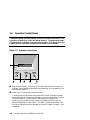
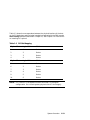
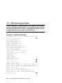
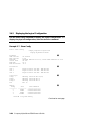
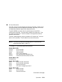
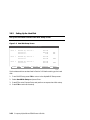
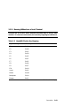
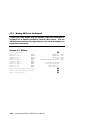
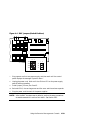
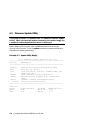
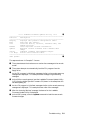
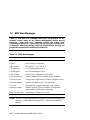
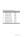
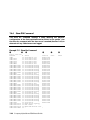
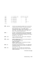
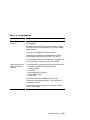
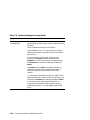
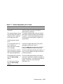
A few error messages that appear on the operator control panel are announced
by audible error beep codes, an indicated in Table 7–1. For example, a 1-1-4
beep code consists of one beep, a pause (indicated by the hyphen), one beep, a
pause, and a burst of four beeps. This beep code is accompanied by the message
“ROM err.”
Related messages are also displayed on the console terminal if the console
device is connected to the serial line and the SRM console environment
variable is set to serial.
Troubleshooting
7-3
7.1.2
Checksum Error
If Jump to Console is the last message displayed on the operator
control panel, the console firmware is corrupted. When the system
detects the error, it attempts to load a utility called the fail-safe loader
(FSL) so that you can load new console firmware images.
Example 7–1 Checksum Error and Fail-Safe Load
Loading console
Console ROM checksum error
Expect: 00000000.000000FE
Actual: 00000000.000000FF
XORval: 00000000.00000001
Loading program from floppy
Code execution complete (transfer control)
➊
➋
OpenVMS PALcode V1.3-3, Digital UNIX PALcode V1.4-2
starting console on CPU 0
.
.
starting drivers
entering idle loop
➌
P00>>> Boot update_cd
➍
OpenVMS PALcode V1.3-3, Digital UNIX PALcode V1.4-2
starting console on CPU 0
.
.
starting drivers
entering idle loop
.
.
.
7-4
Compaq AlphaServer ES40 User’s Guide
➎
➏
***** Loadable Firmware Update Utility *****
------------------------------------------------------------Function
Description
------------------------------------------------------------Display
Displays the system’s configuration table.
Exit
Done exit LFU (reset).
List
Lists the device, revision, firmware name, and
update revision.
Readme
Lists important release information.
Update
Replaces current firmware with loadable data
image.
Verify
Compares loadable and hardware images.
? or Help
Scrolls this function table.
-------------------------------------------------------------UPD> update
➐
The sequence shown in Example 7–1 occurs:
➊ The system detects the checksum error and writes a message to the console
screen.
➋ The system attempts to automatically load the FSL program from the
floppy drive.
➌ As the FSL program is initialized, messages similar to the console power-up
messages are displayed. This example shows the beginning and ending
messages.
➍ At the P00>>> console prompt, boot the Loadable Firmware Update Utility
(LFU) from the Alpha Systems Firmware CD (shown in the example as the
variable update_cd).
➎ As the LFU program is initialized, messages similar to the console power-up
messages are displayed. This example shows a few of the messages.
➏ After the “entering idle loop” message, the banner for the Loadable
Firmware Update Utility is displayed.
➐ At the UPD> prompt, enter the update command to load the new console
firmware images.
Troubleshooting
7-5
7.1.3
No MEM Error
If the SROM code cannot find any available memory, a 1-3-3 beep code
is issued (one beep, a pause, a burst of three beeps, a pause, and
another burst of three beeps), and the message “No MEM” is displayed.
The system does not come up to the console program. This error
indicates missing or bad DIMMs.
The console terminal displays text similar to the following:
Failed M:1 D:2
Failed M:1 D:1
Failed M:0 D:2
Failed M:0 D:1
Incmpat M:3 D:6
Incmpat M:3 D:5
Incmpat M:2 D:6
Incmpat M:2 D:5
Missing M:3 D:2
Incmpat M:3 D:1
Illegal M:2 D:2
Incmpat M:2 D:1
No usable memory detected
7-6
➊
➋
➌
➍
Compaq AlphaServer ES40 User’s Guide
➊ Indicates failed DIMMs. M identifies the MMB; D identifies the DIMM. In
this line, DIMM 2 on MMB1 failed.
➋ Indicates that some DIMMs in this array are not the same. All DIMMs in
the affected array are marked as incompatible (incmpat).
➌ Indicates that a DIMM in this array is missing. All missing DIMMs in the
affected array are marked as missing.
➍ Indicates that the DIMM data for this array is unreadable. All unreadable
DIMMs in the affected array are marked as illegal.
Troubleshooting
7-7
7.2
RMC Error Messages
Table 7–2 lists the error messages that might be displayed on the
operator control panel by the remote management console during
power-up.
Most fatal error messages prevent the system from
completing its power-up. Contact your service provider if a fatal error
is displayed. Warning messages require prompt attention but may not
prevent the system from completing its power-up.
Table 7–2 RMC Error Messages
Message
Meaning
Fatal Messages
AC loss
No AC power to the system.
CPUn failed
CPU failed. “n” is 0, 1, 2, or 3.
VTERM failed
No VTERM voltage to CPUs.
CTERM failed
No CTERM voltage to CPUs.
Fan5, 6 failed
Main fan (6) or redundant fan (5) failed.
OverTemp failure
System temperature has passed the high threshold.
No CPU in slot 0
Configuration requires that a CPU be installed in slot 0.
CPU door opened
System card cage cover off. Reinstall cover.
TIG error
Code essential to system operation is not running.
Mixed CPU types
Different types of CPU are installed. Configuration
requires that all CPUs be the same type.
Bad CPU ROM data
Invalid data in EEROM on the CPU.
NOTE: The CPUn failed message does not necessarily prevent the completion of
power-up. If the system finds a good CPU, it continues the power-up
process.
7-8
Compaq AlphaServer ES40 User’s Guide
Table 7–2 RMC Error Messages (Continued)
Message
Meaning
Warning Messages
PSn failed
Power supply failed. “n” is 0, 1, or 2.
OverTemp Warning
System temperature is near the high threshold.
Fann failed
Fan failed. “n” is 0 through 6.
PCI door opened
Cover to PCI card cage is off. Reinstall cover.
Fan door opened
Cover to main fan area (fans 5 and 6) is off. Reinstall
cover.
3.3V bulk warn
Power supply voltage over or under threshold.
5V bulk warn
Power supply voltage over or under threshold.
12V bulk warn
Power supply voltage over or under threshold.
–12V bulk warn
Power supply voltage over or under threshold.
VTERM warn
Voltage regulator over or under threshold.
CTERM warn
Voltage regulator over or under threshold.
CPUn VCORE warn
CPU core voltage over or under threshold. “n” is 0, 1,
2, or 3.
CPUn VIO warn
I/O voltage on CPU over or under threshold. “n” is 0,
1, 2, or 3.
Troubleshooting
7-9
7.3
SROM Error Messages
The SROM power-up identifies errors that may or may not prevent the
system from coming up to the console. It is possible that these errors
may prevent the system from successfully booting the operating
system. Errors encountered during SROM power-up are displayed on
the operator control panel (OCP). Some errors are also displayed on
the console terminal if the console output is set to serial.
Table 7–3 lists the SROM error messages. Contact your service provider.
Table 7–3 SROM Error Messages
Code
SROM Message
OCP Message
FD
FA
EF
EE
ED
EC
EB
EA
E9
E8
E7
E6
E5
E4
E3
E2
E1
E0
7F
PCI data path error
No usable memory detected
Bcache data lines test error
Bcache data march test error
Bcache address test error
CPU parity detection error
CPU ECC detection error
Bcache ECC data lines test error
Bcache ECC data march test error
Bcache TAG lines test error
Bcache TAG march test error
Console ROM checksum error
Floppy driver error
No real-time clock (TOY)
Memory data path error
Memory address line error
Memory pattern error
Memory pattern ECC error
Configuration error on CPU #3
PCI Err
No Mem
BC Error
BC Error
BC Error
CPU Err
CPU Err
BC Error
BC Error
BC Error
BC Error
ROM Err
Flpy Err
TOY Err
Mem Err
Mem Err
Mem Err
Mem Err
CfgERR 3
7-10
Compaq AlphaServer ES40 User’s Guide
Table 7–3 SROM Error Messages (Continued)
Code
SROM Message
OCP Message
7E
7D
7C
7B
7A
79
78
77
76
75
74
73
Configuration error on CPU #2
Configuration error on CPU #1
Configuration error on CPU #0
Bcache failed on CPU #3 error
Bcache failed on CPU #2 error
Bcache failed on CPU #1 error
Bcache failed on CPU #0 error
Memory thrash error on CPU #3
Memory thrash error on CPU #2
Memory thrash error on CPU #1
Memory thrash error on CPU #0
Starting secondary on CPU #3 error
CfgERR 2
CfgERR 1
CfgERR 0
BC Bad 3
BC Bad 2
BC Bad 1
BC Bad 0
MtrERR 3
MtrERR 2
MtrERR 1
MtrERR 0
RCPU 3 E
72
71
70
6F
Starting secondary on CPU #2 error
Starting secondary on CPU #1 error
Starting secondary on CPU #0 error
Configuration error with system
RCPU 2 E
RCPU 1 E
RCPU 0 E
CfgERR S
Troubleshooting
7-11
7.4
SRM Diagnostics
The SRM console event log and SRM console commands help you
troubleshoot problems that do not prevent the system from coming up
to the console.
7.4.1
Console Event Log
A console event log consists of status messages received during powerup self-tests. If problems occur during power-up, error messages
indicated by asterisks (***) may be embedded in the console event log.
To display a console event log one screen at a time, use the more el
command.
Example 7–2 shows a console event log that shows errors. The console reported
that CPU 1 did not power up and fans 1 and 2 failed.
Example 7–2 Sample Console Event Log
>>> more el
*** Error - CPU 1 failed powerup diagnostics ***
Secondary start error
EV6 BIST
= 1
STR status
= 1
CSC status
= 1
PChip0 status
= 1
PChip1 status
= 1
DIMx status
= 0
TIG Bus status
= 1
DPR status
= 0
CPU speed status = 0
CPU speed
= 0
Powerup time
= 00-00-00 00:00:00
CPU SROM sync
= 0
*** Error - Fan 1 failed ***
*** Error - Fan 2 failed ***
7-12
Compaq AlphaServer ES40 User’s Guide
7.4.2
Show Device Command
Use the SRM show device command to list the controllers and bootable
devices in the system. If storage devices are missing from the display,
see Table 7–7.
Example 7–3 Show Device Command
P00>>> show device
dka0.0.0.1.1
dka100.1.0.1.1
dka200.2.0.1.1
dkb0.0.0.3.1
dqa0.0.0.15.0
dva0.0.0.1000.0
ewa0.0.0.4.1
ewb0.0.0.2002.1
pka0.7.0.1.1
pkb0.7.0.3.1
pkc0.7.0.2000.1
pkd0.7.0.2001.1
DKA0
DKA100
DKA200
DKB0
DQA0
DVA0
EWA0
EWB0
PKA0
PKB0
PKC0
PKD0
RZ2DD-LS
RZ2DD-LS
RZ1CB-CS
RZ25
TOSHIBA CD-ROM XM-6302B
0306
0306
0844
0900
1012
00-00-F8-09-90-FF
00-06-2B-00-25-5B
SCSI Bus ID 7
SCSI Bus ID 7
SCSI Bus ID 7
SCSI Bus ID 7
Troubleshooting
7-13
7.4.3
Test Command
The test command verifies all the devices in the system. This command
can be used on all supported operating systems.
Example 7–4 Test Command
P00>>> test
Testing the Memory
Testing the DK* Disks(read only)
No DU* Disks available for testing
No DR* Disks available for testing
Testing the DQ* Disks(read only)
Testing the DF* Disks(read only)
No MK* Tapes available for testing
No MU* Tapes available for testing
Testing the DV* Floppy Disks(read only)
Testing the VGA (Alphanumeric Mode only)
Testing the EWA0 Network
Testing the EWB0 Network
P00>>>
The test command also does a quick test on the system speaker. A beep is
emitted as the command starts to run.
The tests are run sequentially, and the status of each subsystem test is
displayed to the console terminal as the tests progress. If a particular device is
not available to test, a message is displayed. The test script does no destructive
testing; that is, it does not write to disk drives.
The syntax is:
test [argument]
Use the -lb (loopback) argument for console loopback tests.
To run a complete diagnostic test using the test command, the system
configuration must include:
•
A serial loopback connected to the COM2 port (not included)
•
A parallel loopback connected to the parallel port (not included)
7-14
Compaq AlphaServer ES40 User’s Guide
•
A trial diskette with files installed
•
A trial CD-ROM with files installed
The test script tests devices in the following order:
1. Memory tests (one pass)
2.
Read-only tests: DK* disks, DR* disks, DQ* disks, DU* disks, MK* tapes,
DV* floppy.
3.
Console loopback tests if -lb argument is specified: COM2 serial port and
parallel port.
4.
VGA console tests: These tests are run only if the console environment
variable is set to serial. The VGA console test displays rows of the word
compaq.
5.
Network internal loopback tests for EW* networks.
NOTE: No write tests are performed on disk and tape drives. Media must be
installed to test the diskette drive and tape drives.
Testing a Windows NT System
To test a system running Windows NT, invoke the SRM console in one of the
following ways and then enter the test command.
•
From the AlphaBIOS console, press the Halt button, and press the Reset
button to reset the system.
•
Alternatively, select UNIX (SRM) or OpenVMS (SRM) from the Advanced
CMOS Setup screen and then reset the system.
The second method changes the os_type environment variable to unix or
openvms, causing the SRM console to start on each subsequent reset. To
restore your original setup for Windows NT, enter the following commands
while still in the SRM console:
P00>>> set os_type nt
P00>>> init
Troubleshooting
7-15
7.4.4
Show FRU Command
The show fru command displays a table showing the physical
configuration of the field-replaceable units (FRUs) in the system. Use
the show fru command with the show error command (Section 7.4.5) to
determine if any FRUs have errors logged.
Example 7–5 Show Fru Command
➊
➋
P00>>> show fru
FRUname
SMB0
SMB0.CPU0
SMB0.CPU1
SMB0.CPU2
SMB0.CPU3
SMB0.MMB0
SMB0.MMB0.DIM1
SMB0.MMB0.DIM2
SMB0.MMB0.DIM3
SMB0.MMB0.DIM4
SMB0.MMB0.DIM5
SMB0.MMB0.DIM6
SMB0.MMB1
SMB0.MMB1.DIM1
SMB0.MMB1.DIM2
SMB0.MMB1.DIM3
SMB0.MMB1.DIM4
SMB0.MMB1.DIM5
SMB0.MMB1.DIM6
SMB0.MMB2
SMB0.MMB2.DIM1
SMB0.MMB2.DIM2
SMB0.MMB2.DIM3
SMB0.MMB2.DIM4
SMB0.MMB2.DIM5
SMB0.MMB2.DIM6
SMB0.MMB3
SMB0.MMB3.DIM1
SMB0.MMB3.DIM2
SMB0.MMB3.DIM3
SMB0.MMB3.DIM4
SMB0.MMB3.DIM5
SMB0.MMB3.DIM6
SMB0.CPB0
SMB0.CPB0.PCI4
SMB0.CPB0.PCI5
SMB0.CPB0.PCIA
SMB0.CPB0.SBM0
7-16
E
00
00
00
00
00
00
00
00
00
00
00
00
00
00
00
00
00
00
00
00
00
00
00
00
00
00
00
00
00
00
00
00
00
00
00
00
00
00
➌
Part#
54-25385-01.C03
54-30158-03.A05
54-30158-03.A05
54-30158-03.A05
54-30158-03.A05
54-25582-01.B02
54-24941-EA.A01CPQ
54-24941-EA.A01CPQ
54-24941-EA.A01CPQ
54-24941-EA.A01CPQ
54-24941-EA.A01CPQ
54-24941-EA.A01CPQ
54-25582-01.B02
54-25053-BA.A01CPQ
54-25053-BA.A01CPQ
54-25053-BA.A01CPQ
54-25053-BA.A01CPQ
54-25053-BA.A01CPQ
54-25053-BA.A01CPQ
54-25582-01.B02
54-25053-BA.A01CPQ
54-25053-BA.A01CPQ
54-25053-BA.A01CPQ
54-25053-BA.A01CPQ
54-25053-BA.A01CPQ
54-25053-BA.A01CPQ
54-25582-01.B02
54-25053-BA.A01CPQ
54-25053-BA.A01CPQ
54-25053-BA.A01CPQ
54-25053-BA.A01CPQ
54-25053-BA.A01CPQ
54-25053-BA.A01CPQ
54-30156-01
ELSA GLoria Synergy
NCR 53C895
DE500-BA Network Cont
-
➍
➎
Serial#
Misc.
NI81561341
NI90260078
NI90260073
NI90260056
NI90260071
AY90112345
NI90202001
NI90200102
NI90200103
NI90200104
NI90202005
NI90202006
AY90112301
NI90112341
NI90112342
NI90112343
NI90112344
NI90112345
AY80112346
AY80012302
NI90112331
AY80112332
AY80112333
AY80112334
AY80112335
AY80112336
AY90112303
AY80112341
AY80112342
AY80112343
AY80112344
AY80112345
AY80112346
AY80100999
-
Compaq AlphaServer ES40 User’s Guide
➏
Other
PWR0
PWR1
FAN1
FAN2
FAN3
FAN4
FAN5
FAN6
JIO0
OCP0
00
00
00
00
00
00
00
00
00
00
30-49448-01.A02
30-49448-01.A02
70-40073-01
70-40073-01
70-40072-01
70-40071-01
70-40073-02
70-40074-01
54-25575-01
70-33894-0x
2P90700557 API-7850
2P90700558 API-7850
Fan
Fan
Fan
Fan
Fan
Fan
Junk I/O
OCP
P00>>>
➊
FRUname
The FRU name recognized by the SRM console. The name also
indicates the location of that FRU in the physical hierarchy.
SMB = system board; CPU = CPUs; MMB = memory
motherboard; DIM = DIMMs; CPB = PCI backplane; PCI = PCI
option; SBM = SCSI backplane; PWR = power supply; FAN =
fans; JIO= I/O connector module (junk I/O).
➋
E
Error field. Indicates whether the FRU has any errors logged
against it. FRUs without errors show 00 (hex). FRUs with
errors have a non-zero value that represents a bit mask of
possible errors. See Table 7–4.
➌
Part #
The part number of the FRU in ASCII, either a Compaq part
number or a vendor part number.
➍
Serial #
The serial number. For Compaq FRUs, the serial number has
the form XXYWWNNNNN.
XX = manufacturing location code
YWW = year and week
NNNNN = sequence number. For vendor FRUs, the 4-byte
sequence number is displayed in hex.
➎
Misc.
Miscellaneous information about the FRUs. For Compaq FRUs,
a model name, number, or an “a.k.a” name. For vendor FRUs,
the manufacturer’s name.
➏
Other
Optional data. For Compaq FRUs, the Compaq part alias
number (if one exists). For vendor FRUs, the year and week
number of manufacture.
Continued on next page
Troubleshooting
7-17
Table 7–4 Bit Assignments for Error Field
Bit
Meaning
Bit 0 is 1
Failure
Bit 1 is 1
TDD error has been logged
Bit 2 is 1
At least one SDD error has been logged
Bit 3 is 1
FRU EEPROM is unreadable
Bit 4 is 1
Checksum failure on bytes 0-62
Bit 5 is 1
Checksum failure on bytes 64-126
Bit 6 is 1
Checksum failure on bytes 128-254
Bit 7 is 1
FRU’s system serial does not match system’s
NOTE: Contact your service provider if the E (error) field shows any of these
errors.
7-18
Compaq AlphaServer ES40 User’s Guide
7.4.5
Show Error Command
The show error command displays FRUs that have errors logged. If the
devices installed do not have any errors in their EEPROM, a show
error command redisplays the SRM console prompt. Example 7–6
shows errors logged in the system board's EEPROM. Contact your
service provider if the show error command displays an error.
Example 7–6 Show Error Command
P00>>> show error
SMB0
TDD - Type: 1 Test: 1 SubTest: 1 Error: 1
SMB0
SDD - Type: 4 LastLog: 1 Overwrite: 0
P00>>>
Troubleshooting
7-19
7.4.6
Show Power Command
Use the SRM show power command to determine whether the failure of
a system running UNIX or OpenVMS was related to a fan, temperature,
or power supply problem. You can use this command if you are able to
restart the system. Otherwise, invoke RMC and use the env command.
Example 7–7 Show Power Command
P00>>> show power
Power Supply 0
Power Supply 1
Power Supply 2
System Fan 1
System Fan 2
System Fan 3
System Fan 4
System Fan 5
System Fan 6
CPU 0 Temperature
CPU 1 Temperature
CPU 2 Temperature
CPU 3 Temperature
Zone 0 Temperature
Zone 1 Temperature
Zone 2 Temperature
P00>>>
7-20
Status
Good
Good
Not Available
Good
Good
Bad
Good
Good
Good
Warning
Good
Good
Good
Good
Good
Good
Compaq AlphaServer ES40 User’s Guide
➊
➋
➌
➍
➊
➋
➌
➍
Power supplies. Power supply 2 is not installed.
System fans. Fan 3 is not working.
Temperature sensors on CPUs. CPU 0 is above threshold.
Temperature sensors on PCI backplane.
Troubleshooting
7-21
7.4.7
Crash Command
For fatal errors, the UNIX and OpenVMS operating systems will save
the contents of memory to a crash dump file. Crash dump files can be
used to determine why the system crashed.
Example 7–8 Crash Command
P00>>> crash
CPU 0 restarting
DUMP: 19837638 blocks available for dumping.
DUMP: 118178 wanted for a partial compressed dump.
DUMP: Allowing 2060017 of the 2064113 available on 0x800001
device string for dump = SCSI 1 1 0 0 0 0 0.
DUMP.prom: dev SCSI 1 1 0 0 0 0 0, block 2178787
DUMP: Header to 0x800001 at 2064113 (0x1f7ef1)
device string for dump = SCSI 1 1 0 0 0 0 0.
DUMP.prom: dev SCSI 1 1 0 0 0 0 0, block 2178787
DUMP: Dump to 0x800001: .......: End 0x800001
device string for dump = SCSI 1 1 0 0 0 0 0.
DUMP.prom: dev SCSI 1 1 0 0 0 0 0, block 2178787
DUMP: Header to 0x800001 at 2064113 (0x1f7ef1)
succeeded
halted CPU 0
halt code = 5
HALT instruction executed
PC = fffffc0000568704
P00>>>
7-22
Compaq AlphaServer ES40 User’s Guide
The SRM crash command forces a crash dump to the selected device for UNIX
and OpenVMS systems. Use this command when the system has hung and you
are able to halt it with the Halt button or the RMC halt in command. The
crash command restarts the operating system and forces a crash dump to the
selected device.
Troubleshooting
7-23
7.5
Troubleshooting Tables
This section describes some strategies for troubleshooting problems
that might prevent the system from completing its power-up or that
might prevent you from booting the operating system.
Use the
troubleshooting tables on the following pages to diagnose the following
types of problems.
•
Power problems
•
Problems that prevent the system from powering up to the SRM console
prompt
•
Failures reported on the SRM console
•
Boot problems
•
Errors reported by the operating system
NOTE: Check your service agreement before handling internal parts of the
system. If in doubt, contact your service provider.
7-24
Compaq AlphaServer ES40 User’s Guide
Table 7–5 Power Problems
Symptom
Action
System does not
power on.
Check that AC power is available and all power cords
are plugged in.
Check the Power setting on the control panel. Toggle
the Power button to off, then back on to clear a remote
power disable.
Check error messages on the control panel.
Check that the ambient room temperature is within
environmental specifications (10–40°C, 50–104°F).
Internal power supply cables might not be plugged in at
the system board. Contact your service provider.
Power supply shuts
down after a few
seconds
The system may be powered off by one of the following:
—A remote management console command
—System software
—Fan failure
—Over-temperature condition
—Power supply failure
—Faulty CPU
Invoke RMC and use the env command for an
indication of a hardware problem. See Chapter 4 for
information on RMC.
Check that the power supplies are installed correctly
and correctly seated.
Troubleshooting
7-25
Table 7–6 Problems Getting to Console Mode
Symptom
Action
Power-up screen is
not displayed.
Interpret the error beep codes and observe the control
panel display at power-up for a failure detected during
self-tests.
Check keyboard and monitor connections.
Press the Return key. If the system enters console
mode, check that the console environment variable is
set correctly.
If you are using a VGA monitor as the console
terminal, the console variable should be set to
graphics. If you are using a serial console terminal,
the console environment variable should be set to
serial.
If console is set to serial, the power-up display is
routed to the COM1 serial communication port or
MMJ port and cannot be viewed from the VGA
monitor.
Try connecting a console terminal to the COM1 serial
communication port. When using the COM1 port, you
must set the console environment variable to serial.
If the system has a customized NVRAM file, try
pressing the Halt button and then powering up or
resetting the system. This will bypass the NVRAM
script.
7-26
Compaq AlphaServer ES40 User’s Guide
Table 7–7 Problems Reported by the Console
Symptom
Action
Power-up tests are not
completed.
Interpret the error beep codes at power-up and
check the power-up screen for a failure
detected during self-tests.
The system attempts to boot
from the floppy drive after a
checksum error is reported
(error beep code 1-1-4).
The system automatically reverts to the failsafe loader to load new SRM and AlphaBIOS
firmware. If the fail-safe load does not work,
contact your service provider to replace the
system board.
Console program reports
error:
Error beep codes report an
error at power-up.
Use the error beep codes and control panel
messages to determine the error.
Power-up screen includes
error messages.
Enter the more el command when the SRM
prompt is displayed to read the event log.
Power-up screen or console
event log indicates problems
with mass storage devices.
Check the cabling and seating of the device. If
this is not the problem, the device is bad and
should be replaced.
Storage devices are missing
from the show config
display.
Check the cabling and seating of the device,
then wait 5 seconds for the device to appear in
the console display. If the device still does not
appear, contact your service provider.
PCI devices are missing
from the show config
display.
See Section 7.6.
Troubleshooting
7-27
Table 7–8 Boot Problems
Symptom
Action
System cannot find
boot device.
Check the system configuration for the correct device
parameters (node ID, device name, and so on).
For UNIX and OpenVMS, use the show config and
show device commands.
For Windows NT, use the AlphaBIOS Display
System Configuration menu and the CMOS Setup
menus.
Check the system configuration for the correct
environment variable settings.
For UNIX and OpenVMS, examine the auto_action,
bootdef_dev, boot_osflags, and os_type
environment variables.
For network boots, make sure ei*0_protocols or
ew*0_protocols is set to bootp for UNIX or mop
for OpenVMS.
For Windows NT, examine the Auto Start and Auto
Start Count options on the CMOS Setup menu.
Device does not boot.
For problems booting over a network, make sure
ei*0_protocols or ew*0_protocols is set to bootp
for UNIX or mop for OpenVMS.
Run the test command to check that the boot device
is operating.
7-28
Compaq AlphaServer ES40 User’s Guide
Table 7–9 Errors Reported by the Operating System
Symptom
Action
System has crashed, but
SRM console is operating.
Press the Halt button and enter the SRM crash
command to provide a crash dump file for
analysis. (OpenVMS and UNIX only.)
If the problem is intermittent, run the SRM test
command.
Refer to the OpenVMS Alpha System Dump
Analyzer Utility Manual for information on how
to interpret OpenVMS crash dump files.
Refer to the Guide to Kernel Debugging for
information on using the UNIX Krash Utility.
System is hung and SRM
console is not operating.
Contact your service provider.
Operating system has
crashed and rebooted.
Contact your service provider. If the problem is
intermittent, you might have a defective
component.
Troubleshooting
7-29
7.6
Option Card Problems
Option card problems can include problems related to network options
and PCI options.
Network Problems
Network problems can vary, depending on the type of network option card that
you have installed. See the option card documentation for information on
troubleshooting network problems. Make sure you have correctly set the
network type for the network interface card.
PCI Parity Errors
Some PCI devices do not implement PCI parity, and some have a paritygenerating scheme that may not comply with the PCI Specification. In such
cases, the device functions properly as long as parity is not checked.
You can turn off parity checking so that false PCI parity errors do not result in
machine check errors. When you disable PCI parity, no parity checking is
implemented for any PCI device.
•
For UNIX and OpenVMS systems, use the set pci_parity off command
from the SRM console.
•
For Windows NT, set the PCI Parity Checking option on the Advanced
CMOS Setup menu to Disabled.
7-30
Compaq AlphaServer ES40 User’s Guide
PCI Bus Problems
PCI bus problems at startup are usually indicated by the inability of the system
to detect the PCI device. Use Table 7–10 to diagnose the likely cause of the
problem.
Table 7–10 Troubleshooting PCI Bus Problems
Step
Action
1
Check the cabling and confirm that the PCI card is correctly seated.
2
Run system console PCI diagnostics for devices on the Supported
Options List. (If the device is not on the list, refer to the device’s
documentation.)
•
Storage adapter—Run the test command to exercise the storage
devices off the PCI controller option.
•
Ethernet adapter—Run the test command to exercise an
Ethernet adapter.
3
Check for a bad slot by moving the suspected controller to a different
slot.
4
Contact the option manufacturer.
Troubleshooting
7-31
7.7
Troubleshooting the Windows NT Hard Disk
Table 7–11 gives AlphaBIOS error messages that indicate hard disk
problems and suggests possible causes and solutions.
Table 7–11 Troubleshooting the System Hard Disk
Error Message
Possible Cause
Corrective Action
“Internal error
occurred”
Incompatible or failed
disk cables.
Try another cable known to
be good.
Disk controller not
configured.
Check your hard disk
controller documentation to
see if you have to run a
configuration utility to set
up your hard disk.
Disk controller
malfunction.
Test controller functioning
using the controller’s
diagnostic utility. If an
error is found, contact your
service representative for a
replacement.
Improper SCSI
termination.
Check to see that
terminating resistor packs
are removed from all drives
except the controller itself
and the last drive
connected to it.
7-32
Compaq AlphaServer ES40 User’s Guide
Table 7–11 Troubleshooting the System Hard Disk (Continued)
Error Message
Possible Cause
Corrective Action
“No hard drives
were found
connected to your
computer”
No hard disk installed.
Install hard disk.
Cable not connected to
either the disk or
controller.
Check the cable connections to
ensure that cable connectors
are fully seated.
Cable not connected to
either the disk or
controller.
Check the cable connections to
ensure that cable connectors
are fully seated.
No power to drive.
Check cable connections. If
problem persists, try
connecting the drive to a
different power connector.
Disk drive
malfunction.
Try replacing the drive with a
drive known to be good. If
problem persists, hard drive
is defective. Contact your
service provider.
Hard disk 0 does not
have any partitions
defined.
Perform an express disk setup
to automatically create
default disk partition
arrangement on hard disk 0.
“Perform an
express disk
setup?”
Troubleshooting
7-33
Chapter 8
Specifications
This chapter gives specifications for Compaq AlphaServer ES40 systems:
•
Physical specifications
•
Environmental specifications
•
Electrical specifications
•
Regulatory approvals
•
Acoustical data
Specifications
8-1
8.1
Physical Specifications
Table 8–1 Physical Characteristics — Tower
Dimensions
Height
Width
Depth
Weight
50.8 cm (20.0 in.)
38.7 cm (15.25 in.)
78.7 cm (31.0 in.)
Nominal: 65 kg (143 lb)
Max: 96 kg (211 lb)
Shipping Container
Height
Width
Depth
Weight
82.4 cm (32.2 in.)
60.2 cm (24.0 in.)
101.6 cm (40.0 in.)
Nominal: 78 kg (172 lb)
Max: 110 kg (242 lb)
Clearances
Front
Rear
Left side
Right side
8-2
Operating
Service
75 cm (29.5 in.)
15 cm (6 in.)
None
None
75 cm (29.5 in.)
75 cm (29.5 in.)
75 cm (29.5 in.)
None
Compaq AlphaServer ES40 User’s Guide
Table 8–2 Physical Characteristics — Pedestal
Dimensions
Height
Width
Depth
Weight
78.2 cm (30.8 in.)
50.8 cm (20.0 in.)
80.6 cm (31.75 in.)
Nominal: 127 kg (280 lb)
Max: 159 kg (350 lb)
Shipping Container
Height
Width
Depth
Weight
107.7 cm (42.4 in.)
100.3 cm (39.5 in.)
60.7 cm (23.9 in.)
Nominal: 149 kg (328 lb)
Max: 185 kg (407 lb)
Clearances
Front
Rear
Left side
Right side
Operating
Service
75 cm (29.5 in.)
15 cm (6 in.)
None
None
75 cm (29.5 in.)
75 cm (29.5 in.)
None
75 cm (29.5 in.)
Specifications
8-3
Table 8–3 Physical Characteristics — Rackmount
Dimensions
Height
35.2 cm (13.87 in.)
Width
44.7 cm (17.6 in.)
Depth
Weight
1. When lifting
2. Total added to
cabinet (includes
brackets, slides, and
cables)
76.5 cm (30.1 in.)
Nominal: 50 kg (110 lb)
Nominal: 59 kg (130 lb)
Fits 14 in. [8U]
standard RETMA
cabinets
Max: 76 kg (167.2 lb)
Max: 92 kg (202.4 lb)
Shipping Container
Height
Width
Depth
Weight
73.2 cm (28.8 in.)
60.7 cm (24.0 in.)
101.6 cm (40.0 in.)
Nominal: 72 kg (158 lb)
Max: 106 kg (233 lb)
Clearances
8-4
Operating
Service
See requirements of specific
cabinet.
Min: 121.9 cm (4 ft)
76.3 cm (30 in.)
withdrawal on rails)
Compaq AlphaServer ES40 User’s Guide
Table 8–4 Physical Characteristics — Cabinets
Dimensions
H9A10 M-Series
Height
Width
Depth
Weight
170 cm (67.0 in.)
60 cm (23.6 in.)
110 cm (43.27 in.)
Configuration-dependent
Max payload 1000 lb
H9A15 M-Series
Height
Width
Depth
Weight
200 cm (79.0 in.)
60 cm (23.6 in.)
110 cm (43.27 in.)
Configuration-dependent
Max payload 1000 lb
Shipping Container
H9A10 M-Series
Height
Width
Depth
Weight
185.5 cm (73 in.)
91.5 cm (36 in.)
122 cm (48 in.)
Nominal: 430 kg (946 lb)
Max: 625 kg (1375 lb)
H9A15 M-Series
Height
Width
Depth
Weight
216 cm (85 in.)
91.5 cm (36 in.)
122 cm (48 in.)
Nominal: 550 kg (1056 lb)
Max: 640 kg (1408 lb)
Specifications
8-5
8.2
Environmental Specifications
Table 8–5 Environmental Characteristics — All System Variants
Temperature
Operating
Nonoperating
Storage (60 days)
Rate of change
10–35o C (50–95o F)
Not tested
–40 to 66o C (–40 to 151o F)
o
o
11 C/hr (20 F/hr)
Relative humidity
Operating
Nonoperating
Storage (60 days)
Rate of change
20 to 80%
20 to 80%
10 to 95%
20%/hr
Max wet bulb temp
Operating
Storage (60 days)
28o C (82o F)
o
o
46 C (115 F)
Min dew point temp
Operating
Storage (60 days)
2o C (360 F)
Not tested
Heat dissipation
Nominal
Maximum
Tower and Rack
Pedestal
H9A10/H9A15
900 w, 3074 BTU/hr
1480 w, 5054 BTU/hr
Config-dependent
1300 w, 4440 BTU/hr
2400 w, 8196 BTU/hr
4800 w, 16392 BTU/hr
Airflow and quality
Intake location
Exhaust location
Particle size
Concentration
Front
Tower, Pedestal, and
Rackmount: Rear
H9A10/H9A15: Rear and top
N/A
N/A
Altitude
Operating
Nonoperating
3037 m (10,000 ft)
12190 m (40,000 ft)
Mechanical shock
Operating
Tower/Pedestal
M-Series Cabinet
7.5 G, 10 +/– 3 ms
5.0 G, 10 +/– 3 ms
Operating
10–500 Hz .1 G peak
Vibration
8-6
Compaq AlphaServer ES40 User’s Guide
8.3
Electrical Specifications
Table 8–6 Electrical Characteristics — All System Variants
Nominal voltage (Vac)
Voltage range (Vac)
temporary condition)
Power source phase
Nominal frequency (Hz)
Frequency range (Hz)
RMS current (max. steady state)
Tower and Rackmount
Single power cord
Multiple power cords
Pedestal
Each power cord
M-Series cab config.-dependent
Nominal voltage (Vac)
Each power cord
System Variant
100
90–110
120
110–128
200–240
180–250
Single
50/60
49–51/59–61
Single
50/60
49–51/59–61
Single
50/60
49–51/59–61
11.0 A
6.5 A
8.5 A
5.3 A
5.0 A
3.0 A
12.0 A
10.5 A
7.0 A
100
24 A
120
24 A
220–240
16 A
Power Cords
Quantity
Length
Type
Tower
Up to 3
190 cm (75 in.)
IEC 320 C13 to NEMA 5–15
(N. America) or
IEC 320 C13 to country-specific
Pedestal
2
190 cm (75 in.)
120 V nonremovable NEMA 5–15
(N. America) or
200–240 V IEC 320 C13 to
country- specific
Rackmount
3
452 cm
(14 ft. 10 in.)
IEC 320 C13 to NEMA 5–15
(N. America) or
IEC 320 C13 to IEC 320 C14
(other countries)
Cabinet
2
330 cm
120 V nonremovable NEMA
L5-30P or
200–240 V nonremovable
IEC 309
(10 ft 10 in.)
NOTE:
Power supplies are universal, PFC, auto ranging, 100/120/200–240 Vac.
Specifications
8-7
8.4
Regulatory Approvals
Table 8–7 Regulatory Approvals
Agency approvals
Reviewed to
8-8
rd
UL: Listed to UL1950 (3 edition) and to
CAN/CSA-C22.2 No. 950-M95
TUV: EN 60950/A4:1997 GS marked
FCC: Part 15.B Class A
CE: EN55022, en50082
VCCI Class II ITE
BCIQ: CISPR22, CNS13438
c-Tick: CISPR22, as/nzs 3548
AS/NZ 3260:1993 Australian/New Zealand
Standard
EN 60950/A4: 1997 European Norm
IEC 950 (2nd edition, 3rd amend)
Compaq AlphaServer ES40 User’s Guide
8.5
Acoustical Data
Table 8–8 gives the noise declaration for the AlphaServer ES40 system.
Table 8–8 Acoustical Data
Acoustics — Declared Values per ISO 9296 and ISO 7779
LWAd, B
LpAm, dBA
(bystander positions)
Product
Idle
Operate
Idle
Operate
DH–64AAA-AA (AlphaServer ES40)
[with 0 x HDD]
DH–64AAA–AA + DS–RZ2ED–16
6.6
6.6
48
48
6.6
6.6
48
48
DH–64AAA–AA + DS-RZ2ED–16 +
BA36R–R* + 6 x DS-RZ1ED–VW
6.7
6.8
49
50
Current values for specific configurations are available from Compaq representatives.
1 B = 10 dBA.
Specifications
8-9
Index
A
Acoustics, 8-9
AlphaBIOS console
boot screen, 2-11, 2-13, 3-20
CMOS Setup screen, 2-31
Display System Configuration screen, 2-30
hard disk setup, 2-33
memory test, 2-34
running in serial mode, 2-44
setting date and time, 2-32
setup screen, 2-12
startup screens, 2-10
AlphaBIOS initialization screen, 2-10
AlphaBIOS utilities, 2-40
APB program, 3-17
Auto start, 2-36
UNIX or OpenVMS, 2-38
Windows NT, 2-37
auto_action environment variable, 2-38
Autoboot, 2-36
Auxiliary power supply, RMC, 4-3
B
Boot device, setting, 2-39
Boot flags
OpenVMS, 3-5
UNIX, 3-4
Boot options, 3-2
Boot problems, 7-28
Boot procedure
OpenVMS, 3-15
UNIX, 3-9
Windows NT, 3-21
Boot screen, AlphaBIOS, 2-13, 3-20
boot_file environment variable, 3-3
boot_osflags environment variable, 3-4
bootdef_dev environment variable, 3-2
Booting
OpenVMS, 3-14
OpenVMS, from InfoServer, 3-16
OpenVMS, from local CD-ROM, 3-14
UNIX, from SCSI disk, 3-8
UNIX, from the network, 3-10
Windows NT, 3-20
bootp protocol, 3-7
Bypass modes, 4-6
Bypassing the RMC, 4-6
C
Checksum error, 7-4
CMOS Setup screen, 2-31
COM1 data flow, defining, 4-15
COM1 environment variables, 4-12
com1_mode environment variable, 4-4
Command conventions, RMC, 4-14
Components
system chassis, 1-3
system front, 1-4
system rear, 1-5
Configuration
CPU, 5-19
memory, 5-23
PCI, 5-30
power supply, 5-11
Connectors, rear, 1-6
console environment variable (SRM), 2-3, 215
Console event log, 7-12
Console programs, 2-12
Index-1
Console tests, 7-15
Console, selecting, 2-15
Consoles, switching between, 2-14
Control panel, 1-8
Control panel messages, 2-3
Controls
halt button, 1-9
power button, 1-8
reset button, 1-9
Covers
removing from pedestal or rack, 5-8
removing from tower, 5-7
CPU card, 1-11
CPU slot locations, 5-18
CPUs
configuring, 5-19
installing, 5-20
crash command (SRM), 7-22
Crash dump, 7-23
D
Date and time, setting in AlphaBIOS, 2-32
Device naming, SRM, 2-26
Diagnostic tests, 7-14
Diagnostics, 7-2
Dial-in configuration, 4-22
Dial-out alert, 4-24
DIMMs
configuring, 5-23
installing, 5-26
Disk cage, installing, 5-38
Display device, selecting, 2-15
Display device, verifying, 2-16
Display System Configuration screen, 2-30
DPR, 4-3
Dual-port RAM, 4-3
E
EEPROMs, 4-3
ei*0_inet_init environment variable, 3-6
ei*0_protocols environment variable, 3-7
Electrical specifications, 8-7
Enclosure panels
removing, 5-2
removing from a pedestal, 5-5
removing from a tower, 5-3
Index-2
env command (RMC), 4-18
Environment, monitoring, 4-18
Environmental specifications, 8-6
Error beep codes, 7-2
Error log information, RMC, 4-3
Error messages
from RMC, 7-8
SROM, 7-11
Errors reported by operating system, 7-29
Escape sequence (RMC), 4-10
Event log, 7-12
ew*0_inet_init environment variable, 3-6
ew*0_protocols environment variable, 3-7
F
Factory-installed software (FIS), 3-1
Fail-safe loader, 7-4
Fan failure, 7-25
Firm bypass mode, 4-8
Firmware
updating, 6-1
updating from AlphaBIOS, 6-8
updating from OpenVMS system disk, 6-9
updating from SRM, 6-7
updating using BOOTP, 6-10
updating using MOP, 6-11
Firmware update utility, 6-4
Firmware updates
AlphaBIOS Web location, 6-2
Internet access, 6-2
manual, 6-6
quarterly update service, 6-2
sources of, 6-2
Flash ROM, updating, 6-6
Flash SROM, 2-5
FRUs, displaying, 7-16, 7-19
H
Halt button, 1-9
Halt in/out command (RMC), 1-9
Halt, remote, 1-9, 4-21
hangup command (RMC), 4-23
Hard disk setup, AlphaBIOS, 2-33
Hard disk troubleshooting, 7-32
Hard drives, 1-17
installing, 5-15
Hardware configuration
viewing, 2-18
Windows NT, 2-30
Hot-plug components, 5-9
I
InfoServer, 3-17
Initialization screen, AlphaBIOS, 2-10
Installing a disk cage, 5-38
Installing CPUs, 5-20
Installing DIMMs, 5-26
Installing hard drives, 5-14, 5-15
Installing OpenVMS, 3-18, 3-19
Installing PCI cards, 5-32
Installing power supplies, 5-12
Installing UNIX, 3-12
Installing Windows NT, 3-22, 3-23
ISL boot program, 3-17
K
Key mapping, AlphaBIOS, 2-44
L
LEDs
control panel, 1-8
power supply, 1-15
LFU, 6-4, 7-5
Local mode, 4-5
Loopback tests, 7-15
M
Memory configuration, 5-23
pedestal/rack, 5-24
tower, 5-25
Memory failure, 2-5
Memory test
settings in AlphaBIOS, 2-34
Messages, power-up, 2-3
Modules, system board, 1-10
MOP protocol, 3-7
more el command (SRM), 7-12
N
Network problems, 7-30
No MEM error, 7-6
O
OCP messages, 2-3
OpenVMS
booting, 3-14
booting from InfoServer, 3-17
booting from InfoServer, 3-16
booting from local CD-ROM, 3-14
installing, 3-18, 3-19
Operating systems
switching to UNIX or OpenVMS, 3-26
switching to Windows NT, 3-25
Operating systems, switching between, 3-24
Operator control panel, 1-8
customized message, 2-17
start-up messages, 2-3
Option card problems, 7-30
OSLOADER program, 2-39
P
Pagers, 4-26
Password protection, Windows NT, 2-35
PCI bus problems, 7-31
PCI cards, installing, 5-32
PCI parity errors, 7-30
PCI slot locations
pedestal, 5-30
tower, 5-31
PCI slots, 2-25
PCI, configuring, 5-30
Physical specifications, 8-2
PIC processor, 4-3
Ports, system rear, 1-7
Power button, 1-8
Power off/on command (RMC), 1-9
Power problems, 7-25
Power supplies, 1-14
configuring, 5-11
installation order, 5-11
installing, 5-12
locations, 5-10
Index-3
redundant, 5-11
Power supply LEDs, 1-15
Powering up, 2-2
Power-on, remote, 1-9
Power-on/off, from RMC, 4-20
Power-up display
SRM, 2-6
SROM, 2-4, 2-5
Power-up displays, 2-3
Power-up memory failure, 2-5
Power-up memory test, AlphaBIOS, 2-34
Power-up procedure, 2-5
Preboot tasks, Windows NT, 3-21
Problems getting to console mode, 7-26
Problems reported by console, 7-27
Processor card, 1-11
Q
quit command (RMC), 4-10
R
Redundant power supply, 5-11
Regulatory approvals, 8-8
Remote power-on/off, 4-20
Removable media, 1-16
Removable media device, installing, 5-36
Removing enclosure panels, 5-2
from a pedestal, 5-5
from a tower, 5-3
Reset button, 1-9
Reset command (RMC), 1-9
Reset, from RMC, 1-9, 4-21
RIS boot, 3-10
RIS boot procedure, 3-11
RMC
auxiliary power supply, 4-3
bypass modes, 4-6
CLI, 4-13
command conventions, 4-14
commands, 4-13
configuring call-out, 4-22
data flow diagram, 4-4
dial-out alert, 4-24
entering, 4-10
env command, 4-18
error messages, 7-8
Index-4
escape sequence, 4-10
exiting, 4-10
exiting from local VGA, 4-11
firm bypass mode, 4-8
hangup command, 4-23
local mode, 4-5
logic, 4-3
operating modes, 4-4
overview, 4-2
PIC processor, 4-3
quit command, 4-10
remote power on/off, 4-20
remote reset, 4-21
resetting to factory defaults, 4-29
set com1_mode command, 4-15
set escape command, 4-28
snoop mode, 4-7
soft bypass mode, 4-7
status command, 4-16
terminal setup, 4-9
through mode, 4-5
troubleshooting, 4-31
RMC firmware, updating, 6-6
S
SCSI bus length, 5-41
SCSI expansion, 5-41
Security, for SRM console, 2-29
Serial mode, setting up, 2-43
Serial terminal
running utilities from, 2-44
set com1_mode command (RMC), 4-15
set escape command (RMC), 4-28
set ocp_text command (SRM), 2-17
Setting SRM environment variables, 2-28
Setup, Windows NT, 2-31
Shared RAM, 4-3
show boot* command (SRM), 2-19
show command (SRM), 2-18
show config command (SRM), 2-20
show device command (SRM), 2-26
show error command (SRM), 7-19
show fru command (SRM), 7-16
show memory command (SRM), 2-27
show power command (SRM), 7-20
Slot numbers
CPUs, 5-18
PCI, 5-30, 5-31
Snoop mode, 4-7
Soft bypass mode, 4-7
Specifications, 8-2
SRM console, 2-13
device naming, 2-26
power-up display, 2-6
security, 2-29
SRM console commands
crash, 7-22
show boot*, 2-19
show config, 2-20
show device, 2-26
show error, 7-19
show fru, 7-16
show memory, 2-27
show power, 7-20
test, 7-14
SRM diagnostics, 7-12
SRM environment variables, setting, 2-28
SROM
error messages, 7-11
power-up display, 2-4, 2-5
power-up messages, 2-3
Startup screens, AlphaBIOS, 2-10
status command (RMC), 4-16
Storage
hard drive, 1-17
removable media, 1-16
System board, 1-10
System chassis
components, 1-3
System diagnostics, 7-2
System enclosures, 1-2
T
Terminal setup (RMC), 4-9
test command (SRM), 7-14
Through mode (RMC), 4-5
Tools for installation, 5-1
Troubleshooting
boot problems, 7-28
categories of problems, 7-24
errors reported by operating system, 7-29
network problems, 7-30
option card problems, 7-30
PCI bus problems, 7-31
PCI parity errors, 7-30
power problems, 7-25
problems getting to console mode, 7-26
problems reported by console, 7-27
RMC, 4-31
system diagnostics, 7-2
test command, 7-14
Windows NT hard disk, 7-32
with console event log, 7-12
U
UART ports, 4-5
UNIX
booting, 3-8
booting from SCSI disk, 3-8
booting over the network, 3-10
installing, 3-12
text-based installation display, 3-12
Updating firmware, 6-1
User interfaces, 2-12
Utilities
running from serial terminal, 2-44
running from VGA monitor, 2-41
Utilities, AlphaBIOS, 2-40
V
VGA console tests, 7-15
W
Windows NT
booting, 3-20
installing, 3-22, 3-23
troubleshooting hard disk, 7-32
Index-5