1
VXIplug&play Driver User’s Guide
Agilent 4155C Semiconductor Parameter Analyzer
Agilent 4156C Precision Semiconductor Parameter Analyzer
Agilent Part No. 04156-90080
Printed in Japan
January 2001
Edition 1
Legal Notice
The information contained in this document is subject to change without notice.
Copyright © 2001 Agilent Technologies
This document contains information which is protected by copyright. All rights are
reserved. Reproduction, adaptation, or translation without prior written permission
is prohibited, except as allowed under the copyright laws.
•
Product Warranty
Agilent Technologies warrant Agilent Technologies hardware, accessories and
supplies against defects in materials and workmanship for the period of one year
from the warranty start date specified below. If Agilent Technologies receive
notice of such defects during the warranty period, Agilent Technologies will, at
its option, either repair or replace products which prove to be defective.
Replacement products may be either new or like-new.
Warranty service of this product will be performed at Agilent Technologies.
Buyer shall prepay shipping charges to Agilent Technologies and Agilent
Technologies shall pay shipping charges to return the product to Buyer.
However, Buyer shall pay all shipping charges, duties, and taxes for products
returned to Agilent Technologies from another country.
Agilent Technologies do not warrant that the operation of Agilent Technologies
products will be uninterrupted or error free. If Agilent is unable, within a
reasonable time, to repair or replace any product to a condition as warranted,
customer will be entitled to a refund of the purchase price upon prompt return of
the product.
The Agilent Technologies products may contain remanufactured parts
equivalent to new in performance or may have been subject to incidental use.
The warranty period begins on the date of delivery or on the date of installation
if installed by Agilent Technologies. If customer schedules or delays Agilent
Technologies installation more than 30 days after delivery, warranty begins on
the 31st day from delivery.
Warranty does not apply to defects resulting from (a) improper or inadequate
maintenance or calibration, (b) software, interfacing, parts or supplies not
supplied by Agilent Technologies, (c) unauthorized modification or misuse, (d)
operation outside of the published environmental specifications for the product,
or (e) improper site preparation or maintenance.
2
Agilent 4155C/4156C VXIplug&play Driver User’s Guide, Edition 1
To the extent allowed by local law, the above warranties are exclusive and no
other warranty or condition, whether written or oral, is expressed or implied and
Agilent Technologies specifically disclaim any implied warranties or conditions
of merchantability, satisfactory quality, and fitness for a particular purpose.
Agilent Technologies will be liable for damage to tangible property per incident
up to the greater of $300,000 or the actual amount paid for the product that is the
subject of the claim, and for damages for bodily injury or death, to the extent
that all such damages are determined by a court of competent jurisdiction to
have been directly caused by a defective Agilent Technologies product.
To the extent allowed by local law, the remedies in this warranty statement are
customer’s sole and exclusive remedies. Expect as indicated above, in no event
will Agilent Technologies or its suppliers be liable for loss of date or for direct,
special, incidental, consequential (including lost profit or date), or other damage,
whether based in contract, tort, or otherwise.
For consumer transactions in Australia and New Zealand: the warranty terms
contained in this statement, except to the extent lawfully permitted, do not
exclude, restrict or modify and are in addition to the mandatory statutory rights
applicable to the sale of this product to you.
•
Assistance
Product maintenance agreements and other customer assistance agreements are
available for Agilent Technologies products.
For any assistance, contact your nearest Agilent Technologies Sales Office.
•
Certification
Agilent Technologies Inc. certifies that this product met its published
specifications at the time of shipment from the factory. Agilent further certifies
that its calibration measurements are traceable to the National Institute of
Standards and Technology (NIST), to the extent allowed by the Institute’s
calibration facility, and to the calibration facilities of other International
Standards Organization members.
Agilent 4155C/4156C VXIplug&play Driver User’s Guide, Edition 1
3
Printing History
Edition 1:
January 2001
Microsoft, Windows, Windows NT, Visial Basic, and Visual C/C++ are registered
trademarks of Microsoft Corporation.
Borland C/C++ Builder is registered trademark of International, Inc.
LabWindows and LabVIEW are registered trademarks of National Instruments
Corporation.
Prober Control Software (PCS) is a product of Cascade Michrotech, Inc.
4
Agilent 4155C/4156C VXIplug&play Driver User’s Guide, Edition 1
In This Manual
This manual provides information about VXIplug&play driver for Agilent
4155/4156. This manual also introduces two sample application programs using
Agilent VEE and the VXIplug&play driver for the 4155/4156.
•
Installation
This chapter describes hardware and software requirements to use
the 4155/4156 VXIplug&play driver, and how to install the driver.
•
Driver Functions
This chapter lists the all driver functions for the 4155/4156 and Agilent E5250A
Low Leakage Switch Mainframe.
•
Programming Examples Using Agilent VEE
This chapter describes how to create measurement program using Agilent VEE,
and provides programming examples.
•
Sample Application Programs For Agilent VEE
This chapter provides how to install, execute, and modify the sample application
programs stored in the VEE Sample Program Disk furnished with the
4155/4156.
Agilent 4155C/4156C VXIplug&play Driver User’s Guide, Edition 1
5
6
Agilent 4155C/4156C VXIplug&play Driver User’s Guide, Edition 1
Contents
1. Installation
Software Requirements . . . . . . . . . . . . . . . . . . . . . . . . . . . . . . . . . . . . . . . . . . . . . 1-3
Hardware Requirements with Agilent VEE. . . . . . . . . . . . . . . . . . . . . . . . . . . . . . 1-4
Installing 4155/4156 Driver . . . . . . . . . . . . . . . . . . . . . . . . . . . . . . . . . . . . . . . . . . 1-5
To Configure the Interface using Agilent I/O Library . . . . . . . . . . . . . . . . . . . . 1-6
To Install the Driver . . . . . . . . . . . . . . . . . . . . . . . . . . . . . . . . . . . . . . . . . . . . . . 1-7
2. Driver Functions
Driver Functions for the 4155/4156. . . . . . . . . . . . . . . . . . . . . . . . . . . . . . . . . . . . 2-3
hp4156b_abortMeasure . . . . . . . . . . . . . . . . . . . . . . . . . . . . . . . . . . . . . . . . . . . 2-6
hp4156b_addSampleSyncIv . . . . . . . . . . . . . . . . . . . . . . . . . . . . . . . . . . . . . . . . 2-6
hp4156b_addSampleSyncPulse . . . . . . . . . . . . . . . . . . . . . . . . . . . . . . . . . . . . . 2-7
hp4156b_addStressSyncIv . . . . . . . . . . . . . . . . . . . . . . . . . . . . . . . . . . . . . . . . . 2-8
hp4156b_addStressSyncPulse . . . . . . . . . . . . . . . . . . . . . . . . . . . . . . . . . . . . . . 2-9
hp4156b_autoCal . . . . . . . . . . . . . . . . . . . . . . . . . . . . . . . . . . . . . . . . . . . . . . . . 2-9
hp4156b_clearSampleSync . . . . . . . . . . . . . . . . . . . . . . . . . . . . . . . . . . . . . . . 2-10
hp4156b_clearStressSync. . . . . . . . . . . . . . . . . . . . . . . . . . . . . . . . . . . . . . . . . 2-10
hp4156b_close . . . . . . . . . . . . . . . . . . . . . . . . . . . . . . . . . . . . . . . . . . . . . . . . . 2-10
hp4156b_cmd . . . . . . . . . . . . . . . . . . . . . . . . . . . . . . . . . . . . . . . . . . . . . . . . . . 2-10
hp4156b_cmdData_Q. . . . . . . . . . . . . . . . . . . . . . . . . . . . . . . . . . . . . . . . . . . . 2-11
hp4156b_cmdInt. . . . . . . . . . . . . . . . . . . . . . . . . . . . . . . . . . . . . . . . . . . . . . . . 2-11
hp4156b_cmdInt16Arr_Q . . . . . . . . . . . . . . . . . . . . . . . . . . . . . . . . . . . . . . . . 2-12
hp4156b_cmdInt16_Q . . . . . . . . . . . . . . . . . . . . . . . . . . . . . . . . . . . . . . . . . . . 2-12
hp4156b_cmdInt32Arr_Q . . . . . . . . . . . . . . . . . . . . . . . . . . . . . . . . . . . . . . . . 2-13
hp4156b_cmdInt32_Q . . . . . . . . . . . . . . . . . . . . . . . . . . . . . . . . . . . . . . . . . . . 2-13
hp4156b_cmdReal . . . . . . . . . . . . . . . . . . . . . . . . . . . . . . . . . . . . . . . . . . . . . . 2-14
hp4156b_cmdReal64Arr_Q . . . . . . . . . . . . . . . . . . . . . . . . . . . . . . . . . . . . . . . 2-14
hp4156b_cmdReal64_Q . . . . . . . . . . . . . . . . . . . . . . . . . . . . . . . . . . . . . . . . . . 2-15
hp4156b_cmdString_Q. . . . . . . . . . . . . . . . . . . . . . . . . . . . . . . . . . . . . . . . . . . 2-15
hp4156b_dcl . . . . . . . . . . . . . . . . . . . . . . . . . . . . . . . . . . . . . . . . . . . . . . . . . . . 2-15
Agilent 4155C/4156C VXIplug&play Driver User’s Guide, Edition 1
Contents-1
Contents
hp4156b_error_message . . . . . . . . . . . . . . . . . . . . . . . . . . . . . . . . . . . . . . . . .
hp4156b_error_query. . . . . . . . . . . . . . . . . . . . . . . . . . . . . . . . . . . . . . . . . . . .
hp4156b_errorQueryDetect . . . . . . . . . . . . . . . . . . . . . . . . . . . . . . . . . . . . . . .
hp4156b_errorQueryDetect_Q. . . . . . . . . . . . . . . . . . . . . . . . . . . . . . . . . . . . .
hp4156b_esr_Q . . . . . . . . . . . . . . . . . . . . . . . . . . . . . . . . . . . . . . . . . . . . . . . .
hp4156b_execCal. . . . . . . . . . . . . . . . . . . . . . . . . . . . . . . . . . . . . . . . . . . . . . .
hp4156b_execOffsetCancel . . . . . . . . . . . . . . . . . . . . . . . . . . . . . . . . . . . . . . .
hp4156b_force . . . . . . . . . . . . . . . . . . . . . . . . . . . . . . . . . . . . . . . . . . . . . . . . .
hp4156b_forcePulse. . . . . . . . . . . . . . . . . . . . . . . . . . . . . . . . . . . . . . . . . . . . .
hp4156b_init . . . . . . . . . . . . . . . . . . . . . . . . . . . . . . . . . . . . . . . . . . . . . . . . . .
hp4156b_measureM. . . . . . . . . . . . . . . . . . . . . . . . . . . . . . . . . . . . . . . . . . . . .
hp4156b_measureP . . . . . . . . . . . . . . . . . . . . . . . . . . . . . . . . . . . . . . . . . . . . .
hp4156b_offsetCancel . . . . . . . . . . . . . . . . . . . . . . . . . . . . . . . . . . . . . . . . . . .
hp4156b_opc_Q . . . . . . . . . . . . . . . . . . . . . . . . . . . . . . . . . . . . . . . . . . . . . . . .
hp4156b_readData . . . . . . . . . . . . . . . . . . . . . . . . . . . . . . . . . . . . . . . . . . . . . .
hp4156b_readStatusByte_Q. . . . . . . . . . . . . . . . . . . . . . . . . . . . . . . . . . . . . . .
hp4156b_recoverOutput. . . . . . . . . . . . . . . . . . . . . . . . . . . . . . . . . . . . . . . . . .
hp4156b_reset . . . . . . . . . . . . . . . . . . . . . . . . . . . . . . . . . . . . . . . . . . . . . . . . .
hp4156b_revision_query . . . . . . . . . . . . . . . . . . . . . . . . . . . . . . . . . . . . . . . . .
hp4156b_sample . . . . . . . . . . . . . . . . . . . . . . . . . . . . . . . . . . . . . . . . . . . . . . .
hp4156b_self_test . . . . . . . . . . . . . . . . . . . . . . . . . . . . . . . . . . . . . . . . . . . . . .
hp4156b_setFilter. . . . . . . . . . . . . . . . . . . . . . . . . . . . . . . . . . . . . . . . . . . . . . .
hp4156b_setInteg . . . . . . . . . . . . . . . . . . . . . . . . . . . . . . . . . . . . . . . . . . . . . . .
hp4156b_setIv . . . . . . . . . . . . . . . . . . . . . . . . . . . . . . . . . . . . . . . . . . . . . . . . .
hp4156b_setPbias. . . . . . . . . . . . . . . . . . . . . . . . . . . . . . . . . . . . . . . . . . . . . . .
hp4156b_setPguR . . . . . . . . . . . . . . . . . . . . . . . . . . . . . . . . . . . . . . . . . . . . . .
hp4156b_setPiv . . . . . . . . . . . . . . . . . . . . . . . . . . . . . . . . . . . . . . . . . . . . . . . .
hp4156b_setSample . . . . . . . . . . . . . . . . . . . . . . . . . . . . . . . . . . . . . . . . . . . . .
hp4156b_setStress . . . . . . . . . . . . . . . . . . . . . . . . . . . . . . . . . . . . . . . . . . . . . .
hp4156b_setSweepSync. . . . . . . . . . . . . . . . . . . . . . . . . . . . . . . . . . . . . . . . . .
hp4156b_setSwitch . . . . . . . . . . . . . . . . . . . . . . . . . . . . . . . . . . . . . . . . . . . . .
hp4156b_setVm . . . . . . . . . . . . . . . . . . . . . . . . . . . . . . . . . . . . . . . . . . . . . . . .
Contents-2
2-16
2-16
2-17
2-17
2-18
2-18
2-19
2-20
2-21
2-22
2-23
2-24
2-24
2-25
2-25
2-26
2-26
2-26
2-27
2-28
2-29
2-30
2-30
2-31
2-32
2-33
2-34
2-35
2-35
2-36
2-37
2-37
Agilent 4155C/4156C VXIplug&play Driver User’s Guide, Edition 1
Contents
hp4156b_spotMeas. . . . . . . . . . . . . . . . . . . . . . . . . . . . . . . . . . . . . . . . . . . . . . 2-38
hp4156b_startMeasure . . . . . . . . . . . . . . . . . . . . . . . . . . . . . . . . . . . . . . . . . . . 2-39
hp4156b_stopMode . . . . . . . . . . . . . . . . . . . . . . . . . . . . . . . . . . . . . . . . . . . . . 2-40
hp4156b_stress . . . . . . . . . . . . . . . . . . . . . . . . . . . . . . . . . . . . . . . . . . . . . . . . . 2-41
hp4156b_sweepIv. . . . . . . . . . . . . . . . . . . . . . . . . . . . . . . . . . . . . . . . . . . . . . . 2-42
hp4156b_sweepMiv . . . . . . . . . . . . . . . . . . . . . . . . . . . . . . . . . . . . . . . . . . . . . 2-43
hp4156b_sweepPbias . . . . . . . . . . . . . . . . . . . . . . . . . . . . . . . . . . . . . . . . . . . . 2-45
hp4156b_sweepPiv. . . . . . . . . . . . . . . . . . . . . . . . . . . . . . . . . . . . . . . . . . . . . . 2-46
hp4156b_timeOut . . . . . . . . . . . . . . . . . . . . . . . . . . . . . . . . . . . . . . . . . . . . . . . 2-47
hp4156b_timeOut_Q . . . . . . . . . . . . . . . . . . . . . . . . . . . . . . . . . . . . . . . . . . . . 2-47
hp4156b_zeroOutput . . . . . . . . . . . . . . . . . . . . . . . . . . . . . . . . . . . . . . . . . . . . 2-47
Driver Functions for the E5250A. . . . . . . . . . . . . . . . . . . . . . . . . . . . . . . . . . . . . 2-48
hpe5250a_biasChanCard . . . . . . . . . . . . . . . . . . . . . . . . . . . . . . . . . . . . . . . . . 2-50
hpe5250a_biasChanList . . . . . . . . . . . . . . . . . . . . . . . . . . . . . . . . . . . . . . . . . . 2-50
hpe5250a_biasChanList_Q. . . . . . . . . . . . . . . . . . . . . . . . . . . . . . . . . . . . . . . . 2-51
hpe5250a_biasPort . . . . . . . . . . . . . . . . . . . . . . . . . . . . . . . . . . . . . . . . . . . . . . 2-52
hpe5250a_biasState . . . . . . . . . . . . . . . . . . . . . . . . . . . . . . . . . . . . . . . . . . . . . 2-52
hpe5250a_close . . . . . . . . . . . . . . . . . . . . . . . . . . . . . . . . . . . . . . . . . . . . . . . . 2-53
hpe5250a_closeCard_Q . . . . . . . . . . . . . . . . . . . . . . . . . . . . . . . . . . . . . . . . . . 2-53
hpe5250a_closeList . . . . . . . . . . . . . . . . . . . . . . . . . . . . . . . . . . . . . . . . . . . . . 2-54
hpe5250a_closeList_Q . . . . . . . . . . . . . . . . . . . . . . . . . . . . . . . . . . . . . . . . . . . 2-55
hpe5250a_cmd . . . . . . . . . . . . . . . . . . . . . . . . . . . . . . . . . . . . . . . . . . . . . . . . . 2-55
hpe5250a_cmdData_Q . . . . . . . . . . . . . . . . . . . . . . . . . . . . . . . . . . . . . . . . . . . 2-56
hpe5250a_cmdInt . . . . . . . . . . . . . . . . . . . . . . . . . . . . . . . . . . . . . . . . . . . . . . . 2-56
hpe5250a_cmdInt16Arr_Q. . . . . . . . . . . . . . . . . . . . . . . . . . . . . . . . . . . . . . . . 2-57
hpe5250a_cmdInt16_Q . . . . . . . . . . . . . . . . . . . . . . . . . . . . . . . . . . . . . . . . . . 2-57
hpe5250a_cmdInt32Arr_Q. . . . . . . . . . . . . . . . . . . . . . . . . . . . . . . . . . . . . . . . 2-58
hpe5250a_cmdInt32_Q . . . . . . . . . . . . . . . . . . . . . . . . . . . . . . . . . . . . . . . . . . 2-58
hpe5250a_cmdReal . . . . . . . . . . . . . . . . . . . . . . . . . . . . . . . . . . . . . . . . . . . . . 2-59
hpe5250a_cmdReal64Arr_Q . . . . . . . . . . . . . . . . . . . . . . . . . . . . . . . . . . . . . . 2-59
hpe5250a_cmdReal64_Q . . . . . . . . . . . . . . . . . . . . . . . . . . . . . . . . . . . . . . . . . 2-60
Agilent 4155C/4156C VXIplug&play Driver User’s Guide, Edition 1
Contents-3
Contents
hpe5250a_cmdString_Q. . . . . . . . . . . . . . . . . . . . . . . . . . . . . . . . . . . . . . . . . .
hpe5250a_compenC. . . . . . . . . . . . . . . . . . . . . . . . . . . . . . . . . . . . . . . . . . . . .
hpe5250a_connRuleSeq. . . . . . . . . . . . . . . . . . . . . . . . . . . . . . . . . . . . . . . . . .
hpe5250a_couplePort. . . . . . . . . . . . . . . . . . . . . . . . . . . . . . . . . . . . . . . . . . . .
hpe5250a_coupleState . . . . . . . . . . . . . . . . . . . . . . . . . . . . . . . . . . . . . . . . . . .
hpe5250a_dcl . . . . . . . . . . . . . . . . . . . . . . . . . . . . . . . . . . . . . . . . . . . . . . . . . .
hpe5250a_error_message. . . . . . . . . . . . . . . . . . . . . . . . . . . . . . . . . . . . . . . . .
hpe5250a_error_query . . . . . . . . . . . . . . . . . . . . . . . . . . . . . . . . . . . . . . . . . . .
hpe5250a_errorQueryDetect . . . . . . . . . . . . . . . . . . . . . . . . . . . . . . . . . . . . . .
hpe5250a_errorQueryDetect_Q . . . . . . . . . . . . . . . . . . . . . . . . . . . . . . . . . . . .
hpe5250a_esr_Q. . . . . . . . . . . . . . . . . . . . . . . . . . . . . . . . . . . . . . . . . . . . . . . .
hpe5250a_func . . . . . . . . . . . . . . . . . . . . . . . . . . . . . . . . . . . . . . . . . . . . . . . . .
hpe5250a_init. . . . . . . . . . . . . . . . . . . . . . . . . . . . . . . . . . . . . . . . . . . . . . . . . .
hpe5250a_opc_Q . . . . . . . . . . . . . . . . . . . . . . . . . . . . . . . . . . . . . . . . . . . . . . .
hpe5250a_openCard. . . . . . . . . . . . . . . . . . . . . . . . . . . . . . . . . . . . . . . . . . . . .
hpe5250a_openList . . . . . . . . . . . . . . . . . . . . . . . . . . . . . . . . . . . . . . . . . . . . .
hpe5250a_openList_Q . . . . . . . . . . . . . . . . . . . . . . . . . . . . . . . . . . . . . . . . . . .
hpe5250a_readStatusByte_Q . . . . . . . . . . . . . . . . . . . . . . . . . . . . . . . . . . . . . .
hpe5250a_reset. . . . . . . . . . . . . . . . . . . . . . . . . . . . . . . . . . . . . . . . . . . . . . . . .
hpe5250a_revision_query . . . . . . . . . . . . . . . . . . . . . . . . . . . . . . . . . . . . . . . .
hpe5250a_selectCompenFile . . . . . . . . . . . . . . . . . . . . . . . . . . . . . . . . . . . . . .
hpe5250a_self_test. . . . . . . . . . . . . . . . . . . . . . . . . . . . . . . . . . . . . . . . . . . . . .
hpe5250a_testClear . . . . . . . . . . . . . . . . . . . . . . . . . . . . . . . . . . . . . . . . . . . . .
hpe5250a_testExec_Q . . . . . . . . . . . . . . . . . . . . . . . . . . . . . . . . . . . . . . . . . . .
hpe5250a_timeOut . . . . . . . . . . . . . . . . . . . . . . . . . . . . . . . . . . . . . . . . . . . . . .
hpe5250a_timeOut_Q . . . . . . . . . . . . . . . . . . . . . . . . . . . . . . . . . . . . . . . . . . .
2-60
2-61
2-62
2-63
2-64
2-64
2-65
2-65
2-66
2-66
2-67
2-67
2-68
2-68
2-69
2-69
2-70
2-70
2-71
2-71
2-72
2-73
2-73
2-74
2-74
2-74
3. Programming Examples Using Agilent VEE
Programming Basics . . . . . . . . . . . . . . . . . . . . . . . . . . . . . . . . . . . . . . . . . . . . . . . 3-3
Registrating the Driver on Agilent VEE . . . . . . . . . . . . . . . . . . . . . . . . . . . . . . 3-4
Basic Objects to Control the Instrument . . . . . . . . . . . . . . . . . . . . . . . . . . . . . . 3-6
Contents-4
Agilent 4155C/4156C VXIplug&play Driver User’s Guide, Edition 1
Contents
Debugging Your Program. . . . . . . . . . . . . . . . . . . . . . . . . . . . . . . . . . . . . . . . . 3-14
Restrictions When Using the Driver with Agilent VEE. . . . . . . . . . . . . . . . . . 3-16
High-Speed Spot Measurements . . . . . . . . . . . . . . . . . . . . . . . . . . . . . . . . . . . . . 3-17
Multi-Channel Spot Measurements . . . . . . . . . . . . . . . . . . . . . . . . . . . . . . . . . . . 3-19
Staircase Sweep Measurements . . . . . . . . . . . . . . . . . . . . . . . . . . . . . . . . . . . . . . 3-22
Synchronous Sweep Measurements. . . . . . . . . . . . . . . . . . . . . . . . . . . . . . . . . . . 3-24
Multi-Channel Sweep Measurements . . . . . . . . . . . . . . . . . . . . . . . . . . . . . . . . . 3-26
Pulsed Spot Measurements . . . . . . . . . . . . . . . . . . . . . . . . . . . . . . . . . . . . . . . . . 3-30
Multi-Channel Pulsed Spot Measurements . . . . . . . . . . . . . . . . . . . . . . . . . . . . . 3-32
Pulsed Sweep Measurements . . . . . . . . . . . . . . . . . . . . . . . . . . . . . . . . . . . . . . . . 3-34
Multi-Channel Pulsed Sweep Measurements . . . . . . . . . . . . . . . . . . . . . . . . . . . 3-36
Staircase Sweep with Pulsed Bias Measurements . . . . . . . . . . . . . . . . . . . . . . . . 3-39
Sampling Measurements . . . . . . . . . . . . . . . . . . . . . . . . . . . . . . . . . . . . . . . . . . . 3-41
Stress Force . . . . . . . . . . . . . . . . . . . . . . . . . . . . . . . . . . . . . . . . . . . . . . . . . . . . . 3-45
4. Sample Application Programs for Agilent VEE
Introduction . . . . . . . . . . . . . . . . . . . . . . . . . . . . . . . . . . . . . . . . . . . . . . . . . . . . . . 4-3
Agilent VEE Sample Program Disk . . . . . . . . . . . . . . . . . . . . . . . . . . . . . . . . . . 4-3
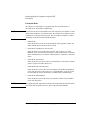
What are Sample Programs? . . . . . . . . . . . . . . . . . . . . . . . . . . . . . . . . . . . . . . . 4-4
Installation . . . . . . . . . . . . . . . . . . . . . . . . . . . . . . . . . . . . . . . . . . . . . . . . . . . . . . . 4-9
Required Equipment and Accessories . . . . . . . . . . . . . . . . . . . . . . . . . . . . . . . . 4-9
Installing the Sample Programs . . . . . . . . . . . . . . . . . . . . . . . . . . . . . . . . . . . . 4-10
Using sample1.vee . . . . . . . . . . . . . . . . . . . . . . . . . . . . . . . . . . . . . . . . . . . . . . . . 4-11
Program Execution Flow . . . . . . . . . . . . . . . . . . . . . . . . . . . . . . . . . . . . . . . . . 4-12
Panel Display . . . . . . . . . . . . . . . . . . . . . . . . . . . . . . . . . . . . . . . . . . . . . . . . . . 4-14
To Execute sample1.vee . . . . . . . . . . . . . . . . . . . . . . . . . . . . . . . . . . . . . . . . . . 4-15
Agilent 4155C/4156C VXIplug&play Driver User’s Guide, Edition 1
Contents-5
Contents
Using sample2.vee. . . . . . . . . . . . . . . . . . . . . . . . . . . . . . . . . . . . . . . . . . . . . . . .
Program Execution Flow . . . . . . . . . . . . . . . . . . . . . . . . . . . . . . . . . . . . . . . . .
Panel Display . . . . . . . . . . . . . . . . . . . . . . . . . . . . . . . . . . . . . . . . . . . . . . . . . .
To Execute sample2.vee. . . . . . . . . . . . . . . . . . . . . . . . . . . . . . . . . . . . . . . . . .
4-19
4-20
4-22
4-23
Customizing Sample Programs . . . . . . . . . . . . . . . . . . . . . . . . . . . . . . . . . . . . . .
To Change an GPIB Address . . . . . . . . . . . . . . . . . . . . . . . . . . . . . . . . . . . . .
To Change the Vth Measurement Setup. . . . . . . . . . . . . . . . . . . . . . . . . . . . . .
To Remove a Test Device . . . . . . . . . . . . . . . . . . . . . . . . . . . . . . . . . . . . . . . .
To Remove a Source Output . . . . . . . . . . . . . . . . . . . . . . . . . . . . . . . . . . . . . .
To Add a Test Device. . . . . . . . . . . . . . . . . . . . . . . . . . . . . . . . . . . . . . . . . . . .
To Add a Measurement Parameter. . . . . . . . . . . . . . . . . . . . . . . . . . . . . . . . . .
4-27
4-28
4-29
4-30
4-32
4-34
4-37
Contents-6
Agilent 4155C/4156C VXIplug&play Driver User’s Guide, Edition 1
1
Installation
Agilent 4155C/4156C VXIplug&play Driver User’s Guide, Edition 1
Installation
This chapter explains the environment requirements and installation of the
VXIplug&play driver for Agilent 4155/4156.
NOTE
•
“Software Requirements”
•
“Hardware Requirements with Agilent VEE”
•
“Installing 4155/4156 Driver”
The hardware required depends on the operating system and programming language
used. This manual provides hardware requirements when using the driver with
Agilent VEE software. When using the driver with a programming language other
than Agilent VEE, refer to the appropriate programming manual.
1-2
Agilent 4155C/4156C VXIplug&play Driver User’s Guide, Edition 1
Installation
Software Requirements
Software Requirements
The following software is required to use the VXIplug&play driver for the
4155/4156. You can select one from Windows NT and Windows 95. You can also
select the most comfortable programming language to develop and run programs.
•
•
Operating System
•
Windows NT revision 3.51 or later
•
Windows 95
32-bit VISA I/O Library
I/O Library for GPIB Interface Card, or equivalent
•
•
Programming Environment
•
Agilent VEE
•
Microsoft Visual Basic
•
Microsoft Visual C++
•
Borland C/C++
•
LabView
•
LabWindows
VXIplug&play Driver Disk (furnished with the 4155/4156)
•
4155/4156 Plug&Play Driver Disk
•
E5250A Plug&Play Driver Disk
NOTE
If you use the sample application programs, stored in the VEE Sample Program
Disk furnished with the 4155/4156, VEE software must be version 4.0 or later.
See Chapter 4. Also, if you use the Cascade Microtech Summit series semi-auto
prober, confirm the operating system supported by the prober control software
(PCS) supplied from Cascade Microtech, Inc. PCS version 2.50 supports Windows
95 and Windows 3.1.
NOTE
The E5250A Plug&Play Driver Disk stores the VXIplug&play driver for Agilent
E5250A. This driver is required to use the sample application programs.
Agilent 4155C/4156C VXIplug&play Driver User’s Guide, Edition 1
1-3
Installation
Hardware Requirements with Agilent VEE
Hardware Requirements with Agilent VEE
The following hardware is required to use Agilent VEE and the VXIplug&play
drivers.
•
•
•
•
Controller
•
486/66 with Coprocessor (minimum recommendation)
•
586(Pentium)/90 or better is recommended.
Memory
•
For Windows 95: 16 Mbyte. 24 Mbyte or more is recommended.
•
For Windows NT: 24 Mbyte. 32 Mbyte or more is recommended.
Hard disk (minimum disk space)
•
20 Mbytes for Agilent VEE (HP VEE version 4.0)
•
2 Mbytes for 4155/4156 driver
•
1 Mbyte for E5250A driver
Graphics
1024 × 768. 1280 × 1024 is recommended.
•
IEEE 488 Interface card
Agilent 82341C GPIB Interface Card, or equivalent.
•
CD-ROM drive
A CD-ROM drive will be required to install the software needed to use the
VXIplug&play driver.
•
Flexible disk drive
A 3.5 inch flexible disk drive is required to install the drivers.
1-4
Agilent 4155C/4156C VXIplug&play Driver User’s Guide, Edition 1
Installation
Installing 4155/4156 Driver
Installing 4155/4156 Driver
The installation flow for the VXIplug&play driver is shown below. If you have
already installed the IEEE 488 interface card, VISA I/O library, and programming
software on your PC, skip steps 1 through 4.
1. Install the IEEE 488 interface card into your PC.
See the interface card manual. Note the model number of the interface card, as
you may need it to configure the interface (in step 3).
2. Install VISA I/O library.
Follow the instructions in the I/O library’s setup program.
3. Configure and check the IEEE 488 interface.
See the I/O library manual. If you use the Agilent I/O Library, also see “To
Configure the Interface using Agilent I/O Library” on page 1-6.
4. Install the programming software.
Follow the setup program instructions.
5. Install the VXIplug&play driver.
See “To Install the Driver” on page 1-7.
6. Register the driver in the programming software.
See the programming software manual. If you are using Agilent VEE, also see
“Programming Basics” in Chapter 3.
Agilent 4155C/4156C VXIplug&play Driver User’s Guide, Edition 1
1-5
Installation
Installing 4155/4156 Driver
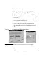
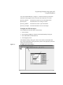
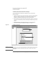
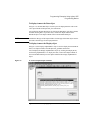
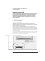
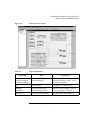
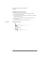
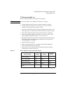
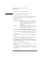
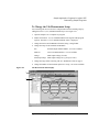
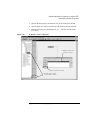
To Configure the Interface using Agilent I/O Library
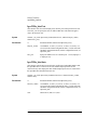
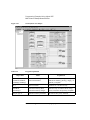
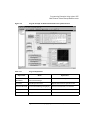
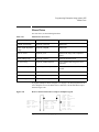
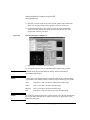
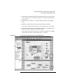
After installing the IEEE 488 interface card and the Agilent I/O Library, configure
the interface. The procedure shown below is the easiest way to configure the
interface. First, execute I_O Config in the HP I_O Libraries folder. The I/O Config
window is displayed. See Figure 1-1.
1. Click Auto Add.
If the interface card is installed properly, I_O Config automatically detects the
hardware configuration. The default names for SICL and VISA are assigned and
listed, as shown in the Configured Interface list.
2. Click hpib7 GPIB0.
3. Click Edit to display the Configuration dialog box for the interface card.
If you find any conflicts in the dialog box, such as IRQ line, you may need to
change them manually. Normally you can exit without modifying the default
setup.
4. Click OK to exit. Reboot your PC to configure the interface.
Figure 1-1
To Configure the Interface using Agilent I/O Library
NOTE
VISA Name is used by the VXIplug&play drivers to access the interface.
1-6
Agilent 4155C/4156C VXIplug&play Driver User’s Guide, Edition 1
Installation
Installing 4155/4156 Driver
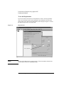
To Install the Driver
1. Insert the 4155/4156 Plug&Play Driver Disk into the flexible disk drive
connected to your PC.
2. Execute the 4156B.EXE program stored on the diskette. The program
automatically installs the driver in the following directory.
•
•
For Windows NT: \Vxipnp\Winnt\Hp4156b
For Windows 95: \Vxipnp\Win95\Hp4156b
Following files are installed in the directory.
• hp4156b.bas
• hp4156b.c
• hp4156b.def
• hp4156b.fp
• hp4156b.GID
• hp4156b.h
• hp4156b.hlp
• readme.txt
• DelsL1.isu
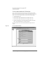
3. If you are also installing the driver for the E5250A, do the following.
a. Insert the E5250A Plug&Play Driver Disk into the flexible disk drive
connected to your PC.
b. Execute the E5250A.EXE program stored on the diskette. The program
automatically installs the driver in the following directory.
•
For Windows NT: \Vxipnp\Winnt\Hpe5250a
•
For Windows 95: \Vxipnp\Win95\Hpe5250a
Following files are installed in the directory.
• hpe5250a.bas
• hpe5250a.c
• hpe5250a.def
• hpe5250a.fp
• hpe5250a.GID
• hpe5250a.h
• hpe5250a.hlp
• readme.txt
• DelsL1.isu
Agilent 4155C/4156C VXIplug&play Driver User’s Guide, Edition 1
1-7
Installation
Installing 4155/4156 Driver
1-8
Agilent 4155C/4156C VXIplug&play Driver User’s Guide, Edition 1
2
Driver Functions
Agilent 4155C/4156C VXIplug&play Driver User’s Guide, Edition 1
Driver Functions
This section explains all the driver finctions available for Agilent 41555/4156 and
Agilent E5250A.
NOTE
•
“Driver Functions for the 4155/4156”
•
“Driver Functions for the E5250A”
For additional information on each function. refer to the on-line help for the
VXIplug&play drivers, or open the hp4156b.hlp or hpe5250a.hlp file in the
direcroty the driver is installed. See “Installing 4155/4156 Driver” in Chpater 1.
2-2
Agilent 4155C/4156C VXIplug&play Driver User’s Guide, Edition 1
Driver Functions
Driver Functions for the 4155/4156
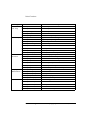
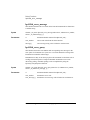
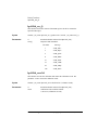
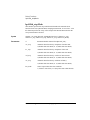
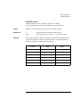
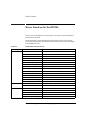
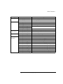
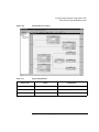
Table 2-1 lists all the functions for the 4155/4156. You will see a brief description of
the functions in the table.
For the description, syntax and parameters of the function, refer to the reference
section following this table. The driver functions in the reference section will appear
in the alphabetical order.
Table 2-1
Category
Miscellaneous
Primitive
Measurement
Functions
Calibration
Zero Offset
Cancel
4155/4156 Driver Function Lists
Function
hp4156b_init
hp4156b_close
hp4156b_reset
hp4156b_self_test
hp4156b_error_query
hp4156b_error_message
hp4156b_revision_query
hp4156b_timeOut
hp4156b_timeOut_Q
hp4156b_errorQueryDetect
hp4156b_errorQueryDetect_Q
hp4156b_dcl
hp4156b_esr_Q
hp4156b_readStatusByte_Q
hp4156b_opc_Q
hp4156b_startMeasure
hp4156b_readData
hp4156b_stopMode
hp4156b_abortMeasure
hp4156b_autoCal
hp4156b_execCal
hp4156b_offsetCancel
hp4156b_execOffsetCancel
Description
Initializes the 4155/4156.
Closes the connection with the 4155/4156.
Executes the 4155/4156 reset.
Executes the 4155/4156 self-test.
Queries the 4155/4156 for error code/message.
Queries for the driver errors.
Queries for the 4155/4156 firmware/driver revisions.
Sets the timeout.
Queries for the timeout setting.
Sets the automatic error checking.
Queries for the automatic error checking setting.
Sends the Device Clear.
Queries the ESR status.
Reads the 4155/4156 status byte.
Checks the 4155/4156 operation completion status.
Starts a measurement.
Reads a measurement result.
Sets the measurement completion mode.
Aborts output or measurement.
Sets the auto calibration mode
Executes the 4155/4156 calibration
Sets the zero offset cancel.
Executes the zero offset cancel.
Agilent 4155C/4156C VXIplug&play Driver User’s Guide, Edition 1
2-3
Driver Functions
Category
Measurement
Unit Setup
Source Setup
Measurement
Execution
Sampling
Measurements
Stress Force
Function
hp4156b_setSwitch
hp4156b_setFilter
hp4156b_setInteg
hp4156b_setVm
hp4156b_setPguR
hp4156b_force
hp4156b_forcePulse
hp4156b_zeroOutput
hp4156b_recoverOutput
hp4156b_setIv
hp4156b_setPbias
hp4156b_setPiv
hp4156b_setSweepSync
hp4156b_spotMeas
hp4156b_measureM
hp4156b_sweepIv
hp4156b_sweepMiv
hp4156b_measureP
hp4156b_sweepPiv
hp4156b_sweepPbias
hp4156b_setSample
hp4156b_addSampleSynclv
hp4156b_addSampleSyncPulse
hp4156b_sample
hp4156b_clearSampleSync
hp4156b_setStress
hp4156b_addStressSyncIv
hp4156b_addStressSyncPulse
hp4156b_stress
hp4156b_clearStressSync
2-4
Description
Sets the output switch.
Sets the output filter.
Sets the integration time.
Sets the VMU measurement mode.
Sets the PGU output impedance.
Applies a dc current or voltage.
Applies a pulse by using PGU.
Disables output.
Recovers output.
Sets the sweep source.
Sets the pulsed bias source.
Sets the pulsed sweep source.
Sets the synchronous sweep source.
Executes a high speed spot measurement.
Executes a multi-channel spot measurement.
Executes a one channel sweep measurement.
Executes a multi-channel sweep measurement.
Executes a pulsed spot measurement.
Executes a pulsed sweep measurement.
Executes a sweep measurement with pulsed bias.
Sets the timing parameters.
Sets the dc source.
Sets the pulse source.
Executes a sampling measurement.
Clears the source setup.
Sets the timing parameters.
Sets the dc stress source.
Sets the pulse stress source.
Forces stress.
Clears the source setup.
Agilent 4155C/4156C VXIplug&play Driver User’s Guide, Edition 1
Driver Functions
Category
Passthrough
Functions
Function
hp4156b_cmd
h4156b_cmdInt
hp4156b_cmdReal
hp4156b_cmdData_Q
hp4156b_cmdString_Q
hp4156b_cmdInt16_Q
hp4156b_cmdInt16Arr_Q
hp4156b_cmdInt32_Q
hp4156b_cmdInt32Arr_Q
hp4156b_cmdReal64_Q
hp4156b_cmdReal64Arr_Q
Description
Sends a command.
Sends a command with an integer parameter.
Sends a command with a real parameter.
Sends a command to read any data.
Sends a command to read string response.
Sends a command to read 16 bit integer response.
Sends a command to read 16 bit integer array response.
Sends a command to read 32 bit integer response.
Sends a command to read 32 bit integer array response.
Sends a command to read 64 bit real response.
Sends a command to read 64 bit real array response.
Agilent 4155C/4156C VXIplug&play Driver User’s Guide, Edition 1
2-5
Driver Functions
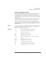
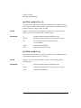
hp4156b_abortMeasure
hp4156b_abortMeasure
This function aborts the 4155/4156’s present operation, such as the measurement
executed by the hp4156b_startMeasure function, the pulse output by the
hp4156b_forcePulse function, the stress force by the hp4156b_stress function, and
so on.
Syntax
ViStatus _VI_FUNC hp4156b_abortMeasure(ViSession vi);
Parameters
vi
Instrument handle returned from hp4156b_init( ).
hp4156b_addSampleSyncIv
This function specifies the constant current source or constant voltage source used
for the sampling measurements, and sets the parameters. Source output starts at the
beginning of the sampling measurement (beginning of the hold time), and stops at
the end of the last sampling measurement point.
Sampling measurement channels are defined by the hp4156b_sample function, and
sampling measurement timing is defined by the hp4156b_setSample function.
Syntax
ViStatus _VI_FUNC hp4156b_addSampleSyncIv(ViSession vi, ViInt32 channel,
ViInt32 mode, ViReal64 range, ViReal64 base, ViReal64 bias, ViReal64 comp);
Parameters
vi
Instrument handle returned from hp4156b_init( ).
channel
Channel number of the source unit. 1 to 6 (SMU1 to SMU6),
21 (VSU1), 22 (VSU2), 27 (PGU1), or 28 (PGU2)
mode
Output mode. 1 (current output, only for SMU) or 2 (voltage
output).
range
Output range. 0 (auto ranging) or positive value (limited auto
ranging). See below.
For current output:
1E-11 to 1.0 A, or 0.
For voltage output:
2.0 to 200.0 V, or 0.
base
Base value. -1.0 to 1.0 A for current output, -200.0 V to 200.0 V
for voltage output.
bias
Bias value. -1.0 to 1.0 A for current output, -200.0 V to 200.0 V
for voltage output.
comp
Compliance value. -200.0 V to 200.0 V for voltage compliance,
-1.0 to 1.0 A for current compliance.
2-6
Agilent 4155C/4156C VXIplug&play Driver User’s Guide, Edition 1
Driver Functions
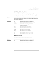
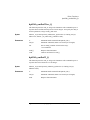
hp4156b_addSampleSyncPulse
hp4156b_addSampleSyncPulse
This function specifies the pulse source (PGU) used for the sampling measurements,
and sets the parameters. Pulse outputs start at the beginning of the sampling
measurement (beginning of the hold time), and stop at the end of the last sampling
measurement point or stop at the last pulse if it comes earlier than the last sampling
measurement point.
Sampling measurement channels are defined by the hp4156b_sample function, and
sampling measurement timing is defined by the hp4156b_setSample function.
If you want to let the pulse output synchronize with the sampling measurement
timing, you should define carefully both the hp4156b_addSampleSyncPulse timing
parameters (count, period, width, delay, rise and fall) and the hp4156b_setSample
timing parameters.
Syntax
ViStatus _VI_FUNC hp4156b_addSampleSyncPulse(ViSession vi, ViInt32 channel,
ViReal64 base, ViReal64 peak, ViInt32 count, ViReal64 period, ViReal64 width,
ViReal64 delay, ViReal64 rise, ViReal64 fall);
Parameters
vi
Instrument handle returned from hp4156b_init( ).
channel
Channel number of the pulse generator unit.
27 (PGU1) or 28 (PGU2)
base
Pulse base value. -40.0 to 40.0 V.
peak
Pulse peak value. -40.0 to 40.0 V.
count
Pulse count (number of pulses). 1 to 65535, or 0 (free run
mode).
period
Pulse period. 1E-6 to 10.0 seconds.
width
Pulse width. 1E-6 to 9.99 seconds.
delay
Pulse delay time. 0.0 to 10.0 seconds.
rise
Pulse leading time. 0.1E-6 to 10E-3 seconds.
fall
Pulse trailling time. 0.1E-6 to 10E-3 seconds.
Agilent 4155C/4156C VXIplug&play Driver User’s Guide, Edition 1
2-7
Driver Functions
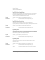
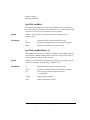
hp4156b_addStressSyncIv
hp4156b_addStressSyncIv
This function specifies the DC stress source, and sets the parameters. You can use
maximum 4 stress sources at once by using the hp4156b_addStressSyncIv and/or
hp4156b_addStressSyncPulse functions.
Syntax
ViStatus _VI_FUNC hp4156b_addStressSyncIv(ViSession vi, ViInt32 source,
ViInt32 channel, ViInt32 mode, ViReal64 range, ViReal64 base, ViReal64 stress,
ViReal64 comp);
Parameters
vi
Instrument handle returned from hp4156b_init( ).
source
Reference number of the stress source. 1, 2, 3, or 4.
channel
Channel number of the stress source.
1 to 6 (SMU1 to SMU6), 21 (VSU1), 22 (VSU2), 27 (PGU1),
or 28 (PGU2)
mode
Output mode. 1 (current output, only for SMU) or 2 (voltage
output).
range
Output range. 0 (auto ranging) or positive value (limited auto
ranging). See below.
For current output:
1E-11 to 1.0 A, or 0.
For voltage output:
2.0 to 200.0 V, or 0.
base
Base value. -1.0 to 1.0 A for current output, -200.0 V to 200.0 V
for voltage output.
stress
Stress value. -1.0 to 1.0 A for current output, -200.0 V to 200.0
V for voltage output.
comp
Compliance value. -200.0 V to 200.0 V for voltage compliance,
-1.0 to 1.0 A for current compliance.
2-8
Agilent 4155C/4156C VXIplug&play Driver User’s Guide, Edition 1
Driver Functions
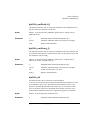
hp4156b_addStressSyncPulse
hp4156b_addStressSyncPulse
This function specifies the pulse stress source (PGU), and sets the parameters. You
can use maximum 4 stress sources at once by using the hp4156b_addStressSyncIv
and/or hp4156b_addStressSyncPulse functions. See “hp4156b_stress” on page 41
for the setting of width and delay.
Syntax
ViStatus _VI_FUNC hp4156b_addStressSyncPulse(ViSession vi, ViInt32 source,
ViInt32 channel, ViReal64 base, ViReal64 stress, ViReal64 width, ViReal64 delay,
ViReal64 rise, ViReal64 fall);
Parameters
vi
Instrument handle returned from hp4156b_init( ).
source
Reference number of the stress source. 1, 2, 3, or 4.
channel
Channel number of the pulse generator unit.
27 (PGU1) or 28 (PGU2)
base
Stress pulse base value. -40.0 to 40.0 V.
stress
Stress pulse peak value. -40.0 to 40.0 V.
width
Pulse width. 1E-6 to 9.99 seconds.
delay
Pulse delay time. 0.0 to 10.0 seconds.
rise
Pulse leading time. 0.1E-6 to 10E-3 seconds.
fall
Pulse trailling time. 0.1E-6 to 10E-3 seconds.
hp4156b_autoCal
This function enables or disables the auto calibration function.
Syntax
ViStatus _VI_FUNC hp4156b_autoCal(ViSession vi, ViInt32 state);
Parameters
vi
Instrument handle returned from hp4156b_init( ).
state
Auto calibration mode. 0 (OFF) or 1 (ON).
Agilent 4155C/4156C VXIplug&play Driver User’s Guide, Edition 1
2-9
Driver Functions
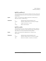
hp4156b_clearSampleSync
hp4156b_clearSampleSync
This function clears the settings of the constant voltage/current source defined by
the hp4156b_addSampleSyncIv function, and the settings of the pulse source
defined by the hp4156b_addSampleSyncPulse function.
Syntax
ViStatus _VI_FUNC hp4156b_clearSampleSync(ViSession vi);
Parameters
vi
Instrument handle returned from hp4156b_init( ).
hp4156b_clearStressSync
This function clears the settings of the stress sources defined by the
hp4156b_addStressSyncIv function and the hp4156b_addStressSyncPulse function.
Syntax
ViStatus _VI_FUNC hp4156b_clearStressSync(ViSession vi);
Parameters
vi
Instrument handle returned from hp4156b_init( ).
hp4156b_close
This function terminates the software connection to the instrument and deallocates
system resources. It is generally a good programming habit to close the instrument
handle when the program is done using the instrument.
Syntax
ViStatus _VI_FUNC hp4156b_close(ViSession vi);
Parameters
vi
Instrument handle returned from hp4156b_init( ).
hp4156b_cmd
This function passes the cmd_str string to the instrument. Must be a NULL
terminated C string.
Syntax
ViStatus _VI_FUNC hp4156b_cmd(ViSession vi, ViString cmd_str);
Parameters
vi
Instrument handle returned from hp4156b_init( ).
cmd_str
Instrument command (cannot exceed 256 bytes in length).
2-10
Agilent 4155C/4156C VXIplug&play Driver User’s Guide, Edition 1
Driver Functions
hp4156b_cmdData_Q
hp4156b_cmdData_Q
This function passes the cmd_str string to the instrument. This entry point will wait
for a response which may be any data. You specify the cmd_str and size parameters,
and get result[ ].
Syntax
ViStatus _VI_FUNC hp4156b_cmdData_Q(ViSession vi, ViString cmd_str,
ViInt32 size, ViChar _VI_FAR result[ ] );
Parameters
vi
Instrument handle returned from hp4156b_init( ).
cmd_str
Instrument command (cannot exceed 256 bytes in length).
size
Length of result in bytes. 2 to 32767.
result[ ]
Response from instrument.
hp4156b_cmdInt
This function passes the cmd_str string to the instrument. This entry point passes
the string in cmd_str followed by a space and then the integer in value. Note that
either an Int16 or 32 can be passed as the Int16 will be promoted.
Syntax
ViStatus _VI_FUNC hp4156b_cmdInt(ViSession vi, ViString cmd_str,
ViInt32 value);
Parameters
vi
Instrument handle returned from hp4156b_init( ).
cmd_str
Instrument command (cannot exceed 256 bytes in length).
value
Parameter for command. -2147483647 to 2147483647.
Agilent 4155C/4156C VXIplug&play Driver User’s Guide, Edition 1
2-11
Driver Functions
hp4156b_cmdInt16Arr_Q
hp4156b_cmdInt16Arr_Q
This function passes the cmd_str string to the instrument. This command expects a
response that is a definite arbitrary block of 16 bit integers. You specify the cmd_str
and size parameters, and get result[ ] and count.
Syntax
ViStatus _VI_FUNC hp4156b_cmdInt16Arr_Q(ViSession vi, ViString cmd_str,
ViInt32 size, ViInt16 _VI_FAR result[ ], ViPInt32 count);
Parameters
vi
Instrument handle returned from hp4156b_init( ).
cmd_str
Instrument command (cannot exceed 256 bytes in length).
size
Size of result[ ] (number of items in the array).
1 to 2147483647.
result[ ]
Response from instrument.
count
Count of valid items in result[ ].
hp4156b_cmdInt16_Q
This function passes the cmd_str string to the instrument. This command expects a
response that can be returned as a 16 bit integer.
Syntax
ViStatus _VI_FUNC hp4156b_cmdInt16_Q(ViSession vi, ViString cmd_str,
ViPInt16 result);
Parameters
vi
Instrument handle returned from hp4156b_init( ).
cmd_str
Instrument command (cannot exceed 256 bytes in length).
result
Response from instrument.
2-12
Agilent 4155C/4156C VXIplug&play Driver User’s Guide, Edition 1
Driver Functions
hp4156b_cmdInt32Arr_Q
hp4156b_cmdInt32Arr_Q
This function passes the cmd_str string to the instrument. This command expects a
response that is a definite arbitrary block of 32 bit integers. You specify the cmd_str
and size parameters, and get result[ ] and count.
Syntax
ViStatus _VI_FUNC hp4156b_cmdInt32Arr_Q(ViSession vi, ViString cmd_str,
ViInt32 size, ViInt32 _VI_FAR result[ ], ViPInt32 count);
Parameters
vi
Instrument handle returned from hp4156b_init( ).
cmd_str
Instrument command (cannot exceed 256 bytes in length).
size
Size of result[ ] (number of items in the array).
1 to 2147483647.
result[ ]
Response from instrument.
count
Count of valid items in result[ ].
hp4156b_cmdInt32_Q
This function passes the cmd_str string to the instrument. This command expects a
response that can be returned as a 32 bit integer.
Syntax
ViStatus _VI_FUNC hp4156b_cmdInt32_Q(ViSession vi, ViString cmd_str,
ViPInt32 result);
Parameters
vi
Instrument handle returned from hp4156b_init( ).
cmd_str
Instrument command (cannot exceed 256 bytes in length).
result
Response from instrument.
Agilent 4155C/4156C VXIplug&play Driver User’s Guide, Edition 1
2-13
Driver Functions
hp4156b_cmdReal
hp4156b_cmdReal
This function passes the cmd_str string to the instrument. This entry point passes
the string in cmd_str followed by a space and then the real in value. Note that either
an Real32 or 64 can be passed as the Real32 will be promoted.
Syntax
ViStatus _VI_FUNC hp4156b_cmdReal(ViSession vi, ViString cmd_str,
ViReal64 value);
Parameters
vi
Instrument handle returned from hp4156b_init( ).
cmd_str
Instrument command (cannot exceed 256 bytes in length).
value
Parameter for command. -1E+300 to 1E+300.
hp4156b_cmdReal64Arr_Q
This function passes the cmd_str string to the instrument. This command expects a
response that is a definite arbitrary block of 64 bit reals. You specify the cmd_str
and size parameters, and get result[ ] and count.
Syntax
ViStatus _VI_FUNC hp4156b_cmdReal64Arr_Q(ViSession vi, ViString cmd_str,
ViInt32 size, ViReal64 _VI_FAR result[ ], ViPInt32 count);
Parameters
vi
Instrument handle returned from hp4156b_init( ).
cmd_str
Instrument command (cannot exceed 256 bytes in length).
size
Size of result[ ] (number of items in the array).
1 to 2147483647.
result[ ]
Response from instrument.
count
Count of valid items in result[ ].
2-14
Agilent 4155C/4156C VXIplug&play Driver User’s Guide, Edition 1
Driver Functions
hp4156b_cmdReal64_Q
hp4156b_cmdReal64_Q
This function passes the cmd_str string to the instrument. This command expects a
response that can be returned as a 64 bit real.
Syntax
ViStatus _VI_FUNC hp4156b_cmdReal64_Q(ViSession vi, ViString cmd_str,
ViPReal64 result);
Parameters
vi
Instrument handle returned from hp4156b_init( ).
cmd_str
Instrument command (cannot exceed 256 bytes in length).
result
Response from instrument.
hp4156b_cmdString_Q
This function passes the cmd_str string to the instrument. This entry point will wait
for a response which must be a string (character data). You specify the cmd_str and
size parameters, and get result[ ].
Syntax
ViStatus _VI_FUNC hp4156b_cmdString_Q(ViSession vi, ViString cmd_str,
ViInt32 size, ViChar _VI_FAR result[ ] );
Parameters
vi
Instrument handle returned from hp4156b_init( ).
cmd_str
Instrument command (cannot exceed 256 bytes in length).
size
Length of result in bytes. 2 to 32767.
result[ ]
Response from instrument.
hp4156b_dcl
This function sends a device clear (DCL) to the instrument.
A device clear will abort the present operation and enable the instrument to accept a
new command or query. This is particularly useful in situations where it is not
possible to determine the instrument state. In this case, it is customary to send a
device clear before issuing a new instrument driver function. The device clear
ensures that the instrument will be able to begin processing the new commands.
Syntax
ViStatus _VI_FUNC hp4156b_dcl(ViSession vi);
Parameters
vi
Instrument handle returned from hp4156b_init( ).
Agilent 4155C/4156C VXIplug&play Driver User’s Guide, Edition 1
2-15
Driver Functions
hp4156b_error_message
hp4156b_error_message
This function translates the error return value from an instrument driver function to
a readable string.
Syntax
ViStatus _VI_FUNC hp4156b_error_message(ViSession vi, ViStatus error_number,
ViChar _VI_FAR message[ ] );
Parameters
vi
Instrument handle returned from hp4156b_init( ).
error_number
Error return value from the driver function.
message[ ]
Error message string. This is limited to 256 characters.
hp4156b_error_query
This function returns the error numbers and corresponding error messages in the
error queue of a instrument. See If You Have a Problem manual for a listing of the
instrument error numbers and messages.
Instrument errors may occur when you places the instrument in a bad state such as
sending an invalid sequence of coupled commands. Instrument errors can be
detected by polling. Automatic polling can be accomplished by using the
hp4156b_errorQueryDetect function.
Syntax
ViStatus _VI_FUNC hp4156b_error_query(ViSession vi, ViPInt32 error_number,
ViChar _VI_FAR error_message[ ] );
Parameters
vi
Instrument handle returned from hp4156b_init( ).
error_number
Instrument’s error code.
error_message[ ]
Instrument’s error message. This is limited to 256 characters.
2-16
Agilent 4155C/4156C VXIplug&play Driver User’s Guide, Edition 1
Driver Functions
hp4156b_errorQueryDetect
hp4156b_errorQueryDetect
This function enables or disables automatic instrument error checking.
If automatic error checking is enabled then the driver will query the instrument for
an error at the end of each function call.
Syntax
ViStatus _VI_FUNC hp4156b_errorQueryDetect(ViSession vi,
ViBoolean errorQueryDetect);
Parameters
vi
Instrument handle returned from hp4156b_init( ).
errorQueryDetect
Error checking enable (VI_TRUE) or disable (VI_FALSE).
hp4156b_errorQueryDetect_Q
This function indicates if automatic instrument error detection is enabled or
disabled.
Syntax
ViStatus _VI_FUNC hp4156b_errorQueryDetect_Q(ViSession vi,
ViPBoolean pErrDetect);
Parameters
vi
Instrument handle returned from hp4156b_init( ).
pErrDetect
Error checking enable (VI_TRUE) or disable (VI_FALSE).
Agilent 4155C/4156C VXIplug&play Driver User’s Guide, Edition 1
2-17
Driver Functions
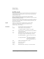
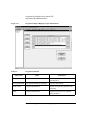
hp4156b_esr_Q
hp4156b_esr_Q
This function returns the contents of the ESR register. The driver returns the
equivalent messages:
Syntax
ViStatus _VI_FUNC hp4156b_esr_Q(ViSession vi, ViChar _VI_FAR errstr[ ] );
Parameters
vi
Instrument handle returned from hp4156b_init( ).
errstr[ ]
Response from instrument.
Bit Value
Message
1
“ESR_OPC”
2
“ESR_RQL”
4
“ESR_QYE”
8
“ESR_DDE”
16
“ESR_EXE”
32
“ESR_CME”
64
“ESR_URQ”
128
“ESR_PON”
hp4156b_execCal
This function executes the calibration and returns the calibration result. The
parameter “result” returns the calibration result.
Syntax
ViStatus _VI_FUNC hp4156b_execCal(ViSession vi, ViPInt32 result);
Parameters
vi
Instrument handle returned from hp4156b_init( ).
result
Calibration result. Numeric number.
0: No error (calibration succeed).
2-18
Agilent 4155C/4156C VXIplug&play Driver User’s Guide, Edition 1
Driver Functions
hp4156b_execOffsetCancel
hp4156b_execOffsetCancel
This function measures the zero offset data, and sets the zero offset function to ON.
The parameter 'channel' specifies the measurement channel (SMU or VMU).
If you define SMU for 'channel', the SMU must be set to the voltage force mode by
using the hp4156b_force function, before executing this function.
If you define VMU for 'channel’, the VMU must be set to the differential voltage
measurement mode by using the hp4156b_setVm function, before executing this
function.
Syntax
ViStatus _VI_FUNC hp4156b_execOffsetCancel(ViSession vi, ViInt32 channel,
ViInt32 range);
Parameters
vi
Instrument handle returned from hp4156b_init( ).
channel
Channel number of the unit to measure the zero offset data..
1 to 6 (SMU1 to SMU6), 23 (VMU1), or 24 (VMU2).
range
Measurement range to measure the zero offset data
0 (10 pA range for SMU), 1 (100 pA range for SMU),
2 (1 nA range for SMU), or 3 (0.2 V range for VMU).
Agilent 4155C/4156C VXIplug&play Driver User’s Guide, Edition 1
2-19
Driver Functions
hp4156b_force
hp4156b_force
This function specifies the dc current source (SMU) or dc voltage source (SMU,
VSU, or PGU), and forces the output immediately. To stop the output, use the
hp4156b_force function with 0 (zero) output.
Syntax
ViStatus _VI_FUNC hp4156b_force(ViSession vi, ViInt32 channel, ViInt32 mode,
ViReal64 range, ViReal64 value, ViReal64 comp, ViInt32 polarity);
Parameters
vi
Instrument handle returned from hp4156b_init( ).
channel
Channel number of the source unit.
1 to 6 (SMU1 to SMU6), 21 (VSU1), 22 (VSU2), 27 (PGU1),
or 28 (PGU2)
mode
Output mode. 1 (current output, only for SMU) or 2 (voltage
output).
range
Output range. 0 (auto ranging) or positive value (limited auto
ranging). See below.
For current output:
1E-11 to 1.0 A, or 0.
For voltage output:
2.0 to 200.0 V, or 0.
value
Output value. -1.0 to 1.0 A for current output, -200.0 to 200.0 V
for SMU voltage output, -40 to 40 V for PGU dc voltage output,
-20 to 20 V for VSU output.
comp
Compliance value (only for SMU). -200.0 V to 200.0 V for
voltage compliance, -1.0 to 1.0 A for current compliance.
polarity
Compliance polarity (only for SMU). 0 (auto) or 1 (manual).
If you select 1, polarity is set to the same polarity as comp value
you enterd.
2-20
Agilent 4155C/4156C VXIplug&play Driver User’s Guide, Edition 1
Driver Functions
hp4156b_forcePulse
hp4156b_forcePulse
This function specifies the pulse source (PGU) settings and forces the voltage pulse
immediately. To stop the pulse output, use hp4156b_abortMeasure function.
Syntax
ViStatus _VI_FUNC hp4156b_forcePulse(ViSession vi, ViInt32 channel,
ViInt32 count, ViReal64 base, ViReal64 peak, ViReal64 width, ViReal64 period,
ViReal64 delay, ViReal64 rise, ViReal64 fall);
Parameters
vi
Instrument handle returned from hp4156b_init( ).
channel
Channel number of the pulse generator unit.
27 (PGU1) or 28 (PGU2)
count
Pulse count (number of pulses). 1 to 65535, or 0 (free run
mode).
base
Pulse base value. -40.0 to 40.0 V.
peak
Pulse peak value. -40.0 to 40.0 V.
width
Pulse width. 1E-6 to 9.99 seconds.
period
Pulse period. 1E-6 to 10.0 seconds.
delay
Pulse delay time. 0.0 to 10.0 seconds.
rise
Pulse leading time. 0.1E-6 to 10E-3 seconds.
fall
Pulse trailling time. 0.1E-6 to 10E-3 seconds.
Agilent 4155C/4156C VXIplug&play Driver User’s Guide, Edition 1
2-21
Driver Functions
hp4156b_init
hp4156b_init
This function initializes the software connection to the instrument and optionally
verifies that instrument is in the system. In addition, it may perform any necessary
actions to place the instrument in its reset state.
If the hp4156b_init function encounters an error, then the value of the vi output
parameter will be VI_NULL.
Syntax
ViStatus _VI_FUNC hp4156b_init(ViRsrc InstrDesc, ViBoolean id_query,
ViBoolean do_reset, ViPSession vi);
Parameters
InstrDesc
Instrument description. Examples; GPIB0::1::INSTR.
id_query
VI_TRUE (to perform system verification), or
VI_FALSE (do not perform system verification).
do_reset
VI_TRUE (to perform reset operation), or
VI_FALSE (do not perform reset operation).
vi
Instrument handle. This is VI_NULL if an error occurred
during the init.
2-22
Agilent 4155C/4156C VXIplug&play Driver User’s Guide, Edition 1
Driver Functions
hp4156b_measureM
hp4156b_measureM
This function executes a multi channel spot measurement by the specified units, and
returns the measured value and the measurement status.
The array size of all arrays should be the same together. Then the order of the array
data is important. For example, the measurement setup for the unit specified by
channel[1] must be entered into mode[1] and range[1]. And the measured data and
status data of the units specified by channel[1] will be returned by value[1] and
status[1], respectively.
Syntax
ViStatus _VI_FUNC hp4156b_measureM(ViSession vi, ViInt32 channel[ ],
ViInt32 mode[ ], ViReal64 range[ ], ViReal64 value[ ], ViInt32 status[ ] );
Parameters
vi
Instrument handle returned from hp4156b_init( ).
channel[ ]
Channel number of the measurement unit. Enter 0 (zero) at the
end of the unit definition for channel[ ]. For example, if you use
two units, the first and second elements of channel[ ] must
specify the units, and the third element must be 0.
1 to 6 (SMU1 to SMU6), 23 (VMU1), or 24 (VMU2).
mode[ ]
Measurement mode.
1 (current measurement) or 2 (voltage measurement).
range[ ]
Measurement range. 0 (auto ranging), positive value (limited
auto ranging), or negative value (fixed range). See below.
For current measurement:
-1E-11 to -1.0 A, 1E-11 to 1.0 A,
or 0.
For voltage measurement: -2.0 to -200.0 V, 2.0 to 200.0 V
(-0.2 and 0.2 are available for
VMU in differential mode), or 0.
value[ ]
Measurement data.
status[ ]
Measurement status. 0 (no error), or 1 to 255 (error status).
Agilent 4155C/4156C VXIplug&play Driver User’s Guide, Edition 1
2-23
Driver Functions
hp4156b_measureP
hp4156b_measureP
This function executes a pulsed spot measurement by the specified channel, and
returns the measured value and the measurement status.
Syntax
ViStatus _VI_FUNC hp4156b_measureP(ViSession vi, ViInt32 channel,
ViInt32 mode, ViReal64 range, ViPReal64 value, ViPInt32 status);
Parameters
vi
Instrument handle returned from hp4156b_init( ).
channel
Channel number of the measurement unit.
1 to 6 (SMU1 to SMU6), 23 (VMU1), or 24 (VMU2).
mode
Measurement mode. 1 (current measurement, only for SMU) or
2 (voltage measurement).
range
Measurement range. 0 (auto ranging), positive value (limited
auto ranging), or negative value (fixed range). See below.
For current measurement:
-1E-11 to -1.0 A, 1E-11 to 1.0 A,
or 0.
For voltage measurement: -2.0 to -200.0 V, 2.0 to 200.0 V
(-0.2 and 0.2 are available for
VMU in differential mode), or 0.
value
Measurement data.
status
Measurement status. 0 (no error), or 1 to 255 (error status).
hp4156b_offsetCancel
This function enables or disables the zero offset cancel function.
Syntax
ViStatus _VI_FUNC hp4156b_offsetCancel(ViSession vi, ViInt32 channel,
ViInt32 state);
Parameters
vi
Instrument handle returned from hp4156b_init( ).
channel
Channel number of the unit to set the offset cancel function.
1 to 6 (SMU1 to SMU6), 23 (VMU1), or 24 (VMU2).
state
2-24
0 (Function OFF), or 1 (Function ON).
Agilent 4155C/4156C VXIplug&play Driver User’s Guide, Edition 1
Driver Functions
hp4156b_opc_Q
hp4156b_opc_Q
This function does the *OPC? common command.
Syntax
ViStatus _VI_FUNC hp4156b_opc_Q(ViSession vi, ViPBoolean result);
Parameters
vi
Instrument handle returned from hp4156b_init( ).
result
VI_TRUE (Operation complete), or
VI_FALSE (Operation is pending).
hp4156b_readData
This function reads and returns the source setup data or the data measured by the
hp4156b_startMeasure function.
Syntax
ViStatus _VI_FUNC hp4156b_readData(ViSession vi, ViPInt32 eod,
ViPInt32 data_type, ViPReal64 value, ViPInt32 status, ViPInt32 channel);
Parameters
vi
Instrument handle returned from hp4156b_init( ).
eod
End of data flag. 0 (not end of data), or 1 (end of data).
data_type
Data type of the value. 0 (Voltage setup data),
1 (Current setup data), 3 (Time setup data),
8 (Voltage measurement data), 9 (Current measurement data),
11 (Time measurement data), 14 (Sampling index data), or
15 (Stress status data).
value
Measurement data or source setup data.
status
Measurement status or source status.
channel
Channel number of the unit for measurement or output.
1 to 6 (SMU1 to SMU6), 21 (VSU1), 22 (VSU2), 23 (VMU1),
24 (VMU2), 27 (PGU1) or 28 (PGU2).
Agilent 4155C/4156C VXIplug&play Driver User’s Guide, Edition 1
2-25
Driver Functions
hp4156b_readStatusByte_Q
hp4156b_readStatusByte_Q
This function returns the contents of the status byte register.
Syntax
ViStatus _VI_FUNC hp4156b_readStatusByte_Q(ViSession vi,
ViPInt16 statusByte);
Parameters
vi
Instrument handle returned from hp4156b_init( ).
statusByte
The contents of the status byte are returned in this parameter.
hp4156b_recoverOutput
This function returns the unit to the settings that are stored by the
hp4156b_zeroOutput function, and clears the stored unit settings.
Syntax
ViStatus _VI_FUNC hp4156b_recoverOutput(ViSession vi, ViInt32 channel);
Parameters
vi
Instrument handle returned from hp4156b_init( ).
channel
Channel number of the unit to return the settings. 1 to 6 (SMU1
to SMU6), 21 (VSU1), 22 (VSU2), 27 (PGU1) or 28 (PGU2).
hp4156b_reset
This function places the instrument in a default state. Before issuing this function, it
may be necessary to send a device clear to ensure that the instrument can execute a
reset. A device clear can be issued by invoking hp4156b_dcl function.
Syntax
ViStatus _VI_FUNC hp4156b_reset(ViSession vi);
Parameters
vi
2-26
Instrument handle returned from hp4156b_init( ).
Agilent 4155C/4156C VXIplug&play Driver User’s Guide, Edition 1
Driver Functions
hp4156b_revision_query
hp4156b_revision_query
This function returns the driver revision and the instrument firmware revision.
Syntax
ViStatus _VI_FUNC hp4156b_revision_query(ViSession vi,
ViChar_VI_FAR driver_rev[ ] , ViChar _VI_FAR instr_rev[ ] );
Parameters
vi
Instrument handle returned from hp4156b_init( ).
driver_rev[ ]
Instrument driver revision. This is limited to 256 characters.
instr_rev[ ]
Instrument firmware revision. This is limited to 256 characters.
Agilent 4155C/4156C VXIplug&play Driver User’s Guide, Edition 1
2-27
Driver Functions
hp4156b_sample
hp4156b_sample
This function executes a sampling measurement by the specified channels, and
returns the number of measurement points, measurement data index, measurement
data and the measurement status.
Before executing this function, set the sampling timing by using the
hp4156b_setSample function. The synchronous dc sources used with the sampling
measurement units are defined by using the hp4156b_addSampleSyncIv function.
And the synchronous pulsed sources used with the sampling measurement units are
defined by using the hp4156b_addSampleSyncPulse function.
Syntax
ViStatus _VI_FUNC hp4156b_sample(ViSession vi, ViInt32 channel[ ],
ViInt32 mode[ ], ViReal64 range[ ], ViPInt32 point, ViInt32 index[ ],
ViReal64 value[ ], ViInt32 status[ ] );
Parameters
vi
Instrument handle returned from hp4156b_init( ).
channel[ ]
Channel number of the measurement unit.
1 to 6 (SMU1 to SMU6), 23 (VMU1), or 24 (VMU2).
mode[ ]
Measurement mode. 1 (current measurement, only for SMU) or
2 (voltage measurement).
range[ ]
Measurement range. 0 (auto ranging), positive value (limited
auto ranging), or negative value (fixed range). See below.
For current measurement:
-1E-11 to -1.0 A, 1E-11 to 1.0 A,
or 0.
For voltage measurement: -2.0 to -200.0 V, 2.0 to 200.0 V
(-0.2 and 0.2 are available for
VMU in differential mode), or 0.
point
Number of measurement points. 1 to 10001.
index[ ]
Measurement data index.
value[ ]
Measurement data.
status[ ]
Measurement status. 0 (no error), or 1 to 255 (error status).
2-28
Agilent 4155C/4156C VXIplug&play Driver User’s Guide, Edition 1
Driver Functions
hp4156b_self_test
Remarks
The array size of the parameters should be as shown below.
ViInt32
channel[N]
ViInt32
mode[N]
ViReal64 range[N]
ViInt32
point
ViInt32
index[M]
ViReal64 value[M][N]
ViReal64 status[M][N]
where,
N: Number of channels used for the measurements plus 1, or more.
M: Number of sweep points ('point’ parameter value of hp4156b_setSample
function), or more.
For the parameter definition, the order of the array data is important. For example,
the measurement setup for the unit specified by channel[1] must be entered into
mode[1] and range[1]. And measurement data and status data of the unit specified
by channel[1] will be returned by value[M][1] and status[M][1], respectively.
hp4156b_self_test
This function causes the instrument to perform a self-test and returns the result of
that self-test. This is used to verify that an instrument is operating properly. A failure
may indicate a potential hardware problem.
Syntax
ViStatus _VI_FUNC hp4156b_self_test(ViSession vi, ViPInt16 test_result,
ViChar_VI_FAR test_message[ ] );
Parameters
vi
Instrument handle returned from hp4156b_init( ).
test_result
Numeric result from self-test operation. 0: No error.
test_message[ ]
Self-test status message. This is limited to 256 characters.
Agilent 4155C/4156C VXIplug&play Driver User’s Guide, Edition 1
2-29
Driver Functions
hp4156b_setFilter
hp4156b_setFilter
This function sets the output filter of the specified channel.
Syntax
ViStatus _VI_FUNC hp4156b_setFilter(ViSession vi, ViInt32 channel,
ViInt32 state);
Parameters
vi
Instrument handle returned from hp4156b_init( ).
channel
Channel number of the unit. 1 (SMU1), 2, 3, 4, 5, or 6 (SMU6).
state
0 (Filter OFF) or 1 (Filter ON).
hp4156b_setInteg
This function sets the integration time, and sets the number of samples that are taken
and averaged for the measurement.
Syntax
ViStatus _VI_FUNC hp4156b_setInteg(ViSession vi, ViInt32 table, ViReal64 time,
ViInt32 average);
Parameters
vi
Instrument handle returned from hp4156b_init( ).
table
Integration time table. 1 (short), 2 (medium), or 3 (long).
time
Integration time. in seconds. 80E-6 to 10.16E-3 for table=1, or
16.7E-3 to 2.0 for table=3. Ignore this parameter for table=2.
average
Number of samples for averaging. 1 to 1023, or 0. If you do not
want to change the value from previous value, enter 0.
2-30
Agilent 4155C/4156C VXIplug&play Driver User’s Guide, Edition 1
Driver Functions
hp4156b_setIv
hp4156b_setIv
This function specifies the sweep source channel for the staircase sweep measurements and the staircase sweep with pulsed bias measurements, and sets the parameters. For the staircase sweep with pulsed bias measurements, the sweep output
synchronizes with the pulse output by the hp4156b_setPbias function.
Syntax
ViStatus _VI_FUNC hp4156b_setIv(ViSession vi, ViInt32 channel, ViInt32 mode,
ViReal64 range, ViReal64 start, ViReal64 stop, ViInt32 point, ViReal64 hold,
ViReal64 delay, ViReal64 s_delay, ViReal64 comp, ViReal64 p_comp);
Parameters
vi
Instrument handle returned from hp4156b_init( ).
channel
Channel number of the sweep source.
1 to 6 (SMU1 to SMU6), 21 (VSU1), or 22 (VSU2).
mode
Output mode. 1 (single linear), 2 (single log), 3 (double linear),
or 4 (double log). Use positive value for voltage output, use
negative value for current output (only for SMU).
range
Output range. 0 (auto ranging) or positive value (limited auto
ranging). See below.
For current output:
1E-11 to 1.0 A, or 0.
For voltage output:
2.0 to 200.0 V, or 0.
start
Sweep start value. -1.0 to 1.0 A, or -200.0 to 200.0 V.
stop
Sweep stop value. -1.0 to 1.0 A, or -200.0 to 200.0 V.
point
Number of sweep steps. 1 to 1001.
hold
Hold time. 0 to 655.35 seconds.
delay
Delay time. 0 to 65.535 seconds.
s_delay
Step delay time. 0 to 1.0 second.
comp
Compliance value. -200.0 V to 200.0 V for voltage compliance,
-1.0 to 1.0 A for current compliance.
p_comp
Power compliance. 1.0 to 20.0.
Agilent 4155C/4156C VXIplug&play Driver User’s Guide, Edition 1
2-31
Driver Functions
hp4156b_setPbias
hp4156b_setPbias
This function specifies the pulse output channel for the pulsed spot measurements
and the staircase sweep with pulsed bias measurements, and sets the parameters.
For the staircase sweep with pulsed bias measurements, the pulse output
synchronizes with the staircase sweep output by the hp4156b_setIv function.
Syntax
ViStatus _VI_FUNC hp4156b_setPbias(ViSession vi, ViInt32 channel,
ViInt32 mode, ViReal64 range, ViReal64 base, ViReal64 peak, ViReal64 width,
ViReal64 period, ViReal64 hold, ViReal64 comp);
Parameters
vi
Instrument handle returned from hp4156b_init( ).
channel
Channel number of the pulse source.
1 to 6 (SMU1 to SMU6), 21 (VSU1), or 22 (VSU2).
mode
Pulse output mode. 1 (current output, only for SMU), or
2 (voltage output).
range
Output range. 0 (auto ranging) or positive value (limited auto
ranging). See below.
For current output:
1E-11 to 1.0 A, or 0.
For voltage output:
2.0 to 200.0 V, or 0.
base
Pulse base value. -1.0 to 1.0 A, or -200.0 to 200.0 V.
peak
Pulse peak value. -1.0 to 1.0A, or -200.0 to 200.0 V.
width
Pulse width. 0.5E-3 to 100E-3 seconds.
period
Pulse period. 5E-3 to 1.0 seconds.
hold
Hold time. 0.0 to 655.35 seconds.
comp
Compliance value. -200.0 V to 200.0 V for voltage compliance,
-1.0 to 1.0 A for current compliance.
2-32
Agilent 4155C/4156C VXIplug&play Driver User’s Guide, Edition 1
Driver Functions
hp4156b_setPguR
hp4156b_setPguR
This function sets the PGU output impedance.
Syntax
ViStatus _VI_FUNC hp4156b_setPguR(ViSession vi, ViInt32 channel,
ViInt32 state);
Parameters
vi
Instrument handle returned from hp4156b_init( ).
channel
Channel number of PGU.
27 (PGU1) or 28 (PGU2).
state
PGU output impedance.
0 (approx. 0 ohm low impedance) or 1 (50 ohm).
Agilent 4155C/4156C VXIplug&play Driver User’s Guide, Edition 1
2-33
Driver Functions
hp4156b_setPiv
hp4156b_setPiv
This function specifies the pulsed sweep source channel for the pulsed sweep
measurements, and sets the parameters.
Syntax
ViStatus _VI_FUNC hp4156b_setPiv(ViSession vi, ViInt32 channel, ViInt32 mode,
ViReal64 range, ViReal64 base, ViReal64 start, ViReal64 stop, ViInt32 point,
ViReal64 hold, ViReal64 width, ViReal64 period, ViReal64 comp);
Parameters
vi
Instrument handle returned from hp4156b_init( ).
channel
Channel number of the pulse sweep source.
1 to 6 (SMU1 to SMU6), 21 (VSU1), or 22 (VSU2).
mode
Output mode. 1 (single linear), 2 (single log), 3 (double linear),
or 4 (double log). Use positive value for voltage output, use
negative value for current output (only for SMU).
range
Output range. 0 (auto ranging) or positive value (limited auto
ranging). See below.
For current output:
1E-11 to 1.0 A, or 0.
For voltage output:
2.0 to 200.0 V, or 0.
base
Pulse sweep base value. -1.0 to 1.0 A, or -200.0 to 200.0 V.
start
Pulse sweep start value. -1.0 to 1.0A, or -200.0 to 200.0 V.
stop
Pulse sweep stop value. -1.0 to 1.0A, or -200.0 to 200.0 V.
point
Number of sweep steps. 1 to 1001.
hold
Hold time. 0.0 to 655.35 seconds.
width
Pulse width. 0.5E-3 to 100E-3 seconds.
period
Pulse period. 5E-3 to 1.0 seconds.
comp
Compliance value. -200.0 V to 200.0 V for voltage compliance,
-1.0 to 1.0 A for current compliance.
2-34
Agilent 4155C/4156C VXIplug&play Driver User’s Guide, Edition 1
Driver Functions
hp4156b_setSample
hp4156b_setSample
This function specifies the measurement timing of the sampling measurements. The
sampling measurement units are defined by the hp4156b_sample function.
Syntax
ViStatus _VI_FUNC hp4156b_setSample(ViSession vi, ViReal64 hold,
ViReal64 interval, ViInt32 point);
Parameters
vi
Instrument handle returned from hp4156b_init( ).
hold
Hold time. -30E-3 to 655.35 seconds.
interval
Sampling interval. 60E-6 to 65.534 seconds.
point
Number of sampling points. 1 to 10001.
hp4156b_setStress
This function sets the timing parameters of the stress. See “hp4156b_stress” on
page 41 for the setting of period parameter.
Syntax
ViStatus _VI_FUNC hp4156b_setStress(ViSession vi, ViReal64 hold,
ViInt32 mode, ViReal64 duration, ViReal64 period);
Parameters
vi
Instrument handle returned from hp4156b_init( ).
hold
Hold time. 0 to 655.35 seconds.
mode
Stress mode. 1 (pulse count mode) or 2 (duration mode).
duration
Number of pulse count (1 to 65535) for mode=1, or
Duration time (500E-6 to 655.0 seconds) for mode=2.
period
Pulse period. 2E-6 to 10.0 seconds.
Agilent 4155C/4156C VXIplug&play Driver User’s Guide, Edition 1
2-35
Driver Functions
hp4156b_setSweepSync
hp4156b_setSweepSync
This function specifies the synchronous sweep source channel for the staircase
sweep measurements, the pulsed sweep measurements and the staricase sweep with
pulsed bias measurements, and sets the parameters. Synchronous sweep source is
used for the staircase sweep.
For the staircase sweep measurements, the output synchronizes with the staircase
sweep output by the hp4156b_setIv function.
For the pulsed sweep measurements, the output synchronizes with the pulsed sweep
output by the hp4156b_setPiv function.
For the staircase sweep with pulsed bias measurements, the output synchronizes the
staircase sweep output by the hp4156b_setIv function and the pulse output by the
hp4156b_setPbias function.
Syntax
ViStatus _VI_FUNC hp4156b_setSweepSync(ViSession vi, ViInt32 channel,
ViInt32 mode, ViReal64 range, ViReal64 start, ViReal64 stop, ViReal64 comp,
ViReal64 p_comp);
Parameters
vi
Instrument handle returned from hp4156b_init( ).
channel
Channel number of the sweep source.
1 to 6 (SMU1 to SMU6), 21 (VSU1), or 22 (VSU2).
mode
Output mode. 1 (current output, only for SMU) or
2 (voltage output).
range
Output range. 0 (auto ranging) or positive value (limited auto
ranging). See below.
For current output:
1E-11 to 1.0 A, or 0.
For voltage output:
2.0 to 200.0 V, or 0.
start
Sweep start value. -1.0 to 1.0 A, or -200.0 to 200.0 V.
stop
Sweep stop value. -1.0 to 1.0 A, or -200.0 to 200.0 V.
comp
Compliance value. -200.0 V to 200.0 V for voltage compliance,
-1.0 to 1.0 A for current compliance.
p_comp
Power compliance. 1.0 to 20.0.
2-36
Agilent 4155C/4156C VXIplug&play Driver User’s Guide, Edition 1
Driver Functions
hp4156b_setSwitch
hp4156b_setSwitch
This function sets the output switch of the specified channel.
Syntax
ViStatus _VI_FUNC hp4156b_setSwitch(ViSession vi, ViInt32 channel,
ViInt32 state);
Parameters
vi
Instrument handle returned from hp4156b_init( ).
channel
Channel number of the unit.
1 to 6 (SMU1 to SMU6), 21 (VSU1), 22 (VSU2), 23 (VMU1),
24 (VMU2), 26 (GNDU), 27 (PGU1) or 28 (PGU2).
state
Output switch setting.
0 (output switch OFF) or 1 (output switch ON).
hp4156b_setVm
This function sets the VMU measurement mode.
Syntax
ViStatus _VI_FUNC hp4156b_setVm(ViSession vi, ViInt32 mode);
Parameters
vi
Instrument handle returned from hp4156b_init( ).
mode
VMU measurement mode.
1 (grounded mode) or 2 (differential mode).
Agilent 4155C/4156C VXIplug&play Driver User’s Guide, Edition 1
2-37
Driver Functions
hp4156b_spotMeas
hp4156b_spotMeas
This function executes a high speed spot measurement by the specified channel, and
returns the measured value and the measurement status.
Syntax
ViStatus _VI_FUNC hp4156b_spotMeas(ViSession vi, ViInt32 channel,
ViInt32 mode, ViReal64 range, ViPReal64 value, ViPInt32 status);
Parameters
vi
Instrument handle returned from hp4156b_init( ).
channel
Channel number of the measurement unit.
1 to 6 (SMU1 to SMU6), 23 (VMU1), or 24 (VMU2).
mode
Measurement mode.
1 (current measurement, only for SMU) or
2 (voltage measurement).
range
Measurement range.
0 (auto ranging), positive value (limited auto ranging), or
negative value (fixed range). See below.
For current measurement:
-1E-11 to -1.0 A, 1E-11 to 1.0 A,
or 0.
For voltage measurement: -2.0 to -200.0 V, 2.0 to 200.0 V
(-0.2 and 0.2 are available for
VMU in differential mode), or 0.
value
Measurement data.
status
Measurement status. 0 (no error), or 1 to 255 (error status).
2-38
Agilent 4155C/4156C VXIplug&play Driver User’s Guide, Edition 1
Driver Functions
hp4156b_startMeasure
hp4156b_startMeasure
This function starts the specified measurement by the specified channels. You can
read the measured data by using the hp4156b_readData function. The measurement
data is entered to the 4155/4156 output buffer in the measurement order. If you want
to abort the measurement, use the hp4156b_abortMeasure function.
The array size of all arrays should be the same together. Then the order of the array
data is important. For example, the measurement setup for the unit specified by
channel[1] must be entered into mode[1] and range[1].
Syntax
ViStatus _VI_FUNC hp4156b_startMeasure(ViSession vi, ViInt32 meas_type,
ViInt32 channel[ ], ViInt32 mode[ ], ViReal64 range[ ], ViInt32 source);
Parameters
vi
Instrument handle returned from hp4156b_init( ).
meas_type
Measurement type. 1 (multi spot), 2 (staircase sweep),
3 (pulse spot), 4 (pulse sweep), 5 (sweep with pulsed bias),
10 (sampling), or 11 (stress force).
channel[ ]
Channel number of the measurement unit. Enter 0 (zero) at the
end of the unit definition for channel[ ]. For example, if you use
two units, the first and second elements of channel[ ] must
specify the units, and the third element must be 0.
1 to 6 (SMU1 to SMU6), 23 (VMU1), or 24 (VMU2).
mode[ ]
Measurement mode. 1 (current measurement, only for SMU) or
2 (voltage measurement).
range[ ]
Measurement range. 0 (auto ranging), positive value (limited
auto ranging), or negative value (fixed range). See below.
For current measurement:
-1E-11 to -1.0 A, 1E-11 to 1.0 A,
or 0.
For voltage measurement: -2.0 to -200.0 V, 2.0 to 200.0 V
(-0.2 and 0.2 are available for
VMU in differential mode), or 0.
source
Source data output mode.
0 (measurement data output without source data) or
1 (measurement data output with source data).
Agilent 4155C/4156C VXIplug&play Driver User’s Guide, Edition 1
2-39
Driver Functions
hp4156b_stopMode
hp4156b_stopMode
This function specifies the stop condition which enables the automatic abort
function for the sweep measurement, sampling measurement, or stress force. Also
this function specifies the sweep source output of the measurement unit after the
sweep measurement is aborted.
Syntax
ViStatus _VI_FUNC hp4156b_stopMode(ViSession vi, ViInt32 occ_stop,
ViInt32 tcc_stop, ViInt32 ovf_stop, ViInt32 osc_stop, ViInt32 last_mode);
Parameters
vi
Instrument handle returned from hp4156b_init( ).
occ_stop
Automatic abort function by compliance of another unit.
0 (disables this abort mode) or 1 (enables this abort mode).
tcc_stop
Automatic abort function by compliance of this unit.
0 (disables this abort mode) or 1 (enables this abort mode).
ovf_stop
Automatic abort function by overflow of AD converter.
0 (disables this abort mode) or 1 (enables this abort mode).
osc_stop
Automatic abort function by oscillation of unit(s).
0 (disables this abort mode) or 1 (enables this abort mode).
last_mode
Source output value after abort condition.
1 (returns to start value), or 2 (keeps the value when aborted).
2-40
Agilent 4155C/4156C VXIplug&play Driver User’s Guide, Edition 1
Driver Functions
hp4156b_stress
hp4156b_stress
This function forces the stress defined by the hp4156b_setStress,
hp4156b_addStressSyncIv, and hp4156b_addStressSyncPulse functions.
Syntax
ViStatus _VI_FUNC hp4156b_stress(ViSession vi, ViPInt32 status);
Parameters
vi
Instrument handle returned from hp4156b_init( ).
status
Stress output status. 0 (no error), or 1 to 255 (error status).
Remarks
The following parameters must be set within the range shown in the following table.
The period is a parameter of hp4156b_setStress function. And width and delay are
parameters of hp4156b_addStressSyncPulse function.
period
width
delay
2E-6 to 100E-6 sec
1E-6 to 99.9E-6 sec
0 to 100E-6 sec
100E-6 to 1E-3 sec
1E-6 to 999E-6 sec
0 to 1E-3 sec
1E-3 to 10E-3 sec
10E-6 to 9.99E-3 sec
0 to 10E-3 sec
10E-3 to 100E-3 sec
100E-6 to 99.9E-3 sec
0 to 100E-3 sec
100E-3 to 1.0 sec
1E-3 to 999E-3 sec
0 to 1.0 sec
1.0 to 10.0 sec
10E-3 to 9.99 sec
0 to 10.0 sec
Agilent 4155C/4156C VXIplug&play Driver User’s Guide, Edition 1
2-41
Driver Functions
hp4156b_sweepIv
hp4156b_sweepIv
This function executes a staircase sweep measurement by the specified channel, and
returns the number of measurement points, sweep source data, measurement data
and the measurement status.
Before executing this function, set the sweep source setup by using the
hp4156b_setIv function. If you want to use the synchronous sweep source, execute
the hp4156b_setSweepSync function.
The array size of source, value and status should be the same together, and it must be
greater than or equal to the number of sweep points defined by the hp4156b_setIv
function ('point’ parameter).
Syntax
ViStatus _VI_FUNC hp4156b_sweepIv(ViSession vi, ViInt32 channel,
ViInt32 mode, ViReal64 range, ViPInt32 point, ViReal64 source[ ],
ViReal64 value[ ], ViInt32 status[ ] );
Parameters
vi
Instrument handle returned from hp4156b_init( ).
channel
Channel number of the measurement unit.
1 to 6 (SMU1 to SMU6), 23 (VMU1), or 24 (VMU2).
mode
Measurement mode. 1 (current measurement, only for SMU) or
2 (voltage measurement).
range
Measurement range. 0 (auto ranging), positive value (limited
auto ranging), or negative value (fixed range). See below.
For current measurement:
-1E-11 to -1.0 A, 1E-11 to 1.0 A,
or 0.
For voltage measurement: -2.0 to -200.0 V, 2.0 to 200.0 V
(-0.2 and 0.2 are available for
VMU in differential mode), or 0.
point
Number of measurement points. 1 to 1001.
source[ ]
Sweep source setup data.
value[ ]
Measurement data.
status[ ]
Measurement status. 0 (no error), or 1 to 255 (error status).
2-42
Agilent 4155C/4156C VXIplug&play Driver User’s Guide, Edition 1
Driver Functions
hp4156b_sweepMiv
hp4156b_sweepMiv
This function executes a multichannel staircase sweep measurement by the specified
channels, and returns the number of measurement points, sweep source data,
measurement data and the measurement status.
Before executing this function, set the sweep source setup by using the
hp4156b_setIv function. If you want to use the synchronous sweep source, execute
the hp4156b_setSweepSync function.
Syntax
ViStatus _VI_FUNC hp4156b_sweepMiv(ViSession vi, ViInt32 channel[ ],
ViInt32 mode[ ], ViReal64 range[ ], ViPInt32 point, ViReal64 source[ ] ,
ViReal64 value[ ], ViInt32 status[ ] );
Parameters
vi
Instrument handle returned from hp4156b_init( ).
channel[ ]
Channel number of the measurement unit. Enter 0 (zero) at the
end of the unit definition for channel[ ]. For example, if you use
two units, the first and second elements of channel[ ] must
specify the units, and the third element must be 0.
1 to 6 (SMU1 to SMU6), 23 (VMU1), or 24 (VMU2).
mode[ ]
Measurement mode. 1 (current measurement, only for SMU) or
2 (voltage measurement).
range[ ]
Measurement range. 0 (auto ranging), positive value (limited
auto ranging), or negative value (fixed range). See below.
For current measurement:
-1E-11 to -1.0 A, 1E-11 to 1.0 A,
or 0.
For voltage measurement: -2.0 to -200.0 V, 2.0 to 200.0 V
(-0.2 and 0.2 are available for
VMU in differential mode), or 0.
point
Number of measurement points. 1 to 1001.
source[ ]
Sweep source setup data.
value[ ]
Measurement data. Two dimentional array.
status[ ]
Measurement status. 0 (no error), or 1 to 255 (error status).
Two dimensional array.
Agilent 4155C/4156C VXIplug&play Driver User’s Guide, Edition 1
2-43
Driver Functions
hp4156b_sweepMiv
Remarks
The array size of the parameters should be as shown below.
ViInt32
channel[N]
ViInt32 mode[N]
ViReal64 range[N]
ViInt32 point
ViReal64 source[M]
ViReal64 value[M][N]
ViReal64 status[M][N]
where,
N: Number of channels used for the measurements plus 1, or more.
M: Number of sweep points ('point’ parameter value of hp4156b_setIv function),
or more.
For the parameter definition, the order of the array data is important. For example,
the measurement setup for the unit specified by channel[1] must be entered into
mode[1] and range[1]. And measurement data and status data of the unit specified
by channel[1] will be returned by value[M][1] and status[M][1], respectively.
2-44
Agilent 4155C/4156C VXIplug&play Driver User’s Guide, Edition 1
Driver Functions
hp4156b_sweepPbias
hp4156b_sweepPbias
This function executes a staircase sweep with pulsed bias measurement by the
specified channel, and returns the number of measurement points, sweep source
data, measurement data, and the measurement status. Before executing this function,
set the sweep source setup and pulsed bias setup by using the hp4156b_setIv
function and the hp4156b_setPbias function. If you want to use the synchronous
sweep source, execute the hp4156b_setSweepSync function.
The array size of source, value and status should be the same together, and it must be
greater than or equal to the number of sweep points defined by the hp4156b_setIv
function ('point’ parameter).
Syntax
ViStatus _VI_FUNC hp4156b_sweepPbias(ViSession vi, ViInt32 channel,
ViInt32 mode, ViReal64 range, ViPInt32 point, ViReal64 source[ ] ,
ViReal64 value[ ], ViInt32 status[ ] );
Parameters
vi
Instrument handle returned from hp4156b_init( ).
channel
Channel number of the measurement unit.
1 to 6 (SMU1 to SMU6), 23 (VMU1), or 24 (VMU2).
mode
Measurement mode. 1 (current measurement, only for SMU) or
2 (voltage measurement).
range
Measurement range. 0 (auto ranging), positive value (limited
auto ranging), or negative value (fixed range). See below.
For current measurement:
-1E-11 to -1.0 A, 1E-11 to 1.0 A,
or 0.
For voltage measurement: -2.0 to -200.0 V, 2.0 to 200.0 V
(-0.2 and 0.2 are available for
VMU in differential mode), or 0.
point
Number of measurement points. 1 to 1001.
source[ ]
Sweep source setup data.
value[ ]
Measurement data.
status[ ]
Measurement status. 0 (no error), or 1 to 255 (error status).
Agilent 4155C/4156C VXIplug&play Driver User’s Guide, Edition 1
2-45
Driver Functions
hp4156b_sweepPiv
hp4156b_sweepPiv
This function executes a pulsed sweep measurement by the specified channel, and
returns the number of measurement points, sweep source data, measurement value
and the measurement status.
Array size of source, value and status should be the same together, and it must be
greater than or equal to the number of sweep points defined by the hp4156b_setPiv
function ('point’ parameter).
Before executing this function, set the pulsed sweep source setup by using the
hp4156b_setPiv function. If you want to use the synchronous sweep source,
execute the hp4156b_setSweepSync function.
Syntax
ViStatus_VI_FUNC hp4156b_sweepPiv(ViSession vi, ViInt32 channel,
ViInt32 mode, ViReal64 range, ViPInt32 point, ViReal64 source[ ],
ViReal64 value[ ], ViInt32 status[ ] );
Parameters
vi
Instrument handle returned from hp4156b_init( ).
channel
Channel number of the measurement unit.
1 to 6 (SMU1 to SMU6), 23 (VMU1), or 24 (VMU2).
mode
Measurement mode. 1 (current measurement, only for SMU) or
2 (voltage measurement).
range
Measurement range. 0 (auto ranging), positive value (limited
auto ranging), or negative value (fixed range). See below.
For current measurement:
-1E-11 to -1.0 A, 1E-11 to 1.0 A,
or 0.
For voltage measurement: -2.0 to -200.0 V, 2.0 to 200.0 V
(-0.2 and 0.2 are available for
VMU in differential mode), or 0.
point
Number of measurement points. 1 to 1001.
source[ ]
Sweep source setup data.
value[ ]
Measurement data.
status[ ]
Measurement status. 0 (no error), or 1 to 255 (error status).
2-46
Agilent 4155C/4156C VXIplug&play Driver User’s Guide, Edition 1
Driver Functions
hp4156b_timeOut
hp4156b_timeOut
This function sets a minimum timeout value for driver I/O transactions in
milliseconds. The default timeout period is 5 seconds.
Syntax
ViStatus_VI_FUNC hp4156b_timeOut(ViSession vi, ViInt32 timeOut);
Parameters
vi
Instrument handle returned from hp4156b_init( ).
timeOut
I/O timeout value for all functions in the driver. in milliseconds.
0 to 2147483647.
hp4156b_timeOut_Q
This function returns the timeout value for driver I/O transactions in milliseconds.
Syntax
ViStatus_VI_FUNC hp4156b_timeOut_Q(ViSession vi, ViPInt32 pTimeOut);
Parameters
vi
Instrument handle returned from hp4156b_init( ).
pTimeOut
Minimum timeout period that the driver can be set to, in
milliseconds.
hp4156b_zeroOutput
This function stores the measurement setup of the units, and sets the units to 0 V
output. To recover the setup, execute hp4156b_recoverOutput function.
Syntax
ViStatus_VI_FUNC hp4156b_zetoOutput(ViSession vi, ViInt32 channel);
Parameters
vi
Instrument handle returned from hp4156b_init( ).
channel
Channel number of the unit to set to the zero output.
0 (all unit), 1 to 6 (SMU1 to SMU6), 21 (VSU1), 22 (VSU2),
27 (PGU1), or 28 (PGU2).
Agilent 4155C/4156C VXIplug&play Driver User’s Guide, Edition 1
2-47
Driver Functions
Driver Functions for the E5250A
Table 2-2 lists all the functions for the E5250A. You will see a brief description of
the functions in the table.
For the description, syntax and parameters of the function, refer to the reference
section following this table. The driver functions in the reference section will appear
in the alphabetical order.
Table 2-2
E5250A Driver Function Lists
Category
Miscellaneous
Mode Control
Bias Mode
Function
hpe5250a_init
hpe5250a_close
hpe5250a_reset
hpe5250a_self_test
hpe5250a_error_query
hpe5250a_error_message
hpe5250a_revision_query
hpe5250a_timeOut
hpe5250a_timeOut_Q
hpe5250a_errorQueryDetect
hpe5250a_errorQueryDetect_Q
hpe5250a_dcl
hpe5250a_esr_Q
hpe5250a_readStatusByte_Q
hpe5250a_opc_Q
hpe5250a_func
hpe5250a_connRuleSeq
hpe5250a_biasPort
hpe5250_biasChanCard
hpe5250_biasChanList
hpe5250a_biasState
hpe5250a_biasChanList_Q
2-48
Description
Initializes the E5250A.
Closes the connection with the E5250A.
Executes the E5250A reset.
Executes the E5250A self-test.
Queries for the E5250A error code/message.
Queries for the driver error.
Queries for the E5250A firmware/driver revisions.
Sets the timeout.
Queries for the timeout setting.
Sets the automatic error checking.
Queries for the automatic error checking setting.
Sends the Device Clear.
Queries for the ESR status.
Reads the E5250A status byte.
Checks the E5250A operation completion status.
Sets the configuration mode.
Sets the connection rule/sequence.
Selects the input bias port.
Selects the card for bias mode.
Selects the channel list for bias mode.
Sets the bias port state.
Queries for the bias channel list.
Agilent 4155C/4156C VXIplug&play Driver User’s Guide, Edition 1
Driver Functions
Category
Couple Port
Route Control
C/G
Compensation
Diagnostics
Passthrough
Functions
Function
hpe5250a_couplePort
hpe5250a_coupleState
hpe5250a_closeList
hpe5250a_openList
hpe5250a_openCard
hpe5250a_closeList_Q
hpe5250a_openList_Q
hpe5250a_closeCard_Q
hpe5250a_CompenC
hpe5250a_selectCompenFile
hpe5250a_testExec_Q
hpe5250a_testClear
hpe5250a_cmd
hpe5250a_cmdInt
hpe5250a_cmdReal
hpe5250a_cmdData_Q
hpe5250a_cmdString_Q
hpe5250a_cmdInt16_Q
hpe5250a_cmdInt16Arr_Q
hpe5250a_cmdInt32_Q
hpe5250a_cmdInt32Arr_Q
hpe5250a_cmdReal64_Q
hpe5250a_cmdReal64Arr_Q
Description
Selects the couple port.
Sets the couple port state.
Closes the channel list.
Opens the channel list.
Opens all output on the card.
Queries for the channel list status.
Queries for the closed channel list on the card.
Executes the C/G compensation.
Selects the compensation data file.
Executes the relay/front-panel/controller test.
Clears the test result.
Sends a command.
Sends a command with an integer parameter.
Sends a command with a real parameter.
Sends a command to read any data.
Sends a command to read string response.
Sends a command to read 16 bit integer response.
Sends a command to read 16 bit integer array response.
Sends a command to read 32 bit integer response.
Sends a command to read 32 bit integer array response.
Sends a command to read 64 bit real response.
Sends a command to read 64 bit real array response.
Agilent 4155C/4156C VXIplug&play Driver User’s Guide, Edition 1
2-49
Driver Functions
hpe5250a_biasChanCard
hpe5250a_biasChanCard
This function will enable or disable bias on all the output ports of the specified card.
Syntax
ViStatus _VI_FUNC hpe5250a_biasChanCard(ViSession vi,
ViInt16 disable_enable, ViInt16 bias_cardno);
Parameters
vi
Instrument handle returned from hpe5250a_init( ).
disable_enable
Bias status.
0 : sets bias enabled card.
1 : sets bias disabled card.
bias_cardno
Card number. 1 (card 1), 2 (card 2), 3 (card 3), 4 (card 4), or 5
(all card) in the normal configuration mode, or 0 (all card in the
automatic configuration mode). For the configuration mode, see
hpe5250a_func.
hpe5250a_biasChanList
This function will enable or disable bias on all the output ports specified by the
biaschan_list.
The parameter ’biaschan_list’ is an array of integers with each integer representing
one channel. The last number of the ’biaschan_list’ should be "0" (numeric zero)
to identify the end of the list. The maximum number of channels that can be
specified by the list is 100.
Syntax
ViStatus _VI_FUNC hpe5250a_biasChanList(ViSession vi,
ViInt16 biaschan_disen, ViInt32 _VI_FAR biaschan_list[ ] );
Parameters
vi
Instrument handle returned from hpe5250a_init( ).
biaschan_disen
Bias status.
0 : sets bias enabled port.
1 : sets bias disabled port.
biaschan_list[ ]
2-50
Channel numbers. 5 digits integer. ABCDE. where A: card
number, BC: input port number, DE: output port number.
Top zero(s) can be ignored. For example, if A=0, BC=01, and
DE=01, channel number should be 101 instead of 00101.
Agilent 4155C/4156C VXIplug&play Driver User’s Guide, Edition 1
Driver Functions
hpe5250a_biasChanList_Q
hpe5250a_biasChanList_Q
This function will query the instrument for the bias status for the channels given in
the list.
The parameter ’biaschan_list’ is an array of integers with each integer representing
one channel. The last number of the ’biaschan_list’ should be "0" (numeric zero)
to identify the end of the list. The maximum number of channels that can be
specified by the list is 100.
The ’bias_status’ parameter is an array of integers containing the return values of
the query. The ’bias_status’ array returned will correspond one to one with
’biaschan_list’ parameter.
Syntax
ViStatus _VI_FUNC hpe5250a_biasChanList_Q(ViSession vi, ViInt16 bias_disen,
ViInt32 _VI_FAR biaschan_list[ ], ViInt32 _VI_FAR bias_status[ ] );
Parameters
vi
Instrument handle returned from hpe5250a_init( ).
bias_disen
Bias status for the query.
0 : confirms if the port is the bias enabled.
1 : confirms if the port is the bias disabled.
biaschan_list[ ]
Channel numbers to know the bias status. 5 digits integer.
ABCDE. where A: card number, BC: input port number, DE:
output port number. Top zero(s) can be ignored. For example, if
A=0, BC=01, and DE=01, channel number should be 101
instead of 00101.
bias_status[ ]
Bias status of the channels given in the biaschan_list. Returned
value depends on the setting of bias_disen as shown below:
when bias_disen=0, 0 means bias disabled, 1 means enabled.
when bias_disen=1, 0 means bias enabled, 1 means disabled.
Agilent 4155C/4156C VXIplug&play Driver User’s Guide, Edition 1
2-51
Driver Functions
hpe5250a_biasPort
hpe5250a_biasPort
This function will select which input port is the bias port on the specified card. For
each card, you can specify the same or different Bias Port. This function applies
only to the E5252A card.
Syntax
ViStatus _VI_FUNC hpe5250a_biasPort(ViSession vi, ViInt16 biasport_cardno,
ViInt16 bias_port);
Parameters
vi
Instrument handle returned from hpe5250a_init( ).
biasport_cardno
Card number. 1 (card 1), 2 (card 2), 3 (card 3), 4 (card 4), or 5
(all card) in the normal configuration mode, or 0 (all card in the
automatic configuration mode). For the configuration mode, see
hpe5250a_func.
bias_port
Input port number to be set to the bias port. 1 to 10 (input port 1
to input port 10).
hpe5250a_biasState
This function controls the bias mode for the specified card. When Bias Mode is ON,
the input Bias Port is connected to all bias enabled output ports that are not
connected to any other input ports. Bias disabled output ports are never connected to
the input Bias Port when Bias Mode is ON.
Syntax
ViStatus _VI_FUNC hpe5250a_biasState(ViSession vi, ViInt16 biasstate_cardno,
ViInt16 state);
Parameters
vi
Instrument handle returned from hpe5250a_init( ).
biasstate_cardno
Card number. 1 (card 1), 2 (card 2), 3 (card 3), 4 (card 4), or 5
(all card) in the normal configuration mode, or 0 (all card in the
automatic configuration mode). For the configuration mode, see
hpe5250a_func.
state
Bias mode. 0 (OFF) or 1 (ON).
2-52
Agilent 4155C/4156C VXIplug&play Driver User’s Guide, Edition 1
Driver Functions
hpe5250a_close
hpe5250a_close
This function terminates the software connection to the instrument and deallocates
system resources. It is generally a good programming habit to close the instrument
handle when the program is done using the instrument.
Syntax
ViStatus _VI_FUNC hpe5250a_close(ViSession vi);
Parameters
vi
Instrument handle returned from hpe5250a_init( ).
hpe5250a_closeCard_Q
This function will query the card for the channels closed of the specified card.
The parameter ’closechan_list’ contains the channel numbers returned by the
instrument. This will be an array of integers terminated by ’zero’ to identify the end
of the list. Array of enough length should be passed to the function.
Syntax
ViStatus _VI_FUNC hpe5250a_closeCard_Q(ViSession vi, ViInt16 close_card,
ViInt32 _VI_FAR closechan_list[ ] );
Parameters
vi
Instrument handle returned from hpe5250a_init( ).
close_card
Card number. 1 (card 1), 2 (card 2), 3 (card 3), or 4 (card 4) in
the normal configuration mode, or 0 (all card in the automatic
configuration mode). For the configuration mode, see
hpe5250a_func.
closechan_list[ ]
Channels closed of the specified card.
Agilent 4155C/4156C VXIplug&play Driver User’s Guide, Edition 1
2-53
Driver Functions
hpe5250a_closeList
hpe5250a_closeList
This function will connect the input ports to the output ports specified by the
channel list.
The parameter ’closechan_list’ is an array of integers with each integer representing
one channel. The last number of the ’closechan_list’ should be "0" (numeric zero)
to identify the end of the list. The maximum number of channels that can be
specified by the list is 100.
Syntax
ViStatus _VI_FUNC hpe5250a_closeList(ViSession vi,
ViInt32_VI_FAR closechan_list[ ] );
Parameters
vi
Instrument handle returned from hpe5250a_init( ).
closechan_list[ ]
Channel numbers to connect. 5 digits integer. ABCDE. where
A: card number, BC: input port number, DE: output port
number. Top zero(s) can be ignored. For example, if A=0,
BC=01, and DE=01, channel number should be 101 instead of
00101.
2-54
Agilent 4155C/4156C VXIplug&play Driver User’s Guide, Edition 1
Driver Functions
hpe5250a_closeList_Q
hpe5250a_closeList_Q
This function will query the instrument for the channels closed given in the
’closechan_list’.
The parameter ’closechan_list’ is an array of integers with each integer representing
one channel. The last number of the ’closechan_list’ should be "0" (numeric zero)
to identify the end of the list. The maximum number of channels that can be
specified by the list is 100.
The ’close_status’ parameter is an array of integers containing the return values of
the query. The ’close_status’ array returned will correspond one to one with
’closechan_list’ parameter.
Syntax
ViStatus _VI_FUNC hpe5250a_closeList_Q(ViSession vi,
ViInt32_VI_FAR closechan_list[ ], ViInt32 _VI_FAR close_status[ ] );
Parameters
vi
Instrument handle returned from hpe5250a_init( ).
closechan_list[ ]
Channel numbers to know the close status. 5 digits integer.
ABCDE. where A: card number, BC: input port number, DE:
output port number. Top zero(s) can be ignored. For example, if
A=0, BC=01, and DE=01, channel number should be 101
instead of 00101.
close_status[ ]
Status of the channels given in the closechan_list.
0 (opened) or 1 (closed).
hpe5250a_cmd
This function passes the cmd_str string to the instrument. Must be a NULL
terminated C string.
Syntax
ViStatus _VI_FUNC hpe5250a_cmd(ViSession vi, ViString cmd_str);
Parameters
vi
Instrument handle returned from hpe5250a_init( ).
cmd_str
Instrument command (cannot exceed 256 bytes in length).
Agilent 4155C/4156C VXIplug&play Driver User’s Guide, Edition 1
2-55
Driver Functions
hpe5250a_cmdData_Q
hpe5250a_cmdData_Q
This function passes the cmd_str string to the instrument. This entry point will wait
for a response which may be any data. You specify the cmd_str and size parameters,
and get result[ ].
Syntax
ViStatus _VI_FUNC hpe5250a_cmdData_Q(ViSession vi, ViString cmd_str,
ViInt32 size, ViChar _VI_FAR result[ ] );
Parameters
vi
Instrument handle returned from hpe5250a_init( ).
cmd_str
Instrument command (cannot exceed 256 bytes in length).
size
Length of result in bytes. 2 to 32767.
result[ ]
Response from instrument.
hpe5250a_cmdInt
This function passes the cmd_str string to the instrument. This entry point passes
the string in cmd_str followed by a space and then the integer in value. Note that
either an Int16 or 32 can be passed as the Int16 will be promoted.
Syntax
ViStatus _VI_FUNC hpe5250a_cmdInt(ViSession vi, ViString cmd_str,
ViInt32 value);
Parameters
vi
Instrument handle returned from hpe5250a_init( ).
cmd_str
Instrument command (cannot exceed 256 bytes in length).
value
Parameter for command. -2147483647 to 2147483647.
2-56
Agilent 4155C/4156C VXIplug&play Driver User’s Guide, Edition 1
Driver Functions
hpe5250a_cmdInt16Arr_Q
hpe5250a_cmdInt16Arr_Q
This function passes the cmd_str string to the instrument. This command expects a
response that is a definite arbitrary block of 16 bit integers. You specify the cmd_str
and size parameters, and get result[ ] and count.
Syntax
ViStatus _VI_FUNC hpe5250a_cmdInt16Arr_Q(ViSession vi, ViString cmd_str,
ViInt32 size, ViInt16 _VI_FAR result[ ], ViPInt32 count);
Parameters
vi
Instrument handle returned from hpe5250a_init( ).
cmd_str
Instrument command (cannot exceed 256 bytes in length).
size
Size of result[ ] (number of items in the array).
1 to 2147483647.
result[ ]
Response from instrument.
count
Count of valid items in result[ ].
hpe5250a_cmdInt16_Q
This function passes the cmd_str string to the instrument. This command expects a
response that can be returned as a 16 bit integer.
Syntax
ViStatus _VI_FUNC hpe5250a_cmdInt16_Q(ViSession vi, ViString cmd_str,
ViPInt16 result);
Parameters
vi
Instrument handle returned from hpe5250a_init( ).
cmd_str
Instrument command (cannot exceed 256 bytes in length).
result
Response from instrument.
Agilent 4155C/4156C VXIplug&play Driver User’s Guide, Edition 1
2-57
Driver Functions
hpe5250a_cmdInt32Arr_Q
hpe5250a_cmdInt32Arr_Q
This function passes the cmd_str string to the instrument. This command expects a
response that is a definite arbitrary block of 32 bit integers. You specify the cmd_str
and size parameters, and get result[ ] and count.
Syntax
ViStatus _VI_FUNC hpe5250a_cmdInt32Arr_Q(ViSession vi, ViString cmd_str,
ViInt32 size, ViInt32 _VI_FAR result[ ], ViPInt32 count);
Parameters
vi
Instrument handle returned from hpe5250a_init( ).
cmd_str
Instrument command (cannot exceed 256 bytes in length).
size
Size of result[ ] (number of items in the array).
1 to 2147483647.
result[ ]
Response from instrument.
count
Count of valid items in result[ ].
hpe5250a_cmdInt32_Q
This function passes the cmd_str string to the instrument. This command expects a
response that can be returned as a 32 bit integer.
Syntax
ViStatus _VI_FUNC hpe5250a_cmdInt32_Q(ViSession vi, ViString cmd_str,
ViPInt32 result);
Parameters
vi
Instrument handle returned from hpe5250a_init( ).
cmd_str
Instrument command (cannot exceed 256 bytes in length).
result
Response from instrument.
2-58
Agilent 4155C/4156C VXIplug&play Driver User’s Guide, Edition 1
Driver Functions
hpe5250a_cmdReal
hpe5250a_cmdReal
This function passes the cmd_str string to the instrument. This entry point passes
the string in cmd_str followed by a space and then the real in value. Note that either
an Real32 or 64 can be passed as the Real32 will be promoted.
Syntax
ViStatus _VI_FUNC hpe5250a_cmdReal(ViSession vi, ViString cmd_str,
ViReal64 value);
Parameters
vi
Instrument handle returned from hpe5250a_init( ).
cmd_str
Instrument command (cannot exceed 256 bytes in length).
value
Parameter for command. -1E+300 to 1E+300.
hpe5250a_cmdReal64Arr_Q
This function passes the cmd_str string to the instrument. This command expects a
response that is a definite arbitrary block of 64 bit reals. You specify the cmd_str
and size parameters, and get result[ ] and count.
Syntax
ViStatus _VI_FUNC hpe5250a_cmdReal64Arr_Q(ViSession vi, ViString cmd_str,
ViInt32 size, ViReal64 _VI_FAR result[ ], ViPInt32 count);
Parameters
vi
Instrument handle returned from hpe5250a_init( ).
cmd_str
Instrument command (cannot exceed 256 bytes in length).
size
Size of result[ ] (number of items in the array).
1 to 2147483647.
result[ ]
Response from instrument.
count
Count of valid items in result[ ].
Agilent 4155C/4156C VXIplug&play Driver User’s Guide, Edition 1
2-59
Driver Functions
hpe5250a_cmdReal64_Q
hpe5250a_cmdReal64_Q
This function passes the cmd_str string to the instrument. This command expects a
response that can be returned as a 64 bit real.
Syntax
ViStatus _VI_FUNC hpe5250a_cmdReal64_Q(ViSession vi, ViString cmd_str,
ViPReal64 result);
Parameters
vi
Instrument handle returned from hpe5250a_init( ).
cmd_str
Instrument command (cannot exceed 256 bytes in length).
result
Response from instrument.
hpe5250a_cmdString_Q
This function passes the cmd_str string to the instrument. This entry point will wait
for a response which must be a string (character data). You specify the cmd_str and
size parameters, and get result[ ].
Syntax
ViStatus _VI_FUNC hpe5250a_cmdString_Q(ViSession vi, ViString cmd_str,
ViInt32 size, ViChar _VI_FAR result[ ] );
Parameters
vi
Instrument handle returned from hpe5250a_init( ).
cmd_str
Instrument command (cannot exceed 256 bytes in length).
size
Length of result in bytes. 2 to 32767.
result[ ]
Response from instrument.
2-60
Agilent 4155C/4156C VXIplug&play Driver User’s Guide, Edition 1
Driver Functions
hpe5250a_compenC
hpe5250a_compenC
This function compensates capacitance/conductance data measured by using
Agilent 4284A C meter, and returns compensation results. If you change the compensation data, create the compensation data file, and specify the data file using
hpe5250a_selectCompenFile function before executing this function.
Syntax
ViStatus _VI_FUNC hpe5250a_compenC(ViSession vi,ViReal64 frequency,
ViReal64 len_hptrx, ViReal64 len_usrtrx_h, ViReal64 len_usrtrx_l,
ViReal64 len_usrcoax_h, ViReal64 len_usrcoax_l, ViReal64 raw_c,
ViReal64 raw_g, ViPReal64 compen_c, ViPReal64 compen_g);
Parameters
vi
Instrument handle returned from hpe5250a_init( ).
frequency
Measurement frequency. 1E3 to 1E6 Hz.
len_hptrx
Agilent 16494A triaxial cable. 1.5 or 3.0 m.
len_usrtrx_h
Triaxial cable length (in m) between connector plate and DUT
high terminal. If you do not use triaxial cable, enter 0 (zero).
len_usrtrx_l
Triaxial cable length (in m) between connector plate and DUT
low terminal. If you do not use triaxial cable, enter 0 (zero).
len_usrcoax_h
Coaxial cable length (in m) between connector plate and DUT
high terminal. If you do not use coaxial cable, enter 0 (zero).
len_usrcoax_l
Coaxial cable length (in m) between connector plate and DUT
low terminal. If you do not use coaxial cable, enter 0 (zero).
raw_c
Capacitance value (in F) measured by the 4284A.
raw_g
Conductance value (in S) measured by the 4284A.
compen_c
Capacitance compensation result (in F).
compen_g
Conductance compensation result (in S).
Agilent 4155C/4156C VXIplug&play Driver User’s Guide, Edition 1
2-61
Driver Functions
hpe5250a_connRuleSeq
hpe5250a_connRuleSeq
The function sets connection rule and connection sequence for the specified card.
Syntax
ViStatus _VI_FUNC hpe5250a_connRuleSeq(ViSession vi,
ViInt16 cardno_ruleseq, ViInt16 rule, ViInt16 sequence);
Parameters
vi
Instrument handle returned from hpe5250a_init( ).
cardno_ruleseq
Card number. 1 (card 1), 2 (card 2), 3 (card 3), 4 (card 4), or 5
(all card) in the normal configuration mode, or 0 (all card in the
automatic configuration mode). For the configuration mode, see
hpe5250a_func.
rule
Connection rule. 0 (free route) or 1 (single route).
sequence
Connection sequence. 0, 1, or 2. See below.
0 (no sequence)
1 (break before make)
2 (make before break)
2-62
Agilent 4155C/4156C VXIplug&play Driver User’s Guide, Edition 1
Driver Functions
hpe5250a_couplePort
hpe5250a_couplePort
This function sets the couple ports which are used for making kelvin connections on
the specified card. The specified input port number will be coupled with the next
input port and two output ports. For each card, you may setup the same or different
couple ports. This command overwrites the previous couple port setting for the card.
This command applies only to the E5252A card.
The couple port mode is controlled by the hpe5250a_coupleState function.
Syntax
ViStatus _VI_FUNC hpe5250a_couplePort(ViSession vi,
ViInt16 coupleport_cardno, ViInt16 port1, ViInt16 port3, ViInt16 port5,
ViInt16 port7, ViInt16 port9);
Parameters
vi
Instrument handle returned from hpe5250a_init( ).
coupleport_cardno Card number. 1 (card 1), 2 (card 2), 3 (card 3), 4 (card 4), or 5
(all card) in the normal configuration mode, or 0 (all card in the
automatic configuration mode). For the configuration mode, see
hpe5250a_func.
port1
Couple port by the input ports 1 and 2.
0 (disable) or 1 (enable).
port3
Couple port by the input ports 3 and 4.
0 (disable) or 1 (enable).
port5
Couple port by the input ports 5 and 6.
0 (disable) or 1 (enable).
port7
Couple port by the input ports 7 and 8.
0 (disable) or 1 (enable).
port9
Couple port by the input ports 9 and 10.
0 (disable) or 1 (enable).
Agilent 4155C/4156C VXIplug&play Driver User’s Guide, Edition 1
2-63
Driver Functions
hpe5250a_coupleState
hpe5250a_coupleState
This function controls the couple port mode for the specified card. This function
applies only to the E5252A card.
Syntax
ViStatus _VI_FUNC hpe5250a_coupleState(ViSession vi,
ViInt16 couplestate_cardno, ViInt16 couple_state);
Parameters
vi
Instrument handle returned from hpe5250a_init( ).
couplestate_cardno Card number. 1 (card 1), 2 (card 2), 3 (card 3), 4 (card 4), or 5
(all card) in the normal configuration mode, or 0 (all card in the
automatic configuration mode). For the configuration mode, see
hpe5250a_func.
couple_state
Couple port mode. 0 (OFF) or 1 (ON).
hpe5250a_dcl
This function sends a device clear (DCL) to the instrument.
A device clear will abort the present operation and enable the instrument to accept a
new command or query.
This is particularly useful in situations where it is not possible to determine the
instrument state. In this case, it is customary to send a device clear before issuing a
new instrument driver function. The device clear ensures that the instrument will be
able to begin processing the new commands.
Syntax
ViStatus _VI_FUNC hpe5250a_dcl(ViSession vi);
Parameters
vi
2-64
Instrument handle returned from hpe5250a_init( ).
Agilent 4155C/4156C VXIplug&play Driver User’s Guide, Edition 1
Driver Functions
hpe5250a_error_message
hpe5250a_error_message
This function translates the error return value from an instrument driver function to
a readable string.
Syntax
ViStatus _VI_FUNC hpe5250a_error_message(ViSession vi, ViStatus
error_number, ViChar _VI_FAR message[ ] );
Parameters
vi
Instrument handle returned from hpe5250a_init( ).
error_number
Error return value from the driver function.
message[ ]
Error message string. This is limited to 256 characters.
hpe5250a_error_query
This function returns the error numbers and corresponding error messages in the
error queue of a instrument. See Agilent E5250A User’s Guide for a listing of the
instrument error numbers and messages.
Instrument errors may occur when you places the instrument in a bad state such as
sending an invalid sequence of coupled commands. Instrument errors can be
detected by polling. Automatic polling can be accomplished by using the
hpe5250a_errorQueryDetect function.
Syntax
ViStatus _VI_FUNC hpe5250a_error_query(ViSession vi, ViPInt32 error_number,
ViChar _VI_FAR error_message[ ] );
Parameters
vi
Instrument handle returned from hpe5250a_init( ).
error_number
Instrument’s error code.
error_message[ ]
Instrument’s error message. This is limited to 256 characters.
Agilent 4155C/4156C VXIplug&play Driver User’s Guide, Edition 1
2-65
Driver Functions
hpe5250a_errorQueryDetect
hpe5250a_errorQueryDetect
This function enables or disables automatic instrument error checking.
If automatic error checking is enabled then the driver will query the instrument for
an error at the end of each function call.
Syntax
ViStatus _VI_FUNC hpe5250a_errorQueryDetect(ViSession vi,
ViBoolean errorQueryDetect);
Parameters
vi
Instrument handle returned from hpe5250a_init( ).
errorQueryDetect
Error checking enable (VI_TRUE) or disable (VI_FALSE).
hpe5250a_errorQueryDetect_Q
This function indicates if automatic instrument error detection is enabled or
disabled.
Syntax
ViStatus _VI_FUNC hpe5250a_errorQueryDetect_Q(ViSession vi,
ViPBoolean pErrDetect);
Parameters
vi
Instrument handle returned from hpe5250a_init( ).
pErrDetect
Error checking enable (VI_TRUE) or disable (VI_FALSE).
2-66
Agilent 4155C/4156C VXIplug&play Driver User’s Guide, Edition 1
Driver Functions
hpe5250a_esr_Q
hpe5250a_esr_Q
This function returns the contents of the ESR register. The driver returns the
equivalent messages (see Parameters).
Syntax
ViStatus _VI_FUNC hpe5250a_esr_Q(ViSession vi, ViChar _VI_FAR errstr[ ] );
Parameters
vi
Instrument handle returned from hpe5250a_init( ).
errstr[ ]
Response from instrument.
Bit Value
Message
1
“ESR_OPC”
2
“ESR_RQL”
4
“ESR_QYE_ERROR”
8
“ESR_DEVICE_DEPENDENT_ERROR”
16
“ESR_EXECUTION_ERROR”
32
“ESR_COMMAND_ERROR”
64
“ESR_URQ”
128
“ESR_PON”
OTHERS
“ESR_MULTI_EVENT”
hpe5250a_func
This function is used to set the channel configuration to the auto configuration mode
or the normal configuration mode.
Syntax
ViStatus _VI_FUNC hpe5250a_func(ViSession vi, ViInt16 channel_config);
Parameters
vi
Instrument handle returned from hpe5250a_init( ).
channel_config
Configuration mode. 0 (auto) or 1 (normal).
Agilent 4155C/4156C VXIplug&play Driver User’s Guide, Edition 1
2-67
Driver Functions
hpe5250a_init
hpe5250a_init
This function initializes the software connection to the instrument and optionally
verifies that instrument is in the system. In addition, it may perform any necessary
actions to place the instrument in its reset state.
If the hpe5250a_init function encounters an error, then the value of the vi output
parameter will be VI_NULL.
Syntax
ViStatus _VI_FUNC hpe5250a_init(ViRsrc InstrDesc, ViBoolean id_query,
ViBoolean do_reset, ViPSession vi);
Parameters
InstrDesc
Instrument description. Examples; GPIB0::1::INSTR.
id_query
VI_TRUE (to perform In-System Verification), or
VI_FALSE (do not perform In-System Verification).
do_reset
VI_TRUE (to perform reset operation), or
VI_FALSE (do not perform reset operation).
vi
Instrument handle. This is VI_NULL if an error occurred
during the init.
hpe5250a_opc_Q
This function does the *OPC? common command.
Syntax
ViStatus _VI_FUNC hpe5250a_opc_Q(ViSession vi, ViPBoolean result);
Parameters
vi
Instrument handle returned from hpe5250a_init( ).
result
VI_TRUE (Operation complete), or
VI_FALSE (Operation is pending).
2-68
Agilent 4155C/4156C VXIplug&play Driver User’s Guide, Edition 1
Driver Functions
hpe5250a_openCard
hpe5250a_openCard
This function will disconnect all input ports from all output ports for the specified
card. Then if bias mode is ON, connects the input bias port to all bias enabled output
ports.
Syntax
ViStatus _VI_FUNC hpe5250a_openCard(ViSession vi, ViInt16 open_cardno);
Parameters
vi
Instrument handle returned from hpe5250a_init( ).
open_cardno
Card number. 1 (card 1), 2 (card 2), 3 (card 3), 4 (card 4), or 5
(all card) in the normal configuration mode, or 0 (all card in the
automatic configuration mode). For the configuration mode, see
hpe5250a_func.
hpe5250a_openList
This function will disconnect the input ports from the output ports specified by the
channel list.
The parameter ’openchan_list’ is an array of integers with each integer representing
one channel. The last number of the ’openchan_list’ should be "0" (numeric zero)
to identify the end of the list. The maximum number of channels that can be
specified by the list is 100.
Syntax
ViStatus _VI_FUNC hpe5250a_openList(ViSession vi,
ViInt32_VI_FAR openchan_list[ ] );
Parameters
vi
Instrument handle returned from hpe5250a_init( ).
openchan_list[ ]
Channel numbers to disconnect. 5 digits integer. ABCDE.
where A: card number, BC: input port number, DE: output port
number. Top zero(s) can be ignored. For example, if A=0,
BC=01, and DE=01, channel number should be 101 instead of
00101.
Agilent 4155C/4156C VXIplug&play Driver User’s Guide, Edition 1
2-69
Driver Functions
hpe5250a_openList_Q
hpe5250a_openList_Q
This function will query the instrument for the channels open given in the
’openchan_list’.
The parameter ’openchan_list’ is an array of integers with each integer representing
one channel. The last number of the ’openchan_list’ should be "0" (numeric zero)
to identify the end of the list. The maximum number of channels that can be
specified by the list is 100.
The ’open_status’ parameter is an array of integers containing the return values of
the query. The ’open_status’ array returned will correspond one to one with
’openchan_list’ parameter.
Syntax
ViStatus _VI_FUNC hpe5250a_openList_Q(ViSession vi,
ViInt32_VI_FAR openchan_list[ ], ViInt32 _VI_FAR open_status[ ] );
Parameters
vi
Instrument handle returned from hpe5250a_init( ).
openchan_list[ ]
Channel numbers to know the open status. 5 digits integer.
ABCDE. where A: card number, BC: input port number, DE:
output port number. Top zero(s) can be ignored. For example, if
A=0, BC=01, and DE=01, channel number should be 101
instead of 00101.
open_status[ ]
Status of the channels given in the openchan_list.
1 (opened) or 0 (closed).
hpe5250a_readStatusByte_Q
This function returns the contents of the status byte register.
Syntax
ViStatus _VI_FUNC hpe5250a_readStatusByte_Q(ViSession vi,
ViPInt16 statusByte);
Parameters
vi
Instrument handle returned from hpe5250a_init( ).
statusByte
The contents of the status byte are returned in this parameter.
2-70
Agilent 4155C/4156C VXIplug&play Driver User’s Guide, Edition 1
Driver Functions
hpe5250a_reset
hpe5250a_reset
This function places the instrument in a default state. Before issuing this function, it
may be necessary to send a device clear to ensure that the instrument can execute a
reset. A device clear can be issued by invoking hpe5250a_dcl function.
Syntax
ViStatus _VI_FUNC hpe5250a_reset(ViSession vi);
Parameters
vi
Instrument handle returned from hpe5250a_init( ).
hpe5250a_revision_query
This function returns the driver revision and the instrument firmware revision.
Syntax
ViStatus _VI_FUNC hpe5250a_revision_query(ViSession vi,
ViChar_VI_FAR driver_rev[ ] , ViChar _VI_FAR instr_rev[ ] );
Parameters
vi
Instrument handle returned from hpe5250a_init( ).
driver_rev[ ]
Instrument driver revision. This is limited to 256 characters.
instr_rev[ ]
Instrument firmware revision. This is limited to 256 characters.
Agilent 4155C/4156C VXIplug&play Driver User’s Guide, Edition 1
2-71
Driver Functions
hpe5250a_selectCompenFile
hpe5250a_selectCompenFile
This function specifies capacitance/conductance compensation data file used to
compensate C/G by using hpe5250a_compenC.
Syntax
ViStatus _VI_FUNC hpe5250a_selectCompenFile(ViSession vi,
ViString file_name);
Parameters
vi
Instrument handle returned from hpe5250a_init( ).
file_name
Compensation data file name. Use absolute path. If the value is
NULL string, the default data is used.
Remarks
If you change the compensation data, copy the default data shown below, and
modify the data for your measurement cable. You will need to change the data for
DATA05 and 06, and/or DATA07 and 08 corresponding to your cables. To measure
and change the compensation data, refer to Agilent E5250A User’s Guide. To get
the R, L, and C value, measure R, L, and C of the cable using the 4284A, and divide
them by cable length (in m). Compensation data must be the value for 1 m length.
Do not change the data format in the file.
!"##$
%&%'( )*))+),-$
!"
$.$
/%
0
*/10
/20
,3$+4.
53$46
-$3345
2
7%5
5
,$354.
6$46
+,$5.45
2
7%
.5$354.
3$46
5,-$-45
7%1&%
.
5,,$+4.
.6$46
5.$345
7%*8
3
5$,4.
3$46
-$45
#/9
0
5$,4.
3$46
-$45
#1/9
0
+
5$,4.
3$46
-$45
#*/9
0
,
553$4.
33$46
5.$45
#1/9
0
553$4.
33$46
5.$45
#*/9
0
6
$4.
$46
5$45
":
2-72
Agilent 4155C/4156C VXIplug&play Driver User’s Guide, Edition 1
Driver Functions
hpe5250a_self_test
hpe5250a_self_test
This function causes the instrument to perform a self-test and returns the result of
that self-test. This is used to verify that an instrument is operating properly. A failure
may indicate a potential hardware problem.
Syntax
ViStatus _VI_FUNC hpe5250a_self_test(ViSession vi, ViPInt16 test_result,
ViChar_VI_FAR test_message[ ] );
Parameters
vi
Instrument handle returned from hpe5250a_init( ).
test_result
Numeric result from self-test operation. 0: No error.
test_message[ ]
Self-test status message. This is limited to 256 characters.
hpe5250a_testClear
This function clears the test result for the specified relay card or the front panel or
the controller.
Syntax
ViStatus _VI_FUNC hpe5250a_testClear(ViSession vi, ViInt16 framecard_clear);
Parameters
vi
Instrument handle returned from hpe5250a_init( ).
framecard_clear
Test result to be cleared. 0, 1, 2, 3, 4, 5, 6, or 7. See below.
0 (test result of all test)
1 (card 1 relay test result)
2 (card 2 relay test result)
3 (card 3 relay test result)
4 (card 4 relay test result)
5 (relay test result of all card)
6 (front panel test result)
7 (controller test result)
Agilent 4155C/4156C VXIplug&play Driver User’s Guide, Edition 1
2-73
Driver Functions
hpe5250a_testExec_Q
hpe5250a_testExec_Q
This function executes the controller test, the front panel test, or the relay test for the
specified card. You must attach the relay test adapter before executing the relay test.
The Front Panel test requires the key to be pressed within 10 seconds else the test
will fail.
Syntax
ViStatus _VI_FUNC hpe5250a_testExec_Q(ViSession vi, ViInt16 framecard_exec,
ViPInt16 exec_result);
Parameters
vi
Instrument handle returned from hpe5250a_init( ).
framecard_exec
Test to be executed. 1 (card 1 relay test) to 4 (card 4 relay test),
5 (relay test for all card), 6 (front panel test), or 7 (controller
test).
exec_result
Test result. 0: No error.
hpe5250a_timeOut
This function sets a minimum timeout value for driver I/O transactions in
milliseconds. The default timeout period is 2 seconds.
Syntax
ViStatus_VI_FUNC hpe5250a_timeOut(ViSession vi, ViInt32 timeOut);
Parameters
vi
Instrument handle returned from hpe5250a_init( ).
timeOut
I/O timeout value for all functions in the driver. in milliseconds.
0 to 2147483647.
hpe5250a_timeOut_Q
This function returns the timeout value for driver I/O transactions in milliseconds.
Syntax
ViStatus_VI_FUNC hpe5250a_timeOut_Q(ViSession vi, ViPInt32 pTimeOut);
Parameters
vi
Instrument handle returned from hpe5250a_init( ).
pTimeOut
Minimum timeout period that the driver can be set to, in
milliseconds.
2-74
Agilent 4155C/4156C VXIplug&play Driver User’s Guide, Edition 1
3
Programming Examples Using
Agilent VEE
Agilent 4155C/4156C VXIplug&play Driver User’s Guide, Edition 1
Programming Examples Using Agilent VEE
This chapter describes how to create measurement programs using Agilent VEE and
the VXIplug&play driver for Agilent 4155/4156, and provides programming
examples.
This chapter contains the following sections:
•
“Programming Basics”
•
“High-Speed Spot Measurements”
•
“Multi-Channel Spot Measurements”
•
“Staircase Sweep Measurements”
•
“Synchronous Sweep Measurements”
•
“Multi-Channel Sweep Measurements”
•
“Pulsed Spot Measurements”
•
“Multi-Channel Pulsed Spot Measurements”
•
“Pulsed Sweep Measurements”
•
“Multi-Channel Pulsed Sweep Measurements”
•
“Staircase Sweep with Pulsed Bias Measurements”
•
“Sampling Measurements”
•
“Stress Force”
3-2
Agilent 4155C/4156C VXIplug&play Driver User’s Guide, Edition 1
Programming Examples Using Agilent VEE
Programming Basics
Programming Basics
This section covers the following topics.
•
“Registrating the Driver on Agilent VEE”
•
“Basic Objects to Control the Instrument”
•
“To display the To/From object”
•
“To define transactions in the To/From object”
•
“To set input parameters”
•
“To use the Help function”
•
“To use input variables”
•
“To create output terminals in the To/From object”
•
“To display/connect the Data object”
•
“To display/connect the Display object”
•
“Debugging Your Program”
•
“Restrictions When Using the Driver with Agilent VEE”
Agilent 4155C/4156C VXIplug&play Driver User’s Guide, Edition 1
3-3
Programming Examples Using Agilent VEE
Programming Basics
Registrating the Driver on Agilent VEE
To use the VXIplug&play driver on Agilent VEE, register the driver as described
below and as shown in Figure 3-1 on page 3-5.
1. Click the I/O menu.
2. Select Instrument Manager from the I/O menu. The Instrument Manager dialog
box is displayed. The dialog box lists the available devices (instruments). If this
is the first time using Agilent VEE, only off-line (NOT LIVE) devices are
shown in the Instrument List.
3. Click Add. The Device Configuration dialog box is displayed.
4. Enter the device name in the Name field. The example shown in Figure 3-1 sets
"HP4156B".
5. Enter the GPIB address for the device in the Address field. The example shown
in Figure 3-1 sets "717".
6. Click Advanced I/O Config. The Advanced Device Configuration dialog box is
displayed.
7. Click the Plug&play Driver tab.
8. Select HP4156B in the Plug&play Driver Name field to configure the
4155/4156 driver. If the driver is not installed properly, "HP4156B" is not
available in this field. Install the driver properly at this time.
9. Click OK to close the Advanced Device Configuration dialog box.
10. Click OK to close the Device Configuration dialog box.
11. Click Save Config to save the configuration of the drivers. The Instrument
Manager dialog box is closed.
You can now use the VXIplug&play driver for the 4155/4156.
3-4
Agilent 4155C/4156C VXIplug&play Driver User’s Guide, Edition 1
Programming Examples Using Agilent VEE
Programming Basics
Figure 3-1
Registering the Driver on Agilent VEE
1
File
Edit
View
Debug
2
I/O
Data
HP VEE
Display Window
Help
Instrument Manager
Main Advanced I/O
Bus I/O Monitor
Untitled
Main
Instrument Manager
Instrument List
Configuration
My configuration
Add
HP-IB0
Delete
hp8720c(@(NOT LIVE))
3
Edit
HP-IB7
Refresh
dmm(hp34401a@(NOT LIVE))
Get Device
scope(hp54504a@(NOT LIVE))
Direct I/O
Serial9
Plug&play Driver
serial(@(NOT LIVE))
Panel Driver
Component Driver
11
Save Config
Cancel
Help
Advanced Device Configuration
General
Direct I/O
Device Configuration
Plug&play Driver
Plug&play Driver Name:
Parameter to init( ) call
Address (eg GPIB-VXI::12::INSTR):
Perform Identification Query
Perform Reset
GPIB0::17::
Panel Driver
HP4156B
HP4156B
HPE5250A
hpvisa
Unknown
7
8
Name:
HP4156B
Interface:
717
Address(eq714):
6
Advanced I/O Config ...
9
OK
Cancel
5
This host
Gateway:
OK
4
HP-IB
Cancel
Help
Help
10
Agilent 4155C/4156C VXIplug&play Driver User’s Guide, Edition 1
3-5
Programming Examples Using Agilent VEE
Programming Basics
Basic Objects to Control the Instrument
You can create programs using Agilent VEE and the VXIplug&play driver, as
shown in the following steps. In this procedure you use only three objects; To/From,
Data, and Display, shown in Figure 3-2.
1. Display the To/From object for the VXIplug&play driver.
2. Define the transactions (functions of the driver) in the To/From object.
3. Set the input parameters for the transaction.
4. (Optional: Use a variable for the input parameter.)
5. Repeat steps 2, 3, and 4 to complete the To/From object.
6. Connect the input terminals of the To/From object to the Data object.
7. Connect the output terminals of the To/From object to the Display object.
8. Complete the Agilent VEE program.
Figure 3-2
Basic Objects of Agilent VEE
3-6
Agilent 4155C/4156C VXIplug&play Driver User’s Guide, Edition 1
Programming Examples Using Agilent VEE
Programming Basics
The To/From HP4156B object, in Figure 3-2, defines the following transactions
(functions of the plug&play driver) to measure the current flow to a resistor.
hp4156b_setSwitch
This function controls the 4155/4156 output switch.
hp4156b_force
This function forces dc voltage or current.
hp4156b_spotMeas
This function executes a spot measurement.
hp4156b_zeroOutput
This function disables the 4155/4156 output.
To display the To/From object
You can display the To/From object as shown below.
1. Click I/O menu.
2. Select Instrument Manager to display the Instrument Manager dialog box.
3. Select HP4156B in the Instrument List.
4. Click Plug&play Driver.
The Instrument Manager dialog box is then closed, and the To/From HP4156B
object will be displayed by moving the mouse pointer to the appropriate point, then
clicking the left mouse button.
Figure 3-3
To Display the To/From Object
Agilent 4155C/4156C VXIplug&play Driver User’s Guide, Edition 1
3-7
Programming Examples Using Agilent VEE
Programming Basics
To define transactions in the To/From object
You can define transactions (functions of plug&play driver) as shown in the
following example.
1. Double click the blue stripe on the To/From object. The Select a Function Panel
dialog box is displayed. The dialog box lists the functions available for the
instrument, and displays the Help message for the selected function.
2. Select the function you want to add to the To/From object. Figure 3-4 selects the
“Applying dc Current/Voltage” function, and displays the Help message for that
function.
3. Click OK. The Select a Function Panel dialog box is closed, and the Edit
Function Panel dialog box is displayed. See Figure 3-5 on page 3-9.
Figure 3-4
To Define Transactions
NOTE
To add, insert, cut, copy, or paste the transaction, click the right mouse button on the
To/From object, then select Add Trans, Insert Trans, Cut Trans, Copy Trans, or
Paste Trans.
3-8
Agilent 4155C/4156C VXIplug&play Driver User’s Guide, Edition 1
Programming Examples Using Agilent VEE
Programming Basics
To set input parameters
You can set the input parameter value using the Edit Function Panel dialog box.
Figure 3-5 sets the following values for the input parameters of the hp4156b_force
function, which forces dc current or voltage.
channel
SMU1
mode
VOLTAGE OUTPUT
range (output range) 0 (auto range)
Figure 3-5
value
0V
compliance
10 mA
polarity
AUTO
To Set Input Parameters
Agilent 4155C/4156C VXIplug&play Driver User’s Guide, Edition 1
3-9
Programming Examples Using Agilent VEE
Programming Basics
To use the Help function
If you need to know the details for each parameter in order to enter the parameter
value, move the mouse pointer to the appropriate entry field, then click the right
mouse button. The context-based Help function will be displayed. Figure 3-6 shows
the Help message for the comp entry field.
Figure 3-6
Help Function
NOTE
To open on-line Help for the plug&play driver, click the right mouse button in the
To/From object, then select “Instrument Help”.
3-10
Agilent 4155C/4156C VXIplug&play Driver User’s Guide, Edition 1
Programming Examples Using Agilent VEE
Programming Basics
To use input variables
Most of the Edit Function Panel dialog boxes have two tabs, Panel and Parameters.
To change the value, enter the value in the Panel tab.
If you pass the value from another object, such as Data-Real object, click the
Parameters tab, and use Variable (not Constant). See Figure 3-7.
Figure 3-7
To Use Input Variables
NOTE
You can add terminals, after closing the dialog box, by placing the mouse pointer on
the terminal area in the object and pressing Ctrl-A. You can also delete terminals by
placing the mouse pointer on the terminal name you want to delete, and pressing
Ctrl-D.
Agilent 4155C/4156C VXIplug&play Driver User’s Guide, Edition 1
3-11
Programming Examples Using Agilent VEE
Programming Basics
To create output terminals in the To/From object
Figure 3-8 shows the Edit Function Panel dialog box of the hp4156b_spotMeas
function. These measurement transactions need the output terminals in the To/From
object. You can create the output terminal as shown in the following example.
1. Click the Parameters tab.
2. Enter the Name (output terminal name) for the output variable value.
3. Enter the Name (output terminal name) for the output variable status.
4. Click OK. The dialog box is closed, the transaction is added to the To/From
object, and the output terminals are created in the object.
The output terminal will be created with the default name if steps 2 and 3 are
omitted.
Figure 3-8
To Create Output Terminals
3-12
Agilent 4155C/4156C VXIplug&play Driver User’s Guide, Edition 1
Programming Examples Using Agilent VEE
Programming Basics
To display/connect the Data object
In Figure 3-9, the Data-Real object is used to pass the input parameter value to the
value input variable of the hp4156b_force transaction.
You can display the Data-Real object by clicking the Data menu, selecting Constant,
and then selecting Real. To pass the value, connect the output terminal of the
Data-Real object to the input terminal of the To/From HP4156B object.
NOTE
Confirm the data type of the input variable. The data type of the Data object must be
the same as the data type for the input parameter.
To display/connect the Display object
In Figure 3-9, the Display-AlphaNumeric object is used to display the measurement
data (result output variable) from the hp4156b_spotMeas transaction.
You can display the Display-AlphaNumeric object by clicking the Display menu,
and selecting AlphaNumeric. To display the value, connect the output terminal of
the To/From HP4156B object to the input terminal of the Display-AlphaNumeric
object.
Figure 3-9
To Connect Input/Output Terminals
Agilent 4155C/4156C VXIplug&play Driver User’s Guide, Edition 1
3-13
Programming Examples Using Agilent VEE
Programming Basics
Debugging Your Program
You may encounter problems when creating programs to control the 4155/4156. In
the program development or debugging phase, insert the following transactions
(functions of the driver) in the To/From object. Do not forget to remove the
functions after completing the program. These functions will cause increased
program execution time.
•
hp4156b_cmd(instrHandle,”US”)
•
hp4156b_errorQueryDetect
To recover control mode
When using Agilent VEE, the 4155/4156 control mode is controlled by the
hp4156b_init function, which is automatically called and executed by Agilent VEE
when the program first runs after loading.
However, if you press any PAGE CONTROL key or LOCAL softkey on the
4155/4156 front panel after program execution, the control mode is changed. Also,
if an unexpected I/O error has occurred, you may need to do a hardware reset which
changes the control mode. Once the control mode is changed, the program cannot
run without reloading it.
To recover the control mode without reloading the program, enter the US command
using the hp4156b_cmd function as shown in Figure 3-10. The command recovers
the effective control mode for the plug&play driver.
Figure 3-10
To Enter the US Command
3-14
Agilent 4155C/4156C VXIplug&play Driver User’s Guide, Edition 1
Programming Examples Using Agilent VEE
Programming Basics
To check for instrument error
The hp4156b_errorQueryDetect function enables or disables automatic instrument
error checking. If automatic error checking is enabled, the driver will query the
instrument for an error at the end of each function call.
If this function is enabled (1 of Figure 3-11) and if an error occurs in the function
call, Agilent VEE stops the program execution and displays an error dialog box. You
must then enter the hp4156b_error_query function (see 2 of Figure 3-11). The
hp4156b_error_query function returns the instrument error code and error message.
In this example, an error occurred in the hp4156b_force function call. The cause of
the error was an improper parameter setting for the hp4156b_setSwitch function.
Figure 3-11
To Use the hp4156b_error_query Function
Agilent 4155C/4156C VXIplug&play Driver User’s Guide, Edition 1
3-15
Programming Examples Using Agilent VEE
Programming Basics
Restrictions When Using the Driver with Agilent VEE
When using Agilent VEE and any of the following functions for Agilent 4155/4156
and Agilent E5250A, certain restrictions will apply.
Invalid functions in the VEE program
•
hp4156b_init, hpe5250a_init
Agilent VEE calls and executes these functions automatically when the program
first runs after loading. These functions cannot be called in a program using
Agilent VEE.
•
hp4156b_close, hpe5250a_close
Agilent VEE calls and executes these functions automatically when you close
the program or Agilent VEE. These functions cannot be called in a program
using Agilent VEE.
•
hp4156b_error_message, hpe5250a_error_message
These functions receive the error status of the plug&play driver function, and
returns the error message. However, these functions are invalid in a program
using Agilent VEE, because Agilent VEE does not pass the error status to the
function.
Invalid use of the NULL pointer
The measurement functions listed below allow you to use the NULL pointer to
restrict the number of parameters returned from the function. However, the NULL
pointer is not available for Agilent VEE programming.
•
hp4156b_spotMeas
•
hp4156b_sweepIv
•
hp4156b_sweepMiv
•
hp4156b_sweepPiv
•
hp4156b_sweepPbias
•
hp4156b_measureM
•
hp4156b_measureP
•
hp4156b_sample
•
hp4156b_readData
3-16
Agilent 4155C/4156C VXIplug&play Driver User’s Guide, Edition 1
Programming Examples Using Agilent VEE
High-Speed Spot Measurements
High-Speed Spot Measurements
To make high-speed spot measurements, use the following functions.
Table 3-1
Functions for High-Speed Spot Measurements
Description
Function
Parameters
Output Switch Setup
hp4156b_setSwitch
channel,state
Output Filter Setup
hp4156b_setFilter
channel,state
Integration Time Setup
hp4156b_setInteg
table,time,average
Forces dc bias
hp4156b_force
channel,mode,range,value,compliance,polarity
Executes measurement
hp4156b_spotMeas
channel,mode,range,value,status
Disables output
hp4156b_zeroOutput
channel
A program example is shown in Figure 3-13 on page 3-18. This program measures
MOSFET drain current. The measurement setup is shown in Figure 3-12.
Figure 3-12
Device Connection and Source Setup for Example Program
Drain
Gate
Substrate
Source
channel:
mode:
value:
range:
comp:
polarity:
SMU3
V output
Vg
20V
10mA
AUTO
A
channel:
mode:
value:
range:
comp:
polarity:
SMU1
V output
Vs
2V
0.1A
AUTO
channel:
mode:
value:
range:
comp:
polarity:
SMU4
V output
Vsub
2V
0.1A
AUTO
channel:
mode:
value:
range:
status:
SMU2
I measure
Id
0.1A
status
channel:
mode:
value:
range:
comp:
polarity:
SMU2
V output
Vd
20V
0.1A
AUTO
Agilent 4155C/4156C VXIplug&play Driver User’s Guide, Edition 1
3-17
Programming Examples Using Agilent VEE
High-Speed Spot Measurements
Figure 3-13
Program Example of High-Speed Spot Measurement
Table 3-2
Program Explanation
Object Title
Menu
Explanation
Vs,Vg,Vsub,Vd
Data-Constant-Real
Enters input parameters of
hp4156b_force.
To/From HP4156B
I/O-InstrumentManager-Plug&play
Executes measurement.
Drain Current
Display-AlphaNumeric
Displays Id. (hp4156b_spotMeas value
parameter)
Status
Display-AlphaNumeric
Displays status. (hp4156b_spotMeas
status parameter)
3-18
Agilent 4155C/4156C VXIplug&play Driver User’s Guide, Edition 1
Programming Examples Using Agilent VEE
Multi-Channel Spot Measurements
Multi-Channel Spot Measurements
To make multi-channel spot measurements, use the following functions.
Table 3-3
Functions for Multi-Channel Spot Measurements
Description
Function
Parameters
Output Switch Setup
hp4156b_setSwitch
channel,state
Output Filter Setup
hp4156b_setFilter
channel,state
Integration Time Setup
hp4156b_setInteg
table,time,average
Forces dc bias
hp4156b_force
channel,mode,range,value,compliance,polarity
Executes measurement
hp4156b_measureM
channel[ ],mode[ ],range[ ],value[ ],status[ ]
Disables output
hp4156b_zeroOutput
channel
A program example is shown in Figure 3-15 on page 3-20. This program measures
bipolar transistor collector current and base current. The example uses the User
object of the Agilent VEE. See Figure 3-16 on page 3-21. The measurement setup is
shown in Figure 3-14.
Figure 3-14
Device Connection and Source Setup for Example Program
Collector
Base
A
channel:
mode:
value:
range:
status:
SMU2
I measure
Ib
AUTO
IbStatus
channel:
mode:
value:
range:
comp:
polarity:
SMU2
V output
0V
2V
0.1A
AUTO
Emitter
A
channel:
mode:
value:
range:
comp:
polarity:
SMU3
V output
Vbe
2V
0.1A
AUTO
channel:
mode:
value:
range:
status:
SMU1
I measure
Ic
AUTO
IcStatus
channel:
mode:
value:
range:
comp:
polarity:
SMU1
V output
0V
2V
0.1A
AUTO
Agilent 4155C/4156C VXIplug&play Driver User’s Guide, Edition 1
3-19
Programming Examples Using Agilent VEE
Multi-Channel Spot Measurements
Figure 3-15
Program Example of Multi-Channel Spot Measurement
Table 3-4
Program Explanation
Object Title
Menu
Explanation
Vbe
Data-Constant-Real
Enters input parameters of
hp4156b_force.
To/From HP4156B
I/O-InstrumentManager-Plug&play
Executes measurement.
GetValues
Data-AccessArray-GetValues
Gets data from Array (value[ ], status[ ]).
IcStatus,Ic,
IbStatus,Ib
Display-AlphaNumeric
Displays measurement data/status.
(hp4156b_measureM output parameters)
3-20
Agilent 4155C/4156C VXIplug&play Driver User’s Guide, Edition 1
Programming Examples Using Agilent VEE
Multi-Channel Spot Measurements
Figure 3-16
SetArrayPara User Object
Table 3-5
Program Explanation
Object Title
Menu
Explanation
Channels,Ch1,Ch2,
Ch1Mode,Ch2Mode,
Ch1Range,Ch2Range
Data-Constant-Integer
Data-Constant-Real
Enters data to allocate array, and array
element for channel[ ], mode[ ], range[ ]
of hp4156b_measureM.
A+1
Device-Formula
Calculates A+1 to allocate array.
AllocReal,
AllocInteger
Data-AllocateArray-Real
Data-AllocateArray-Integer
Allocates array for channel[ ], mode[ ],
range[ ] of hp4156b_measureM.
a[0]=b, a[1]=b
Data-AccessArray-SetValues
Sets data of array (array element).
Agilent 4155C/4156C VXIplug&play Driver User’s Guide, Edition 1
3-21
Programming Examples Using Agilent VEE
Staircase Sweep Measurements
Staircase Sweep Measurements
To make staircase sweep measurements, use the following functions.
Table 3-6
Functions for Staircase Sweep Measurements
Description
Function
Parameters
Output Switch Setup
hp4156b_setSwitch
channel,state
Output Filter Setup
hp4156b_setFilter
channel,state
Integration Time Setup
hp4156b_setInteg
table,time,average
Forces dc bias
hp4156b_force
channel,mode,range,value,compliance,polarity
Sweep Source Setup
hp4156b_setIv
channel,mode,range,start,stop,point,hold,delay,
s_delay,comp,p_comp
Executes measurement
hp4156b_sweepIv
channel,mode,range,point,source[ ],value[ ],
status[ ]
Disables output
hp4156b_zeroOutput
channel
A program example is shown in Figure 3-18 on page 3-23. This program measures
MOSFET Id-Vd characteristics. The measurement setup is shown in Figure 3-17.
Figure 3-17
Device Connection and Source Setup for Example Program
Drain
Gate
Substrate
Source
channel:
mode:
value:
range:
comp:
polarity:
SMU3
V output
Vg
20V
10mA
AUTO
3-22
A
channel:
mode:
value:
range:
comp:
polarity:
SMU1
V output
Vs
2V
0.1A
AUTO
channel:
mode:
value:
range:
comp:
polarity:
SMU4
V output
Vsub
2V
0.1A
AUTO
channel:
mode:
range:
point:
source:
value:
status:
SMU2
I measure
0.1A
MeasPoint
Vd
Id
status
channel:
mode:
range:
start:
stop:
point:
hold:
delay:
s_delay:
comp:
p_comp:
SMU2
V output
20V
VdStart
VdStop
MeasPoint
0sec
0sec
0sec
0.1A
0.5W
Agilent 4155C/4156C VXIplug&play Driver User’s Guide, Edition 1
Programming Examples Using Agilent VEE
Staircase Sweep Measurements
Figure 3-18
Program Example of Staircase Sweep Measurement
Table 3-7
Program Explanation
Object Title
Menu
Explanation
Vs,Vg,Vsub
VdStart,VdStop
MeasPoints
Data-Constant-Real
Data-Constant-Integer
Enters input parameters of hp4156b_force,
hp4156b_setIv, and hp4156b_sweepIv.
To/From HP4156B
I/O-InstrumentManager- Plug&play
Executes measurement.
AllocReal
Data-AllocateArray-Real
Allocates array for Vd[ ],Id[ ],status[ ] of
hp4156b_sweepIv.
Status Code
Display-AlphaNumeric
Displays status[ ].
Id-Vd Curve
Display-XvsYPlot
Plots Id-Vd curve.
Agilent 4155C/4156C VXIplug&play Driver User’s Guide, Edition 1
3-23
Programming Examples Using Agilent VEE
Synchronous Sweep Measurements
Synchronous Sweep Measurements
To make synchronous sweep measurements, use the following function with the
functions shown in “Staircase Sweep Measurements” on page 22, or “Pulsed Sweep
Measurements” on page 34.
The hp4156b_setSweepSync function must be placed after the hp4156b_setIv
function or the hp4156b_setPiv function in the To/From object.
Table 3-8
Function for Synchronous Sweep Measurements
Description
Function
Parameters
Synchronous Source Setup
hp4156b_setSweepSync
channel,mode,range,start,stop,comp, p_comp
A program example is shown in Figure 3-20 on page 3-25. This program measures
MOSFET Id-Vg characteristics. The measurement setup is shown in Figure 3-19.
Figure 3-19
Device Connection and Source Setup for Example Program
Drain
Gate
Substrate
Source
channel:
mode:
range:
start:
stop:
comp:
p_comp:
3-24
SMU3
V output
20V
Vstart
Vstop
0.1A
1W
A
channel:
mode:
value:
range:
comp:
polarity:
SMU1
V output
Vs
2V
0.1A
AUTO
channel:
mode:
value:
range:
comp:
polarity:
SMU4
V output
Vsub
2V
0.1A
AUTO
channel:
mode:
range:
point:
source:
value:
status:
SMU2
I measure
0.1A
MeasPoint
Vg
Id
status
channel:
mode:
range:
start:
stop:
point:
hold:
delay:
s_delay:
comp:
p_comp:
SMU2
V output
20V
Vstart
Vstop
MeasPoint
0sec
0sec
0sec
0.1A
0.5W
Agilent 4155C/4156C VXIplug&play Driver User’s Guide, Edition 1
Programming Examples Using Agilent VEE
Synchronous Sweep Measurements
Figure 3-20
Program Example of Synchronous Sweep Measurement
Table 3-9
Program Explanation
Object Title
Menu
Explanation
Vs,Vsub
Vstart,Vstop
MeasPoints
Data-Constant-Real
Data-Constant-Integer
Enters input parameters of hp4156b_force,
hp4156b_setIv, and
hp4156b_setSweepSync.
To/From HP4156B
I/O-InstrumentManager- Plug&play
Executes measurement.
AllocReal
Data-AllocateArray-Real
Allocates array for Vg[ ],Id[ ],status[ ] of
hp4156b_sweepIv.
Status Code
Display-AlphaNumeric
Displays status[ ].
Id-Vg Curve
Display-XvsYPlot
Plots Id-Vg curve.
Agilent 4155C/4156C VXIplug&play Driver User’s Guide, Edition 1
3-25
Programming Examples Using Agilent VEE
Multi-Channel Sweep Measurements
Multi-Channel Sweep Measurements
To make multi-channel sweep measurements, use the following functions.
Table 3-10
Functions for Multi-Channel Sweep Measurements
Description
Function
Parameters
Output Switch Setup
hp4156b_setSwitch
channel,state
Output Filter Setup
hp4156b_setFilter
channel,state
Integration Time Setup
hp4156b_setInteg
table,time,average
Forces dc bias
hp4156b_force
channel,mode,range,value,compliance,polarity
Sweep Source Setup
hp4156b_setIv
channel,mode,range,start,stop,point,hold,delay,
s_delay,comp,p_comp
Executes measurement
hp4156b_sweepMiv
channel[ ],mode[ ],range[ ],point,source[ ],
value[ ], status[ ]
Disables output
hp4156b_zeroOutput
channel
A program example is shown in Figure 3-22 on page 3-27. This program measures
bipolar transistor Ic, Ib-Vbe characteristics. The example uses the User Object of the
Agilent VEE. See Figure 3-23 on page 3-28 and Figure 3-24 on page 3-29. The
measurement setup is shown in Figure 3-21.
Figure 3-21
Device Connection and Source Setup for Example Program
Collector
Base
A
channel:
mode:
value:
range:
status:
SMU2
I measure
Ib
AUTO
IbStatus
channel:
mode:
value:
range:
comp:
polarity:
SMU2
V output
0V
2V
0.1A
AUTO
3-26
Emitter
channel:
mode:
range:
Start:
Stop:
point:
hold:
delay:
s_delay:
comp:
p_comp:
SMU3
V output
2V
Vstart
Vstop
MeasPoint
0sec
0sec
0sec
0.1A
1W
A
channel:
mode:
value:
range:
status:
SMU1
I measure
Ic
AUTO
IcStatus
channel:
mode:
value:
range:
comp:
polarity:
SMU1
V output
0V
2V
0.1A
AUTO
Agilent 4155C/4156C VXIplug&play Driver User’s Guide, Edition 1
Programming Examples Using Agilent VEE
Multi-Channel Sweep Measurements
Figure 3-22
Program Example of Multi-Channel Sweep Measurement
Table 3-11
Program Explanation
Object Title
Menu
Explanation
VeStart,VeStop
MeasPoints
Data-Constant-Real
Data-Constant-Integer
Enters input parameters of hp4156b_setIv
and hp4156b_sweepMiv.
To/From HP4156B
I/O-InstrumentManager-Plug&play
Executes measurement.
abs(x)
Device-Formula
Calculates absolute value of Vbe (source).
Ic,Ib-Vbe Curve
Display-XvsYPlot
Plots Ic-Vbe and Ib-Vbe curves.
Agilent 4155C/4156C VXIplug&play Driver User’s Guide, Edition 1
3-27
Programming Examples Using Agilent VEE
Multi-Channel Sweep Measurements
Figure 3-23
SetArrayPara User Object
Table 3-12
Program Explanation
Object Title
Menu
Explanation
Channels,Ch1,Ch2,
Ch1Mode,Ch2Mode,
Ch1Range,Ch2Range
Data-Constant-Integer
Data-Constant-Real
Enters data to allocate array, and array
element for channel[ ], mode[ ], range[ ] of
hp4156b_sweepMiv.
A+1
Device-Formula
Calculates A+1 to allocate array.
AllocReal,
AllocInteger
Data-AllocateArray-Real
Data-AllocateArray-Integer
Allocates array for channel, mode, range,
source,value,status of hp4156b_sweepMiv.
a[0]=b, a[1]=b
Data-AccessArray-SetValues
Sets data of array (array element).
3-28
Agilent 4155C/4156C VXIplug&play Driver User’s Guide, Edition 1
Programming Examples Using Agilent VEE
Multi-Channel Sweep Measurements
Figure 3-24
GetMeasData User Object
Table 3-13
Program Explanation
Object Title
Menu
Explanation
GetValues
Data-AccessArray-GetValues
Gets data from array (value[ ],status[ ]).
Ic/Ib
Device-Formula
Calculates a/b to get hFE value.
abs(x)
Device-Formula
Calculates absolute value of Ic,Ib,hFE.
Agilent 4155C/4156C VXIplug&play Driver User’s Guide, Edition 1
3-29
Programming Examples Using Agilent VEE
Pulsed Spot Measurements
Pulsed Spot Measurements
To make pulsed spot measurements, use the following functions.
Table 3-14
Functions for Pulsed Spot Measurements
Description
Function
Parameters
Output Switch Setup
hp4156b_setSwitch
channel,state
Output Filter Setup
hp4156b_setFilter
channel,state (pulse channel must be set to OFF)
Integration Time Setup
hp4156b_setInteg
table,time,average
Forces dc bias
hp4156b_force
channel,mode,range,value,compliance,polarity
Forces pulse bias
hp4156b_setPbias
channel,mode,range,base,peak,width,period,
hold,compliance
Executes measurement
hp4156b_measureP
channel,mode,range,value,status
Disables output
hp4156b_zeroOutput
channel
A program example is shown in Figure 3-26 on page 3-31. This program measures
MOSFET drain current. The measurement setup is shown in Figure 3-25.
Figure 3-25
Device Connection and Source Setup for Example Program
Drain
Gate
Substrate
Source
channel:
mode:
value:
range:
comp:
polarity:
3-30
SMU3
V output
Vg
20V
10mA
AUTO
A
channel:
mode:
value:
range:
comp:
polarity:
SMU1
V output
Vs
2V
0.1A
AUTO
channel:
mode:
value:
range:
comp:
polarity:
SMU4
V output
Vsub
2V
0.1A
AUTO
channel:
mode:
value:
range:
status:
SMU2
I measure
Id
0.1A
status
channel:
mode:
range:
base:
peak:
width:
period:
hold:
comp:
SMU2
V pulse
20V
0V
Vd
10msec
20msec
0sec
0.1A
Agilent 4155C/4156C VXIplug&play Driver User’s Guide, Edition 1
Programming Examples Using Agilent VEE
Pulsed Spot Measurements
Figure 3-26
Program Example of Pulsed Spot Measurement
Table 3-15
Program Explanation
Object Title
Menu
Explanation
Vs,Vg,Vsub,Vd
Data-Constant-Real
Enters input parameters of
hp4156b_force, and hp4156b_setPbias.
To/From HP4156B
I/O-InstrumentManager-Plug&play
Executes measurement.
Drain Current
Display-AlphaNumeric
Displays Id (hp4156b_measureP value
parameter).
Status
Display-AlphaNumeric
Displays status (hp4156b_measureP
status parameter).
Agilent 4155C/4156C VXIplug&play Driver User’s Guide, Edition 1
3-31
Programming Examples Using Agilent VEE
Multi-Channel Pulsed Spot Measurements
Multi-Channel Pulsed Spot Measurements
To make multi-channel pulsed spot measurements, use the following functions.
Table 3-16
Functions for Multi-Channel Pulsed Spot Measurements
Description
Function
Parameters
Output Switch Setup
hp4156b_setSwitch
channel,state
Output Filter Setup
hp4156b_setFilter
channel,state (pulse channel must be set to OFF)
Integration Time Setup
hp4156b_setInteg
table,time,average
Forces dc bias
hp4156b_force
channel,mode,range,value,compliance,polarity
Sends Command String
hp4156b_cmd
command (PT and PV commands are sent)
Executes measurement
hp4156b_startMeasure
meas_type,channel[ ],mode[ ],range[ ],source
Disables output
hp4156b_zeroOutput
channel
Reads measurement data
hp4156b_readData
eod,data_type,value,status,channel
A program example is shown in Figure 3-28 on page 3-33. This program measures
bipolar transistor collector current and base current. The measurement setup is
shown in Figure 3-27.
Figure 3-27
Device Connection and Source Setup for Example Program
1:PV command parameters
2:PT command parameters
Collector
Base
A
channel:
mode:
value:
range:
SMU2
I measure
Ib
AUTO
channel:
mode:
value:
range:
comp:
polarity:
SMU2
V output
0V
2V
0.1A
AUTO
3-32
Emitter
channel:
mode:
range:
1 base:
pulse:
comp:
hold:
width:
2 period:
t_delay:
priority:
SMU3
V pulse
AUTO
0V
-0.8V
0.1A
0sec
5msec
10msec
0sec
P width
A
channel:
mode:
value:
range:
SMU1
I measure
Ic
AUTO
channel:
mode:
value:
range:
comp:
polarity:
SMU1
V output
0V
AUTO
0.1A
AUTO
Agilent 4155C/4156C VXIplug&play Driver User’s Guide, Edition 1
Programming Examples Using Agilent VEE
Multi-Channel Pulsed Spot Measurements
Figure 3-28
Program Example of Multi-Channel Pulsed Spot Measurement
Table 3-17
Program Explanation
Object Title
Menu
Explanation
Channels,Ch1,Ch2,
Ch1Mode,Ch2Mode,
Ch1Range,Ch2Range
Data-Constant-Integer
Data-Constant-Real
Enters data to allocate array, and array
element for channel[ ], mode[ ],
range[ ] of hp4156b_startMeasure.
A+1
Device-Formula
Calculates A+1 to allocate array.
AllocReal,
AllocInteger
Data-AllocateArray-Real
Data-AllocateArray-Integer
Allocates array for channel, mode,
range of hp4156b_startMeasure.
a[0]=b, a[1]=b
Data-AccessArray-SetValues
Sets data of array (array element).
For Count
Flow-Repeat-ForCount
Repeats next action for specified count.
To/From HP4156B
I/O-InstrumentManager-Plug&play
Executes measurement or reads data.
Shift Register
Device-ShiftRegister
Outputs last data and 1 prev data.
Ic, Ib
Display-AlphaNumeric
Displays Ic and Ib.
Agilent 4155C/4156C VXIplug&play Driver User’s Guide, Edition 1
3-33
Programming Examples Using Agilent VEE
Pulsed Sweep Measurements
Pulsed Sweep Measurements
To make pulsed sweep measurements, use the following functions.
Table 3-18
Functions for Pulsed Sweep Measurements
Description
Function
Parameters
Output Switch Setup
hp4156b_setSwitch
channel,state
Output Filter Setup
hp4156b_setFilter
channel,state (pulse channel must be set to OFF)
Integration Time Setup
hp4156b_setInteg
table,time,average
Forces dc bias
hp4156b_force
channel,mode,range,value,compliance,polarity
Sweep Source Setup
hp4156b_setPiv
channel,mode,range,base,start,stop,point,hold,
width,period,compliance
Executes measurement
hp4156b_sweepPiv
channel,mode,range,point,source[ ],value[ ],
status[ ]
Disables output
hp4156b_zeroOutput
channel
A program example is shown in Figure 3-30 on page 3-35. This program measures
MOSFET Id-Vd characteristics. The measurement setup is shown in Figure 3-29.
Figure 3-29
Device Connection and Source Setup for Example Program
Drain
Gate
Substrate
Source
channel:
mode:
value:
range:
comp:
polarity:
SMU3
V output
Vg
20V
10mA
AUTO
3-34
A
channel:
mode:
value:
range:
comp:
polarity:
SMU1
V output
Vs
2V
0.1A
AUTO
channel:
mode:
value:
range:
comp:
polarity:
SMU4
V output
Vsub
2V
0.1A
AUTO
channel:
mode:
range:
point:
source:
value:
status:
SMU2
I measure
0.1A
MeasPoint
Vd
Id
status
channel:
mode:
range:
base:
start:
stop:
point:
hold:
width:
period:
comp:
SMU2
V pulse
20V
0V
VdStart
VdStop
MeasPoint
0sec
10msec
20msec
0.1A
Agilent 4155C/4156C VXIplug&play Driver User’s Guide, Edition 1
Programming Examples Using Agilent VEE
Pulsed Sweep Measurements
Figure 3-30
Program Example of Pulsed Sweep Measurement
Table 3-19
Program Explanation
Object Title
Menu
Explanation
Vs,Vg,Vsub
VdStart,VdStop
MeasPoints
Data-Constant-Real
Data-Constant-Integer
Enters input parameters of hp4156b_force,
hp4156b_setPiv, and hp4156b_sweepPiv.
To/From HP4156B
I/O-InstrumentManager- Plug&play
Executes measurement.
AllocReal
Data-AllocateArray-Real
Allocates array for Vd[ ],Id[ ],status[ ] of
hp4156b_sweepIv.
Status Code
Display-AlphaNumeric
Displays status[ ].
Id-Vd Curve
Display-XvsYPlot
Plots Id-Vd curve.
Agilent 4155C/4156C VXIplug&play Driver User’s Guide, Edition 1
3-35
Programming Examples Using Agilent VEE
Multi-Channel Pulsed Sweep Measurements
Multi-Channel Pulsed Sweep Measurements
To make multi-channel pulsed sweep measurements, use the following functions.
Table 3-20
Functions for Multi-Channel Pulsed Sweep Measurements
Description
Function
Parameters
Output Switch Setup
hp4156b_setSwitch
channel,state
Output Filter Setup
hp4156b_setFilter
channel,state (pulse channel must be set to OFF)
Integration Time Setup
hp4156b_setInteg
table,time,average
Forces dc bias
hp4156b_force
channel,mode,range,value,compliance,polarity
Sends Command String
hp4156b_cmd
command (PT and PWV commands are sent)
Executes measurement
hp4156b_startMeasure
meas_type,channel[ ],mode[ ],range[ ],source
Disables output
hp4156b_zeroOutput
channel
Reads measurement data
hp4156b_readData
eod,data_type,value,status,channel
A program example is shown in Figure 3-32 on page 3-37. This program measures
bipolar transistor Ic, Ib-Vbe characteristics. The example uses the User Function of
the Agilent VEE. See Figure 3-33 on page 3-38. The measurement setup is shown in
Figure 3-31.
Figure 3-31
Device Connection and Source Setup for Example Program
1:PWV command parameters
Collector
2:PT command parameters
Base
Emitter
A
channel:
mode:
value:
range:
SMU2
I measure
Ib
AUTO
channel:
mode:
value:
range:
comp:
polarity:
SMU2
V output
0V
2V
0.1A
AUTO
3-36
channel:
mode:
1 range:
base:
start:
stop:
step:
comp:
hold:
width:
2 period:
t_delay:
priority:
SMU3
V pulse
AUTO
0V
VbeStart
VbeStop
MeasPoints
0.1A
0sec
5msec
10msec
0sec
P width
A
channel:
mode:
value:
range:
SMU1
I measure
Ic
AUTO
channel:
mode:
value:
range:
comp:
polarity:
SMU1
V output
0V
AUTO
0.1A
AUTO
Agilent 4155C/4156C VXIplug&play Driver User’s Guide, Edition 1
Programming Examples Using Agilent VEE
Multi-Channel Pulsed Sweep Measurements
Figure 3-32
Program Example of Multi-Channel Pulsed Sweep Measurement
Table 3-21
Program Explanation
Object Title
Menu
Explanation
VbeStart,VbeStop
MeasPoints
Data-Constant-Real
Data-Constant-Integer
Enters PWV command parameters.
For Count
Flow-Repeat-ForCount
Repeats next action for specified count.
To/From HP4156B
I/O-InstrumentManager-Plug&play
Executes measurement, or reads data.
ABS(A)
Device-Formula
Calculates absolute value of Vbe (source).
Ic,Ib-Vbe
Display-XvsYPlot
Plots Ic-Vbe and Ib-Vbe curves.
Agilent 4155C/4156C VXIplug&play Driver User’s Guide, Edition 1
3-37
Programming Examples Using Agilent VEE
Multi-Channel Pulsed Sweep Measurements
Figure 3-33
SetInput User Function
Table 3-22
Program Explanation
Object Title
Menu
Explanation
Channels,Ch1,Ch2,
Ch1Mode,Ch2Mode,
Ch1Range,Ch2Range
Data-Constant-Integer
Data-Constant-Real
Enters data to allocate array, and array
element for channel[ ], mode[ ], range[ ] of
hp4156b_startMeasure.
A+1
Device-Formula
Calculates A+1 to allocate array.
AllocReal,
AllocInteger
Data-AllocateArray-Real
Data-AllocateArray-Integer
Allocates array for channel, mode, range,
of hp4156b_startMeasure.
a[0]=b, a[1]=b
Data-AccessArray-SetValues
Sets data of array (array element).
Text
Data-Constant-Text
Enters PWV command parameters.
A+B
Device-Formula
Calculates A+B to create PWV command.
3-38
Agilent 4155C/4156C VXIplug&play Driver User’s Guide, Edition 1
Programming Examples Using Agilent VEE
Staircase Sweep with Pulsed Bias Measurements
Staircase Sweep with Pulsed Bias Measurements
For staircase sweep with pulsed bias measurements, use the following functions.
Table 3-23
Functions for Staircase Sweep with Pulsed Bias Measurements
Description
Function
Parameters
Output Switch Setup
hp4156b_setSwitch
channel,state
Output Filter Setup
hp4156b_setFilter
channel,state (pulse channel must be set to OFF)
Integration Time Setup
hp4156b_setInteg
table,time,average
Forces dc bias
hp4156b_force
channel,mode,range,value,compliance,polarity
Forces pulse bias
hp4156b_setPbias
channel,mode,range,base,peak,width,period,
hold,compliance
Sweep Source Setup
hp4156b_setIv
channel,mode,range,start,stop,point,hold,delay,
s_delay,comp,p_comp
Executes measurement
hp4156b_sweepPbias
channel,mode,range,point,source[ ],value[ ],
status[ ]
Disables output
hp4156b_zeroOutput
channel
A program example is shown in Figure 3-35 on page 3-40. This program measures
bipolar transistor Ic-Vc characteristics. The measurement setup is shown in
Figure 3-34.
Figure 3-34
Device Connection and Source Setup for Example Program
Collector
Base
Emitter
channel:
mode:
range:
base:
peak:
width:
period:
hold:
comp:
SMU2
V pulse
2V
0V
Vb
0.5msec
5msec
0sec
50mA
channel:
mode:
range:
value:
comp:
polarity:
A
SMU3
V output
2V
Ve
0.1A
AUTO
channel:
mode:
value:
range:
SMU1
I measure
Ic
AUTO
channel:
mode:
range:
start:
stop:
point:
hold:
delay:
s_delay:
comp:
p_comp:
SMU1
V output
20V
VcStart
VcStop
MeasPoints
0sec
0sec
0SEC
0.1A
1W
Agilent 4155C/4156C VXIplug&play Driver User’s Guide, Edition 1
3-39
Programming Examples Using Agilent VEE
Staircase Sweep with Pulsed Bias Measurements
Figure 3-35
Program Example of Staircase Sweep with Pulsed Bias Measurement
Table 3-24
Program Explanation
Object Title
Menu
Explanation
VcStart, VcStop
Vb,Ve,MeasPoints
Data-Constant-Real
Data-Constant-Integer
Enters input parameters of hp4156b_force
hp4156b_setPbias, and hp4156b_setIv.
To/From HP4156B
I/O-InstrumentManager- Plug&play
Executes measurement.
AllocReal
Data-AllocateArray-Real
Allocates array for Vc[ ],Ic[ ],status[ ] of
hp4156b_sweepPbias.
MeasPoints
Display-AlphaNumeric
Displays number of measurement points.
Status
Display-AlphaNumeric
Displays status[ ].
Ic-Vc Curve
Display-XvsYPlot
Plots Ic-Vc curve.
3-40
Agilent 4155C/4156C VXIplug&play Driver User’s Guide, Edition 1
Programming Examples Using Agilent VEE
Sampling Measurements
Sampling Measurements
To make sampling measurements, use the following functions.
Table 3-25
Functions for Sampling Measurements
Description
Function
Parameters
Output Switch Setup
hp4156b_setSwitch
channel,state
Output Filter Setup
hp4156b_setFilter
channel,state
Integration Time Setup
hp4156b_setInteg
table,time,average
Forces dc bias
hp4156b_force
channel,mode,range,value,
compliance,polarity
Sampling timing setup
hp4156b_setSample
hold,interval,point
Sampling dc source setup
hp4156b_addSampleSyncIv
channel,mode,range,base,bias,
compliance
Sampling pulse source setup
hp4156b_addSampleSyncPulse
channel,base,peak,count,period,
width,delay,rise,fall
Executes measurement
hp4156b_sample
channel[ ],mode[ ],range[ ],point,
index[ ],value[ ],status[ ]
Clears sampling source setup
hp4156b_clearSampleSync
Disables output
hp4156b_zeroOutput
channel
A program example is shown in Figure 3-37. This program measures resistance. The
example uses the User function of the Agilent VEE. See Figure 3-38 on page 3-43
and Figure 3-39 on page 3-44. The measurement setup is shown in Figure 3-36.
Figure 3-36
Device Connection and Source Setup for Example Program
channel:MeasCh2
mode:
MeasMode
range: MeasRange
value: R2
channel:MeasCh2
mode:
V output
range: AUTO
base:
0V
bias:
Bias
comp:
0.1A
channel:MeasCh1
mode:
MeasMode
range: MeasRange
A value: R1
A
channel:
mode:
range:
value:
comp:
polarity:
SMU3
V output
2V
0V
0.1A
AUTO
channel:MeasCh1
mode:
V output
range: AUTO
base:
0V
bias:
Bias
comp:
0.1A
Agilent 4155C/4156C VXIplug&play Driver User’s Guide, Edition 1
3-41
Programming Examples Using Agilent VEE
Sampling Measurements
Figure 3-37
Program Example of Sampling Measurement
Table 3-26
Program Explanation
Object Title
Menu
Explanation
Interval,Bias,
MeasCh1,MeasCh2
MeasMode,
MeasRange,
MeasPoints
Data-Constant-Integer,
Data-Constant-Real
Enters input parameters of
hp4156b_force, hp4156b_setSample,
hp4156b_addSampleSyncIv,
hp4156b_addSampleSyncPulse,
hp4156b_sample
To/From HP4156B
I/O-InstrumentManager-Plug&play
Executes measurement.
A*B
Device-Formula
Calculates A*B to get Time value (X).
A/B
Device-Formula
Calculates A/B to get R1, R2 value (Y).
R-time
Display-XvsYPlot
Plots R-t curves.
3-42
Agilent 4155C/4156C VXIplug&play Driver User’s Guide, Edition 1
Programming Examples Using Agilent VEE
Sampling Measurements
Figure 3-38
SetArray User Function
Table 3-27
Program Explanation
Object Title
Menu
Explanation
AllocReal,
AllocInteger
Data-AllocateArray-Real
Data-AllocateArray-Integer
Allocates array for channel, mode, range,
index,value,status of hp4156b_sample.
a[0]=b, a[1]=b
Data-AccessArray-SetValues
Sets data of array (array element).
Agilent 4155C/4156C VXIplug&play Driver User’s Guide, Edition 1
3-43
Programming Examples Using Agilent VEE
Sampling Measurements
Figure 3-39
GetData User Function
Table 3-28
Program Explanation
Object Title
GetValues
Menu
Data-AccessArray-GetValues
3-44
Explanation
Gets data from array (value[ ],status[ ]).
Agilent 4155C/4156C VXIplug&play Driver User’s Guide, Edition 1
Programming Examples Using Agilent VEE
Stress Force
Stress Force
For stress force, use the following functions.
Table 3-29
Functions for Stress Force
Description
Function
Parameters
Output Switch Setup
hp4156b_setSwitch
channel,state
PGU output impedance
setup
hp4156b_setPguR
channel,state
Forces dc bias
hp4156b_force
channel,mode,range,value,compliance,
polarity
Stress timing setup
hp4156b_setStress
hold,mode,duration,period
dc stress setup
hp4156b_addStressSyncIv
source,channel,mode,range,base,stress,
compliance
Pulse stress setup
hp4156b_addStressSyncPulse
source,channel,base,stress,width,delay,
rise,fall
Forces stress
hp4156b_stress
status
Clears stress source setup
hp4156b_clearStressSync
Disables output
hp4156b_zeroOutput
channel
A program example is shown in Figure 3-41 on page 3-46. This program forces dc
stress and pulse stress to the DUTs (device under test). The measurement setup is
shown in Figure 3-40.
Figure 3-40
Device Connection and Source Setup for Example Program
channel:SMU1
mode:
V output
range: 20V
base:
0V
stress: DCVstress
comp:
0.1A
channel:
mode:
range:
value:
comp:
polarity:
SMU2
V output
2V
Vsub
0.1A
AUTO
channel:PGU1
mode:
V pulse
base:
0V
stress: Pulsestress
width: width
delay: delay
rise:
rise
fall:
fall
hold:
hold
mode:
Pulse count
Count: Count
Period: Period
Agilent 4155C/4156C VXIplug&play Driver User’s Guide, Edition 1
3-45
Programming Examples Using Agilent VEE
Stress Force
Figure 3-41
Program Example of Stress Force
Table 3-30
Program Explanation
Object Title
Menu
Explanation
Vsub,hold,Count,
period,DCVstress,
Pulsestress,width,
delay,rise,fall
Data-Constant-Real
Data-Constant-Integer
Enters input parameters of
hp4156b_force, hp4156b_setStress,
hp4156b_addStressSyncIv,
hp4156b_addStressSyncPulse,
hp4156b_stress.
To/From HP4156B
I/O-InstrumentManager-Plug&play
Forces dc stress and pulse stress.
Status,ErrorCode,
ErrorMessage
Display-AlphaNumeric
Displays measurement status, error code,
error message. Ignore status code 64
which is meaningless as response of
hp4156b_stress.
3-46
Agilent 4155C/4156C VXIplug&play Driver User’s Guide, Edition 1
4
Sample Application Programs for
Agilent VEE
Agilent 4155C/4156C VXIplug&play Driver User’s Guide, Edition 1
Sample Application Programs for Agilent VEE
This chapter explains how to use the sample application programs stored on the
Agilent VEE Sample Program Disk furnished with Agilent 4155/4156. This chapter
consists of the following sections:
•
“Introduction”
•
“Installation”
•
“Using sample1.vee”
•
“Using sample2.vee”
•
“Customizing Sample Programs”
CAUTION
The program and setup files stored on the Sample Program Disk are examples only,
and may need to be customized for your specific application. Agilent Technologies
is not responsible for any damage that may occur from the use of these sample
programs.
NOTE
Copy the Agilent VEE Sample Program Disk, and keep the original disk as a
backup. To store a program after modifying it, use a file name that is different than
the original program name.
4-2
Agilent 4155C/4156C VXIplug&play Driver User’s Guide, Edition 1
Sample Application Programs for Agilent VEE
Introduction
Introduction
This section introduces the sample application programs for Agilent VEE that are
furnished with the 4155/4156, and covers the following sections:
•
“Agilent VEE Sample Program Disk”
•
“What are Sample Programs?”
Agilent VEE Sample Program Disk
The Agilent VEE Sample Program Disk stores sample application programs using
Agilent VEE and VXIplug&play drivers for the 4155/4156 and the E5250A. The
sample programs can control the 4155/4156, Agilent E5250A low leakage switch
mainframe, and the Summit series semi-auto prober from Cascade Microtech, Inc.
The following files are stored on the disk.
•
readme.txt
This is a text file with a brief introduction of the sample programs, installation
information, and so on.
•
sample1.vee and sample2.vee
These are program files that are executable on Agilent VEE (HP VEE version
4.0 or later). Refer to “What are Sample Programs?”.
•
sample.ppd
This file is an example of data used to control the Summit series semi-auto
prober from Cascade Microtech, Inc. The *.ppd files will be created and used by
the prober control software (PCS) furnished with the prober or supplied from
Cascade Microtech, Inc. The sample application programs require the *.ppd file
and PCS to control the prober.
Agilent 4155C/4156C VXIplug&play Driver User’s Guide, Edition 1
4-3
Sample Application Programs for Agilent VEE
Introduction
What are Sample Programs?
The Sample Program Disk stores two program files, sample1.vee and sample2.vee.
Both programs control the 4155/4156, E5250A low leakage switch mainframe, and
Cascade Summit series semi-auto prober, and do the following:
1. Probe two MOSFETs on a die
2. Measure Id-Vg characteristics of two MOSFETs
3. Extract the threshold voltage (Vth value) for two MOSFETs
4. Store the measured data into files, and display the results
The differences between the two programs are the probing control and the display,
as shown in Table 4-1.
Table 4-1
Differences Between sample1.vee and sample2.vee
sample1.vee
sample2.vee
Probing Control
Step-by-step Measurement.
Probes the die where you specified
the die position (x-y index) defined
in the *.ppd file.
Sequential Measurement.
Probes sequentially for the dies defined
in the *.ppd file.
Display
Vth value,
Vth pass/fail status on Wafer Map,
X-Y (Vg-Id) Graph of device 1,
X-Y (Vg-Id) Graph of device 2
Vth value,
Vth pass/fail status on Wafer Map,
Histogram of Vth value,
X-Y (Vg-Id) Graph of the specified
device
4-4
Agilent 4155C/4156C VXIplug&play Driver User’s Guide, Edition 1
Sample Application Programs for Agilent VEE
Introduction
Definition of Vth
The threshold voltage (Vth) is extracted by a linear interpolation using two
measurement points, which are the nearest from the targeted point for both higher
and lower directions. The targeted point (Vg_extract,Id_target) is an ideal point,
which indicates the Id_target value on the line through the two measurement points
on the Id-Vg curve. See Figure 4-1.
Figure 4-1
Definition of Vth
Definition of Vth
If Id(n)<>Id_target, Vth=Vg_extract
If Id(n)=Id_target,
Vth=Vg(n)
Id
(Vg(n+1),Id(n+1))
(Vg_extract,Id_target)
(Vg(n),Id(n))
Vg
Agilent 4155C/4156C VXIplug&play Driver User’s Guide, Edition 1
4-5
Sample Application Programs for Agilent VEE
Introduction
Execution Mode
The sample1.vee and sample2.vee programs have five execution modes, as
described below. The default is Offline mode.
NOTE
If you do not use the Cascade Summit series semi-auto prober, use sample1.vee with
Online mode, standalone, or with the E5250A. The sample2.vee program is used for
sequential test, using the semi-auto prober. The test results for sample2.vee will be
meaningless in the Online mode without the prober.
•
Offline mode
Select this mode if you do not use an instrument. After program execution, the
demo (dummy) data is returned as the test result.
•
Online mode, standalone (4155/4156 only)
Select this mode if you use the 4155/4156 only. The test device is a single
MOSFET, as the 4155/4156 has four SMUs to connect and measure a 4-terminal
device simultaneously. A test fixture or manual prober is required to connect the
device.
•
Online mode with E5250A
Select this mode if you use the 4155/4156 and E5250A. A test fixture or manual
prober is required to connect the devices.
•
Online mode with semi-auto prober
Select this mode if you use the 4155/4156 and the Cascade Microtech Summit
series semi-auto prober. The test device is a single MOSFET, as the 4155/4156
has four SMUs to connect and measure a 4-terminal device simultaneously.
•
Online mode, fully automatic
Select this mode if you use the 4155/4156, E5250A, and the Cascade Summit
series semi-auto prober.
NOTE
The sample programs require that the E5250A be installed with two E5252A matrix
cards. They must be installed in slots 1 and 2 of the E5250A mainframe.
4-6
Agilent 4155C/4156C VXIplug&play Driver User’s Guide, Edition 1
Sample Application Programs for Agilent VEE
Introduction
Measurement Connection and Source Setup
Figure 4-2 shows the measurement connection for instruments, the prober and
devices. This setup is for the fully automatic Online mode. For other modes, ignore
the equipment not used. This figure also shows the default source setup.
Figure 4-2
Measurement Connection and Source Setup
SMU1
IN
1
SMU2
2
SMU3
3
SMU4
4
4155/4156
A
E5250A
1 2 3 4 5 7 9 23
OUT
0.5V
0.5V
to
3.0V
S G D
0V
G D S
0V
SUB
Device1
Cascade Summit series
SUB
Device2
semi-auto prober
NOTE
To avoid misconnection, pay close attention to the die (device1 and device2) and the
pin assignment of the probe card, if used.
NOTE
In Figure 4-2, OUT 1 to 9 indicates output port 1 to 9 of the matrix card installed in
slot 1 of the E5250A; OUT 23 indicates output port 11 of the card installed in slot 2
of the E5250A.
Agilent 4155C/4156C VXIplug&play Driver User’s Guide, Edition 1
4-7
Sample Application Programs for Agilent VEE
Introduction
Measurement Data Files
The sample programs create three types of data files, as shown below.
info.txt
Information file. Title, date, and comment are included.
vthn.txt
Vth data file. If 5 dies are tested, 5 data are included. For the file
name, n is 1 or 2 (1 for device1, 2 for device2).
dnvgidxy.txt
Row measurement data file of Id-Vg curve. If 5 dies are tested,
the program creates 10 data files (5 files/device). The file names
n, x, and y indicate the following:
n: 1 or 2 (1 for device1, 2 for device2).
x: X-index of the die position.
y: Y-index of the die position.
Figure 4-3
Example of Data Files Created by Sample Programs
d1vgid55.txt
info.txt
Data Save Directory for HP4155B/4156B Sample Program
Mon 15/Jun/1998 14:14:30
Comment :
vth1.txt
Device 1 Vth Table
X Index
Y Index
5
7
7
5
5
5
3
5
5
3
"Vth [V]"
9.21E-01
9.19E-01
7.32E-01
9.20E-01
9.22E-01
vth2.txt
Device 2 Vth Table
X Index
Y Index
5
7
7
5
5
5
3
5
5
3
4-8
"Vth [V]"
9.10E-01
9.19E-01
9.06E-01
9.22E-01
9.09E-01
(5,5) Device
Vg [V]
-5.00E-01
-4.13E-01
-3.25E-01
-2.38E-01
-1.50E-01
-6.25E-02
2.50E-02
1.13E-01
2.00E-01
2.88E-01
3.75E-01
4.63E-01
5.50E-01
1 Vg-Id Data
Id [A]
Id Status
8.00E-15
0
8.00E-15
0
7.06E-15
0
6.06E-15
0
6.00E-15
0
6.00E-15
0
5.06E-15
0
6.89E-15
0
2.87E-14
0
4.61E-13
0
9.17E-12
0
1.66E-10
0
2.91E-09
0
d2vgid55.txt
(5,5) Device
Vg [V]
-5.00E-01
-4.13E-01
-3.25E-01
-2.38E-01
-1.50E-01
-6.25E-02
2.50E-02
1.13E-01
2.00E-01
2.88E-01
3.75E-01
4.63E-01
5.50E-01
2 Vg-Id Data
Id [A]
Id Status
9.00E-15
0
8.00E-15
0
8.00E-15
0
8.00E-15
0
7.00E-15
0
6.00E-15
0
6.00E-15
0
6.00E-15
0
5.00E-15
0
6.99E-15
0
2.99E-14
0
4.85E-13
0
9.67E-12
0
Agilent 4155C/4156C VXIplug&play Driver User’s Guide, Edition 1
Sample Application Programs for Agilent VEE
Installation
Installation
This section explains the equipment and accessories required to use the sample
programs, and how to install the programs.
Required Equipment and Accessories
1. PC (AT-compatible) for Windows
Agilent VEE (HP VEE version 4.0 or later) and the VXIplug&play drivers for
the 4155/4156 and E5250A must be installed in your PC and ready for use. See
Chapter 1.
A 3.5 inch flexible disk drive must be connected to your PC to install the sample
programs.
If you use the Cascade Microtech Summit series semi-auto prober, the prober
control software (PCS) supplied by Cascade Microtech, Inc. must be installed in
your PC and the prober must be connected to your PC via Cascade’s interface.
For the interface, and the operating system supported by the PCS, contact
Cascade Microtech, Inc. (PCS version 2.50 supports Windows 95 only).
2. Agilent VEE Sample Program Disk
3. Agilent 4155 or 4156 Semiconductor Parameter Analyzer
4. Agilent E5250A Low Leakage Switch Mainframe
Two E5252A matrix cards are required and must be installed in slot 1 and 2 of
the E5250A.
5. Cascade Microtech Summit Series Semi-Auto Prober
If you do not use the semi-auto prober, prepare the manual prober or test fixture,
such as Agilent 16442A, to connect the test devices.
6. Connection Cables
Four triaxial cables are required to connect the 4155/4156 and E5250A.
Eight triaxial cables are required to connect the E5250A and the prober or test
fixture. You will also need coaxial cables, probe card, manipulators, or wire to
connect the test devices.
Two GPIB cables are required to connect the instruments and the PC.
Agilent 4155C/4156C VXIplug&play Driver User’s Guide, Edition 1
4-9
Sample Application Programs for Agilent VEE
Installation
Installing the Sample Programs
1. Make a working directory where you can install and execute the sample
programs, using Windows Explorer.
2. Create a subdirectory in the working directory. The subdirectory will be used to
save the measurement data files.
3. Insert the Agilent VEE Sample Program Disk into the flexible disk drive
connected to your PC.
4. Copy all of the files on the disk to the working directory.
Figure 4-4
Installing Sample Programs
SampleProg
sample1.vee
sample2.vee
sample.ppd
readme.txt
data
4-10
Working Directory
Subdirectory
Agilent 4155C/4156C VXIplug&play Driver User’s Guide, Edition 1
Sample Application Programs for Agilent VEE
Using sample1.vee
Using sample1.vee
This section covers the following topics.
NOTE
•
“Program Execution Flow”
•
“Panel Display”
•
“To Execute sample1.vee”
For the wafer test using the Summit series semi-auto prober from Cascade
Microtech, Inc., create your own probe plan file (*.ppd). The sample.ppd file stored
on the Agilent VEE Sample Program Disk is an example only.
Agilent 4155C/4156C VXIplug&play Driver User’s Guide, Edition 1
4-11
Sample Application Programs for Agilent VEE
Using sample1.vee
Program Execution Flow
The execution flow of the sample1.vee program is shown in Figure 4-5 and
Table 4-2.
Figure 4-5
Execution Flow of sample1.vee
4-12
Agilent 4155C/4156C VXIplug&play Driver User’s Guide, Edition 1
Sample Application Programs for Agilent VEE
Using sample1.vee
Table 4-2
Execution Flow of sample1.vee
Object
Explanation
1
H/W Configuration
Defines execution mode. Set the mode before running sample1.vee.
2
Save Directory,
Init G data dir
Defines name of the subdirectory to save the measurement result
data. See “Installing the Sample Programs” on page 10.
3
Save Info File
Defines and saves the information file (info.txt) which contains title,
date, and comments for the subdirectory. You can enter comments.
See “Measurement Data Files” on page 8.
4
Init Prober
Initializes Cascade Summit series semi-auto prober, if used.
5
Init Instrument
Initializes instrument, if used.
6
1, Init G 1st meas
Sets G_1st_meas value. If G_1st_meas=1, header lines are written in
vth1.txt and vth2.txt. See “Measurement Data Files” on page 8.
7
Until Break
Repeats the following sequence until a break occurs.
8
Start Measurement
Triggers the start of the measurement.
9
X Index, Init G xidx,
Y Index, Init G yidx
Defines X and Y index of the die tested. The index must be defined in
the *.ppd file used.
10
Goto Next Die, Break
Probes the die specified by the X-Y index. Breaks if X index < 0.
11
Device1 Vth Measurement
Device2 Vth Measurement
Executes Id-Vg measurement, extracts Vth, and saves measurement
results. See “Measurement Data Files” on page 8.
12
Device1 Vg-Id Graph
Device2 Vg-Id Graph
Displays Id-Vg measurement result graphs of Device 1 and 2. See
Figure 4-6.
13
Show Result
Displays Vth value and wafer map. See Figure 4-6. Dev1 Vth and
Dev2 Vth show Vth value, and the field below shows wafer map.
14
Update G 1st meas
Sets G_1st_meas variable to 0.
15
Reset Instrument
Resets the instruments.
16
Reset Prober
Resets the prober.
Agilent 4155C/4156C VXIplug&play Driver User’s Guide, Edition 1
4-13
Sample Application Programs for Agilent VEE
Using sample1.vee
Panel Display
The sample1.vee program displays the following data and graph. See Figure 4-6.
Vth
Displays Vth value of device 1 and 2. The data is in volts.
Vg-Id Graph
Displays Id-Vg curve of device 1 and 2.
X, Y Index
Displays wafer map of Vth value using the following
characters.
.: Both device 1 and 2 test data are within the allowable range.
F1: Device 1 test data is out of the allowable range.
F2: Device 2 test data is out of the allowable range.
F3: Both device 1 and 2 test data are out of the allowable range.
The allowable range is specified by Dev1(2) Vth Min and
Dev1(2) Vth Max input fields. Min field sets the lower limit,
and Max field sets the upper limit.
Figure 4-6
Panel Display of sample1.vee
4-14
Agilent 4155C/4156C VXIplug&play Driver User’s Guide, Edition 1
Sample Application Programs for Agilent VEE
Using sample1.vee
To Execute sample1.vee
Before executing the sample1.vee program, do the following.
NOTE
If you execute sample1.vee in Offline mode, skip steps 1 through 5.
1. Connect GPIB cables between your PC and the instruments being used.
2. Confirm that the semi-auto prober is connected to your PC via Cascade’s
interface, or connect the prober to your PC, if used.
3. Connect the measurement cables between the instruments and the prober or test
fixture being used. See “Measurement Connection and Source Setup” on page 7.
4. Turn on the instruments and the semi-auto prober being used, if applicable.
5. Display the SYSTEM: MISCELLANEOUS screen on the 4155/4156. Select
NOT SYSTEM CONTROLLER in the 4155C/4156C is field.
6. Run Agilent VEE. If this is the first time using Agilent VEE and VXIplug&play
drivers for the 4155/4156 and E5250A, register the drivers at this time. See
“Programming Basic” in Chapter 3.
7. Open the sample1.vee program.
8. Display the program (Figure 4-5) and double click the H/W Configuration
object. The panel of this object is displayed.
9. On the panel, select the check button of the instruments being used and the
semi-auto prober, if used. See Table 4-3.
Table 4-3
H/W Configuration Object Check Button Setup
Execution Mode
4155/56
Online, standalone
check
Online, with E5250A
check
Online, with prober
check
Online, fully automatic
check
Semi-Auto
Prober
E5250A
check
check
check
check
Offline
Agilent 4155C/4156C VXIplug&play Driver User’s Guide, Edition 1
4-15
Sample Application Programs for Agilent VEE
Using sample1.vee
To execute the sample1.vee program, do the following.
NOTE
If you execute sample1.vee in Offline mode, skip steps 3, 5, and 6.
1. Create a directory (Example: C:\lot1\test1\data) to be used to save the
measurement data. To create a directory, use Windows Explorer. See “Installing
the Sample Programs” on page 10.
2. Display the panel (Figure 4-6) and enter the following input fields.
Save Directory
Enter the name of the directory to save measurement data.
Enter only the name if the directory is under the current
directory which this program is stored, or enter the entire
path to specify another directory, such as C:\lot1\test1\data.
Load PPD File
Enter the file name of the probe plan data file (*.ppd) for
the Cascade Microtech Prober Control Software. Ignore
this field if you do not use the semi-auto prober.
Dev1 Vth Min/Max Enter the allowable range of device 1 Vth value. Min field
sets the lower limit, Max field sets the upper limit.
Dev2 Vth Min/Max Enter the allowable range of device 2 Vth value. Min field
sets the lower limit, Max field sets the upper limit.
3. Connect the device.
If you use the semi-auto prober, load a wafer on the prober, and keep the platen
handle up.
If you do not use the semi-auto prober, connect devices (two MOSFETs) to a test
fixture, or load a wafer on a manual prober and probe a die tested.
4. Click the run button on the Agilent VEE menu bar. If you use the semi-auto
prober, the Wait the DDE Server setup dialog box is displayed, and the Cascade
Microtech prober control software is called. See Figure 4-7
If you do not use the semi-auto prober, skip steps 5 and 6.
5. Click Continue. A window for the prober control software is displayed as shown
in Figure 4-8.
This example shows the SAMPLE.PPD window of the prober control software.
The title of the window will be the file name you entered in the Load PPD File
input field in step 2.
6. Move the wafer to align the probes over the probe plan alignment position, then
click OK in the ALIGN PROBES dialog box.
4-16
Agilent 4155C/4156C VXIplug&play Driver User’s Guide, Edition 1
Sample Application Programs for Agilent VEE
Using sample1.vee
Figure 4-7
Running sample1.vee with Cascade Microtech Prober Control Software (1)
Figure 4-8
Running sample1.vee with Cascade Microtech Prober Control Software (2)
Agilent 4155C/4156C VXIplug&play Driver User’s Guide, Edition 1
4-17
Sample Application Programs for Agilent VEE
Using sample1.vee
7. Enter the X-Y index of the die to be tested in the X Index and Y Index input
fields. Only the index defined in the *ppd file is effective for this test.
8. Click Start Measurement. The program executes the Id-Vg measurement,
extracts Vth value, displays the results, and stores the data into files. The
program then waits for your input.
Figure 4-9
Execution Example of sample1.vee
9. Repeat steps 7 and 8 for all dies to be tested.
10. To stop the program, click the stop button on the Agilent VEE menu bar.
NOTE
In Offline mode, the program returns the dummy data instead of the raw
measurement data in step 8.
NOTE
A wafer map is also displayed in the Cascade Microtech Prober Control Software
*.ppd window. This window indicates results by using the following color scheme.
NOTE
Green:
Both device 1 and 2 test data are within the allowable range.
Yellow:
Device 1 test data is out of the allowable range.
Magenta:
Device 2 test data is out of the allowable range.
Red:
Both device 1 and 2 test data are out of the allowable range.
To exit the Cascade Microtech prober control software, select the File-Exit menu of
the Cascade Microtech DDE Server window, then click Yes in the Halt Cascade
DDE Server dialog box.
4-18
Agilent 4155C/4156C VXIplug&play Driver User’s Guide, Edition 1
Sample Application Programs for Agilent VEE
Using sample2.vee
Using sample2.vee
This section covers the following topics.
NOTE
•
“Program Execution Flow”
•
“Panel Display”
•
“To Execute sample2.vee”
For the wafer test using the Summit series semi-auto prober from Cascade
Microtech, Inc., create your probe plan file (*.ppd). The sample.ppd file stored on
the Agilent VEE Sample Program Disk is an example only.
Agilent 4155C/4156C VXIplug&play Driver User’s Guide, Edition 1
4-19
Sample Application Programs for Agilent VEE
Using sample2.vee
Program Execution Flow
The execution flow of the sample2.vee program is shown in Figure 4-10 and
Table 4-4.
Figure 4-10
Execution Flow of sample2.vee
4-20
Agilent 4155C/4156C VXIplug&play Driver User’s Guide, Edition 1
Sample Application Programs for Agilent VEE
Using sample2.vee
Table 4-4
Execution Flow of sample2.vee
Object
Explanation
1
Until Break
Repeats the following sequence until a break occurs.
2
Start Measurement
Triggers the start of the wafer test.
3
H/W Configuration
Defines execution mode. Set the mode before running sample2.vee.
4
Save Directory,
Init G data dir
Defines name of the subdirectory to save measurement result data.
See “Installing the Sample Programs” on page 10.
6
Save Info File
Defines and saves the information file (info.txt) which contains title,
date, and comments for the subdirectory. You can enter comments.
See “Measurement Data Files” on page 8.
7
Init Prober
Initializes Cascade Summit series semi-auto prober, if used.
8
Init Instrument
Initializes instruments, if used.
9
1, Init G 1st meas
Sets G_1st_meas value. If G_1st_meas=1, the prober sets the first die
to probe, and header lines are written in vth1.txt and vth2.txt.
See “Measurement Data Files” on page 8.
10
Goto Next Die, Break
Probes the die to test. The die and probing sequence depend on the
*.ppd file used. Breaks if the test was completed for all die.
11
Get G xidx, Get G yidx
Current X, Y Index
Gets and displays the X-Y index of the die now tested.
13
Device1 Vth Measurement
Device2 Vth Measurement
Executes Id-Vg measurement, extracts Vth, and saves measurement
results. See “Measurement Data Files” on page 8.
14
Show Result
Displays Vth value and wafer map. See Figure 4-11. Dev1 Vth and
Dev2 Vth show Vth value, and the field below shows wafer map.
15
Update G 1st meas
Sets G_1st_meas variable to 0.
16
Reset Instrument
Resets the instruments.
17
Reset Prober
Resets the prober.
--
View Vg-Id Graph
Displays Id-Vg curve of the device you select.
--
View Vth Histogram
Displays histogram for Vth of the device you select (device 1 or
device 2).
Agilent 4155C/4156C VXIplug&play Driver User’s Guide, Edition 1
4-21
Sample Application Programs for Agilent VEE
Using sample2.vee
Panel Display
The sample2.vee program displays the following data and graph. See Figure 4-11.
Vth
Displays Vth value of device 1 and 2. The data is in volts.
Histogram
Displays histogram of Vth value for the device selected. Enter
the file name, then click View to display the histogram.
Vg-Id Graph
Displays Id-Vg curve for the device selected. Enter the file
name, then click View to display the graph.
X, Y Index
Displays wafer map of Vth value using the following
characters.
. : Both device 1 and 2 test data are within the allowable range.
F1: Device 1 test data is out of the allowable range.
F2: Device 2 test data is out of the allowable range.
F3: Both device 1 and 2 test data are out of the allowable range.
The allowable range is specified by Dev1(2) Vth Min and
Dev1(2) Vth Max input fields. Min field sets the lower limit,
and Max field sets the upper limit.
Figure 4-11
Panel Display of sample2.vee
4-22
Agilent 4155C/4156C VXIplug&play Driver User’s Guide, Edition 1
Sample Application Programs for Agilent VEE
Using sample2.vee
To Execute sample2.vee
Before executing the sample2.vee program, do the following.
NOTE
If you execute sample2.vee in Offline mode, skip steps 1 through 5.
1. Connect the GPIB cables between your PC and the instruments being used.
2. Confirm that the semi-auto prober is connected to your PC via Cascade’s
interface, or connect the prober to your PC, if used.
3. Connect the measurement cables between the instruments and the prober or test
fixture used. See “Measurement Connection and Source Setup” on page 7.
4. Turn on the instruments and the semi-auto prober being used, if applicable.
5. Display the SYSTEM: MISCELLANEOUS screen on the 4155/4156. Then
select NOT SYSTEM CONTROLLER in the 4155C/4156C is field.
6. Run Agilent VEE. If this is the first time using Agilent VEE and VXIplug&play
drivers for the 4155/4156 and E5250A, register the drivers at this time. See
“Programming Basic” in Chapter 3.
7. Open the sample2.vee program.
8. Display the program (Figure 4-10) and double click the H/W Configuration
object. The panel for the object is displayed.
9. On the panel, select the check button of the instruments and the semi-auto prober
being used, if applicable. See Table 4-5.
Table 4-5
H/W Configuration Object Check Button Setup
Execution Mode
4155/56
Online, standalone
check
Online, with E5250A
check
Online, with prober
check
Online, fully automatic
check
Semi-Auto
Prober
E5250A
check
check
check
check
Offline
Agilent 4155C/4156C VXIplug&play Driver User’s Guide, Edition 1
4-23
Sample Application Programs for Agilent VEE
Using sample2.vee
To execute the sample2.vee program, do the following.
NOTE
If you execute sample2.vee in Offline mode, skip steps 4, 6, and 7.
1. Click the run button on the Agilent VEE menu bar.
2. Create a directory (Example: C:\lot1\test1\data) to save the measurement data.
To create a directory, use Windows Explorer. See “Installing the Sample
Programs” on page 10.
3. Enter the following input fields.
Save Directory
Enter the name of the directory to save measurement data.
Enter only the name if the directory is under the current
directory where this program is stored, or enter the entire
path to specify a different directory, such as
C:\lot1\test1\data.
Load PPD File
Enter the file name of the probe plan data (*.ppd) file for
Cascade Microtech Prober Control Software. Ignore this
field if the semi-auto prober is not used.
Dev1 Vth Min/Max Enter the allowable range of Vth value for device 1. Min
field sets the lower limit, Max field sets the upper limit.
Dev2 Vth Min/Max Enter the allowable range of Vth value for device 2. Min
field sets the lower limit, Max field sets the upper limit.
4. Connect the device.
If you use the semi-auto prober, load a wafer on the prober, and keep the platen
handle up.
If you do not use the semi-auto prober, connect devices (two MOSFETs) to a test
fixture, or load a wafer on a manual prober and probe a die tested.
5. Click Start Measurement. If you use the semi-auto prober, the Wait the DDE
Server setup dialog box is displayed, and the Cascade Microtech prober control
software is called. See Figure 4-12
If you do not use the semi-auto prober, skip steps 6 and 7.
6. Click Continue. A window of the prober control software is displayed as shown
in Figure 4-13.
This example shows the SAMPLE.PPD window of the prober control software.
The title of the window will be the file name you entered in the Load PPD File
input field in step 3.
4-24
Agilent 4155C/4156C VXIplug&play Driver User’s Guide, Edition 1
Sample Application Programs for Agilent VEE
Using sample2.vee
Figure 4-12
Running sample2.vee with Cascade Microtech Prober Control Software (1)
Figure 4-13
Running sample2.vee with Cascade Microtech Prober Control Software (2)
Agilent 4155C/4156C VXIplug&play Driver User’s Guide, Edition 1
4-25
Sample Application Programs for Agilent VEE
Using sample2.vee
7. Move the wafer to align the probes over the probe plan alignment position, then
click OK in the ALIGN PROBES dialog box.
8. Wait until wafer test is completed. The program executes the Id-Vg
measurement, extracts Vth value, displays the results, and stores the data into
files. The program then waits for your input.
Figure 4-14
Execution Example of sample2.vee
9. Repeat step 2 through 8 for all wafers to be tested.
10. To stop the program, click the stop button on the Agilent VEE menu bar.
NOTE
In Offline mode, the program returns the dummy data instead of the raw
measurement data in step 8.
NOTE
A wafer map is also displayed in the Cascade Microtech Prober Control Software
*.ppd window. The window indicates the results by using the following color
scheme.
NOTE
Green:
Both device 1 and 2 test data are within the allowable range.
Yellow:
Device 1 test data is out of the allowable range.
Magenta:
Device 2 test data is out of the allowable range.
Red:
Both device 1 and 2 test data are out of the allowable range.
To exit the Cascade Microtech Prober Control Software, select the File-Exit menu of
the Cascade Microtech DDE Server window. Then click Yes in the Halt Cascade
DDE Server dialog box.
4-26
Agilent 4155C/4156C VXIplug&play Driver User’s Guide, Edition 1
Sample Application Programs for Agilent VEE
Customizing Sample Programs
Customizing Sample Programs
This section offers examples of modifications to the sample1.vee and sample2.vee
programs:
•
“To Change an GPIB Address”
•
“To Change the Vth Measurement Setup”
•
“To Remove a Test Device”
•
“To Remove a Source Output”
•
“To Add a Test Device”
•
“To Add a Measurement Parameter”
Agilent 4155C/4156C VXIplug&play Driver User’s Guide, Edition 1
4-27
Sample Application Programs for Agilent VEE
Customizing Sample Programs
To Change an GPIB Address
You can change the GPIB address of the 4155/4156 and E5250A by using the
Agilent VEE Instrument Manager.
1. Select the I/O-InstrumentManager menu from the Agilent VEE menu bar. The
Instrument Manager dialog box is displayed.
2. Select the instrument (Example: HP4156B) from the Instrument Manager dialog
box, and then click Edit. The Device Configuration dialog box is displayed.
3. Enter the new address in the Address field. For example, enter “717”.
4. Click Advanced I/O Config. The Advanced Device Configuration dialog box is
displayed.
5. Select the Plug&play Driver Tab, and then enter the new address in the Address
field. For example, enter “GPIB0::17::INSTR”.
6. Click OK in the Advanced Device Configuration dialog box.
7. Click OK in the Device Configuration dialog box.
8. Click Save Config in the Instrument Manager dialog box to register the new
address.
Figure 4-15
To Change an GPIB Address
1
File
Edit
View
Debug
I/O
HP VEE
Display Window
Data
Help
Instrument Manager
Main Advanced I/O
Bus I/O Monitor
Untitled
Main
Instrument Manager
Instrument List
Configuration
Add
My configuration
HP-IB0
Delete
hp8720c(@(NOT LIVE))
Edit
HP-IB7
Refresh
dmm(hp34401a@(NOT LIVE))
Get Device
scope(hp54504a@(NOT LIVE))
Direct I/O
HP4156B(hp4156b@(710))
Plug&play Driver
Serial9
2
serial(@(NOT LIVE))
8
Save Config
Cancel
Panel Driver
Component Driver
Help
Advanced Device Configuration
General
Direct I/O
Plug&play Driver
Plug&play Driver Name:
Device Configuration
Panel Driver
HP4156B
Parameter to init( ) call
Address (eg GPIB-VXI::12::INSTR): GPIB0::17::INSTR
Perform Identification Query
Perform Reset
Name:
HP4156B
Interface:
5
HP-IB
Address(eq714):
717
This host
Gateway:
Advanced I/O Config ...
6
4-28
OK
OK
Cancel
Help
Cancel
3
4
Help
7
Agilent 4155C/4156C VXIplug&play Driver User’s Guide, Edition 1
Sample Application Programs for Agilent VEE
Customizing Sample Programs
To Change the Vth Measurement Setup
You can change the 4155/4156 source setup and the E5250A switching setup by
editing the Device 1 (or 2) Vth Measurement object. See Figure 4-16.
1. Open the sample1.vee or sample2.vee program.
2. Double click Device 1 (or 2) Vth Measurement in the Agilent VEE program
explorer. The Device 1 (or 2) Vth Measurement object is displayed.
3. Change the Device ID for MOSFET if needed, using a string format.
4. Change the setup for all terminals for MOSFET.
Pin
E5250A output channel number; 1 to 24 are available.
SMU Ch
4155/4156 SMU number; 1 to 4 are available.
Voltage
SMU output voltage (in volts).
Start,Stop Voltage SMU output voltage for Vg sweep (in volts).
5. Change the target Id for extracting Vth. See “Definition of Vth” on page 5.
6. Change the number of measurement points in a sweep; 2 to 256 are available.
Figure 4-16
Vth Measurement Panel Display
Agilent 4155C/4156C VXIplug&play Driver User’s Guide, Edition 1
4-29
Sample Application Programs for Agilent VEE
Customizing Sample Programs
NOTE
If you want to change other source setup parameters, such as compliance, you will
need to change the setup of the To/From object, by doing the following.
1.
Display the program for the Device 1 (or 2) Vth Measurement object.
2.
Open the Vth Measurement object, and display the program.
3.
Open the Pre-Setup object, and then open the Setup4155 object.
4.
Double click hp4156b_force and display the Edit Function Panel.
5.
Change the setup value on the panel.
To Remove a Test Device
If your test die includes only one MOSFET, modify the program as shown below.
This example modifies sample2.vee, and removes objects for device 2.
1. Cut the Device 2 Vth Measurement object from the Main program display.
2. Connect the control line between the Device 1 Vth Measurement object and the
Update G 1st meas object.
3. Open the Show Result object using the Agilent VEE program explorer.
Figure 4-17
To Remove a Test Device (1)
1RGP
4GOQXG
%QPPGEV
4-30
Agilent 4155C/4156C VXIplug&play Driver User’s Guide, Edition 1
Sample Application Programs for Agilent VEE
Customizing Sample Programs
4. Display the Show Result object program, and cut the following seven objects.
•
Dev2 Vth, Dev2 Vth Min, Dev2 Vth Max, If Vth Pass (for device2)
•
If/Then/Else
•
F2, F3
5. Delete the input terminal Vth2.
6. Add the Flow-If/Then/Else object, and enter A, then connect the lines:
•
between If Vth Pass and If/Then/Else A terminal
•
between If/Then/Else Then terminal and P
•
between If/Then/Else Else terminal and F1
7. Double click the JCT object, and delete the input terminals C and D.
Figure 4-18
To Remove a Test Device (2)
Agilent 4155C/4156C VXIplug&play Driver User’s Guide, Edition 1
4-31
Sample Application Programs for Agilent VEE
Customizing Sample Programs
To Remove a Source Output
If the number of terminals for your device is less than four, modify the program as
shown below. This example modifies sample2.vee, and removes objects for the
substrate terminal of device 1 (the example does not modify the objects for
device 2).
1. Open the Vth Measurement object using the Agilent VEE program explorer.
2. Display the program, and cut the following three objects.
•
Substrate SMU Ch
•
Substrate Pin
•
Substrate Voltage
3. Open the Formula object, and delete the sub_ch and sub_pin input terminals.
4. Change the formula, defined in the Formula object, as shown below.
[drain_ch*100+drain_pin, gate_ch*100+gate_pin, source_ch*100+source_pin, 0]
Figure 4-19
To Remove a Source Output (1)
4-32
Agilent 4155C/4156C VXIplug&play Driver User’s Guide, Edition 1
Sample Application Programs for Agilent VEE
Customizing Sample Programs
5. Open the Pre-Setup object, and delete the sub_ch and Vsub input terminals.
6. Open the Setup 4155 object, and delete the sub_ch and Vsub input terminals.
7. Delete the hp4156b_force(instrHandle,sub_ch,.....) function from the Setup
4155 object.
Figure 4-20
To Remove a Source Output (2)
!"
Agilent 4155C/4156C VXIplug&play Driver User’s Guide, Edition 1
4-33
Sample Application Programs for Agilent VEE
Customizing Sample Programs
To Add a Test Device
If your test die includes three MOSFETs, modify the program as shown below. This
example modifies sample2.vee, and adds the Vth measurement and display objects
for the third MOSFET.
1. Copy and paste the Device 2 Vth Measurement object on the Main program
display, and change the title to Device 3 Vth Measurement.
2. Change the measurement setup, Device ID String, pin, voltage, and so on, for
the third device on the panel display of the Device 3 Vth Measurement object.
See “To Change the Vth Measurement Setup” on page 29.
3. Cut the line between the Device 2 Vth Measurement object and Update G 1st
meas object, then connect the lines as shown below.
•
between Device 2 Vth Measurement and Device 3 Vth Measurement
•
between Device 3 Vth Measurement and Update G 1st meas
4. Open the Show Result object program display, and add the Vth3 input terminal.
See Figure 4-22.
5. Open the If/Then/Else object, and add the t3 input terminal.
Figure 4-21
To Add a Test Device (1)
4-34
Agilent 4155C/4156C VXIplug&play Driver User’s Guide, Edition 1
Sample Application Programs for Agilent VEE
Customizing Sample Programs
6. Copy and paste the following four objects, and change title Dev2 to Dev3.
•
Dev2 Vth Min, Dev2 Vth Max, Dev2 Vth, and If Vth Pass
7. Connect the lines shown below:
•
between Vth3 terminal and Dev3 Vth object
•
between Vth3 terminal and the data input terminal of If Vth Pass object
•
between If Vth Pass and t3 input terminal of If/Then/Else object
8. Change the definition of the If/Then/Else object as shown in Figure 4-22.
9. Copy and paste P, F1, F2 and F3 objects, and change the title and entry to F4, F5,
F6, and F7, respectively.
10. Cut the line between Else and F3, and connect lines for F3, F4, F5, F6, and F7 as
shown in Figure 4-22.
11. Open the JCT object, create an additional four input terminals, and connect the
lines for E, F, G, and H as shown in Figure 4-22.
12. Open the Dev3 Vth, Dev3 Vth Min, and Dev3 Vth Max objects, and select them.
Then click the Add to Panel button. The objects are added to the Show Result
panel display. Adjust the position and size of the objects.
Figure 4-22
To Add a Test Device (2)
Agilent 4155C/4156C VXIplug&play Driver User’s Guide, Edition 1
4-35
Sample Application Programs for Agilent VEE
Customizing Sample Programs
13. Open the Main program display, and connect the line between the Vth terminal
of the Dev3 Vth Measurement object and the Vth3 terminal of the Show Result
object.
14. Click the right mouse button on the Show Result object, and select the Restore
menu. The Show Result object panel display is restored on the Main program
display.
15. Select the restored Show Result object, and click the Add to Panel button. The
object is added to the Main panel display. Delete the old Show Result object, and
adjust the position and size of the new Show Result object.
Figure 4-23
To Add a Test Device (3)
4-36
Agilent 4155C/4156C VXIplug&play Driver User’s Guide, Edition 1
Sample Application Programs for Agilent VEE
Customizing Sample Programs
NOTE
The modification example shown above changes the meaning of the wafer map
result display as shown below.
P
Test results of all devices are within the allowable range.
F1
Device 1 test result is out of the allowable range.
F2
Device 2 test result is out of the allowable range.
F3
Device 3 test result is out of the allowable range.
F4
Test results of device 1 and 2 are out of the allowable range.
F5
Test results of device 2 and 3 are out of the allowable range.
F6
Test results of device 1 and 3 are out of the allowable range.
F7
Test results of all devices are out of the allowable range.
To Add a Measurement Parameter
If you want to add a measurement parameter, such as drain current Id, modify the
program as shown below. This example modifies sample2.vee for device 1 only
(this example does not modify the objects for device 2).
Figure 4-24
•
Adds the measurement function to the Measurement object.
•
Adds the object to set the dummy data to the Meas 4155 (Offline) object.
•
Adds the object to set the measurement source to the Vth Measurement object.
•
Adds the object to save the measured data to the Device 1 Measurement object.
•
Modifies the Show Result object and the Main panel display.
Id Measurement Setup
4155/4156
E5250A
IN
A
SMU1
1
SMU2
2
SMU3
3
SMU4
4
1 2 3 4 5 7 9 23
OUT
0.5V
S G D
3.0V
0V
G D S
0V
SUB
Device1
SUB
Device2
Cascade Summit series
semi-auto prober
Agilent 4155C/4156C VXIplug&play Driver User’s Guide, Edition 1
4-37
Sample Application Programs for Agilent VEE
Customizing Sample Programs
To Add the Measurement Function and Dummy Data
1. Open the Measurement object using the Agilent VEE program explorer.
2. Create the Vg_spot input terminal in the Measurement object as shown in
Figure 4-25.
3. Open the Meas 4155 object, and add the following three functions. Then set the
parameters shown using the Edit Function Panel of each function.
•
hp4156b_opc_Q function
•
hp4156b_force function
a. channel : Use gate_ch variable.
b. mode : VOLTAGE OUTPUT
c. range : 0
d. value : Use Vg variable, and create Vg input terminal.
e. comp : 1m
f. polarity : AUTO
•
hp4156b_spotMeas function
a. channel : Use drain_ch variable.
b. mode : CURRENT MEASUREMENT
c. range : 0
d. value : Use spot_id variable, and create spot_id output terminal.
e. status : Use spot_id_s variable, and create spot_id_s output terminal.
4. Connect the line between the Vg_spot input terminal and the Vg input terminal
of the Meas 4155 object.
5. Add two Flow-Junction (JCT) objects.
6. Create the spot_id and spot_id_s output terminals in the Measurement object.
7. Connect the lines from the spot_id terminal of the Meas 4155 object to the
spot_id terminal of the Measurement object via the JCT object.
Then connect the lines from the spot_id_s terminal of the Meas 4155 object to
the spot_id_s terminal of the Measurement object via the JCT object.
8. Open the Meas 4155 (Offline) object.
4-38
Agilent 4155C/4156C VXIplug&play Driver User’s Guide, Edition 1
Sample Application Programs for Agilent VEE
Customizing Sample Programs
9. Add the Data-Constant-Real and Data-Constant-Integer objects, and set the title
to spot_id and spot_id_s, respectively. Then enter “1u” to the entry field of the
spot_id object.
10. Create the spot_id and spot_id_s output terminals in the Meas 4155 (Offline)
object.
11. Connect the line between the spot_id object and the spot_id terminal.
Then connect the line between the spot_id_s object and the spot_id_s terminal.
12. Connect the line between the spot_id terminal of the Meas 4155 (Offline) object
and the JCT object connected to the spot_id terminal.
Then connect the line between the spot_id_s terminal of the Meas 4155 (Offline)
object and the JCT object connected to the spot_id_s terminal.
Figure 4-25
To Add the Measurement Function and Dummy Data
Agilent 4155C/4156C VXIplug&play Driver User’s Guide, Edition 1
4-39
Sample Application Programs for Agilent VEE
Customizing Sample Programs
To Set the Id Measurement Source
1. Open the Vth Measurement object program display, and change the title to
Vth/Id Measurement.
2. Add the Data-Constant-Real object, set the title to Vg_spot, and enter any value
for gate voltage in volts. This example enters 3.
3. Connect the line between the Vg_spot object and the Vg_spot terminal of the
Measurement object.
4. Create the spot_id and spot_id_s output terminals in Vth/Id Measurement object.
Then connect lines between the spot_id terminal of the Measurement object and
the spot_id output terminal, and between the spot_id_s terminal of the
Measurement object and the spot_id_s output terminal.
Figure 4-26
To Set the Id Measurement Source
4-40
Agilent 4155C/4156C VXIplug&play Driver User’s Guide, Edition 1
Sample Application Programs for Agilent VEE
Customizing Sample Programs
To Save Measurement Data
1. Open the Device 1 Vth Measurement object program display, and change the
title to Device 1 Measurement.
2. Create the spot_id and spot_id_s output terminals.
3. Connect the lines between the spot_id terminal of the Vth/Id Measurement
object and the spot_id output terminal, and between the spot_id_s terminal of the
Vth/Id Measurement object and the spot_id_s output terminal.
4. Copy and paste Save Vth Table, and change the title to Save Id Table.
5. Connect the lines between the Device Id String object and the devIdStr terminal
of the Save Id Table object, and between the spot_id terminal of the Vth/Id
Measurement object and the Vth terminal of the Save Id Table object.
6. Open the Save Id Table object panel display.
7. Change the characters Vth in the File Name entry field to Id.
8. Change the characters Vth in the Title entry field to Id.
9. Enter Id [A] into the Vth Label entry field.
Figure 4-27
To Save Measurement Data
Agilent 4155C/4156C VXIplug&play Driver User’s Guide, Edition 1
4-41
Sample Application Programs for Agilent VEE
Customizing Sample Programs
To Modify the Show Result and Main Panel Displays
1. Open the Show Result object program display.
2. Add the Display-Alphanumeric object, and set the title to Dev1 Id.
3. Create the spot_id input terminal.
4. Connect the line between the spot_id terminal and the Dev1 Id object.
5. Click the Dev Id object, then click the Add to Panel button. The Dev Id object is
added to the panel display of the Show Result object. Adjust the position and
size of the object.
6. Open the Main program display, and connect the line between the Show Result
object spot_id terminal and the Device 1 Measurement object spot_id terminal.
7. Click the right mouse button on the Show Result object, and select Restore
menu. The restored Show Result object is displayed.
8. Click the restored Show Result object, and click the Add to Panel button. The
object is added to the Main panel display. Delete the old Show Result object
from the panel, and adjust the position and size of the new Show Result object.
Figure 4-28
To Modify Show Result and Main Panel
4-42
Agilent 4155C/4156C VXIplug&play Driver User’s Guide, Edition 1