1
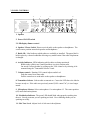
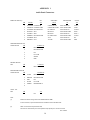
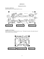
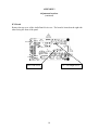
BEARS 1
AUDIO CONTROL SYSTEM
INSTRUCTION MANUAL
B1-0080
W. Savold
KØDKT 2/7/09
ACU instruction (B1-0080).doc
1
BEARS 1
AUDIO CONTROL SYSTEM
INSTRUCTION MANUAL
CONTENTS
Page
Section
1.0
2.0
3.0
4.0
5.0
6.0
7.0
8.0
9.0
Description
Specifications
Panel Controls
Rear Panel Interconnect
Set-up Considerations
Troubleshooting
Adjustments
Adapting to Other Radios
Block Diagram Description
3
4
5
7
8
9
10
11
13
Appendix 1
Audio Panel Connectors
16
Appendix 2
Adjustment Locations
17
Appendix 3
Adapter Cable Schematics
19
Appendix 4
Block Diagrams
29
2
BEARS 1
Audio Control System
1. DESCRIPTION The audio control system (ACS) was designed to meet the requirements of
the Brevard Emergency Amateur Radio Services, Inc. for the BEARS 1 vehicle. The system
allows all receiver and transceiver audio at a communications operating position to be monitored
through a single speaker or a headset. Seven audio inputs are provided and any combination
may be monitored. Each input has it’s own independent volume control. A sidetone monitor
with adjustable level control is available when using a headset. The ACS allows selection of one
of two microphones. A headset or desk microphone may be used and is selectable via a front
panel switch. Whichever microphone is being used along with push-to-talk (PTT) is switched to
the desired transceiver via the front panel selector. PTT may be accomplished using a foot
switch, hand switch or an integral microphone switch.
When the audio control panel is used at the Supervisor position, the composite outputs
(receive/transmit audio) from the other operating positions is input to the panel instead of the
individual radios. This allows the Supervisor to monitor the activities of the individual operation
positions. In addition to monitoring of the operating positions, three other radios/transceivers
including TV may be monitored.
An Intercom System (ICS) is included for communications between all operating positions and a
remote location (AUX) via the vehicles patch panel. The ICS is available only when using
headsets. Any position may signal any other position(s) using the call buttons. A blinking LED
and audible tone through the headset alerts the operator that he/she is being called. When in ICS
mode, the transmit audio and PTT is disabled. Receive audio, however, is still available in
addition to intercom audio in the headset. The microphone audio may also be routed to an
external PA system using the PA switch.
The Slideout J-Box located under Operating Position #1 includes ICS circuitry to combine and
route intercom signals to the various operating positions.
The Audio Control Panel has a dual digital clock for displaying local and UTC time
simultaneously. The clocks at all operating positions are synchronized to common time base.
The Audio Control Panel is housed in a 3.5 by 19 inch rack panel that is 5.5 inches deep. All
interface connections are via the rear panel. A remote headset / PTT J-box is mounted under
each operating position desk to keep cabling off the work area. Adaptation to the individual
radios of various models and manufacturers is accomplished using a custom interface cables.
3
2. SPECIFICATIONS
Receiver Inputs:
Inputs: 7 inputs are available and may be monitored simultaneously
Input Impedance: 8 Ohms
Single ended (negative ground)
Activity Monitors:
LED full bright: 190 mV in
Threshold: 115 mV in
High Pass Filter: -18dB down at 100 Hz.
Microphone Input:
Inputs: 2 inputs selectable by a front panel switch
Input Impedance: 10K Ohms (for Heil HC-5 microphone elements)
Level Monitor:
LED threshold: 3 mV microphone input (approx. 4.5 kHz dev)
Transceiver Outputs:
Outputs: 6 outputs with simultaneous audio
Low Z Capacitor coupled
250 mV out for 5 mV in
Noise Output: -40 dB below full output
Average output on voice: 100 mV RMS
PTT: Ground on PTT selectable by a front panel switch
Speaker Audio Power Output:
Output: 1.6 Watts into an internal 8 Ohms speaker
Headphone Output:
Combined receive audio, sidetone, and ICS audio as available
Output Level: Set to 200 mV across 30 ohms at 100 mV input
Size: 19” W x 3.5” H x 5.5” D
Power:
Standby: 385 mA @ 13.9 Vdc
Max Volume (voice) 700 mA @ 13.9 Vdc
Fuse: 2A Slow Blow – ¼” x 1 ¼”
ICS:
Headset only -- level adjustable
Full duplex
Selective calling of up to 6 stations
Remote power control to Slideout J-Box
PA Audio Output
Output Level: 100 mV RMS average on voice
Supervisor Output
Set to match input levels (100 mV in = 100mV out with volume control set to 9 o’clock)
4
3. PANEL CONTROLS
17
1
2
3
5
4
6
7
8
16
11
9
10
12
13
14
15
1. Speaker
2. Power ON/OFF switch
3. LED display dimmer control
4. Speaker / Phone Switch Directs received audio to the speaker or headphones. The
switch center position mutes both speaker and headphones.
5. Radio I.D. Label indicates which radios are available or installed. The paper label is
held in place by a slotted cardholder allowing easy modification if the radio complement
is changed.
6. Activity Indicators LEDs indicating which radios are being monitored.
Blinks at the syllabic rate if muted and there is activity on that radio.
On steady if selected either by pulling out the VOL control or by selecting it for
transmit using the "Transmitter Selector" knob.
7. Volume controls Rotating VOL control adjusts audio level.
Push the control in to mute radio
Pull the control out to send audio to the speaker or headphones.
8. Transmitter Selector Selects radio to transmit on. Causes the LED above the label to
become steady on. If the radio was previously muted (VOL control "in"), it is no longer
muted.
9. Microphone Selector Selects microphone #1 or microphone #2. The center position
(off) mutes both microphones.
10. Modulation Indicator The green LED should blink when properly speaking into
the mic. Steady on means you are speaking too loud. Never blinking means you are
speaking too softly.
11. Side Tone Level Adjusts level of side tone in head phones
5
12. ICS Volume Control and Activation Switch
Pull to activate the ICS system.
This disables the microphone from the transmitters. The system now operates in
full duplex mode via the headset.
Push the VOL control "in" to disable the ICS system and return to normal radio
operation.
While the ICS system is activated, the radio activity LED's continue to operate.
Radio audio is mixed with the ICS audio. Transmitting, however, is not possible.
Rotate the VOL control to adjust ICS audio to the headset.
While in ICS mode, the LED above the knob is illuminated.
13. ICS Alert LED blinks to indicate you are being called by another operating
position. A pulsating tone is sent to the headset. Activating the ICS causes the LED to
be steady on and mutes the tone. Deactivating the ICS system turns the LED off.
14. Public Address System Switch
Pull to route mic audio to the PA system.
Push to disconnect.
While in PA mode, the radio activity LED's continue to operate. Radio
audio is available in the headphones. Transmitting, however, is not
possible.
15. PA On Indicator The LED above the push button switch indicates the system is in
the PA mode.
16. Call Buttons Press the appropriate button(s) to call another operating position.
These are momentary contact pushbutton switches that latch a blinking alert LED at the
called position's panel.
17. Digital Clock
simultaneously.
The dual digital clock displays both local and UTC time
6
4. REAR PANEL INTERCONNECT
19
18
20
23
21
22
24
25
18. ICS connector to ICS J-box
J14 -- RJ-45 jack
19. Receive audio inputs from receivers/transceivers
J1 through J7 – RCA phono jacks – 8 ohm
20. Transmit audio and PTT output to transceivers
J8 through J13 – 6 pin DIN jacks
250 mV mic audio
Ground for PTT
21. Remote PTT input
J19 – RCA phono jack
Ground for PTT
22. AUX Audio
J15 – RJ-45 jack
Supervisor audio out
PA audio out
TV audio in
23. Supervisor audio input (used on supervisor panel only)
J16 – RJ-45 jack
Pos1, Pos2, Pos3, and Pos 4 audio
24/25. Microphone 1 and 2 inputs
J16 and J17 -- 6 pin DIN jacks
Mic audio
Headphone audio
PTT
26. Clock control
J20 – RJ-45 Jack
27. Fuse holder
2A Slow Blow fuse
7
26
27
28
28. 13.8 VDC input.
Pendant cable with Anderson Power Pole connector
5. SET-UP CONSIDERATIONS
It is important to set the volume control on the radios to the appropriate levels during initial setup. Setting them too high will cause considerable distortion within the system. The input
circuitry was designed to use audio from the speaker output jack with the volume control set to
comfortable listing level using the radio’s internal speaker. This normally occurs with the
radio’s volume control set to the 9 or 10 o’clock position. When properly set, the appropriate
activity LED on the ACS panel will blink on received voice peaks when the radio is NOT
selected (panel volume control pushed in and not selected for transmit). An easy way to set the
radio volume is to tune the radio to an unused channel and open the squelch. With the radio
NOT selected, increase the radio’s volume on noise until the activity LED just lights steady on.
The volume control on the radio can then be marked to easily return to this setting if
inadvertently moved.
8
6. TROUBLESHOOTING
If the Audio Control Panel seems to be malfunctioning, please check to be sure power is turned
on to the Operating Position, the Audio Control Panel, and the transceiver / receiver you wish to
use. If the Panel still does not work, try the following before reporting a malfunction.
PROBLEM
PROBABLE CAUSE
SOLUTION
At least 1 LED is not lit
Dim control turned
down
“Speaker” / “phones”
switch is in the center
off position
Rotate Dim control clockwise
Panel volume control
set too low or is not
selected
Select desired transceiver and set volume
control to 9 o’clock position
Transceiver volume
control is set too low
Transceiver volume
control is set too low
Set receiver/transceiver volume per
Section 5.
Set receiver/transceiver volume per
Section 5.
Transceiver volume set
too high
Set Receiver/transceiver volume per
Section 5.
Speaking too softly into
microphone
Speak up
Microphone selector
switch is in the center
off position
Select either “boom” or “headset” as
desired
System is in the ICS
mode
You are being called by
another operator
This is normal in the ICS mode. Push in
the ICS knob if mode is not desired
Pull ICS knob out to select ICS mode
A PTT switch is not
connected to the Jack
Panel
Plug in a PTT switch to one of the three
jacks available on the Jack Panel
The desired transceiver
is not selected
DC Power to operating
position 1 is not turned
on.
Select the desired transceiver with the
TRANSMIT selector switch
Turn on the DC power to operating
position 1. This powers the ICS J-Box.
No speaker or phones
audio
Activity LEDs do not
flicker with audio input
when transceiver /
receiver is NOT
selected
Audio is distorted
No Microphone audio
indicated on Mic Level
LED
ICS LED is blinking
and there is a pulsating
tone in the headphones
Pressing the PTT switch
does not key the
transmitter
The ICS system does
not work
Select “speaker” or “phones”
9
REF.
7. ADJUSTMENTS
There are relatively few adjustments within the Audio Control Unit; however, the following
adjustments are possible if at some time they are felt needed. Appendix 2 shows the location of
the adjustments on the circuit boards.
7.1 Speaker Output Level. The speaker output level is set by R22 on the Amp & P.S. Board.
This adjustment is set to maximum and may be reduced if desired. With the input set as
described in section 5 and the front panel volume control set to maximum the audio amplifier is
just beginning to clip. Any higher level will cause distortion.
7.2 Headphone Level. The headphone volume relative to the speaker volume level is
adjustable. During initial set-up, the headphone level is set to approximately 1/6 that of the
speaker output. R18 on the Audio Amp & P.S. board may be adjusted as desired.
7.3 Supervisor Audio Output level. The supervisor output level is set to 100 mV with a receive
input of 100 mV and the volume control on the front panel is set to the 9 O’clock position with
R15 on the Amp & P.S. board
7.4 Microphone Gain (individual). Two microphone amplifiers are used in the event that two
different types of microphone are to be used. The amplifiers are adjusted for the Heil HC-5
elements for both boom and headset microphones. If a different microphone type is to be used
by either input, R16 and R17 on the Transmit Audio board may be adjusted to accommodate
them.
7.5 Microphone Gain (overall). Initial microphone gain was set for 100 mV to the adapter
cables to give 3 kHz deviation out of the transceiver being controlled. If all radios seem to be
either too high or too low in deviation, R18 on the Transmit Audio board may be adjusted to
compensate.
7.6 ICS / PA Audio Output Level. The ICS / PA output level is set to 100 mV with a
microphone input level of 5 mV at 1 kHz using R13 on the ICS circuit board.
7.7 ICS Alert Tone Level. The alert tone level is set to maximum and may be reduced using
R10 on the ICS circuit board.
10
8. ADAPTING TO OTHER RADIOS
The Audio Panel is designed to accept single ended (one side grounded) audio from receivers
and provide transmit audio output at a level of 250 mV peak. Adapter cables are used to custom
tailor these signal levels to various radios used. Appendix 1 contains the schematics for the
adapter cables designed for the initial configuration of BEARS 1. The following describes the
considerations for adapting other radios to the Audio Panel.
Receive Audio
In most cases, adaptation of receive audio to the audio panel is simply a matter of connecting a
cable with a 1/8 inch phone plug on one end to the receivers external speaker jack and the other
end with an RCA plug connected to the audio panel.
In some cases, however, radios that are designed for high power audio output for driving a PA
system speaker cannot have one of the external speaker leads grounded. The radios of this type
typically have a DC voltage on the speaker leads of about 6 Volts. The circuit below is used in
these applications.
Transmit (microphone) Audio
The microphone output of the Audio Panel is at a relatively high level to accommodate legacy
radio equipment such as the Motorola Spectra and the E.F. Johnson Challenger. These radios
were designed for carbon microphones with very high output. When the panel is used with
more modern radios designed for dynamic or electret microphones, the output must be divided
down using a resistive divider. The resistive divider and any required coupling capacitor are
housed in the 6 pin DIN plug of the adapter cable. The Icom 706 required the use of a
transformer to eliminate a ground loop causing hum in the transmitted audio. Each radio must
be evaluated to design the adapter cable. The following steps must be taken.
1. Determine if there is voltage present on the microphone lead. If so, a coupling capacitor
must be used.
2. A resistive divider may now be designed to drop 100mV from the Audio Panel to the
voltage level required for 3 kHz deviation (60% mod for AM). The leg of the divider to
ground is 220 ohms. The figure below shows a simple way to determine the value of the
unknown resistor RX.
3. Key up the transceiver and adjust the variable resistor (RX) for a reading of 3 kHz deviation
on the Boonton 8210 (60% mod for an AM transceiver such as CB).
4. Measure the value of RX and construct the attenuator within the 6 pin DIN plug.
11
Attenuator Test Setup
The adapter cable schematics in Appendix 1 serve as examples of various cable designs.
12
9. BLOCK DIAGRAMS
Block diagrams of the Audio Control System elements are shown in Appendix 4. The following
is a basic description of some of the “blocks” that may or may not be obvious. Please refer to
the ACS Block Diagrams sheets A4-1 and A4-2 when reading the following.
A. Audio Amplifier: This is a Voltage gain of ten amplifier used to amplify the audio level
from the external speaker jack of the receiver/transceiver to a relatively high level for
switching. This amplification also gets the audio to a level that can be detected by the
Activity Monitor (B).
B. Activity Monitor: The Activity Monitor is a voltage doubling rectifier with a transistor LED
driver. The time constant of the rectifier is such that it responds to voice peaks and valleys.
The blinking LED indicates activity on the channel if that channel is not selected. The
Selection Logic (C) forces the LED on continuously if it is selected under some conditions.
C. Selection Logic: The Selection Logic is used to control the analog switch that enables the
receive channel and the state of the LED activity monitor. If the transceiver is selected by
the “TRANSMIT” switch, the receive audio channel is forced on and the LED glows
constant on. If the transceiver channel is not selected for transmit but is selected for
monitoring by pulling out on the volume control knob, the receive channel is also forced on
as long as Push-to-talk (PTT) is not activated. Under this condition, LED activity monitor
glows constant on. During PTT, the receive channel switch is forced off and the LED returns
to normal activity monitoring.
D. Summing Amplifier: The summing amplifier sums all of the selected receive channels (up
to 7). The output of the summing amplifier feeds the “mute” switch and the speaker and
headphone amplifiers as well as the Supervisor Audio output amplifier. Separate amplifiers
are used for these functions because they combine different signals.
Following the
summing amplifier, a high pass filter is implemented providing 18+ dBs of attenuation at
100 Hz. This filter reduces the level of output tones from some repeaters that can become
irritating when using a headset.
E. Microphone Amplifiers: Two low noise microphone amplifiers are used to accommodate
two different types of microphones if desired. In the initial configuration these two
amplifiers are identical and designed for use with Heil HC-5 microphone elements. The
amplifier is set to a Voltage gain of 200 with an input impedance of 10K. One is used for
the Boom mic and the other is for the headset mic and selected by a front panel switch. The
output of these amplifiers drives the 6 microphone output amplifiers and the sidetone level
control through the PTT switch. The ICS audio is enabled by the ICS control and not
subject to PTT. This allows more telephone like operation in ICS mode
F. Microphone Level Monitor: The microphone level monitor operates like the receive activity
monitors (B). In this case, however, the circuitry is used to indicate to the operator whether
he or she is speaking too softly or too loud. This monitor is only active in transmit modes
and not in ICS mode.
13
G. Supervisor Audio Output: The Supervisor Audio Amplifier combines receive audio with
transmit audio. Transmit audio is derived from sidetone. The level of both signals is set by
the operator for comfortable listening. The amplifier also drives the 100 Ohm Cat 5E cable
to the supervisors panel.
H. Transmit Audio Out: Six buffer amplifiers are used to drive and isolate the microphone
adapters for the various transceivers used. The audio out of these amplifiers is active all the
time and identical. They are not switched with the TRANSMIT switch. Since the outputs of
these amplifiers are biased at +5 Vdc, a coupling capacitor is used to block this voltage.
I. Microphone Logic: The microphone logic routes PTT to the selected transceiver. A ground
is sent to the transceiver selected by TRANSMIT upon PTT.
J. PTT Logic: The PTT Logic block is used to generate discretes needed by the other circuitry.
PTT is inhibited when ICS mode is selected. The PULL discrete is a ground signal to the
Receive Select pull switches that is released on PTT. This signal is sent to Selection Logic
(C). Three isolated PTT inputs are provided.
K. Power Supply: The power supply consists of an input filter, a 10 Vdc regulator and the LED
dimmer circuitry. The input filter is simply a reverse voltage protection diode and a 24V
surge protector diode. The 10 Vdc regulator supplies the DC power for the other circuits in
the Audio Control Unit. The one exception is the ICS circuitry which has it’s own regulator
to handle the power required by the ICS and PA amplifier/drivers.
L. ICS Circuitry. The ICS circuitry includes the ICS circuit board within the Audio Control
Unit and that in the Slideout J-Box (called the ICS J-Box here after). The block diagram of
this function is shown on ACS Block Diagram sheet A4-2.
L1. Call Button Encoder: The call button encoder on the ICS circuit board converts the 6
pushbutton discretes to 3 wire BCD. This is done to reduce wire count between the Audio
Control Unit and the ICS J-Box. The three wires also provide signals to apply power to the Jbox.
L2. Latch & Alert Logic: When the position this ACU is in is being called by another position,
a ground discrete from the ICS J-Box sets a latch in the ACU. The output of the latch enables
the ICS LED blinker and alert tone generator. The LED continuers to blink and a pulsating alert
tone is sent to the headset until the operator acknowledges the call by pulling out on the ICS
knob. At this point, the latch is reset and the alert tone is turned off. The ICS LED becomes
steady on indicating that the ACU is now in ICS mode. The logic sends an “ICS / PA select”
discrete to PTT Logic (J) to inhibit radio transmissions.
L3. ICS / PA Output Amplifier: The ICS / PA output amplifier takes in microphone audio(E)
and sends it to ICS J-box for distribution to other positions if in the ICS mode or the PA system
if selected. The amplifier drives the 100 Ohm Cat 5E cable to the ICS J-Box or PA system.
L4. Power Switch Logic: Since there is no power switch on the Slideout / ICS J-Box, the 3
wire BCD discretes are used to signal the J-Box that another position is powered up and causes
itself to power up. Current flowing in one or more of the 3 wires is enough to cause a power
relay in the J-Box to energize.
14
L5. Call Decoder: The Call Decoder takes in the 3 wire BCD discretes from the 6 ACU’s and
converts them back into decimal (6) call discretes. The call discretes are wired to the
appropriate panels to signal that they are being called.
L6. ICS Summing Amplifier: The ICS Summing Amplifier takes in the audio from up to 6
other operating positions and sends the summed output back to the positions. The amplifier is
required to drive the 6 100 Ohm Cat 5E cables back to the ACP’s at the operating positions.
M. RF Filters. RF filters are used on all inputs and outputs to keep RF out of the audio circuits.
LC and RC filters are used providing over 30 dBs of attenuation to HF frequencies and above.
15
APPENDIX 1
Audio Panel Connectors
MODULAR JACKS (1)
PIN
COLOR
ICS
AUX AUDIO
SUPERVISOR
J14
J15 (2)
JI6
WHT/ORG ICS AUDIO IN
S-AUDIO OUT HI
POS 1 AUDIO HI
LOAD +
2
ORG/WHT ICS AUDIO COM
S-AUDIO OUT COM
POS 1 AUDIO COM
LOAD -
3
WHT/GRN MIC AUDIO OUT
PA AUDIO HI
POS 2 AUDIO HI
CLOCK +
4
BLU/WHT
SIG 1
REC #6 LO
POS 3 AUDIO COM
DATA -
5
WHT/BLU
SIG2
REC #6 HI
POS 3 AUDIO HI
DATA +
6
GRN/WHT MIC AUDIO COM
PA AUDIO COM
POS 2 AUDIO COM
CLOCK -
7
WHT/BRN SIG 4
TV HI
POS 4 AUDIO HI
N.C.
8
BRN/WHT CALL
TV COM
POS 4 AUDIO COM
GND
J8 THRU J13
PIN
1
MIC AUDIO HI
2
MIC AUDIO COM
3
PTT
4
PTT COM
5
SPARE
6
GND
RECEIVE INPUTS
RCA
J1 THRU J7
PIN
1
REC AUDIO HI
MICROPHONE AUDIO IN
CIRCULAR DIN
J17 AND J18
PIN
1
WHITE
MIC AUDIO HI
2
BROWN
MIC AUDIO COM
3
RED
PTT
4
BLACK
PTT COM
5
GREEN
HEADPHONE HI
6
LOCAL PTT
RCA
PIN
1
J19
PTT
Note:
(1)
Modular connector wiring conforms to standard EIA/TIA 568B.
In this convention, Tip is the white/color wire and Sleeve is the color/white wire.
(2)
J20
1
TRANSCEIVER OUTPUTS
CIRCULAR DIN
CLOCK
When J15 is used in a Supervisors Panel,
a Scanner is connected to pins 4 and 5 (Receive input 6) and pins 1 & 2 are not used.
Rev 4/12/06
16
APPENDIX 2
Adjustment locations
Transmit Audio Board
Remove bottom cover of Audio Panel for access.
Boom Mic Gain
Headset Mic Gain
Master Mic Gain
Amplifier & P.S. Board
Remove bottom cover of Audio Panel for access. This board is located on the right side panel
when facing the front of the panel.
Headphone Level
Supervisor Audio Level
17
Speaker Level
APPENDIX 2
Adjustment locations
(continued)
ICS Board
Remove the top cover of the Audio Panel for Access. The board is located on the right side
when facing the front of the panel.
Alert Tone Level
ICS / PA Output Level
18
APPENDIX 3
ADAPTER CABLE SCHEMATICS
Adapter
Page
Yaesu FT-8800
20
Icom 706
21
EF Johnson Challenger
22
Relm RMU 45
23
Motorola Spectra
24
Cobra CB
25
MA/Com EDACS
26
Boom Microphone Cable
27
Jack Panel Cable
28
19
20
21
22
23
24
25
26
27
28
APPENDIX 4
Block Diagrams
29
APPENDIX 4
Block Diagrams
30
NOTES:
31