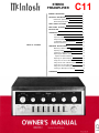
1
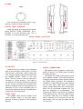
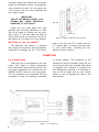
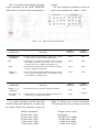
STEREO
PREAMPLIFIER
C11
GENERAL DESCRIPTION
1
TECHNICAL DESCRIPTION
Mechanical Specifications
1
2
Electrical Specifications
TABLE OF CONTENTS
2
FRONT PANEL FACILITIES
2
BACK PANEL FACILITIES
5
INSTALLATION
6
CONNECTING
8
A-C Connections
Input Connections
Output Connections
Loudspeaker Phasing Connections
Ground Connection
OPERATING INSTRUCTIONS
Balancing a Stereo System
Adjusting Phase
Listening to a Stereo Record
Adjusting the Balance Control After the
System has been Balanced
Adjusting for Special Effects
Using the C11 with a Stereo Tuner
Using the C11 with a Stereo Tape Machine_
Using the C11 with Tape Deck
Using the C11 with Microphones for Stereo.
Listening to Monophonic Records
GUARANTEE
8
9
10
11
11
11
11
12
12
12
12
13
13
13
13
13
16
C11 STEREOPHONIC PREAMPLIFIER
GENERAL
The Mcintosh C11 Stereophonic Preamplifier is a control center for any stereophonic sound system. To increase the
enjoyment of stereo, this control center does
four jobs with precise control.
First, the control center amplifies weak
electrical impulses. As the record rotates on
the turntable, undulations in the grooves
move the pick-up stylus approximately onethousandth of an inch, in any direction, from
the rest position. From this slight mechanical
movement, the pick-up stylus generates a
weak electrical impulse on the order of a few
thousandths of a volt. To amplify and preserve the information in such an electrical
impulse, the finest amplifier performance is
required.
Second, every sound system is used in a
different acoustical environment. The tone
balance of the music is affected by variations
DESCRIPTION
in environment. Also, people listening to the
music have varying ideas of correct tone balance. To compensate for these conditions, a
high-quality control center is needed.
Third, there is a great variety of stereophonic and monophonic records manufactured today, both domestic and foreign. The
control center must accurately compensate
for the equalization introduced in the recording process.
Fourth, with programs originating from
several sources such as tuners, records, tape
machines, microphones, etc., a control center is needed to select and switch these
sources separately or in combination.
All of these jobs are performed with excellence by the C11 and yet this instrument
is simple to operate, easy to mount, and is
the finest in appearance.
TECHNICAL DESCRIPTION
The C11 Stereophonic Preamplifier combines excellence in performance with ease of
operation. The controls used the most have
large diameter knobs. A new type of rocker
switch indicates those controls with simple
off-on functions. The C11 has an illuminated
front panel with light intensity control to
provide convenient reading under low-level
lighting conditions.
The C11 circuit consists of three amplifying sections in duplicate for the left and right
stereo channels and a power supply. The
first section is the input preamplifier used to
amplify and equalize the input signals coming from phonograph pickups, microphones,
or tape heads. Skillful layout, grounding, and
shielding for low hum pickups, metal film and
wire wound resistors, terminal boards with
high specific resistivity, low noise tubes and
extreme care in manufacturing combine to
achieve a new low in noise and hum.
The second amplifying section follows the
volume control, and thus it is impossible to
overload the circuit or any following circuits.
The same techniques as were used in the
preamplifier stage assure low hum and noise.
The bass and treble tone controls are feedback type circuits and operate in connection
with this section. Exceedingly low distortion
and correct frequency response are assured
using this arrangement.
The third section is the cathode follower
output. The sharp cut-off (18db per octave)
rumble and high frequency filters are associated with this section. Output level set controls are located at the input of the cathode
follower to allow simple balance of the entire
amplifying and speaker system. These controls are conveniently accessible at each side
of the front panel under the end caps.
The power supply deserves special mention. The power transformer is constructed
with "core" type grain oriented laminations
and magnetic shielding for low hum field.
Long life rectifiers, full wave rectification,
filter condenser sectionalizing and careful
grounding add to the hum free and long life
characteristics of the C11.
Special attention has been given to the
mechanical design also. The C11 may conveniently be installed in furniture cabinets,
custom built installations, or professional
relay racks. The tubes and the electrical connections are conveniently located on the
back panel of the C11 for ready access.
1
MECHANICAL
Dimensions
Chassis: 14½ inches wide; 4¾ inches high;
12 inches deep including connectors.
Front Panel: 15¾ inches wide; 51/8 inches
high
Front Panel Mounting Space Required: 16 3 / 8
inches wide; 5¼ inches high
SPECIFICATIONS
Weight
Chassis: 15 pounds
Shipping Weight: 25 pounds
Finish
Anodized gold and black (front panel)
ELECTRICAL SPECIFICATIONS
Main Output
2.5 volts with rated input
2 output jacks in parallel for each channel
Power Requirements
117 volts, ac, 50/60 cycles, 30 watts
Input Sensitivity and Input Impedance
Auxiliary: 0.25 volt; 250,000 ohms
Tape: 0.25 volt; 250,000 ohms
Tuner 1: 0.25 volt; 250,000 ohms
Tuner 2: 0.25 volt; 250,000 ohms
Phono 1: 2 millivolts; 47,000 ohms
Phono 2: Same as phono 1
Tape Head: 2 millivolts; 1 megohm
Tape Compare (Monitor): 0.25 volt; 250,000
ohms
Microphone: 2.5 millivolts; 1 megohm
Tape Output
0.25 volt with rated input
1 output jack for each channel
Left Plus Right Output
1 volt from generator impedance of 25,000
ohms
Distortion
Less than 0.2% at rated output, 20 to 20,000
cycles
Voltage Amplification
Low-level inputs to Main Output: 1,000 to 1
(60db) at 1000 cycles
Low-level inputs to Tape Output: 100 to 1
(40 db) at 1000 cycles
High-level inputs to Main Output: 10 to 1
(20 db)
High-level inputs to TapeOutput: 1 to 1 (0 db)
Tape Compare (Monitor) input to
Main Output: 10 to 1 (20 db)
Hum and Noise
High-level inputs: 85 db below rated output
Low-level inputs: less than 2 microvolts at
input terminals
A-C Auxiliary Outlets
1 unswitched for tape machine or turntable,
colored Red
4 switched, colored Black
Frequency Response
± 0.5 db; 20 to 20,000 cycles
FRONT PANEL FACILITIES
Figure 1. C11 Front Panel
2
INPUT SELECTOR
INPUT SELECTOR
TUNER 2
PHONO 1
TUNER 1
PHONO 2
TAPE
MIC
AUX
TAPE HD
Select any one of eight program sources
with this switch:
1. AUX: any auxiliary service requiring flat
amplification, such as a television set, is
connected to the C11 through this position.
2. TAPE: any self-contained tape machine
(tape machine having its own playback
preamplifier) is connected to the C11
through this position.
3. TUNER 1: AM and FM outputs from a
stereo tuner or MPX FM program are connected to the C11 through this position.
4. TUNER 2: same as TUNER 1.
5. PHONO 1: connects the C11 for stereo
and monophonic operation for records.
6. PHONO 2: same as PHONO 1.
Listen thru both loudspeakers to either
track of a stereo program source.
Turn the MODE SELECTOR to:
1. L TO L & R: connects the " l e f t " input to
both loudspeakers.
2. R TO L & R: connects the "right" input to
both loudspeakers.
3. STEREO REV: connects the "left" input to
the "right" loudspeaker and the " r i g h t "
input to the "left" loudspeaker.
4. STEREO: connects the " l e f t " input to the
" l e f t " loudspeaker and the " r i g h t " input
to the "right" loudspeaker.
5. MONO (L+R): adds the " l e f t " input and
the "right" input and then connects the
L+R program to both amplifiers and loudspeakers.
6. L+R TO L: connects the "left plus right"
programs to the "left" loudspeaker only.
7. L+R TO R: connects the "left plus right"
programs to the "right" loudspeaker only.
BASS CONTROLS
BASS CONTROLS
LEFT
0
RIGHT
0
7. MIC: stereo microphones are connected
to the C11 through this position.
8. TAPE HD: a tape deck that does not contain its own playback preamplifier is connected to the C11 through this position.
MODE SELECTOR
MODE SELECTOR
STEREO REV
STEREO
MONO (L+R)
R TO L&R
L+R TO L
L TO L&R
L+R TO R
The LEFT and RIGHT BASS CONTROLS
regulate bass loudness to the left and right
speakers, respectively. Clockwise rotation increases bass loudness; counterclockwise
rotation decreases bass loudness.
TREBLE CONTROLS
TREBLE CONTROLS
Use the MODE SELECTOR to:
Listen to normal stereo (4 following and
page 16).
Reverse the left and right arrangement of
musical instruments (3 following and page
12).
Balance the amplifiers and loudspeakers
in a stereo system (6 and 7 following and
page 11).
Listen to monphonic sound (1 and 2
following and page 13).
LEFT
0
RIGHT
0
The LEFT and RIGHT TREBLE CONTROLS
regulate treble loudness to the left and right
speakers, respectively. Clockwise rotation
increases treble loudness; counterclockwise
rotation decreases treble loudness.
3
BALANCE
BALANCE
0
LEFT
RIGHT
This two-positioned switch reverses the
phase in the left channel to correct for loudspeaker or program phasing.
POWER
POWER
ON
The C11 is balanced for unequal program
sources by this control.
LEFT . . . turning the control to the left accents the left channel by reducing the right
channel output.
RIGHT . . . turning the control to the right accents the right channel by reducing the
left channel output.
OFF
The C11 and the four black receptacles on
the back panel are turned on by this switch.
RUMBLE
RUMBLE
COMPENSATOR
FLAT
COMPENSATOR
RIAA
FILTER
LP
This control corrects for program equalization introduced by the recording process.
TAPE
TAPE
NORMAL
Low-frequency rumble noise below 50cps
created by a turntable or record changer and
acoustically coupled feedback are reduced
when the RUMBLE filter button is pushed to
the FILTER position.
H.F.
H.F.
FLAT
MONITOR
This control makes it possible to instantaneously compare the recorded material
with the source signal. Tape jacks on the back
panel accept a signal from a tape recorder
with a monitor head and preamplifier.
NORMAL . . . the program source is fed
through the power amplifiers and the loudspeakers.
MONITOR . . . the signal source becomes the
monitored program from the recorded tape
and is fed through the power amplifiers and
loudspeakers.
FILTER
This switch minimizes surface noise when
reproducing old, badly worn recordings. Its
positions are:
FLAT . . . filter disconnected.
FILTER . . . rolls off response sharply at 5KC.
LOUDNESS
LOUDNESS
NORMAL
PHASE
PHASE
NORMAL
REVERSE
4
COMPENSATED
This switch converts the VOLUME control
to a loudness compensated control when in
the COMPENSATED position.
VOLUME
VOLUME
This continuously variable control regulates the volume for both channels.
OUTPUT LEVEL CONTROLS
Under the panel end caps are the thumb
wheel OUTPUT LEVEL CONTROLS. The L
OUTPUT is on the left-hand side. The R
OUTPUT is on the right-hand side.
BACK PANEL FACILITIES
Figure 2. C11 Back Panel
AC OUTLETS
OUTPUT CONNECTIONS
There are five AC outlets on the left-hand
side of the rear panel. (See Figure 2.) These
outlets have a maximum rating of 660 watt
total. The four black outlets are controlled by
the POWER ON-OFF switch on the front
panel. The red outlet is used for powering a
turntable or record changer. This outlet is
not switched so that the turntable power will
not be turned off while the turntable idler
wheel is engaged. With this arrangement it is
necessary to turn off the turntable with its
own control switch so that the turntable drive
system will not be damaged.
The MAIN output connects to power amplifiers (Figure 2); the TAPE output connects
to a tape recorder.
PANEL LIGHT
The PANEL LIGHT switch, located in the
lower left-hand corner of the back panel,
provides a choice of bright or dim front panel
lighting.
The MAIN and TAPE output jacks are fed
from cathode followers. The input impedance
of devices connected to these outputs should
be 50,000 ohms or greater. The capacitive
reactance of connecting audio cables should
not be less than 8,000 ohms at 20,000
cycles. Longer cables than are normally supplied can be connected between the C11
and the amplifiers or loudspeakers. The
length of the cable is limited by the capacity
of the cable per foot. The total capacity must
not exceed 1000 mmf. For instance; cables
with a capacity of 25 mmf per foot may be
40 feet long; 13.5 mmf per foot cable may be
75 feet long.
5
HIGH LEVEL INPUTS
These receptacles accept high-level program source connections as follows:
TAPE MONITOR (COMPARE) . . . accepts a
signal from a tape recorder with a monitor
head and preamplifier.
AUX . . . accepts any auxiliary service requiring flat frequency response, such as a
T.V. set, tuner, tape recorder with its own
playback preamplifier, etc.
TAPE . . . accepts connection from a tape
machine with its own playback preamplifier.
TUNER 1 & TUNER 2 . . . accept AM and FM
outputs from a stereo tuner or a pair of
stereo tuners.
LOW LEVEL INPUTS
These receptacles accept low-level program source connections as follows:
PHONO 1 & 2 . . . accepts connection for
normal stereo and normal monophonic
operation.
MIC . . . accepts connection from stereo
microphones.
TAPE HEAD . . . accepts connection from a
The C11 can be installed in conventional
furniture cabinets, custom built installations
or professional relay racks. If the unit is to
be placed on a shelf or table-top, it is recommended that it be housed in a Mcintosh L66
cabinet. Install the C11 from the front of the
cabinet, not from the rear.
To support the weight of the C11, the
wood panel used to mount it, should be at
least ¼ inch thick. If the front panel of a cabinet is made of wood, a shelf may be needed
to support the rear of the chassis to prevent
tape deck that does not contain its own
playback preamplifier.
TAPE EQUALIZATION
On the back panel there are two tape
equalizing controls. These controls should be
set to NAB for normal 7.5 inch tape speed
machines. Turning the TAPE EQUALIZATION
controls clockwise increases the treble response, turning it counterclockwise decreases the treble response. Use the controls
to compensate for 3% tape speed for individual tape head characteristics.
LOUDSPEAKER PHASING CONNECTIONS
Two pairs of screw terminals are located
on the lower left section of the C11 back
panel. The speaker leads from the " l e f t "
power amplifier should be connected to the
screw terminals marked FROM AMPLIFIER.
The pair of terminals marked TO SPEAKER
should be connected to the " l e f t " loudspeaker.
These connections allow the front panel
PHASE switch to reverse the phase on the
left loudspeaker. This arrangement is convenient when setting up a stereo system.
warping. When the C11 is mounted on a
metal rack panel, a shelf is not needed.
The C11 installation should allow 12
inches behind the front panel so that there
is at least 1½ inches for connectors. The desirable width and height are 16½ inches and
5½ inches, respectively, so that sufficient
space is allowed for the circulation of air.
These are inside dimensions. The front panel
mounting space width and height are 16 3 / 8
inches and 5 3 / 8 inches, respectively.
Positions "A" to " C " show the location of the
vertical center line, the use of the measuring
tool (mounting strip) to locate the horizontal
center line, and how to measure off the two
points to the right and left of the vertical
center line.
Figure 3. Cutout Measurements
6
MAKING THE FRONT PANEL CUTOUT
The panel is cut out using the "FRONT
PANEL CUTOUT TEMPLATE." To position
the template on the front of the panel, make
two locating holes from the back (inside) of
the panel using one of the mounting strips
(½ inch by 3½ inches) as a measuring tool.
Proceed as follows:
Scribe a vertical center line through the
exact center of the proposed cutout area
from the top of the panel to the top surface
of the shelf as illustrated in " A , " Figure 3.
Using one of the mounting strips as a measuring tool, draw a horizontal line 3½ inches
above the shelf. (See " B , " Figure 3.) Place a
mounting strip along the horizontal line to the
left of the vertical center line and mark a
point 3½ inches left from the vertical center
line. Repeat this procedure and mark a point
3½ inches to the right of the vertical center
line. These points should now be 3½ inches
up from the top of the shelf and 7 inches
apart, one 3½ inches to the left and one
3½ inches to the right of the vertical center
line. (See " C , " Figure 3.) Drill a 3/16 inch hole
at each point. Hold the drill perpendicular to
the front panel so that the hole will be located
accurately on the front of the panel.
inch or 3/8 inch shelf.) Remove the four plastic
feet from the bottom of the C11.
In the mounting hardware package are
four 6-32 flathead screws and eight 6-32
roundhead screws. Two of the flathead
screws of the proper length are used to attach the mounting strips to the cabinet. Four
of the roundhead screws of the proper length
are used to attach the C11 to the cabinet and
mounting strips. The 6-32 x ½ inch screws
are to be used with panels ½ inch to 1 inch
in thickness.
Select the proper length 6-32 flathead
screws and use them to install the two mounting strips behind the front panel. Be sure
that the edge of the strip with the clips is
toward the panel opening. Line up the mounting strips on each side of the front panel
cutout so the three holes in the strip are in
line with the three holes in the panel. (See
Figure 4.) Install the proper length flathead
screws in the center hole of each strip. Drive
them in so the flatheads are flush with the
panel; if necessary, countersink the two
center holes.
Position the template on the front of the
panel using the two locating holes to line it
up correctly. Scribe the rectangular opening
on the front panel and mark the position of
the six mounting holes. Drill the six 3/16 inch
mounting holes before cutting the panel
opening. Then cut out the opening. It is important that the cutout be just with in the lines.
SHELF MOUNTING
If the installation requires a shelf, proceed
as follows: Locate the center of the shelf and
scribe a line from front to back. The "SHELF
CUTOUT PLATE" is marked for panel thicknesses from ¼ inch to 1 inch. Fold the template on the line that corresponds to the
thickness of the panel. Place it on the shelf
so that it butts against the inside of the panel.
Match the center line mark on the template
to the scribed center line on the shelf. Mark
the position of the four drill holes. Drill the
four ¼ inch holes.
INSTALLING THE C11
Remove the four screws holding the C11
to the shipping pallet. (Save these screws,
you will need them if your cabinet has a ¼
Figure 4. Securing the Mounting Strip to the Front Panel
Carefully insert the C11 through the front
of the panel opening so that it rests on the
shelf. Insert the proper length 6-32 roundhead screws into the four holes in the mounting flanges on each end of the tuner front
panel. Drive them in, but do not tighten.
If the cabinet is fixed and will not be
moved about, it is not necessary to secure
the C11 chassis to the shelf. If the cabinet is
to be moved about, it is recommended that
the C11 chassis be secured to the shelf. The
four 10-32 x ½ inch screws used in shipping
are supplied for use if the shelf is under 3/8
inch. Use the 10-32 x ¾ inch screws if this
shelf is V2 inch or 5/8 inch thick and the 10-32
x 1 inch screws if the shelf is ¾ inch or 7/8
7
inch thick. Secure the chassis with the proper
length 10-32 machine screws, inserting them
from beneath the shelf. Do not tighten the
10-32 screws until you have tightened the
front panel screws.
IMPORTANT:
USE OF THE WRONG LENGTH 10-32
SCREWS MAY CAUSE ELECTRICAL
SHORTING IN THE CIRCUIT.
END CAP
Attach the two metal panel end caps
(packed with mounting hardware) on each
end of the panel by sliding onto the pins.
(See Figure 5.) The end caps are held by
spring tension and can easily be removed if
the chassis is to be taken out of the cabinet.
MOUNTING IN THE L66 CABINET
The Mcintosh L66 cabinet is supplied
with complete instructions and all necessary
hardware for installing the C11. The dimen-
PUSH ON
Figure 5. Fitting of Panel End Caps to Panel
sions of the L66 are 169/16 inches wide by
6 11 / 16 inches high, including mounting feet,
by 13¾ inches deep, including the front
panel and control knobs.
CONNECTING
A-C CONNECTIONS
There are five a-c receptacles on the rear
panel. (See Figure 6.) These receptacles
have a maximum rating of 660-watt total. The
four black receptacles are controlled by the
POWER ON-OFF switch on the front panel.
The red receptacle is not switched. The red
receptacle is used for powering a turntable
or record changer. The receptacle is not
switched so that the turntable power will not
be turned off while the turntable idler wheel
is engaged. The turntable is protected by
this arrangement because it is necessary to
turn off the turntable with its own control
switch so that no damage will result to the
drive system.
Figure 6. A-C Connections
8
The C11 provides eight separate program
inputs controlled by the INPUT SELECTOR
switch and one input for tape comparison or
monitor.
The input program connection should be
made in accordance with Tables 1 and 2.
Figure 7. C11 Input Connections (Back Panel)
INPUT
SENSITIVITY
INPUT
IMPEDANCE
The tape monitor input accepts a signal from a tape
recorder with a monitor head and preamplifier.
0.25 V
250K
AUX
The auxiliary input accepts any auxiliary service requiring
flat frequency response, such as a T.V. set, tuner, tape
recorder with its own playback preamplifier, etc.
0.25 V
250K
TAPE
The tape input operates with tape machines containing
their own playback preamplifier.
0.25 V
250K
TUNER 1 &
TUNER 2
The tuner inputs accept AM and FM outputs from a stereo
tuner or a pair of stereo tuners or the multiplex output
of an adapter or multiplex tuner.
0.25 V
250K
INPUT
SENSITIVITY
INPUT
IMPEDANCE
CONNECTION
FUNCTION
TAPE MONITOR
(COMPARE)
CONNECTION
FUNCTION
PHONO 1 & 2
MAGNETIC
These jacks are to be used with magnetic cartridges.
2 MV
TAPE HEAD 1 &2
2-10 MV
These jacks are to be used with a tape deck that does not
contain its own playback preamplifier.
2 MV
If a phono cartridge requires less than
47,000 ohms load impedance, a resistor can
be added across the terminals of the car-
Resistor Across Input
47,000
37,000
27,000
15,000
6,800
No Resistor
180,000 ohms
62,000 ohms
22,000 ohms
8,200 ohms
(47K)
(37K)
(27K)
(15K)
(6.8K)
1 megohm
tridge to achieve the correct termination.
The following chart may be used as a guide:
Desired Impedance
ohms
ohms
ohms
ohms
ohms
47 K
(180K)
(62K)
(22K)
(8.2K)
9
Figure 8. Turntables Feeding Low Level Input
OUTPUT CONNECTIONS
Two sets of outputs, located in the upper
left-hand corner of the back panel, are provided. (See Figure 2.)
The MAIN output connects to power amplifiers (Figure 9) and the TAPE output to
feed a tape recorder.
The MAIN and TAPE output jacks are fed
from cathode followers. The input impedance
of devices connected to these outputs should
be 50,000 ohms or greater, and the capacitive reactance of audio cables connecting
these devices should not be less than 8,000
ohms at 20,000 cycles. This is the reactance
of a capacity of 1,000 mmf. Audio cable
having a capacity of 25 mmf per foot may be
40 feet long; 13.5 mmf per foot cable may be
75 feet long.
The tape output is affected only by the
INPUT SELECTOR in the AUX, TAPE, TUNER
1, TUNER, or MIC positions.
When the INPUT SELECTOR is turned to
PHONO 1 or PHONO 2 inputs then the record
compensator is included. When the INPUT
SELECTOR is turned to TAPE HD then the
record compensator switch should be set at
RIAA.
On the back panel there are two TAPE
EQUALIZATION controls. These controls
should be set to NAB for normal 7.5 inch tape
speed machines. Turning the TAPE EQUALIZATION controls clockwise increases the
Figure 9. MAIN Output Connected to Power Amplifiers
10
treble response, turning it counterclockwise
decreases the treble response. Use the controls to compensate for 3% tape speed for
individual tape head characteristics.
A left plus right output jack is next to the
MAIN output. It is marked L+R. A monophonic signal can be distributed to other
rooms by connecting a third power amplifier
to the jack marked L+R. This amplifier is
used to drive the monophonic loudspeakers.
The cable connecting to this output should
not have a capacity of more than 200 mmf.
The input impedance of the power amplifier
connecting to this output should not be less
than 150,000 ohms (150K). The generator
impedance at this output is approximately
25,000 ohms (25K).
LOUDSPEAKER PHASING CONNECTIONS
Two pairs of screw terminals are located
on the lower left section of the C11 back
panel. The speaker leads from the " l e f t "
power amplifier should be connected to the
screw terminals marked FROM AMPLIFIER.
The pair of terminals marked TO SPEAKER
OPERATING
BALANCING A STEREO SYSTEM
The ultimate in stereo performance and
listening enjoyment is obtained through the
proper balancing of the stereo system. A
properly balanced stereo system must be in
phase. Each channel must be equal in loudness and similar in frequency response.
Do not use the C11 BALANCE control for
this procedure. The C11 BALANCE control
is used to adjust for any unbalance in the
source material, the phono cartridge, and
tape machine.
Before attempting the balancing of the
C11 make sure the controls on the amplifiers
are set properly. On the MC240 and MC275
turn the control marked BALANCE to its
center position. On the MC225 set the input
level controls for each channel to the black
dot above the control.
To properly balance the C11, proceed as
follows: A familiar recording, either stereophonic or monophonic, should be used in
balancing the C11.
1. Turn the INPUT SELECTOR to the position corresponding to the program selected.
2. Turn the BASS CONTROLS and TREBLE
CONTROLS to their 0 positions.
should be connected to the " l e f t " loudspeaker.
These connections allow the front panel
PHASE switch to reverse the phase on the
left loudspeaker. This arrangement is convenient when setting up a stereo system.
GROUND CONNECTION
A single ground post is provided. The
chassis ground from turntable, record changers (motors used with each), tape decks, etc.,
should be returned to this post. Do not duplicate this ground circuit. Hum is likely to be
heard in the system if duplicate ground returns are used.
The left and right program cables from
each source should be twisted together and
the ground wire from each source can be
wound or twisted in with these cables. To
avoid hum, make sure the ground wire does
not make any connections to shields of the
left and right channel cables except for the
connection provided with the C11 ground
post.
INSTRUCTIONS
3. Turn the MODE SELECTOR to the L+R
TO L position.
4. Place the COMPENSATOR switch in the
RIAA position.
5. Place the TAPE switch in the NORMAL
position.
6. Place the PHASE switch in the NORMAL
position.
7. Place the POWER switch in the ON
position.
8. Place the RUMBLE switch in the FLAT
position.
9. Place the H.F. cutoff filter switch in the
FLAT position.
10. Place the LOUDNESS switch in the
NORMAL position.
11. Turn the BALANCE control to the 0
position.
12. While the program is playing, alternate
the MODE SELECTOR between the L+R TO
L position and the L+R TO R position. Adjust
the thumb wheel level controls under the
end caps until the loudspeakers are of equal
loudness.
When the proper balancing of the Mcintosh C11 is accomplished, the stereo system
will remain balanced throughout all modes
of operation.
11
ADJUSTING PHASE
1. Place the COMPENSATOR switch in the
RIAA position.
2. Set the MODE SELECTOR to STEREO.
3. Turn the BASS CONTROLS and TREBLE
CONTROLS to 0.
Stand approximately 10 feet in front of
and midway between the loudspeakers. The
source of sound should appear to be directly
in front of you. Alternate the PHASE switch
between NORMAL and REVERSE. If the
sound is not directly in front of you in the
NORMAL position, reverse the leads to one
loudspeaker. The PHASE control is used to
correct phase in the source material whenever necessary.
LISTENING TO A STEREO RECORD
Upon completion of the connecting and
balancing instructions, the C11 is ready for
use. To listen to stereo records, proceed as
follows:
1. Set the MODE SELECTOR to STEREO.
2. Set the PHASE switch to NORMAL.
3. Set the H.F. cutoff filter to FLAT.
4. Set the LOUDNESS control to NORMAL.
5. Rotate the INPUT SELECTOR to PHONO
1 or PHONO 2 whichever is connected to the
cartridge you wish to hear.
6. Set the COMPENSATOR control to
RIAA.
7. Set the BASS CONTROLS and TREBLE
CONTROLS to 0.
8. Place the RUMBLE control in the FLAT
position.
9. Place the TAPE control in the NORMAL
position.
10. Adjust the VOLUME control to the desired volume.
ADJUSTING
BALANCE CONTROL AFTER
THE SYSTEM HAS BEEN
BALANCED
If after balancing your system as outlined
in this manual you then find that nearly all
12
records always require an adjustment of the
BALANCE control to one side of the center,
the condition indicates an unbalanced stereo
cartridge. While this is no great disadvantage
as such, you can correct for it by offsetting
one of the power amplifier input gain settings.
When switching from STEREO to STEREO
REV you will now experience a change in
volume as a result of this correction.
If the stereo sound seems to come from
either side of the room instead of being distributed between the loudspeakers, adjust
the PHASE control to 180°. This listening
effect is due to reproducing sound that is out
of phase from one channel to the other. You
will find some records differ from others in
this respect and that some tapes differ from
records.
ADJUSTING FOR SPECIAL EFFECTS
H.F. Cutoff Filter. If you wish to reproduce
old, badly worn records, you can minimize
the surface noise by switching the H.F. cutoff
filter to the FILTER position. (See section
entitled "Front Panel Facilities.")
Rumble Filter. If you are using a turntable
or changer which has low-frequency rumble
noise, you may reduce it by pushing the
RUMBLE filter switch to the FILTER position.
Bass Controls and Treble Controls. The
tone balance which you hear when listening
to an orchestra is affected by the conductor's
instructions to his musicians, the acoustical
environment in which you are listening, and
your own subjective hearing interpretation.
Tone balance will even depend on the room
or hall where you listen to the music. Considering these conditions, it is easy to see
why tone balance controls play a major role
in correcting for the following factors:
1. Each person's subjective idea of tone
balance.
2. Loudspeaker frequency response characteristics.
3. Loudspeaker placement in the listening room.
4. The conductor's idea of tone balance
at the time the recording was made.
5. The microphone frequency response
characteristics.
6. The recording process influences.
These factors can be considered as environmental influences. The BASS CONTROLS and TREBLE CONTROLS are designed
to provide a degree of compensation for
effects of environment. Listen to your system
with each control set to zero. If you wish to
reduce treble in relation to bass, rotate the
TREBLE CONTROLS counterclockwise until
the tone balance sounds correct to you.
These controls will modify tone balance without introducing any undesirable effects. Do
not be surprised if you find your preference
in tone changing from time to time.
Compensator. The COMPENSATOR control is used to correct for the necessary program equalization which the recording process introduces. Recording requires a change
in the distribution of intensity with frequency.
Without compensation a magnetic cartridge
would sound deficient in the bass range and
overly bright or shrill in the treble range.
Loudness. Due to a selective shift in sensitivity of human hearing, music reproduced at
very low volume loses its bass and treble.
The LOUDNESS switch on the C11 changes
the VOLUME control to a loudness control to
correct for this effect. When you wish to listen
to music at a greatly reduced loudness level
and yet hear bass and treble, set the LOUDNESS switch to the COMPENSATED position.
USING THE C11 WITH A STEREO TUNER
1. Turn the INPUT SELECTOR to the position corresponding to the program selected.
2. Turn the BASS CONTROLS and TREBLE
CONTROLS to their 0 positions.
3. Turn the MODE SELECTOR to STEREO,
4. Place the TAPE switch in the NORMAL
position.
5. Place the PHASE switch in the NORMAL
position.
6. Place the POWER switch in the ON
position.
7. Place the RUMBLE switch in the FLAT
position.
8. Place the H.F. cutoff filter switch in the
FLAT position.
9. Place the LOUDNESS switch in the
NORMAL position.
USING THE C11 WITH A STEREO TAPE
MACHINE
A stereo tape machine with its own playback preamplifiers should be plugged into
the TAPE INPUTS—not the TAPE HEAD inputs. The information on adjusting the C11
for listening to a stereo tuner will also apply
when listening to a tape machine.
USING THE C11 WITH TAPE DECKS
1. Turn the INPUT SELECTOR to the position corresponding to the program selected.
2. Turn the BASS CONTROLS and TREBLE
CONTROLS to their 0 positions.
3. Turn the MODE SELECTOR to STEREO,
4. Place the TAPE switch in the NORMAL
position.
5. Place the PHASE switch in the NORMAL
position.
6. Place the POWER switch in the ON
position.
7. Place the RUMBLE switch in the FLAT
position.
8. Place the H.F. cutoff filter switch in the
FLAT position.
9. Place the LOUDNESS switch in the
NORMAL position.
USING THE C11 WITH MICROPHONES
FOR STEREO
Microphones in stereo may be used with
the C11. The two MIC channels amplify microphone signals. They have a sensitivity of
2 millivolts and an input impedance of 1
megohm. For lower output microphones input transformers should be used to raise the
voltage output to the 2 millivolt range.
When the INPUT SELECTOR is turned to
the MIC position, the COMPENSATOR control does not operate. All the other controls
operate and may be used the same as for
any other program source.
LISTENING TO MONOPHONIC RECORDS
If you wish to listen to monophonic records, switch the INPUT SELECTOR to PHONO
1 or PHONO 2. Turn the MODE SELECTOR to
the L TO L+R or R TO L+R position. L TO
L+R position connects the left input to both
loudspeakers. R TO L+R position connects
the right input to both loudspeakers.
13
EQUALIZATION
CURVES
25
20
15
10
RESPONSE IN DB
5
0
-5
-10
-15
-20
-25
20
1KC
100
IOKC
20 KC
10 KC
20 KC
FREQUENCY
Figure 1 0 . Equalization curves.
BASS AND TREBLE CONTROLS
20
15
10
RESPONSE IN DB
5
0
-5
-10
-15
-20
20
100
1KC
FREQUENCY
Figure 1 1 . Bass and treble controls.
14
RUMBLE AND HIGH FREQUENCY FILTERS
0
-5
R E S P O N S E IN DB
-10
-15
-20
-25
-30
100
20
1 KC
FREQUENCY
Figure 12. R u m b l e filter and
high frequency
10 KC
2 0 KC
10KC
20 KC
filter.
LOUDNESS CONTROL
20
15
RESPONSE IN DB
10
5
0
-5
-10
-15
-20
20
100
1KC
FREQUENCY
Figure 13. Loudness control.
15
Your C11 will give you many years of pleasant and satisfactory
performance. If you have any questions concerning the operation or maintenance of this preamplifier please contact:
Customer Service
Mcintosh Laboratory Inc.
2 Chambers Street
Binghamton, New York
Our telephone number is 723-5491.
The direct dial area code is 607.
GUARANTEE
Mcintosh Laboratory Incorporated guarantees this equipment to perform as advertised. We also guarantee the mechanical and
electrical workmanship and components of
this equipment to be free of defects for a
period of 90 days from date of purchase.
This guarantee does not extend to components damaged by improper use nor does it
extend to transportation to and from the
factory.
3-YEAR FACTORY SERVICE CONTRACT
An application for a FREE 3-YEAR FACTORY SERVICE CONTRACT is included in the
pocket in the back cover of this manual. The
FREE 3-YEAR FACTORY SERVICE CONTRACT
will be issued by Mcintosh Laboratory upon
receipt of the completely filled out application form. The term of this contract is de-
fined in the 3-year factory service contract.
If the application is not mailed to Mcintosh
Laboratory, only the services offered under
the standard 90-day guarantee will apply on
this equipment. TAKE ADVANTAGE OF 3
YEARS OF FREE FACTORY SERVICE BY
FILLING IN THE APPLICATION NOW.
In Canada: manufactured under license by:
McCurdy Radio Industries, Ltd.
22 Front Street West
Toronto, Canada
Design subject to change without notice.
16
LABORATORY INC.
2 CHAMBERS STREET, BINGHAMTON, N. Y.
Made in U.S.A.
Phone-Area Code 607-723-5491
Printed in U.S.A.