1
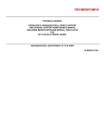
OPERATING AND SERVICE MANUAL
MODEL 431B
POWER M ETER
S E R I A L S P R E F I X E D : 451FOR OTHER S E R I A L S , SEE A P P E N D I X
HEWLETT-PACKARD C O M P A N Y
1962
1501 P A G E M I L L R O A D . P A L 0 A L T O . C A L I F O R N I A . U . S . A .
Copyrcghl
Printed: SEP 1965
Table of Contents
Model 43 1B
TABLE O F C O N T E N T S
Section
I
GENERAL INFORMATION
1.1 . Description
1.6 . Accessories . . . . .
1.8 . Instruments with Options
1.10 . Instrument Identification
Page
1-1
1-1
. 1-2
. 1-2
1-2
.......
...........
....
...
....
11
............
.
...........
.........
INSTALLATION
Inspection . . . . . . . . . .
2.1
Installation
2.3
2.5 . Rack Mounting
2.9
Three-Conductor Power Cable .
2.12
P r i m a r y Power Requirements .
2.15 .
Initial Battery Operation Check
Repackaging for Shipment
2.17 .
.
.
.
.
.
.
.
...
TI1 OPERATION . . . . . . . . . . . . .
Introduction . . . . . . . . . . .
3-1
3 .3 . Mechanical Adjustment of
Meter Zero
3.5 . Controls and Indicators . . . . .
3.7
Operating Instructions
3.9 . Battery Operation
3.11 .
Battery Charging Times . . . .
Battery Charge Check . . . . .
3.13
3.15 . Major Sources of E r r o r , Microwave
Power Measurements
3.17
Power Meter Accuracy of 1%o r
Greater Using the DC Substitution
Method
3 -2 1. Equipment Used f o r DC Substitution
3.24 . Additional Applications . . . . .
.
..........
......
........
.
.
.....
.
............
IV THEORY O F OPERATION
.
.
V
2-1
2-1
2 -1
2 -1
2-2
2-2
2-3
2-3
.
.
.
.
3-1
3-1
3-1
APPENDIX
.MANUAL
Page
4-4
4-4
4-4
4-5
....
....
.....
........
........
......
....
.......
.......
............
.
.
.
3-5
3-5
3-5
..
..
..
..
..........
.....
.
.
.
3-1
3-1
3-1
3-1
3-1
3-1
.
.
.
.
5-1
MAINTENANCE
5-1
5.1 . Introduction
5 .4 . Cover Removal and Replacement . 5-1
Top Cover Removal
5-1
5.6 .
Top Cover Replacement
5-1
5.7
Bottom Cover Removal
5-2
5.8 .
5.9 .
Bottom Cover Replacement . . 5-2
Side Cover Removal
5-3
5.10 .
5-3
5- 12 . Test Equipment
Troubleshooting
5-3
5.14
The Power Supply
5-3
5.17 .
5.21
10-KC Oscillator -Amplifier Check 5-4
5.27 .
10.KCAmplifierCheck
5-7
5.32 .
Metering and Feedback Circuit . 5-7
5-7
5.34 . Squaring Circuit Checks . . . .
5-7
5-40 Battery and Charging Checks . .
Battery Check . . . . . . . .
5-7
5.42 .
Charging Checks
5-8
5.45
Battery Warranty
5-8
5.50
5-8
5.52 . Repair
5.54 . Mechanical Adjustment of
Meterzero
5-8
5-9
5.56 . Adjustments
5.57
Power Supply Adjustments . . 5-9
5.58
Oscillator Frequency Adjustment 5-9
Coarse Null Adjustment
5-9
5.63 .
5.69
Zero and Vernier Control
5-10
Adjustment
5.70 .
Full Scale Accuracy Adjustment 5-10
5-10
5.71 . Performance Check
5.74 .
Zero Carry-Over Check . . . 5-10
5.75 .
Calibration and Range Tracking
5-11
Accuracy
.
.
..
..
..
..
.....
.....
.
.....
........
Meter Circuit
DC Calibration and Substitution
Regulated Power Supply
Power Switch
.
.......
....
....
....
.
4.1 . Overall Description
4.6 . Circuit Description
4.7 .
R F Bridge Circuit
4.12
Metering Bridge Circuit
4.17.
Synchronous Detector
4.21 . Differential Amplifier Q104/Q105
Feedback Current Generator Q107
4.23 .
.
Section
4.25
4-3 1.
4.33 .
4.36
.........
..........
....
.........
......
.........
VI
CHANGES
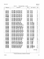
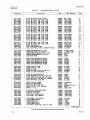
REPLACEABLE PARTS
Introduction . . . .
6.1
Orderinginformation
6.4
.
.
. . . . . . . . .
.
i-1
.
.
.
.
a
.
......
......
6-1
6-1
6-1
List of Illustrations and Tables
Model 431B
LlST O F ILLUSTRATIONS
Number
Title
1.1 . Mode1 431B Power Meter
2.1
2 .2
2.3
2.4
2.5
3.1
3.2
3.3
3.4
3.5
3.6
3.7
3.8
.
.
.
.
.
.
.
.
.
.
.
.
.
........
Page
1-0
The Combining Case . . . . . . . . . .
Steps to Place Instrument into
Combining Case . . . . . . . . . . .
Adapter F r a m e Instrument Combinations .
Two Half Modules in Rack Adapter
Repackaging for Shipment . . . . . . .
2-1
....
Front and Rear Panel Controls and
Indicators
Turn-On and Nulling Procedure . .
DC Substitution Technique
Permanent Record
Increased Resolution . . . . . . .
Leveler Setup . . . . . . . . . .
Monitor Control Systems
Determining Insertion Loss o r Gain
...........
....
.......
.....
2-2
2-2
2-3
2-3
Number
Title
4.1 . Block Diagram
4.2 . R F Circuit
4.3 . Metering Bridge Circuit . . .
4.4 . Nulling Circuit
4.5 . Synchronous Detector
4.6 . Differential Amplifier . . . .
4.7 . Feedback Current Generator
4.8 . Meter Circuit
4.9 . DC Calibration and Substitution
4.10 Regulated Power Supply
4.11 . Power Switch Arrangement
...........
.............
....
...........
.........
....
.....
............
....
........
......
.
5.1
5.2
5 .3
5 .4
.
.
.
.
..
.....
...
LlST O F TABLES
Number
Title
1.1 . Specifications . . . . . . . .
1.2
Model 431B Thermistor Mounts
.
3.1
.
.....
.
.
s
e
e
Voltmeter Readout to Power Multipliers
.
Page
1-1
1-2
3-6
. . . . . . . . . . . . 5-1
. . . . . . . . . . . . 5-3
. . . . 5-5
. . . . . . 5-5
. . . . . . . . . . . . . . . 5-5
. . . 5-5
. . . . . 5-5
. . . . . . . . . . . . . . . . 5-11
. Reference Designation Index . . . . . . 6-2
. Replaceable P a r t s . . . . . . . . . . . 6-8
Test Equipment
Troubleshooting
Power Supply DC Voltage Checks
Power Supply Ripple Checks
10-kc Oscillator-Amplifier DC Voltage
Checks
10-kc Amplifier DC Voltage Checks
DC Voltages in Squaring Circuit
Data for Calibration. Tracking Accuracy
Check
6.1
6.2
6.3 . Code L i s t of Manufacturers
.........
.........
........
.........
Cover Removal
Top View
Power Meter Assembly
Power Supply
.......
6-11
Page
4-0
4-1
4-2
4-2
4-3
4-3
4-3
4-4
4-4
4-5
4-5
Section I
Model 43lB
Figure 1-1
Figure 1-1. Model 43LB Power Meter
Section I
Paragraphs 1-1 to 1-4
Model 431B
SECTION I
GENERAL I N F O R M A T I O N
1-1. DESCRIPTION.
1-2. The $ Model431B Power Meter, with @ temperature compensated thermistor mounts, measures rf
power from 10 microwatts (-20 dbm) to 10 milliwatts
(+lo dbm) in the
40-gc
range.
Direct reading accuracy of the instrument is *3% of
full scale. Instrument specifications a r e given in
table 1- 1.
electrically isolated. One thermistor i s used to
absorb rf power; the other i s used to provide temperature compensation. Thus, the thermal drift problems
normally associated with the thermistor-power meter
arrangement have been greatly reduced. A single
setting of the ZERO control on the most sensitive
power range is maintained within *0.5% for all higher
power ranges.
1-3. The design of the Model 431Bandits thermistor
mount, results in almost complete freedom f r o m
nleasurement e r r o r caused by ambient temperature
changes.
The instrument incorporates two selfbalancing bridges with one a r m of each bridge being
a thermistor. The two matched thermistors,, both
located within the mount, a r e thermally coupled, but
1-4. The temperature compensated
thermistor
mounts used with the instrument a r e specifically designed for ?$ Model 4 3 1 ~ / BPower Meters. Coaxial
and waveguide thermistor mounts cover the 10-mc to
40-gc frequency range. Table 1-2 gives thermistor
mount operating frequency, mount configuration, and
operating resistance.
Table 1- 1. Specifications
Instrument Type:
Automatic, self-balancing for temperature compensated mounts
Power Ranges:
7 ranges with full scale readings of 10, 30, 100
and 300 pw; 1, 3 and 10 mw. Also calibrated in
dbnl from -20 to + l o .
External Bolometer:
Temperature-compensated thermistor mounts
required for operation ($ 478A and 486A s e r i e s ) .
Accuracy:
i30/0 of full scale from +20°C to+35"C, i50/0 of full
scale from 0°C to +55"C
Zero Carry-Over:
Less than 0.5% of full scale when zeroed on most
sensitive range
Recorder1 Voltmeter Output:
Phone jack on r e a r with 1 ma maximum into 1000
ohms *lo(%;one side grounded
Calibration Input:
Bindi~lgpostson r e a r for calibration of bridge with
$ 8402A Power Meter Calibrator o r precise dc
standards
Power Supply:
115 o r 230 voltsi100/o, 50 to 1000 cps, 2-1!2 watts
Dimensions:
6-171 32 in.(166 m m ) high, 7-251 32 in. (198 n ~ l n )
wide, 12- 11 2 in. (37 8 mm) deep
Weight:
Net 8 lb (3.63 kg) withcover and cables 11-1/2 lb
(5.44 kg) including battery; shippingapprox. 131b
(5.9 kg)
Accessories Furnished:
5 ft (1.5 m) cable for @ temperature-compensated
thermistor mounts. 7-1/2 ft (2.3 m) power cable,
NEMA plug.
Accessories Available:
431A-95B Rechargeable Battery Pack for field
installation.
$ Models 478A and 486A Thermistor Mounts
&, Model 8402A Power
Meter Calibrator
.@ Model HOI-8401A Leveler Amplifier
Options:
01. Rechargeable battery installed, provides up
to 24 hours continuous operation,
02. Rear input connector wired in parallel with
front panel input connector,
10. With 20 foot cable for 100 52 o r 200 52 mount,
11. With 50
foot cable for 100 52
mount,
12. With 100 foot cable f o r 100 51
mount,
13. With 200 foot cable for 100 52
mount,
21. With
50 foot cable f o r 200 52
mount,
22. With 100 foot cable for 200 52
mount,
23. With 200 foot cable for 200 W
mount.
1
Model 431B
Section I
Paragraphs 1-5 to 1-11
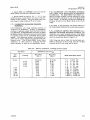
Table 1-2. Model 431B Thermistor Mounts
1
Frequency
Range
Operating
Resistance
in ohms
10 mc to 10 gc
200
@ S486A
2.6 to 3.95 gc
100
@ G486A
3.95 to 5.85 gc
100
@J486A
5.3to8.2gc
100
Type
Coaxial
Waveguide
@ 478A
alone. In addition a jack in s e r i e s with the panel meter
permits digital o r chart recording of measurements,
operation of a l a r m o r control systems and use in a
closed-loop leveling system.
1-6. ACCESSORIES.
1-7. Two accessories a r e supplied with the Model
431B Power Meter: a 7-1/2-foot, detachable power
cable and a 5-foot cable that connects the thermistor
mount to the Mode1 431B. Thermistor mounts a r e
available (see table 1-2) but not supplied with the
instrument. A rechargeable battery with installation
kit is also available. A list of supplied and available
accessories i s given in table 1-1, Specifications.
1 - 8 . INSTRUMENTS WITH OPTIONS
1-9. The options available with the Model 431B
Power Meter a r e given in table 1-1. The thermistor
mount cable options require modification and recalibration of the Model 431B Power Meter. The recalibration procedures for the cables a r e given in section
V, Maintenance, under Oscillator Frequency Adjustment (paragraph 5-58) and Coarse Null Adjustment
(paragraph 5-63).
I * With circular contact flange adapter
1
1-5. The Model 431B has provisions for using the
dc substitution method of measurement and for checking calibration accuracy of the power meter. The dc
substitution method of measurement which requires
other equipment provides greater power measurement
accuracies than can be obtained by the power meter
1-10. INSTRUMENT IDENTIFICATION.
1-11. Hewlett-Packard uses a two-section eight-digit
s e r i a l number (000-00000). If the f i r s t three digits of
the s e r i a l number on your instrument do not agree with
those on the title page of this manual, consult the Appendix for information regarding manual changes.
Section LI
Paragraphs 2-1 to 2-8
Yodel 431B
SECTION II
2-1. INSPECTION.
2-2. This instrument was carefully inspected both
mechanically and electrically, before shipment. It
should be physically free of mars or scratches and in
perfect electrical order upon receipt. To confirm this,
the instrument should be inspected for phyaical damage
in transit. Also check for supplied accessories, and
test the electrical performance of the instrument using
t&e procedure outlined in paragraph 5-71. If there is
damage or deficiency, see the warranty on the inside
rear cover of this manual.
2-3. INSTALLATION.
2 4 . The @ Model 431B is fully transistorized; therefore no special cooling i s required. However, the
instrument Bhould not be operated where the ambient
temperature exceeds 55'C (140°F).
2-5. RACK MOUNTING.
2-6. The Model 431B i s a submodular unit that when
used alone can be bench mounted only. However,
when used in combiition with other mbmcdular units
it can bebench and/or rack m n t e d . The @ combining
case axxi adapter frame are designed specifically for
this purpose.
2-7. COMBINING CASE. The combining case is a
full-module unit which accepts varying combinations
of submodular units. Being a full-module unit, it can
be bench or rack mauntedanalogoustoany full-module
instrument. A n iiluetration of the combining case is
shown in figure 2-1. Instructions for installing the
Model 431B in a combining case are given graphically
in figure 2-2.
2-8. ADAPTER FRAME. The adapter frame is
a rack frame that accepts any combination of s u b
modular units. It can be rack mounted only. An
ilbustration af the adapter frame isgiven in ifgure 2-3.
To assemble, refer to Figure 2 4 and proceed as
follows:
a. Place the a c l a ~ e rframe (1) on edge of bench as
illustrated.
b. Stack the submodular units (2) in the frame.
c. Place the spacer clamps (3) between instruments.
d. Place spacer clamps (4) on the two end instruments.
e. Push the combhation into the frame.
MBLY
SUBMODULE RETAINER
Figure 2-1. The Combining Case
Section I1
Paragraphs 2-9 to 2-13
STEP
a
SLIDE TOP
TO LIMIT
PART
Model 431B
byT(\
I
STEP
@
o&
SLIDE BOTTOM PART
TO L l M l T
PUSH DOWN
&n
U
Y
STEP
STEP
@
PLACE INSTRUMENT
INTO CASE
@
PUSH I N TO LlMlT
..
-
. -.
-.
.
Y..
SET RETAINER BACK
INTO PLACE
SLIDE OVER TO L l M l T
PUSH UP TO LOCK
Figure 2-2. Steps to Place Instrument into Combining Case
I
FILLER PANEL
I
\
L 0
O
0
0
0
0
0
0
0
f. Insert screws (5) on both sides of frame, and
tighten until submodular instruments a r e secure in
frame.
g. The complete assembly is ready for rack
mounting.
2-9. THREE-CONDUCTOR POWER CABLE.
2-10. T o protect operating personnel, the National
Electrical ManufacturersJ Association (NEMA) recommends that the instrument panel and cabinet be
grounded.
All Hewlett-Packard instruments a r e
equipped with a three-conductor power cable which,
when plugged into an appropriate receptacle, grounds
the instrument. The offset pin on the power cable
three-prong connector is the ground wire.
2-11. To preserve the protection feature when operating the instrument from a two-contact outlet, use a
three-prong to two-prong adapter and connect the
green pigtail on the adapter to ground.
2-12. P R I M A R Y P O W E R R E Q U I R E M E N T S .
L D S U O
Figure 2-3. Adapter Frame Instrument Combinations
2-13. The Model 431B can be operated from an a c o r
dc primary power source. The a c source can be either
115 o r 230 volts, 50 to 1000 cps. The dc source i s a
24-volt rechargeable battery.
The rechargeable
battery is supplied with option 01 instruments only.
Section I1
Paragraphs 2-14 to 2-18
Model 431B
2-14. For operation from a c primary power, the
instrument can be easily converted from 115- to 230volt operation. The LINE VOLTAGE switch, S1 a
two-position slide switch located at the r e a r of the
instrument, selects the mode of a c operation. The
line voltage for which the instrument is set to operate
appears on the slider of the switch. A 15/100-ampere,
slow-blow fuse i s used for both 115- and 230- volt
operation.
CAUTION
DO NOT CHANGE THE SETTING O F THE
LINE VOLTAGE SWITCH WHEN THE POWER
METER IS OPERATING.
2-15. INITIAL BATTERY OPERATION CHECK.
2-16. The following applies to option 01 instruments
o r instruments that have field-installed batteries.
When the battery is used a s the Model 431B power
source for the first time, perform the following steps:
a. Connect Model 431B to a c source. Set POWER
switch to CHARGE and charge battery for a minimum
of 16 hours o r overnight. Note: the battery can be
maintained in the charging state indefinitely without
damaging the battery. It will assume i t s full capacity,
1.25 ampere hour, and no more.
b. Perform turn-on procedure given in figure 3-2
with POWER at AC.
If the procedure checks out
normally, proceed to step c.
c. Repeat turn-on procedure given in figure 3-2
with POWER a t BATTERY ON. If operationis not the
s a m e a s that obtained with a c power applied, refer to
paragr:: 5-40, Battery and Charging Checks.
'.
2-17. REPACKAGING FOR SHIPMENT.
2-18. The Model 431B i s shipped in a foam-pack and
cardboard carton (see figure 2-5). When repackaging
the instrument for shipment, the original foam-pack
and cardboard carton can be used if available. If not
available, they can be purchased from Hewlett-Packard
Co. (refer to section VI, misc). Use the following a s
a general guide for repackaging the instrument.
a. Place the instrument in the foam-pack a s shown
in figure 2-5.
b. Mark the packing box with "Fragile",
Instrument. "
"Delicate
Note
If the instrument is to be shipped toHewlettPackard for service o r repair, attach to the
instrument a tag identifying the owner and
indicating the service o r repair to be accomplished, include the model number, and full
s e r i a l number, of the instrument. In any
correspondence, identify the instrument by
model number, serial number and s e r i a l
number prefix.
0
aDAPTER
FRAME
Figure 2-4.
01370-3
Two Half Modules i n Rack Adapter
Figure 2-5. Repackaging for Shipment
2-3/2-4
Section I11
Paragraphs 3-1 to 3-16
Model 431B
S E C T I O N Ill
OPERATION
3-1. INTRODUCTION.
3-2. The @ Model 431B Power Meter measures rf
power ranging from .O1 t o 10 milliwatts with power
meter accuracy of *3%. The zero c a r r i e s over from
range to range within +0.5% of fullscale whenthe met e r i s zeroed on the most sensitive scale.
3-3. MECHANICAL ADJUSTMENT OF
METER ZERO.
3-4. The procedure for performing the mechanical
adjustment of the meter zero is given in section V,
paragraph 5-54.
3 - 5 . CONTROLS A N D INDICATORS.
3-6. The front and r e a r panel controls and connectors
a r e explained in figure 3-1. The explanations a r e
keyed to corresponding controls and indicator on the
drawing of the front and r e a r panels of the instrument
provided with the figure.
3 - 7 . OPERATING I N S T R U C T I O N S .
3-8. Figure 3-2, Turn-On and Nulling Procedure,
and figure 3-3, DC Substitution Technique, give stepby-step instructions for operating the Mode1 431B. In
figure 3-2, each step is numbered to correspond with
numbers on the accompanying drawing of the power
meter.
3-9. BATTERY OPERATION.
3-10. The following applies t o power m e t e r s having
a factory o r a field-installed rechargeable nickel-cadmium battery. See figure 3-1, Turn-On and Nulling
Procedure, for step-by-step instructions for operating
the Model 431B from a battery.
3-11. BATTERY CHARGING TIMES.
3-12. The battery used in the Model 431B requires
two hours of charge time for one hour of battery
operation.
When the battery is fully charged, the
Model 431B can be continuously operated for 24 hours
with 48 hours of charge time. However, i t i s recommended that battery operated instruments be operated
for eight hour periods with a 16 hour recharge time.
This makes the Model 431B available for portable
use daily, yet maintains the battery a t full charge.
3-13. BATTERY CHARGE CHECK.
3-14. Under normal conditions, a fully charged
battery will s t a r t a t approximately 27 volts and drop
to about 22 volts after 24 hours of continuous use a t
room temperature.
a. Connect the Model 431B to a c primary power.
Set POWER to AC and perform the turn-on and nulling
procedure given in figure 3-2. This will check for
normal operation from a c primary power. If performance is normal proceed to step b.
b. Set POWER t o BATTERY CHARGE:
the AC
CHARGE lamp will glow. Allow Model431B to charge
the battery for 48 hours. This will allow the battery
t o obtain a full charge.
c. After the recharge interval, set POWER to
BATTERY ON. Since battery i s now fully charged.
you should be able to z e r o i s e t and null-the meter
(figure 3-2). If not the battery o r battery charging
circuit is a t fault. Refer t o Battery and Charging
Checks paragraph 5-40.
3-15. MAJOR SOURCES OF ERROR, MICROWAVE
POWER MEASUREMENTS.
3-16. In microwave power measurements, the following a r e the major sources of e r r o r : 1) mismatch e r r o r
o r tuner l o s s (when a tuner is used to tune out mismatch
e r r o r ) , 2) bolometer mount efficiency, 3) substitution
e r r o r , 4) instrument e r r o r and 5) e r r o r due to the
unilateral properties of a thermistor. Thus five e r r o r s
must be known if accurate power measurements a r e
to be obtained. Expressed mathematically:
Total measurement e r r o r =
mismatch (or tuner) loss + calibration factor +
instrument e r r o r + e r r o r due to the unilateral
properties of a thermistor
a. Mismatch Loss. Unless the mount and rf source
a r e perfectly matched to the transmission system, a
fraction of incident power is reflected and does not
reach the thermistor. Since there generally i s more
than one source of mismatch in a microwave measurement system and the resulting e r r o r signals interact, l o s s cannot be calculated from the s w r figure, i t
can only be expressed a s lying between two limits.
Limits of mismatch l o s s generally a r e determined by
means of a chart such a s the Mismatch Loss Limits
chart included in each of the thermistor mount
Operating Notes. A tuner such a s the @ Model 872A
o r 870A can be used to minimize loss, although the
tuner itself will introduce some loss.
b. Bolometer Mount Efficiency and Substitution
E r r o r . Not all the rf power applied to the mount is
used to heat the rf thermistor. someof it is absorbed
by the other elements i n the mount, such a s the walls
of the rf chamber, the heat sinks, the leads, etc. Substitution e r r o r results because rf power does not affect
the thermistor t o the same degree a s dc power. Substitution e r r o r and mount efficiency a r e often combined
forsimplicity of measurement into what is termed
"calibration factor". Typically, the calibration factor
of the Model X486A waveguide mount is 97% to 98%.
Model 431B
Section III
Figure 3-1
I. POWER: The POWER switch s e t s up connections
to the selected power sources o r to the battery
charging circuit. When the power switch is in
the AC position, externally supplied 115 o r 230
volts is applied to the instrument. If the instrument contains a battery, a trickle charge is
applied to maintain the battery a t full charge.
With POWER a t BATTERY ON, a 24-vdc battery
within the instrument supplies primary power
to the instrument. With POWER a t CHARGE,
115- and 230-volt power is used to charge the
battery (16 to 24 hours is required to obtain
full battery charge). The instrument is inoperative in this position. Note: Batteries
a r e installed a t the factory for option01 instruments only.
4. MOUNT m S : This two -position slide switch
s e t s the power meter to accommodate thermistor mounts of 100- o r 2 0 0 - o h m n o m i n a l
resistance.
5. Z E R O and V E R N I E R : The Z E R O c o n t r o l
coarsely s e t s the meter pointer near zero; the
VERNIER control is a more exact adjustment
which s e t s the meter pointer on zero.
6. Ln Option 02 instruments only, mount connector
wired in parallel with front - panel connector.
Two mounts cannot be connected simultaneously.
7. RECORDER: The RECORDER input i s a grounded
telephone jack for monitoring the current which
operates the Model 431B meter.
8. D C CALIBRATION & SUBSTITUTION: T h i s
2. RANGE: The RANGE switch can be s e t for full
scale power readings from .O1 to 10 milliwatts
in seven steps. It also includes a NULL position which, in conjunction with the adjacent
null screwdriver adjust, insures that the metering bridge is reactively balanced.
terminal permits application of known direct
current to the rf bridge. The power reading
obtained with the accurately known dc power
applied i s then compared with the reading obtained when rf power was applied. The dc substitution technique is used both to calibrate the
431B and to increase the accuracy of p o w e r
measurement.
3. THERMISTOR MOUNT:
The THERMISTOR
MOUNT connector is a female receptacle that
accepts a specially-made cable whichis supplied
with the instrument. The cable connects the
mount thermistors into their respective bridges
within the power meter.
9. LINE VOLTAGE: The LINE VOLTAGE switch,
S1, is a two-position slide switch that selects
the mode of ac operation. The line voltage for
which the instrument is set to operate appears
on the slider of the switch. A 15/100 slow-blow
fuse is used for both 115 and 230volt operation.
Figure 3-1. Front and Rear Panel Controls and Indicators
Model 431B
Section III
Figure 3-2
II
4318 POWER M E T E R
POWER
OFF
AC
1"
a.TTrml(
.ox .m
.1
.s
I
II
3 60
THERMISTOR
MOUNT
Imn loon
m1. Connect thermistor mount and cable to the
THERMISTOR MOUNT. ($0 thermistor mounts
and their frequency ranges a r e given in table
1-2, Model 431B Thermistor Mounts.
Note
When possible, the Model 431B should be
zeroed and nulled with the power source to
be measured connected to the thermistor
mount. If this is not possible, and a coaxial
thermistor mount is used, terminate the
rf input into a 50-ohm load. Power source
should be off while zero and null-setting
the Model 43133 Power Meter.
2. Set MOUNT RES to match thermistor mount
resistance (100 o r 200 ohms).
3. Set RANGE to .O1 MW.
4, Set POWER to AC; AC & CHARGE lamp will
glow. If instrument i s battery-operated, rotate
POWER to BATTERY ON.
5. Adjust ZERO control for 25 to 75% of full scale
on meter.
6. Rotate RANGE to NULL and adjust null screw-
driver adjust (adjacent to NULL on RANGE
switch) for a minimum reading.
LO-M-604
7. Repeat steps 5 and 6 until NULL reading i s
within NULL region on the meter.
Note
If instrument i s battery-operated and you
a r e not able to zero the meter, o r if meter
pointer fluctuates rapidly, battery needs
recharging. Refer to paragraph 3-11.
8. Set RANGE switch to the power range to be used
and zero-set the meter with ZERO andVERNIER
controls.
Note
Zero-set accuracy of 0.5'hof full scale can
be obtained by zero setting the meter on the
most sensitive range (. 01 mw) only, and
assumingthe meter is properly zeroed on
all less sensitive ranges. For maximum
accuracy, zero set the meter on the range
to be used.
9. Apply rf power a t the thermistor mount and
read power on Model 431B meter. Power i s
indicated on the meter directly in mw o r dbm.
Note
This instrument is accurate to withini3%.
Accuracy to *I%, or better, is possible
using the dc substitution technique described in figure 3-3. See alsoparagraphs
3-15 and 3-17.
-
Figure 3-2. Turn-On and Nulling Procedure
Section I11
Figure 3-3
Model 431B
POWER SUPPLY
0-300vdc
\
DIGITAL VOLTMETER
",.Po
,r2cy:
0.2%
35BR/CR
1
@MODEL 4318
POWER METER
n
r[
IK, .05%. I W
LO.".$,.
IOK. IOO/o. IOW
I
1. With power supply turned off, connect the
Model 431B a s shown above.
2. Set the Model 431B for normal operation on the
appropriate range using the procedure given in
figure 3-2.
3. Apply rf power a t the thermistor mount and
note and record the reading of the Model 431B
meter. This i s the reference for the substitution measurement.
Note
CAUTION
Never apply more than 20 ma dc to the DC
CALIBRATION & SUBSTITUTION terminals of the Model 431B.
6. Read the voltmeter which monitors the substitution current. The voltmeter reading can be
interpreted a s current in milliamperes because
the voltage is measured across 1000 ohms.
This current is Id,.
7. Calculate power in mw from the expression
A second digital voltmeter, in parallel
with a 1000-ohm (*lo%, 1 watt) resistor,
connected in s e r i e s with the RECORDER
output of the Model 431B will increase
accuracy of reference duplication.
4. Turn off, o r disconnect, the rf source.
5. Turn power supply on; adjust the output voltage
of the power supply until the reference of step 3
is duplicated. A potentiometer arrangement
may be substituted for the adjustable power
supply. However, at least 10,000 ohms must
remain in series with the supply.
Power (MW) =
"dc
Rd
4 x 10³
where Rd = operating resistance of the termistor (100 o r 200 ohms)
and Idc = substitution current in milliamps
(from step 6)
9. To minimize e r r o r due to drift in either the
reference o r substituted power level, steps 1
through 6 should be repeated.
-
-
-
Figure 3-3. DC Substitution Technique
01370- 2
Section III
Paragraphs 3-17 to 3-26
c. Instrument Error. This is the inability of the
power meter to accurately measure and interpret the
information available a t the thermistor element. In
specifying the accuracy of a power meter, instrument
e r r o r is the figure usually given. For the Model 431B,
instrument e r r o r is lt3% of full scale, 20°C to 35°C.
This e r r o r can be reduced by special techniques such
a s the dc substitution method discussed in para. 3-17.
d. E r r o r Due to the Unilateral Properties of a
herc cis tor. The thermistor used in conjunction with
b. how accurately the value of the substituted dc is
known,
c. the actual operating resistance of the thermistor,
and
d. the actual ratio of current division in the rf bridge.
3-20. With precision components in the substitution
setup and careful procedure, e r r o r produced by the
Model 431B Power Meter canbe reducedto 1%o r less.
This is assuming nominal thermistor mount resistance
(100 or 200 ohms) and that half the applied dc flows
through the rf thermistor. The dc substitution technique using the Model 431B is shown in figure 3-3.
/ ~
unilateral properties which,
the Model 4 3 1 ~ exhibits
when the source of power is a dc current, causes a
slightly different indication of power than is obtained
by the calculation of I ~ R . Thus thedc power required
/ ~
to produce a reading on the Model 4 3 1 ~ Power
3-21. EQUIPMENT USED FOR DC SUBSTITUTION.
Meter is not the same a s the rf power required to
r
produce the same reading on the ~ o d e l 4 3 1 ~ / ~ ~ o w e 3-22.
The @ Model 8402A Power Meter Calibrator
Meter. The maximum e r r o r produced from this source
was specifically designed to be used for calibration
of e r r o r is 10.3 pwatts, typical e r r o r is lt0.1 pwatt.
and dc substitution measurements of rf power. In
Since the order of magnitude of this e r r o r is small
addition, the instrument will accurately measure the
(0.3 pwatt) it need be minimized pnly on the two most
operating resistance of the thermistor mount being
sensitive ranges of the Model 431A/B Power Meter.
used. Use the procedures given in the manual provided
Refer to the @ Model 8402A Power Meter Calibrator
with the @ Model 8402A Power Meter Calibrator to
manual for procedure used to minimize this error.
perform the d c substitution measurements.
3-17. POWER METER ACCURACY OF 1% OR
GREATER USING THE DC SUBSTITUTION
METHOD.
3-18. Highly accurate instruments a r e available for
measuring direct current. Thus, where optimum
accuracy is required, there is considerable advantage
in using a technique where the rf measurement is
used only a s a reference and the determination of rf
power is based on precise dc measurements. In
general the technique involves:
a. Applying rf power to the Model 431B inthe usual
manner, and noting the resulting meter indication for
use a s a reference.
b. Removing the rf power and applying sufficient dc
a t the DC CALIBRATION & SUBSTITUTION terminals
to exactly duplicate the meter indication produced by
the rf power.
c. Using the value of dc which duplicated the reference in calculating rf power.
3-19. Although the dc substitution technique is the
most accurate method of measuring rf power, there
a r e sources of e r r o r that must be considered. The
accuracy of the dc substitution technique depends
largely upon:
a. how precisely the reference is duplicated,
RF SOURCE
(
TEMPERATURE
COMPENSATED
THERMISTOR
MOUNT
@ 478A. 486A)
3- 23. Although the most convenient and accurate means
of applying the dc substitution technique is by using
@ Model 8402A Power Meter Calibrator, it is also
possible to accurately measure power using the dc
substitution technique with the arrangement shown in
figure 3-3. The digital voltmeter is used to monitor
the substitution current. The power supply output and
voltmeter input a r e ungrounded to eliminate ground
currents.
3-24. ADDITIONAL APPLICATIONS.
3-25. At the RECORDER output, the Model 431B furnishes a current (0 to l ma dc) which is proportional
to the power measured. This feature makes possible
a measurement system with more capability than
simply the indication of power on a meter. Some of the
more sophisticated measurement systems a r e shown
in block diagram form in figures 3-4 through 3-8.
3-26. PERMANENT RECORD. Use of a recorder in
the measurement system is indicated in figure 3 -4.
Resistance across the Model 431B RECORDER output
should be 1000 ohms 110% f o r optimum measurement
accuracy. Any type of recorder may be used with the
Mode1 431B; if input resistance exceeds 1000 ohms,
use a shunt across the recorder input.
9 MODEL 4318
4
Figure 3-4.
.
J IOZ
RECORDER
POWER
METER
Making a Permanent Record
looon
INPUT
RECORDER
Section 111
Paragraphs 3-27 to 3-30
RF SOURCE
*
--o
Model 431B
TEMPERATURE
COW PENSATED
THERMISTOR
MOUNT
( ,@ 4 7 8 A , 4 8 6 A )
--c
I;p MODEL 4318
POWER
METER
Figure 3-5. Obtaining Increased Resolution
Model 431B and i t s thermistor mount, such a leveling
system requires the @ H01-8401A Leveler Amplifier
and a directional coupler with good directivity suchas
one of the @ 752 series of waveguide couplers o r 770
series of coaxial couplers. The output of the power
source is sampled by the coupler and applied to the
Model 431B. A dc signal, proportional to the power
sample, is fed (from the Model 431B RECORDER jack)
to the Leveler Amplifier. In the H01-8401A the signal
from the Model 431B is compared to an internal reference voltage, and the difference is amplified and fed
back a s a controlvoltage to hold output
power constant.
-
3-27. INCREASED RESOLUTION. Digital readout of
power to three decimal places can be obtained with the
arrangement shown in figure 3-5. The value of R1 is
316.2 ohms *. 1%and
is 1000 ohms ~ 1 %Correct
.
placement of the decimal in the readout isdetermined
by the setting of the power meter RANGE switch. On
the divider-switch arrangement at the voltmeter input
may be replaced by a single 1000-ohm .l%resistor.
With this arrangement, on the .01, .I, and 10 MW
ranges, power is read in the same way a s when the
arrangement shown in figure 3-5 is used, decimal
placement being determined by the setting of RANGE.
o n the .03, .3,- and 3 MW ranges, however to obtain
the power readings the voltmeter indication must be
multiplied by the factor given in table 3-1.
3-29. MONITOR
SYmEMS. BY adding a
dc amplifier and relay circuit to the rf monitoring arm
of a system, the dc signal provided by the Model 431B
can be used to actuate alarm o r control circuits. Arrangement of equipment to provide an alarm o r control
system is shown in block diagram form in figure 3-7.
Table 3-1. Voltmeter Readout to Power Multipliers
3-30. DETERMINING INSERTION LOSS OR GAIN AS
A FUNCTION OF FREQUENCY. Arrangement of a
system to obtain information on insertion loss o r gain
a s a function of frequency is indicated in figure 3-8.
Initially, the device under test is not connected into the
system; connect the thermistor mount directly to the
sweep oscillator. Set the sweep oscillator for the band
of interest, and record variations in amplitude a s
frequency is swept; this curve is the reference. Next,
insert the device under test between the sweep
oscillator and the thermistor mount, and again record
frequency response.
The difference between the
second reading and the reference, at any one frequency,
is the insertion loss o r gain of the device at that
frequency.
Multiplier
.03 MW
3-28. LEVELER. Figure 3-6 is a block diagram of
a closed-loop control circuit for maintaining output
power at a constant level. It is recommended for use
in leveling the output of various types of @ microwave
equipment such a s bwo sweep oscillators, twt microwave amplifiers, and rf generators. In addition to the
-
RECORDER
-
AMPLITUDE
MODULATION
INPUT
TEMPERATURE
COMPENSATED
THERMISTOR
WOUWT
@ 478A.486A
-
INPUT
-
@HOI-8401~
LEVELER
AMPLIFIER
Dl RECTIONAL
SOURCE
1
-
CONTROL VOLTAGE (NEGATIVE FEEDBACK)
Figure 3-6. Leveler Setup
I
Section III
F i g u r e s 3-7 and 3-8
Model 43 1B
t
-
TEMPERATURE
COMPENSATED
THERMISTOR
MOUNT
@o78~.486~
?
.
Figure 3-7.
-
Rf
Rf
OUTPUT/SWEEP
OSClLLATOR
-
MICROWAVE
OEVICE
'9MODEL 4318
J102
RECORDER
DC
AMPLIFIER
ALARM.
CONTROL,
7 PROTECTIVE.OR
CORRECTIVE
DEVICES
L
= RELAY
METER
looon.
B D - 5 - 255
Monitoring Control Systems
TEMPERATURE
COMPENSATED
THERMISTDR
M UNT
9 &A, 4 8 6 A
$,MODEL 4310
METER
RECORDER
Jl02
Y
INPUT
-
-
SWEEP
OUTPUT
X-Y RECORDER
~ O O O A ~
7
X
1 NPUT
*
3
80-5-256
F i g u r e 3-8. Determining Insertion Loss o r Gain
Section N
Figure 4-1
'
Model 43 1B
7-----
'
DC C A L I B R A T I O ~
8 SUBSTITUTION
L-----d
5103
>
1
-
--
T
-
-
I IOKC
-
-
b
I
IOKC
OSCILLATOR
AMPLIFIER
9108- 0111
--LEGEND
I IOKC
I DC
1M
IOKC
STNCHROWOUS
DIffERENTIAL
AYPLIFIER
OlO4/0105
.--.
. I
I
4107
-.
r-.
I
FEEDBACKCURREWTSQUARED
GENERATOR
0106
- 1-
_/
1 1 5/23OVAC
50-IOOO-24VDC
OPTIONAL BATTERY
REcuLATED
POWER
SUPPLY
tI.5VDC
. - I8VDC (REG)
1
I
.1
MlOl
Iu
:
--
- 2 5 V D C (REG)
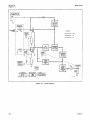
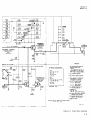
Figure 4-1. Block Diagram
r-----
I I.R-E*!E!;
.D.L.,i.B
Model 431B
Section IV
Paragraphs 4-1 to 4-11
SECTION IV
THEORY O F OPERATION
4-1. O V E R A L L D E S C R I P T I O N .
4-6. C I R C U I T D E S C R I P T I O N .
4-2. Figure 4-1 i s a block diagram which shows the
Model 431B Power Meter and its associated thermistor
mount. The thermistor mount contains two thermistor
elements (Rd and Rc). Thermistor element Rd absorbs
the rf power applied to the mount; thermistor element
Rc converts the applied rf power to a meter indication
and provides compensation for ambient temperature
changes at the thermistor mount.
4-7.
4-3. The power meter circuitry incorporates two
bridges which a r e made self-balancing by means of
separate feedback loops. Regenerative (positive) feedback i s used in the detection loop; degenerative feedback in the metering loop. One thermistor element i s
used in one a r m of each of the self-balancing bridges.
In the detection loop, the 10 kc oscillator-amplifier
supplies enough 10 kc power (Il0 kc) to bias thermistor
element Rd to the operating resistance whichbalances
the rf bridge. The same amount of 10 kc power i s also
supplied to thermistor element Rc by the series-connected primaries of transformers TlOl and T102.
4-4. When rf power i s applied to thermistor element
Rd, an amount of 10 kc power equal to the rf power is
removed from thermistor element Rd by the selfbalancing action of the rf bridge. Since the primaries
of TlOl and TI02 a r e series-connected, the same
amount of 10 kc power is also removed from thermistor
element Rc, thus, the action which balances the rf
bridge unbalances the metering bridge. The metering
bridge loop automatically re-balances by substituting
dc power for 10 kc power. Since the 10 kc power
equaled the applied rf power, the substituted dcpower
is also equal to the applied rf power. Instead of
metering the feedback current directly, which would
require the use of a nonlinear meter scale, an analog
current i s derived which i s proportional to the square
of the feedback. Since power is a square-law function
of current, the analog current thus derived is proportional to rf power, making possible the use of a
linear scale on the meter.
R F BRIDGE CIRCUIT.
4-8. A simplified schematic diagram of the rf bridge
circuit is shown in figure 4-2. The rf bridge circuit
consists of the rf bridge and 10-kc oscillator-amplifier.
The rf bridge includes thermistor Rd, the secondary
winding of T101, resistors R102 andR103, theMOUNT
RES switch, S101, and capacitance represented by Ca
and Cb. The rf bridge and 10 kc oscillator-amplifier
a r e connected in a closed loop (the detection loop) which
provides regenerative feedback for the oscillatoramplifier. This feedback causes the 10 kc oscillatoramplifier to oscillate.
4-9. When the power meter i s off, thermistor Rd i s
at ambient temperature and its resistance is about 1500
ohms; the rf bridge i s unbalanced. When the power
meter is turned on this unbalance of the rf bridge
causes a large e r r o r signal to be applied to the 10 kc
oscillator-amplifier. Consequently maximum 10 kc
bias voltage is applied to the rf bridge. As this 10 kc
voltage biases Rd to i t s operating resistance (100 o r
200 ohms) the rf bridge approaches a state of balance
and regenerative feedback diminishes until there is just
sufficient 10 kc bias power to holdRd at operating resistance.
This condition i s equilibrium for the
detection loop.
4-10. With application of rf power, thermistor Rdls
resistance decreases causing the regenerative signal
from the rf bridge to decrease. Accordingly, 10 kc
power diminishes, the thermistor returns to operating
resistance and the detection loop regains equilibrium.
4-11. The MOUNT RES switch, S101, changes the
resistance a r m of the rf bridge so thatthe bridge will
function with either a 100 o r 200 ohm thermistor mount.
TO METERING BRIDGE
IOKC BIAS
TlOl
4-5. There i s little drift of the power meter zero
point when ambient temperature at the thermistor
mount changes. If, for example, ambient temperature
at the mount increases, a decrease in electrical power
to the thermistors i s required to hold their operating
resistances constant. The decrease, for both thermistors, i s made automatically by the detection loop
(figure 4-1) which reduces 10 kc power. The amount
of dc power in the metering loop remains unchanged
however, and since this dc power controls the meter
action, the a rn b i e n t temperature changes d o n o t
affect the meter indication. The compensation capability depends upon the match of thermistor temperature characteristics. When thermistor mounts a r e
built, the thermistors a r e selected to insure optimum
match of thermal characteristics.
1-
y
v
y
m
d:tk~~4;Ef:
AMPLIFIER
Figure 4-2. R F Circuit
Model 431B
Section IV
Paragraphs 4-12 to 4-19
-
FROM
RF
4- 12. METERING BRIDGE CIRCUIT.
BRIDGE
4-13. A simplified schematic diagram of the metering
bridge circuit is shown in figure 4-3. Operationof the
metering bridge circuit is similar to the rf bridge circuit. It uses the same principle of self-balancing
through a closed loop (metering loop). The major difference i s that dc rather than 10-kc power i s used to
rebalance the loop. The resistive balance point i s
adjusted by the ZERO and VERNIER controls which
constitute one a r m of the bridge. The MOUNT RES
switch (not shown in figure 4-3) which i s mechanically
linked to both the rf bridge and metering bridge,
changes metering bridge reference resistance from
100 to 200 ohms. When the MOUNT RES switch is in
the ZOO-ohm position some of the feedback current i s
shunted to ground through R101. This maintains the
I ~ R
function constant when mount resistance i s changed
from 100 o r 200 ohms. The switch also adds the
necessary reactance for each position.
4-14. The same 10 kc power change produced in the rf
bridge by rf power also affects the metering bridge
through the series connection of TlOl and TI02 primaries. Although this change of 10-kcpower has equal
effect on both the rf and metering bridges, it is initiated
by the rf bridge circuit alone. The metering bridge
cannot control 10-kc bias power, but the 10-kc bias
power does affect the metering circuit. Once a change
in the 10-kc bias power has affected (unbalanced) the
metering bridge, a separate, closed dc feedback loop
(metering loop) re-establishes equilibrium in the
metering circuit.
TI02
BRIDGE
COMPENSATION
THERMISTOR
Figure 4-4. Nulling Circuit
4-16. The reactive components of the meteringbridge
a r e balanced with variable capacitor C103 and inductor
L102. Null adjust, C103, i s an operational adjustment
and L102 i s a maintenance adjustment. Null adjust
C103, i s adjusted with the RANGE switch inthe NULL
position. A simplified schematic diagram of the NULL
circuit i s shown in figure 4-4. The 10 kc signal is
taken a t the synchronous detector, rectified by CR105,
and read on the meter. The rectified signal contains
both reactive and resistive voltage components of the
bridge unbalance.
4- 17. SYNCHRONOUS DETECTOR.
I
--
RF S H I E L D
I
I
IOKC ERROR SIGNAL
li_
s
l
~
~
~
RECTIFIED
~
t
/-
IOkC
ioKc SYNCHRONOUS loKC
TUNED
DC
AMPLIFIERS 7 DETECTOR 7 AUPLIFIER
0104/105
P101,102A103
DC
DC BIAS
CIRCUIT
PI07
F-
Figure 4-3. Metering Bridge Circuit
lotic
AHPLl F l ER
f
I
SHIELD
IOKC
ERROR
SIGNAL
METERING
I0 K C
B IAS
FROM
RF BRIDGE
rrm
I
NULL
4-15. Variations in 10-kc bias level, initiated in the
rf bridge circuit, cause proportional unbalance of the
metering bridge, and there i s a change in the 10-kc
error signal (S10 kc) applied to the 10-kc tuned amplifiers in the metering loop. These e r r o r signal variations a r e amplified by three 10-kc amplifiers, and
rectified by the synchronous detector. From the
synchronous detector the dc equivalent (Idc) of the
10-kc signal is returned to the metering bridge, and is
monitored by the metering circuit to be indicated by
the meter. This dc feedback to the metering bridge
acts to return bridge to its normal, near-balance
condition.
4
lOKC BlAS
1
4-18. The synchronous detector converts the 10-kc
e r r o r signal from the metering bridge to a varying dc
signal. A simplified schematic of the synchronous
detector i s shown in figure 4-5. The detector is a
bridge rectifier which has a rectifier in series with a
linearizing resistance in each of i t s arms. Two 10-kc
voltages, designated E3 and E4 in figure 4-5, are
applied to the bridge; 1) voltage E3, induced in the
secondary of transformer T103, i s proportional to the
metering-bridge e r r o r signal and is incoming from
10-kc tuned amplifier Q103; 2) voltage E4, induced in
the secondary of T104, i s proportional to a voltage
supplied by the 10-kc oscillator-amplifier. Voltage
E4 i s much larger than voltage E3 and switches appropriate diodes in and out of the circuit to rectify voltage
E3. Section (a) of figure 4-5 shows the current path
through diodes CR102 and CR104 for a positive-going
signal; section (b)shows the current path through diodes
CRlOl and CR103 for a negative-going signal. The
rectified output is taken at the center taps of transformers T103 and T104.
4-19. Operation of the circuit i s a s follows: When the
left side of TI04 is positive with respect to the right
side a s in figure 4-5a, diodes CR102 and CR104 conduct while diodes CRlOl and CR103 a r e biased off.
With the polarities reversed, a s in figure 4-5b, the
Section IV
Paragraphs 4-20 to 4-24
Model 431B
SYNCHRONOUS
DETECTOR
TI03
T 103
SYNCHRONOUS
DETECTOR
.
I03
FROM IOKC
TUNED
-+
AMPLIFIER,
OIC13
AMPLIFIER.
CR102
0103
t
CR104
I
+
4
i
i
*
*
I
-
i
I 0 KCFROM
OSCILLATOR /
AMPLIFIER
TI04
;
- - * -- *
--*
*
-
RECTIFIED
IOKC
OUTPUT
--+
- -*
4-20. Proper synchronous detector output requires an
in phase relationship between E3 and E4 and for amplitude of E4 to be larger than that of E3.
-
--
* - -+ - -
-
+ -- +:+
RECTIFIED
IOKC
OUTPUT
A
OSCILLATOR/
AMPLIFIER
* - - * - - *- -
+
- - *.-*
SD-S-179
TO FEEDBACKCURRENT-SQUARED
GENERATOR
-*
I A)
FROM
COLLECTOR
OFOlO4
4-21. DIFFERENTIAL AMPLIFIER Q104/Q105.
T4
*
I
Figure 4-5. Synchronous Detector
diodes CR102 and CR104 a r e biased off. The resultant
output is a pulsating dc signal equivalent to the applied
10-kc e r r o r signal. This pulsating dc signal is filtered
and applied to differential amplifier Q104/Q105.
'*
i
IOKCFROM
--',+
I
I
1
DC BIAS TO
BRIDGE
FEED
GB
EA
NZ
ER
O AL TJ O
RR E N T
9
4-22. A simplified schematic diagram of the amplifier
is shown in figure 4-6. The pulsating dc from the
synchronous detector is filtered by C117, C118, C119,
,
-25V
OUTPUT TO:
9
bIl8
1
(1
10106
"I 0107
- 18V
I
C
,117
Figure 4-7.
IFFERENTIAL
AMPLIFIER
and R140, amplified by Q104 and fed to both the feedback current-squared generator, Q106 (figure 4-7) and
feedback current generator Q107. Temperature compensation and low emitter circuit resistance for Q107
a r e provided by Q105. Diode CR106 protectsQ106 and
Q107 from excessive r e v e r s e bias when Q104 is cut off.
QIo5
lOKC
FROM
SYNCHRONOUS
T
Figure 4-6. Differential Amplifier
Feedback Current Generator
RI
4-23. FEEDBACK
CURRENT GENERATOR Q107.
4- 24. A simplified schematic diagram of the feedback
current generator is shown in figure 4-7. The dc signal
from the differential amplifier is applied to feedback
current generator Q107. Q107 has two functions: 1) i t
Model 431B
Section IV
Paragraphs 4-25 to 4-35
METER
IOKC B I A S -
RF
BRIDGE
TO METERING
BRIDGE
FEEDBACKCURRENT-
AMPLIFIER
1
I l t l l
--
-
CAL
ION'
,n.,
ERROR
SIGNAL
Figure 4-8. Meter Circuit
completes the metering loop to the metering bridge,
and 2) i t operates in conjunction with the first 10-kc
amplifier, Q101, and the RANGE switch to change
metering loop gain s o that the meter will read full
scale for each power range. Diode CR107 provides
additional temperature compensation for Q107.
4-25. METER CIRCUIT.
4-26. The meter circuit is shown in figure 4-8. It
includes feedback current-squared generator Q106, a
squaring circuit, the meter, and RECORDER jack,
5102. The purpose of the meter circuit is to convert
a linear voltage function, proportional t o applied
power, to a squared function s o that power may be
indicated on a linear meter scale. The linear voltage
function is applied t o the base of Q106 and is converted
to a square law function by the squaring circuit in
series with $106 emitter.
4-27. SQUARING CIRCUIT. The squaring circuit includes diodes CR109-113, and r e s i s t o r s R167-177.
Temperature compensation for the squaring circuit
is provided by CR108.
4-28. The design of the squaring circuit is such that
individual diodes conduct a t discrete values of emitter
voltage s o that emitter conductance approximates a
square law function. Thus the collector current of
Q106 is made to approximate a square law function,
and the meter indicates power on a linear scale.
4-29. RECORDER OUTPUT. The current whichdrives
the meter can be monitored a t the RECORDERoutput,
a telephone-type two-wire jack. A RESISTOR O F
1000 OHMS MUST REMAIN IN SERIES WITH THE
METER FOR ALL APPLICATIONS USING THE
METER-DRIVING CURRENT.
4-30. ZEROING. Perfect balance of the metering
bridge would mean that no 10 k c e r r o r signal would
be applied t o tlie 10 kc amplifiers, there would be no
dc feedback from Q107, and the metering loop would
be open. With an open metering loop, z e r o reference
could not be accurately established. In the Model
So-s-176
Figure 4-9, DC Calibration and Substitution
431B this occurrence is prevented by insuring a closed
metering loop even when the ZERO control causesthe
meter pointer t o deflect downscale from zero. By the
combined actions of R141 and R179, the zero setting
of the meter pointer does not coincide with absolute
balance of the metering bridge. A slight unbalance of
the bridge is maintained by R141, while Rl79provides
a counter-action in the feedback current-squared
generator, Q106, s o that the meter can indicate zero
even though the metering bridge is not perfectly
balanced. Resistor R179 a l s o sets the full scale
accuracy of the meter.
4- 31. DC CALIBRATION AND SUBSTITUTION.
4-32. A simplified schematic diagram of the dc calibration and substitution circuit is shown in figure 4-9.
Highly accurate rf power measurements can be made
using the d c substitution technique given in figure 3-3.
In the dc substitution method dc is used to duplicate the
rf power reading. An accurate, known current (Idc)
is supplied externally a t the DC CALIBRATION and SUBSTITUTION terminals. Calculation of the substituted
dc power gives an accurate measure of the rf power.
Effectively, dc power is substituted for rf power.
4-33. REGULATED POWER SUPPLY.
4-34. A simplified schematic diagram of the power
supply is shown in figure 4-10. The power supply
operates f r o m either a 115 o r 230 volt, 50 t o 1000
cps a c source o r from an optional 24 volt, 30 ma
rechargeable battery. Three voltages and two current
outputs a r e provided by the power supply. Regulated
voltages of 18 and -25 vdc and unregulated + l . 5 vdc
operate the power meter circuits. The current outputs
a r e used for maintaining battery charge (trickle
charge) for recharging the battery.
-
4-35. The -18 vdc is regulated by a conventional
s e r i e s regulator, Q1 through Q5. The -25 vdc is
developed a c r o s s CR9, a 6.8 volt Zener diode referenced a t -18 vdc. The unregulated +1.5 vdc is taken
Model 431B
Section IV
Paragraphs 4-36 to 4-37
- 4 0 V FROM
C R I Et C R 4
across the s e r i e s diodes, CR5 and CR6. The -18 vdc
supply is adjusted by R13.
R4
A
WA
-
-
-Z5VDC(PEG)
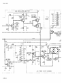
4-36. POWER SWITCH.
4-37. A simplified schematic diagram of the power
switching arrangement is shown in figure 4-11. The
power switch, S2, has four positions: OFF, AC,
BATTERY ON, and BATTERY CHARGE. In the AC
position, the instrument operates from the conventional line voltage: if a battery has been installed in
the instrument, a trickle charge is supplied to the
battery. In the BATTERY ON position, instrument
operation i s entirely dependent on the battery. In
the CHARGE position, -25 volts i s connected to the
battery for recharging: the Model 431B cannot be
operated during this time. Approximately 37 ma dc i s
applied to the battery during charge time.
/
n
I
-25V
CR2
FROM
CR3
-IBVDC(REG)
REGULATOR
CENTER
SD-S-177
Figure 4-10. Regulated Power Supply
I
JI
A
1'
+
d
S
2
pGq
Q
0
a-
2
- -piqp]pq
v
pFFF/
POWER
TRANSfORYER
R2
- 4 0 VOLT
RECTlflER
R3
I
-25 VOLT
RECTlf I E R
I
I
-
0
I
5
-IBV(REG)
REGULATOR
9
0
Z
-
OPTIONAL
BATTERY
+
T
Figure 4-11. Power Switch Arrangement
I.5V (UNREGI
Model 431B
Section V
Figure 5-1
Figure 5 -1. Cover Removal
Section V
Paragraphs 5 -1 to 5 -7
Model 431B
SECTION V
MAINTENANCE
5-1. I N T R O D U C T I O N .
5-2. This section includes instructions and information for the maintenance, troubleshooting and repair
of the Model 431B Power Meter.
5-3. The testing and repair of @ Model 486A and
478A thermistor mounts a r e discussed in the OperatingNotes for each instrument. Complex procedures
and special equipment a r e needed for some of these
operations. Therefore, if the trouble proves to be a
thermistor mount, contact an @field office for assistance. Except as stated in the Operating Note, DO NOT
ATTEMPT TO F Z PAIR THE THERMISTOR MOUNT.
the circuit board and removal of the meter. RANGE
POWER, o r MOUNT RES switch would require the
removal of the bottom cover and one, o r both, of the
side covers.
5-6. TOP COVER REMOVAL.
a. At the r e a r of the instrument, remove the two
screws which retain the cover.
b. Grasp the cover from the rear, slide it back 1/2
inch, then tilt forward edge of the cover
and
lift the cover from the instrument.
5-7.
5-4. C O V E R R E M O V A L A N D R E P L A C E M E N T .
5-5. Refer to figure 5-1 when removing instrument
covers. Removal of the top cover exposes the circuit
a r e a s shown in figure 5-2. Routine checksand adjustments can be ~ e r f o r m e dwithout the removal of other
covers. However, operations such a s soldering on
Table 5-1.
Instrument
Type
Use
TOP COVER REPLACEMENT.
a. Rest the cover flat on the cast guides projecting
inward near the top of each side frame (see @ ,
figure 5-1).
b. Slide the cover forward allowing i t s forward
edge to enter the groove in the front panel.
c. Replace the two cover retaining screws.
Test Equipment
Critical Specifications
Instrument
Recommended
DC voltmeter
DC voltage measurement
Calibration accuracy
check
Range: 0.5 to 50 volts dc
Accuracy:
0.2%
Resolution: three digit
@ 405BR/CR
Ohmmeter
Continuity & resistance
checks
Range: 1 ohm to 10 megohms
Accuracy: 5% of full scale
@ 410B
@ 412A
Precision
milliammeter o r
Power Meter
Calibrator
Calibration accuracy
check
Milliammeter
Accuracy: 0.1% of
full scale
Range: 0 to 30 ma
Sensitive Research
Instrument Corp
Model B, Bamilek
Calibrator
Current accuracy:
0.1%
Resistance accuracy:
0.2%
@ 8402A Power
Meter Calibrator
Milliammeter
Battery circuit check
Range: 3 to 60 ma dc
Accuracy: 5%
@ 412A
@4 2 8 A / ~
Oscilloscope o r
AC voltmeter
Power supply ripple
check
10 kc oscillatoramplifier check
10 kc amplifier check
10 kc amplifier null
adjust
Oscilloscope
Bandwidth: 100 kc
Accuracy: 5%
Input impedance:
1 megohm
Sensitivity: 1 mv/cm
@ 130B/C
@ 120B
Accuracy: 5%
Input impedance:
1 megohm
Range: 01 to 100 mv
@ 400~/H/L
AC voltmeter
.
@ 122A
@ 403A/B
Model 431B
Section V
Paragraphs 5-8 to 5-9
Table 5- 1. Test Equipment (Cont'd)
Instrument
Type
Instrument
Recommended
Critical Specifications
Use
DC Source o r
Power Meter
Calibrator
Calibration accuracy
check
Range: 0 to 220 vdc o r
Current Output: 0 to 20 ma
@711A, 712B
Power Supplies
8402A Power Meter
Calibrator
Thermistor Mount
Completion of test
circuit
See table 1-2 for list of suitable
mounts
$3 478A, 486A
Frequency
counter
10 kc oscillatoramplifier check
10 kc oscillator-amplifier frequency adjust
5 place readout
Min. input sensitivity: 4 v r m s
Max. frequency: greater than lOkc
Accuracy: better than 0.1%
($3 5212A
@ 55128
Variable
Transformer
Power supply adjustment
Range: 103 to 127 vac @ 7-1/2 amp
206 to 254 vac @ 4 amp
Voltmeter range: 100 to 127 vac
200 to 254 vac
Voltmeter accuracy: i 1 volt
General Radio type
W lOMT3A
Soldering Jron
& Tips
Repair
Wattage rating: 50 watts
Min tip temp: 800°F
Tip size O.D. : 1/16" to 3/32
Ungar #776 soldering iron handle
Ungar #PL333
tiplet
Ungar #854 Cup tip
Resistor
Charging checks
Value: 780 52
Accuracy: 1%
Wattage: 3 watts
Dale
Type RS-2
Resistor
Charging checks
Value: 7500 52
Accuracy: * 1%
Wattage: 2 watts
Electra MF2, T-0
Decade
Resistance
Divider
Zero and vernier
control adjustment
Full scale accuracy adj
Range: 5 0 8 to 50K 52
Multiple: 10 8
Accuracy: 1%per decade
GR1432P Decade
Resistance Box
Precision
Resistor
Zero and vernier control
adjustment
Value: 1000 8
Accuracy: + 0.1%
Wattage: 0.25 watts
Ultronex
Type 205A
Decade
Capacitors
Oscillator frequency
adjustment
Coarse null adjustment
Range: 10 to 1000 pf
Capacitance per step: .0001 pfd
Accuracy: . I % per decade
General Radio
Type 1419-B
5-8.
BOTTOM COVER REMOVAL.
5-9.
@521C o r E
BOTTOM COVER REPLACEMENT.
a. Set the tilt stand a s shown in figure 5-1.
a. Set the tilt stand a s shown in figure 5-1.
b. Remove the two retaining screws a t the r e a r of
the cover.
b. Rest the bottom cover flat on the cast guides
projecting inward near the bottom of each side frame
(see @ , figure 5-1).
c. Slide the cover rearward f a r enough to free i t s
forward edge from the front foot assembly.
c. Slide the cover forward on the guides s o that
the formed portion at the r e a r of the cover slides
over the two short pro'ections at the r e a r corner of
each side frame (see
, figure 5-1).
d. Tilt the forward edge of the cover upward and
lift the cover from the instrument.
d. Replace the two retaining screws and the rear
foot assembly.
6
Model 431B
Section V
Paragraphs 5-10 to 5-18
5-16. Table 5-2, Troubleshooting, and the following
detailed tests a r e given to aid in correcting trouble
within the Model 431B. To
localizing of trouble
easier, the 431B circuitry is divided into five sections;
the power supply, the 10 kc oscillator-amplifier (including the rf bridge), the 10 kc amplifier (including
the metering bridge), the dc metering and feedback
amplifiers, and the squaring circuit. Tests a r e given
for each of these sections.
5-10. SIDE COVER REMOVAL.
5-11. The side covers cannot be removed untilthe top
and bottom covers a r e off (see paragraphs 5-6and 5-8).
Each side cover is held in place by four screws retained
by nuts which are not fastened to the side frames.
Note
Replace side covers before replacing either
the top o r the bottom cover.
5-17. THE POWER SUPPLY.
5-12. TEST EQUIPMENT.
5-13. Any instruments which satisfy the specifications
of table 5-1 can be used for the tests described in this
maintenance section.
5-14. TROUBLESHOOTING.
5-15. The first step in troubleshootingthe Model 431B
Power Meter should be isolation of trouble to the
thermistor mount and thermistor mount cable o r to the
power meter itself. The thermistor match check in
the maintenance section of the @ Operating Note pertaining to the thermistor mount in use will indicate a
defective thermistor o r thermistors. A simple ohmmeter continuity check and inspection of the thermistor
mount cable and i t s connectors can be used to prove
the cable.
Table 5 -2.
5-18. The dc test point voltages shown on the power
supply schematic diagram, with two exceptions, apply
to instruments operated from either a c o r battervprimary power. voltage limits shown a t C l and C2-apply
only to instruments operated from a c primary power.
Refer to figure 5-2, Top View, for component location.
a. Connect Model 431B to a variable line transformer
and s e t transformer for 115 vac (or 230 vac).
b. Connect a dc voltmeter (see table 5-1 for voltmeter requirements) between the negative terminal of
C6 and Model 431B ground. The voltage here should
be -18 vdc; adjust with potentiometer R13.
c. With the voltmeter connected a s above, test the
regulation of the power supply (for instruments
-
Troubleshooting
Possible Cause
Trouble Indication
Null impossible
Thermistor mount
Thermistor mount cable
MOUNT RES switch
TI02
Meter does not indicate, does not zero but does null
Q106
Meter pointer drifts during readings
Thermistor mount
Q106, Q107
Thermistor mount in unstable thermal environment
R F source unstable
DC calibration/substitution source unstable
Oscillator -amplifier
10 kc amplifier
Interference from external 10 kc signal
Rotation of the ZERO o r VERNIER control results
in erratic movement of the meter pointer on the
- 0 1 MW range
ZERO o r VERNIER potentiometer
Movement of the thermistor mount cable causes abrupt flicker of the meter pointer on the. 01 MW range
Thermistor mount
Thermistor mount cable
Meter pointer stays down scale
TI02
Thermistor mount
Thermistor mount cable
Power supply
Meter
RECORDER jack
Q106
C102, ClOl
10 kc amplifier
Model 431B
Section V
Paragraphs 5-19 to 5-24
Table 5 -2.
Troubleshooting (Cont'd)
Possible Cause
Trouble Indication
Meter pointer stays up scale
TI02
Oscillator failure
Thermistor mount cable
Large unbalance in the metering bridge
C105
C104
10 kc amplifier failure
Calibration inaccurate, all power ranges
Thermistor mount in strong rf field
Interference from s t r a y 10 kc signal
Thermistor mount
Meter not mechanically zero-set
Meter
MOUNT RES switch
Power supply
Battery
10 kc amplifier
Resistor, collector QlOl
Q107, Q106
Q102
Calibration inaccuracy, NOT a l l power ranges
Resistors emitter Q107
Q106
10 kc amplifier
Zero setting does not c a r r y over from range to
range within specification
Q106
R141
Q104
operated from a c primary power) by varying the line
voltage +lo% about the nominal 115 o r 230vac. T h e r e
should be no perceptible variation of the -18 vdc.
d. If -18 volts cannot be obtained by adjustment of
R13, o r if regulation is not satisfactory, proceed with
the following t e s t to determine the causes:
(1) Use a dc voltmeter (see table 5-1) to check the
a c voltage limits a t the points listed in table 5-3.
See figure 5-2, top view, for component location. A l l voltages a r e measured with reference
to the Model 431B ground.
(2) Check ripple voltages (ac operation), using an
a c voltmeter o r oscilloscope, a t the points
listed in table 5-4. Table 5-1 gives requirements for the voltmeter o r oscilloscope.
5-19. If the power meter does not function normally
(e.g., pointer driven to i t s limits, nopower indication)
and power supply regulation isunsatisfactory, another
circuit area, such a t the 10 kc oscillator-amplifier
o r 10 kc amplifier, could be the cause.
5-20. A -18 vdc supply which is s e t high o r low
causes calibration inaccuracy of the Model 431B.
5-21. 10-KC OSCILLATOR-AMP LIFIER CHECK.
5-22. T e s t s of the oscillator-amplifier should be made
according to the step sequence in which they appear
below. A dc voltmeter, an a c voltmeter o r oscilloscope and a frequency counter a r e needed for the
tests (see table 5-1 for test instrument specifications).
Figure 5-2, Top View, shows component location.
5-23. STEP 1.
a. Connect the oscilloscope between the positive
lead of C125 and ground, check the 10 kc oscillatoramplifier output amplitude and waveform. Output
amplitude, with a 200 ohm thermistor mount connected to the Model 431B, should be 15 vac i20%
peak-to-peak.
If a 100-ohm mount is used, the
amplitude should be 8 vac i20% peak-to-peak. The
waveform must be sinusoidal with only slight crossover distortion (caused by QllO and Q111).
b. Check the frequency of the oscillator-amplifier.
If a Model 478A thermistor mount is used, terminate
the rf input to the mount in 50 ohms. A Model 486A
thermistor mount does not require termination. Connect the frequency counter between the positive lead
of C125 and ground. With Model 478A thermistor
mount connected to the Model 431B, the oscillatoramplifier frequency should be 9750-10,000 cps. With
a Model 486A thermistor mount connected, the frequency should be 10 kc i 5 0 cps.
5-24. STEP 2.
a. Connect the oscilloscope between the base of
Q108 and ground; observe the amplitude of the feedback signal to the oscillator-amplifier. It must be
l e s s than 12 mv peak-to-peak: if not, 10 kc oscillatoramplifier gain is incorrect. The cause couldbe Q108,
Q109, C124, L101, L105 o r T101. IfTlOl is the cause
of trouble u s e a special soldering tip to remove i t
from etched circuit board (see table 5-1).
Section V
Tables 5-3, 5-4, 5-5
Model 431B
Table 5 -3.
Power Supply DC Voltage Checks
DC Voltage Limits
Test Point
Voltage Out of Limits, Check
-38
to -43
a c line voltage, CR1, CR4, C1
Minus end of C2
-24
to-27
a c line voltage, CR2, CR3, C2, battery
Anode of CR8
-10.7 to -12.3
Minus end of C1
CR8
- 6.0 to - 7.5
Anode of CR7
CR7, @
Minus end of C6
-18
R13, (3,(22
Base of Q1
-18.3 to -18.6
Anode of CR9
-24.0 to -25.6
Q1, Q3, Q2, CR7
CR9, POWER switch
Plus end of C1
+ 1.4 to +1.5
CR5, CR6
Table 5-4.
Power Supply Ripple Checks
AC Voltage Limits
Test Point
Voltage Out of Limits, Check
Peak-to-Peak
R. M. S.
Minus end of C1
1.8 v max.
5vmax.
cR1, CR4, C1
Minus end of C2
1.1 v max.
3vmax.
CR2, CR3, C2, C6, Q13
Minus end of C6
10.6 mv max.
30 mv max.
Q1 to Q5, CR7, CR15, C2, C6
Table 5-5. 10 KC Oscillator-Amplifier DC Voltage Checks
Test Point
DC Voltage Limits
-18
Collector of QllO
Power Supply
Emitter of Q109
-10.0 to -14.0
Minus end of C12 1
-
5.0to
Q108, Q109, C122, C121
- 6.5
Table 5-6.
Test Point
Voltage Out of Limits, Check
C121, Q108, R153
10 KC Amplifier DC Voltage Checks
DC Voltage Limits
Voltage Out of Limits, Check
Emitter of QlOl
-1.5 to -2.5
Collector of QlOl
-4.5 to -6.0
C112, R116, R115, C110, QlOl
Q101, C113, R117 to R124
Positive end of C116*
-3.5 to -4.5
Q103, R132, Q102, C115
* Short base to emitter of
I
QlOl
Table 5-7.
Test Point
Cathode CR113
DC Voltages in Squaring Circuit
DC Voltage Limits
+ 10.30 to + 10.46
+ 8.50 to + 9.64
Voltage Out of Limits, Check
CR113, R167, R173
Cathode CR112
Cathode C R l l l
+
6 . 4 1 t o + 6.51
CR112, R174, R168
CR111, R175, R169
Cathode CRllO
+ 4.39 t o + 4.47
CR110, R176, R170
Cathode CR109
+ 2 . 4 8 t o + 2.52
CRlO9, R177, R171
Cathode a 1 0 8
0
CR108, CR109 to a 1 1 3
Section V
Paragraphs 5-25
POWER
SUPPLY
R179
DC METERING AND
FEEDBACK CIRCUITS
R13
-18V REG. AOJ.
BATTERY
SYNCHRONOUS
UP-S-1149
i
Figure 5-2. Top View
b. Using the dc voltmeter, make dc measurements
at the p o w listed in table 5-5. Xf ttte presence of
10 kc signal interleres with the dc measurements, the
10 kc oscillator can be disabled, witbout appreciably
affecting the dc voltages, by grounding the collector
of Q109. DC voltages are measured with reference
to the Model 4S1B ground.
5-25. STE2 3.
If there is no 10 kc output from the
oscillator-amplifier proceed as f0lbw8:
a, Maconnect the thermistor mount.
b. Maconnect the poeitlve lead of C125 from the
circuit board.
c. Make a direct connection between the positive
lead of C125 and bridge side of C120 (terminal 35 on
the underside of the circuit board).
d. Using the oscilloscope, monitor the ou@utof the
oscillator-amplifier.
If oscillation is present, the
mebring and rf bridges should be examinedfor defect.
The waveform of the oscillation under this condition
may show limiting.
Section V
Paragraphs 5-26 to 5-43
Model 431B
5-26. If component replacement is required a s a
result of the foregoing tests, note the following:
a. After replacement of QllO o r Q111, check the
amplitude of the 10 kc oscillator-amplifier output
(paragraph 5-23a).
b. If Q108 o r Q109 has been replaced, check the output frequency of the oscillator-amplifier (para. 5-23b).
5-36. The squaring circuit i s tested under two conditions: (1) when all diodes a r e conducting, and (2) when
no diodes a r e conducting. Both conditions should be
used whenever the squaring circuit is tested.
5-37. A digital voltmeter (see table 5-1 for specifications) is recommended for the following measurements.
c. After replacement of L105 o r C124, readjustment
of the oscillator frequency could be necessary. See
paragraph 5-58 for this procedure.
5-38. DIODES CONDUCTING. The following procedure measures the forward voltage drop of each
diode in the squaring circuit.
5-27. 10 KC AMPLIFIER CHECK.
a. Set the Model 431B RANGE switch to 1 MW, and
adjust the ZERO and VERNIER controls for exact full
scale deflection of the meter pointer.
5-28. A dc voltmeter and oscilloscope a r e needed for
checking the 10 kc amplifier. Table 5-1, T e s t Equipment, gives equipment requirements. Refer to figure
5-2, Top View, for component location.
5-29. Table 5-6 lists dc voltage check points and
possible causes for deviations from the given limits.
All voltages a r e referenced to the Model 431B ground.
If the presence of a 10-kc signal interferes with dc
measurement, ground the center tap of L102.
5-30. Calibration inaccuracy, common to all power
ranges, can be caused by the 10 kc amplifier. In
particular, an out-of-tolerance resistor in the collector
of QlOl o r a defect in the Q102 stage, which results
in improper gain, will produce calibration e r r o r .
5-31. An open signal path o r very low gain in the 10-kc
amplifier can drive the meter pointer to its downscale
limit. For signal tracing, the 10 kc e r r o r signal from
the metering bridge can be used, o r C110 can be disconnected and used a s a means of injecting a substitute
10 kc test signal.
b. Disconnect the grounding link a t the digital voltmeter input, and measure the voltage drop across the
individual diodes of the squaring circuit. The requirement is 0.4 to 0.5 vdc.
5-39. DIODES OFF. The test points listed in table
5-7 a r e the midpoints of five two-resistor voltage
dividers connected between -18 vdc and ground. This
check verifles that each diode is properly backbiased.
a. Adjust the Model 431B ZERO control for a belowzero deflection of the meter pointer.
b. Connect the voltmeter (ungrounded input) between the regulated -18 vdc supply and the test points
listed in table 5-7. The voltmeter readings should be
within the limits specified in the table.
Note
A special soldering tip is required to replace
transformer T102. Refer to table 5-1 forthe
type of soldering tip to be used.
5-32. METERING AND FEEDBACK CIRCUIT.
5-33. Before performing this procedure refer to paragraphs 5-69 and 5-70 and check values ofR141and
R179. The differential amplifier (Q104 and Q105), the
feedback current squared generator (Q106), the feedback current generator (Q107), and the squaring circuit
comprise the metering and feedback circuit. See figure
5-2, top view, for component location.
Note
Transistors Q106 and Q107 a r e selected for
optimum calibration accuracy. If Q106 o r
Q107 is replaced, check calibrationaccuracy
using procedure given in paragraph 5-76 or
5-78. It may be necessary to t r y several
transistors to get proper calibration
accuracy.
5-34. SQUARING CIRCUIT CHECKS.
5-35. A check of the squaring circuit is advisable if
full scale o r tracking accuracy of the Mode1 431B does
not meet specifications. The squaring circuit includes
CR108 through CR113 and R167 through R177. Figure
5-2, Top View, shows component location.
5-40. BATTERY A N D C H A R G I N G CHECKS.
5-41. The information and procedures which follow
pertain to power meters having the optional nickel
cadmium battery. The battery is an assembly of 20
individual, permanently sealed cells connected in
series.
At full charge, battery terminal voltage
should be 27 volts *lvolt. An inoperative cell reduces
terminal voltage by approximately 1.3 volts.
5-42. BATTERY CHECK.
5-43. BATTERY VOLTAGE.
A dc voltmeter is
needed for this test.
See table 5-1 for voltmeter
requirements.
a. Make s u r e that the Model 431B i s disconnected
from the a c line. Connect the dc voltmeter between
the BATTERY - and BATTERY + terminals on the
etched circuit board.
b. Set the POWER switch to BATTERY ON and
observe the voltmeter reading. Battery voltage should
be -24 to -27 volts. If it is not, and the battery has
been charged, check the charging circuits and the
current drain imposed by the Model 431Bcircuitry.
If the state of charge of the battery is uncertain,
allow a 48-hour recharge, then recheck the battery
voltage. Check the charging circuits if the battery
voltage is still not within 27 *1 volt.
Model 431B
Section V
Paragraphs 5-44 to 5-55
5-44. BATTERY CURRENT DRAIN. The current
supplied by the battery to the Model 431B circuitry
should be checked i f the battery does not seem to
maintain a charge. A clip-on or series-connected
current meter (see table 5-1) is required for the
following procedure.
5-50. BATTERY WARRANTY.
5-51. The warranty, appearing on the inside of the
rear cover of this manual, also applies to the accessory battery (option 01). Within the warranty period,
the battery may be returned to @ Customer Service
for repair or replacement.
a. Check that the Model 431B is disconnected from
the ac Line.
b. Connect the current meter to monitor the current
in one of the leads between the battery terminals and
the BATTERY and BATTERY + terminals on the
circuit board.
-
c. Set the POWER switch to BATTERY ON and
observe the reading on the current meter; it should
read 40 to 53 ma.
5-45. CHARGING CHECKS.
5-46. The following procedures test the recharge and
trickle charge capability of the Model 431B. A direct
current meter (see table 5-I), a 7500 ohm*l%, 2 watt
resistor and a 780 ohm *l%,3 watt resistor a r e required for these tests. The battery i s disconnected
from the BATTERY - and BATTERY + circuit board
terminals during both tests.
5-47. TRICKLE CHARGE CURRENT. The following
procedure is used to check the trickle charge current
applied to the battery whenthe power meter is operated
from ac primary power.
a. Connect the 7500 ohm 2-watt resistor between
the BATTERY - and BATTERY + terminals of the
circuit board.
b. Connect the current meter to monitor the current
through the resistor.
c. Connect the Model 431B to the ac line, set the
POWER switch to AC, and observe the reading of the
current meter. Trickle-charge current should be 3.2
to 4.8 ma.
5-48. CHARGE CURRENT. The following procedure
checks the current supplied for recharging the battery.
a. Connect the 780 ohm 3-watt resistor between the
BATTERY - and BATTERY + terminals of the circuit
board.
b. Connect the current meter to monitor current
through the resistor.
5 - 5 2 . REPAIR.
5-53. The etched circuit board used inthe Mode1431B
is of the plated-through type which consists of a base
board and conductor. The board does not include
funneled eyelets. The conductor material i s plated to
the wall of the holes; thus the conductor is effectively
extended into the hole. This type of board can be
soldered from either the conductor o r component side
of the board with equally good results. The rules given
below should be followed when repairing a platedthrough type etched circuit board.
a. Avoid applying excessive heat when soldering on
the circuit board.
b. To remove a damaged component, clip component
leads near the component; then apply heat and remove
each lead with a straight upward motion.
c. Use a special tool to remove components having
multiple connections, such a s potentiometers, transformers, etc. Refer to table 5-1 for type of soldering
tip required.
d. Use a toothpick to free hole of solder before installing a new component.
5-54. M E C H A N I C A L A D J U S T M E N T O F
METER Z E R O .
5-55. When meter is properly zero-set, pointer rests
over the zero calibration mark on the meter scale
when the instrument i s 1)at normal operating temperature, 2) in its normal operating position, and 3)
turned off. Zero-set a s follows to obtain best accuracy and mechanical stability:
a. Allow the instrument to operate for at least 20
minutes; this allows the meter movement to reach
normal operating temperature.
b. Turn instrument off and allow 30 seconds for all
capacitors to discharge.
c. Connect the Model 431B to the ac line, set the
POWER switch to BATTERY CHARGE, and observe
the reading of the current meter. Charging current
should be 27 to 40 ma.
c. Rotate mechanical zero adjustment screw until
pointer is on zero. Reverse direction of adjustment
screw approximately 3" in order to free adjustment
screw from meter movement. If the pointer moves
while freeing the adjustment screw, this step must
be repeated.
5-49. A battery which will not assume rated terminal
voltage with proper charging current may have adefective cell o r cells. In such cases the battery must
be replaced (see section VI Table of Replaceable
Parts).
Note
Use of the parallax-eliminating mirror on
the meter scale increases the accuracy of
the mechanical zero-set.
Section V
Paragraphs 5-56 to 5-68
5-56. ADJUSTMENTS.
5-57. POWER SUPPLY ADJUSTMENT.
a. Connect a dc voltmeter (see table 5-1 for required specifications) between the negative end of
C6 and Model 431B ground.
b. Adjust -18 v REG. ADJ., R13, for -18 vdc.
c. Vary line voltage from 103 to 127 vac (207 to 253
vac): -18 vdc should not vary perceptibly.
5-58. OSCILLATOR FREQUENCY ADJUSTMENT.
5-59. If both 100 and 200 ohm thermistor mounts a r e
tobeused interchangeably with the Model 431B, the
frequency of the 10 kc oscillator-amplifier should be
adjusted in the following sequence: the 200 ohm mount
procedure, paragraph 5-61, then the 100 ohm mount
procedure, paragraph 5-62. If only one type of mount
will be used with the power meter only the appropriate
procedure is required.
5-60. An oscilloscope and frequency counter a r e
needed for these adjustments. See table 5-1, Test
Equipment for requirement. A plastic alignment tool
should be used for the adjustment of LlOl to avoid
core damage.
5-61. 200 OHM MOUNT. The following procedure
adjusts the 10 kc oscillator frequency when a 200 ohm
thermistor mount is connected to the Model 431B.
a. Connect the 200 St thermistor mount and cable to
the Model 431B; set the MOUNT RES switch to 200 52.
b. Connect the frequency counter between the plus
end of C125 and ground; adjust L101 to give a frequency
of 10,150 cps.
c. Connect the oscilloscope to the base of Q108 and
observe the feedback signal amplitude. It should not
exceed 12 mv peak-to-peak.
5-62. 100 OHM MOUNT. The following procedure
adjusts the 10 kc oscillator frequency when a 100 ohm
thermistor mount is connected to the Model 431B.
a. Connect the 100 ohm thermistor mount and cable
to the Model 431B, and set MOUNT RES t o 100 52.
b. Connect the frequency counter between the positive end of C125 and ground. The frequency should be
10 KC rt50 cps. If i t i s not, proceed with step c.
c. Substitute values of capacitance for C l O l until
the frequency is within the limits of step b.
Note
A decade capacitance box can be used to determine proper value of capacitance that must
be used (see table 5-1).
5- 63. COARSE NULL ADJUSTMENT.
5-64. If both 100 and 200 ohm thermistor mounts a r e
to be used interchangeably with the Model 431B, the
coarse null adjustment should be made in the following
sequence; the procedure in paragraph 5-67 first, and
then the procedure in paragraph 5-68.
5-65. If only a 200 ohmthermistor mount is to be used
with the power meter, follow the procedure of paragraph 5-68. When only a 100 ohm thermistor mount
is to be used, the procedure of paragraph 5-67 is
sufficient.
5-66. An oscilloscope o r ac vtvm is needed for these
adjustments. See table 5-1, T e s t Equipment, for
requirements. A plastic alignment tool should be
used for the adjustment of L102 toavoid core damage.
5-67; 100 OHM MOUNT. The following procedure is
used to make coarse adjustment of the null when a 100
ohm thermistor mount i s connected to the Model 431B.
a. Set MOUNT RES to 100 St.
b. Observe the arrangement and travel of null
capacitor C103, then mechanically center C103.
c. Connect the oscilloscope o r a c vtvm between
ground and the base of Q103.
d. Switch the Model 431B on and s e t RANGE to
10 MW.
e. Adjust the ZERO control to maintain a meter
indication of less than 5% of full scale on the Model
431B while adjusting L102 for a minimum indication
on the oscilloscope o r vtvm.
f. Set RANGE to .01 MW and repeat step e, this
time maintaining an on-scale meter indication on the
Model 431B.
g. Move the oscilloscope o r vtvm connection from
the base of Q103 to the lead of R138 nearest T103.
h. Adjust null capacitor C103 to minimize oscilloscope o r vtvm indication. Minimum indication should
occur with the capacitor near the center of its range.
Note: A decade capacitance box can be used
to determine the value of capacitance to be
added (refer to table 5-1).
i. SetModel 431B RANGE switch to NULL. Adjust
the null capacitor, C103, for a minimum indication on
the Model 431B meter. Minimum indication should
occur a t l e s s than 4% of full scale and C103 should be
near its mid-range.
Note: When only a
-
100-ohm thermistor mount
will be used with the Mode1 431B, the value
of C104 may be changed to obtainthe null r e quirements specified above.
5-68. 200 OHM. The following procedure i s used to
make coarse null adjustment when a 200-ohm therm
istor mount is connected to the Model 4318.
-
a. Set MOUNT RES to 200 Q
.
Section V
Paragraphs 5-69 to 5-74
b. Set RANGE to .O1 MW.
c. Connect the oscilloscope or vtvm between ground
and the lead of R138 nearest T103.
d. Mechanically center the null capacitor, C103, by
observing i t s rotor plates.
Model 431B
b. Set Model 431B RANGE to 10 MW; set Model
8402A RANGE (MW) to 10 MW, and FUNCTION to CAL.
c. Adjust the Model 431B ZERO and VERNIER
controls for a zero indication on the meter.
e. Using the ZERO andVERNIER controls, maintain
an on-scale indication on the Model 431B meter while
substituting values for C105 to obtain a minimum
indication on the oscilloscope o r vtvm.
d. Set Model 840211 OUTPUT CURRENT to ON;
connect decade box across terminals of R179. Adjust
decade box for a reading of exactly 10 mw on 431B
panel meter. Switch Model 8402A to 8 mw, 6 mw,
4 mw, then 2 mw. Model 431B panel meter should
track within i2% of full scale (see table 5-8). Disconnect decade box.
f. Adjust C103, the null capacitor, to improve the
minimum indication on the oscilloscope o r vtvm. The
null capacitor should be near mid-range.
e. Set Model 8402A OUTPUT CURRENT to OFF.
Note
A decade capacitance box can be used to determine the value of capacitance to be added
(see table 5-1).
g. Set RANGE to NULL. The Model 431B meter
deflection should be l e s s than 4% of full scale. If i t is
not, increase the value of C104 in approximately 50 pf
increments to a maximum value of 500 pf. If 100 and
200 ohm thermistor mounts a r e to be used, repeat the
null procedure for 100 ohm mounts (paragraph 5-67)
after each increase in capacitance of C104.
f. Set Model 431B RANGE to 3 MW; set Model
8402A RANGE (MW)to 3 MW.
g. Reset Model 431B VERNIER to zero the meter,
if necessary.
h. Set Mode1 8402A OUTPUT CURRENT to ON;
note and record the Model 431B percent -of -powerreading e r r o r (1.7%/division on 0-3 meter scale).
i. Repeat steps b through h for alI Model 431B
RANGE positions.
j. Connect a decade resistance box across R179
(see figure 5-2).
5-69. ZERO AND VERNIER CONTROL ADJUSTMENT.
a. Connect a dc digital voltmeter (see table 5-1) a t
the Model 431B RECORDER jack.
Use a special
telephone-plug-to-dual-banana-plug cable assembly
terminated with a 1000-ohm i0.1% 0.25-watt wirewound resistor.
b. Set Model 431B RANGE to .O1 MW, and adjust
Model 431B ZERO and VERNIER controls for zero
meter reading on the Model 431B.
c. Set Model 431B RANGE to 10 MW.
d. Connect a decade resistance box across R141
(see figure 5-2), and adjust to obtain zero indication
on Model 431B Power Meter.
e. Note amount of resistance required from resistance box to obtain zero indication.
f. Remove the decade resistance box, and replace
with resistor of value noted in step e.
g. Check the Model 431B range-to-range zero drift
by 1) setting Model 431B RANGE to .01 MW, and readjusting i t s VERNIER for zero meter reading, 2)
switching the Model 431B through its complete range
while observing the digital dc voltmeter reading. Test
limits: digital dc voltmeter reading must not exceed
1 5 mv (10.005V) on any Model 431B range.
5-70. FULL SCALE ACCURACY ADJUSTMENT.
a. Connect a @ Model 8402A (see table 5-1) at the
Model 431B POWER METER terminals. Check that
Model 8402A OUTPUT CURRENT is off.
k. Select the resistance value which equalizes the
magnitude of the largest positive and negative percent
error.
m. Remove the decade resistance box and replace
with a resistor of the value selected in step k.
n. Check all Model 431B RANGE positions. Test
limits: the Model 431B full-scale p o w e r - r e a d i n g
e r r o r must not exceed 3% a t ambient temperatures of
20°C to 35°C on all range positions (refer totable 5-8).
5-71. P E R F O R M A N C E CHECK.
5-72. The tests described below which verify that the
Model 431B meets specifications, use only panel controls and connectors. These tests can beused for incoming quality control, for routine preventive maintenance, and after repair. A thermistor mount must be
connected to the Model 431B for the performance
checks, though no rf power will be applied.
Note
If there is possibility of rf pick-up, the thermistor mount should be appropriately
shielded.
5-73. Check the mechanical zero-set of the Model
431B meter according to paragraph 5-54.
5-74. ZERO CARRY-OVER CHECK.
a. Set Model 431B RANGE to . O 1 MW.
Section V
Paragraphs 5-75 to 5-80
Model 431B
b. Adjust ZERO and VERNIER controls to set the
meter pointer over the zero calibration mark.
c. Rotate RANGE through its .03, . 1, .3, 1, 3, and
10 MW positions, observing the accuracy of the zero
setting at each position. The zero must carry over
from range to range within fO. 5% of full scale.
5-75. CALIBRATION AND RANGE TRACKING
ACCURACY.
5-76. Calibration and range tracking accuracy is
verified by dc substitution. Briefly, dc substitution
involves 1) applying enough direct current at the DC
CALIBRATION & SUBSTITUTION terminals to obtain
the desired meter indication 2) accurately determining
the applied current and 3) calculating the dc power
applied. The difference between the substituted dc
power and the meter indication it produced is the calibration error. The @ Model 8402A Power Meter
Calibrator, or other means of producing accurate
direct currents, is used a s the substitution source.
Table 5-8.
Tracking
10 mw
8
6
4
2
3 mw
1 mw
.3 mw
1 mw
.03 mw
. O l mw
5-78. Refer to the Operating and Service Manual of
the Power Meter Calibrator for correct testprocedure.
5-79. ALTERNATE METHOD FOR CHECKING CALIBRATION AND RANGE TRACKING ACCURACY. The
calibration and range tracking accuracy of the Model
431B can be checked by dc substitution using the equipment and connections shown in figure 3-3.
5-80. Using the data in table 5-8 the full scale calibration accuracy of each range and the tracking
accuracy of the 10 mw range can be tested.
Data for Calibration, Tracking Accuracy Check
Substitution Current (Idc)
Test Point
Full
Scale
5-77. CALIBRATION AND TRACKING ACCURACY
TEST USING THE @ MODEL 8402A POWER METER
CALIBRATOR. The Model 8402A Power Meter Calibrator provides constant currents sufficient to cause
full scale meter indication on each of the Model 431B
power ranges. It also has provision for checking the
tracking accuracy of the Model 431B on the 10 mw
range.
mw
mw
mw
mw
Mount Res
100 2
20.00 ma
17.89
15.49
12.65
8.94
10.95
6.32 ,
3.46
2.00
1.10
0.632
~ o U n Re
t s
200 51
14.14 ma
12.65
10.95
8.94
6.32
7.75
4.47
2.45
1.41
0.775
0.447
Model 431B Meter Reads
9.7
7.8
5.8
3.8
1.8
2.91
0.97
0.291
0.097
0.0291
0.0097
to10.3 mw
to 8.2 mw
to 6.2 mw
to 4.2 mw
to 2 . 2 m w
to 3.09 mw
to 1.03 mw
to 0.309 mw
to 0.103 mw
to 0.0309 mw
to 0.0103 mw
Model 43 1B
Section V
Figure 5 -3
RF SHIELD
-------- ----------
WAVEGUIDE
----1
THERMAL
CONDUCTING
:g
I
1 CABLE
TO
3
-1
4
2
0
5
6
I
DETECTION
THERMISTOR
-
-
-
I
COMPENSATION
THERMISTOR
1
I
I
I
I
-------------,--,J
WAVEGUIDE THERMISTOR
MOUNT
@ 486A
II
SIOIO--{
piGEq :
II
I
I
I
RF SHIELD
NOTES:
o = CONNECTION BETWEEN PIN 5 ON JlOl
AND TERM 4 ON ASSY 101 IN STANDARD 431B B. OPTION 10;
I/
I\
,
L103
2.5MH
I
I
PAGE I O r
2
Figure 5-3.
I
P/O a 0 1
--
Power Meter Assembly
--
--
-- -
Model 431B
--
I
I
--
--
--
PI0 _AIOL
IOKC OSCILLATOR-AMPLIFIER
-18V
REG
\t
A
/
"
/$1
EMITTER
FOLLOWER
0110/0111
I
-18'4
FEEDBACK CURE
1
I
AlOl POWER
-
-
--
METER ASSEMBLY
--
--
-
Section V
Figure 5-3
3
FEEDBACK CURRENT
GENERATOR
Q107
1854-0003
NOTES:
14
ONOUS DETECTOR7
I. DC VOLTAGE UMITS GIVEN AT
; b - I E V REG
R138
1500
VARIOUS POINTS THRU
CIRCUIT.
A THERMISTOR MOUNT I S
CONNECTED TO T H E 4 3 1 8
FOR THESE MEASUREMENTS.
REFERENCE DESIGNATORS
!t
RI~I*
39 K
>LC117
I
I
R142
1200
4)
C118
;,
~OUF--+
CR106
-
-
-1
DIFFERENTIAL
AMPLIFIER
I
I
-
AlOl
CIOI -106, 110 I 2 5
CRIOI- 113
5101. 102. 103
LIOI I 0 5
M 101
0101-111
R 101-103. 1 0 5 - 111,113-144.
150-155. 160- 181
s101.102
TI01 I 0 4
2.
& CHASSIS GROUND
3.
CIRCUIT EOARD COMMON
4. A L L VALUES I N OHMS AND
PICOFARADS. UNLESS
OTHERWISE INDICATED.
5.
-
FRONT PANEL
ENGRAVING
r---7
.I
UNASSIGNED: R112
6.
7.
---
REAR PANEL
ENGRAVING
0 ROTARY
-
SWITCH OR
POTENTIOMETER
m m
DC
IOKC
IOKC ERROR SIGNAL
8. 3C VALUE SELECTED AT FACTORY;
AVERAGE VALUE SHOWN
9
0 VOLTAGE MEASURED WITH
10.
@ TEST
RESPECT TO -18V REG.
POINT
COPYRIGHT 1962 BY NEWLETT- PACKARD COMPANY
4>18-PWm.
M E T E R - 10118
Figure 5-3.
Power Meter Assembly
PI0
A l O l !O_WER
7
I
METER AssY
--
--
+ 1.5'4
--
- -
--
--
--
UNREG I T 0 Rl43 AND R l 7 e l
3.
+
C H A S S I S GROUND
F R O N T PANEL
ENGRAVING
4'
r
COPYRIGHT 1902 B Y HEWLETT-PACKARD
'?
9
zw-
S-PO.".
Figure 5-4.
COMPANY
22#<bC'
Power Supply
1
-----
7
REAR PANEL
ENGRAVING
5.
@
SCREWDRIVER ADJUSTMENT
6.
0
ROTIRY SWITCH
7.
@
TEST POINT
Section VI
Paragraphs 6-1 to 6-7
Model 431B
S E C T I O N V1
REPLACEABLE P A R T S
6-3. Miscellaneous p a r t s not indexed in Table 6-1
a r e listed a t the end of the table.
6-1. INTRODUCTION.
6-2. This section contains information for ordering
replacement parts. Table 6-1 l i s t s p a r t s in alphanumerical order of their reference designators and
indicates the description and 6stock n u i b e r of each
part, together with any applicable notes. Table 6-2
lists p a r t s in alpha-numerical order of t h e i r &, stock
numbers and provides the following information on
each part:
a. Description of the p a r t (see l i s t of abbreviations
below).
b. Typical manufacturer of the p a r t in a five-digit
code; s e e l i s t of manufacturers in appendix.
c. Manufacturer's stock number.
d. Total quantity used in the instrument (TQ column).
6-4. ORDERING INFORMATION.
6-5. To o r d e r a replacement part, address order o r
inquiry to your nearest Hewlett-Packard field office.
Specify the following informati011for each part:
6-6.
a. Model and complete s e r i a l nutuber of instrument.
b. Hewlett-Packard stock number.
c . Circuit reference designator.
d. Description.
6-7. T o o r d e r a part not listed i n tables 6-1 and6-2,
give a complete description of the part and include i t s
function and location.
REFERENCE DESIGNATORS
A
B
C
CR
DL
DS
E
= assembly
F
motor
=capacitor
= diode
= delay line
= device signaling (lamp)
= misc electronic part
FL
= fuse
= filter
J
=
K
= relay
L
M
MP
=
=
jack
inductor
= meter
= mechanical part
P
Q
= plug
= transistor
R
= resistor
RT
S
T
= thermistor
= switch
= transformer
vacuum tube, neon
bulb, photocell, etc.
W
=cable
X
= socket
XF = Iuseholder
XDS = lampholder
Z
= network
V
=
ABBREVIATIONS
A
= amperes
= bandpass
BP
BWO = backward wave
oscillator
CER = ceramic
CMO = cabinet mount only
COEF= coefficient
COM = common
COMP= composition
CONN= connection
CRT = cathode-ray tube
DEPC- deposited carbon
EIA = Tubes o r transistors
meeting Electronic
Industries' Association standards will
normally result in
instrument operating
within specifications;
tubes and transistors
,,
selected lor best
d.
performance will be
0 2
supplied if ordered
"
o
by .$stock numbers.
ELECT = electrolytic
ENCAP = encapsulated
-
= farads
= fixed
GE
GL
GRD
= germanium
= glass
= ground(ed)
henries
mercury
= hour($
=
=
IMPG
INCD
INS
= impregnated
K
= kilo = 1000
LIN
= linear taper
= logarithmic taper
LOG
= incandescent
= insulation (ed)
6
= meg = 10
M
MA
= milliamperes
MINAT = miniature
METFLM= metal film
= manufacturer
MFR
MTG = mounting
MY = mylar
NC
NE
NO
NPO
= normally closed
= neon
= normally open
negative positive zero
(zero temperature
coefficient)
NSR = not separately
replaceable
=
OBD = order by des c ription
P
=peak
P C = printed circuit
board
PF = picofarads =
10-12 farads
PP = peak- to- peak
PIV = peak inverse
voltage
POR = porcelain
POS = position(s)
POLY= polystyrene
POT = potentiometer
RECT=
ROT =
RMS =
RMO =
rectifier
rotary
root- mean- square
rack mount only
S B = slow-blow
SE = selenium
SECT= section(s)
51
= silicon
SIL = silver
SL = slide
TA = tantalum
TD = time delay
TI = titanium diaxide
TOG = toggle
TOL = tolerance
TRIM= t r i m m e r
TWT = traveling wave tube
-6
= micro = 10
VAC = vacuum
VAR = variable
W/ = with
W
= watts
WW = wirewound
W/O = without
U
*
-
optimum value
selected a t factory,
average value
shown (part may
be omitted)
Model 431B
Section VI
Table 6-1
Table 6-1.
Reference Designation Index
9Stock No.
-
Description #
CIRCUIT,
INCLUDES:
.- -. - ...
ASSY:ETCHED
C 1 THRU C 6
C102,C106
C l l O THRU C 1 2 5
C R 1 THRU C R 9
C R l O l THRU ~ ~
L l O l THRU L105
Q l THRU Q.5
12101 THRU Q l l l
d2 THRU R 7 Rq THRU R 1 4
1 1 3
R102, R 1 0 3
R 1 0 5 THRU
R 1 1 3 THRU
R 1 2 5 THRU
~ 1 4 2THRU
R 1 5 0 THRU
R 1 6 7 THRU
R180
SEE O P T I O N 01
C6
C7
THRU
Cloo
ClOl
1
0121-0035
'
1
C:FXD
E L E C T 50 U F 25VDCW
THRU
1901-0025
AND
1
(
1
NOT ASSIGNED
1
1901-0026
C R ~ OTHRU
CRlOO
1910-0016
C:FXD
C:FXD
C :FXD
C:FXD
C:FXD
CER 0.47
E L E C T 10
PoLY 0.1
CER 0.47
E L E C T 10
UF
UF
UF
UF
UF
C:FXD
C :FXD
C:FXD
C:FXD
C:FXD
POLY 0.1
E L E C T 10
CER 0.47
E L E C T 50
E L E C T 50
UF
UF
UF
UF
UF
C :FXD
C :FXD
C:FXD
C :FXD
C :FXD
C :FXD
CER 0.47
E L E C T 10
E L E C T 10
CER 0.47
POLY 0.1
E L E C T 20
UF
UF
UF
UF
UF
UF
0 IODE : S I L I C O N
+80-2m25VDCW
+100-10& 25VDCW
2% 50VDCW
+80-209 25VDCW
+100-1096 25VOCW
2% 50VDCW
+100-10& 25VDCW
+80-20$ 25VDCW
25VDCW
~ ~ V D C W
+80-2M 25VDCW
+100-10%25VDCW
+100-1s 25VDCW
+80-20$ 25VDCW
2% 50VDCW
50VDCW
50 MA 1 V 100 P I V
D IODE :S IL I CON
D I O D E :S I L I CON AVALANCHE
1902-0017
1902-0010
1902-0017
A IR 7.2-143.7
PF
M I C A 47 P F 5% 500VDCW
M l CA 200 P F l
%
3OOVDCY
E L E C T 60 U F ~ . W C W
C :VAR
C :FXD
C :FXD
C:FXD
CllO
C l l l
C112
Cll3
C114
,
E L E C T 20 U F 50VDCW
E L E C T 100 U F +100-109 40VDCW
CER 0.01 U F 2 s lOOOVDCW
CER 0.47 UF +80-205 25VDCW
E L E C T 10 U F +100-1M 25VDCW
NOT ASSIGNED
C :FXD M l CA 200 P F I.$ 3 0 0 V D C V
C:FXD M l C A 2100 P F 1% 300VDCW
0140-0204
0140-0220
0180-0106
CR1
CR4
CR5
CR6
CR7
C:FXD
C:FXD
C:FXD
C:FXD
C :FXD
1
DI0DE:SILICONAVALANCHElN~l
D IODE :S I L ICON AVALANCHE
1I
NOT ASS1 GNED
1i
D I O D E :GERMAN IUM 100 MA 1 V 60 P I V
;
= See list of
abbreviations in introduction to this section
Note
RllO
R116
R14O
RIG
R155
R178
Section V I
Table 6-1
Model 431 B
Table 6-1. Reference Designation Index (Cont'd)
--7
Reference
@ Stock No.
Description #
...
DIODE:SIL1CON
DI0DE:SILICON
50 MA 1 V 100 P I V
50 MA 1 V 100 P I V
DI0DE:SILICON
LAMP :NEON NE2H
Fl
J1
J2
Jl00
JlOl
LI
L2
Ll00
LlOl
L102
L103
FUSE :CATR IDGE 0.15 AMP
CONNECTOR :POWER MALE 3 P I N
THRU
NOT ASSIGNED
CONNECTOR :FEMALE 6 CONTACT
JACK:TELEPHONE FOR 2 CONNECTOR PLUG
DC C A L I B R A T I O N &SUBSTITUTION, CONSISTS OF:
B l ND l NG POST :BLACK
6 lND l NG POST :RED
INSULATOR :BLACK 2-HOLE INS IDE)
INSUUT0R:BLACK 2-HOLE[OUTS IOf)
NSR PART OF 2 1
THRU
NOT ASS IGNED
COIL :VAR 2 WINDINGS 9-20 UH EACH
COIL:VAR
2 WINDINGS 9-20 UH EACH
lHRU
METER,CALIBRATED
NSR PART OF W l
NSR PART OF W 1
TRANS ISTOR :GERMAN l UM 2 N 1 3 7 0
TRANS ISTOR :2N1183
TRANS ISTOR :GERMANIUM 2 N 1 3 7 0
TRANS ISTOR :GERMAN I urn 2 ~ 1 3 0 4
TRANSIST0R:SILICOI
NOT ASSIGNED
TRANS ISTOR :GERMAN IUM 2N1370
TRANS ISTOR :GERMAN IUM 2 N 1 3 0 4
TRANS ISTORtGERMANIUM 2 N 1 3 7 0
TRANS 1STOR t S l L l CON
TRANS ISTOR :S IL ICON
TRANS ISTOR :GERMAN IUM 2 8 1 3 7 0
TRANS ISTOR :GEAIOAlrl l UM 2 N 1 3 0 4
TRANS ISTOR :2~3e3
TRANSIST0R:GERMANIUM 2 N 3 8 8 A
R:FXD
R :FXD
R:FXD
R:FXD
RrFXD
COMP
COMP
COMP
COMP
COMP
3 3 K OHM
1096
1/2W
3 . 3 ~ OHM 10% 1 / 2 ~
390 OHM 10% 1 W
1;2K
4.7K
OHM 1U$ 1W
OHM 10%1 / 2 ~
R:FXD COMP 270 OHM 1@1/2W
R t F X D COMP 3.3K OHM 10% 1 / 2 ~
NSR PART OF 21
R :FXD COMP 4.7K OHM
1/2W
R:FXD COMP 3.3K OHM 10% 1/2W
1s
Y
See list of abbreviations in introduction to this section
Note
Model 431B
Section VI
Table 6-1
Table 6-1. Reference Designation Jndex (Cont'd)
F
Reference
$2 Stock No.
I
I
Description #
R :FXD
R:FXD
R:VAR
R:FXD
C O W .1&K O W 1096 1/2W
MET F U 1 0 K OHM
1/2W
COMP 3.3K OHM 1096 L I A 1/3W
MET FLM 4.OHM 91 1/2W
NOT ASS IGNED
RlOl
OPT
OPT
OPT
OPT
1/
1
OPT
OPT
OPT
OPT
10
11
12
21-23
10.
11;21
12.22
13.23
4"', OPT 10
11.21
OPTT2;22
OPT 13-25
R105
OPT
OPT
OPT
OPT
R106
OPT
OPT
OPT
OPT
DEPC
DEPC
DEPC
DEPC
DEPC
R:FXD
R:FXD
R :FXD
R:FXD
R :FXD
WY1
WW
WW
WW
WW
R:FXD
R :FXD
R :FXD
R:FXD
R :FXD
WW 200.3
R:FXD
R:FXD
R:FXD
R:FXD
R:FXD
10
11,21
12.22
13.23
R:FXD
R:FXD
R:FXD
RxFXD
R:FXD
10
11.21
12.22
13.23
316 OHM 1
1
s1 / 2 ~
318.1 OHM
1/21
R:FXD
R:FXD
RrFXD
RtFXD
R:FXD
WW
WW
WW
WW
320.1 OHM I$ 1/2W
323.4 OHM 1%
1/2W
329.8 OHM $.l 1/2W
O m 0.191 1 / 4 w
OHM
l/4W
OHM 0.1% 1/4W
203.3 OHM 0.l$ 1/4W
207.1 OHM 0.1s l / 4 W
200.3
200.7
201.5
202.5
206.6
213.0
226.3
W 189.0
WW 190.2
WW 192.7
WW 197.7
WW 208.2
WW
WW
W
W
WW
255.0
256.0
258.0
261.4
268.2
0.1s
O M 0.s l / 4 ~
OHM 0.1% 1/4W
OHM 0.1%
1/4W
OHM 0.15 1/4W
OHM 0.1s 1/4W
OHM
OHM
OHM
OHM
OW
0.19
OHM
OHM
OW
OHM
OH&!
0.1% 1/4W
0.l$
1/4W
0 . s 1/4W
0.196 1/4W
O.l$
1/4W
0.1%
O.l$
0.l$
0.1%
1/4~
1/4W
1/4W
1/4W
l/4W
R:FXD W 511 OHM l$ 0.08W
R :F XD W 887 OHM 1%
0.08W
R:FXD MET FLM 2 2 K OHM 5% 1/2W
R :FXD WW 511 OHM I$ 0.08.
R :VAR CONCENTR lC
FRONT SECT:WW 1 0 K OHM 1M L I N 2W
REAR SECT:W 800 OHM 1@L I N 2W
NOT ASSIGNED
R:FXD COMP 7.5K
R:FXD COMP 3.3K
R:FXD COMP 2.7K
R :FXD COMP 3.3K
OHM 5% 1/2W
OHM % 1/2W
OHM % 1/2W
OHM
1/2W
R:FXD
R:FXD
R:FXD
R:FXD
R:FXD
COMP
COMP
COMP
COMP
COMP
4 3 0 OHM 5$ 1/4W
3 3 OHM 9 1/4W
75 OHM Y# 1/4W
2 2 0 OHM Y# 1 / 4 ~
1 K OHM 5% 1/4W
R:FXD
R:FXD
R:FXD
R:FXD
R:FXD
COMP
COMP
COMP
COMP
COMP
910 OHM 5% 1/4W
2.7K OHM 5% 1/4W
2 4 K OHM
1/4W
1 K OHM 5$ 1/2W
1.5K OHM 5% 1/2W
L
= See l i t of abbreviations in introduction to this section
Section VI
Table 6-1
Model 431B
Table 6-1, Reference Designation Index (Cont'd)
Keierence
Designation
9 Stock No-
I
Description #
R:FXD
R:FXD
R :FXD
R:FXD
R:FXD
R132
R133
R134
R137
R138
R156
igk
OHM yji i / i w
OHM 1& 1/2W
560 OHM 1U% 1/2W
3.3K
5% 1/2W
1m 1/2W
THRU
R :FXD MET FLM 1 K O M
1/2W
R rFXD COMP 1.5K OHM 1 @ 6 l/2W
COMP
COW
COMP
COMP
COMP
R :FXD COMP
THRU
1
R152
~155
7.5K OHM 5% 1 / 2 W
3.3K OHM 4% 1/2W
RzFXD COMP 3.3K OHM
R:FXD COMP 150 O M
R :FXD
RzFXD
R:FXD
R rFXD
R:FXD
R144
R145
R149
R150
R151
COMP
COMP
COMP
COMP
COMP
THRU
1
560 OHM
1w 1/2W
I$
1/2W
10% 1/21
'
R:FXD
R :FXO
R:FXD
R :FXD
I
NOT ASS1 GNEO
DEPC
DEPC
DEPC
DEPC
DEPC
1.194U OHM 1/a l/2W
2.m O M 1/2% l / 2 W
,
R:FXD
R:FXD
R:FXD
R:FXD
R:FXD
R:FXD
R:FXD
R:FXD
R:FXD
R:FXD
DEPC
DEPC
DEPC
DEPC
DEPC
21.36K
38,051(
82.0qK
63,14K
52.55K
RzFXD
R zFXD
R:FXD
R:FXD
R rFXD
DEPC
DEPC
DEPC
DEPC
DEPC
46.671< OHM 1/2% 1/2W
41.46K OHM
l/2W
52.3K O W 1/2% l./iW
57.W OHM 1/* 1/2W
69.49K OHM 1/2% 1/2PI
R:FXD
R :FXD
R:FXD
R rFXD
R:FXD
DEPC
DEPC
DEPC
COMP
COMP
9 . 2 K OHM 1/* 1/2W
14215 OHM
1/2W
256,8K OHM 1/2% 1 / 2 W
%K-OHM
5 6 K OHM 10% l / 2 W
1
0687-5611
0687-3311
1I
I
0727-0396
07274397
0727-0398
07274399
0727-0341
i m 1/2w
NOT ASSIGNED
R :FXD DEPC 3920 OHM
R :FXD COUP 3.3K O M
0727-0124
o72j-oi24
1 5 OHM
~
1 K OHM 3
!6 1/2W
3 9 K OHM 10%1/2W
1.2K OHM 1Cq6 1/2W
560 OHM 1U% V2W
DEPC 3K OHM 1% 1/2W
DEPC 3~ OHM
C O W 560 OHM 101 l/2W
l/2W
COMP 330 OHM
i% i'/%
1m
3,79K OHM 1/296 l / 2 W
6
,
m OHM l/Z% l / 2 ~
1 2 K OHM 1/* 1/2W
OHM
OHM
OHM
OHM
OHM
l/2$ 1/2W
1/2% 1/2W
1/2% l/2W
1/8 1/2W
1/2$1/2~
1/a
1/a
iw-i72wV
R:FXD MET FLM 51K OHM 5% 1/2W
RzFXD DEPC 1 K OW 1%
l/2W
sa
:L
SWI TCH r S L I D E L l NE VOLTAGE
SW l TCH :ROTARY POWER
THRU
NOT ASSIGNED
sw I TCH ~ sI DEi
SlOl
SlOa
SW ITCH :ROTARY
I
MOUNT RES
RANGE
1
zt
See list of abbtevicrtions in introduction to this section
1
Model 431B
Section VI
Table 6-1
Table 6-1.
LReference
i Z q
n
EOOTHRU
TlOl
noz
TI03
nor
wl
I
1
j
@ Stock No.
Reference Designation Index (Cont'd)
1
1
Description #
Note
NOT ASSIGNED
TRANSFORUER r AUD I 0
TRANSFORMER zAUD10
TRANSFORMER rAUD i 0
TRANSFORMER rAUD i0
ASSY,POER
7.5
CABLE rSMOOTH BLACK,
FT. NEMA P L U G I N
EXTRA LIMP,
FUSEHOLOERrEXTRACTOR POST TYPE
ASSY ,CO I L r I NCLUOES r L1,
R8
M I SCELUREOUS
KNOB r VERN IER
KNOB :ZERO
KNOB :POWER* RANGE
FOOT ASSY,
HALF MOOULE
ASSY ,CABLE 5'
THERM l STOR MOUNT
ASSY,POWER
INCLUDES I R1, 5 2
ASSY ,MOUNT RES
l NCLUOES I R101, 5101.
ASSY RANGE SW ITCH lNCLUOES r
A117 THRU ~ 1 2 4
5102
R 1 6 0 THRU R 1 6 6
STK. NO. 4318-16A
SWITCH
SWITCH,
,
RETAINER, I NO ICATOR L IGHT(USED W I TW D S ~ )
HEAT SlNKrTRANSlSTOR
# See list of abbreviations in introduction to this section
01370-3
Section VI
Table 6-1
Model 431B
Table 6-1. Reference Designation Index (Cont'd)
-
Description #
Note
OPTION 01
BATTERY, RECHARGEABLE(BT~)
SUPPORT,BATTERY
COVER,BATTERY
RECHARGEABLE BATTERY l NSTALLATI ON K IT
OPTION 02
ASSY,CABCE,
SPECIAL PURPOSE INCLUOESz
CONNECTOR,FEMALE
OPTION 10
ASSY, CABLE 20' THERMISTOR MOUNT FOR USE WITH
HP MODEL 486A OR 478A THERMISTOR MOUNT
1
OPTION 1
ASSY, CABLE 50' THERMISTOR MOUNT FOR USE WITB
HP MODEL 486A THERMISTOR MOUNT
OPTION 12
ASSY, CABLE 100' THERMISTOR MOUNT FOR USE W l TH
HP MOOEL 486A THERMISTOR MOUNT
ASBY, CABLE 200' THERMISTOR MOUNT FOR USE WITH
H? MODEL 48M THERMISTOR MOUNT
OPTlOB 2 1
ASSY, CABLE 50' THERMISTOR MOUNT FOR USE WITH
HP MODEL 478A THERMISTOR MOUNT
OPTION
22
ASSY, CABLE 100' THERMiSTOR MOUNT FOR USE WlTn
HP MODEL 478A THERMISTOR MOUNT
OPTt OM
23
ASSY, CABLE 200' THERMISTOR MOUNT FOR USE WtTW
HP MODEL 478 A THERMISTOR MOUNT
# See list of abbreviations in introduction to this section
6-7
Model 431B
Section VI
Table 6-2
Replaceable Part8
Table 6-2.
@ Stock No.
Mfr. Part No.
Mfr.
Description #
TQ
I
CrVAR
C:FXD
C rFXD
C:FXD
C:FXD
A I R 7.2-143.7
PF
M I C A 47 P F
500VDCW
U I C A 200 P F I$ 300VDCW
CER 0.01 UF 2096 lOOOVDCW
CER 0.47 U F
25VDCW
28480
C:FXD
C:FXD
C:FXD
C:FXD
C:FXD
MICA 2100 P F I$ 300VDCW
POLY 0.1 U F 2$ 5OWCW
ELECT 20 U F 5 0 W C W
ELECT 10 UF
25VDCW
ELECT 50 UF 25VDCW
14655
56289
56289
C D 2 W 212F
114P1042R5S3
300198A1
300182A1
S974@1
56289
56289
15006C6XOOO662
TYPE 4 1 D
28480
0340-0090
03 70-0064
4+2m
+100-1m
C:FXD ELECT 60 UF 2096 6VDCW
C :FXD ELECT 100 UF +100-10140VDCW
1NSULATOR:BLACK P-HOLE I N S I D E )
INSULATOR :BLACK 2-H0LE)OUTS 1 DE)
KN0B:VERN I ER
0121-0035
arl% 47w
00062
04062
5289
O r n l y 201F 300V
H-1038
56289
5cUA
28480
28480
0340-0086
KNOB :ZERO
KNOB :POWER RANGE
ASSY, C A B L ~ 5' THEW ISTOR MOUNT
ASSY, CABLE INCLUDES 1251-0149)
ASSY, c o I L . [ a N s u m s
LI, R8)
0370-0067
0370-0104
431A-16A
431A-166
431A-60A
SUPPORT BATTERY
COVER.
w I R ING HARNESS
W l R l N G HARNESS
ASSY. CABLE 20' THERMISTOR MOUNT
ASSY- CABLE 0' THERMISTOR
ASSY: CABLE
ASSY, CABLE 100'
ASSY, CABLE 100'
ASSY, CABLE 200' THERMISTOR MOUNT 486A
ASSY, CABLE 200' THERM ISTOR MOUNT147811
43 l A - 6 4 A
431A-646
4310-16A
431EI-16C
4318-160
BATTERY
&#
ASSY,
ASSY.
ASSY;
ASSY.
8480
POWER SWITCH(1NCL (11,52)4318-1%
MOUNT RES SWITCNINCL R101. 5 1 0 1 )
RAND SWITCH(INCL R l l 7 T H R U - ~ 1 6 6 )
ETCHED C I R C U I T
BOlSO
RETAIMR:INDIQATOR L I G H T
R:FXD COMP 1 K OHM 5% 1/4W
R:FXD COUP 220 OHM % 1/4W
R:FXD COMP 2 4 K OHM 546 1/4W
R:FXO C O W 2.v OHM 596 1 / 4 W
3 3 OHM
5116
5116
RrFXD
R:FXD
RrFXD
R :FXD
R:FXD
COUP
COMP
COMP
COMP
CCMP
V4W
l/4W
75 OHM
1/4W
910 OHM yl6 1/4W
1 K OHM 5% 1/2W
RrFXD
R:FXD
R:FXD
R :FXD
R:FXD
COMP
COMP
COUP
CWP
COMP
1.5K OHM 9 1 / 2 ~
1%OHM 576 1/2W
2.3 OHM 5% 1/2W
3,3K OHM 5% 1/2W
7.5K OHM 9 1/2W
430 O W
'-OPT1 ONAL
I
#
1
See list of abbreviations in introduction to this section
I
Section VI
Table 6-2
Model 431B
Table 6-2.
Replaceable Parts
(Cont'd)
Description #
@ Stock No.
R:PXD
R :FXD
R:FXD
R:FXD
R:FXD
COMP 1.2K OHM 109 1/2W
COMP 150 OHM 1& 1/2W
COMP 1 . 5 ~ OHM 1%1/2w
~ i&
1/2w
COMP 1 5 OHM
COMP 1.8K OHM 1C$ 1/2W
R :FXD
R:FXD
R:FXD
R:FXD
R:FXD
COMP
COMP
COMP
COMP
COMP
270 OHM 1M 1/m
330 OHM 1M 1/2W
3.3K OHM 10% l / 2 ~
3 3 K OHM 10% 1 / 2 ~
3 9 K O W 109 l / 2 W
R:FXD COMP 4.7K OHM 10% 1 / 2 ~
R:FXD COMP 560 OHM 1M l/2W
R:FXD COMP 5 6 K OHM 1* 1/2W
R:FXD COMP 1.2% OHM 1%1W
R:FXD COMP 390 OHM 109 1W
0758-0021
Oall-0051
oall-0063
0811-006$
0811-0065
1 DBD
080
1 / 2 C 080
1 / 2 A OBD
1 / 2 A 080
R:FXD
R:FXD
R :FXD
R :FXD
R:FXD
DEPC
DEPC
DEPC
DEPC
DEPC
1 K OHM
5/2W
I K OHM l%
l/d
3920 OHM
1/2~
1 2 K OHM 1/2# 1/2W
38,051(
OHM l/2% 1/2W
DC
DC
DC
DC
DC
RtFXD
R:FXD
R :FXD
R :FXD
R :FXD
DEPC
DEPC
DEPC
OEPC
OEPC
63.14K O W 1/2$ l / 2 W
316 OHM l/2% 1/2W
iiigw 0 6 1 i/%% 1/21
2.13K OHM 1/2% 1/2W
3.79K
OHM l/2% 1/2W
DC
DC
DC
DC
DC
1 / 2 A OBD
1/2A 080
d 2 OBD
~
1 / 2 A 080
l / 2 A DBD
RtFXO
R :FXD
R:FXD
R:FXD
R:FXD
DEPC
DEPC
OEPC
DEPC
DEPC
6,nK OHM 1/2$ 1/2W
21.3s OHM l/296 l / 2 W
41.46K OHM l/2$ l / 2 W
46.6% OHM 1/2% 1/2W
52,3K OHM 1/2% 1/2W
DC
DC
DC
DC
DC
l/2A
1/2A
1/2A
1/2A
1/2A
R:FXD
R :FXD
R:FXD
R:FXD
R:FXD
DEPC
DEPC
DEPC
DEPC
DEPC
52.55K OHM 1/2% 1/2W
57.46K OHM l/2$ 1/2W
69.49K OHM 1/2$ 1/2W
82.09K OHM 1/2% 1/2W
94.2K OHM 1/2% 1/2W
R:FXD
R:FXD
R:FXD
R:FXD
R IFXD
DEPC
DEPC
DEPC
DEPC
DEPC
1 4 2 K OHM l/2% 1/21
256,8K OHM 1 2 % 1/2W
518.1 OHM $1/2W
320,l O M 1% 1/2w
323,4 OHM 196 1/2W
R:FXD
R:FXD
RtFXD
RtFXD
R:FXD
DEPC 329.8 OHM 1% l / 2 W
MET FLM 1 K OHM
1/2W
MET FUll 4.7K O W % 0.5W
MET FLM 1 0 K OHM
0 W
MET F U I 22K O W !j$$W
R:FXD
R:FXD
R:FXD
R:FXD
R:FXD
MET FLM 5 1 OHM
~ 91/2~
WW 200.3 OHM 0.196 1/4w
WW 189 OHM 0.5% 1/4W
WW 255 OHM 0 . 9 1/4W
m 511 ow SI 0 . 0 8 ~
1
2
1
1
1
I./=
:1
1
1
1
I
1
OBD
080
OBD
080
OBD
DC 1 - / 2 ~060
DC 1 / 2 A OBD
DC 1 / 2 A 080
1i
0727-0486
c 20 OBD
C 20 om
la
4
1
1
1
C 20 OED
LR 2 0 5 R P 080
L R 2O5RP 080
LR 2 0 5 ~
OBD
~
u3 A 080
1
2
C 20 OBD
C 20 OBD
07115
05347
05347
05347
99957
'=OPT l ONAL
# See l i t of abbreviations in introduction to this section
1
1
1
2
Model 431B
Section VI
Table 6-2
c-
Table 6-2.
Replaceable Parts (Cont'd)
Mfr.
Description #
@ Stock No.
--
R:FXD
R:FXD
RtFXD
R:FXD
R:FXD
M3 A OBD
WW 887 OHM 1 % 0.08W
WW 201.5
OHM
WW 203.3 O w
WW 207.1 OHM
W 206.6 OHM
0-1s l./4w
0.196 l / 4 w
0,s 1/4W
O.l%
1/4W
W 213.0
WW 226.3
R:FXD
R :FXD
R xFXO
RxFXD
R:FXO
OHM
OHM
ww 256.0 O w
WW 261-4 OHM
W 268.2 OHM
0,s
O.l%
0,s
0,s
0,s
1/4w
1/4W
1/4w
1/4W
1/4W
R;FXD
R:FXD
R:FXD
RxFXD
RxFXD
WW 190.2
WW 192.7
WW 200.7
W 258.0
0.s
02%
0.s
0.l%
00s
1/41
1/4W
VIT 202.9
OHM
O w
OHM
OHM
OHM
Mfr. Part No.
0811-0085
08114086
0811-0087
0811-0088
1/41
l/4W
1/4W
R:FXD WII 208.2 OHM 0.l%
1/4W
R:FXD WW 197.7 OHM 0 . s 1/41
METERZCALIBRATEO
HEAT S I NX ¶TRANS ISTOR
JACK,TELEPHONE,
FOR 2 CONNECTOR PLUG
CONNECTORxPOWER MALE 3 P I ll
CONNECTOR :FEMALE 6 CONTACT
FUSEHOLDER :EXTRACTOR POST TYPE
BATTERY,RECHARGEABLE 1-25 AH
LAMP :NEON NE2M
TRANS IST0R:GERMANIUM
TRANS ISTOR :GERMAN1 W
TRANS1 STOR rGEWAN1 UY
TRANS ISTOR :GERMAN IUM
TRANS ISTOR :GERMAN1 UY
2N383
2N1183
2N1370
2~13b4
2N388A
TRANSISTORxSILICON
TRANS IST0R:S I L ICON
DIPDE:SILICOR
DIODE:SILICON
50 MA 1~100 P I V
D l 0 D E : S l L l C O N AVALANCHE
D IODE t S IL ICOY AVALANCHE
D IODE :GERMAN IUM 100 MA 1 V 60 P I V
R:VAR COMP 3.3K OHM 1
N LllQ 1/3W
R:VAR W 2SECT 1 0 K / 8 0 0 OHM
2111
FUSE :CARTR I DGE 0.15 AMP
1s
SW ITCH :ROTARY ,RANGE
SW ITCH :ROTARY ,POWER
SW l TCH :SL l DE MOUNT RES
SWITCH :SL IDE, L lNE VOLTAGE
1
COVER, 6 X 1
COMR,HALF MODULE(BOTT0M)
B I N D I N G P0ST:BLACK
B I N D I N G P0ST:RED
COVfR,HALF RECESS(T0p)
FOOT ASSY, HALF MODULE
ASSY,POWER CABLE,BLACK
TRANSFORMER :POWER
l NDUCTOR tAUD I 0
TRANSFORMER zAUD I 0
TRANSFORMER :AUDI 0
COILIVAR
2 WINDINGS, 9-20 UH EACH
*=OPTIONA~
#
I J
See list of abbreviotiona in introduction to this section
01370-3
Section V I
Table 6-3
Model 431B
T A B L E 6-3.
C O D E LIST O F M A N U F A C T U R E R S
The following code nvrnbsn
are from the Federal Supply Code for Manufadurerr Cataloging Handbooks H4-1 [Name to Cads]
and H4.2 (Code to Name) and their latest sup Ismants. The date of revirion and the date o f the supplemenk used appear at
the bonom of cash pap..
Cod.
No.
CoClC
CCI36
tP1!3
3~314
30173
Addre,.
Yonufaclure~
Cornmoo
Any r u p ~ l c r rol U.I.
YiCoy E l e t l 8 o n ~ r r
Younl Hol8y SDII~~I.
Pa.
Sage E1ecllon8cl Colp.
Rochesleo. N.Y.
n~.r,a,a~
Colton, c a l l $
Catioik Inr .
tlrrl.onmcr P ! o e a l s Ow.
Camdrn. N.J.
00656 ~ e i e v o , corn
new a t d l ~ r d . Harr.
3 ~ 1 ~A 9* O.. I ~ L
n a r ~ # t b ~pa.
~c
C J l 8 i A11(1611 R M m Colp.
Boonlon, N.J
3:8!3
no,me,r, l n p ~ n r r r i n pL a b r i o c r a s . lac.
B"lllngl0..
I
.
.
00851 Sanpamr E l e r l l c Co
Pmrlmr
Oar.
Parbenr. S.C.
COB66 C o t [npmeelnnp Co.
L o $ Angeles, C a l ~ l ,
00891 Call t . n o l n e r C o 8 ~ .
Lo5 L n p l k r . CaId.
01121 Allen B ~ a d l e yCo.
W
UIU
.I~I
WIS.
~ 1 2 5 5 LSIID~ Inaust,,es. ~ n t .
8 e v u l y nd15, Caln!.
01261 TUN Senirorductolr. Inr.
L a r n d a l r . Calil.
C1795 T ? r a r lnrlrunenlr. 1°C.
T ! a n s l r l a P s d u c t r 08..
Dallar. Texas
01149 I h e All.anre YIp. CO.
All#asce, Oh10
01589 P a r t l # c Relayl. Int.
Van N u ~ l .CIIII.
01910 Anrcoch COO.
R o ~ k t o r a , 111.
01961 Pulse Enpone18np Co.
S m l a C h a , Cal#l.
01114 F c ! # o ~ c vCarp.
~ ~ o l Amr,lca
Saupe!t#lr. X.Y
02286 Cole Rubbe, and Plasl8cr Inc. Palo AIIo. C1101.
02660 Anphenol.8onp f I t ~ l r o n 6 1CWD. Ch>capo. I l l .
02115 ~ a d m
carp. a1 A n e l t r a , sem~corouclof
and M~I~IIIIS
011.
s o r n e ~ v c ~ ~N.I.
e,
02171 VocalmeCo. a1 A n r r % r a . D c .
Old SayblD~k. Conn.
02717 Hopknn5 Enptnetrtng Co.
San Felnando, Cal8l.
01508 G.E. S m ~ r o n d u c l o ! Plod. ODI.I
S y t a t u l . N.Y.
01105 Apex Y I r h t n l h T o o l Co.
Dayton, Olio
01191 Elden2 C a p .
Conpton. C a l ~ l .
03871 T ~ a n u l z o o E l e c l ~ rCofp.
~
Wakel~eld. Ma$%.
GI888 Pl#alllm SO
IRII
Co..IIC.
C l d a Xnolll. 2.1.
Dl954 Smnget Ca.. Dnrnl Dlr..
Flnderne Plaal
S 0 m ~ ~ v ~N.J.
Il~.
0 ~ 0 0 9 A,o.,
mar! and H c p m a o Elect. Co.
H x l l o ~ d .Conn.
84011 T ~ o v sCO~P.
L a ~ b e ~ l v z l N.J.
l~.
04062 E l m m r o Pioducls Co.
New Ywk, Y.Y
04212 nl-Q Drrmrlon o l Aemvor
YycIIe Bea<h. S.C.
0 0 5 1 PI~CBIOO P a p , Tube Co.
Chtcapo. Ill.
04404 o y n e r O # v # r l o n01 H~.lsll.Pa'kaod
CO.
DPII
AIl0. CII,!.
04651 S~l.ania EIecIc~cPloducls.
l c l o . a r e D l r o r r 01". Yovnlaln Vlr.
CaI8I.
I
0,".
04113 Y0101011. hc.. S l m l C o n d ~ I l O PlCd.
P b 0 l " l i . A,"m
r,.,
04112 F l l l a n to.. lnc.. W e l a m Ow. C u l w C t h . C ~ I I I .
04711 A u s m a l ~ c E l r c l # # c Co.
No!lhlabe. I l l
04196 Sspuo#a **re CO.
Rtd.od
CcIy. C a l ~ l .
04811 P t r c t s m n Corl Sptnns Co.
f I Yonle. Calll.
04818 P.M. Maror Cornany
I e ~ ~ h e l l e ! Ill.
.
05006 T.enllelh
Cenlury Plaltacs. In<.
L O $ A n g ~ l r r .C a l ~ l .
05211 'Iesllnphoure
E I r c l l 8 ~Colp.
k m ~ - C ~ n d u c t Oepl.
o#
Younp.ocd.
Pa.
Ln Y a l r e , CIIII.
05141 Ullron~x. lac.
05593 1111m1110n1~Enptneelms Co.
Sunnyvale. Cslml.
05616 Coslno Plaslnr
IC'O EI~CIISC~I
spec. C O . ~ CIeveIand. Ohto
05614 B a m t Cotman Co.
Ro~k1014, 111.
05128 Tallen O p l l r a l Co.
Roslyn n e l p h l r . Lonp I r l m d . N.Y.
05129 U t l r o T e l C a p .
Plaar.~., N.Y.
05183 Slt.a#l Enp8nea80p C r
fanla C l u l . Caltl.
05820 L a k e l ~ e l dE n g l n l l l l n p 1°C.
111eI1eId. Y s r r .
06OOI The B a l l ~ r kCa.
B8ndglpol1, Cenn.
06175 Iaurcn and Lomb DPTII
Co.
Rochelle!. N.Y.
06402 C.T.A. Pbsdurlr Co. 01 Ama8Ca
Chlclpo. Ill.
06415 Wesle#n D t v l t r r Inc.
B r b a n k . Caltf.
06540 A n a l m Lleclfonic Hard.ale Co.. Bc.
Me* Rochelle, N.Y.
06555 8e.d.
E ~ e c t ~ t c tanl r t r v n r n l Co.. 1°C.
~ e n a c o o ~r.n.
,
06666 central o e r l c e r to.. ~ n c .
~ n d ~ n n a p o ~Ind.
~s.
06151 Uurlra8 CVP *I Amel8ca
U.S. Qm<ot 0,".
PnOln,'. A u r .
06812 Tomnplon Ylp. CO.. 1.11 01,. Van N u n . Calml.
06980 E1Iet.!4cCullouph Inc.
I a n Callor. C l l l l .
01088 Xelran E l e r l r # r Co
Van n u r r . CaI,I.
i l l 1 3 C o l l l l n l 61.11 -0411
Eleclmnac Csmpon.nts DDI.!
Bladlord. Pa.
01126 D#p$llan Co.
P a l m m u , C.I
U.S.4
~
.
Cod.
No.
Alphabetical sods* Rave been arbitrarily assigned to rupplierr not appearing in the
Yonuloctut=.
Addrtrr
T l a n s l r l o l Elecllonlc$ Corr. Y ~ n n l a o o l l s . Y l n n
WerllPgnouw Elertr8C Cola.
E l e r f l l l n ~ rTube Dnr.
Elv1r2, N.Y.
~ d m o h mtooo.
new Y O $ N.Y.
Clnlh.CIIDhik Co.
CnIy 01 Imdusl~.(. Calil.
L o r Angeler. Cal8I.
Avnal COD
I.
f a t ~ h n l d Cameta d Inrl. Cow..
>.,C~nd"<t~l
oir.
YO""lll" V8t..
Cllll.
U l n l e s ~ l aRubbe# CO.
U l n n l a ~ ~ I ~Ytnn.
s.
The B l ~ t c D eCarp.
~
L o r Anpaler. C11d.
T e c h n r a l Wee P ~ o d u r l slnc.
Coanlwd. n.1.
C a n l ~ n r n l a l D l r a r e COID.
Hawtholnr. Calil.
R a y l h r o ~Ylp. CO..
Semtcondutlst 01".
Mountam Vtr-. Calll.
Shockley Sen8Londuclo!
Laboralol~l~
Palo Alto. Cal<l.
Boonton Rae80 Corp.
R~cha.av. N.I.
U.S. Lng6nerrlns Co.
Lo5 Angelec. CIIII.
Blinn. Ollbell. CO.
Pomonl. C l l t l .
8 u r g e r l 811111y CO.
X~agana f a l l r . O ~ l a t ~ o . Canada
The B c t l t ~ CO.
l
1ale#bu!y. Conn.
Sloan Company
Sun VaIley.Calll.
l T T Cannon E l e t l r t c Inr.. Phomox Dlv.
Pnorn#x. A l v o n a
CBS Etertronsrr Semtronductol
Opcral8onr. Ow. 01 C.B.S..lnc.
La.lll.
Mass
UeI,Ra#n
I n d ~ a n a p o l ~ rh. d .
Babrock R e l r y r D l r .
CosIa Mesa, CIIrI.
HWIIO.. T e l l s
Texas Capacator Co.
A I O ~f a c r r o n t r s
SUQ v a ~ t e y . ca18f.
E l a l r o AssembI~es. Inc.
Chmcago. Ill.
Y a l l o # ~B a l t e , ~CO. 01
Canada. Ltd.
Totoolo. Ontarlo. Canada
General T r a o s ~ r t o l 1 r s l e r n Cow.
LO$ A n p r l n . C a l ~ f .
TI-TaI. In(.
B~I~IIY,GII.
Caraorundum Co.
N18pata Falls. N.Y.
CTS o l Bemr.lnc.
~ e r o e .lnd.
Chlrapo Telephonr 01 Calolornla. lc.
SO. R s a e e 0 a . Cald.
Bay State E l r r n o ~ ~Corp.
c~
I a l t M n . Mass.
Y ~ r l o w n v eElecl,onorr CO~D. Pal0 Arlo. C a l l l .
D v n r r n E l e r l r s n ~ c s1°C.
Corla Mesa. Calll.
G t n a a l In.il~ument Corp.. smnconduclo# Oiv..
Pfodu<tr Croup
Newatk. 1.1.
Impe1111 EI~LIIo~Ic, lbr.
Bwna Park. C ~ I I I .
Y I I a b I . 1°C.
Pa10 Allo. C211l.
Ph#ladelph#an a M t r Co.
Camdrn, N.J.
C l a r o ~ l a Ytp.
l
C .
Dovec. N.H.
l l p p v n E l e r t r ~ rCo.. Lld.
Tokro. Iaoan
Yelr' E l e r t l o n ~ c sCorp.
Clark, N.J.
Oella S e n l r o n d ~ r l o ll l c . Ne.po11 Beach. C1111.
Thumolloy
Dallas, Texas
T r l e l u n r r n IG.M.B.n.1
H a n o v s . Camany
Ybdl~nd.111phl D w . 01 P l r i l t r I n d u l t t l l l . 1°C.
~ a n s a sC8Iy. Kansas
semieth
ne*bu,y P X ~ ,ca18I.
CIIII. Reslsloi COIP.
sanla Y o n ~ s . CIIII.
Amrrlcan C ~ m ~ ~ ~ n l r . l n Conshshocken,
<.
Pa.
He.IeIl~Pa~ka~d Company
Lortlan6,Colo.
Co#nell O ~ b l ~ Ee l e t l ~ ~COI
cD.
Newark. N.J.
1 > l l t a m s Mlp. Co.
Jo3e. C a l ~ l .
r e a s l a Elrclvonrcs Co.
New Yorh, N.Y.
l i d ~ ~ 1 1 1 6 1eushlnp
e
CO.
N.HOII~.OO~.
caI11.
U8cron EI~~IIOPICI
c a r a t n Cdy. ~ ~ Isrand.
n g N.Y.
T r e n t l l t n Ctnlurf
fanla C l a ~ a . CaItI.
Colt Sprtnp Co.
Ameba mc.
Yt. Vte.
Cal~l.
D a v m Ow. Thomas li.Ed8lon Ind.
Long Island CDIY, N.Y.
YcCaa.-Ednron
Co.
Spcuce Pine. N.C.
Spcuce Plnc Y t r a Co.
Computer Olode Covp.
Loen. N.J.
Ideal P#ec. Y e l n Co.. Is.
B ~ o ~ h I y nN.Y.
.
De Jur Y t l r r Olr.
~ o k o n o . ~nd.
OIICO
Raato 0,". 01 C.Y. coca.
T h e ~ ~ o n e lnc.
l~c~
Campa Pank, Ca181.
Tuanrr Company
Yovnlamn Vlr..
CaItI.
TY.CI
ulg. CO.,I.T.
Holl~slon, M a s .
~ a d 8 0lndus~raes
01s P 1 1 1 ~ 1 .111.
C u # l # $!nrtlumenl. Inc.
MI. Kmtco. I.I.
E.I. OuPonl and Co..l*c.
I t l n l n p t m . Del.
T h e Bend<. COIP..
fclrp%e.P~onee~Dnr.
Teletnom. N.J.
Thomas A. Ealron I n d u r l l , n .
onr. of Ucc~a..~e~ran co. w e r l omnge. N.J.
Elerl!a Ylp. Cs.
Indepndrnrr. Kanlrr
Cod.
No.
20181
21226
21570
21115
7105
24655
26165
26462
26992
28680
31111
35414
36196
11941
19541
dm20
42i90
43990
44653
47904
48620
49956
52090
9981
54191
51026
55933
55938
56131
56289
59446
59130
1 4
61175
62119
63141
61959
65092
66295
66146
10216
70x9
loll8
70483
10563
70901
10998
lIO02
71041
11218
11286
11313
11400
71416
11441
11450
11468
11471
1102
11590
11616
71700
11744
71151
71185
H4 handbooks.
Code
Yonufoctur*r
Address
Centla1 A l # o n ~ c sCOIP.
P h ~ l a d c l p h ~ aPa.
.
E m u t o n e . lnc.
New Yatk, H.Y.
F a n l l r e l M e t l l l u ~ p ~ c.C
aIOII
No. Chmcapo. Ill.
Tne F a l n u B e a u n g Co.
New Bm8la#n. Conn.
G.E. Lamp D t v i s ~ a r
Hela P l t k . Cleveland, O h o
G e n u a l Radm Co.
We11 Concold, Uars.
GII~I Reproducel COW.
New Rochtlle. H.Y.
Grobtl F ! r Ca. $1 Aneu~ca. lnc.
caosladt. N.J.
Hamalton Walrh Co.
L a n r a n n . Pa.
Hewltll-Patk111 CO.
Palo Lllo, Caltl.
G.E. Recrnr!ng Tube Oepr.
O*enlDoro. Ky.
L e ( t l b h n in[.
Ch~cago. Ill.
S l l n w y t k Colt P l o d u r l l Lld.
Hawhllbuly. Onlaoo. Canada
P.R. Y l l l l l y 6 Co..lnr.
Indra~apol8s. Ind.
Y e r h a n 8 ~ a lI n d u l l r l l s Plcd. CO.
Akron, Dhlo
M m t a l u ~P ~ e c t s m o8eafmgs.
o
lnc. K e e ~ e , R.H.
Muter Co.
Ch~cago, Ill.
C.*. norpren Ca.
Lnelewood. Colo.
Ohmite 1118. C.I
S ~ o k ~ eIll.
.
Palafo$d Cotp.
Cambftepe, Mass.
P c r c s \ o n T h s n o m e t t r 6 Incl. Co.
Soulham plon. Pa.
Raytheon Company
L l x l n p l o n . mass.
Ra.an
C a l , o l l r l Co.
W e l l n ~ n l l c l , Yd.
Sannorn Co.
e l l h a m . Yasr.
sha11cr05s YI~. CO.
Selma. N.C.
I m p s o n E l a c t l ~ c CO.
C h d a s ~ .Ill.
f o w l m e COW.
Elnslo#d. N.Y.
Raytheon Co. Commerraal lippa,atus h
S y ~ l e m sDNV.
So. Nolwall. Cann.
Spa~ldmnpF l b l e Co..tnc.
Tonawanda, N.Y.
Spcag~eLIect18c CO.
North Adanr. Y a r l .
Telen, lnc.
St.PuI. Ylnn.
Thomar h Belt5 Co.
E I ~ z a b t r h . N.J.
l ~ e E lt e c l c l I . C
B l u l f l ~ n . Dhzo
Union s.8tch
and S8pnal. 0,". of
I l s l ~ n d o ~Alnl 81121 CO. P~ttsbolgh. PI.
UI~VIIIII E I e c t t ~CO.
OVOW
I.
Ynch.
1 1 1 6 L l a n l l d EIKIIIC
CO.
MI. Velnon. N.Y.
Nextern Eltctr,r Co..lnc.
Itr Y n . N.Y.
W r r l o n b l . Dl*. o l Dantfom. In<.
nt.arw,
N.J.
1 1 l t e k Ulp. Cs.
Chicago. Ill.
Rtve,e ~IO
II
DIV. Ymnn. Y ~ n l n p6
YI~. co.
n. P ~ I . ulnn.
I l ' m MIS. Co.
Harllord. Cono.
A l l m Ylp. Co.
narll01d. Conn.
Allmetal S c I t v P l o d u t l Co. Inc.
Garetn COI~, 8.7.
~ t l a n t > lndla
c
Rubbe, l o r h , In<. Cn,rapo. Ill.
A r w r l l r Co..lnr.
Unnm Ctty. I. J.
B d b m Ulg. Co.
Chltapo, Ill.
Blld Elert!onmr CUP.
C l e r t l l n d . Ohlo
8 ~ 1 n D a t hRadlo Co.
new Yoxk. N.Y.
B o l t o n C e l l 1011s D l l . 01
wutcay Co. o l r e z a l
Qunncy. Y l l r .
Bud Radio. 1°C.
r l l t o u g h b . Ohlo
Camlsc Fasl.oe~ Colp.
Pacnmus, #.I.
C8ld.cll C o n d e n r a Colp. L l r d r n b u r l l L.I., N.Y.
B u r r n a n n Yle. 08.. o l
$1. LOUIS. YO.
YcCrav.Ed8lon Co.
chtcapo C o n d l n r r r Cow.
Chtcapo. 111.
C a l l l . Sprlnp Co..ln<.
P#cc.Rwtra. Caltl.
CTSCorp.
El&ha#t, lnd,
ITT Cannon Elerltnr IN. L o % Anzeles. CaItI.
Ctaema ~ n g i n e e t m pt o .
B u l b l n l i Ca(lf.
C.P. Clare l CO.
chtcapo. Ill.
C l n t l l l l b Drr. 01 Globe Unto0 In<.
W
UIIY.I~I
WII.
ConnlCT1II PI~III<I CO.
ChlCgO. 111.
T h e C w n s h lcrr Co.
Nt. Yml. N. Y.
Chlcl(O Y ~ n ~ a l u Lamp
le
1011s
Chtcrpo. Ill.
A.O.s.,lhcorp..Cto.l."
on.
v e s t Dranse. N.J.
C m h YIg. Co.. n o w r l d 8. Jones D l r .
Dllamanltc. Conn.
11701 Colo Cot1 Co..Int.
P l e r ~ o n c e . R.I.
72351 John E. F a s t Co.. Dir. V t r l o a e n I n l t l . Co.
7httapo. Ill.
b.
Yonu1octur.r
Address
Hugh H. Eby I n r
P h ~ l a d ~ l p h ~Pa
a.
Cudeman Co.
Chcago, Ill.
Robell u. nadlcy Co.
LO$ A n t e ~ e s , C~ISI.
Erie T r r n n o l o p ~ r a lPradurlr. In<.
E#lr, pa.
H r n r r n Mlg. Ca., lnc.
Pr8nrelon. Ine.
H.Y. Halpe! CO.
Ch8caeo. Ill.
H e l l p o l Ow. 81 h r k m a n Bn.. lnc.
FYIIIo.
C8111.
Hughes P ! o d u c l ~ Dmv~ston01
Hughes A l i c l a l l Co. Ne.po#t Beach, Cal11.
AmDeleX E l t r U o n a c Ca.. Dnr. 01 h ! l h
A m l l r m PlllllP, CO., 1°C. nltit.,ll..
n. I.
Bladley Sen~condurlo! Colp.
Hamean. Conn.
ca!llmp E l ~ l ~ IBC.
c .
H1111014. Cmn.
C l o l g e K. C a l l r l l Ca.. 04..
I n d u l l l l l $ InC.
P h l l l d e l p h , ~ Pa.
Federal S c m P l o d u c n Inc.
Chxago. 111.
Fas~he, SLCII
H s . Co.
C P O O ~ ~ I I ,Ohlo
The General lndurllles Co.
EIy#,a. Ohm
Corhen Slamptng l Tool Co.
Goshm, lnd.
J F D E l e c l l o n l r s Gorp.
B r o o k l ~ n ,N.Y.
Jrnnnngr Radm Ylp. Cotp.
San Jose, Caltl.
S l g n a l ~ kInc.
R e p I ~ n e . Y.J.
J.H. 11nnr. and Son5
Itocher*,.
uasr
I n d u d r ~ a Condenre,
l
Colp.
Chnrago. I l l .
R.F. P l o e u r l l O ~ v i l t O n01 Amphenol8018 E l ~ r l ~ o n Colp.
~rs
Ombury. Conn.
E.F. Johnson Co.
waseca, U,"".
l n t e t n a l ~ o n a Rtsrslanre
l
Co. P h ~ l a d t l p h ~ a .Pa.
James K n l g h l l Co.
Samdw<ch. Ill.
Kulka E l r t l ( t c Cdpo,alzon
MI. Vsnan. N.Y.
Lenz Lleclt4c Ylp. Co.
Chtcago. Ill,
L~tl1el"se. 1%.
o e s Pla,"es. Ill.
L O I ~mIp. CO.
EUI.
pa.
C.1. Y a i w d e l
I a n F f m c ~ s r o . Calm!.
C l n l l a l l ~ r l r v n l nCorp..
l
Ytranold O w .
Newark, N.J.
~1.11 Millen me. CO..I~C.
Yaiden. Yass.
J.1. Y I I I ~ I Ca.
L o s Aflpele%, CaI8l.
Yonadnock Y l l l l
ian Llandlo. C a l l .
h r l l e r EleclIlC Cs.
Cleveland, Ohlo
Dab ~ a n ~ l a r t ~ CO.
r~np
C!ysIal Lakt.111.
The B."d,,
Colp.
Bee611 P~CIIIC 011.
NO. Holly.ood,
Calrl.
P a r l l ~ rY e r a ~ sCO.
88" c r a n c ~ ~ ~ ca181.
o.
Phanelllan I n l t r u m r n l and
E l e c t l o n r Cs.
south P11aana. cal,l.
R # l a d l l D n l d Stet1 and 18lr Colo.
P h l l a d t l p t a . Pa.
Aner>can Yafhdne 6 Foundry Co.
Psller d B,umlmrld D a .
P ! ~ n r r l o n . lad.
T R 1 Ekctron6c C m p o n n t r 01". Canden, N.1.
C t n e m l l a ~ l ~ u m eGorp.,
nl
Rtclol~e, DIV.
BcookIyo. N.Y.
Re$~stance PrducI, CO.
Ha,!~sbu~p, P.I
Rubberrrall COID. 01 CIII.
Tmrance. Caltl,
s h a k l p l l o l 01*,,10..1
llll"~l,
Tool l o l k l
Elgts. Ill.
5ipnal lndnratol Cwp.
Nem Ioak, N.Y.
Saascr.Ounn Inc.
Pflman. N.I.
Thompson-88rn.l 6 Co.
Ch~c&~o.lll.
l n l l e ~Y l e , co.
Ssn F # a n c ~ s c o .Calil.
Starkoolr C a l b m Co.
$1. ~ 8 ~ pa.
s .
Slandald Tholnron C o w
1 a l l h m . Mass.
T ~ m c r m r nPrcducls. Inc.
Clrveland. Ohlo
T ~ a n r l e # n r ,Esplneerr
Sari 6161111, CII.
U c t w I e CO.
N e ~ l o ~ ~ ~Mass.
lle.
Waldel Koh8nool Inr.
L n p lrland Clfy, N.Y.
v e l d e l Rool. l n r .
H a ~ t l s r d .Conm.
1 e n c o Ute. c o .
Chtcano. Ill.
Cenlcnrnlal.llll E I e ~ t r o n ~ cGorp.
s
Pnllaeelpa~a. PI.
Z ~ ~ l YQ.
t k Gorp.
It. R o ~ h e I I e ,1 I . 1
Y e p r o 08r8raon 01 Sers8snr
Clock Co.
U o r ! ~ s l o ~ n .N.J.
S c h n ~ l l rAlloy Produclr Co. El8rlbeth. N 1.
TI~I
TlllphOlO Equlpmlnl
Nt. York. N.Y.
E I ~ C U O I L CI O ~ Y I I I I A110C%11t011.
~I
Any bla0d
Tub+ meet8np ELL slandards-lehonplon. D.C.
Un,aar S.atch,
D'r. Yaron
E l t c l t o n t r r Colp.
I a I I ~ ~ g l o l d Conn.
.
Untled Tranrlotnez Co80
New Yook. N.Y.
Oxford E l m t r l c Cap.
Chtcapo, Ill.
Bourns Llblalo!ser. Inc.
R\%mdt.
Caltl.
R I C I I P I . C o n ~ o l , CO.
Ilallslolo. Ohlo
A l l S t r l P 8 d c l r Int.
Oelsance. Ohio
4 ~ ! 7Adhesive Label COIP.
Yonierla, CIIII.
Fmm: FSC. HanoPoor fupplsnenl%
nc.1 Dated DECEMBER 1964
H4.2 D a l M MARCH 1962
Model 431B
Section VI
Table 6-3
TABLE 6-3.
CODE LIST OF MANUFACTURERS (Continued)
Code
NO.
0:5tj
4
;I;::
%GiI
Monuloctuicr
Address
;,.,.
.,.,
L'i.
v e x Y:!k, N.Y.
! A
C
I .
B ~ 1 1 5 n . Mass.
IPlel~laItcnal I n r l r u l ~ l e n l r1°C.
Ola8lgc. Can?.
Goaybo ; CS.
LaGra8>gc, I l l .
Trjao 11ansl;rrcr Cot;.
V a ? . r e . Calll.
W m r n r r l r . Ller:no;lc> Co.. I"< Notwalk. Cald.
u#l,lar, s ~ c c ~ t ~ < a l ~ o n
.. . . . . . .
~ ~ ~ P h~ O z~ U tC I S ,I,,c,
C I e v ~ l a n d . Ohm
lnlsrwal~onal R ~ i l , P,l CLII,. I'S ~ g d ~ ~ d CaIhI.
>,
T l e A !pax P ! N u c t r Cc.
Carb88dge. Mars.
blibl
Barry I:Y?~ILI.
::%5
b:l;7
t . 3
<]I:$
:I;$!
.;Il:ai
: I .(! !
??la2
3211:
Sir3
i?2!9
6211%
52339
a764:
82166
82166
22611
67391
&la1
9388
&I325
83125
;?Ira
(31th
11218
13315
Lji3:;
c:!ES
L355;
ii591
PI:(:,
'd!:71
Hnn-8 i ~ # l u l Co..
~d
S
O r . BLIIV I l l l g h l Cocv.
w11111:111. VIII.
Carlt, P ~ e cslao E l e t l ! , ~ Co.
S k o ~ e . l!l.
16crll : ~ t a d r v oc.. Cccpc! n c * l l l
t l c c l ! t c 08".
H o b k e r , N.J.
JPIIEI) E I ~ c l ~ i ~D I~Y . ~I . C~~ c 51
s
06 821s. Pa.
I c e e l Cal?ea Cb.
Ilirch '0 Ca#,e#aS Inrl. C3ln..
FIO,:EII
Plod. Olvlr:on
~ ! ~ l N.1.
t ~ ~ ,
Yagus,.. lhOurl#!er, Inc.
G l e e t w c h . Conn
S ~ l v a nJ E:CCIIIC PG<. I88r.
EIIDOIIY~.
Pa.
E ~ ~ t l t o nTUBE
~ ~ c0 vis8e8l
A S I ~o ~ v l r ~ o n~ .e n w c I,,durlver
l~
~nr.
Earl Newark. N.J.
S w t r h ( a l l , Inc.
C~CISC.
Ill.
U c l a l r 6 C o n l ~ o l rIlbr.
Spenrei P l ? d u r l s
1111Itbo~o. Wass.
Phc'l4p;-Advance C ~ n l l o lCo
JLII~I. Ill.
Re101r:h P I M Y c I ~ COID.
M0110n. Wlr.
ROlrJn MI!. CU.. lnc.
W3ccrloc*. 11.1
Vcrlas LletIrsn8c Co.
Cleldale. C a l l l .
W r r l l v ~Warher l l s . CP.
131 A n g e e r . C a l l l .
CJII F . t r l e w ~CO.
Ca*br#dge. Y a r r .
Ne* H,:norh,fe B a l l B r a ~ l n g .Inr.
P e l e ! b ~ i ~ u g h .N.H.
C c l l r l a l l l ~ r t r v n c n lCarp..
C a p * c I o r Ow.
OalLngIon. 5.C.
T T wr,c an0 C a w 0,".
l o r Angeles. Ca'lt.
V ~ ~ l a Eng
l ) ileeluig C e f r .
S p l l l g l # e l d . N.J.
Bend,. C o w , Red Bank 0,".
Red Bans. N.J.
Htldbel C o l ~ .
I l o n d e l e ~ n . 111.
S* ~ h iernan
.
H.. I-c.
B ~ o o * l y n ,N . I .
Cm!ra See* CJ.
C h ~ a g o . Ill.
Gavtll * # r e a:ld Cdhle Co.
Brookf8tla. M a s .
ON. 01 A n e l a t e COID.
BI;I~OUEI.I COIp.
'
LIer!at>nc Tube Ow.
P~a8riI8etd.%.J.
E v e ~ e a l yOw. Nat~a81a'Carbon
O v . Ulqlon Carbade COID.
New Yen*. N.Y.
node! Eng. alld Ulg., lor.
n u n l o g t a r , Ill5
5CGiS.dG
REV re<: May. ;961
Code
No
Mmuloclurer
8!6?1
Ili1l
U!96
11411
31912
55454
85411
65474
85661
8591:
66191
16519
36681
63216
8;4:3
li66a
8193C
81110
38221.
(8411
38698
i'1231
89411
89665
9Ci19
90913
912%
9;345
91118
9i506
91637
91%2
91133
91827
91979
91961
52113
923bl
9219b
926:7
93132
Cede
Code
Address
...
l g y d Sc8oggr C3.
Fcr!*r, M .
A#(, E 1 e ~ l l l n . c In:.
~
C v n . be
N.Y
A.J. Clcsenel Co.. I r r .
Sat, F:anr,lr.. :a I.
TRW Cspnc8lcl 0.".
388' a r, Nr:.
S a l h r l T a l l an. lo<.
BI?:,?, ngl:.,
~ 8 .
aeonton xc.alng c c n p a n y
ecc..:. ,,, h :.
4.0. Bevc Cc.
San F,ani r r r , Call'.
R M. Braran.mlr XCo.
San Frantlsc:. CI I,.
Kolled Ka8fr. Inr.
Ha-\.den. C3lln.
S e m l e $ l Ru3Qc: CO.
C h c a s c . 11.
C I * I I ~ P - ~ C O SO .I ~~ ~~ L CO,.
C ! ~ IOC.
C1.1:on neigh!r. Pa.
Poec8s1on Rubber P l r n u r l r COIC Olvton. 0%:
RadlO C o l e o l A m c c a , L l a ~ t i o n ~ ~
C o r p . f O e r c e l Ow.
HIIIIIC",
N.1.
P h i t i CL~OII:.~~
. L a n r d a l e 0 v,xt,n.
Ld.lld.~IC, Pa.
Western Flbrour G l a r r P : l d u t l r Cc.
Ssn F!anc#rcc, CaIsI.
Van walers S Rogers lnc. la., i ! a r c l s r c , Ca:.!.
Towel MIe. Colp.
PIOVI~O~(C. R.I.
Culla.namrret, lsc.
~ , n m l n , 111,
Could-Nallonal BatIe~8e1. In<.
11. Paul. I A m .
r e o e i l l Telephone 6 R a d a Cofp. C l ~ I l o n . N.J.
Geneial YiIIs. IIK.
Bullalc, N.Y.
Claybar E l e r l l ~ rCO.
O ~ L l a n d . Cal81.
Genera! E l e t : r ~ c D8slrlbuttnp Colp.
S l h e l ~ e ~ ! a d y .N.Y.
U ~ n l e dTldnrl3:mel Co.
Co,'aeo. 1W.
US Rubbe, Co.. Consume! loa. S P l a s t . ' ~
PIC#. D ~ V .
Pas111c. N.J.
Bra,j!lg E n g l n r t r l n g Co. San F l a n r 8 r t c . Ca'll.
Connbm Spt.ns Yfg. Co. San F8anc8rco. Ca: f.
Mlllei D.21 1 N l n e P l l l ~Co.
E l LIYOIC. C l l i l .
Rad,: Yaleraal5 Ca.
Ch8rago. Ill.
Arwal lnr.
Allleboio. Mars.
Oale Elerloan6'~. In<.
C o h n b u s . Neal.
E!re Cws.
w8llow Clove. P a
CCICI
YIP. C1.. In'.
Watel~eld, l a r r .
K F Derelapment Ca.
Rpd.ood
Clly, Calnl.
Honeywell Inr., Mlc,o Swilch Olv
F I P I D ~ I~t !~ .
Nahn-Blar. Spllng Co.
Oakland. C a l l l ,
T l u S o n n e ~ 1 0 1Colu.
Peabody. U a r r .
Elgee1 0011ral Co.. Ihc.
R e t h r r l e $ . N.Y.
Unwe!ral I n a u r t r # e r . lnc.
C ~ l y31 I n d u r l l y . Calal.
T e n s o l ~ l eI n r u l a t r d W t e CO.. In<.
Ta!#ytow#), N.Y.
Sy1van.a E l r c ! b c Ptad. Inc.
Sorlzcaldvcler D l v .
W o b ~ r f i ,Y a r r .
No.
Monuioctvrtr
Address
Rcbbonl 2nd Myens. ~ n c .
New ~ o ~ kN.Y.,
S l r v e n r Ylg. Ce.. lnc.
Manrl8eld. Ohlo
H o l a r d 1. Smllh 1°C.
Port Monn~outh. N.J.
G.V. C o n l l o l r
Llv8ngslon. N.J.
Genela Cable COID.
Bayonne. N.J.
R l v l h c a n Co., Con,. Ow..
104. Corn:. Llperaltonr
Qutnry. Marr.
S(1e11111c E l e < l r o n t < r Ploduclr. Inc.
Loveland. Colo.
Tcng-Sol E'crtnlc, lnc.
Nr*a!k. N.J.
Culliss.w#tghl Corp.
e c l c 0 .
E a r l Palelran. N.J.
South C~PII
Cerp.
C h c ~ t e ~Pa.
.
T'81-Chrn P#Ddrc:r
Men.csr C5nponentr Ow.
Hvnlinglan, L 6 .
W##eCloth P:Wut:s. IIC.
BtlI1OOd. 111.
W o l c e r l c ~P t t s r e C Alunrnum Corp.
WOI~CII~I.
Mass.
George A. PhIbie(. RCPIC
I ~PSI,
bc.
Bartan. Mass.
9111~1P ~ ~ Y C I SCOID.
Ulaml, Fla.
Canl*,enta! Connetlor Corp.
W ~ o d s ~ a eN.Y.
,
L e e c r a l l Mlt. CO.. Int.
Long Island, N . r
L c r m L l e ~ l t o n c r r . In<.
Bulbank. Cald.
National Colt Co.
Sholtdao, Wye.
Vtramon. lor.
BII~KPDOI~. Con".
GordoJCo~o.
Blooml#eld, N.J.
Mtlhoae hUg. CP.
Ch~rago. Ill.
Oage E l e r l r \ c Co.. In<.
Frankl8n. Ind.
Wcrkcsrer Co.
Ch8rago. Ill.
HuD88nr l a a o l a l o l l e r
suenyvale. Calll.
HI-Q Dl". 11 APOIYOI
COIP.
Olean, N.Y.
Tholddrson.Ue,ssne~ Ow. 0 1
YaKulre I n l u r l l ! e l . Ic.
MI. C a m e l . I l l .
Solat U a n u l a c l u i ~ n gCo.
L o r Angelcr. Calil.
C a l l l o n $clew CO.
C h ~ a g o . Ill.
Ll8Crobare Ar%oroaler, In<. Bull8nglon. Marr.
f l r e l TSI W
I ~LI
CO.
Oakland. Calll.
Ird~1111al R e l a ~ n ~ nRg~ n gCO.
Iru!ngton. N.J.
A u l m a I ~ c8 PC
IEI' I
Y18.
E n g l t ~ ~ ~N.I.
d.
Reon R e r ~ s l e rCarp.
Yonkers. N.Y.
L l l l m l y r l e m lor.. Adlel-Weltllc
Cemmun. Ow.
New Rarhelle. N.Y.
R.Tron<ls. Inc.
18m11ca. N.Y.
Rubber Teck. Inr.
Caldera. Calll.
Francts L. Y o r e l e y
Pasadma. C a l ~ l .
M ~ C ~ O ~ O lIn, t .
So. P a r a a m a . Calbl.
Sealeclla Calp.
Yama~onech. I.Y.
Calaa Corp.
Redwood Coly. Calnl.
No.
Manufacturer
96731 G r n r l a l Y ~ l Inr.,
r
EleCltos8cs Dlv.
MII)CJDO~II,
IIIP:..
9B821 Nalth H!llr E I e c l ~ o ~ ~ i Ihr.
rr,
Glen C o r r . N.Y
96921 S e m i i a ~ ~ d u ~ O! or#. u l C l e v ~ l cCo~p.
Sala M ~ i l i n ; . C n l I.
Contlol S w l l l h D # r ~ r , n !Contlals
~.
Ca.
01 A n r r 8 r a
L I SOSYIIUY. C.11.1
Oeleuan EC
II
COID.
Ed51 A..1,.11. N.?.
Wllro Cor#wialll,*
In8,,>#,.?#<1'#5, wd.
Renbrandt. lior.
Bisl.,". M.lrr.
H o l l r ~ aElerllorborr
~~
Car,.
T H E FOLLOWING n.r V ~ N D O H S H A V ~xli 'I,I:'.
B E 4 ASSIGNED I N T H E l A T E S T S I I Y Y L E V E N I T;
THE F E D E R A L SUPPLY CODE TDR S A N l i i A C TURERS HANDBOOK.
M M F Y a l < o T o o l azcd Dte
O
LI
A,tgeler. Cai,'.
OOOOM W e r l e l n Co8 Dlv. 01 A , ~ l o n ~ n l , i
~na.. I N ~ C .
Red*ooa CSI,. c.1 *.
OOOOZ WlllOW L L l l l i D l PIO~YLII COIU.
N e l , l l & . Y.J.
0 0 0 1 4 Blatarh Radoo L l e c i f o ~ u c rLto.
W ~ r h ~ n l l ~D.c.
l~~.
OOOAB E T A
is,<:,, .
OOOAK Slenienr-Amr88ta
C o ~ ~ b o o n t r t lD.v.
r
ubttc Pla,o<, h
D o 0 8 8 Prri,rtrn Inrltame.+l
C a n p a n r ~ ~ Co.
lr
V,?r, N t w , ~,jl,:.
WOMY Rubbei Eng. 8 O t r e l a o t r r ~ ~ ~ In,?yw.~fd. ^.I !.
OODNN A "N" 0 Mln. Ca.
8411 Jar?. C i l OOOQQ CooIl~or8
02Ala~te. t , ! l '
OMS8 fil8lii 1 111 11611, W ~ I C I ,ca.
0,:<1,,41,,
OOWW C I l a l o ~ n 8 aE s r l e o Lab.
Bit~l~n~,,li~~t,
C> !.
OWYY S.K. Sll##lnCa.
1 0 s Ang?lvs, C.!I ',
,
Front: FSC. I l ~ : d l ~ m SN~I
l :Vn.e,tlr
H1.2 0.1ltd
Ha.:
Dale5 LlARCH
O t C t Y B.9e!
l R I ih;
Appendix
Model 431B
APPENDIX
MANUAL CHANGES
This manual describes directly instruments with serial prefix 451 -. For other serials,
change the manual a s indicated below. If your serial prefix does not appear either here
o r on a change sheet supplied with the manual, the correct information can be obtained
from your nearest Hewlett-Packard Field Office (see lists on following pages).
Serial Prefix 432-:
Table 1-1: Change Zero Carry-Over to read, "Less than 1% of full scale when zeroed
on most sensitive range. "
Paragraph 1-3, last sentence: change to read,
ranges.
". . .within i
Paragraph 3-2, second sentence: change to read,
of full scale. .. ."
". . .from
1 % for all higher power
range to range within +l%
Figure 3-2, item 8, Note: change to read, "Zero-set accuracy of 1%can be obtained..
."
Paragraph 5-74c: Change last sentence to read, "The zero must carry over from range
to range within +l%of full scale."
Serial Prefix 221, 223, and 301:
Make above changes plus:
Figure 5-3, Q106: Change type to 1854-0003.
Table 6-1, Q106: Change hp Stock No. to 1854-0003.
Table 6-2, 1854-0003: Change TQ to 3,
1854-0045: Delete