1
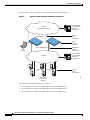
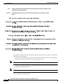
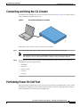
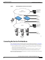
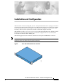
Installation and Configuration
This document is written assuming that you have already determined the 802.11 topology as described
in the Appliance Mode sections in the Product Guide. Because the Radio Resource Management (RRM)
feature automatically detects and configures the access points as they appear on the network, it is not
necessary to have any access points on the network to install and configure controllers.
The controller is a slim 9 x 5.5 x 1.5 in. (22.9 x 14.0 x 3.8 cm) chassis that can be rack, desktop, or shelf
mounted. As shown in the following figures, the controller is shipped with 19 in. (48.26 cm) EIA
rack-mount ears and four rubber mounting feet.
The following figure shows the controller, which has two front-panel 1000BASE-SX connectors.
Note
The 1000BASE-SX Network Adapters provides 100/1000 Mbps wired connections to a network through
850nM (SX) fiber-optic links using LC physical connectors.
Cisco 4100 Series Wireless LAN Controller
142196
Figure 1
Cisco 4100 Series Wireless LAN Controllers - Installation and Configuration Guide
78-17155-01
1
Installation and Configuration
Figure 2 shows a typical controller network topology and network connections:
Figure 2
Typical Controller Topology and Network Connections
Optional
management network
10/100BASE-T
Cisco Wireless
control System,
Web User
Interface, CLI
Service
port
connections
Serial
console
connection
Two 1000BASE-SX
CLI
console
Network
Distribution
system
connections
Cisco wireless
control system,
Web User
Interface, CLI
Cisco 1000
access points
network
142200
Access
point
connections
The controller communicates indirectly with up to:
•
12 associated Cisco 1000 Series lightweight access points (Model 4112).
•
24 associated Cisco 1000 Series lightweight access points (Model 4124).
•
36 associated Cisco 1000 Series lightweight access points (Model 4136).
Cisco 4100 Series Wireless LAN Controllers - Installation and Configuration Guide
2
78-17155-01
Installation and Configuration
Collecting Required Tools and Information
Figure 3 shows a typical controller deployment.
Figure 3
Typical Controller Deployment
Cisco Wireless
LAN Controller
Network
142197
Cisco 1000
Access Points
Collecting Required Tools and Information
This section lists the tools and the information that you need to have before installing the controller.
Cisco 4100 Series Wireless LAN Controller Hardware
•
Controller (ships with factory-supplied power cord and mounting hardware).
•
Network, Management network, and access point cables, as required.
•
VT-100 terminal emulator on CLI console laptop or palmtop.
•
Null modem serial cable to connect CLI console and the controller DB-9 console port.
CLI Console
Local TFTP Server
This is required for downloading error-free software updates. (Contact Cisco Technical Assistance
Center (TAC) for software updates.)
Cisco 4100 Series Wireless LAN Controllers - Installation and Configuration Guide
78-17155-01
3
Installation and Configuration
Collecting Required Tools and Information
Note
The Cisco WCS uses an integral TFTP server. This means that third-party TFTP servers cannot run on
the same workstation as the Cisco WCS, because the Cisco WCS and the third-party TFTP servers use
the same communication port.
Initial System Configuration Information
Obtain the following initial configuration parameters from the wireless LAN/network planner:
Note
•
System (Controller) name.
•
Administrative user name and password. (Default Administrative user name and password are admin
and admin, respectively.)
The Service-port interface and management interface MUST be on different subnets.
•
Service-Port Interface IP address configuration protocol (none or DHCP). (Refer Figure 2 for the
service port location.)
•
If service port configuration protocol = none, Service Port (front-panel Service port) IP Address and
Service Port netmask.
•
Management interface (DS Port, or Network Interface Port) IP address. (Refer to Figure 2 for the
distribution system port locations.)
•
Management Interface netmask.
•
Management Interface default router IP address.
•
VLAN identifier, if the Management Interface is assigned to a VLAN, or ‘0’ for an untagged VLAN.
•
Distribution System Physical Port number: 1 for either front panel GigE port
•
IP address of the default DHCP server that will supply IP addresses to clients, the controller
management interface, and optionally to the service port interface.
•
LWAPP Transport Mode, LAYER2 or LAYER3 (refer to Layer 2 and Layer 3 Operation in the
Product Guide).
•
Virtual Gateway IP Address: one fictitious, unassigned IP address (such as 1.1.1.1) to be used by all
Cisco WLAN Solution layer 3 security and mobility managers.
•
Controller Mobility Group (RF Group) name, if required.
•
802.11 Network Name (SSID) for WLAN 1. This is the default SSID that the Cisco 1000 Series
lightweight access points broadcast when they associate with the controller.
•
Whether or not to allow Static IP Addresses for clients.
* Yes = more convenient, but lower security (session can be hijacked), clients can supply their own
IP Address, better for devices that cannot use DHCP.
* No = less convenient, higher security, clients must use DHCP for an IP Address, works well for
Windows XP devices.
•
When you are configuring a RADIUS server, the server IP address, communication port, and Secret.
•
Country Code for this installation. Refer to Configuring the Cisco Wireless LAN Controller and
Cisco WLAN Solution Supported Country Codes in the Product Guide.
•
802.11b network enabled or disabled?
Cisco 4100 Series Wireless LAN Controllers - Installation and Configuration Guide
4
78-17155-01
Installation and Configuration
Determining a Physical Location
•
802.11a network enabled or disabled?
•
802.11g network enabled or disabled?
•
Radio Resource Management (RRM) (Auto-RF) enabled or disabled?
Determining a Physical Location
The controller can be installed almost anywhere, but it is more secure and reliable if installed in a secure
equipment room or wiring closet.
For maximum reliability, mount the controller using the following constraints:
•
Be sure you can reach the controller and all cables.
•
Be sure that water or excessive moisture cannot get into the controller.
•
Ensure that airflow through the controller is not obstructed. Leave at least 4 inches clear on both
sides of the controller chassis.
•
Verify that the ambient temperature remains between 0 to 40˚ C (32 to 104˚ F).
•
Be sure that the controller is within one of the following distances of equipment connected to the
optional 1000BASE-SX port:
– 220 m (722 ft.) when using 160 MHz-km rated 62.5/125 m multimode fiber.
– 275 m (902 ft.) when using 200 MHz-km rated 62.5/125 m multimode fiber.
– 400 m (1312 ft.) when using 400 MHz-km rated 50/125 m multimode fiber.
– 500 m (1641 ft.) when using 500 MHz-km rated 50/125 m multimode fiber.
Note
Each 1000BASE-SX connector provide 100/1000 Mbps wired connections to a network through
850nM (SX) fiber-optic links using LC physical connectors.
Warning Class 1 laser product. Statement 1008
Waarschuwing
Varoitus
Klasse-1 laser produkt.
Luokan 1 lasertuote.
Attention
Produit laser de classe 1.
Warnung
Laserprodukt der Klasse 1.
Avvertenza
Prodotto laser di Classe 1.
Advarsel
Laserprodukt av klasse 1.
Aviso
Produto laser de classe 1.
¡Advertencia!
Producto láser Clase I.
Cisco 4100 Series Wireless LAN Controllers - Installation and Configuration Guide
78-17155-01
5
Installation and Configuration
Determining a Physical Location
Varning!
Aviso
Advarsel
Laserprodukt av klass 1.
Produto a laser de classe 1.
Klasse 1 laserprodukt.
•
Ensure that the power cord can reach a 110 or 220 VAC grounded electrical outlet.
Cisco 4100 Series Wireless LAN Controllers - Installation and Configuration Guide
6
78-17155-01
Installation and Configuration
Installing the Chassis
Installing the Chassis
This section describes how to install the controller chassis.
Warning Only trained and qualified personnel should be allowed to install, replace, or service
this equipment. Statement 1030
Waarschuwing
Varoitus
Deze apparatuur mag alleen worden geïnstalleerd, vervangen of hersteld door bevoegd
geschoold personeel.
Tämän laitteen saa asentaa, vaihtaa tai huoltaa ainoastaan koulutettu ja laitteen
tunteva henkilökunta.
Attention
Il est vivement recommandé de confier l'installation, le remplacement et la maintenance
de ces équipements à des personnels qualifiés et expérimentés.
Warnung
Das Installieren, Ersetzen oder Bedienen dieser Ausrüstung sollte nur geschultem,
qualifiziertem Personal gestattet werden.
Avvertenza
Questo apparato può essere installato, sostituito o mantenuto unicamente da un
personale competente.
Advarsel
Bare opplært og kvalifisert personell skal foreta installasjoner, utskiftninger eller service
på dette utstyret.
Aviso
Apenas pessoal treinado e qualificado deve ser autorizado a instalar, substituir ou fazer
a revisão deste equipamento.
¡Advertencia!
Varning!
Solamente el personal calificado debe instalar, reemplazar o utilizar este equipo.
Endast utbildad och kvalificerad personal bör få tillåtelse att installera, byta ut eller
reparera denna utrustning.
Cisco 4100 Series Wireless LAN Controllers - Installation and Configuration Guide
78-17155-01
7
Installation and Configuration
Installing the Chassis
Aviso
Advarsel
Somente uma equipe treinada e qualificada tem permissão para instalar, substituir ou dar
manutenção a este equipamento.
Kun uddannede personer må installere, udskifte komponenter i eller servicere dette
udstyr.
The controller is shipped with rack-mounting ears attached, and rubber feet to mount in a separate bag.
Install the controller as follows:
•
Note
You can remove the rack mounting ears from the controller, if desired.
•
Note
When you are mounting the controller on a desktop or shelf, adhere the rubber feet to the bottom of
the chassis, and place the chassis on any secure horizontal surface.
When you are mounting the controller in an EIA-standard rack, attach the ears to the equipment rack
using the factory-supplied screws.
You can remove the rubber feet from the bottom of the controller, if desired.
You have installed the controller chassis.
Cisco 4100 Series Wireless LAN Controllers - Installation and Configuration Guide
8
78-17155-01
Installation and Configuration
Connecting and Using the CLI Console
Connecting and Using the CLI Console
For initial system configuration, use the CLI console. As shown in Figure 4, the CLI console connects
to the controller front-panel console port.
CLI Console Connection to a controller
142201
Figure 4
Follow these steps to connect the CLI console to the controller:
Step 1
Use a null-modem serial cable to connect the CLI console to the controller console port.
Note
Step 2
The controller end of the cable is female DB-9. The other end should be any kind of connector
that plugs into your VT-100 terminal emulator (usually a laptop or palmtop computer).
Be sure that the VT-100 terminal emulator (HyperTerminal, ProComm, minicom, tip, or other) is
configured for the following parameters:
•
9600 baud
•
8 data bits
•
no flow control
•
1 stop bit
•
no parity
Performing Power On Self Test
When you plug the controller into an AC power source, the bootup script initializes the system, verifies
the hardware configuration, loads its microcode into memory, verifies its Operating System software
load, and initializes itself with its stored configurations.
Cisco 4100 Series Wireless LAN Controllers - Installation and Configuration Guide
78-17155-01
9
Installation and Configuration
Performing Power On Self Test
Perform these steps to complete POST and Operating System software initialization:
Note
Step 1
This procedure is written assuming that you have connected the CLI console to the controller as
described in “Connecting and Using the CLI Console.”
Plug an AC power cord into the rear of the controller, and connect the other end to a grounded 100 to
240 VAC 50/60 Hz electrical outlet.
Note
Cisco supplies country specific standard power cord if you order it with the controller; be sure the
controller end of the cord conforms with the IEC 320 standard.
Note
If you wish to run a previous version of the controller code, press the <ESC> key immediately after the
Model and S/N line. This will take you to the Bootloader Boot Options Menu.
Step 2
Monitor the controller bootup using the CLI screen:
The Bootup script displays Operating System software initialization (code download and POST
verification) and basic configuration as shown in the following sample bootup display:
.o88b. d888888b .d8888. .o88b. .d88b.
d8P Y8
`88'
88' YP d8P Y8 .8P Y8.
8P
88
`8bo.
8P
88
88
8b
88
`Y8b. 8b
88
88
Y8b d8
.88.
db
8D Y8b d8 `8b d8'
`Y88P' Y888888P `8888Y' `Y88P' `Y88P'
Model
S/N: 01012403-10037905-01007
Press <ESC> now for additional boot options...
(If desired, press <ESC> now to display the Bootloader Boot Options Menu.)
Boot Options
Please choose an option from below:
1. Run active image (version 3.0.80.0)
2. Run backup image (version 3.0.57.0)
3. Manually perform system upgrade
4. Clear Configuration
Please enter your choice:
(Enter 1 to run the current Code, enter 2 to run the previous Code, enter 4 to run the current Code and
clear the controller configuration to factory defaults. Do not enter 3 unless directed to do so by Cisco
Technical Assistance Center (TAC).)
BOOT Uncompressing RTOS Image ... OK
Loading Code at f0100000 ...
Relocating Code to 0785e000, end 07fa649e ... OK
Detecting hardware . . . .
(This may take a long time. Do not reboot the controller at this time.)
(The rest of this process takes two to three minutes. Do not reboot the controller until you receive the
user login prompt.)
Software Copyright 2004 <company name> All rights reserved.
Cisco 4100 Series Wireless LAN Controllers - Installation and Configuration Guide
10
78-17155-01
Installation and Configuration
Using the Startup Wizard
OS Version 3.0.80.0
Checking for new bootloader: Upgrading... ok
Initializing OS Services: ok
Initializing Serial Services: ok
Initializing Network Services: ok
Starting ARP Services: ok
Starting System Services: ok
Starting Fast Path Hardware Acceleration: ok
Starting Switching Services: ok
Starting QOS Services: ok
Starting Network Interfaces: ok
Starting Access Control List Services: ok
Starting System Interfaces: ok
Starting LWAPP: ok
Starting Crypto Accelerator: ok
Starting Certificate Database: ok
Starting VPN Services: ok
Starting Security Services: ok
Starting Policy Manager: ok
Starting Virtual AP Services: ok
Starting Director: ok
Starting Mobility Management: ok
Starting Authentication Engine: ok
Starting Broadcast Services: ok
Starting Power Over Ethernet Services: ok
Starting Logging Services: ok
Starting Management Services:
Web Server: ok
CLI: ok
Secure Web: Web Authentication Certificate not found (error).
(Cisco WLAN Solution Controller)
Step 3
If this is the first time the controller has been powered up, or if you enter ‘Recover-Config’ in the User:
prompt, the bootup script runs the Startup Wizard, which prompts you for basic configuration input.
If this is the atleast the second time you have powered up the controller, the bootup script prompts you
for a login and password. Enter the login and password as described in “Logging In,” or enter
Recover-Config to reset the controller configuration to factory defaults.
In either of the two cases explained above, the controller has passed the POST test.
Using the Startup Wizard
The first time you power up the controller with a new factory-default Operating System configuration,
use the Startup Wizard to do the following:
Note
Note
Use the information you collected in “Collecting Required Tools and Information” for this step.
1.
Enter the system (controller) name, up to 32 printable ASCII characters.
2.
Enter the Administrative user name and password, each up to 24 printable ASCII characters. The
default Administrative user name and password are admin and admin, respectively.
The Service-Port and Management Interfaces must be on different subnets
Cisco 4100 Series Wireless LAN Controllers - Installation and Configuration Guide
78-17155-01
11
Installation and Configuration
Logging In
Logging In
To log into the controller, perform these steps:
Step 1
Enter a valid login and password to enter the CLI.
User:
Password:
Note
Step 2
The login and password functions are case sensitive. The default administrative user login and password
are admin and admin, respectively.
The CLI displays the root-level system prompt:
(system prompt)>
The system prompt can be any alphanumeric string up to 31 characters. You can change it by entering
the following command:
(system prompt)>config prompt
Because this is a user-defined variable, it is omitted from the rest of this documentation.
Step 3
The CLI automatically logs you out without saving any changes after five minutes of inactivity. This
automatic logout can be set from 0 (never log out) to 160 minutes entering the following command:
(system prompt)>config serial timeout
Refer to the Navigating the CLI and Logging Out of the CLI sections in the Product Guide for more
information.
Connecting the Network (Distribution System)
See the following figure for connections from the network (Distribution System) to the controller. The
connections are:
•
Note
Two 1000BASE-SX (GigE, front panel, LC physical port, multi-mode fiber-optic cable).
The 1000BASE-SX connectors provide 100/1000 Mbps wired connections to a network through 850nM
(SX) fiber-optic links using LC physical connectors.
Depending on the distribution system physical port to be assigned as explained in Cisco Wireless LAN
Controller Interfaces section in the Product Guide, use CAT-5, CAT-5e, CAT-6, or CAT-7 ethernet cables
or LC compatible fiber-optic cable to connect the network equipment to the controller.
Cisco 4100 Series Wireless LAN Controllers - Installation and Configuration Guide
12
78-17155-01
Installation and Configuration
Connecting the Service Port Interfaces
Figure 5
External Equipment Connections to the Controller
Optional
management network
10/100BASE-T
Cisco Wireless
control System,
Web User
Interface, CLI
Service
port
connections
Serial
console
connection
Two 1000BASE-SX
CLI
console
Network
Distribution
system
connections
Cisco wireless
control system,
Web User
Interface, CLI
142200
Access
point
connections
Cisco 1000
access points
network
Connecting the Service Port Interfaces
After connecting the network (Distribution System) to the controller as described in “Connecting the
Network (Distribution System),” you can make Cisco Wireless Control System, Web User Interface, or
CLI console (management interface) connections to the controller in any one of the following ways.
•
You can connect any of the Cisco Wireless Control System, Web User Interface, or CLI console
directly to the secure front-panel Service Port.
•
You can connect any or all of the Cisco Wireless Control System, Web User Interface, or CLI
console through a dedicated management network directly to the front-panel Service port.
Refer to the following figures when connecting the Cisco Wireless Control System, Web User Interface,
and/or CLI console to the controller.
Cisco 4100 Series Wireless LAN Controllers - Installation and Configuration Guide
78-17155-01
13
Installation and Configuration
Connecting the Service Port Interfaces
•
For a front-panel Cisco Wireless Control System, Web User Interface, or CLI console connection,
use CAT-5, CAT-5e, CAT-6, or CAT-7 ethernet cables to connect the Cisco Wireless Control System
(Cisco WCS) Server, Web User Interface, or another CLI console to the dedicated front-panel
Service port.
CLI Console Connection to a Controller through a Null-Modem Serial Cable
142199
Figure 6
•
For a front-panel Cisco Wireless Control System, Web User Interface, or CLI console connection,
use CAT-5, CAT-5e, CAT-6, or CAT-7 ethernet cables to connect the management network to the
front-panel service port.
Use the appropriate cables to connect the Cisco Wireless Control System, Web User Interface, or
CLI console to the optional management network.
CLI Console Connection to Controller through a Management Network
Optional management
network
142198
Figure 7
Cisco 4100 Series Wireless LAN Controllers - Installation and Configuration Guide
14
78-17155-01
Installation and Configuration
Connecting Access Points
Connecting Access Points
After you have installed and configured the controller, use CAT-5, CAT-5e, CAT-6, or CAT-7 ethernet
cables to connect the access points to the network (Distribution System) as shown in the following
figure.
Note
As soon as the controller is activated, it starts to scan for access points on all connected ports. When it
detects an access point, it records its MAC address in its database. The Radio Resource Management
(RRM) function then automatically configures the access point to start transmitting and start allowing
clients to connect through the access points.
Figure 8
Access Points Connected to a Controller
Cisco Wireless
LAN Controller
Network
142197
Cisco 1000
Access Points
Where to Go from Here
You have completely installed the controller hardware.
•
Register your controller.
•
Refer to the Configuring the Cisco Wireless LAN Controllers in the Product Guide for more
information on configuring the controller.
•
Refer to the Product Guide for more information on configuring, operating, maintaining and
troubleshooting the controller.
Cisco 4100 Series Wireless LAN Controllers - Installation and Configuration Guide
78-17155-01
15
Installation and Configuration
Where to Go from Here
Cisco 4100 Series Wireless LAN Controllers - Installation and Configuration Guide
16
78-17155-01