1
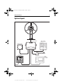
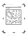
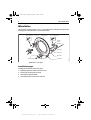
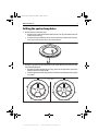
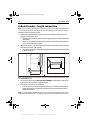
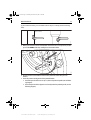
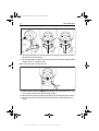
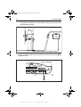
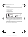
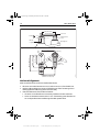
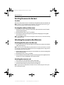
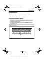
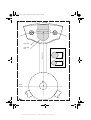
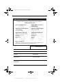
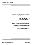
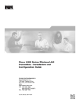
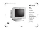
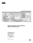
87063_1.book Page 1 Monday, December 19, 2005 3:22 PM
MK II Wheel
Drive
Installation Guide
Document number: 87063-1
Date: December 2005
www.Busse-Yachtshop.de
email: [email protected]
87063_1.book Page 2 Monday, December 19, 2005 3:22 PM
www.Busse-Yachtshop.de
email: [email protected]
87063_1.book Page 3 Monday, December 19, 2005 3:22 PM
MK II Wheel Drive
3
System layout
Wheel drive
Course computer
Boat's electrical
distribution panel
Fluxgate compass
Rudder position sensor
Control unit
D8908-1
NMEA
instrument
or navigator
www.Busse-Yachtshop.de
email: [email protected]
87063_1.book Page 4 Monday, December 19, 2005 3:22 PM
4
MK II Wheel Drive
Parts supplied
Wheel drive parts
Pedestal bracket
16 mm spoke
clamp insert (x3)
12 mm spoke
clamp insert (x3)
Clamp screw,
M5 x 16 mm (x6)
Bracket screw,
No 10 x 3/4 in (x4)
Wheel drive
Spoke clamp (x3)
6 mm
drill bit
4 mm
drill bit
3 mm
allen key
Power cable
4.5 m (15 ft)
Ball joint (x2)
Tiller pin
No 8 x ¾ inch
Pan head screw (x3)
Cable clip
and screw,
No 6 x 1/2 in
Rudder position sensor
Stud
Nut (x2)
Optional: Bulkhead/box pedestal fitting kit E15017 (if required)
www.Busse-Yachtshop.de
email: [email protected]
D8885-1
No 8 x ¾ inch
Countersunk head screw (x2)
87063_1.book Page 5 Monday, December 19, 2005 3:22 PM
MK II Wheel Drive
5
Tools required
1. Tape measure (metric/imperial)
2. Pliers and cross-head/pozi-drive screwdriver
3. Hammer and center punch
4. Pencil, masking tape
5. Spanner (Wrench) for the wheel nut
6. Washing-up liquid (to lubricate the spokes)
7. Hacksaw to cut the pedestal bracket
8. Power/battery Drill
9. 4 mm + 6 mm drill bits (supplied)
10. 3 mm allen key (Hex key, supplied)
www.Busse-Yachtshop.de
email: [email protected]
87063_1.book Page 6 Monday, December 19, 2005 3:22 PM
6
MK II Wheel Drive
Wheel drive
The Raymarine wheel drive will fit 3, 4, 5, 6, 7 or 8 spoke wheels. It is designed to operate with
steering systems with between 1 to 3.5 turns lock to lock.
Clamp screw,
M5 x 16 mm (x6)
Wheel drive
front cover
Pre-drilled spoke
clamp holes (x2)
Bracket screw,
No 10 x 3/4 inch (x4)
Pedestal
bracket
Bracket pin
Cable plug
Cable socket
Spoke clamp (x3)
Clamp insert (x3)
Wheel drive – main parts
Installation stages
Installing the wheel drive involves four steps:
1.
2.
3.
4.
Drilling the spoke clamp holes in the front cover.
Securing the wheel drive to the wheel.
Attaching the pedestal bracket.
Connecting the drive to the course computer.
www.Busse-Yachtshop.de
email: [email protected]
Clutch lever
D8886-1
Motor tube
87063_1.book Page 7 Monday, December 19, 2005 3:22 PM
MK II Wheel Drive
7
Drilling the spoke clamp holes
D8888-1
1. Remove the wheel drive front cover:
• the front cover is held onto the wheel drive by three ‘push-fit’ posts which sit in three
sockets on the drive ring
• to remove the cover, hold the motor in one hand and use your other hand to pull the
cover up and away from the drive unit (as shown below)
2. Identify the appropriate spoke clamp holes for your wheel. With the arrow at the top, refer
to the following diagrams:
• the holes are numbered inside the cover (e.g. if you have a 5 spoke wheel, you need to
drill the 4 locations marked with ‘5’)
• mark the appropriate spoke clamp holes and check them by holding the cover against
your wheel
Top 2 spoke clamp holes
are pre-drilled
7 spokes
D8889-1
5 spokes
www.Busse-Yachtshop.de
email: [email protected]
87063_1.book Page 8 Monday, December 19, 2005 3:22 PM
8
MK II Wheel Drive
Top 2 spoke clamp holes
are pre-drilled
4 or 8 spokes
D8892-1
3 or 6 spokes
Note: The wheel drive is designed to work with 3 spoke clamps on 4 or 8 spoke wheels. For cosmetic
reasons, however, you may want to fit an extra spoke clamp to the fourth spoke. Raymarine dealers can
supply an extra spoke clamp (part number A18089).
3. Drill the appropriate spoke clamp holes using the larger of the supplied drill bits (6.0 mm
or 1/4 in):
• drill from the inside, placing a piece of scrap wood under the cover to produce a clean
exit hole
• you will need to drill 4 new holes so the cover has 6 holes in total (2 for each spoke
clamp)
Note: The spoke clamps will cover these exit holes, so they will not be visible when the wheel drive is
installed.
D8894-1
Piece of scrap wood
www.Busse-Yachtshop.de
email: [email protected]
87063_1.book Page 9 Monday, December 19, 2005 3:22 PM
MK II Wheel Drive
9
4. Align the cover with the wheel drive:
• the two pre-drilled holes (marked with an arrow) must line up with their matching pair
of threaded inserts on the drive ring (also marked with an arrow)
• make sure that the other spoke clamp holes align with their threaded inserts
Note: The cover will only fit back onto the wheel drive when you have aligned the two parts correctly.
Pre-drilled holes
(marked with arrow)
Pair of threaded inserts
(marked with arrow)
D8896-1
Drive ring
Front cover
Drive unit
5. Fit the cover back onto the wheel drive:
• press the cover in the three places shown on the diagram below to push each of the
posts back into its locating socket
Note: This step is easier with the clutch engaged.
D8897-1
TOP
www.Busse-Yachtshop.de
email: [email protected]
87063_1.book Page 10 Monday, December 19, 2005 3:22 PM
10
MK II Wheel Drive
Securing the wheel drive to the wheel
1. Remove the wheel from the pedestal and place it on top of the drive unit, with the front of
the wheel and drive both facing up.
2. Using the wheel drive template at the end of this booklet, select the correct set of spoke
clamp inserts for your wheel:
• measure the spoke diameter at a distance of about 135 mm (5.3 in) from the center of
the wheel
• select the appropriate set of inserts: the wheel drive is supplied with 2 sets of 3 inserts
suitable for 12 mm (1/2 in) and 16 mm (5/8 in) diameter spokes – each insert is marked
with its size
3. Fit the first spoke clamp:
• lubricate the spoke with washing-up liquid – so you can slide the spoke clamp along
the spoke to adjust its position
• place the insert on the spoke about 135 mm (5.3 in) from the wheel center – this distance is not critical as the wheel drive will self-center as you fit all 3 spoke clamps
• place the spoke clamp onto the insert, making sure that you have correctly located the
clamp insert in the clamp
• locate 2 of the clamp screws (M5 x 16 mm allen-head screws)
• lightly tighten the screws using the 3 mm allen key (Hex key, supplied)
5.3
in)
D8898-1
135
(
mm
4. Repeat step 3 to fit the other 2 spoke clamps. As you fit each one, adjust the position of the
wheel relative to the wheel drive so the holes in the clamp line up with the holes in the
cover. As you do this, the wheel drive will self-center on the wheel.
5. After fitting all 3 spoke clamps, fully tighten the screws.
www.Busse-Yachtshop.de
email: [email protected]
87063_1.book Page 11 Monday, December 19, 2005 3:22 PM
MK II Wheel Drive
11
Attaching the pedestal bracket
Note: If your wheel is bulkhead or box pedestal mounted, you will need to obtain a bulkhead fitting kit
(part number E15017) from your Raymarine dealer. Fitting instructions are supplied with the kit.
Motor tube location
Depending on the design of your pedestal and any surrounding obstructions, you can mount
the wheel drive in one of two ways:
• Slot 1 installation: the standard position uses slot 1 on the back of the wheel drive
(the slot closest to the motor tube) so the motor tube is at the bottom to the right of
the pedestal
• Slot 2 installation: the alternative installation uses slot 2 to position the motor
tube at the top to the left of the pedestal
Select the appropriate slot so the motor tube is clear of obstructions.
CAUTION: If you use slot 2 and you have a pedestal-mounted compass, the
drive motor may affect compass readings.
Slot 1 installation:
motor tube at
bottom right
Slot 2 installation:
motor tube at
top left
Slot 1
D8899-1
Slot 2
www.Busse-Yachtshop.de
email: [email protected]
87063_1.book Page 12 Monday, December 19, 2005 3:22 PM
12
MK II Wheel Drive
Pedestal bracket – length and position
Note: If you are replacing an existing 4000 wheel drive, you need to: remove the old pedestal bracket,
cut the new bracket pin to the correct length (see steps 2 and 3 below), then secure it in the standard
orientation using the existing pedestal holes.
1. Fit the wheel onto the pedestal, tighten the wheel nut to hold the wheel in place, and
engage the wheel drive’s clutch:
• if possible, lock the wheel in position with the appropriate slot centered at the bottom
of the wheel
• otherwise, you will find it useful to have an assistant to hold the wheel in position so
you can locate the bracket correctly
2. Measure dimension A – the distance between the front of the pedestal and the rear edge
of the drive’s front cover (see diagram):
• you may find it easiest to hold the bracket below the wheel drive and mark dimension
A directly on the pin
Cut here
10 mm
D8900-1
A
A
Note: If the wheel is bent or not running true, dimension A will change with the wheel position. Mea-
sure the smallest distance.
3. Use a hacksaw to cut the pin 10 mm (0.4 in) LONGER than dimension A. Remove any
sharp edges at the cut end with sandpaper or a file.
4. Place the pin end in slot 1 or 2 (as required):
• to do this you may need to loosen the wheel nut so you can slide the wheel forward
slightly, place the pin end in the slot, return the wheel to its normal position and retighten the wheel nut
Note: You can install the pedestal bracket either way up. In the standard orientation the pin is at the
bottom (below the mounting holes – see diagram). If obstructions on the pedestal prevent you from us-
www.Busse-Yachtshop.de
email: [email protected]
87063_1.book Page 13 Monday, December 19, 2005 3:22 PM
MK II Wheel Drive
13
ing the standard orientation, you can install the bracket so the pin is at the top (above the mounting
holes).
Alternative
D8901-1
Standard
(also for retro-fit)
D8902-1
5. Making sure the slot is central at the bottom of the drive unit (6 o’clock position) and the
pin is in the middle of the slot, carefully draw around the bracket.
6. Remove the wheel, then hold the bracket on the pedestal in the location you have
marked.
7. Check the position and alignment of the pedestal bracket:
• the bracket pin should be 154 mm (6.1 in) below the pedestal spindle (see the following diagram)
• the bracket pin should be aligned so it is directly below the pedestal spindle (see the
following diagram)
www.Busse-Yachtshop.de
email: [email protected]
87063_1.book Page 14 Monday, December 19, 2005 3:22 PM
14
MK II Wheel Drive
D8903-1
154 mm
(6.1 in)
8. When the pedestal bracket is correctly positioned and aligned, mark around the inside of
the slots, then remove the bracket.
9. Use a center-punch to mark the center of each slot, then use the smaller supplied drill bit
to drill a 4.0 mm (5/32 in) diameter hole.
D8904-1
Note: Drill at right angles to the pedestal surface.
10. Hold the bracket in place then lightly tighten the four cross-head screws (No 10 x 3/4 in).
As you do this, make sure the bracket is correctly aligned.
11. Replace the wheel, making sure that you locate the pin in the correct slot (slot 1 or slot 2).
12. Turn the wheel with the clutch off to check that the bracket is correctly positioned and
aligned.
www.Busse-Yachtshop.de
email: [email protected]
87063_1.book Page 15 Monday, December 19, 2005 3:22 PM
MK II Wheel Drive
15
Note: If the wheel is bent or the wheel drive is off center, the pin will move up and down in the back
plate slot. As long as the pin does not hit the top or bottom of the slot, this pin movement will not affect
the drive unit’s performance.
13. When you have checked alignment, fully tighten all four screws.
Connecting to the course computer
When you have attached the pedestal bracket, you need to connect the wheel drive to the
course computer. The drive unit is supplied with 4.5 m (15 ft) of 2-core cable with a
waterproof socket at one end.
1. Connect the socket to the plug on the wheel drive’s motor tube:
• remove the socket cover
• pull back the plug cover
• align the locking ring, plug and socket as shown below
Socket
Contact
Motor tube
Plug
Plug cover
(pulled back)
Cable
Socket cover
D8905-1
Locking ring
• push the plug firmly into the socket
• turn the locking ring 90° clockwise
• make the connection waterproof by pulling the plug cover across so it protects the
plug and socket
Note: To remove the plug, pull back the cover and turn the locking ring 90° anti-clockwise. If you dis-
connect the socket for any reason, always use the attached rubber cover to protect the socket.
2. Route the cable through the pedestal (or guard rail) and back to the course computer:
www.Busse-Yachtshop.de
email: [email protected]
87063_1.book Page 16 Monday, December 19, 2005 3:22 PM
16
MK II Wheel Drive
D8906-1
• if the pedestal has a cable duct, use this for the drive cable to make sure that it cannot
foul the steering mechanism
3. Run the drive cable back to the course computer and connect the two cores to the Drive
terminals as shown.
Course computer
SEATALK
POWER IN
RF GND
Blue
D8907-1
Brown
www.Busse-Yachtshop.de
email: [email protected]
87063_1.book Page 17 Monday, December 19, 2005 3:22 PM
MK II Wheel Drive
17
Rudder position sensor
The rudder position sensor connects directly to the boat’s tiller arm or quadrant.
Installing the sensor involves five steps:
1.
2.
3.
4.
5.
Ensuring correct alignment
Securing the sensor to the boat
Attaching the sensor to the tiller arm
Checking alignment
Connecting to the course computer
70 mm (2.75 in)
D8916-1
140 mm (5.5 in)
60 mm (2.4 in)
187 mm (7.35 in)
Ensuring correct alignment
CAUTION: Take care to ensure correct rudder sensor alignment. If the sensor
is not correctly aligned, the autopilot system will not perform accurately.
Vertical alignment
When viewed from the front (as shown in the illustration below), the connecting rod should
be as level as possible, so the ball-joints at each end are level. It should also remain parallel to
the tiller arm’s plane of rotation at all times.
Note: If misalignment exceeds +/-5° the ball-joints will bind or fail.
www.Busse-Yachtshop.de
email: [email protected]
87063_1.book Page 18 Monday, December 19, 2005 3:22 PM
18
MK II Wheel Drive
Front view - rudder amidships
Ball joints (level)
Connecting rod
Sensor arm
Parallel
Rudder position
sensor
Tiller arm
or quadrant
Mounting base
Top view - rudder amidships
Cable entry
Parallel
60˚
90˚
60˚
Maximum
permitted
travel: +/- 60˚
Minimum: 75 mm (3 in)
Maximum: 310 mm (12 in)
D8917-1
Min: 101 mm (4 in)
Optimum: 140 mm (5.5 in)
Max: 190 mm (7.5 in)
Aft
Horizontal alignment
When viewed from above (as shown in the illustration above):
• the sensor arm must be between 75 mm (3 in) and 310 mm (12 in) from the tiller arm
• with the rudder amidships, the sensor arm should be at 90° to the connecting rod and
directly opposite the cable entry point on the sensor body
• when the rudder moves from hardover to hardover:
• the sensor arm and the tiller arm must remain parallel to each other at all times
• sensor arm movement must not exceed +/- 60°: if the steering system drives the sensor arm beyond these limits it will damage the rudder position sensor
www.Busse-Yachtshop.de
email: [email protected]
87063_1.book Page 19 Monday, December 19, 2005 3:22 PM
MK II Wheel Drive
19
Securing the sensor to the boat
Location
Mount the rudder position sensor on a suitable base alongside the rudder stock and tiller arm.
Note: If necessary, you can install the sensor upside down. If you mount the sensor in this way, you
must swap the red and green cable connections at the course computer.
Securing the rudder position sensor
1. Hold the sensor in place, mark the mounting holes, then remove the sensor (if required,
use the template supplied).
2. Drill the pilot holes using a 3 mm (1/8 in) drill bit.
3. Attach the sensor to the mounting base using the three self-tapping screws supplied
(pan-head No 8 x 3/4 inch).
Note: To make minor adjustments to the sensor alignment, loosen the screws, rotate the sensor body,
then re-tighten the screws.
Attaching the sensor to the tiller arm
Attaching the tiller pin to the tiller arm
1. For optimum performance, mount the tiller pin on the tiller arm 140 mm (5.5 in) from the
rudder stock center line.
Note: If necessary, you can fit the tiller pin anywhere between 101 mm (4 in) and 190 mm (7.5 in) from
the rudder stock. This will not affect autopilot performance, but will slightly alter the scaling of the rudder angle display shown on the control unit.
2. Hold the tiller pin in place (either along or across the tiller arm), mark the mounting holes
then remove the tiller pin.
3. Drill pilot holes using a 3 mm (1/8 in) drill bit.
4. Attach the tiller pin to the tiller arm using the two self-tapping screws supplied (countersunk No 8 x 3/4 inch) or suitable bolts, nuts and lock washers.
Attaching the connector rod
1. Use a hacksaw to cut the threaded connector rod to length.
2. Screw the lock nuts onto the road and then the ball-pin sockets.
3. Press the sockets onto the pins on the sensor arm and tiller pin.
Note: To give the precise rudder position, the rudder sensor has a built-in spring to remove any free
play in the linkage to the tiller.
www.Busse-Yachtshop.de
email: [email protected]
87063_1.book Page 20 Monday, December 19, 2005 3:22 PM
20
MK II Wheel Drive
Checking alignment
Move the rudder from hardover to hardover and check that at all rudder angles:
• all moving parts of the sensor remain free from any obstructions
• the sensor and connecting rod remain accurately aligned
• the ball joints do not bind
Connecting to the course computer
1. The rudder position sensor is supplied with 10 m (32 ft) of cable. Route the cable to the
course computer, taking into account the EMC installation guidelines detailed in the
course computer installation manual.
2. Connect the four cores of the cable (color for color) to the Rudder terminals on the
course computer as shown.
Note: If the standard cable is not long enough, your Raymarine dealer can supply a 10 m (30 ft) exten-
sion cable (part number: D173).
Course computer
Screen
Red
Red
Screen Yellow
Screen Yellow
Red
Yellow
Red
Yellow
Red
Blue
Green
Blue
Screen Screen
Green
RATE GYRO RUDDER
NMEA
SeaTalk
SeaTalk CLUTCH
D8918-1
FLUXGATE
www.Busse-Yachtshop.de
email: [email protected]
87063_1.book Page 21 Monday, December 19, 2005 3:22 PM
MK II Wheel Drive
21
Template
The wheel drive - spoke clamp template is printed on the following page.
www.Busse-Yachtshop.de
email: [email protected]
87063_1.book Page 22 Monday, December 19, 2005 3:22 PM
Wheel drive - spoke clamp template
Spoke clamp
Spoke clamp
insert
16 mm (5/8 in)
12 mm (1/2 in)
135 mm (5.3 in)
Spoke diameters
Center
of wheel
D5410-1
www.Busse-Yachtshop.de
email: [email protected]
87063_1.book Page I Monday, December 19, 2005 3:22 PM
Raymarine World Wide Warranty
I
Raymarine World Wide Warranty
Raymarine Inc.
APPLICABLE TO PRODUCTS SOLD THROUGH OFFICIAL RAYMARINE INC. DEALERS, DISTRIBUTORS AND BOAT
BUILDERS WITHIN THE AMERICAS AND CARIBBEAN.
Limited warranty
Subject to the terms, conditions and limitations set forth in this U.S. Limited Warranty (hereinafter the ‘Warranty’),
Raymarine warrants that its products, when properly installed and used, will be free from defects in material and
workmanship for a period of twenty-four (24) months (with respect to VHF radios, a period of thirty-six (36) months),
from the date of first purchase (the ‘Warranty Period’).
For the purposes of this warranty, ‘date of first purchase’ means the date that the product was purchased by the first
retail customer; or in the case of a product installed on a new vessel by a certified Raymarine original equipment
manufacturer (a ‘Raymarine OEM’), the date that such vessel was purchased by the first retail customer.
Raymarine will, at its sole option, repair or replace any defective products or components returned during the
Warranty Period in accordance with the terms, conditions and limitations set forth below. Such repairs or
replacement will be the sole remedy of the customer under this Warranty.
Obtaining Warranty Service
Standard Warranty Service
To qualify for standard warranty service the product must be returned to a Raymarine-certified service agent, or
directly to Raymarine in person, or by mail (i) within the Warranty Period, and (ii) within thirty (30) days of the alleged
product failure.Any products returned by mail must be securely packaged and sent pre-paid and insured to
Raymarine or to a Raymarine-certified service agent. All products, whether returned in person or by mail, must be
accompanied by a copy of the original sales receipt, to be eligible for standard warranty service.
A list of Raymarine-certified service agents is available from Raymarine Technical Support or at
www.raymarine.com
‘On Board’ Warranty Service
For any Raymarine product or system that (i) has been installed on your vessel by a Raymarine-certified service agent
or by a Raymarine OEM, and (ii) has a MSRP equal to or greater than USD $2,500, you are eligible to receive warranty
service by a Raymarine certified service agent on-board your vessel (‘On Board Warranty Service’) for a period of 12
months from the date of first purchase of such product or system, or the date of first purchase of the vessel on which
such product or system has been installed (the ‘On Board Warranty Period’). In order to obtain On Board Warranty
Service eligible customers MUST:
•
(i) within the On Board Warranty Period, and (ii) within thirty (30) days from the date of the alleged failure
giving rise to the warranty claim for which you are requesting On Board Warranty Service, contact a local
Raymarine-certified service agent and request On Board Warranty Service.
• Present to the Raymarine-certified service agent a copy of the original sales receipt for the product,
together with proof of the date of installation of the product by a Raymarine-certified service agent. The
service agent may at its sole option, accept or deny such proof of purchase and proof of installation as sufficient to qualify you for On Board Warranty Service.
Costs associated with travel, mileage, taxi fares, launch or docking fees, aircraft or vehicle rental, meals, customs,
shipping, communication charges, and service agent travel costs are specifically excluded from coverage under this
Warranty and are your responsibility. In addition, this Warranty does not cover fees associated with hauling,
shipping or towing your vessel to a Raymarine-certified agent.
www.Busse-Yachtshop.de
email: [email protected]
87063_1.book Page II Monday, December 19, 2005 3:22 PM
II
Upon the expiration of the On Board Warranty Period, you are still eligible to receive standard warranty service for the
remaining term of the Warranty Period, but will not be eligible for continued On Board Warranty Service.
Limitations and Exclusions
In addition to any other limitations and exclusions set forth herein, Raymarine is not responsible for, and this
Warranty does not cover:
•
•
•
•
•
•
•
failures due to abuse, misuse, accident, unauthorized alteration or repair, improper installation (whether or
not by a Raymarine-certified service agent), shipping damage or corrosion;
Costs associated with routine system checkouts, alignment/calibration, seatrials or commissioning;
repair or replacement of consumable items, including, without limitation, fuses, batteries, drive belts, radar
mixer diodes, snap-in impeller carriers, impellers, impeller bearings and impeller shafts;
costs associated with overtime or premium labor costs;
differences in material, coloring or size that may exist between actual products and the pictures or descriptions of such products in our advertising, advertising literature or on the Internet;
products purchased by a customer from a United States dealer via the Internet if such products were not
delivered and installed within the United States; or
the replacement of missing components from the package of any product purchased through an online
auction site.
Other conditions
This Warranty is fully transferable provided that you furnish the original proof of purchase to Raymarine or, in the case
of On Board Warranty Service, to a Raymarine-certified service agent. This Warranty is void if the label bearing the
serial number has been removed or defaced.
TO THE EXTENT CONSISTENT WITH STATE AND FEDERAL LAW, THE FOREGOING WARRANTY IS
RAYMARINE’S SOLE WARRANTY AND IS APPLICABLE ONLY TO NEW PRODUCTS PURCHASED IN THE
UNITED STATES OF AMERICA. THE PROVISIONS OF THIS WARRANTY ARE IN LIEU OF ANY OTHER WRITTEN
WARRANTY, WHETHER EXPRESSED OR IMPLIED, WRITTEN OR ORAL, INCLUDING ANY WARRANTY OF
MERCHANTABILITY OR FITNESS FOR A PARTICULAR PURPOSE.
THE LIABILITY OF RAYMARINE TO A CUSTOMER UNDER THIS WARRANTY, WHETHER FOR BREACH OF CONTRACT,
TORT, BREACH OF STATUTORY DUTY OR OTHERWISE SHALL IN NO EVENT EXCEED AN AMOUNT EQUAL TO TEN (10)
TIMES THE MANUFACTURER’S SUGGESTED RETAIL PRICE OF THE PRODUCT GIVING RISE TO SUCH LIABILITY AND
IN NO EVENT SHALL RAYMARINE BE LIABLE FOR SPECIAL, INCIDENTAL, CONSEQUENTIAL OR INDIRECT DAMAGES.
SOME JURISDICTIONS DO NOT ALLOW EXCLUSION OR LIMITATION OF INCIDENTAL OR CONSEQUENTIAL
DAMAGES SO THE ABOVE LIMITATIONS OR EXCLUSIONS MAY NOT APPLY TO YOU. THIS WARRANTY GIVES YOU
SPECIFIC LEGAL RIGHTS AND YOU MAY ALSO HAVE OTHER RIGHTS, WHICH VARY FROM JURISDICTION TO
JURISDICTION.
This Warranty supersedes and replaces all previous Warranties.
January 2005
www.Busse-Yachtshop.de
email: [email protected]
87063_1.book Page III Monday, December 19, 2005 3:22 PM
Raymarine World Wide Warranty
III
Raymarine UK Ltd.
APPLICABLE TO PRODUCT SOLD THROUGH OFFICIAL RAYMARINE UK LTD. DEALERS, DISTRIBUTORS AND BOAT
BUILDERS WITHIN EUROPE, THE MIDDLE AND FAR EAST, AFRICA AND AUSTRALASIA.
Limited Warranty
The Raymarine warranty terms and conditions as described below do not affect the customers legal rights and
complies with EU Directive 1999/44/EC.
In order to ensure that the product continues to operate efficiently and reliably, we recommend that, before using the
product, the customer carefully reads the Owner’s Handbook and follows the advice on the safe and correct
operation and use of the product. We recommend that the Raymarine product is installed by a Raymarine certified
installer. Installation by persons other than a Raymarine certified installer may invalidate the warranty.
1. Product warranty
1.1 Raymarine warrants each new product to be of good materials and workmanship. Raymarine, or its approved
agents, will repair or exchange under warranty any parts or product proven to be defective in material or
workmanship under normal use, for a period of 2 years (24 months) from date of sale to end user, subject to the limits
contained in this warranty document.
1.2 The Raymarine warranty covers the parts and labour associated with any warranty repair as described above,
provided that the product is returned to Raymarine or one of its approved agents.
1.3 Raymarine reserve the right to replace under warranty, not repair, certain Raymarine products subject to the
limitations below, provided that they are returned to the nearest Raymarine National Distributor. For details of such
products refer to the internet at www.raymarine.com or contact your nearest Raymarine National Distributor.
2. Onboard warranty
2.1 In addition to the Product warranty cover as described above, Raymarine will, authorize onboard warranty service
by the nearest Raymarine approved service agent, subject to the maximum mileage and other limits referred to in
paragraph 4.12 below, on products, where proof of installation, or commission by Raymarine certified installers, can
be shown.
2.2 The warranty provides for onboard repair or exchange of the product, by Raymarine or its approved service
agents, for a period of 2 years (24 months), subject to the limits contained in this warranty document. In the case of a
product installed, by a Raymarine certified OEM installer, on a new boat prior to the sale of the boat to a customer, the
2-year period will begin on the date of the sale of the boat to the customer. In the case of a product installed, by a
Raymarine certified installer, on a boat already in the possession of the customer, the 2-year period will begin on the
date of the commissioning of the installed product.
2.3 Certain Raymarine products are not covered by onboard warranty unless the products are pre-registered and on
board warranty is purchased from the Raymarine certified installer. For details of such products refer to the internet at
www.raymarine.com or contact your nearest Raymarine National Distributor.
2.4 The Purchaseable onboard warranty is subject to the limitations below.
3.Obtaining warranty service
3.1 In the event of warranty service being required, the customer should contact Raymarine Technical Support or the
nearest Raymarine approved service agent - the contact details of Raymarine Technical Support and a full list of the
names and details of worldwide service agents are available on the internet at www.raymarine.com and in the
Owner’s Handbook.
www.Busse-Yachtshop.de
email: [email protected]
87063_1.book Page IV Monday, December 19, 2005 3:22 PM
IV
3.2 In cases where the customer is requesting a warranty service and a Raymarine certified installer has not installed
the product; i.e. Product warranty, the affected product must be returned to the customer’s local Raymarine approved
service agent or direct to Raymarine with:
3.2.1 proof of purchase showing the date of purchase and the name of the supplier of the product; and
3.2.2 the serial number of the affected product; or
3.2.3 a warranty card completed by the product supplier (which will contain the information required by
paragraphs 3.2.1 and 3.2.2).
Subject to the limitations below, the product will be repaired or replaced (at the discretion of Raymarine or a
Raymarine Service Agent) at no further cost and promptly returned to the customer.
3.3 In cases where the customer is making a warranty claim and the product has been installed by a Raymarine
certified installer, (boat builder, installer, dealer etc.) i.e. Onboard warranty, the nearest Raymarine approved service
agent should be contacted and onboard service requested (which will be subject to the limits referred to in paragraph
4.12 below). Before the onboard warranty service is performed, the customer must have available:
3.3.1 proof of purchase showing the date of purchase and the name of the supplier of the product; and
3.3.2 the serial number of the affected product; or
3.3.3 proof of installation of the product by a Raymarine certified installer; or
3.3.4 a warranty card completed by the product supplier (which will contain the information required by
paragraphs 3.3.1 and 3.3.3).
3.4 In cases where onboard warranty has been purchased - as described in 2.3; the nearest Raymarine approved
service agent should be contacted and onboard service requested, information detailed in 3.3.1 and 3.3.2 is required.
Onboard warranty service will only be performed if the product serial number confirms that the onboard warranty
service has been purchased and is valid.
4. Warranty limitations
4.1 Raymarine warranty policy does not apply to any product that has been subjected to accident, abuse or misuse,
shipping damage, alterations, corrosion, incorrect and/or non-authorized service, or products on which the serial
number has been altered, mutilated or removed.
4.2 Certain products do not carry the onboard warranty, as described in section 2 above, unless the onboard warranty
cover is purchased at the time of installation. The purchaseable onboard warranty is only available on products
purchased in specific territories, for further details refer to the internet at www.raymarine.com or contact your
nearest Raymarine National Distributor.
4.3 Products purchased outside the country of installation will not be covered by onboard warranty.
4.4 Raymarine assumes no responsibility for damage incurred during installation or as a result of improper
installation.
4.5 This warranty does not cover routine system checkouts, alignment/calibration, seatrials or commissioning, unless
required by replacement of part(s) in the area being aligned.
4.6 Raymarine assumes no responsibility for damage caused by or to other equipment, systems or components
occasioned by improper or unauthorized connection, or use, of the product.
4.7 Consumable items, including, but not limited to: fuses, batteries, drive belts, radar mixer diodes, snap-in impeller
carriers, impellers, impeller bearings, and impeller shafts are specifically excluded from this warranty. A complete list
of the consumable items relating to each product can be found in the Owner’s Handbook and/or on the internet at
www.raymarine.com.
4.8 All costs associated with transducer replacement, other than the cost of the transducer itself, are specifically
excluded from this warranty.
4.9 Overtime/premium labour portion of services outside of normal working hours is not covered by this warranty.
www.Busse-Yachtshop.de
email: [email protected]
87063_1.book Page V Monday, December 19, 2005 3:22 PM
Raymarine World Wide Warranty
V
4.10 If repairs are necessary under the warranty, the affected product must be forwarded to a Raymarine facility or a
Raymarine approved service agent, at the owner’s expense.
4.11 The Raymarine warranty does not cover any differences in material, coloring or size between those alluded to in
corporate advertising, literature or published on the internet, which are not specifically objected to at the time of
delivery.
4.12 Travel costs other than auto mileage, tolls and two (2) hours travel time, are specifically excluded from the
warranty on all products. Costs, which are excluded from the coverage of this warranty, include but are not limited to;
taxi fares, launch fees, aircraft rental, subsistence, customs, shipping, and communications charges etc.
4.13 Neither Raymarine nor a Raymarine service agent shall be liable for any incidental, indirect, consequential or
special (including punitive or multiple) damages, nor shall Raymarine or a Raymarine service agent be liable for any
loss of profit, business, contracts, opportunity, goodwill or other similar loss. The liability of Raymarine or a Raymarine
service agent to a customer under this warranty, whether for breach of contract, tort, breach of statutory duty or
otherwise, shall not exceed US$1,000,000. Nothing in this paragraph 4.13 shall limit the liability of Raymarine or a
Raymarine service agent in respect of death or personal injury caused by its negligence, fraud or any other liability
which by law, cannot be excluded or limited.
4.14 All Raymarine products sold or provided hereunder are merely aids to navigation. It is the responsibility of the
user to exercise discretion and proper navigational skill independent of any Raymarine product.
Document Number 80009_1
January 2005
www.Busse-Yachtshop.de
email: [email protected]
87063_1.book Page VI Monday, December 19, 2005 3:22 PM
VI
Raymarine Service Centers
North and South America
Europe, Middle East, Africa
and Australasia
Raymarine Technical Support
1-800-539-5539
or, +1 603-881-5200
Raymarine Technical Support
+44 (0) 23 9271 4713
Product Repair and Service
Raymarine Product Repair Center
21 Manchester Street,
Merrimack,
NH 03054-4801
USA
Product Repair and Service
Raymarine plc
Anchorage Park
Portsmouth
PO3 5TD
England
Help us to help you
To allow us to respond to your needs faster, please quote the Equipment type,
Model number and Serial number when requesting service
Stick barcode label here
Purchased from
Purchase date
Dealer address
Installed by
Installation date
Commissioned by
Commissioning date
Owners name
Mailing address
www.Busse-Yachtshop.de
email: [email protected]
D8033-1
Complete product information and interactive help is available at:
www.raymarine.com