1
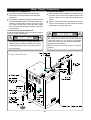
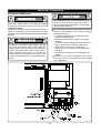
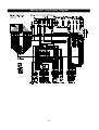
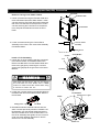
OPERATOR'S MANUAL
C
Natural Gas (NG)-Factory Default
Liquid Propane Gas (LPG)-Optional Conversion
Model GU32
Model GU28
Model GU26
Model GU20
/
/
/
/
501(11,12,21,22)1321
501(11,12,21,22)1281 (Optional)
501(11,12,21,22)1261
501(11,12,21,22)1201 (Optional)
Service Information Center:
!
!
Read this Operator's Manual carefully and be sure
your Water Heater is properly assembled, installed
and maintained. Failure to follow these instructions
exactly could result in a fire or explosion, serious
bodily injury and/or property damage.
Call us first if you have any questions with this
product. We can help you with questions about
assembly and Water Heater operation or if there
are damaged or missing parts when you unpack
this unit from the shipping box. Please call before
returning to the store.
Do not store or use gasoline or other flammable
vapors and liquids in the vicinity of this or any other
appliance.
1- 866- 946- 1096
8am-4:30pm CST, Monday through
Friday
!
IMPORTANT:
WARNING
!
WHAT TO DO IF YOU SMELL GAS
1. Do not try to light any appliance.
2. Do not touch any electrical switch; do not use
any phone in your building.
3. Immediately call your gas supplier f rom a
neighbor's phone. Follow the gas supplier's
instructions.
4. If you cannot reach your gas supplier, call the fire
department.
Ÿ Only specially trained and authorized
personnel are permitted to service this
water heater.
Ÿ NOTE TO ASSEMBLER / INSTALLER:
Leave this manual with the consumer.
Ÿ NOTE TO CONSUMER:
Keep this manual for future reference.
Ÿ RECORDYOURSERIAL
WARNING
!
#__________________
(see silver CSA label on Gas Water Heater)
WARNING
!
California Proposition 65 lists chemical substances
known to the state to cause cancer, birth defects,
death, serious illness or other reproductive harm.
This product may contain such substances, be
their origin from fuel combustion (gas, oil) or
components of the product itself.
157020132 Date 2009/8/5
1
Table of Contents
!
CAUTION
WARNING
WARNING
!
Primary Safety Warning...............................1-3
Pre-Installation Instructions...............................3
Parts Diagram and List for GU28/GU32....4-5
Parts Diagram and List for GU20/GU26....6-7
Operating Instructions.................................8-9
Use & Care Instructions
• Maintenance and Service............................10
• Troubleshooting............................................. 11
• Specifications................................................12
• Installation................................................13-24
• Gas Supply Piping....................................25
• Water Supply Connection...................26-27
• Electrical Connection............................28-30
• Liquid Propane Gas Conversion.........31-32
• Plumbing Diagrams.................................33-34
• Warranty Terms..........................................35
!
If you detect abnormal combustion or abnormal odors, or an earthquake, tornado or
fire:
1. Turn off the hot water supply at the faucet.
2. Turn off the power to the hot water heater by
unplugging.
3. Turn off gas and water at the manual shut-off
valves.
4. Consult the nearest service personnel.
This will help prevent fire, electrical shock or
damage to the unit.
WARNING
!
!
DO NOT place combustible chemicals or
materials such as laundry, newspapers, hair
spray, spray detergent, oil, gasoline, benzene
etc., near the water heater or the exhaust vent
terminal.
!
If you do not follow these instructions exactly,
a fire or explosion could result causing property
damage, personal injury or loss of life.
LEAVE the proper clearance between the
water heater and nearby objects (trees, timber,
boxes and flammable materials etc...)
BE SURE to electrically ground the unit.
!
WARNING
DO NOT touch the power cord with wet hands.
!
KEEP power cord free of dust.
DO NOT use a broken or modified power cord.
Do not install water heater where flammable
products will be stored.
DO NOT bind, bend or stretch power cord.
Read and follow the water heater warnings and
instructions. If the operator's manual is missing,
contact the retailer or manufacturer.
DO NOT connect the water heater to a solar
water heater.
CAUTION
!
DANGER
!
!
WARNING
!
Never use this hot water heater unless it
is completely filled with water.
_ Hot water temperature over 125 F can cause
severe burns instantly or death from scalding.
_ Children, disabled and elderly are at the highest
To prevent damage to the tank, the tank must be
filled with water. Water must be running from the
hot water faucet before turning the main gas valve
to the water heater to "ON".
risk of being scalded.
_ Temperature limiting valves are available, ask
your service professional.
_
Check the temperature of the running hot water
by hand before taking a shower.
_
Check to see that the gas supplied matches
the gas type on the rating plate.
Turning Off The Appliance:
1. Turn off all electrical power by unplugging the power
cord from the outlet if service is to be performed.
2. Turn the gas shut-off valve located separately of
the water heater to the OFF position.
WARNING
2
Pre-Installation Instructions for Your Safety
!
WARNING
TO TURN OFF GAS TO WATER HEATER
1. Turn off all electrical power to the water heater if service is to be performed.
!
If you do not follow these instructions exactly,
a fire or explosion could result causing property
damage, personal injury or loss of life.
2. Turn the manual gas valve located on the outside of the
unit clockwise to the off position.
Installation Codes
_
The installation must conform with local codes or, in
the absence of local codes, with National Fuel Gas
Code, ANSI Z223.1/NFPA 54.
_
Properly ground the unit in accordance with all local
codes or in the absence of local codes, with the National Electrical Codes, ANSI/NFPA 70.
A. This water heater does not have a pilot. It is equipped
with an ignition device that automatically lights the
burner. Do not try to light the burner by hand.
Vapors from flammable liquids will explode and
catch fire causing death or severe burns
Do not use or store flammable products such as
gasoline, solvents or adhesives in the same room or
area near the water heater.
B. BEFORE OPERATION smell all around the water
heater area for evidence of leaking gas. Be sure to
smell next to the floor because gas is heavier than
air and will settle on the floor.
WHAT TO DO IF YOU SMELL GAS
Keep flammable products
1. Far away from water heater
2. In approved containers
3. Tightly closed
4. Out of children's reach
Do not try to light any appliance.
Do not touch any electrical switch.
Do not use any phone in your building.
- Immediately call your gas supplier from a neighbor's
phone. Follow the gas supplier's instructions.
- If you cannot reach your gas supplier, call the fire
department.
Vapors
1. Cannot be seen
2. Vapors are heavier than air
3. Go a long way on the floor
4. Can be carried from other rooms to the main burner
by air currents
C. Use only your hand to turn the gas valve knob. Never
use tools. If the knob will not turn by hand, don't try
to repair it. Call a qualified service technician. Force
or attempted repair could result in a fire or explosion.
WARNING: Do not install water heater where flammable products will be stored.
D. Do not use this water heater if any part has been
under water. Immediately call a qualified service technician to inspect the water heater and to replace any
damaged parts.
Read and follow the water heater warnings and
instructions. If the operator's manual is missing,
contact the retailer or manufacturer.
OPERATION INSTRUCTION
1. STOP! Read this safety information above and in this
Operators Manual.
The hot water outlet temperature of the water heater
is factory set 122 F (50 C).
WARNING: Use this water heater at your own risk.
The set outlet water temperature can cause severe
burns instantly or death from scalds. Test the water
before bathing or showering. Do not leave children or
the infirm without supervision.
2. Turn off all electrical power to the water heater.
3. Do not attempt to light the burner by hand.
4. Turn the manual gas valve located on the outside of
the unit to the off position.
5. Wait five (5) minutes to clear out any gas. If you smell
gas, STOP! Follow "B" in the safety information above.
If you don't smell gas, go to next step.
6. Turn the manual gas valve located on the outside of
the unit to the ON position.
7. Turn on all electrical power to the water heater.
8. If the water heater will not operate, follow the instruc-
tion "To Turn Off Gas Water Heater" and call your
service technician or gas supplier.
3
Parts Diagrams for Model GU28,32 / 501(11,12,21,22)1(28,32)1
4
Parts List for Model GU28,32 / 501(11,12,21,22)1(28,32)1
KEY
DESCRIPTION
Part #
QTY
1
Panel, Front
302040001
1
2
Panel, Rear
302040002
1
3
Panel, Left
302040003
1
4
Panel, Right
302040004
1
5
Panel, Top/Front
301040005
1
6
Panel, Top/Rear
301040006
1
7
Panel, Bottom
151010009
1
8
Control Panel Assembly
301080170
1
9
Temperature and Pressure Relief Valve
194010281
1
10
Exhaust Collar Assembly
301070230
1
11
Drain Valve Assembly
305070273
1
12
Plug
601020001
2
13
Power Wire Assembly
192010143
1
14
Water Fitting Cap
155010059
4
15
Exhaust Flange
307040540
1
16
Packing, Top
152010227
1
17
Drain Cap
155010288
1
Part #
QTY
301080190
1
Optional Parts For Outdoor Model
KEY
DESCRIPTION
18
Vent Cap Assembly ( Exhaust Top Included)
Optional Parts For Horizontal Venting Termination
KEY
DESCRIPTION
19
Side Vent Terminator
5
Part #
QTY
151010187
1
Parts Diagrams for Model GU20,26 / 501(11,12,21,22)1(20,26)1
6
Parts List for Model GU20,26 / 501(11,12,21,22)1(20,26)1
KEY
DESCRIPTION
Part #
QTY
1
Panel, Front
301040001
1
2
Panel, Rear
301040002
1
3
Panel, Left
301040003
1
4
Panel, Right
301040004
1
5
Panel, Top/Front
301040005
1
6
Panel, Top/Rear
301040006
1
7
Panel, Bottom
151010009
1
8
Control Panel Assembly
301080170
1
9
Temperature and Pressure Relief Valve
194010281
1
10
Exhaust Collar Assembly
301070230
1
11
Drain Valve Assembly
305070273
1
12
Plug
601020001
2
13
Power Wire Assembly
192010143
1
14
Water Fitting Cap
155010059
4
15
Exhaust Flange
153010226
1
16
Packing, Top
152010227
1
17
Drain Cap
155010288
1
Part #
QTY
301080190
1
Optional Parts For Outdoor Model
KEY
DESCRIPTION
18
Vent Cap Assembly ( Exhaust Top Included)
Optional Parts For Horizontal Venting Termination
KEY
DESCRIPTION
19
Side Vent Terminator
7
Part #
QTY
151010187
1
Operating Instructions
NORMAL OPERATION
To turn on your water heater
STARTING THE SYSTEM
For your safety, read before operating
This water heater does not have a pilot. It is equipped
with an ignition device which automatically lights the
burner. Do not try to light the burner manually.
1. Open a hot water tap.
Before operating, make sure that a gas leak is not
evident by smelling the area around the unit. Be
sure to smell next to the floor because gas is heavier
than air and will settle on the floor.
3. Mix cold water to get the desired water temperature
2. Burner will ignite; the indicator will light on front
controller.
at tap.
4. Maximum temperature of hot outlet can be set by
controller on the front of the unit.
Use only hand to turn the gas valve knob. Never use
tools. If the knob will not turn by hand, do not try to
repair it, call a qualified service technician. Force or
attempted repair could result in a fire or explosion
due to the gas leakage.
Do not use this water heater if any part has been
under water. Immediately call a qualified service technician to inspect the water heater and to replace any
parts that have been under water.
Do not install the unit standing directly on
combustible surface.
To turn off your water heater
WHAT TO DO IF YOU SMELL GAS
1. Close the hot water tap and the water heater's burner
-Do not try to light any appliance.
-Do not touch any electrical switch.
-Do not use any phone in your building.
- Immediately call your gas supplier from a neighbor's
phone. Follow the gas supplier's instructions.
- If you cannot reach your gas supplier, call the fire
department.
will turn off automatically.
STARTING UP
Once the unit has been properly installed, check the
gas and water connections for leaks.
Check for proper ventilation and combustible air supply
to the water heater. Purge the gas and water lines to
remove debris; then follow these steps to turn on your
unit.
!
1. Close the manual gas shut-off valve located on the
gas line.
CAUTION
!
Never use this hot water heater unless it
is completely filled with water.
2. Fully open the manual water shut-off valve on the wa-
ter supply line.
The tank must be filled with water. Water must
flow from the hot water faucet before turning "ON"
gas to the water heater.
3. To ensure complete filling of the heat exchanger tank,
allow air to exit by opening the nearest hot water
faucet. Allow water to run until a constant flow is obtained. This will let air out of the water heater and
piping.
!
4. Open a hot water tap to check that water will flow to
that tap. Then close the hot water tap.
CAUTION
!
Do not drink water that has been inside
the unit for extended period of time. Do
not drink the first use of hot water from
the unit in the morning.
5. Fully open the manual shut-off gas valve.
6. Plug in the 120 VAC/60Hz power supply to the water
heater and turn on the unit.
7. Open tap and enjoy endless hot water!
8
How To Use The Front Control Interface
1. To switch the water heater ON: from OFF condition
Press the Power Button.
-The temperature selected will be indicated on the
Digital Monitor.
-The ON Indicator will light up.
2. When running the water by opening the water tap,
the water heater will start the burner automatically
and the Digital Monitor will show the actual water
temperature. When water taps are closed, the unit
will stop the burner and the Digital Monitor will show
the set temperature.
To switch the water heater OFF:
1. Press the Power Button.
-The temperature selected on the Digital Monitor will
go out.
-The ON Indicator will turn off.
To adjust water temperature:
1. Press the "HOT" or "COLD" Temperature Setting
Button with unit ON. (Temperature setting is only
adjustable when the water heater is not in use.)
2. The maximum water temperature setting can be
limited by DIP switches. This manual setting overrides
adjustable temperature settings on the front panel.
Please call Grand Hall USA for DIP switch setting
instructions if needed.
9
!
DANGER
!
_
Hot water heater temperature over 125 F can
cause severe burns instantly or death from
scalding.
_
Children, disabled and elderly are at the highest
risk of being scalded.
_
Feel water temperature before bathing or showering.
_
Temperature limiting valves are available, ask a
professional person.
W a te r Te m pe ra ture Tim e to Produc e a Serious Burn
1 20 ℉
Mo re tha n 5 m inu tes
1 25 ℉
1 .5 to 2 m in u te s
1 30 ℉
Abo u t 30 s e con d s
1 35 ℉
Abo u t 10 s e con d s
1 40 ℉
L es s tha n 5 s e co n ds
1 45 ℉
L es s tha n 3 s e co n ds
1 50 ℉
Abo u t 1.5 s eco nd s
1 55 ℉
Abo u t 1 s e co nd s
Sediment Build-up: Unlike a typical storage tank,
this heater has a self cleaning system initiated
by the flow of water. Build up of sediment in faucet
aerators, shower heads and screens could impair
water flow and cause the water heater to deliver
less than its full output, or to shut down completely.
Check any of these screens or shower heads on
your faucets periodically and clean as necessary.
Maintenance and Service
!
WARNING
!
Turn off the electrical power supply, the manual
gas control valve, and the manual water control
valve before servicing.
BURNER IGNITION: Water heater has automatic ignition system. Once you open a hot water tap, the
computer electronically ignites the burners. You can
see the burner flame via flame inspection hole.
SYSTEMS AND PARTS CHECK
The unit should be checked once a year or as necessary by a certified and trained technician. If repairs are
needed, the repairs should be done by a certified and
trained technician.
The following systems and parts should be checked at
least once a year.
1. Venting system
2. Burner
3. Manual operation of the pressure relief valve to ensure correct operation.
4. Periodic cleaning of the water strainer.
5. Remove the thermistor from heat exchanger and
check for mineral coating. A mineral coating on the
thermistor requires cleaning.
Physical Damage: If the water heater has been subjected to fire, flood, or physical damage, turn off the
manual gas shutoff valve and do not operate the water heater again until it has been checked by qualified personnel.
Flame Inspection
Hole
!
Temperature Setting: Hotter water increases the
risk of scalding injury.
CAUTION
!
Avoid contact with hot water released from
the relief valve.
Venting System Inspection: A visual inspection
should be made on the venting system at least once
a year.
_
Be sure the venting is properly connected to prevent escape of dangerous flue gases which could
cause deadly asphyxiation.
_
Obstructions could cause improper venting. The
combustion and ventilation air flow must not be
ob-structed.
_
Damage or deterioration which could cause improper v enting or leakage of combustion
byproducts.
NO LUBRICATION: No lubrication is required for
the water heater.
Service & Cleaning Of The Burner: Only specially
trained and authorized personnel are permitted to service the burner.
Clean Up: The flue outlet and the air intake holes on
the bottom sides of the water heater should be checked
frequently. Clean as needed to prevent the entry of
water, insects, rodents or other foreign materials such
as fallen leaves and dust that could cause blockages.
Do not obstruct the flow of combustion air and exhaust air flow.
Water Strainer: The water strainer should be
checked at least once a year. It protects valve from
dirt, and pipe scale. Self-clean by opening valve
or plug connected to a blow-off outlet.
10
Troubleshooting
TROUBLESHOOTING
This unit has the ability to check its own operation continuously. If an error occurs, a message will flash on the digital
monitor of the front panel.
This assists with diagnosing the error, and may enable you to overcome a problem without a service call. Please
quote the code displayed when inquiring about service.
Code Displayed
Fault
Remedy
E1
E2
E3
E4 / E5
E6 / E7
E8 / E9
E11
E12
E13
E14
E15
E16
E17 / E18
E19 / E20
E21
E22
E24
E27
E28
E30 / E31
E34
E35
E36
E37
E38
E39
E40
E41
E42
E43
E46
Remaining flame detected
Ignition failure
Weak flame or abnormal combustion
An outlet thermistor open/short
A H/E thermistor open/short
An inlet thermistor open/short
A DC motor failure
Water temperature too hot
No filled water in tank or pressure switch failure
A controller failure concerning an inlet thermistor
A controller failure concerning a H/E thermistor
A controller failure concerning an outlet thermistor
A burner thermistor short/open
A secondary air hole thermistor short/open
A vent condition is not normal
Temperature too high on a burner thermistor
Mixing control valve is not connected
Mixing control valve initialization failure
Power line of main gas valve is open
Rotation of a DC fan is too high/low
Carry over gas valve is not connected
Modulation gas valve is not connected
A controller failure concerning gas valve
Communication failure with SUB CPU
Subsidiary RAM failure
A controller failure concerning Subsidiary flame signal
Main RAM failure
A controller failure concerning flame signal
Main ROM failure
Main MUX error
Detection of Oxygen depletion
Call service center
Check gas line, igniter, flame rod
Gas line not supplying enough gas
Check outlet thermistor and wiring
Check H/E thermistor and wiring
Check inlet thermistor and wiring
Call for replacement motor
Check flow sensor or CPU
Check water tank or pressures witch
Call service center
Call service center
Call service center
Check burner thermistor and wiring
Check air hole thermistor and wiring
Check vent condition for backflow
Call for replacement thermistor
Check mixing valve wiring
Call for replacement valve
Check wiring, thermostat and fuse
Call for replacement motor
Check carry over gas valve wiring
Check modulation gas valve wiring
Call service center
Call service center
Call service center
Call service center
Call service center
Call service center
Call service center
Call service center
Call service center
NOTE: In all cases you may be able to clear the Error Message simply by turning the hot water tap OFF, then ON
again. If this does not clear the Error Message, try pushing the ON/OFF button OFF, then ON again. If the Error
Message still remains, contact our service center or your nearest service agent and arrange for a service call.
1- 866-946-1096
8am-4:30pm CST, Monday through Friday
11
Eternal Hybrid Water Heater Technical Specifications
Model Name
GU20 (Optional)
GU26
Model Number (CSA)
501(11,12,21,22)1201
501(11,12,21,22)1261
Installation
Type
GU28 (Optional)
GU32
501(11,12,21,22)1281
501(11,12,21,22)1321
Indoor or Outdoor
Flue system
Forced Exhaust Power Vent
Operation
With or Without Remote Controls
Direct Electronic Ignition and Automatic Flame Sensing
Ignition
Gas Valve Type
Current Controlled Double Stage Negative Pressure Full Modulation Gas Valve
Burner System
Single Orifice Fuel Injection Pre-Mixing Cylindrical Metal Fiber Infrared Burner w/Full Modulation
Min
Gas Input
Max
Orifice Size
47,500 BTU/Hr
145,000 BTU/Hr
180,000 BTU/Hr
NG
7.0mm
LP
5.2mm
6.5mm
3.5 - 10.5 "WC
LP
Manifold Pressure
8.0 - 14 "WC
Min
0.9 "WC
0.9 "WC
0.5 "WC
0.5 "WC
Max
1.6" WC
2.4 "WC
1.8 "WC
2.5 "WC
105mA
131mA
107mA
126mA
0.1 - 17.5gpm
0.1 - 20.8gpm
Maximum Valve Current
CO
Under 100PPM
NOx
Under 55PPM
Flue Temp
Under 185F
Combustion
Analysis
236,000 BTU/Hr
9.0mm
NG
Gas Supply
Pressure
199,000 BTU/Hr
15 to 150Psi
Operating water pressure
Flow Capacity Range
0.1 - 12.8gpm
0.1 - 15.8gpm
Water Flow Sensing
Water Flow Sensor w/Built-in Display
Water Temperature Sensing
Tank Thermistor, Inlet Thermistor, Outlet Thermistor, Burner Thermistor, Air Thermistor
Water Temperature Control
Simulation Feedforward and Feedback w/Electronically Controlled Mixing Valve
Water Holding Capacity
3.8 gal
6.4 gal
Thermal Efficiency
86%
Temperature Settings
100,102,104,106,108,110,112,114,116,122,131,140 (default),149,158,167 (15 steps)
Packaged Weight (lbs)
166.1
196.2
Unit Weight (lbs)
145.6
172.9
Maximum Noise Level
48db
60db
120 Volts 60 Hz
Electrical Power Supply
Electrical Consumption
Standby - 8 watts, Maximum - 84 watts
Standby - 8 watts, Maximum - 105 watts
Package Dimensions (WxHxD)
20.5 x 38.3 x 24.8
20.5 x 45.7 x 24.8
Unit Dimensions (WxHxD)
17.3 x 33.5 x 22.8
17.3 x 40.9 x 22.8
Gas
Connections
Cold water
3/4 inches NPT Female
Hot water
Safety Devices
T&P Valve, Flame Rod, Thermal Fuse (307F), Remaining Flame Detector, Fan RPM Detector, Freeze
T&P Valve, Flame Rod, Thermal Fuse (307F), Remaining Flame Detector, Fan RPM Detector, Freeze Protection (Protection (-4F), Vent Blockage Detection, Thermostat Switch (194F), Thermostat Switch (221F),
4F), Vent Blockage Detection, Thermostat Switch (194F), Thermostat Switch (221F), Ignition Prevention, GFCI
Ignition Prevention,
GFCI w/3A
Leakage
Breaker
w/3A
fuse,
MixingMaximum
Valve, User
Selectable
Leakage Breaker
fuse, Mixing
Valve,
User
Selectable
Temperature
Lock Maximum
Temperature Lock.
12
Installation Preparation
2. If vented through an outside wall or through the roof
PROFESSIONAL INSTALLATION REQUIRED
Only specially trained and authorized technicians
are permitted to service this water heater.
using 4" vent piping the total vent run cannot exceed
35 feet with one 90 elbow. If more elbows are required the venting distance must be reduced 5 feet
for every 90 elbow.
Unpacking Your Eternal Water Heater
Unpack the unit carefully and make sure that all
accessories are put aside so that they will not
be lost.
Ÿ Operator's manual
3. Vent piping should slope downward towards the out-
side if condensate collector is not used. Horizontal
runs require adequate support at 3 1/ 2 feet intervals
and vertical runs supported at 5 feet intervals.
Ÿ Warranty Card
Ÿ Additional Parts
4. Condensation may be created at times as the com-
bustion gases exit the vent cap. Discoloration of surfaces in proximity to the vent cap may occur.
Inspect the water heater for possible shipping
damages.
Additional Safety Instructions
Check the markings of the rating plate on the water
heater to be certain the type of gas being furnished
corresponds to what the water heater is equipped
for.
Do not connect this water heater to a fuel type not
in accordance with the rating plate
1. Read the Safety guidelines in the beginning of
this manual.
!
CAUTION
!
Before commencing the Installation
Check that it is in accordance with relevant
building and mechanical codes, as well as any
local or state or federal regulations.
!
2. The internal computer controlled regulator is pre-
WARNING
!
Ÿ For
set by the manufacturer and should not be adjusted by user.
other than direct vent appliance, the
appliance must be located as close as possible
to a chimney or gas vent.
3. Maintain proper space around the unit for servic-
ing. Install the unit so that it can be connected
or removed easily.
Ÿ The
appliance should be located in an area
where leakage of the tank or connections will
not result in damage to the area adjacent to
the appliance or to lower floors of the structure.
When such locations cannot be avoided, it is
recommended that a suitable drain pan be
installed under the appliance. The pan must not
restrict combustion air flow.
4. The electrical connection requires a means for
switching off the power supply.
5. Avoid installing the unit in an area with high lev-
els of dust, sand, or debris. These particles may
clog the air vent or impair the function of the fan,
leading to improper combustion. Regular maintenance is needed.
Ÿ The minimum inlet gas pressure must be within
the value specified by the manufacturer and the
minimum value listed is only for the purpose
of input adjustment.
6. Do not install the unit where the exhaust vent is
pointing into any opening in a building or where
the noise may disturb neighbors.
WATER HEATER PLACEMENT
Ÿ If
a water heater is installed in closed water
supply system, such as one having a backflow
preventer in the cold water supply line and a
thermal expansion tank is required, contact the
water supplier or local plumbing inspector on
how to control this situation.
Carefully choose the location for the new heater as
placement is a very important consideration for the
safety of the occupants in the building and for the
most economical use of the appliance.
Ÿ The Temperature and Pressure (T&P) relief valve
Whether replacing an old water heater or putting
the water heater in a new location, consider the
following critical points:
must be certified as meeting the requirement of
the Standard for Relief Valves and Automatic Gas
Shut-off Devices for Hot Water Supply Systems
ANSI Z21.22/CAN1-4.4. The valve must be marked
with a maximum set pressure not to exceed the
marked hydrostatic working pressure of the water heater (150 psi) and a discharge capacity not
less than the water heater input rate as marked
on the rating plate.
1. The location selected should be as close to the
vent termination point as possible, and centered
within the water piping system for best hot water delivery. All water heaters can leak. Do not
install without adequate drainage provisions
where water flow can cause property damage.
Ÿ For
tank type water heaters, the relief valve
must be installed near the hot water outlet.
13
T&P Valve and Exhaust Collar Installation
1. Loosen 2 screws holding the Front Panel at the
bottom, push the panel down and towards yourself
to remove. Take the accessory box out of the front
of the unit. This box contains:
T&P Relief Valve x 1
Exhaust Collar x 1
O Ring (G95) x 1
Mesh Screen x 1
Drain Cap x 1
Self Tapping Screw (T4x16) x 5
2. Attach the Front Panel and push the panel up.
Secure with the previously removed screws.
3. Prior to installing the Exhaust Collar, please
secure the O-Ring between the Exhaust Flange
and botton of Exhaust Collar with T4 screws.
14
T&P Valve and Exhaust Collar Installation
4. Install the Exhaust Collar and secure with M4
screws.
5. Install the T&P Relief Valve on the side of unit.
Make sure the T&P Relief is secured to prevent
water leak.
Vent Cap Installation (For Outdoor Installation)
1. Install the Vent Cap on the Exhaust Top. Secure
the Vent Cap by using clamp or screw on the
Exhaust Top.
15
Outdoor Installation
STANDING INSTALLATION
This unit is to be installed on a floor.
Do not install the unit standing directly on combustible surface.
OUTDOOR INSTALLATION
Installation Codes :
Follow all local codes, or in the absence of local codes,
follow the codes for installation of gas burning appliances;
National fuel gas code ANSI Z221.23. For outdoor installation, do not remove the vent cap from the top of the appliance.
Locate the water heater in an open, unroofed area, and
maintain the following minimum clearances from combustible materials.
Clearances
OUTDOOR
INDOOR
A -- From
of of
water
heater
Fromtop
top
water
heater
24 inches
36 inches
B -- From
of unit
Fromfront
front
of unit
24 inches
4 inches
--
6 inches
D
of of
unitunit
D --From
Fromback
back
2 inches
2 inches
EL --From
side
of unit(gas
pipingpiping
side) side)
Fromleft
left
side
of unit(gas
12 inches
6 inches
ER --From
side
of unit
Fromright
right
side
of unit
2 inches
2 inches
combustible
combustible
C -- From
flueflue
or vent
connector
in anyindirection
Fromside
sidewall
wall
or vent
connector
any direction
FL --Floor
Floor
If this unit is installed under an overhang, there must be a
24" clearance from the top of the unit to the overhang, and
the surrounding area must be open in front and on the sides
of the unit.
!
WARNING
!
Do not install the water heater where water,
debris or flammable vapors may get into the flue
terminal. This may cause damage to the water
heater.
!
WARNING
!
Do not install the heater vent terminator within
4 ft. of any air intake opening into any building.
Similar Canadian regulations forbid the unit from
being installed within 10 ft. of any opening into any
building.
!
WARNING
!
!
DANGER
!
Improper installation can cause nausea or asphyxiation from carbon monoxide and flue gases
which could result in severe injury or death. For
installation in altitudes above 4,500 feet, contact
the manufacturer for installation instructions.
Do not have the flue terminal pointing toward an
opening into the building. Do not locate your
heater in a pit or any location where gas and
water can accumulate.
16
Maintenance and Service Indoor Installation
Air supply from outside building:
When combustion air is supplied directly through an
outside wall such as intake louvers openings into the
dwelling, each opening should give a minimum free
area of one square inch per 15,000 Btu/hour of the
total input ratings of all appliances in the enclosed
area.
INDOOR INSTALLATION
Install 4" vent pipe directly on flue outlet.
Combustion Air Supply:
The water heater should be located in an area where
enough air is available for proper combustion and
ventilation of the surrounding area. Follow the latest
edition of ANSI Z223.1 and any your local codes that
are applicable.
Eternal is a Category III vented appliance and
manufacturer's ventilation specifications should be
followed.
In general these requirements specify that if the unit
is installed in a confined space, there must be permanent air supply openings.
MINIMUM RECOMMENDED AIR SUPPLY TO
WATER HEATER
Water heater capacity
Outside air area
Inside air area
Max. 236,000 BTU
16 sq.in.
64 sq.in.
Max. 199,000 BTU
14 sq.in.
54 sq.in.
Max. 180,000 BTU
12 sq.in.
48 sq.in.
Max. 145,000 BTU
10 sq.in.
40 sq.in.
Air supply from inside building:
When combustion air is supplied from inside the building, each opening should give a minimum free area of
one square inch per 3,750 Btu/hour of the total input
ratings of all appliances in the enclosed area. These
openings should never be less than 40 sq.in.
INSTALLATION DIAGRAM
64sq.in. each for GU32/501(11,12,21,22)1321
54sq.in. each for GU28/501(11,12,21,22)1281
48sq.in. each for GU26/501(11,12,21,22)1261
40sq.in. each for GU20/501(11,12,21,22)1201
!
CAUTION
WARNING
The minimum required inside air volume should be 50
cu.ft per every 3,750 Btu/hour.
!
Water Heater Capacity Minimum Required Air Volume
Improper installation can cause nausea or asphyxiation from carbon monoxide and flue gases
which could result in sever injury or death. For
installation in altitudes above 4,500 feet, contact
the manufacturer for installation.
17
Max. 236,000 BTU
3,150 cu.ft
Max. 199,000 BTU
2,655 cu.ft
Max. 180,000 BTU
2,400 cu.ft
Max. 145,000 BTU
1,950 cu.ft
Mounting Procedure for Commercial / Foodservice
Description:
In compliance with NSF-5 standard,water heaters
should be mounted in a way that seepage cannot
accumulate under the unit. Grand Hall recommends
either applying watertight caulking along the bottom
edge of the unit with the floor surface, or install Eternal in conjunction with a water heater stand or platform that would raise the unit at least 6”off the floor.
Caulking Method:
Apply caulking along the bottom edge of the unit.
Make sure the caulk is water tight and applied evenly
between unit and flat surface to prevent seepage from
accumulating underneath the unit.
Mounting on raised platform or stand:
Install the unit on a water heater stand that raises
the unit at least 6” from the floor where seepage can
accumulate underneath the unit.
18
Condensate Drain Installation
CONDENSATE DRAIN REQUIREMENTS
VERTICAL TERMINATION
HORIZONTAL TERMINATION
Condensate formation can occur in high efficiency power vent appliances. To prevent condensate damage, a condensate drain must be installed under the following conditions:
All vertical terminating vent installations.
Horizontal terminating vent installations if a vertical rise in the vent system exceeds 5 ft. If more than one elbow is
used in the vertical section, a condensate collector must be used.
When the condensate collector is used, please follow these instructions.
The Exhaust Collar of this water heater has a built-in condensate collector. Use 1/2" ID vinyl tube to connect
condensate drain port. Do not use copper piping for any portion of the condensate drain.
The condensate trap must contain a minimum of 3 inches of water.
Dispose of condensate per local codes.
Horizontal Termination Without Using The Condensate Collector
!
WARNING
The condensate collector must be used in horizontal
teminations if a vertical rise in the vent system exceeds
5ft.
!
Regions of cold climate will create more condensate in
the vent system. The condensate collector should be
used in cold climates.
If the condensate collector is not used, the drain
pipe must be capped to prevent exhaust gases
and condensate from entering the building. The
Drain Cap is supplied on the appliance.
If more than one elbow is used in the vertical section
the condensate collector must be used.
19
Exhaust Venting Installation
EXHAUST VENTING INSTALLATION
Exhaust Fans and Ventilation
The water heater is equipped with a combustible air
detector to measure whether there is enough air for
proper combustion. If there is not, the water heater
will not work until sufficent air is provided.
Any equipment, which uses air from an enclosed
space, can deplete the air from that area. This can
result in exhaust flowing from the flue to the enclosed
space, which could result in the accumulation of
dangerous exhaust fumes in the space where the
water heater is installed.
Additional air must be supplied to compensate for
any exhaust effect.
If a fan blower is used to supply air to the water heater
room, the installer should make sure it does not create drafts, which could cause unwanted shutdowns.
If a blower is necessary to provide adequate combustion air to the water heater, a switch or equivalent device must be wired into the water heater control to prevent the water heater from firing unless the
blower is operating.
VENTING INSTRUCTION
This water heater must be vented in accordance with
"Venting of Equipment" section of the latest edition
of the National Fuel Gas Code, ANSI Z223.1 and all
aapplicable local building codes.
!
WARNING
VENTING CONNECTION
The vent system must be gas tight. All seams and
joints must be sealed with silicone sealant or adhesive tape having a minimum temperature rating of
400 F.
When installing the vent system, all applicable national and local codes must be followed. If thimbles,
fire stops or other protective devices are going to be
installed which will penetrate any combustible or
noncombustible construction, be sure to follow all
applicable national and local codes.
Fan assisted appliances: Follow the requirement as
indicated in the latest edition of ANSI Z233.1/NFPA
54.
Horizontal exhaust vent connectors must pitched
downward to the terminal if condensate collector is
not used, at least 1/4" per foot of length. Single wall
vent connectors must be at least 6" from adjacent
unprotected combustible surfaces. Joint of vent connectors should be securely fastened by sheet metal
screws or other approved method.
VENTING LENGTH
The entire vent system must not exceed the size
specified in table.
Diameter
4 inches
Max. No. of Elbow
3 ea
Max. Vertical or Horizontal run in Length 40 ft
For each elbow added, deduct 5 feet from maximum vent length. For example, 30 ft. is the maximum total distance if two elbows are used.
When the horizontal vent run exceeds 5 feet the
following criteria must be observed:
Ÿ Support the vent run at 3 feet intervals with overhead hanger.
Ÿ Pitch down the vent run toward the vent terminal
at a rate of 1/4 inch per every foot of horizontal
run if condensate collector isn't used.
!
Improper venting of this appliance can result in
excessive levels of Carbon Monoxide, which can
cause severe personal injury or death.
General rules for venting system
1. Place the water heater as close as possible to the
vent.
2. The vent collar on the water heater must be fastened
VENTING CLEARANCES
Ÿ 12" minimum from the ground, 9" from ceiling overhangs.
Ÿ The power vent outlet terminal shall terminate at
least 36" above any forced air inlet located within
10 feet.
Ÿ The power vent outlet terminal shall terminate at
least 4 feet below, 4 feet horizontally from or 1
foot above any door, window or gravity air inlet
into the building.
directly to an unobstructed vent pipe.
3. Do not weld the vent pipe to the water heater collar.
The weight of the stack must not rest on the water
heater. The flue must be easily removable for normal service and inspection of the unit.
4. The water heater must not share common vent with
a fireplace, wood stove or other appliances.
5. Avoid terminating the water heater vent near any air-
conditioning or air-supply fans.
VENTING TROUGH ROOF-CLEARANCES
Ÿ The power vent outlet terminal shall terminate at
least 12" above the roof surface.
6. Avoid using an oversized vent pipe or using extremely
long runs of the pipe. This may cause excessive
cooling and condensation of flue exhaust gases.
7. The venting system must be installed in a manner
Ÿ
which allows inspection during the installation of the
venting pipes and joints as well as periodic inspection after installation as required by ANSI standards.
20
The location selection must provide clearance
for servicing and proper operation of the water
heater.
Exhaust Venting Installation
This water heater has been design certified by CSA International for use with the specified listed plastic vent
pipe.
CEMENTING PVC, ABS or CPVC PIPE and FITTING
All primers, cleaners and cements must meet all local
codes and applicable standards of the American Society
for Testing Materials.
This water heater must be properly vented for removal
of exhaust gases to the outside atmosphere. Correct
installation of the vent pipe system is mandatory for
the safe and efficient operation of this water heater and
is an important factor in the life of the unit.
Vent pipe installation must be performed in accordance
with state and local codes, or in the absence of such,
the latest edition of National Fuel Gas Code, NFPA 54/
ANSI 223.1. Canadian installations must be performed
in accordance with CAN/CGA-B149.
Before using primers, cleaners and cements, stir or
shake, making sure contents are liquid. Do not use if
found to be lumpy or jelly-like.
1. Cut pipe ends squarely removing all burrs and dirt.
VENT PIPE MATERIAL
Eternal Hybrid Water Heater is a gas burning appliance
with fan-assisted exhaust. The appliance must be vented
with 4" Category III special venting, which is air tight to
prevent leakage of exhaust gases.
2. Dry fit pipe and fittings to be connected for proper fit.
3. Clean pipe and fitting with a primer/cleaner.
4. Apply a thin coat of cement to fitting, avoiding pud-
The appliance must be vented separaely from all other
appliances. The following type of non-metallic vent can
be used:
PVC (schedule 40, ASTM-D1785)
PVC-DWV (ANSI/ASTM-D2665)
CPVC (schedule 40, ASTM-D2846)
ABS (schedule 40, ASTM-D2661)
Sealant (silicon based) is recommended with metallic
venting to ensure proper seal.
*Note : Do not use cellular foam core pipe.
VENT PIPE INSTALLATION
The following guidelines should be followed when installing the exhaust outlet piping:
_
Venting should be as direct as possible with a minimum number of pipe fittings.
_
Venting diameter must not be reduced unless specially noted in the installation instructions.
_
Support all horizontal pipe runs every four feet according to local codes.
_
Vents run through unconditioned spaces where below freezing temperatures are expected should be
properly insulated to prevent freezing. For horizontal runs, wrap the vent pipe with self-regulating 3 or
5 watt heat tape. The heat tape must be U.L. listed
and installed per the manufacturer's instructions.
_
Do not connect this venting system with an existing
vent or chimney.
_
Do not connect common vent with the vent pipe of
any other water heater or appliance.
ding inside.
5. Apply a liberal coat of cement to pipe leaving no voids.
6. Quickly assemble parts while cement is fluid.
7. Push pipe completely into socket of fitting, turning
as it goes until it bottoms.
8. Hold pipe and fitting together for 30 seconds. Then
carefully clean off excess with a cloth. Allow connections sufficient time to cure before disturbing.
9. Remember that vent pipes must be adequately and
securely supported.
CUTTING OPENING THROUGH AN OUTSIDE WALL
AND TERMINATOR INSTALLATION
The 4" PVC, ABS or CPVC Schedule 40 vent pipe can
be run from the water heater through the wall or from the
wall to the water heater, whichever is most convenient.
The vent pipe must extend a minimum of 1.5" through
the exterior wall. Note that inside collars must be slipped
over the vent piping before locating the pipe through the
wall.
Before securing the inside and outside collars to the
wall, use a silicone sealer between pipe and opening to
ensure water and air tight seal.
To prevent condensate from collecting in the venting system slope the vent at a downward pitch of 1/4" per 12 ft.
with condensate trap.
!
The exhaust outlet piping and termination may be installed in one of the following terminations:
1. Standard Horizontal (see page 23)
2. Vertical (see page 23)
NOTICE
!
For installations in Canada,field supplied plastic vent
piping must comply with CAN/CGA B149 1(latest
edition)and be certified to the Standard For Type
BH Gas Venting Systems,ULC S636 Components
of this listed system shall not be interchanged with
other vent systems or unlisted pipe/fittings. All plastic
components and specified primers and glues of the
certified vent system must be from a single system
manufacturer and not intermixed with other system
manfacturer's vent system parts.
The supplied vent connector and vent termination
are certified as part of the water heater.
All pipe, fitting, pipe cement, primers and procedure
must conform to American National Standard Institute
and American Society for Testing and Materials (ANSI/
ASTM) standards in the United States.
21
Vent Pipe Installation & Terminator Position
EXHAUST VENT TERMINATOR POSITION
A re a
D e sc rip tio n s
O th e r th a n D i r e c t V e n t
C le a r a n c e a b o v e g r a d e ,
1 fo o t
v e r a n d a , p o r c h , d e c k , o r b a lc o n y
C le a r a n c e t o w in d o w o r d o o r t h a t 4 f e e t f r o m b e lo w o r
B
s id e o p e n in g . 1 f o o t
m ay be opened
f r o m a b o v e o p e n in g
C le a r a n c e t o p e r m a n e n t ly c lo s e d
C
w in d o w
V e r t ic a l c le a r a n c e t o v e n t ila t e d
s o f f it lo c a t e d a b o v e t h e v e n t
t e r m in a t o r w it h in a h o r iz o n t a l
D
d is t a n c e o f 2 f e e t ( 6 1 c m ) f r o m
t h e c e n t e r lin e o f t h e t e r m in a t o r .
E
C le a r a n c e t o u n v e n t ila t e d s o f f it
F
C le a r a n c e t o o u t s id e c o r n e r
G
C le a r a n c e t o in s id e c o r n e r
C le a r a n c e t o e a c h s id e o f c e n t e r
H
lin e e x t e n d e d a b o v e
m e t e r / r e g u la t o r a s s e m b ly
C le a r a n c e t o s e r v ic e r e g u la t o r
I
v e n t o u t le t
C le a r a n c e t o n o n - m e c h a n ic a l a ir 4 f e e t f r o m b e lo w o r
J
s u p p ly in le t t o b u ild in g t o t h e
s id e o p e n in g . 1 f o o t
c o m b u s t io n a ir in le t t o a n y o t h e r f r o m a b o v e o p e n in g .
C le a r a n c e t o m e c h a n ic a l a ir
K
3 fe e t
s u p p ly in le t
C le a r a n c e a b o v e p a v e d s id e w a lk
L
o r p a v e d d r iv e w a y lo c a t e d o n
7 fe e t
p u b lic p r o p e r t y .
C le a r a n c e u n d e r v e r a n d a , p o r c h
M
d e c k , o r b a lc o n y
F o r c le a r a n c e s n o t s p e c if ie d in A N S I Z 2 2 3 . 1 / N F P A 5 4 ,
p le a s e u s e c le a r a n c e s in a c c o r d a n c e w it h lo c a l in s t a lla t io n
c o d e s a n d t h e r e q u ir e m e n t o f t h e g a s s u p p lie r .
A
Gas meter/Regulater
22
Venting Termination
Venting Material : PVC-DWV(ANSI/ASTM D2665)
VERTICAL VENTING PVC TERMINATION
HORIZONTAL VENTING PVC TERMINATION
Once the v ent terminal location has been
determined, make a hole through the exterior wall
to accommodate the vent pipe. Vent pipe must
exit exterior wall horizontally only.
Insert a small length of vent pipe through the wall
and connect the coupling as shown in above
illustration.
Place the 1/2" mesh metal screen inside the terminal fitting and connect it as shown to the vent
pipe on the exterior of the building.
The location of the vent terminal depends on the
following minimum clearances and considerations
(see illustration)
Seal any opening around the vent pipe or fittings
with mortar or silicone caulk as shown in above
illustration.
Minimum twelve (12) inches above roof.
Complete the rest of the vent pipe installation to
the water heater's exhaust top on the fan outlet.
Minimum twelve (12) inches above anticipated
snow level.
If necessary support horizontal run as previously
mentioned.
Maximum twenty-four(24)inches above roof level
without additional support for vent.
The dome shaped side vent terminator(151010187)
is an accessory designed and provided by Grand
Hall USA specifically for use with Eternal. It has
been designed and thoroughly tested by our engineering staff for use with Eternal.
Four (4) feet from any gable, dormer or other roof
structure with building interior access i.e. vent,
window etc...
Ten (10) feet from any forced air inlet to the building.
Any fresh or make-up air inlet such as a dryer or
fur nace area is considered to be a forced air inlet.
Eternal can be vented straight up and horizontal
section is not required for vertical terminations.
Condensate drain must be used in all vertical
terminations.
23
Checking Gas Combustion Specifications
Model
Manifold Pressure
Min
Max
Gas Supply
Pressure
GU20
0.9 "WC 1.6 "WC
GU26
0.9 "WC 2.4 "WC
GU28
0.5 "WC 1.8 "WC
GU32
0.5 "WC 2.5 "WC NG 3.5~10.5 "WC
GU20DV
0.9 "WC 1.6 "WC
GU26DV
0.9 "WC 2.4 "WC
GU28DV
0.4 "WC 1.75 "WC
GU32DV
0.4 "WC 2.4 "WC
LP 8~14 "WC
Figure 1:
The gas valve is designed with both test ports for gas supply pressure to the unit, and manifold pressure. Refer to
Figure 1 for locations of the test ports on the gas valve.
HOW TO CHECK GAS SUPPLY PRESSURE
1. Turn off power source and turn off gas supply to the
unit.
4. Wait for 10 seconds after the start of standby mode
combustion and check gas supply pressure and manifold gas pressure at the test ports with a manometer.
2. Remove the front cover from the unit.
Check manometer reading of low fire manifold pressure
against unit combustion specifications on p.12. If low
fire manifold pressure needs to be adjusted, loosen the
nut securing the adjustment knob on the bottom of the
gas valve (refer to Figure 1) and adjust to correct setting.
3. Remove the gas supply pressure test port screw and
connect manometer to this port; turn on the gas to
the water heater.
NOTE: Manifold Gas Pressure should only be adjusted on low Fire
4. Turn the water heater on and open multiple taps to
force unit into high fire; check gas supply pressure at
the test port with a manometer with unit in high fire.
NOTE: If gas supply pressure drops below 3.5" WC
unit will not have enough gas volume for max fire!
HOW TO CHECK MANIFOLD GAS PRESSURE
1. While power and gas are off to the unit, open any hot
tap to flush and fill the tank completely with cold water.
NOTE: Recirculation pump must be OFF when
checking Manifold Gas Pressure.
2. Close the running tap and turn power and gas back
on to the unit; set temperature to 131F.
3. The unit should fire up to bring the internal storage
up to set temperature even without any tap open; this
is standby mode.
24
Gas Supply Piping
Check for Gas Leaks
When connections are completed, check for gas
leaks by applying soapy water to all gas fittings and
connections. Presence of soap bubbles foaming is a
sign of gas leaks.
GAS SUPPLY PIPING
NOTE: This unit needs a manual gas control valve
(shut-off valve) that must be connected to the unit
before the gas line.
Check the gas inlet pressure and the type of gas
matching the rating plate located on your water
heater. Also check to make sure your gas meter is
capable of supplying sufficient BTU load to all
appliances. Insufficient gas pressure and volume will
cause your water heater to be deficient in performance
and may not work properly.
This appliance and its individual shut-off valve must
be isolated from the gas supply piping system by
unplugging the unit and turning off the main gas valve
during any pressure testing of the gas supply piping
system at test pressures equal to or less than 1/2
PSI.
Venting Equipment Codes
This water heater must be vented in accordance with
"Venting of Equipment" section of the latest edition of
the National Fuel Gas Code, ANSI Z223.1 and all applicable local building codes.
Always use approved connectors to connect the unit
to the gas line. Always purge the gas line of any
debris before connecting to the heater gas inlet.
Gas Piping System Codes :
Size gas piping system correctly following ANSI Z223.
1/NFPA 54, or by local code.
When measuring the inlet supply pressure, the water heater and all other gas appliances sharing the
gas supply line must be firing at maximum capacity.
Maximum gas pressures must not exceed listed
value.
Low gas pressure could be caused by an undersized
gas pipe, this will cause the water heater's performance to diminish and it would not be able to reach
maximum performance.
Recommended Gas Pipe Size
( Diameter, for Natural Gas)
Distance from gas meter
Pipe size(inches)
0 ft. to 20 ft.
3/4 inch
20 ft. to 60 ft.
1 inch
60 ft. to 100 ft.
1-1/4 inch
NATURAL GAS SUPPLY PIPING
P ip e
s iz e
L eng th
1/2 ”
3/4 ”
1”
1 1/4 ”
1 1/2 ”
2”
C u b ic F e e t o f N a t u r a l G a s
10’
174
363
684
1404
2103
4050
20’
119
249
470
965
1445
2784
30’
96
200
377
775
1161
2235
40’
82
171
323
663
993
1913
50’
73
152
286
588
880
1696
60’
66
138
259
532
798
1536
70’
61
127
239
490
734
1413
80’
56
118
222
456
683
1315
90’
53
111
208
428
641
1234
100’
50
104
197
404
605
1165
125’
44
93
174
358
536
1033
150’
40
84
158
324
486
936
200’
34
72
135
278
416
801
Based on 0.60 specific gravity for natural gas at 0.5 "W.C. pressure drop DOE standard is 1100 BTU per cubic ft. of
natural gas.
PROPANE GAS SUPPLY PIPING
P ip e
s iz e
L eng th
1/2 ”
3/4 ”
1”
1 1/4 ”
1 1/2 ”
2”
K B T U o f P ro p a n e G a s
10’
276
568
1072
2206
3308
6222
20’
190
394
733
1497
2300
4332
30’
153
316
591
1213
1859
3466
40’
130
268
505
1040
1560
2993
50’
115
238
449
914
1418
2647
60’
104
218
410
835
1276
2395
Based on 11 "W.C. supply pressure.
25
70’
97
197
379
772
1182
2206
80’
90
186
347
725
1087
2048
90’
84
174
323
678
1024
1922
100’
79
163
308
631
977
1812
125’
70
147
276
567
867
1607
150’
64
133
253
511
788
1496
200’
56
112
213
440
676
1260
Water Supply Connection
WATER SUPPLY CONNECTION
An approved manual water control valve (water
shutoff valve) must be placed on the cold water
supply line.
AFTER INSTALLATION
After the water heater installation is complete, purge
the water line to remove all the debris and air from
the line. Failure to do so may cause damage to the
heater.
All soldering materials and piping materials must be
suitable with potable water. If the water heater is installed in a closed water system, such as one having a back flow preventer in the cold water supply
line, a safety device must be provided to control thermal expansion.
Troubleshooting Thermal Expansion:
Contact the water supplier or local plumbing inspector
on how to control this situation.
!
WARNING
WARNING
There is a wire mesh filter to trap debris from entering the heat exchanger. This will need to be cleaned
periodically to prolong product life.
!
!
WARNING
!
Be careful not to reverse the hot water outlet and
cold water supply line connections to the water
heater. This will cause your heater to operate dangerously and void warranty.
Use only brass connection nipples. Connecting
different types of metals with water flow creates
electrolysis (battery effect). Such effect will rust
the connections.
Make sure the hot and cold lines are connected
properly.
Typical Installation
2 73
26
Water Supply Connection
PRESSURE RELIEF VALVE
!
CAUTION
Water pipe line joint:
Pipe joint sealing compound or dope should be used
sparingly for sealing threaded joints on metal piping
having NPT tapered thread.
!
Do not use glue or Teflon tape.
The temperature-pressure relief valve should be
manually opened once a year.
!
CAUTION
!
!
!
CAUTION
!
If local codes require the water heater to be raised
18” above the floor, please install GU20/GU26 on at
least 6.5” platform. GU28/GU32 does not need to
be raised as its igniters and burner are at least 18"
above floor. Eternal is FVIR compliant.
FILLING THE WATER
CAUTION
!
For Installations in the State of California:
California Law requires that residential water
heaters must be braced, anchored or strapped to
resist falling or horizontal displacement due to
earthquake motions. A brochure with generic
earthquake bracing information can be obtained
from: Office of the State Architect, 400P Street,
Sacramento, CA 95814 or you may call 916-4458100.
Care should be taken to ensure that:
1. No one is in front of or around the outlet of the
temperature-pressure relief valve discharge line
when in use.
2. If after manually opening the valve and it fails to
completely reset and continues to release water,
immediately close the cold water inlet to the
water heater, follow the draining instructions, and
replace the temperature-pressure relief valve with
a new one. The discharge capacity must be at
least 236,000 BTU/HR for GU32 (199,000 BTU/
HR for GU28, 180,000 BTU/HR for GU26 and
145,000 BTU/HR for GU20).
!
CAUTION
!
DRAINING THE WATER
Ÿ Connect garden hose to the draining valve located on
the bottom right of the unit.
Never use this hot water heater unless it
is completely filled with water.
To prevent damage to the tank, the tank must be
filled with water. Water must flow from the hot
water faucet before turning "ON" gas to the water
heater.
Ÿ Open the valve by using a flat head screw driver to
drain water with the hose.
Ÿ After draining the tank, turn the valve body to remove
the draining valve from the unit and clean the filter.
To fill the water heater with water;
!
Ÿ Close the water heater drain valve by turning the
knob to the right. The drain valve is on the lower
front of the water heater.
CAUTION
!
Do not open the draining valve without connecting
a hose so that water can be diverted to an area
where water damage is not a problem. Do not
remove the draining valve from the unit without
first draining the tank.
Ÿ Open the cold water supply valve to the water
heater.
Ÿ To ensure complete filling of the tank, allow air to
purge by opening the nearest hot water faucet. Allow water to run until a constant flow is obtained.
This will let air out of the water heater and piping.
Ÿ Check all new water piping for leaks. Repair as
needed.
Be certain there are no loose particles or dirt in the
piping. Keep a copper pipe diameter at NPT 3/4 inch
diameters to allow the full flow. If the hot and cold
connections are reversed, the heater will not work
properly and could damage the unit. Be sure to connect them correctly.
27
Electrical Connection
ELECTRICAL CONNECTIONS
!
WARNING
!
!
Installation Codes:
Follow the requirements of the local authority having jurisdiction. In the absence of such requirements, follow
the latest edition of the National Electrical Code ANSI/
NFPA 70.
WARNING
!
Label all wires prior to disconnection when
servicing controls. Wiring error can cause improper and dangerous operation. Verify proper
operation after servicing.
The water heater must be electrically grounded.
!
CAUTION
The water heater requires a dedicated electrical power
supply of 120 VAC/60Hz, and it must be properly
grounded to function.
Ÿ A means for switching off the 120 VAC power
supply must be provided.
Ÿ Wire the heater exactly as shown in the wiring
diagram.
Ÿ To ensure complete filling of the tank, allow air to
exit by opening the nearest hot water faucet.
Ÿ Allow water to run until a constant flow is
obtained. This will let air out of the water heater
and piping.
Ÿ Check all new water piping for leaks. Repair as
needed.
Please refer to the Wiring Diagram. Note: There
is a copy located on the inside of the front panel
of the appliance.
!
Do not rely on the gas or water piping to ground
the metal parts of the water heater, because
plastic pipe or dielectric unions may isolate the
water heater electrically. Service and maintenance personnel who work on or around the
water heater may be standing on wet floors, and
could be electrocuted by an un-grounded water
heater.
28
Controller DIP Switch Setting
Location of DIP Switch
DIP Switch
Main Controller
8
7
switch 7 : maximum gas input selection 1
6
switch 6 : 20 PV / 26 PV or 28 PV / 32 PV
5
switch 5 : OFF
4
switch 4 : MCU function
3
switch 3 : Temperature selection 1
2
switch 2 : Temperature selection 2
switch 1 : Temperature selection 3
ON
switch 8 : NG / LPG
1
Default Setting Layout
29
Wiring and Connection Diagram
30
Liquid Propane Gas(LPG) Conversion
Top Panel
Exhaust Collar
Remove Casing From Water Heater
1. Loosen 4 screws securing the Exhaust Collar and
remove Exhaust Collar from Water heater. Loosen
2 screws securing Top Panel and push towards the
rear of the unit and remove the Top Panel. Loosen
2 screws securing the Front Panel on the bottom
front, and push downwards to remove the Front
Panel.
Front Panel
Control Panel
Assembly
2 . Loosen 2 screws securing the Control Panel
Assembly to the frame, and remove the Assembly
from Water Heater.
Fixing Screw
Nozzle Holder
Orifice
Install LP Kit Assembly
3 . Loosen the nut of the existing gas pipe connected
to the Nozzle Holder, and loosed the NG orifice.
Remove the NG orifice from the Nozzle Holder and
remove the gas pipe by loosening the 2 screws
securing the gas pipe to the gas valve's Connector
Bracket.
!
WARNING
Nut
Gas Tube
!
Gas Tube can be bent if the nut and orifice
are wrenched too hard. Make sure a 15MM
wrench is used to hold the orifice while using
a wrench to loosen the nut.
4 .Loosen the 4 screws securing the Nozzle Holder to
the blower and remove the Nozzle holder. Remove
the Air Mesh.
Fixing Screw x 4pcs
LP Kit
Nozzle Holder
Fixing Screw x 1pcs
Air Mesh
5 . Reinstall the Nozzle Holder and secure with the
same 4 screws previously loosened. Install the LP
Kit Assembly over the Nozzle Holder and secure
with the included screw. Connect Gas Tube LP to
the LP Kit Assembly and tighten the nut to ensure
good connection between Gas Tube LP and LP
orifice on the LP Kit Assembly.
31
Orifice LP
Nut
Gas Tube LP
Liquid Propane Gas(LPG) Conversion
Replace NG Valve Adaptor With LPG Adaptor
Gas Packing-2
Valve Adaptor
Gas Packing-3
G as Val ve
Flange
Gas Packing-1
Packing
Gas Valve
Conne c tor
Bracket
6 . Loosen and remove 5 screws securing the Gas Valve Flange. Remove the Gas Valve Flange, Packing and
Valve Adaptor(NG). Replace Valve Adaptor(NG) with Valve Adaptor(LP). Reverse the steps above by reassembling the packing, Gas Flange and Connector Bracket. Make sure all screws and secure and tightened.
6
7
8
7 . Change Dip Switch No.8 position from left to right.
Reassemble Water Heater Casing
8 . Attach Top Panel and back on frame of the water heater and tighten the 2 screws. Attach Exhaust Top on Top
Panel and tighten the 4 screws. Attach Control Panel Assembly to frame and tighten the 2 screws on the
bottom of the panel. Remove The NG Label. Stick LPG label on the Panel.
PROPANE GAS
32
Recirculation System with an Eternal Water Heater
Single Eternal with Storage Back-up
These diagrams are for reference as basic guides. Each installation should be engineered properly and compliant to
Local and State Codes.
33
Recirculation with 2 Units manifold
Single Eternal with pre-heater, i.e. Solar
These diagrams are for reference as basic guides. Each installation should be engineered properly and compliant to
Local and State Codes.
34
Grand Hall Limited Warranty
Grand Hall will warrant to the ORIGINAL PURCHASER of this gas water heater that it will be free of defects in
material and workmanship for set period below from the date of purchase when installed and operated in a singlefamily residence in accordance with the instructions in the manual and all local/state/federal codes.
Heat Exchanger Tank - 20 Years No Leak Warranty
All Parts - 3 Years Limited Warranty
Reasonable Labor -1 year
Grand Hall will require reasonable proof of your date of purchase. Therefore, you should send in the owner
registration card or register online at www.eternalwaterheater.com. Save your receipt in case it is required as
proof of purchase.
This Limited warranty is limited to repair or replacement of parts, at Grand Hall’s option that proved to be
defective under normal residential use utilizing potable water.
Grand Hall may require the return of defective parts for examination before issuing replacement parts or repairs.
If you are required to return defective parts, transportation charges must be prepaid.
No returns will be accepted without prior authorization from Grand Hall.
Upon examination and to Grand Hall’s satisfaction, if the original part is proven defective Grand Hall may approve
your claim and elect to replace such parts without charge. You are responsible for shipping charges of such
replacement parts.
This Warranty does not cover any failures or operating difficulties due to accident, abuse, misuse, alteration,
misapplication, vandalism, improper installation, maintenance or service, as set out in this Operator’s Manual.
Deterioration or damage due to severe weather conditions such as hail, hurricane, earthquakes, tsunami, tornadoes, Acts of God or terrorism, discoloration due to exposure to chemicals either directly or in the atmosphere,
is not covered by this Limited Warranty.
If service from authorized personnel is necessary to perform any work, you will be responsible for all labor
charges outside of labor warranty period.
All replacement parts will carry out the remainder of warranty on the original parts.
To Obtain Warranty
Call 1-866-946-1096
8am - 4:30pm CST
Warranty Restrictions
Ÿ This warranty applies only when the water heater is used in the United States and Canada.
Ÿ This warranty gives you specific legal rights, and you may also have other rights which vary from
state
to state.
Ÿ This warranty does not cover damage resulting from use with non-potable water or water with high hardness
level exceeding 450ppm. Water softener is recommended for areas with hardness over 200ppm.
Ÿ The heat exchanger warranty becomes limited 10 years No-Leak warranty when the water heater is
installed for commercial applications or non-domestic potable hot water heating application.
Manufacturer:
Grand Hall Enterprise Co., Ltd.
9th Fl., No.298, Rueiguang Rd., Neihu,
Taipei, Taiwan (114)
35