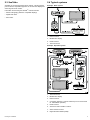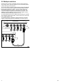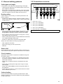
1
HS 5
Ins ta lla tion ins tructions
En g lis h
Da te : 08-2012
Docume nt numbe r: 87146-2-EN
© 2012 Ra yma rine UK Limite d
Trademark and patents notice
Autohelm, hsb2, RayTech Navigator, Sail Pilot, SeaTalk, SeaTalkNG, SeaTalkHS and Sportpilot are registered trademarks of Raymarine
UK Limited. RayTalk, Seahawk, Smartpilot, Pathfinder and Raymarine are registered trademarks of Raymarine Holdings Limited.
FLIR is a registered trademark of FLIR Systems, Inc. and/or its subsidiaries.
All other trademarks, trade names, or company names referenced herein are used for identification only and are the property of
their respective owners.
This product is protected by patents, design patents, patents pending, or design patents pending.
Fair Use Statement
You may print no more than three copies of this manual for your own use. You may not make any further copies or distribute or use the
manual in any other way including without limitation exploiting the manual commercially or giving or selling copies to third parties.
Product handbooks
The latest versions of all English and translated handbooks are available to download in PDF format from the website www.raymarine.com.
Please check the website to ensure you have the latest handbooks.
Copyright ©2012 Raymarine UK Ltd. All rights reserved.
ENGLISH
Document number: 87146-2
Date: 08-2012
Contents
Chapter 1 Introduction ............................................. 7
Handbook information ..................................................... 7
Product overview ............................................................ 7
Safety notices................................................................. 7
Important information ...................................................... 7
Chapter 2 Planning the installation ........................ 9
2.1 Installation checklist .................................................. 10
2.2 Parts supplied........................................................... 10
2.3 SeaTalkhs .................................................................. 11
2.4 Typical systems ........................................................ 11
2.5 Multiple switches....................................................... 12
Chapter 3 Cables and connections......................... 13
3.1 General cabling guidance .......................................... 14
3.2 Connections overview ............................................... 14
3.3 Network hardware ..................................................... 15
3.4 RayNet connector network cables .............................. 15
3.5 Network cable connector types .................................. 16
3.6 Equipment connection ............................................... 16
3.7 Power connection ..................................................... 17
Chapter 4 Installation ............................................... 19
4.1 Location requirements ............................................... 20
4.2 Mounting the unit ...................................................... 20
Chapter 5 Troubleshooting and support ................ 21
5.1 LED locations ........................................................... 22
5.2 LED indications......................................................... 23
5.3 Network switch troubleshooting.................................. 24
5.4 Raymarine customer support ..................................... 25
Appendix A Technical specification ....................... 27
5
6
HS5
Chapter 1: Introduction
Caution: Service and maintenance
Handbook information
This product contains no user serviceable
components. Please refer all maintenance and repair
to authorized Raymarine dealers. Unauthorized repair
may affect your warranty.
This handbook describes how to install the Raymarine HS5 network
switch as part of a marine electronics installation.
This handbook includes information to help you:
Water ingress
• plan your installation;
Water ingress disclaimer
• install and connect the product as a part of your system of
Raymarine electronics;
Although the waterproof rating capacity of this product meets the
IPX6 standard, water intrusion and subsequent equipment failure
may occur if the product is subjected to commercial high-pressure
washing. Raymarine will not warrant products subjected to
high-pressure washing.
• conduct checks to ensure that the product has been installed
correctly;
• obtain support if required.
This and other Raymarine product documentation is available to
download in PDF format from www.raymarine.com.
Product overview
A Raymarine network switch enables you to connect multiple
SeaTalkhs devices to a Raymarine multifunction display.
IMO and SOLAS
The equipment described within this document is intended for use
on leisure marine boats and workboats not covered by International
Maritime Organization (IMO) and Safety of Life at Sea (SOLAS)
Carriage Regulations.
Product disposal
Dispose of this product in accordance with the WEEE Directive.
Raymarine networks typically consist of at least 2 of the following
SeaTalkhs devices:
• Radar scanner.
• Digital Sounder Module (DSM).
• Thermal camera.
• Additional multifunction display.
The Waste Electrical and Electronic Equipment (WEEE)
Directive requires the recycling of waste electrical and electronic
equipment. Whilst the WEEE Directive does not apply to some
Raymarine products, we support its policy and ask you to be aware
of how to dispose of this product.
Technical accuracy
Safety notices
This product must be installed and operated in
accordance with the instructions provided. Failure to
do so could result in personal injury, damage to your
vessel and/or poor product performance.
To the best of our knowledge, the information in this document
was correct at the time it was produced. However, Raymarine
cannot accept liability for any inaccuracies or omissions it may
contain. In addition, our policy of continuous product improvement
may change specifications without notice. As a result, Raymarine
cannot accept liability for any differences between the product
and this document. Please check the Raymarine website
(www.raymarine.com) to ensure you have the most up-to-date
version(s) of the documentation for your product.
Warning: Switch off power supply
EMC installation guidelines
Ensure the vessel’s power supply is switched OFF
before starting to install this product. Do NOT connect
or disconnect equipment with the power switched on,
unless instructed in this document.
Raymarine equipment and accessories conform to the appropriate
Electromagnetic Compatibility (EMC) regulations, to minimize
electromagnetic interference between equipment and minimize the
effect such interference could have on the performance of your
system
Warning: Potential ignition source
Correct installation is required to ensure that EMC performance is
not compromised.
Warning: Product installation and
operation
This product is NOT approved for use in
hazardous/flammable atmospheres. Do NOT install in
a hazardous/flammable atmosphere (such as in an
engine room or near fuel tanks).
Warning: Product grounding
Before applying power to this product, ensure it has
been correctly grounded, in accordance with the
instructions in this guide.
Important information
Caution: Power supply protection
When installing this product ensure the power source
is adequately protected by means of a suitably-rated
fuse or automatic circuit breaker.
Introduction
For optimum EMC performance we recommend that wherever
possible:
• Raymarine equipment and cables connected to it are:
– At least 1 m (3 ft) from any equipment transmitting or cables
carrying radio signals e.g. VHF radios, cables and antennas.
In the case of SSB radios, the distance should be increased
to 7 ft (2 m).
– More than 2 m (7 ft) from the path of a radar beam. A radar
beam can normally be assumed to spread 20 degrees above
and below the radiating element.
• The product is supplied from a separate battery from that used
for engine start. This is important to prevent erratic behavior
and data loss which can occur if the engine start does not have
a separate battery.
• Raymarine specified cables are used.
• Cables are not cut or extended, unless doing so is detailed in
the installation manual.
7
Note: Where constraints on the installation prevent any of
the above recommendations, always ensure the maximum
possible separation between different items of electrical
equipment, to provide the best conditions for EMC performance
throughout the installation
Suppression ferrites
Raymarine cables may be fitted with suppression ferrites. These
are important for correct EMC performance. If a ferrite has to be
removed for any purpose (e.g. installation or maintenance), it must
be replaced in the original position before the product is used.
Use only ferrites of the correct type, supplied by Raymarine
authorized dealers.
Connections to other equipment
Requirement for ferrites on non-Raymarine cables
If your Raymarine equipment is to be connected to other equipment
using a cable not supplied by Raymarine, a suppression ferrite
MUST always be attached to the cable near the Raymarine unit.
Declaration of conformity
Raymarine UK Ltd. declares that this product is compliant with the
essential requirements of EMC directive 2004/108/EC.
The original Declaration of Conformity certificate may be viewed on
the relevant product page at www.raymarine.com.
Warranty registration
To register your Raymarine product ownership, please visit
www.raymarine.com and register online.
It is important that you register your product to receive full warranty
benefits. Your unit package includes a bar code label indicating the
serial number of the unit. You will need this serial number when
registering your product online. You should retain the label for future
reference.
8
HS5
Chapter 2: Planning the installation
Chapter contents
•
2.1 Installation checklist on page 10
•
2.2 Parts supplied on page 10
•
2.3 SeaTalkhs on page 11
•
2.4 Typical systems on page 11
•
2.5 Multiple switches on page 12
Planning the installation
9
2.1 Installation checklist
2.2 Parts supplied
Installation includes the following activities:
Installation Task
1
Plan your system.
2
Obtain all required equipment and tools.
3
Site all equipment.
4
Route all cables.
5
Drill cable and mounting holes.
6
Make all connections into equipment.
7
Secure all equipment in place.
8
Power on and test the system.
1
2
3
4
D12312-1
Schematic diagram
1. Network switch.
A schematic diagram is an essential part of planning any installation.
It is also useful for any future additions or maintenance of the
system. The diagram should include:
2. Fixing screws.
• Location of all components.
4. Documentation pack, consisting of:
• Connectors, cable types, routes and lengths.
3. Power cable (red and black).
• Installation instructions.
• Mounting template.
• Warranty policy.
10
HS5
2.3 SeaTalkhs
2.4 Typical systems
SeaTalkhs is an ethernet based marine network. This high speed
protocol allows compatible equipment to communicate rapidly and
share large amounts of data.
Example: Basic system
1
2
Information shared using the SeaTalkhs network includes:
• Shared cartography (between compatible displays).
• Digital radar data.
• Sonar data.
4
SeaTalkhs / RayNet
3
SeaTalkhs / RayNet
D12321-2
1. Network switch.
2. Multifunction display.
3. Radar scanner.
4. Thermal camera.
Example: Expanded system
3
3
SeaTalkhs / RayNet
7
8
4
SeaTalkhs / RayNet
6
2
SeaTalkhs / RayNet
2
5
1
D12582-1
1. Thermal camera.
2. Multifunction display.
3. Network switch.
4. Connection between 2 network switches (Port 5 must be used
for 1000 Mbit/S operation).
5. Radar scanner.
6. Antenna for Sirius weather receiver.
7. Sirius weather receiver.
8. Digital Sounder Module (DSM).
Planning the installation
11
2.5 Multiple switches
Systems with more than 5 SeaTalkhs devices require more than
one network switch. Network switches can be connected together
(“daisy-chaining”) for this purpose.
The network switch provides a dedicated high-speed (1000 Mbit/S)
port for connecting switches together while still retaining full data
bandwidth throughout the system. However, each switch only
has one high-speed port (port 5), so you can only connect up to
2 switches using the high-speed (1000 Mbit/S) connection. Any
additional network switches must be connected together using a
standard speed (100 Mbit/S) port (ports 1 to 4).
You should take this factor into account when planning your system.
The maximum number of SeaTalkhs devices that can be connected
in any single system is 25.
The following diagram illustrates 2 network switches connected
together using the high-speed (1000 Mbit/S) connection (port 5):
D12322-1
12
HS5
Chapter 3: Cables and connections
Chapter contents
•
3.1 General cabling guidance on page 14
•
3.2 Connections overview on page 14
•
3.3 Network hardware on page 15
•
3.4 RayNet connector network cables on page 15
•
3.5 Network cable connector types on page 16
•
3.6 Equipment connection on page 16
•
3.7 Power connection on page 17
Cables and connections
13
3.1 General cabling guidance
3.2 Connections overview
Cable types and length
It is important to use cables of the appropriate type and length
• Unless otherwise stated use only standard cables of the correct
type, supplied by Raymarine.
• Ensure that any non-Raymarine cables are of the correct quality
and gauge. For example, longer power cable runs may require
larger wire gauges to minimize voltage drop along the run.
Routing cables
Cables must be routed correctly, to maximize performance and
prolong cable life.
• Do NOT bend cables excessively. Wherever possible, ensure a
minimum bend diameter of 200 mm (8 in) / minimum bend radius
of 100 mm (4 in).
1
2
3
4
5
6
D12313-1
1. Power (12 V / 24 V).
2. Port 1 (10 or 100 Mbit/S).
200 mm (8 in)
3. Port 2 (10 or 100 Mbit/S).
4. Port 3 (10 or 100 Mbit/S).
100 mm (4 in)
5. Port 4 (10 or 100 Mbit/S).
6. Port 5 (10, 100, or 1000 Mbit/S).
• Protect all cables from physical damage and exposure to heat.
Use trunking or conduit where possible. Do NOT run cables
through bilges or doorways, or close to moving or hot objects.
Note: The protective caps should be fitted to any unused ports.
• Secure cables in place using tie-wraps or lacing twine. Coil any
extra cable and tie it out of the way.
• Where a cable passes through an exposed bulkhead or deckhead,
use a suitable watertight feed-through.
• Do NOT run cables near to engines or fluorescent lights.
Always route data cables as far away as possible from:
• other equipment and cables,
• high current carrying ac and dc power lines,
• antennae.
Strain relief
Ensure adequate strain relief is provided. Protect connectors from
strain and ensure they will not pull out under extreme sea conditions.
Circuit isolation
Appropriate circuit isolation is required for installations using both
AC and DC current:
• Always use isolating transformers or a separate power-inverter
to run PC’s, processors, displays and other sensitive electronic
instruments or devices.
• Always use an isolating transformer with Weather FAX audio
cables.
• Always use an isolated power supply when using a 3rd party
audio amplifier.
• Always use an RS232/NMEA converter with optical isolation on
the signal lines.
• Always make sure that PC’s or other sensitive electronic devices
have a dedicated power circuit.
Cable shielding
Ensure that all data cables are properly shielded that the cable
shielding is intact (e.g. hasn’t been scraped off by being squeezed
through a tight area).
14
HS5
3.3 Network hardware
3.4 RayNet connector network cables
Item
Part number
Notes
Cable
Part number
HS5 SeaTalkhs network
switch
A80007
5–port switch for
network connection
of multiple SeaTalkhs
devices featuring
RayNet connectors.
Equipment with
SeaTalkhs connectors
can also be connected
via suitable adaptor
cables.
1 m (3.28 ft) RayNet to SeaTalkhs
(RJ45) cable
A62360
2 m (6.56 ft) RayNet to RayNet cable
A62361
5 m (16.4 ft) RayNet to RayNet cable
A80005
10 m (32.8 ft) RayNet to RayNet cable
A62362
20 m (65.6 ft) RayNet to RayNet cable
A80006
RayNet cable puller 5 pack
R70014
SeaTalkhs
network
E55058
8–port switch for network
connection of multiple
SeaTalkhs devices.
E55060
Enables direct
connection of SeaTalkhs
devices to smaller
systems where a switch
is not required. Also
enables the connection
of SeaTalkhs devices
to an HS5 SeaTalkhs
network switch (in
conjunction with a
RayNet to RJ45 cable).
switch
SeaTalkhs crossover
coupler
Cables and connections
15
3.5 Network cable connector types
3.6 Equipment connection
There are 2 types of network cable connector — SeaTalkhs and
RayNet.
SeaTalkhs equipment is connected to the switch using RayNet
cables or a combination of SeaTalkhs cable, SeaTalkhs crossover
coupler, and RayNet to RJ45 cable.
SeaTalkhs connector.
RayNet connector.
There are 2 typical scenarios when connecting SeaTalkhs equipment
to the network switch:
Required cabling for
new network switch
Scenario
Existing cabling
1. Existing or new
installation with
Raymarine equipment
that has a RayNet
connector.
RayNet or none.
• RayNet to RayNet
cable.
2. Existing installation
with Raymarine
equipment that has
a SeaTalkhs connector.
SeaTalkhs cables.
• Existing SeaTalkhs
cables.
• SeaTalkhs crossover
coupler.
• RayNet to RJ45
cable.
These scenarios are illustrated below:
Connection scenario 1 — equipment with RayNet connector
1
2
3
D12326-1
1. SeaTalkhs equipment with RayNet connector.
2. RayNet to RayNet cable.
3. Network switch.
16
HS5
Connection scenario 2 — equipment with SeaTalkhs connector
3.7 Power connection
The power for the network switch is provided directly by a 12 V or
24 V power source.
The network switch is supplied with a power cable with bare stripped
wires, suitable for direct connection to a 12 V or 24 V power supply:
1
2
1
2
3
3
4
4
5
D12314-1
1. Network switch.
2. Power cable, red and black (supplied).
5
3. Red cable (positive).
D12324-1
1. SeaTalkhs equipment — for example, E-Series Widescreen
display.
2. SeaTalkhs cable.
3. SeaTalkhs crossover coupler.
4. Network switch.
5. RayNet to RJ45 cable.
4. Screen wire.
5. Black cable (negative).
Warning: Do NOT power this product
from a SeaTalkng backbone
To avoid possible damage to equipment, do NOT use
a SeaTalkng backbone as the power source for this
product.
Warning: Do NOT connect a SeaTalkng
backbone to a 24 V power supply.
To avoid possible damage to equipment, do NOT
use the supplied power cable to connect a SeaTalkng
backbone to a 24 V power supply.
Cables and connections
17
18
HS5
Chapter 4: Installation
Chapter contents
•
4.1 Location requirements on page 20
•
4.2 Mounting the unit on page 20
Installation
19
4.1 Location requirements
4.2 Mounting the unit
When selecting a location for the unit it is important to consider a
number of factors.
Before mounting the unit, ensure that you have:
• Do NOT install near sources of heat or vibration (for example,
an engine).
• Selected a suitable location with cable clearance below the unit.
• Identified the cable connections and routing.
• Install below decks in a dry area.
1
2
3
D12317-1
• Must be mounted on a vertical surface. Sides and top must be
level.
1. Fix the supplied mounting template to the selected location,
using masking or self-adhesive tape.
2. Drill 2 holes at the positions indicated on the template.
3. Position the unit and hold it in place.
4. Insert a supplied mounting screw into each of the mounting
holes. Do NOT tighten at this stage.
5. Gently push the unit downwards until both screws lock into
position in the top of the mounting holes.
6. Tighten the screws.
20
HS5
Chapter 5: Troubleshooting and support
Chapter contents
•
5.1 LED locations on page 22
•
5.2 LED indications on page 23
•
5.3 Network switch troubleshooting on page 24
•
5.4 Raymarine customer support on page 25
Troubleshooting and support
21
5.1 LED locations
LEDs indicating the status of the switch are located across the top
of the unit.
1
2
D12327-1
Item
Description
1
Power status.
2
Port status (one LED
corresponding to each port).
22
LED color
(Red)
(Green)
HS5
5.2 LED indications
The LEDs on the unit indicate status information for diagnostic purposes.
Power LED
LED activity (based on 1000 ms
(1 second) cycle)
LED state description
Unit status description
Off
Red
1000 ms
0 ms
Off
No power.
0 ms
1000 ms
Continuous red.
Unit powered on.
Port LED
LED activity (based on 1000 ms
(1 second) cycle)
LED state description
Unit status description
Off
Green
1000 ms
0 ms
Off
No network connection.
0 ms
1000 ms
Continuous green.
Network connection established, but no network activity detected.
500 ms
500 ms
Blinking green.
Network connection established; network activity detected.
0 ms
84 ms
Blinking green (fast).
Network connection established; 1000 Mbit/S network activity
detected.
0 ms
170 ms
Blinking green (medium).
Network connection established; 100 Mbit/S network activity
detected.
0 ms
340 ms
Blinking green (slow).
Network connection established; 10 Mbit/S network activity
detected.
Troubleshooting and support
23
5.3 Network switch troubleshooting
Problems with the network switch and possible causes and solutions are described here.
Problem
Possible causes
Possible solutions
No LEDs lit.
No power.
Check power connection to unit.
Red power LED is lit but no port green
LEDs are lit.
Faulty or no connection for that port.
Check the cable connection for the port. Check any additional connections
(such as SeaTalkhs crossover couplers).
No network activity.
• Check that the unit connected to the switch is powered on.
• Check that unit connected to the switch is currently transferring data.
This can be confirmed by performing an action on the multifunction
display that will initiate data transfer for the relevant unit — for example,
if suspect a problem with the port corresponding to a connected radar
scanner, range in or out in the radar application to initiate data activity.
Slow or poor performance.
24
Large system featuring more than one
network switch. Network switches are
connected together via a 100 Mbit/S port.
Use the dedicated 1000 Mbit/S port (port 5) to connect network switches
together. You can connect a maximum of 2 switches together using a 1000
Mbit/S connection.
HS5
5.4 Raymarine customer support
Raymarine provides a comprehensive customer support service.
You can contact customer support through the Raymarine website,
telephone and email. If you are unable to resolve a problem, please
use any of these facilities to obtain additional help.
Web support
Please visit the customer support area of our website at:
www.raymarine.com
This contains Frequently Asked Questions, servicing information,
e-mail access to the Raymarine Technical Support Department and
details of worldwide Raymarine agents.
Telephone and email support
In the USA:
• Tel: +1 603 324 7900
• Toll Free: +1 800 539 5539
• Email: [email protected]
In the UK, Europe, the Middle East, or Far East:
• Tel: +44 (0)13 2924 6777
• Email: [email protected]
Product information
If you need to request service, please have the following information
to hand:
• Product name.
• Product identity.
• Serial number.
• Software application version.
You can obtain this product information using the menus within your
product.
Troubleshooting and support
25
26
HS5
Appendix A Technical specification
Nominal supply voltage
12 or 24 V dc
Operating voltage range
9 to 32 V dc
Power consumption (typical)
• < 2.5 W
• < 600 mA @ 12 V
Environmental
Installation environment
• Operating temperature: -25 ºC to
+55 ºC (-13 ºF to 131 ºF)
• Storage temperature: -25 ºC to
+70 ºC (-13 ºF to 158 ºF)
• Relative humidity: max 93%
• Waterproof to IPX6
Conformance
• Europe: 2004/108/EC
• Australia and New Zealand: C-Tick,
Compliance Level 2
• China: CCS certification
Supported connection protocols
• SeaTalkhs
Supported connection speeds
• 10 Mbit/S
• 100 Mbit/S
• 1000 Mbit/S (Port 5 only)
Technical specification
27
28
HS5
www.ra ym a rin e .c o m