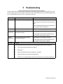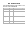
1
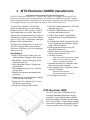
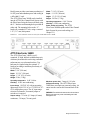
ATTO FibreCenter™ 3400R/D
Installation and Operation Manual
© 2002 ATTO Technology, Inc. All rights reserved. All brand or product names are trademarks of their respective
holders. No part of this manual may be reproduced in any form or by any means without the express written
permission of ATTO Technology, Inc.
07/02
1.0
Document Control Number: PRMA 0319-000
Contents
1 Fibre Channel is a key technology for storage ................................1
Glossary
2 ATTO FibreCenter 3400R/D characteristics .....................................3
Specifications
ATTO FibreCenter 3400R
ATTO FibreCenter 3400D
3 ATTO FibreCenter installation options .............................................5
Quick start instructions
ATTO Fibre Channel Rack System
FibreCenter 3400D
3.1 Setting up the Fibre Channel Rack System ........................7
Fibre Channel Rack System dimensions
Operating environment
Air flow and cooling
Internal power distribution
Installing a power module
Removing a power module
3.2 Installing the ATTO FibreCenter 3400R ..............................9
Fibre Channel Rack System
Removing the FibreCenter
Cabling Fibre Channel ports
Determining Telnet status
3.3 Installing the ATTO FibreCenter 3400D ..............................11
Removing the FibreCenter 11
Cabling Fibre Channel ports
Determining Telnet status
3.4 Configuring the ATTO FibreCenter .....................................13
Configuring ports
Data transfer when setting up zones
FibreCenter behavior on reset or power-up
Example: set up one zone
Example: set up multiple zones
Example: change parameters
4 Command Line Interface use and guidance .....................................15
CLI command conventions
4.1 General use commands ........................................................17
Commit Zone
Help
Quit
Reset
Switch Delay
Verbose
4.2 Ethernet and Telnet configuration commands ...................18
Default Router
Echo
Factory Defaults
Idle Timeout
IP Address
Security Traps
Subnet Mask
4.3 Configuration commands .....................................................19
Commit Zone
Reset
Switch Delay
Verify Zone
Zone Attributes
Zone Info
Zone Map
Zone Restore
Zone Speed
Zone Threshold
4.4 Diagnostic commands ..........................................................21
Status
Verify Zone
Version
Zone Info
5 Troubleshooting ..................................................................................22
6 Updating firmware ..............................................................................23
Index: Command Line Interface ................................................................ i
Appendix A: Standards and compliances ...........................................ii
Appendix B: Contact ATTO Technology, Inc. .....................................iii
1 Fibre Channel is a key technology for storage
Fibre Channel is a serial communications technology designed to transfer large amounts of data
between a variety of hardware systems over long distances. It is a key technology for applications that
require shared, high bandwidth access to storage.
Fibre Channel provides a logical point-to point
serial channel for the transfer of data between a
buffer at a source device and a buffer at a
destination device. It moves buffer contents from
one port to another, without regard to the format
or meaning of the data, so different upper level
protocols are able to run over Fibre Channel
hardware.
The Fibre Channel architecture is structured as a
hierarchical set of protocol layers. Defined within
these layers are rules for signal interfaces, serial
encoding and decoding, error control, frame
format and communications protocols.
A SAN is a shared storage architecture connecting
computers and storage devices for online data
access. Each connected system can directly access
any attached storage device. Storage devices
could include RAID, tape backup, tape library,
CD-ROM library or JBOD.
SANs maintain greater fault tolerance and load
balancing by supporting server clustering and
failover (the ability for one server to take over for
another in the event of a failure).
The ATTO FibreCenter™ 3400R/D hub
integrates industry-leading performance and
Storage Area Network capabilities into mid-range
applications.
Glossary
Some terms used in the Fibre Channel industry are defined below. More information is available through
the Fibre Channel Industry Association (www.fibrechannel.com), the Storage Area Networking Industry
Association (www.snia.org) and the Fibre Channel Consortium (www.iol.unh.edu).
Term
Definition
firmware
Software stored in read-only memory (ROM) or programmable ROM (PROM).
Firmware is often responsible for the behavior of a system when it is first turned
on.
FC-AL
Fibre Channel Arbitrated Loop: A Fibre Channel network in which up to 126
nodes are connected in a loop topology, with each transmitter connecting to the
receiver of the device to its logical right. The Fibre Channel Arbitrated Loop
protocol used for transmission is different from Fibre Channel point to point
protocols. Multiple FC-AL loops can be connected via a fabric switch to extend the
network.
FL-port
A port in the Fibre Channel fabric where an NL_port may attach in an arbitrated
loop.
hub
A device which provides a common connection to devices on a Fibre Channel
Arbitrated Loop
initiator device
A component which originates a command
1 ATTO FibreCenter 3400 Installation and Operation Manual
Term
Definition
LED
Light-emitting diode, a type of diode that emits light when current passes through
it. Visible LEDs are used as indicator lights on all sorts of electronic devices.
LUN
Logical Unit Number: a Fibre Channel identifier of a device
N_port
A port that connects a node to a fabric or to another node as in a point-to-point
configuration.
NL port
A port that connects a node in Fibre Channel arbitrated loop
POST
Power On Systems Test: a series of self-diagnostic tests stored in RAM which run
when power is first applied to a component.
switch
A device which controls routing of data from one component to another.
topology
Logical layout of the parts of a computer system or network and their
interconnections
warm boot
Startup without cycling the electric power. Operations include POST and
refreshing all configuration settings. All software in Flash memory will be reloaded
into RAM.
Managed Data Path Model 2
2 ATTO FibreCenter 3400R/D characteristics
The ATTO FibreCenter 3400R/D is a 2-Gigabit Fibre Channel hub configured with eight (8) Fibre
Channel ports and an ethernet management port. The FibreCenter 3400R/D is designed to integrate
industry leading performance and Storage Area Network (SAN) capabilities into mid-range applications
by providing a high-speed, central connection point for Fibre Channel connections.
The FibreCenter 3400R/D is a flexible hub
capable of distributing pairs of ports among 1
through 4 zones (to a total of 8 ports). Up to 48
zone configurations are possible. Zones allow
different devices to communicate more effectively
within the zone. Each zone may run at a different
speed (1 Gb or 2 Gb). Configuration is managed
through a 10BaseT Ethernet port.
The FibreCenter 3400R hub may be used in an
ATTO Fibre Channel Rack System while the
FibreCenter 3400D may be used on a desktop or
mounted in a rack.
Specifications
❈Eight 2-Gigabit Fibre Channel ports with
Small Formfactor Pluggable (SFP) interface
❈400 MB/sec. maximum throughput in full
duplex mode per zone
❈Auto negotiation between 2-Gigabit and 1Gigabit modes
❈Port management interface for “on-the-fly”
configuration
❈Ethernet configuration, management and
monitoring
❈Modular design for maximum data reliability,
availability and serviceability.
❈Support for Fibre Channel Class 2, Class 3
and Intermix specifications
❈ Support for full-duplex data transfers
❈ Full Fibre Channel support for FC-P2, PLDA
and public loop login
❈32 MB of SDRAM memory for code
execution and Ethernet packets.
❈4 MB of flash memory, field upgradable
through Ethernet, for code and parameter
storage.
❈Command Line Interface provides local and
remote management and diagnostic support
using Telnet over Ethernet
❈Field upgradeable firmware using FTP
through the Ethernet port
❈Digital retiming circuits eliminate jitter
transfer to downstream devices.
❈ Lockable port status
Offline = Port is disconnected from FC network.
Online = Port is connected to FC network
subject to automatic bypass criteria.
❈Automatic bypass may be disabled to allow
link to always remain connected.
❈ Link transmitter may be optionally disabled
when port is disabled.
Reduced power consumption.
No external monitoring of FC activity.
❈ All settings are persistent.
ATTO FibreCenter 3400R
The ATTO FibreCenter 3400R hub provides
maximum dependable performance for high
availability systems through a hot-swappable,
dual power module when housed in one module
bay of a dual module, 1U high, industry standard
rack enclosure complete with mounting brackets.
Using two modules in the ATTO Fibre Channel
3 ATTO FibreCenter 3400 Installation and Operation Manual
Rack System provides a maximum port density of
16 SFP ports and redundant power and cooling in
a full width 1U rack.
The ATTO FibreCenter 3400R can be installed
into the ATTO Fibre Channel Rack System with
the FibreCenter facing the front or the back using
the “L”-brackets and mounting holes provided on
either end. The mounting holes on the “L”bracket fit a standard 19” rack, using a centered
1.25” (31.7 mm) hole pattern.
Exhibit 2-1
7 9/16" (193 mm)
Depth: 9 11/16" (246 mm)
Height: 1 3/4” (1U) (43 mm)
Weight: 2.85 lbs (1.3 Kg)
Operating temperature: 0-40° Celsius
Humidity: 0-90% non-condensing
Power, airflow and cooling The ATTO
FibreCenter 3400R depends on the Fibre Channel
Rack System for power and cooling (see
Chapter 3.1)
Width:
Fibre Channel connector side of the ATTO FibreCenter 3400R
ATTO FibreCenter 3400D
The ATTO FibreCenter 3400D is a selfcontained, 1U high, half rack width desktop unit
which may be mounted in a rack using a standard
rackmount tray or rack mount brackets. Two
hubs may be coupled using the optional “L”
brackets providing a maximum port density of
16 SFP ports.
Width: 8 1/4" (210 mm)
Depth: 9 11/16" (246 mm)
Height: 1 3/4” (1U) (43 mm)
Weight: 2 lbs (.91 Kg)
Operating temperature: 0-40° Celsius
Humidity: 0-90% non-condensing
Input voltage 110/230V AC with an operating
input range of 90-132V AC or 175-264V AC, 4763 Hz single phase power. The AC input range
selection is automatic. No manual jumper or
switchover is required.
Output voltage +12 volts @ 5 Amps (60 watts)
continuous, 5.8 Amps (70 watts) peak.
2 amps @ 110 volts
Airflow and cooling The ATTO FibreCenter
3400D does not require any external cooling. Air
enters into the vents on the front and back of the
unit.
Maximum power draw
WARNING Do not block the vents on the main enclosure.
Blocking the vents may cause overheating and could
damage the unit.
Managed Data Path Model 4
3 ATTO FibreCenter installation options
The ATTO FibreCenter 3400R/D provides a 2-gigabit Fibre Channel rackmount or desktop hub with
eight Fibre Channel ports configured via an Ethernet port.
The ATTO FibreCenter 3400R/D hub integrates
industry-leading performance and Storage Area
Network capabilities into mid-range applications.
Available for integration into the ATTO Fibre
Channel Rack System as a rackmount module or
as a stand alone desktop module which also can be
mounted in a rack, the ATTO FibreCenter
3400R/D hub provides dependable performance
for high availability systems.
Quick start instructions
The ATTO FibreCenter 3400R/D offers a variety
of ways to connect into a SAN. The following is a
quick start description.
To integrate the FibreCenter 3400R into the
ATTO Fibre Channel Rack System
1
Slide the hub module horizontally into the
rack enclosure until you feel it make contact
with the backplane connector.
2
Secure the hub module by tightening the
two thumbscrews (hand tight).
3
Apply power to the rack enclosure. The
FibreCenter 3400R will be active
approximately 40 seconds after power is
applied.
4
Connect to the management port via a
standard RJ45 Ethernet cable.
5
Connect Fibre Channel devices to the ATTO
FibreCenter using SFPs and standard
cables manufactured for Fibre Channel use.
6
Connect a host computer to the
FibreCenter. The default IP address of the
hub is 192.168.1.1. You can use a crossover
Ethernet cable to direct connect a PC to the
FibreCenter 3400R or a standard Ethernet
cable to attach to a network device.
7
Change the IP address of the host computer
to 192.168.1.X (where X does not equal 1).
8
Launch a Hyperterminal session.
9
From the menu bar at the top, select File New Connection
10 Enter a name for the connection.
11 Select TCP/IP as the connection method.
5 ATTO FibreCenter 3400 Installation and Operation Manual
12 Enter the IP address of the FibreCenter
(default is 192.168.1.1)
13 Enter zonedhub (the factory default login)
when prompted for the login.
14 Enter zonedhub (the factory default
password) when prompted for the
password. (Make sure local echo is off
before entering a secure password).
15 A > prompt will be displayed if the user
name and password were entered
successfully. You should now be connected.
Type help for a list of commands. Enter the
CLI commands required to set up your
system if different from previously set
configurations. (See Chapter 3.4)
To set up the FibreCenter 3400D
1
Set the FibreCenter 3400D where you want
it, either on a flat surface or mounted inside
a rack using brackets and the mounting
holes on the hub’s case.
2
Insert the power cable into the power
connector.
3
Apply power. The FibreCenter 3400D will be
active approximately 40 seconds after
power is applied.
4
Connect to the management port via a
standard RJ45 Ethernet cable.
5
Connect Fibre Channel devices to the ATTO
FibreCenter using SFPs and standard
cables manufactured for Fibre Channel use.
6
Connect a host computer to the
FibreCenter. The default IP address of the
hub is 192.168.1.1. You can use a crossover
Ethernet cable to direct connect a PC to the
FibreCenter 3400D or a standard Ethernet
cable to attach to a network device.
7
Change the IP address of the host computer
to 192.168.1.X (where X does not equal 1).
8
Launch a Hyperterminal session.
9
From the menu bar at the top, select File New Connection
10 Enter a name for the connection.
11 Select TCP/IP as the connection method.
12 Enter the IP address of the FibreCenter
(default is 192.168.1.1)
13 Enter zonedhub (the factory default login)
when prompted for the login.
14 Enter zonedhub (the factory default
password) when prompted for the
password. (Make sure local echo is off
before entering a secure password).
15 A > prompt will be displayed if the user
name and password were entered
successfully. You should now be connected.
Type help for a list of commands. Enter the
CLI commands required to set up your
system if different from previously set
configurations. (See Chapter 3.4)
Managed Data Path Model 6
3.1 Setting up the Fibre Channel Rack System
The ATTO Fibre Channel Rack System is a configurable 19” rack system with two bays to house the
ATTO FibreCenter 3400R and two bays to house power modules. The 1U rackmount enclosure provides
the flexibility to integrate the ATTO FibreCenter 3400R in pairs.
The following items are included with the ATTO
Fibre Channel Rack System:
❈Up to two (2) ATTO FibreCenter 3400R
modules
❈One (1) or two (2) power modules containing
independent cooling fans
❈One (1) or two (2) AC shielded power
cord(s).
❈Two (2) rackmount “L” brackets and (4)
screws for mounting the unit into the rack.
❈Installation and Operation Manual
The main enclosure of the ATTO Fibre Channel
Rack System houses the FibreCenter 3400R
modules and power modules: two bays for
FibreCenter 3400R and two bays for power
modules.
The ATTO FibreCenter 3400R can be installed
into the ATTO Fibre Channel Rack System with
the FibreCenter facing the front or the back using
the “L”-brackets and mounting holes provided on
either end. The mounting holes on the “L”bracket fit a standard 19” rack, using a centered
1.25” (31.7 mm) hole pattern.
The power modules will slide into the ATTO
Fibre Channel Rack System enclosure in either of
the two bays on the end of the rack enclosure that
is closer to the backplane and farthest away from
the cooling vents in the sides of the rack
enclosure.
Fibre Channel Rack System dimensions
Width: 17.4" (441.6 mm)
Depth: 17" (431.5 mm)
Height: 1.72" (43.7 mm)
Operating environment
Operating temperature: 0-40° Celsius
Humidity: 0-90% non-condensing
7 ATTO FibreCenter 3400 Installation and Operation Manual
Air flow and cooling
The Fibre Channel Rack System cooling fans are
contained within the power modules. Each power
module contains two 8-CFM fans and provides a
total of 16 CFM of airflow. A system that has two
power modules installed will have a total of 32
CFM of airflow. Air enters through the sides of
the enclosure and is exhausted out the power
modules. Ambient air near the inlets should not
exceed 40° C.
WARNING Do not block the vents on either side of the
main enclosure. Blocking the vents may cause
overheating and could damage the product.
Internal power distribution
The ATTO Fibre Channel Rack System provides
a redundant power scheme with two hot
swappable power supply modules. Each power
supply module feeds 12V to the backplane. Power
is distributed to the FibreCenter 3400R and the
fans from the backplane.
A failure of one power supply will not affect the
functionality of the FibreCenter 3400R or the
cooling system since the second supply would
continue to supply power to the backplane. If you
have two power supplies in the ATTO Fibre
Channel Rack System, one supply can be
removed and replaced without affecting the rest of
the system in any way.
The FibreCenter 3400R detects power supply
failures, voltage regulation and failover.
NOTE: Power modules will load balance
when there are two present in the ATTO Fibre
Channel Rack System
Input voltage: 110/230V AC, with an operating
input range of 90-132V AC or 175-264V AC, 4763Hz, single phase. The AC input range selection
is automatic. No manual jumper or switchover is
required.
Output voltage: +12 Volts @ 5 Amps (60 watts)
continuous, 5.8 amps (70 watts) peak.
Power draw: The maximum power draw is 2
Amps @ 110 Volts for the entire ATTO Fibre
Channel Rack System. The ATTO Fibre Channel
Rack System with two power modules draws only
2 Amps @ 110 Volts.
LED indicator The green LED indicator on the
power module will light when the module is
correctly installed, the switch is turned on, power
is being drawn from this module and that power is
available on the backplane. The LED will not be
illuminated if the power module is not turned on.
Do not plug the AC power cord in and turn on the
power switch if the power module is not installed.
IEC Power Receptacle and Switch One standard
IEC320 power receptacle and switch provides
easy adaptability to different voltage standards
throughout the world.
Exhibit 3.1-1
Rack System power module
Exhibit 3.1-2
Cooling airflow patterns
Installing a power module
1
Make sure the power switch on the rear of
the power module is in the off position and
the power cord is disconnected.
2
Slide the power module into the rack
enclosure until you feel it make contact with
the backplane connector. The face of the
power module should be flush against the
rack enclosure edges.
3
Secure the power module by tightening the
two thumb screws (hand tight).
4
Connect the AC power cord to the power
module and plug it into an appropriate
receptacle.
5
Turn the power switch on the power module
to the on position. Verify that the green LED
is illuminated.
Removing a power module
1
The power switch on the rear of the power
module must be in the off position. Make
sure the power LED is NOT illuminated.
2
Disconnect the power cord from the power
module as well as the AC power source.
3
Loosen the two thumb screws on the face of
the power module.
4
Carefully slide the power module out of the
rack enclosure.
Managed Data Path Model 8
3.2 Installing the ATTO FibreCenter 3400R
The ATTO FibreCenter 3400R fits into a standard rack mount module enclosure such as the ATTO
FibreChannel Rack System. While configuration changes can be made “on the fly,” data transmission
will be interrupted. To make changes without impacting data, make changes before activating the data
transmission.
To install the ATTO FibreCenter 3400R into
the ATTO Fibre Channel Rack System:
6
Connect a host computer to the
FibreCenter.
1
Slide the hub module horizontally into the
rack enclosure until you feel it make contact
with the backplane connector. The face of
the hub module should be flush against the
rack enclosure’s edge.
•Use a standard Ethernet cable when
connecting to a network device. The IP
address of the network must be different
from the default FibreCenter 3400R/D
address, 192.168.1.1
2
Secure the hub module by tightening the
two thumbscrews (hand tight).
•Use a crossover Ethernet cable if you are
making a direct connect to the FibreCenter.
3
Apply power to the rack enclosure.
•The ATTO FibreCenter takes about 40
seconds to begin operation after power-up
or execution of the Reset command. All
ports are disabled during this 40 seconds.
•When the FibreCenter begins operation, it
will use its default configuration or the last
mapping designated by the Set Zone and
Commit Zone commands.
•The power LEDs will illuminate
immediately.
•All FibreCenter port LEDs will blink one at
a time, from left to right, then all will blink
twice to indicate they are functional.
•The FibreCenter is now active.
4
Connect to the management port via a
standard RJ45 Ethernet cable. It may take
up to 40 seconds for the hub to initiate the
Ethernet connection.
5
Connect Fibre Channel devices to the ATTO
FibreCenter using SFPs and standard
cables manufactured for Fibre Channel use.
7
Change the IP address of the host computer
to 192.168.1.X (where X does not equal 1).
8
Launch Hyperterminal.
9
From the menu bar at the top, select File New Connection
10 Enter a name for the connection.
11 Select TCP/IP as the connection method.
12 Enter the IP address of the FibreCenter
(default is 192.168.1.1)
13 Enter zonedhub (the factory default login))
when prompted for the login.
14 Enter zonedhub (the factory default
password) when prompted for the
password. (Make sure local echo is off
before entering a secure password).
15 You should now be connected. Type help for
a list of commands. Enter the CLI
commands required to set up your system if
different from previously set configurations
or defaults.
Removing the FibreCenter
•Be aware of the cable limitations as listed
in the chart on the next page.
1
Disconnect all cables from the face of the
hub module.
•The Online LED illuminates for each port
with a connected cable if the connected
device is powered up and online.
2
Loosen the two thumbscrews on the face of
the hub module.
3
Carefully slide the hub module out of the
rack
9 ATTO FibreCenter 3400 Installation and Operation Manual
Cabling Fibre Channel ports
The FibreCenter 3400R uses a Small Formfactor
Pluggable (SFP) Fibre Channel interface. The
type of cable to use varies depending upon the
application, environment and distance. The
Cable length
following table illustrates the different cable
options available.
Make sure all cables are anchored securely at both
ends with the proper connectors.
Cable type
Cable size
Connector
up to 175 meters
multimode fiber optic
62.5 micron
LC
up to 500 meters
multimode fiber optic
50 micron
LC
up to 13 meters*
unequalized copper
HSSDC-2
*The maximum length may be shorter with 2-Gb transmission.
Determining Telnet status
Various parameters can be changed using Telnet.
While configuration changes can be made “on the
fly,” data transmission will be interrupted. To
make changes without impacting data, make
changes before activating data transmission.
While connected to a remote host, telnet
command mode may be entered by typing the
telnet escape character, ``^]'' and the normal
terminal editing conventions are available. The
escape character will return to the command mode
of the telnet which began controlling the terminal.
Use the send escape command to switch to
Exhibit 3.2-1
command mode in later telnet sessions on remote
hosts.
Telnet commands Type only enough of each
command and the arguments to identify them.
Send arguments
Send one or more special character sequences to
the remote host. The following arguments may be
specified (more than one argument may be
specified at a time):
get status
If the remote side supports the telnet status
command, get status will request the server to
send its current option status.
A typical command/response sequence during a Telnet session.
Telnet session screen
Explanation
set zone map 1:all
Prepares to map all ports to zone 1 with default parameters.
OK
$
Commit Zone
Valid input, accepted
Telnet prompt: ready for next command.
Type the next command immediately after the prompt ($ Commit Zone)
Implements changes to the hardware configuration,
Connection complete
Telnet prompt: ready for next command
OK
$
Managed Data Path Model 10
3.3 Installing the ATTO FibreCenter 3400D
The ATTO FibreCenter 3400D is a stand alone desktop model which may be mounted into a standard
rack. While configuration changes can be made “on the fly,” data transmission will be interrupted. To
make changes without impacting data, make changes before activating the data transmission.
•Be aware of the cable limitations as listed
in the chart on the next page.
To install the ATTO FibreCenter 3400D
1
Set the FibreCenter 3400D where you want
it, either on a flat surface or mounted inside
a rack using brackets and the mounting
holes on the hub’s case.
2
Insert the power cable into the power
connector.
3
Apply power. The FibreCenter 3400D will be
active approximately 40 seconds after
power is applied.
•The Online LED illuminates for each port
with a connected cable if the connected
device is powered up and online.
6
Connect a host computer to the
FibreCenter. The default IP address of the
hub is 192.168.1.1. If your network is
running under 192.168.1.X, a standard
network cable is appropriate. To direct
connect to the FibreCenter, you will need to
use a crossover Ethernet cable.
7
Change the IP address of the host computer
to 192.168.1.X (where X does not equal 1).
•When the FibreCenter begins operation, it
will use its default configuration or the last
mapping designated by the Set Zone and
Commit Zone commands.
8
Launch Hyperterminal.
9
From the menu bar at the top, select File New Connection
•The power LEDs will illuminate
immediately.
11 Select TCP/IP as the connection method.
•The ATTO FibreCenter takes about 40
seconds to begin operation after power-up
or execution of the Reset command. All
ports are disabled during this 40 seconds.
•All FibreCenter port LEDs will blink one at
a time, from left to right, then all will blink
twice to indicate they are functional.
•The FibreCenter is now active.
4
Connect to the management port via a
standard RJ45 Ethernet cable. It may take
up to 40 seconds for the hub to initiate the
Ethernet connection.
5
Connect Fibre Channel devices to the ATTO
FibreCenter using SFPs and standard
cables manufactured for Fibre Channel use.
11 ATTO FibreCenter 3400 Installation and Operation Manual
10 Enter a name for the connection.
12 Enter the IP address of the FibreCenter
(default is 192.168.1.1)
13 Enter zonedhub (the factory default login))
when prompted for the login.
14 Enter zonedhub (the factory default
password) when prompted for the
password. (Make sure local echo is off
before entering a secure password).
15 You should now be connected. Type help for
a list of commands. Enter the CLI
commands required to set up your system if
different from previously set configurations
or defaults.
Cabling Fibre Channel ports
The FibreCenter 3400D uses a Small Formfactor
Pluggable (SFP) Fibre Channel interface. The
type of cable to use varies depending upon the
application, environment and distance. The
Cable length
following table illustrates the different cable
options available.
Make sure all cables are anchored securely at both
ends with the proper connectors.
Cable type
Cable size
Connector
up to 175 meters
multimode fiber optic
62.5 micron
LC
up to 500 meters
multimode fiber optic
50 micron
LC
up to 13 meters*
unequalized copper
HSSDC-2
*The maximum length may be shorter with 2-Gb transmission.
Determining Telnet status
Various parameters can be changed using Telnet.
While configuration changes can be made “on the
fly,” data transmission will be interrupted. To
make changes without impacting data, make
changes before activating data transmission.
While connected to a remote host, telnet
command mode may be entered by typing the
telnet escape character, ``^]'' and the normal
terminal editing conventions are available. The
escape character will return to the command mode
of the telnet which began controlling the terminal.
Use the send escape command to switch to
Exhibit 3.3-1
command mode in later telnet sessions on remote
hosts.
Telnet commands Type only enough of each
command and the arguments to identify them.
Send arguments
Send one or more special character sequences to
the remote host. The following arguments may be
specified (more than one argument may be
specified at a time):
get status
If the remote side supports the telnet status
command, get status will request the server to
send its current option status.
A typical command/response sequence during a Telnet session.
Telnet session screen
Explanation
set zone map 1:all
Prepares to map all ports to zone 1 with default parameters.
OK
$
Commit Zone
Valid input, accepted
Telnet prompt: ready for next command.
Type the next command immediately after the prompt ($ Commit Zone)
Implements changes to the hardware configuration,
Connection complete
Telnet prompt: ready for next command
OK
$
Managed Data Path Model 12
3.4 Configuring the ATTO FibreCenter
The ATTO FibreCenter 3400R/D may be configured into 48 combinations of zones. If configured into more than
two zones, each Fibre Channel bus can run at different speeds. Configuration is managed through the Ethernet
port.
The ATTO Fibre Center 3400R/D Fibre Channel ports
connect into an Arbitrated Loop. When devices
connected to the hub are powered up, each NL_Port
must sign in with the other ports on the loop. Each port
first attempts to find an FL_Port within the loop. When
it does, it knows it is a part of a public loop connected
to a fabric. If it does not, it knows it is a part of a
private loop consisting of other NL_Ports only.
Arbitrated loops can have up to 126 active
NL_Ports but only one active FL_Port because
the FL_Port is considered the master. You may
not configure two switch ports (same switch or
different switches) because that would create
two FL_Ports.
The FibreCenter can connect directly to a fabric
switch, but the switch port must be configured as an
FL_Port (Loop Mode). When connecting to a switch,
make sure that only one port of the hub, or multiple
hubs daisy chained together, are connected to the
switch.
You may not connect ports from multiple switches to
the same loop hub.
Port 1
Disk array
Configuring ports
The software necessary to drive the FibreCenter
3400R/D consists of two segments: the switching logic
and the command-processing logic.
The switching logic sets up hardware configurations.
The command-processing logic allows you to change
parameters on the hub and view responses and other
information about the hub and its performance via a
telnet server program and command line interface
commands (see Chapter 4.3)
❈The ATTO FibreCenter 3400R/D may be
configured into several zones with at least two
ports in each zone using the Set zone map and
Commit Zone CLI commands.
Zone 1
Port 1
Disk array
Port 2
Port 3
Port 4
Port 5
Port 6
Port 7
Port 8
Host
Host
Host
Host
Host
Host
Host
13 ATTO FibreCenter 3400 Installation and Operation Manual
❈Each Fibre Channel bus in the multiple-zone
configuration can run at different speeds (1Gb or
2 Gb).
❈Ports are labeled 1 through 8.
❈The ports in a zone must be adjacent in odd-even
pairs, such as ports 1 and 2, but not ports 2 and 3;
ports 1, 2, 5, 6 but not ports 1, 2, 3, 6.
❈While there are 48 possible port configurations,
Zone 1
Zone 2
Port 2
Port 3
Host
Host
Port 4
Port 5
Host
Port 6
Port 7
Port 8
Host
Host
Host
Disk array
the most common configurations will be to set up
all eight ports as one zone, or set two zones with
four ports each (zone 1: ports 1, 2, 3, 4. zone 2:
ports 5, 6, 7, 8)
❈All mapping must be completed with one Zone
Map command: you must set your zones all at
once with the same Zone Map command (see
below).
❈You may change zone speed, zone attributes,
zone name and zone threshold with independent
commands which can be implemented with one
Commit Zone command.
❈The verbose on-screen return will show you the
effect of these commands before you use the
Commit Zone command.
Data transfer when setting up zones
You must temporarily stop data transfer to the hub
when you execute the Set zone and Commit Zone
commands during setup of the ATTO FibreCenter.
Only the initiators can stop data transfer; the
FibreCenter cannot stop data transfers.
If you are changing the hub’s zones or the speeds of the
zones, you must temporarily stop all data transfers
from the host to the FibreCenter.
FibreCenter behavior on reset or power-up
The ATTO FibreCenter takes about 40 seconds to
begin operation after power-up or execution of
the Reset command. All ports are disabled during
this 40 seconds. When the FibreCenter begins
operation, it will use its default configuration or
3
the last mapping designated by the Set zone and
Commit Zone commands.
Example: set up one zone
1
2
3
At the Command Line Interface prompt, type
set zone map 1:all to configure all the ports
on the hub to one zone with default settings.
Type get zone info.
The screen will display the current
parameters and the parameters which will
take effect at the next Commit Zone
command (new parameters). Type Commit
Zone for the mapping to take effect.
1
2
At the Command Line Interface prompt, type
set zone map 1:12 2:3456 to configure the
first two ports into one zone, and ports 3, 4,
5, and 6 into a second zone.
Type get zone info.
Exhibit 3.4-1
Example: change parameters
1
At the Command Line Interface prompt, type
set zone map 1:12 2:34 3:5678
set zone rate 1gb 1
set zone rate 2 gb 2
set zone rate auto 3
2
3
Example: set up multiple zones
The screen will display the current
parameters and the parameters which will
take effect at the next Commit Zone
command (new parameters). Type Commit
Zone for the mapping to take effect.
Type get zone info (optional step if you don’t
need verification of what you have done)
The screen will display the current
parameters and the parameters which will
take effect at the next Commit Zone
command (new parameters). If the
parameters are what you want, type Commit
Zone. If not, type what you want, then
Commit Zone.
Screen display after typing the following commands:
set zone map 1:12 2:34 3:5678
set zone speed 1gb 1
set zone speed 2gb 2
set zone speed auto 3
get zone info
current parameters
port zone attribute
1
0
auto
2
0
auto
3
0
auto
4
0
auto
5
0
auto
6
0
auto
7
0
auto
8
0
auto
Exhibit 3.4-2
spd
auto
auto
auto
auto
auto
auto
auto
auto
on
0
0
0
0
0
0
0
0
off
0
0
0
0
0
0
0
0
errors
xxxxx
xxxxx
xxxxx
xxxxx
xxxxx
xxxxx
xxxxx
xxxxx
new parameters
zone attribute
1
auto
1
auto
2
auto
2
auto
3
auto
3
auto
3
auto
3
auto
spd
1 GB
1 GB
2 GB
2 GB
auto
auto
auto
auto
on
0
0
0
0
0
0
0
0
off
0
0
0
0
0
0
0
0
on
0
0
0
0
0
0
0
0
off
0
0
0
0
0
0
0
0
errors
xxxxx
xxxxx
xxxxx
xxxxx
xxxxx
xxxxx
xxxxx
xxxxx
new parameters
zone attribute
1
auto
1
auto
2
auto
2
auto
3
auto
3
auto
3
auto
3
auto
spd
1 GB
1 GB
2 GB
2 GB
auto
auto
auto
auto
on
0
0
0
0
0
0
0
0
off
0
0
0
0
0
0
0
0
Screen display after typing
Commit Zone
get zone info
current parameters
port zone attribute
1
1
auto
2
1
auto
3
2
auto
4
2
auto
5
3
auto
6
3
auto
7
3
auto
8
3
auto
spd
1 GB
1 GB
2 GB
2 GB
auto
auto
auto
auto
Managed Data Path Model 14
4 Command Line Interface use and guidance
You will be able to perform all configuration via the telnet interface through the Ethernet port using
Command Line Interface (CLI) commands.
To configure the ATTO FibreCenter you will
access the Command Line Interface (CLI), a set of
ASCII commands, through a telnet session.
Ports are labeled 1 through 8. Zones are listed as
1 through 4.
CLI command conventions
❈CLI commands are case insensitive: you may
type all upper or all lower case or a mixture.
Upper and lower case in this manual and the
help screen are for clarification only.
❈Responses to commands are specified in the
Results field for each command, followed by
the telnet prompt $ .
❈Symbols, typefaces and abbreviations used to
indicate functions and elements of the
command line interface used in this manual
include those found in Exhibit 4-5.
Action
Definition
effective immediately
Commands affect hub operation immediately upon acceptance by the hub application. Any
error-laden command is rejected with a suitable error message, and is not executed.
effective at Commit Zone
Commands are validated, and their effects are recorded internally, but do not take effect until
the Commit Zone command is issued. The Commit Zone command causes these proposed
changes to take effect, and causes them to be written to persistent file space, to be available
for the next hub restart.
effective at restart
Commands are validated, and their effects are made persistent upon acceptance of the
command. They take effect at the next hub restart (via the restart command, or a power cycle).
Typical commands are the Ethernet configuration commands.
portlist
Ports are numbered 1 through 8, as indicated on the hub silk screen. portlist consists of a nondelimited list of port numbers or all. Valid port lists include 1, 12, 4321, 12345678, all. If no
portlist is specified, all is assumed.
zonelist
Zones are numbered 1 through 4. zonelist is a non-delimited list of zone numbers or all. Valid
zone lists include 1, 123, 42, 1234, all. If no zonelist is specified, all is assumed.
port numbers
Port numbers are interpreted as pairs (odd and even), hence specifying an odd port number in
a mapping command selects both the specified port and the next higher (even numbered) port.
Similarly, specifying an even port number selects that port and the next lower (odd numbered)
port.
disabled (port)
A port is disabled if it is forced offline, or if it has been auto bypassed because of an excessive
error count.
enabled (port)
A port is enabled if it is forced online or if it has not been auto bypassed because of no/minimal
transmission errors.
persistent data
Persistent data must survive a power cycle including the settings established by any set
commands (unless otherwise indicated). Persistent data is stored in .xml files which configure
the hub at restart or power up.
Commit Zone
Describes the setting of the hub’s zone and port parameters as indicated in one or more
commands. Hub zone and port commit occurs upon acceptance of the respective command,
hence the actual parameters and behavior are established as commands are executed.
15 ATTO FibreCenter 3400 Installation and Operation Manual
Exhibit 4-5
Command conventions. Do not type symbols when entering commands.
Symbol
Indicates
[ ]
Required entry
< >
Optional entry
|
pick one of
…
Ellipses, repetition of preceding item
\n
end of line
portlist
a numerical listing of ports (1-8) or the word all
zonelist
a numerical listing of zones (1-4) or the word all
Boldface words
must be typed as they appear
Italicized words
Parameters which must be replaced by whatever they represent
Managed Data Path Model 16
4.1 General use commands
Several commands may be invoked at any time.
Commit Zone
Commit all previous zone configuration commands since the most recent Commit Zone command. The Commit Zone command first turns off all
ports within the configured zone, waits for the amount time designed in Switch Delay command (default is 20 microseconds), then implements
the command.
Actions: Commit Zone
Information: none
Help
Displays a list of available commands.
Action: none
Information: Help
Quit
Exits the current telnet CLI session.
Actions: Quit
Information: none
Reset
Performs a “warm boot” including POST and refreshes all configuration settings. All software in Flash memory is reloaded into RAM in
approximately 40 seconds..
Actions: Reset
Information: none
Switch Delay
Determines the amount of time before the Commit Zone command takes effect in microseconds (µsec).
Limits: 0 to 2 sec (0-2 million microseconds)
Default: 20000
Actions: set Switch delay [0-2000000]
Information: get Switch Delay
Verbose
Specifies the detail of feedback for the command line interface. Disabling this option removes parameter names from action commands and
removes descriptions from information commands.
Limits: on or off
Default: off (returns have parameter information)
Actions: set Verbose [on|off]
Information: get Verbose
17 ATTO FibreCenter 3400 Installation and Operation Manual
4.2 Ethernet and Telnet configuration commands
Configure the ATTO FibreCenter 3400R/D using a telnet session over the Ethernet port. The commands
in this section configure or provide information about the Ethernet port and the Telnet session.
Default Router
Sets a new default router address for the telnet server. Set the default router within the subnet as defined by the subnet mask and IP Address.
Limit: 0-255
Default: 0.0.0.0
Action: set Default Router[n.n.n.n]
Commit Zone or power cycle
Information: get Default Router
Echo
Sets the telnet command echo mode.
Limits: [on|off]
Action: set Echo [on|off]
Commit Zone or power cycle
Information: get Echo
Factory Defaults
The telnet parameters are set to their factory default values.
Action: set Factory Defaults
Reset or power cycle
Information: none
Idle Timeout
Sets time period in minutes after which, if there is no action on the telnet port, the telnet session is shut down.
Default: 60 minutes
Action: set Idle Timeout [n]
Commit Zone or power cycle
Information: get Idle Timeout
IP Address
Sets a new IP address which will be used after next reset.
Limit: 0-255
Action: set IP address [n.n.n.n]
power cycle
Default: 192.168.1.1
Information: get IP Address
Security Traps
Sets the telnet security level
Default: 3
Action: set Security Traps [n]
Commit Zone or power cycle
Information: get Security Traps
Subnet Mask
Sets a new subnet mask which will be used after next reset.
Limit: 0-255
Action: set Subnet Mask [n.n.n.n]
power cycle
Default: 255.255.255.0
Information: get Subnet Mask
Managed Data Path Model 18
4.3 Configuration commands
Configure the ATTO FibreCenter 3400R/D using a telnet session over the Ethernet port. The commands in this
section configure or provide information about the ATTO FibreCenter 3400R/D. Exhibit shows a typical command
sequence.
Commit Zone
Commits all previous Set zone commands since the most recent Commit Zone command. The Commit Zone command first turns off all ports
within the configured zone, waits for the amount time designed in Switch Delay command (default is 20 microseconds), then implements the Set
zone command.
Actions: Commit Zone
Information: none
Reset
Performs a “warm boot” including POST and refreshes all configuration settings. All software in Flash memory is reloaded into RAM in
approximately 40 seconds.
Action: Reset
Information: none
Switch Delay
Determines the amount of time before the Commit Zone command takes effect in microseconds (µsec).
Limits: 0 to 2 µsec (0-20000000 seconds)
Default: 20000
Actions: set Switch delay [0-2000000]
Information: get Switch Delay
Verify Zone
Verifies the current settings against the actual hardware values. Differences are report in the format of the Zone Info command, with the current
information on the left of the display and the hardware information on the right. If everything matches, the display will state all ports successfully
verified. If differences are detected, set the new values and perform a Commit Zone command.
Actions: none
Information: Verify Zone
Zone Attributes
Sets the zone attributes: auto, online or offline. If you choose online, you must have a valid connection for every port in that zone.
Limits: applies to each port in the zonelist zones
Default: auto
Actions: set Zone Attributes [auto|online||offline]
zonelist
Commit Zone
Example: set Zone Attributes online 13
sets zones 1 and 3 to online
Information: get Zone Attributes
Zone Info
Displays a formatted report of the zonelist and ports
Actions: none
Information: get Zone Info
Zone Map
Defines the ports associated with the identified zone. Unspecified ports, as parts of the odd/even pair, are considered part of the zone but are
disabled. Ports not associated with a zone are considered disabled members (forced offline) of the null zone. The ports in a zone must be adjacent
in odd-even pairs, such as ports 1 and 2, but not ports 2 and 3; ports 1, 2, 5, 6 but not ports 1, 2, 3, 6.
Limits: all mapping must be performed in one Zone Map command
Actions: set Zone Map [zone]:[port(s)]...
Information: get Zone Map
Commit Zone
Example: set Zone Map 1:12 2:34 3:56 4:78
sets up ports 1 and 2 into zone 1, ports 3 and 4 into zone 2, ports
5 and 6 into zone 3 and ports 7 and 8 into zone 4
19 ATTO FibreCenter 3400 Installation and Operation Manual
Zone Restore
Sets the new parameters for each port in the zonelist to the current setting
Actions: set Zone Restore
Information: none
Zone Speed
Sets (fixes) the data rate for each zone in the hub. Auto negotiation, the default, means the devices attached to the zone determine the rate, with
the slowest device controlling the rate. You may use this command to fix the rate at 1Gb or 2Gb.
Limits: applies to each port in the zone
Default: auto
Actions: set Zone Speed [1Gb|2Gb|auto] zonelist
Commit Zone
Example: set Zone Speed 1Gb 1
sets the zone speed to 1 Gb in zone 1
Information: get Zone Speed
Zone Threshold
Determines the number of transmissions required before a zone is bypassed.
Limits: applies to each port in the zonelist
Actions:
set Zone Threshold <on-count> <off-count> [zonelist] Information: get Zone Threshold
Managed Data Path Model 20
4.4 Diagnostic commands
The commands in this section only provide information about the ATTO FibreCenter 3400R/D. Access
this information using these command line interface commands in a telnet session over the Ethernet
port.
Status
Displays the status of the power supplies and the cooling fans.
Limits:
PP = power supply status; OK = operating, NG=inoperable, NI = missing
FF = cooling fan status: OK = operating
K=L
Information: get Status
Action: none
Return syntax: Status PS1:PP FAN1:FF PS2: PP FAN2:FF KEY:K
Return example: Status PS1:OK FAN1:OK PS2:OK FAN2:OK KEY:L
Verify Zone
Verifies the current settings against the actual hardware values. Differences are reported in the format of the Zone Info command, with the current
information on the left of the display and the hardware information on the right. If everything matches, the display will state all ports successfully
verified. If differences are detected, set the new values and perform a Commit Zone command.
Actions: none
Information: Verify Zone
Version
Displays the firmware version of the rack. The FibreCenter 3400R/D has two processors. Returns reflect status of the ARM firmware and the
Xilinx firmware.
Limits: n = ARM firmware version; x = Xilinx firmware version
Action: none
Information: get Version
Return: n.nn-xxx
Zone Info
Displays a formatted report of the zonelist and ports
Actions: none
21 ATTO FibreCenter 3400 Installation and Operation Manual
Information: get Zone Info
5 Troubleshooting
The fault LED indicates that a signal is being received, but the signal contains enough faults to make
the port fail and go into bypass mode. Port LEDs on the ATTO FibreCenter are generally lighted if the
port is enabled and an active device is connected to the port.
LED
If LED is illuminated
If LED is not illuminated
Port
Port is on-line and functioning properly
No cable connected
Cable connected, but no device or host connected to
cable
Cable connected between hub and connected device
or host, but the device is powered off
Fault
See information below
ATTO FibreCenter port is operating properly
Power A
(3400R only)
ATTO FibreCenter is receiving power
through power supply A
Power supply A is not installed or turned on
A power supply is active, but the FibreCenter is not
receiving power through power supply A
Power B
(3400R only)
ATTO FibreCenter is receiving power
through power supply B
Power supply B is not installed or turned on
A power supply is active, but the FibreCenter is not
receiving power through power supply B
Fault LED
Condition
ON
Port has been taken off-line, because it is not receiving proper signals due to the following:
➔
Port is receiving bad / discontinuous signals
➔
Bad cables
➔
Device connected to the port is powered on, but failed
➔
Cable may be too long / signal has deteriorated
➔
SFP fault – an internal fault within the SFP connected to the port requires replacement.
Managed Data Path Model 22
6 Updating firmware
The Linux Kernel and the Flash File System may be updated by accessing the FibreCenter 3400R/D
through an Ethernet network using Telnet or an additional graphical user interface program.
A graphical user interface may be installed on a
host computer to update the FibreCenter 3400R/D
firmware. You must have Java™ installed on the
host computer which you can download from
java.sun.com/getjava.
1
Attach the FibreCenter 3400R/D to an
Ethernet network.
2
Configure the FibreCenter for Ethernet
access.
3
Download the software (a .jar file) for the
FibreCenter 3400R/D update program from
the ATTO Technology, Inc. web site at
www.attotech.com. The file may be placed
on your desktop or in a folder.
4
Start the application by clicking on the .jar
file.
5
The screen shown in Exhibit 6-1 will appear.
Fill in the IP address of the device to update.
6
Choose to update the Flash File System,
Kernel or both.
7
Press the Update button.
8
Do not interrupt the flash process. Do not
power down the host or the FibreCenter
until the display tells you the process has
been completed. Interrupting the flash
process will make your FibreCenter
inoperable and you will have to return it to
ATTO Technology for repair.
Exhibit 6-1 Fill in the IP address of the device to update and choose to update the Flash File System, Kernel or both.
Press the Update button. Do not interrupt the flash process. Do not power down the host or the FibreCenter until the
display says the process has been completed.
23 ATTO FibreCenter 3400 Installation and Operation Manual
Index: Command Line Interface
A summary of the Command Line Interface commands, their defaults, an example of how they might be
used, and where you can find the specifics of the command. Commands which have no default values
associated with them have a blank entry in that column of the table.
Command
Default
Commit Zone
Default Router
0.0.0.0
Example
Page
commit zone
17, 19
set default router 1.1.1.1
18
Echo
set echo on
18
Factory Defaults
set factory defaults
18
Help
help
17
Idle Timeout
60 minutes
set idle timeout 30
18
IP Address
192.168.1.1
set ip address 192.166.1.1
18
Quit
quit
17
Reset
reset
17, 19
Security Traps
3
Status
set security traps 2
18
get status
21
Subnet Mask
255.255.255.0
get subnet mask
18
Switch Delay
20000
set switch delay 30000
17, 19
Verbose
off
set verbose on
17
Verify Zone
verify zone
19, 21
Version
get version
21
set zone attributes online 1
21
Zone Attributes
auto
Zone Info
get zone info 1
19
Zone Map
set zone map 1:12 2:34 3:56 4:78
19
Zone Restore
set zone restore
20
set zone speed 1Gb 1
20
get zone threshold
20
Zone Speed
Zone Threshold
auto
i
Appendix A Standards and compliances
The ATTO Technology FibreCenter 3400R/D described in this manual generates and uses radio
frequency energy. If this equipment is not used in strict accordance with the manufacturer's instruction,
it can and may cause interference with radio and television reception. See the Technical Specification
sheet for a full list of certifications.
UL 1950 3rd Edition
FCC Standards: Radio and Television Interference
WARNING The ATTO FibreCenter 3400R/D generates, uses, and can radiate radio
frequency energy and, if not installed and used in accordance with the instruction manual,
may cause interference to radio communications. It has been tested and found to comply
with the limits for a Class A computing device pursuant to Subpart J of Part 15 of FCC rules, which are designed to
provide a reasonable protection against such interference when operating in a commercial environment. Operation of
this FibreCenter in a residential area is likely to cause interference, in which case the user, at his own expense, will be
required to take whatever measures may be required to correct the interference.
If this FibreCenter does cause interference to radio and television reception, which can be determined
by turning the equipment off and on, try to correct the interference by one or more of the following
measures:
❈Move the receiving antenna.
❈Relocate the FibreCenter with respect to the receiver, or move the bridge away from the receiver.
❈Plug the computer into a different outlet so the computer and receiver are on different branch
circuits.
❈If necessary, consult an ATTO authorized dealer, ATTO Technical Support Staff, or an experienced
radio/television technician for additional suggestions.
The booklet How to Identify and Resolve Radio/TV Interference Problems prepared by the Federal
Communications Commission is available from the US Government printing office, Washington, DC.
Canadian Standards
This Class A digital apparatus complies with Canadian ICES-003.
Cet appareil numérique de la classe A est conforme à la norme NMB-003 du Canada.
European Standards: Declaration of Conformity
This device has been tested in the basic operating configuration and found to be compliant
with the following European Union standards:
Application of Council Directive: 89/336/EEC
Standard(s) to which conformity is declared: EN55022, EN50082-1
This Declaration will only be valid when this product is used in conjunction with other CE approved
devices and when the entire system is tested to the applicable CE standards and found to be compliant
ii ATTO FibreCenter 3400 Installation and Operation Manual
Appendix B Contact ATTO Technology, Inc.
Customer service, sales information and technical support are available by phone Monday through Friday,
Eastern Standard Time 8:00 a.m. to 8:00 p.m., or by fax or e-mail 24-hours a day.
ATTO Technology, Inc.
155 CrossPoint Parkway
Amherst, New York 14068
(716) 691-1999 voice
(716) 691-9353 fax
http://www.attotech.com
ATTO Technology can also be reached via e-mail at the following addresses:
[email protected]
Sales Support:
Technical Support: [email protected]
Managed Data Path Model iii