1
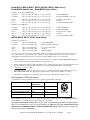
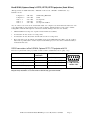
JED T440 Simple Projector Controller users manual version V021 part B
(Ed Schoell rev: Nov 17th 2008)
Table of Contents
Acer projector family
1
BenQ MP5/7xx, SP820,Opt Gr3 2/3
Epson VP21, IR to X5
4/5
HP projector
6
Hitachi proj
7
InFocus / ASK Proxima
8
LG LCD/Plasma TV
9
Mitsubishi
10/11
NEC LCD TV (& Sherwood), Plasma
and NEC Projector
12/15
Optoma Projector Gr1&2
Panasonic Projector
Plus U5, U7 Projector
Sanyo LCD TV, projector
Sharp
Sony projector
Toshiba projector
Taxan projector
16/17
18/19
20
21/23
24
25
26/27
28
Acer (Code 70 hex), PD727, P1165, P1265, P5260, P5270, P5280, P5370
Channel codes are:
Computer1
Computer2
Computer3
:= '* 0 IR 015' + 0D;
:= '* 0 IR 028' + 0D;
:= '* 0 IR 016' + 0D;
// RGB analog-RGB VGA
// RGB analog- via DVI (some models only)
// DVI digital via DVI
Video1
Video2
Video3
Video4
Video5
:= '* 0 IR 019' + 0D;
:= '* 0 IR 018' + 0D;
:= '* 0 IR 017' + 0D;
:= '* 0 IR 029' + 0D;
:= '* 0 IR 016' + 0D;
// Comp Video
// S-Video
// Component YPbPr via DB15 HDTV
// Component YPbPr DVI or HDMI via adaptor (some models only)
// DVI or HDMI via adaptor
(There may be more codes available for “Wireless” and “HDMI” on newer devices. Update later.)
Any one of these codes can be set into Constant:0/Constant:1 for computer codes and Constant:2/Constant:3 for video
codes. (The default is to have Computer1 (above) as the “Computer” channel and Video1 as the “Video” channel.
Setting OPT1 switch ON will swap Video1 and Video2 channels, making S-Video the video default.)
•
Power on projector connection blink codes available;
•
OPT7 handshake mode not available;
•
Source lock must be turned ON in the “Maintenance” menu;
•
Freeze and mute are toggle mode only in these projectors, so 2-yellow-button mute mode is NOT supported;
•
Audio functions are limited to one (sometimes two) audio input(s) and no output to room speakers. Use a T461 if
audio control is needed.
RS232 connections to 3-Pin DIN Acer projectors.
Mini-DIN 3 socket on projector. Coms at: 9600 DP8N1
Function/Direction
T440 “projector”
Connection
Acer Serial Port
Connector
Ground
Ground
Mini-DIN 3 pin 3 (Gnd)
Data from T440 to projector
Tx
Mini-DIN 3 pin 1 or 2 (RXD)
Reply data from projector to T440
Rx
Mini-DIN 3 pin 2 or 1 (TXD)
1
2
3
Mini-DIN 3
solder side
After installation wiring of any projector to a T440, use a multimeter to check voltages of –9 on BOTH TX and RX pins
in any installation, as described in the troubleshooting part of this manual.
T440 Users manual V021/B, © JED Microprocessors Pty Ltd Nov 17th 2008
Page 1
BenQ MP510, MP610, MP611, MP620, MP720P, MP721 (Code 38 hex),
BenQ MP622 (Code 39 hex), BenQ MP770 (Code 3A hex)
Channel codes for all except MP770 are:
Computer1
Computer2
:= 06 + 14 + 00 + 04 + 00 + 34 + 13 + 01 + 00 + 60;
:= 06 + 14 + 00 + 04 + 00 + 34 + 13 + 01 + 01 + 61;
// Analog RGB DB15
// DVI (Analog RGB) (some only)
Video1
Video2
Video3
:= 06 + 14 + 00 + 04 + 00 + 34 + 13 + 01 + 04 + 64;
:= 06 + 14 + 00 + 04 + 00 + 34 + 13 + 01 + 05 + 65;
:= 06 + 14 + 00 + 04 + 00 + 34 + 13 + 01 + 03 + 63;
// Composite Video RCA
// S-Video
// Component YPbPr via DB15
Channel codes for MP770 are:
Computer1
Computer2
:= 06 + 14 + 00 + 04 + 00 + 34 + 13 + 01 + 00 + 60;
:= 06 + 14 + 00 + 04 + 00 + 34 + 13 + 01 + 02 + 62;
// Analog RGB DB15
// DVI (Analog RGB)
Video1
Video2
Video3
:= 06 + 14 + 00 + 04 + 00 + 34 + 13 + 01 + 05 + 65;
:= 06 + 14 + 00 + 04 + 00 + 34 + 13 + 01 + 06 + 66;
:= 06 + 14 + 00 + 04 + 00 + 34 + 13 + 01 + 01 + 61;
// Composite Video (RCA)
// S-Video
// Component YPbPr via DB15
MP722, MP723, MP771, SP870 (Code 3D hex)
Channel codes for these are:
Computer1
Computer2
:= 0D + '*sour=rgb#' + 0D;
:= 0D + '*sour=dvia#' + 0D;
// Analog RGB DB15
// DVI-A (Analog) some only
Video1
Video2
Video3
:= 0D + '*sour=vid#' + 0D;
:= 0D + '*sour=svid#' + 0D;
:= 0D + '*sour=dvid#' + 0D;
// Composite Video RCA
// S-Video
// DVI-D (Digital)
Any one of these codes can be set into Constant:0/Constant:1 for computer codes and Constant:2/Constant:3 for video
codes. (The default is to have Computer1 (above) as the “Computer” channel and Video1 as the “Video” channel.
Setting OPT1 switch ON will swap Video1 and Video2 channels, making S-Video the video default.)
•
OPT7 handshake mode and power on panel connection blink codes available (not MP722/MP723/MP771/SP870);
•
Source scan must be turned off using normal on-screen menu options;
•
RS232 communications must be enabled and baud rate set to 19200 in the secret factory setup menu. We have been
requested by BenQ not to include these instructions in a general manual like this: Please contact JED at:
[email protected] for details.
•
Freeze and mute are toggle mode only in these projectors, so 2-yellow-button mute mode is NOT supported (is in
MP722/MP723/MP771/SP870 as this has mute state read-back. Set T461 audio and OPT7 to use this);
•
Audio functions are limited to one audio input and no output. Use a T461 if audio control is needed.
BenQ projectors: RS232 Connection
(Communications runs at 19200 8N1. Projectors use a male 8-pin mini-DIN on the cable
Function
T440 “projector”
Connection
DIN 8-pin BenQ,
Ground
Pin 1
Pin 4
Serial TX out to projector
Pin 2
Pin 1
Serial RX into T440 from proj.
Pin 3
Pin 7
CTS out to projector
Pin 4
Not used
1
2
3
4
6
7
5
8
Mini-DIN 8
solder side
Even though some BenQ manuals show a D sub 9 connector, the tested projectors all have mini-DIN 8-pin sockets.
After installation wiring of any projector to a T440, use a multimeter to check voltages of –9 on BOTH TX and RX pins
in any installation, as described in the troubleshooting part of this manual.
Note: MP722/MP723/MP771/SP870: These projectors have a nasty hang-up habit, where coms just stops and
only recovery is a 240v power cycle (i.e. at the power point or by pulling the power plug. Until BenQ fix this, DO
NOT INSTALL IT POWERED FROM A CEILING POWER POINT. Instruct the user on how to “power cycle”
the projector if it stops communicating.
T440 Users manual V021/B, © JED Microprocessors Pty Ltd Nov 17th 2008
Page 2
BenQ SP820, Optoma Group 3: EP771, EP772, EP774 projectors (Code 3B hex)
(Message formats are ASCII with format: “~PN<CR>” for Power On, “~SR<CR>” for RGB select, etc.)
Channel codes are:
Computer1 :=
Computer2 :=
'~SR' + 0D;
'~SD' + 0D;
// RGB analog-RGB VGA
// DVI
Video1 :=
Video2 :=
Video3 :=
'~SV' + 0D;
'~SS' + 0D;
'~SY' + 0D;
// Comp Video
// S-Video
// Component via DB15
Any one of these codes can be set into Constant:0/Constant:1 for computer codes and Constant:2/Constant:3 for video
codes. (The default is to have Computer1 (above) as the “Computer” channel and Video1 as the “Video” channel.
Setting OPT1 switch ON will swap Video1 and Video2 channels, making S-Video the video default.)
•
OPT7 handshake mode and power on panel connection blink codes available;
•
You must turn off “Auto Source” in “Config” menu;
•
You must turn off “Auto Power Off” and ‘Direct Power On” in “Config” menu.
•
Freeze and mute toggle only with the “Freeze/Mute” keyboard. No LEDs flash in the “Mute” state. No 2-yellowbutton mute is provided with a “Volume” keyboard as the limited projector codes cannot command absolutely or
read back the mute state;
RS232 connections to BenQ SP820, Optoma EP771/772 projector with D9
These use a 9-pin-D9 male on the proj, female on cable. Comms is at 9600 baud, 8 bits, no parity, 1 stop.
Function/Direction
T440 “projector”
Connection
“Serial” Port Connector
Ground
Ground
9-pin D-sub pin 5
Data from T440 to projector
Tx
9-pin D-sub pin 3 (RXD)
Reply data from projector to T440
Rx
9-pin D-sub pin 4 (TXD)
Plus 9 volt CTS/DTR to projector
n/c
n/c
1
2
6
3
7
4
8
5
9
D-sub 9 female
solder side
After installation wiring of any projector to a T440, use a multimeter to check voltages of –9 on BOTH TX and
RX pins in any installation, as described in the troubleshooting part of this manual.
T440 Users manual V021/B, © JED Microprocessors Pty Ltd Nov 17th 2008
Page 3
Epson VP21 projectors (Code 0C hex)
This family has many members with a range of channel messages.
Typical models are: EMP 30/52/53/54/61/73/74/81/62/82/83/400W/600/800/810/811/820/821/822/828/830/835/830 /
EMP 6100/6000/6110/1810/1815/1825/7800/7850/7900/7950/8300/9300/S1/S1H
In the back of each user’s manual is a list of typical channel selection messages,
Channel codes are:
Computer1
Computer2
Computer3
Computer4
Computer5
:= 'SOURCE 11' + 0D;
:= 'SOURCE 21' + 0D;
:= 'SOURCE 30' + 0D;
:= 'SOURCE 31' + 0D;
:= 'SOURCE B1' + 0D;
// DSUB1 VGA analog-RGB
// DSUB2 VGA analog-RGB
// INPUT3 DVI-D
// INPUT3 D-RGB
// INPUT4 BNC analog-RGB
Video1
Video2
Video3
Video4
Video5
Video6
Video7
Video8
Video9
Video10
Video11
Video12
Video13
:= 'SOURCE 41' + 0D;
:= 'SOURCE 42' + 0D;
:= 'SOURCE 14' + 0D;
:= 'SOURCE 24' + 0D;
:= 'SOURCE 15' + 0D;
:= 'SOURCE 25' + 0D;
:= 'SOURCE 30' + 0D;
:= 'SOURCE 31' + 0D;
:= 'SOURCE B2' + 0D;
:= 'SOURCE B3' + 0D;
:= 'SOURCE B4' + 0D;
:= 'SOURCE C4' + 0D;
:= 'SOURCE C5' + 0D;
// Comp Video
// S-Video
// Component on DSUB1 or YCbCr on DSUB1
// Component on DSUB2 or YCbCr on DSUB2
// YCbCr on DSUB1
// YCbCr on DSUB2
// INPUT3 DVI-D
// INPUT3 D-RGB
// INPUT4 BNC COMPONENT RGB-Video
// INPUT4 BNC COMPONENT YCbCr
// INPUT4 BNC COMPONENT YPbPr
// INPUT5 BNC COMPONENT YCbCr
// INPUT5 BNC COMPONENT YPbPr
Any one of these codes can be set into Constant:0/Constant:1 for computer codes and Constant:2/Constant:3 for video
codes. (The default is to have Computer1 (above) as the “Computer” channel and Video1 as the “Video” channel.
Setting OPT1 switch ON will swap Video1 and Video2 channels, making S-Video the video default.)
•
OPT7 handshake mode and power on panel connection blink codes available.
RS232 connections to Epson ESC-VP21 projectors
These use a 9-pin-D9 male on the projector, female on cable. Communications is at 9600 baud 8N1.
Function/Direction
T440 “projector”
Connection
Epson ESC-VP21 “Control”
Port Connector
Ground
Ground
9-pin D-sub pin 5
Data from T440 to projector
Tx
9-pin D-sub pin 2 (RXD)
Reply data from projector to T440
Rx
9-pin D-sub pin 3 (TXD)
Plus 9 volt CTS/DTR to projector
N/C
N/C
1
2
6
3
7
4
8
5
9
D-sub 9 female
solder side
After installation wiring of any projector to a T440, use a multimeter to check voltages of –9 on BOTH TX and RX pins
in any installation, as described in the troubleshooting part of this manual.
T440 Users manual V021/B, © JED Microprocessors Pty Ltd Nov 17th 2008
Page 4
Epson X5, X5E (etc) IR controlled projectors (Code A0 hex)
This family uses InfraRed communications with the projector via a stick-on “bug” IR transmitter placed over the IR
window on the back of the projector. It simulates the IR codes sent by the hand-held remote control, and unfortunately
the functions are limited by the projector’s lack of absolute command codes in the IR sequences. Thus there are no
absolute commands for “Video”, “Computer 1”, etc: rather the keyboard (Code 1) has a green button marked “Source /
On” which sends the “Power” command to the projector once, but does not send a “Set Source” command automatically
after warm-up. The red LED comes on immediately on power up with no flashes, and the green LED flashes during
warmup and glows continuously in the ON state. Pressing the OFF button sends the “POWER” IR message twice and
the red LED blinks during the cool-down time, then glows steadily.
The projector will start on the same source channel it was displaying when switched OFF. Pressing the “Source / On”
button again (after warm-up) will index the projector through available sources, but it will only stop on a source if a
valid input is being fed into that input when the projector is looking at that channel. If there is no input at that
point, it will not change to it, but just put up a message screen. If a valid signal is then applied, the “Source / On” button
will need to be pressed again to get it to lock onto the new source.
Models which run with this set of IR commands and IR modulation frequency of 38Khz are: EMP 740/745/737/732,
EMP765/760/755/750/X3/ S3/S4. This family of projectors all use Device-code 8355h and use “NEC” format.
User’s manuals are at: http://tech.epson.com.au/downloads/index.asp?select=7&sCategory=
A new keyboard layout has been designed for this IR mode operation, designated “Code 1”. It provides incremental
volume Up/Down keys, and the current volume level is shown on the projected image for a few seconds. The red and
green LEDs follow the current state of the projector, but if the projector gets out of step with the controller (eg by the
projector being ON when the red OFF led is showing), pressing the OFF button once (in the projector OFF state) will
send the “POWER” IR message twice (with a 1-second separation) which will get things back into step (both OFF).
Because there is no feedback serial path to the controller, OPT7 status read-back is not possible.
There is only one audio input for this projector. Operation with the T461 audio mixer (OPT7) is NOT possible, as there
is no way the controller knows which video source is in use, to command the T461 audio source switching to follow
video source.
(Freeze and mute are not supported at this stage. Two-button-mute mode is not supported either.)
Wiring
The IR transmitting bug is wired to the IR output socket J2 with the shield of the cable connected to the ground pin and
the centre conductor to the “+IR” pin. The signal is current limited (24mA pulses), so no series resistors are needed in
the cable.
As the IR bug wire is only 2M long it will usually be extended, and CAT5 cable is OK for this, but it must be via its own
twisted pair (colour plus colour-with-white). (We have successfully tested this with 50M of CAT5E cable.)
If the CAT5 connector and cable is used runs from CAT5 connector J6, the IR signal runs via a twisted pair of wires via
this cable, but link L1 must be moved from Tx (it’s position in RS232 mode) to IR (as needed for IR mode).
Code 1 keyboard:
T440 Users manual V021/B, © JED Microprocessors Pty Ltd Nov 17th 2008
Page 5
HP vp6320/6321/6325, xp8010/8020 (code 48 hex), ep7120/7122 (Code 49 hex)
Manuals available on line:
HP vp6300 manual: http://www.projectorcentral.com/pdf/projector_manual_2885.pdf
HP ep7120/7122 manual:
http://h10025.www1.hp.com/ewfrf/wc/document?lc=en&cc=us&docname=c00216274&product=427168&dlc=en&print
able=yes&encodeUrl=true&
HP xp8010 manual: http://h10032.www1.hp.com/ctg/Manual/bpq04040.pdf
Channel codes are:
Computer1
Computer2
Computer3
Computer4
Computer5
:= '*RSRC=1' + 0D;
:= '*RSRC=2' + 0D;
:= '*RSRC=6' + 0D;
:= '*RSRC=7' + 0D;
:= '*RSRC=8' + 0D;
// VGA1 Analog RGB DB15 vp632x, xp802x, Code 48
// VGA2 Analog RGB DB15 on xp8010/20, Code 48
// RGBHV xp8010/20, Code 48
// M1 Graphics (DVI) xp8010/20, Code 48
// DVI vp63xx, not analog, Code 48
Computer1 := '*RSRC=8' + 0D;
// VGA1 Analog RGB via DVI to DB15 adaptor (ep712x, Code 49)
Video1
Video2
Video3
Video4
Video5
Video6
// Composite Video RCA all
// S-Video all
// Component Video YPbPr xp632x/xp8010/20
// RGBHV xp8010/20, Code 48
// M1 Graphics (DVI) xp8010/20, Code 48
// DVI vp63xx, not analog, Code 48
:= '*RSRC=3' + 0D;
:= '*RSRC=4' + 0D;
:= '*RSRC=5' + 0D;
:= '*RSRC=6' + 0D;
:= '*RSRC=7' + 0D;
:= '*RSRC=8' + 0D;
Any one of these codes can be set into Constant:0/Constant:1 for computer codes and Constant:2/Constant:3 for video
codes. (The default is to have Computer1 (above) as the “Computer” channel and Video1 as the “Video” channel.
Setting OPT1 switch ON will swap Video1 and Video2 channels, making S-Video the video default).
•
Setting OPT2 switch ON will send an Auto Pixel Align message 30 seconds after selecting a computer channel;
•
Pressing a “Computer” channel key when already selected will instead send a Auto Pixel Align whenever needed;
•
For ep712x use Code 49 on the Sw2/3, and use DVI-> VGA connector. (No computer 2.)
•
OPT7 handshake mode and power on panel connection blink codes available.
RS232 connections to Hewlett-Packard vp63xx, xp80xx, (probably also ep712x)
These use a 9-pin-D9 male on the proj, female on cable. Comms is at 9600 baud, 8 bits, no parity, and 1 stop.
Function/Direction
T440 “projector”
Connection
“Serial” Port Connector
Ground
Ground
9-pin D-sub pin 5
Data from T440 to projector
Tx
9-pin D-sub pin 2 (RXD)
Reply data from projector to T440
Rx
9-pin D-sub pin 3 (TXD)
Plus 9 volt CTS/DTR to projector
N/c
1
2
6
3
7
4
8
5
9
D-sub 9 female
solder side
After installation wiring of any projector to a T440, use a multimeter to check voltages of –9 on BOTH TX and RX pins
in any installation, as described in the troubleshooting part of this manual.
T440 Users manual V021/B, © JED Microprocessors Pty Ltd Nov 17th 2008
Page 6
Hitachi projectors (Code 44 hex, single audio control, Code 45, “by channel” audio)
This family has a compact set of “BE EF” hex commands consistent across the models. Two code groups are provided:
Code 44 is used when there is an audio in for typically each RGB channel but one audio shared by all video inputs.
There is only one pair of commands for audio Inc/Dec and the level of all channels is controlled by this one pair of
commands. So if a level has been dropped for a RGB channel, the audio level is down for the Video input and needs to
be manually adjusted up. These are typically many older models (excluding 3-byte code: CP-X935 to X970.)
Also supported by code 44 are: 3M-MP8746/MP8747/MP8775, 3M-X45, 3M-X55, 3M-X75, 3M-X70, 3M-X80,
ELMO EDP-S10, VIEWSONIC PJ510/PJ853/PJ656/PJ552/PJ562/PJ750/PJ862/PJ1165/PJ1172/PJ1065, also
InfocusLP800 (Hitachi PJ-TX10 does have Code 44 audio.)
Code 45 is used when there are a number of audio inputs (2, 3 or 4) but these are
unallocated to a video channel. These must be manually allocated using the
projector menu system to suit the audio sources, cables and connectors on site, but
any audio input can typically be allocated to any video/RGB input. Audio channels
can be shared or a channel set to have no audio. A typical menu sequence is to go to:
Menu -> Advanced menu -> Audio -> Audio, which gives a table of (a variable number
of) channel names down the left column, audio inputs by number across the top, and a
matrix of buttons which allows one allocation button or an OFF button to be selected
per channel. Use the “down” button to select a channel, and the “left” or “right” buttons
to move the “dot” to select that channel’s audio. Move to the “quit” position to save and use the “left” to exit the menu.
Typical Code 45 models are: CP-X2, CP-X6, CP-X200, CP-X205, CP-X251, CP-X253, CP-X245, CP-X255, CP-X256,
CP-X260, CP-X265, CP-X268, CP-X300, , CP-X305, CP-X308, CP-X400, CP-X417, CP-X505, CP-X600, CP-X605,
CP-X608, ED-X10, ED-X12, ED-X15, ED-X22
VIEWSONIC PJ759/PJ758/PJ760, PJ1158, 3M-X64, 3M-X90
Following have no audio so can use either code: PJ-TX100, TX200, TX300
In the back of each user’s manual is a list of typical channel selection messages, and manuals of most Hitachi projectors
are available at: http://www.projectorcentral.com/Hitachi.htm or http://www.hitachi.com/products/personal/av.html
Channel codes are:
Computer1 := BE + EF + 03 + 06 + 00 + FE + D2 + 01 + 00 + 00 + 20 + 00 + 00;
Computer2 := BE + EF + 03 + 06 + 00 + 3E + D0 + 01 + 00 + 00 + 20 + 04 + 00;
Computer3 := BE + EF + 03 + 06 + 00 + 0E + D2 + 01 + 00 + 00 + 20 + 03 + 00;
// Analog RGB 1 DB15
// Analog RGB 2 DB15/ BNC
// Digital/M1D/DVI/HDMI
Video1
Video2
Video3
// Composite Video RCA
// S-Video
// Component RCA
:= BE + EF + 03 + 06 + 00 + 6E + D3 + 01 + 00 + 00 + 20 + 01 + 00;
:= BE + EF + 03 + 06 + 00 + 9E + D3 + 01 + 00 + 00 + 20 + 02 + 00;
:= BE + EF + 03 + 06 + 00 + AE + D1 + 01 + 00 + 00 + 20 + 05 + 00;
Any one of these codes can be set into Constant:0/Constant:1 for computer codes and Constant:2/Constant:3 for video
codes. (The default is to have Computer1 (above) as the “Computer” channel and Video1 as the “Video” channel.
Setting OPT1 switch ON will swap Video1 and Video2 channels, making S-Video the video default.)
•
OPT7 handshake mode and power on panel connection blink codes available.
RS232 connections to Hitachi and 3M, InFocus and Elmo Hitachi-made projectors
These use either a D-sub 15 shrink jack pin connector, female on cable, or a DB9, female on cable. Coms at 19200 8N1:
Function/ Direction
T440 “projector”
Connection
Hitachi “Control” Port
Connector 15-pin shrink
Hitachi “Control” Port
Connector, DB9 (some)
Ground
Ground
Pin 6, 7 and 10. (Use all)
Pin 5
Data from T440 to projector
Tx
Pin 13
Pin 2
Reply data from proj. to T440
Rx
Pin 14
Pin 3
Plus 9 volt CTS/DTR
N/C
N/C
N/C
After installation wiring of any projector to a T440, use a multimeter to check voltages of –9 on BOTH TX and RX pins
in any installation, as described in the troubleshooting part of this manual. CTS is NOT needed.
T440 Users manual V021/B, © JED Microprocessors Pty Ltd Nov 17th 2008
Page 7
InFocus projectors (Code 58 hex) (also ASK/Proxima A1100/A1200/A1300)
Currently only IN2102/EP, IN2104/EP and IN2106/EP, but possibly will drive other similar units.
In the back of each user’s manual is a list of typical channel selection messages, and manuals of InFocus projectors are
available at: http://www.infocus.com/support.aspx , enter projector model number into the “Projector QuickFind”
window to get to an individual model’s page, and click the “documents” tab for codes.
Channel codes are:
Computer1
Computer2
:= '(SRC0)';
:= '(SRC1)';
// DSUB1 VGA analog-RGB
// DSUB2 VGA analog-RGB
Video1
Video2
:= '(SRC2)';
:= '(SRC3)';
// Comp Video
// S-Video
Any one of these codes can be set into Constant:0/Constant:1 for computer codes and Constant:2/Constant:3 for video
codes. (The default is to have Computer1 (above) as the “Computer” channel and Video1 as the “Video” channel.
Setting OPT1 switch ON will swap Video1 and Video2 channels, making S-Video the video default.)
•
The current projectors supplied in Australia MUST HAVE A SOFTWARE UPGRADE BEFORE
INSTALLATION from 1.01 to 1.07 or later, otherwise operation is unreliable (comms hangs up) and
handshake response requests are incorrectly interpreted as a “power down” command, due to a firmware bug in
the projector;
•
On panel connection blink codes and OPT7 handshake mode are available;
•
Freeze command is available, so “Code A” keyboard OK;
•
Two-yellow button “Mute” command is supported;
•
The projector is set to Auto Source = 0 (Off) automatically from the T440 by a command string; and
•
There is about a 10 second delay after pressing OFF before the lamp goes out and “Cooldown” starts.
RS232 connections to InFocus only IN2102/EP, IN2104/EP and IN2106/EP with D9
These use a 9-pin-D9 male on the proj, female on cable. Comms is at 115,200 baud, 8 bits, no parity, 1 stop.
Function/Direction
T440 “projector”
Connection
“Serial” Port Connector
Ground
Ground
9-pin D-sub pin 5
Data from T440 to projector
Tx
9-pin D-sub pin 2 (RXD)
Reply data from projector to T440
Rx
9-pin D-sub pin 3 (TXD)
Plus 9 volt CTS/DTR to projector
n/c
n/c
1
2
6
3
7
4
8
5
9
D-sub 9 female
solder side
After installation wiring of any projector to a T440, use a multimeter to check voltages of –9 on BOTH TX and
RX pins in any installation, as described in the troubleshooting part of this manual.
T440 Users manual V021/B, © JED Microprocessors Pty Ltd Nov 17th 2008
Page 8
LG LCD/Plasma display/TV (Code 18, 19, 1A and 1B hex)
In the back of each “Owner’s manual” is a list of “input select” codes … examine this table to determine the family.
There are over a 100 different displays in the “kb” LG family, and codes 18 and 19 cover the “kb” codes group (see the
manuals). There are several allocations used, but all use numbers in the 6 … 9 range for RGB analog computer, so all
these are drivable by the code, some may need manual (i.e. at setup time) allocation to constants 0 … 3. AV1/2 code can
vary too, but usually in the 0 … 5 range. Devices are, LCD TV 32/37/42/47/52 LB9/LC7/LC2, and plasma TV 42/50/60
PB2/4/PC5/PY3. Choice of codes 18 or 19 determines TV type, Analog or Digital.
The newer “xb” family, with codes 1A and 1B, cover the LG3, LG5, LG6 and LG7 family and use a single hex byte
after the ASCII select string, with the top 4 bits (5x, 9x, 2x, 4x) selecting an input type (AV, Component, etc) and the
low 4 bits the input number (x0 or x1). Choice of codes 1A or 1B determines TV type, Analog or Digital.
(Another, older, group uses an “i” as a leading character; these are NOT drivable with the Code 18/19/1A/1B driver.)
Function code
“kb” strings,
code 18, 19 hex
“xb” strings,
code 1A, 1B hex
Comments
Computer1
'kb 00 6' + 0D
'xb 00 ' + 50 + 0D
Select RGB-PC (sometimes RGB-DTV on older)
Computer2
'kb 00 7' + 0D
'xb 00 ' + 90 + 0D
Select HDMI-1 (sometimes RGB-PC on older)
Video1
'kb 00 2' + 0D
'xb 00 ' + 20 + 0D
AV1 Video/S-Video
Video2
'kb 00 3' + 0D
'xb 00 ' + 21 + 0D
AV2 Video/S-Video (some only)
Video3
'kb 00 4' + 0D
'xb 00 ' + 40 + 0D
Component 1 Video YPbPr
Video4
'kb 00 5' + 0D
'xb 00 ' + 41 + 0D
Component 2 Video YPbPr
Video5
'kb 00 7' + 0D
'xb 00 ' + 90 + 0D
Select HDMI-1 (sometimes RGB-PC on older)
Video6
'kb 00 8' + 0D
'xb 00 ' + 91 + 0D
Select HDMI-2 (sometimes HDMI-1 or DVI on older)
Any one of these codes can be set into Constant:0/Constant:1 for computer codes and Constant:2/Constant:3 for video
codes. (The default is to have Computer1 (above) as the “Computer” channel and Video1 as the “Video” channel.
Setting OPT1 switch ON will swap Video1 and Video2 channels.)
TV := 'kb 00 0' + 0D; or := 'xb 00 ' + 00 + 0D;
TV := 'kb 00 1' + 0D; or := 'kb 00 ' + 10 + 0D;
// TV Digital (Code 18 or 1A hex selects)
// TV Analog (Code 19 or 1B hex selects)
This panel can be used with a number of keyboards:
•
With a “Code 9” or “Code B” keyboard, with buttons selecting “Video” and ‘Computer”, with “Volume Up/Dn”;
•
With a “Code E” keyboard, with buttons selecting “TV”, “Video” and “Computer”, with TV channel Up/Down
and Volume control keys. (The TV channel commands send incremental (i.e. up and down) commands), so the
limits are set in the panel.)
•
No OPT7 handshake mode or power on panel connection blink codes available.
•
Freeze command is not available.
RS232 connections to LG LCD, LG Plasma and Zenith flat screens
These use a 9-pin-D9 male on the panel, female on cable. Comms is at 9600, 8N1
Function/Direction
T440 “projector”
Connection
Panel RS232 Port
Connector
Ground
Ground
9-pin D-sub pin 5
Data from T440 to projector
Tx
9-pin D-sub pin 3 (RXD)
Reply data from projector to T440
Rx
9-pin D-sub pin 2 (TXD)
Plus 9 volt CTS/DTR to projector
N/C
N/C
1
2
6
3
7
4
8
5
9
D-sub 9 female
solder side
After installation wiring of any projector to a T440, use a multimeter to check voltages of –9 on BOTH TX and RX pins
in any installation, as described in the troubleshooting part of this manual.
Some have clamp diodes on signal lines so voltages may be limited to -0.7 volts and plus 5v signal pulses.
T440 Users manual V021/B, © JED Microprocessors Pty Ltd Nov 17th 2008
Page 9
Mitsubishi projector families: Codes 24 to 28 hex
In the back of some user manuals is a list of RS232 control messages.
Also, see master RS232 code list at: http://www.mitsubishi-presentations.com/customercare/projector_tools.html (There
are some confusions is this site, eg the DX300 link calls up the X300, so to get the XD300/350 sheet use the XD350.)
Volume range settings determine what codes family to select: Audio is done either with an “Absolute” command,
“00VL” followed by a decimal 2-digit number, eg “00VL21<CR>”, or an increment/decrement command “00r06
<CR>” and “00r07 <CR”.
For the absolute volume controlled projectors, there is a paragraph in the manual section or document called
“Controlling the projector using a personal computer” called “Volume Commands”. Look in there for the volume range,
eg 00 – 31 in the box after the VL command definition. Select a control code from the following table:
Volume range
Code group on hex switches
Volume range
Code group on hex switches
00-21
$24
00-60
$26
00-31
$25
00-100
$27
Note: Recently we have found some Mit. Projectors have different audio control
ranges than the Mit. manual states. If you cannot get the full range, try a diff. code.
Some model types for code group 24 hex, 00-21 range:
EX10U, ES-EX100U, HC100, S/XD420U, S/XD430U, HC900/E, WD2000, WL639U, XD435U, XD400U, XD450U,
XD460U, XD470U, XD480U, XD490U, XD500, XD510U, XD520U, XD2000U, XL6U
Some model types for code group 25 hex, 00-31 range:
FL7000U, S/XL4U, XL5U, SL6U, XL8U, XL9U, S/XL25U, XL30U, X200E, S/XD200U, XD300U, XD350U, X390U,
X400U, SX490U, X500U, XL550U, XL650U, XL1550U, XL2550U, XL5900U, XL5950U, XL5980U/LU,
InFocus LP1200
Some model types for code group 26 hex, 00-60 range:
S/XL1U, S/XL2U, S/X50U, SA51U, X70/U, X80U
Some model types for code group 27 hex, 00-100 range:
SD105U, S/XD206U:
Some model types for code group 28 hex, no audio or inc/dec audio only range:
If there is no “Volume commands” paragraph (or no audio in the projector), use the incremental control driver selection,
code $28.
No audio: HC1100, HC1500, HC3000, HC3100, HC4900, HC5000, HD1000, HD4000
Inc/dec audio: X100E, S/X120E, S/X250U, S290U, X300U
Channel codes are:
Computer1 :=
Computer2 :=
Computer3 :=
Computer4 :=
'00_r1' + 0D;
'00_r2' + 0D;
'00_d1' + 0D;
'00_d2' + 0D;
// RGB 1 VGA analog-RGB
// RGB 2 VGA analog, sometimes DVI analog
// DVI Analog 1
// DVI Analog 2
Video1 :=
Video2 :=
Video3 :=
Video4 :=
Video5 :=
'00_v1' + 0D;
'00_v2' + 0D;
'00_c1' + 0D;
'00_d1' + 0D;
'00_d2' + 0D
// Vid composite 1 or S-Video 1
// Vid composite 2 or S-Video 2
// Component
// DVI or HDMI 1
// DVI or HDMI 2
Any one of these codes can be set into Constant:0/Constant:1 for computer codes and Constant:2/Constant:3 for video
codes. (The default is to have Computer1 (above) as the “Computer” channel and Video1 as the “Video” channel.
Setting OPT1 switch ON will swap Video1 and Video2 channels.)
•
OPT7 handshake mode and power on panel connection blink codes available;
T440 Users manual V021/B, © JED Microprocessors Pty Ltd Nov 17th 2008
Page 10
RS232 connections to Mitsubishi projectors (see also D9 following)
These use an 8 or 9-pin mini-DIN male on the cable. Comms is at 9600 baud, 8 bits, no parity, and 1 stop.
Function/Direction
T440 “projector” Connection
“Serial” Port Connector
Ground
Ground
8 or 9-pin mini-DIN pin 4
Data from T440 to projector
Tx
8 or 9-pin mini-DIN pin 1 (RXD)
Reply data from projector to T440
Rx
8 or 9-pin mini-DIN pin 7 (TXD)
Plus 9 volt CTS/DTR to projector
N/C
N/C
NOTE: Mitsubishi use either an 8 or a 9-pin
connector for RS232 (the 9-pin one has some USB
lines, which are ignored in use with the T440).
Mitsubishi in some cases supply an off-the-shelf
mini-DIN 8 to DB9 and a mini-DIN 9 to DB9 cable
called by them the “RS232C” cable.
After installation wiring of any projector to a T440, use
a multimeter to check voltages of –9 on BOTH TX and
RX pins in any installation, as described in the
troubleshooting part of this manual.
1
2
3
4
6
7
5
3
1
2
4
5
6
8
7
Mini-DIN 8
solder side
8
9
Mini-DIN 9
solder side
RS232 connections to Mitsubishi projectors, D9
These use a 9-pin-D9 male on the proj, female on cable. Comms is at 9600 baud, 8 bits, no parity, and 1 stop.
Function/Direction
T440 “projector”
Connection
“Serial” Port Connector
Ground
Ground
9-pin D-sub pin 5
Data from T440 to projector
Tx
9-pin D-sub pin 2 (RXD)
Reply data from projector to T440
Rx
9-pin D-sub pin 3 (TXD)
Plus 9 volt CTS/DTR to projector
N/c
1
2
6
3
7
4
8
5
9
D-sub 9 female
solder side
After installation wiring of any projector to a T440, use a multimeter to check voltages of –9 on BOTH TX and RX pins
in any installation, as described in the troubleshooting part of this manual.
T440 Users manual V021/B, © JED Microprocessors Pty Ltd Nov 17th 2008
Page 11
NEC NLT-40/46FHD100, Sherwood LF-401-TB5 TV/LCD panel (Codes 1C and 1D),
(Made by “indtek” in Korea as LC-401EB3 and LC-461EB3, also sold by Grundig.)
There are two drivers for this: these are same for Computer and Video, but the TV function can select Full HD Digital
tuner (Code 1C hex) or analog tuner (Code 1D hex)
This family has many members with a range of channel messages.
Channel codes are:
Computer1
Computer2
Computer3
Computer4
:= 'kb 00 7' + 0D
:= 'kb 00 8' + 0D
:= 'kb 00 9' + 0D
:= 'kb 00 A' + 0D
// Select PC-RGB
// Select HDMI-1
// Select HDMI-2
// Select HDMI-3
Video1
Video2
Video3
Video4
Video5
Video6
Video7
Video8
Video9
Video10
:= 'kb 00 2' + 0D;
:= 'kb 00 5' + 0D;
:= 'kb 00 3' + 0D;
:= 'kb 00 4' + 0D;
:= 'kb 00 6' + 0D;
:= 'kb 00 0' + 0D;
:= 'kb 00 1' + 0D;
:= 'kb 00 8' + 0D;
:= 'kb 00 9' + 0D;
:= 'kb 00 A' + 0D;
// AV1 Comp Video
// S-Vid
// AV2 Comp Video
// AV3 Comp Video (side)
// Component
// TV Digital
// TV Analog
// Select HDMI-1
// Select HDMI-2
// Select HDMI-3
Any one of these codes can be set into Constant:0/Constant:1 for computer codes and Constant:2/Constant:3 for video
codes. (The default is to have Computer1 (above) as the “Computer” channel and Video1 as the “Video” channel.
Setting OPT1 switch ON will swap Video1 and Video2 channels, making S-Video the video default.)
TV
TV
:= 'kb 00 0' + 0D;
:= 'kb 00 1' + 0D;
// TV Digital (Code 1C hex selects)
// TV Analog (Code 1D hex selects)
This panel can be used with a number of keyboards:
•
With a “Code 9” or “Code A” keyboard, with buttons selecting “Video” and ‘Computer”, with either “Volume”
(code 9) or “Freeze/Mute” (Code A);
•
With a “Code B-L” or “Code B-P” keyboard, with buttons selecting “Video” and “Computer1” and “Computer2”
with Volume control keys; or
•
With a “Code E” keyboard, with buttons selecting “TV”, “Video” and “Computer”, with TV channel Up/Down
and Volume control keys. (The channel commands send incremental (i.e. up and down) commands), so the limits
are set in the panel.)
(Keyboards B and E combine channel keys with “On” keys.)
•
Panel connection blink codes are available but OPT7 handshake mode in NOT.
RS232 connections to Sherwood TV/LCD panel
These use a RG45 on the LCD, female on cable. Comms is at 9600 baud, 8 bits, no parity, 1 stop.
Function/Direction
T440 “projector”
Connection
RG45 Connector EIA568A
Ground
Ground
Pin 3 (orange-white) &
pin 4 (solid blue)
Data from T440 to projector
Tx
Pin 1, green-white
Reply data from projector to T440
Rx
Pin 2, solid green
After installation wiring of any projector to a T440, use a multimeter to check voltages of –9 on BOTH TX and RX pins
in any installation, as described in the troubleshooting part of this manual.
T440 Users manual V021/B, © JED Microprocessors Pty Ltd Nov 17th 2008
Page 12
NEC LCD: 3000/3210/4000/4010/4020/4610/4620/5220/5710/6520P/L, SC40/SC46,
NEC LCD: M40/M46 Old T1, Old T2, Multeos (new mode),
NEC Plasma: 42XC10/42XP10, 50XC10/50XP10, 60XC10/60XP10
In the back of each user’s manual is a list of typical channel selection messages, and manuals of NEC LCD panels are
available at http://www.nec-display-solutions.co.uk/c/g/uk/en/Service/Home/index.html
Function code
NEC LCD 00_r/00_v
and M40/46 (old codes)
M40/46 Multeos
(new codes)
Comments
Computer1
'00_r2' + 0D
'00600001'
Select RGB-PC
Computer2
'00_r3' + 0D
'00600002'
RGB/HV into BNC sockets
Computer3
'00_r1' + 0D
'00600003'
DVI digital
Video1
'00_v1' + 0D
'00600005'
Composite Video (also S-Video on some)
Video2
'00_v3' + 0D
'00600007'
S-Video
Video3
'00_v2' + 0D
'0060000C'
Component 1 Video YPbPr (RCA)
Video4
'00_h1' + 0D
'00600004'
HDMI
TV
n/a
'0060000A'
Digital TV
Any one of these codes can be set into Constant:0/Constant:1 for computer codes and Constant:2/Constant:3 for video
codes. (The default is to have Computer1 (above) as the “Computer” channel and Video1 as the “Video” channel.
Setting OPT1 switch ON will swap Video1 and Video2 channels, making S-Video the video default.)
•
On panel connection blink codes supported;
•
OPT7 handshake mode is not available;
•
NEC 3000 … 6520, SC40/46 and M40/46 (old codes) ONLY support keyboard codes ”0” and “5”
•
Audio control (Volume up/down keyboards, codes 2, 9, B, and E) and two-yellow button “Mute” command is
ONLY supported in M40/M46 Multeos mode;
•
Freeze is not supported at all;
•
Turn off ECO mode of the panel to enable On/Off control; and
•
TV control (keyboard code ‘E’) is only available for M40/M46 in Multeos mode. It uses absolute channel
settings, so you MUST setup: Constant:A (Lower TV channel setting, “0” assumed if not set to value) and
Constant:B (Upper TV channel setting, “10” assumed if not set to value.)
RS232 connections to NEC LCD with D9
These use a 9-pin-D9 male on the plasma, female on cable. Comms is at 9600 baud, 8 bits, Odd parity, 1 stop.
Function/Direction
T440 “projector”
Connection
“Serial” Port Connector
Ground
Ground
9-pin D-sub pin 5
Data from T440 to projector
Tx
9-pin D-sub pin 2 (RXD)
Reply data from projector to T440
Rx
9-pin D-sub pin 3 (TXD)
Plus 9 volt CTS/DTR to projector
N/C
N/C
1
2
6
3
7
4
8
5
9
D-sub 9 female
solder side
After installation wiring of any projector to a T440, use a multimeter to check voltages of –9 on BOTH TX and RX pins
in any installation, as described in the troubleshooting part of this manual.
T440 Users manual V021/B, © JED Microprocessors Pty Ltd Nov 17th 2008
Page 13
NEC Plasma PX-42/50/60/61, VM/VP/VR/XM/XR, 2/3/4/5/6 (Code: 14hex)
This family has many members with a range of channel messages.
There is a typical RS232 code Operation Manual at: http://www.prokare.com.tr/pdf2/nec_residental_plasma_rs232.pdf
And http://www.nec-display-solutions.co.uk/c/g/uk/en/Service/Home/index.html
Channel codes are:
Computer1 := DF + 80 + 60 + 47 + 01 + 07 + 0E;
Computer2 := DF + 80 + 60 + 47 + 01 + 08 + 0F;
Computer3 := DF + 80 + 60 + 47 + 01 + 0C + 13;
// RGB1 / PC1 DB15
// RGB2 / PC2 5 x BNC
// RGB3 / PC3 DVI-D
Video1
Video2
Video3
Video4
Video5
Video6
Video7
// "Video2" RCA Composite Video
// "Video3" S-VIDEO DIN-4
// "Video1" BNC
// HD1 3 x RCA DTV1/Component
// HD2 5 x BNC DTV2/Component or SCART1/2
// HD3 DVI/HDMI (some only)
// HD4 DVD/HDMI (some only)
:= DF + 80 + 60 + 47 + 01 + 02 + 09;
:= DF + 80 + 60 + 47 + 01 + 03 + 0A;
:= DF + 80 + 60 + 47 + 01 + 01 + 08;
:= DF + 80 + 60 + 47 + 01 + 05 + 0C;
:= DF + 80 + 60 + 47 + 01 + 06 + 0D;
:= DF + 80 + 60 + 47 + 01 + 0E + 15;
:= DF + 80 + 60 + 47 + 01 + 1A + 21;
Any one of these codes can be set into Constant:0/Constant:1 for computer codes and Constant:2/Constant:3 for video
codes. (The default is to have Computer1 (above) as the “Computer” channel and Video1 as the “Video” channel.
Setting OPT1 switch ON will swap Video1 and Video2 channels, making S-Video the video default.)
This panel can be used with a number of keyboards:
•
With a “Code 9” keyboard, with buttons selecting “Video” and ‘Computer”, with “Volume” keys.
•
With a “Code B-L” or “Code B-P” keyboard, with buttons selecting “Video” and “Computer1” and “Computer2”
with “Volume” control keys. (Keyboards combine channel keys with “On” keys.)
•
(There is no point in using a Code A keyboard, as there is no “Freeze” function on plasma screens.
Panel connection blink codes are available but OPT7 handshake mode in NOT.
Audio mute with 2 Vol keys is available, but not video.
RS232 connections to NEC Plasma with D9
These use a 9-pin-D9 male on the plasma, female on cable. Comms is at 9600 baud, 8 bits, Odd parity, 1 stop.
Function/Direction
T440 “projector”
Connection
“Serial” Port Connector
Ground
Ground
9-pin D-sub pin 5
Data from T440 to projector
Tx
9-pin D-sub pin 2 (RXD)
Reply data from projector to T440
Rx
9-pin D-sub pin 3 (TXD)
Plus 9 volt CTS/DTR to projector
“RTS”
9-pin D-sub pin 8(CTS IN)
1
2
6
3
7
4
8
5
9
D-sub 9 female
solder side
After installation wiring of any projector to a T440, use a multimeter to check voltages of –9 on BOTH TX and RX pins
in any installation, as described in the troubleshooting part of this manual.
T440 Users manual V021/B, © JED Microprocessors Pty Ltd Nov 17th 2008
Page 14
NEC projector families: GT60, HT,LT, LT30, NP40, LT60, LT80, MT70, NP1000,
NP4000, WT, VT, (38,400 baud, Code 10 hex)
NEC projector families: VT70, VT80, VT90 (19,200 baud, Code 11 hex)
NEC old or at 9,600 baud (eg with long cable runs): Code 12 hex
Note: Check the projector installation guide/user manual and set hex code to match projector speed.
In the back of each “Installation Guide” is a list of typical channel selection messages.
Also, see master NEC code list at: http://www.nec-display-solutions.co.uk/c/g/uk/en/Service/Home/index.html
Channel codes are:
Computer1
Computer2
Computer3
Computer4
Computer5
Computer6
:= 02 + 03 + 00 + 00 + 02 + 01 + 01 + 09;
:= 02 + 03 + 00 + 00 + 02 + 01 + 02 + 0A;
:= 02 + 03 + 00 + 00 + 02 + 01 + 03 + 0B;
:= 02 + 03 + 00 + 00 + 02 + 01 + 1A + 22;
:= 02 + 03 + 00 + 00 + 02 + 01 + 1F + 27;
:= 02 + 03 + 00 + 00 + 02 + 01 + 20 + 28;
// RGB 1 VGA analog-RGB
// RGB 2 sometimes DVI analog
// DVI Analog
// **DVI Digital OR component (VT770)
// Input Select Viewer
// LAN
Video1
Video2
Video3
Video4
Video5
Video6
Video7
Video8
Video9
Video10
Video11
Video12
:= 02 + 03 + 00 + 00 + 02 + 01 + 06 + 0E;
:= 02 + 03 + 00 + 00 + 02 + 01 + 0B + 13;
:= 02 + 03 + 00 + 00 + 02 + 01 + 07 + 0F;
:= 02 + 03 + 00 + 00 + 02 + 01 + 0C + 14;
:= 02 + 03 + 00 + 00 + 02 + 01 + 10 + 18;
:= 02 + 03 + 00 + 00 + 02 + 01 + 11 + 19;
:= 02 + 03 + 00 + 00 + 02 + 01 + 12 + 1A;
:= 02 + 03 + 00 + 00 + 02 + 01 + 1A + 22;
:= 02 + 03 + 00 + 00 + 02 + 01 + 24 + 2C;
:= 02 + 03 + 00 + 00 + 02 + 01 + 25 + 2D;
:= 02 + 03 + 00 + 00 + 02 + 01 + 29 + 31;
:= 02 + 03 + 00 + 00 + 02 + 01 + 2A + 32;
// Comp Video
// S-Video
// Comp Video 2
// S-Video 2
// Component #1
// Component #2
// Component #3
// **DVI Digital OR component (VT770)
// Slot1-1 GT5000/6000
// Slot1-2 GT5000/6000
// Slot2-1 GT5000/6000
// Slot2-2 GT5000/6000
Any one of these codes can be set into Constant:0/Constant:1 for computer codes and Constant:2/Constant:3 for video
codes. (The default is to have Computer1 (above) as the “Computer” channel and Video1 as the “Video” channel.
Setting OPT1 switch ON will swap Video1 and Video2 channels, making S-Video the video default.)
•
OPT7 handshake mode and power on panel connection blink codes available.
Models HT410/510, LT180, VT70 series, and NP40 series don’t control audio via RS232: use a T461 instead.
RS232 connections to NEC projectors
Most use a male 8-pin mini-DIN. Others, see D9 below.
Function/Direction
T440 “projector”
Connection
“Serial” Port Connector
Ground
Ground
8-pin mini-DIN pin 4
Data from T440 to projector
Tx
8-pin mini-DIN pin 1 RXD)
Reply data from projector to T440
Rx
8-pin mini-DIN pin 7 TXD)
Plus 9 volt CTS/DTR to projector
N/C
N/C
1
2
3
4
6
7
5
8
Mini-DIN 8
solder side
After installation wiring of any projector to a T440, use a multimeter to check voltages of –9 on BOTH TX and RX pins
in any installation, as described in the troubleshooting part of this manual.
These use a 9-pin-D9 male on the projector, female on cable.
Function/Direction
T440 “projector”
Connection
“Serial” Port Connector
Ground
Ground
9-pin D-sub pin 5
Data from T440 to projector
Tx
9-pin D-sub pin 2 (RXD)
Reply data from projector to T440
Rx
9-pin D-sub pin 3 (TXD)
Plus 9 volt CTS/DTR to projector
“RTS”
9-pin D-sub pin 8(CTS IN)
1
T440 Users manual V021/B, © JED Microprocessors Pty Ltd Nov 17th 2008
2
6
3
7
4
8
5
9
D-sub 9 female
solder side
Page 15
Optoma Group 1: DS309, DX609, EP721, EP723, EP727, EP728, EP752, EP761,
EP763 (Code 0D hex)
Optoma Group 2: EP766, EP782/W (Code 0E hex)
(Optoma Group 3: See BenQ SP820 for EP771/772 projectors (Code 3B hex))
In the back of each “User’s Manual” is a list of channel selection messages.
See master Optoma manual/code list at: http://www.optoma.eu/support.aspx
Function code
Group 1
Group 2
Computer1
'~0039 5' + 0D
'~0012 5' + 0D
VGA1
Computer2
'~0039 6' + 0D
'~0012 6' + 0D
VGA2 (some only)
Computer3
Computer4
Comments
'~0012 2' + 0D
'~0012 3' + 0D
Computer5
DVI-D (some only)
'~0012 1' + 0D
Group 1: DVI-A
Group 2: HDMI
'~0012 11' + 0D
Group 2: Wireless
Video1
'~0039 10' + 0D
'~0012 5' + 0D
Composite Video
Video2
'~0039 9' + 0D
'~0012 9' + 0D
S-Video
Video3
Video4
'~0012 8'+ 0D
'~0012 3' + 0D
Video5
'~0012 13' + 0D
VGA1 Component
Group 1: DVI-A (some)
'~0012 2' + 0D
Group 2: VGA2 Component
DVI-D (some only)
Video6
'~0012 1' + 0D
Group 2: HDMI
Video7
'~0012 11' + 0D
Group 2: Wireless
Any one of these codes can be set into Constant:0/Constant:1 for computer codes and Constant:2/Constant:3 for video
codes. (The default is to have Computer1 (above) as the “Computer” channel and Video1 as the “Video” channel.
Setting OPT1 switch ON will swap Video1 and Video2 channels.)
This panel can be used with a number of keyboards:
•
With a “Code 9” or “Code B” keyboard, with buttons selecting “Video” and ‘Computer”, with “Volume Up/Dn”;
•
Freeze command is available, so “Code A” keyboard OK;
•
Two-yellow button “Mute” command is supported;
•
OPT7 handshake mode and power on panel connection blink codes available.
•
The “Source Lock” option in the “Options” menu MUST be turned ON (to stop the projector searching for
other channels when an input is dropped.)
RS232 connections to 3-Pin DIN Optoma Group 1
Mini-DIN 3 socket on projector. Coms at: 9600 DP8N1
Function/Direction
T440 “projector”
Connection
Optoma 3-pin Serial Port
Connector
Ground
Ground
Mini-DIN 3 pin 3 (Gnd)
Data from T440 to projector
Tx
Mini-DIN 3 pin 2 (RXD)
Reply data from projector to T440
Rx
Mini-DIN 3 pin 1 (TXD)
1
2
3
Mini-DIN 3
solder side
After installation wiring of any projector to a T440, use a multimeter to check voltages of –9 on BOTH TX and RX pins
in any installation, as described in the troubleshooting part of this manual.
T440 Users manual V021/B, © JED Microprocessors Pty Ltd Nov 17th 2008
Page 16
RS232 connections to Optoma Group 2: EP776, EP782 projector with D9
These use a 9-pin-D9 male on the proj, female on cable. Comms is at 9600 baud, 8 bits, no parity, 1 stop.
T440 “projector”
Connection
“Serial” Port Connector
Ground
Ground
9-pin D-sub pin 5
Data from T440 to projector
Tx
9-pin D-sub pin 2 (RXD)
Reply data from projector to T440
Rx
9-pin D-sub pin 3 (TXD)
Plus 9 volt CTS/DTR to projector
n/c
n/c
Function/Direction
1
2
6
3
7
4
8
5
9
D-sub 9 female
solder side
After installation wiring of any projector to a T440, use a multimeter to check voltages of –9 on BOTH TX and RX pins
in any installation, as described in the troubleshooting part of this manual.
T440 Users manual V021/B, © JED Microprocessors Pty Ltd Nov 17th 2008
Page 17
Panasonic projectors (Codes $30 to $32, $34)
Good set of current model RS232 codes:
https://eww.pavc.panasonic.co.jp/projector/extranet/main/sitemap/index.html
Code $30: (Group 1): No adr, OSH mute/PON unmute, abs audio, PT-L501/701, L502/702,
L511/711/712, PT-L735, PT-F200, PT-LB50/51/55/60, PT-LC55/56/75/76/80, PT-P1SDE and a lot more;
Code $31: (Group 2): No adr, OSH:1 mute/OSH:0 unmute, abs audio, PT-F100/F100NT/FW100NT,
PT-F200/F200NT, PT-LB75/LB75NT, PT-LB80/LB80NT; and
Code $32: (Group 3): No adr, OSH mute/PON unmute, NO audio, PT-AE900/AX100/AX200, PT-AE2000
Note: Panasonic have used toggle mode in the past for the “shutter” or mute function, which makes it hard to know the
current mute state for the two-yellow-button-mute-mode, and the MUTE key in the freeze/mute keyboard (code A). We
have determined that the use of the OSH command to turn ON the mute mode and the use of the PON (Power On) to
exit mute mode works OK on these (Groups 1 and 3 above). Panasonic have recently made it easier by introducing
absolute shutter control by adding OSH:1 (Shutter ON) and OSH:0 (Shutter OFF) commands which give proper control.
These recent ones are the Group 2 in this family.
Channel codes are:
Computer1
Computer2
Computer3
Computer4
Computer5
:= 02 + 'IIS:RG1' + 03;
:= 02 + 'IIS:RG2' + 03;
:= 02 + 'IIS:HDM' + 03;
:= 02 + 'IIS:HD1' + 03;
:= 02 + 'IIS:NWP' + 03;
// RGB 1 VGA analog-RGB
// RGB 2 VGA analog-RGB
// HDMI
// HDMI 1
// NETWORK
Video1
Video2
Video3
Video4
Video5
Video6
Video7
:= 02 + 'IIS:VID' + 03;
:= 02 + 'IIS:SVD' + 03;
:= 02 + 'IIS:YUV' + 03;
:= 02 + 'IIS:HDM' + 03;
:= 02 + 'IIS:HD1' + 03;
:= 02 + 'IIS:HD2' + 03;
:= 02 + 'IIS:NWP' + 03;
// Vid composite
// S-Video
// COMPONENT
// HDMI
// HDMI 1
// HDMI 2
// NETWORK
Code $34: (Group 4): Address mode, OSH:1 mute/OSH:0 un-mute, abs audio, (Address models:
PT-D3500, PT-D4000, PT-DW5000, PT-DW5100, PT-D5500, PT-D5600, PT-D5700, PT-DW7000,
PT-D7700, PT-D10000, PT-DW10000, PT-D12000, PT-DZ12000, PT-L785 (not PT-L6500/6600)
Channel codes are:
Computer1
Computer2
Computer3
Computer4
Computer5
:= 02 + 'ADZZ;IIS:RG2' + 03;
:= 02 + 'ADZZ;IIS:RG1' + 03;
:= 02 + 'ADZZ;IIS:RG3' + 03;
:= 02 + 'ADZZ;IIS:DVI' + 03;
:= 02 + 'ADZZ;IIS:AUX' + 03;
// DB15-VGA analog-RGB
// BNC (or DB15-VGA analog-RGB PT-L785)
// BNC analog-RGB (PT-L785) on some
// DVI-D
// AUXILARY
Video1
Video2
Video3
Video4
Video5
:= 02 + 'ADZZ;IIS:VID' + 03;
:= 02 + 'ADZZ;IIS:SVD' + 03;
:= 02 + 'ADZZ;IIS:DVI' + 03;
:= 02 + 'ADZZ;IIS:AUX' + 03;
:= 02 + 'ADZZ;IIS:RG1' + 03;
// Vid composite
// S-Video
// DVI-D
// AUXILARY
// RGB 1 BNC/DB15 (can be YCbCr component)
Any one of these codes can be set into Constant:0/Constant:1 for computer codes and Constant:2/Constant:3 for video
codes. (The default is to have Computer1 (above) as the “Computer” channel and Video1 as the “Video” channel.
Setting OPT1 switch ON will swap Video1 and Video2 channels, making S-Video the video default.)
•
Power on panel connection blink codes are provided, but OPT7 handshake mode is NOT;
•
Auto Pixel Align is NOT available;
•
Picture and sound mute is available with two-yellow-button mute mode with a “volume” keyboard;
•
Mute and freeze keyboard code A available;
•
Make sure to turn off “Auto input search” if your projector includes this;
•
Make sure to set the baud rate to 9600 and no parity if an adjustment menu is provided.
T440 Users manual V021/B, © JED Microprocessors Pty Ltd Nov 17th 2008
Page 18
RS232 connections to Panasonic projectors: Three systems in use:
D-SUB 9 Female on projector, male on cable. Comms at 9600 8N1
Function/Direction
T440 “projector”
Connection
Panasonic Serial Port
Connector
Ground
Ground
9-pin D-sub pin 5
Data from T440 to projector
Tx
9-pin D-sub pin 3 (RXD)
Reply data from projector to T440
Rx
9-pin D-sub pin 2 (TXD)
Plus 9 volt CTS/DTR to projector
N/C
N/C
5
4
9
3
8
2
7
1
6
D-sub 9 male
solder side
D-SUB 9 Male on projector, female on cable. Comms at 9600 8N1
Function/Direction
T440 “projector”
Connection
Panasonic Serial Port
Connector
Ground
Ground
9-pin D-sub pin 5
Data from T440 to projector
Tx
9-pin D-sub pin 2 (RXD)
Reply data from projector to T440
Rx
9-pin D-sub pin 3 (TXD)
Plus 9 volt CTS/DTR to projector
N/C
N/C
1
2
6
3
4
8
7
5
9
D-sub 9 female
solder side
Mini-DIN-8 socket on projector. Comms at 9600 8N1
Function/Direction
Ground
T440 “projector”
Connection
Ground
Panasonic Serial Port
Connector
mini-DIN 8 pin 4
Data from T440 to projector
Tx
mini-DIN 8 pin 3 (RXD)
Reply data from projector to T440
Rx
mini-DIN 8 pin 5 (TXD)
Plus 9 volt CTS/DTR to projector
N/C
N/C
1
2
3
4
6
7
5
8
Mini-DIN 8
solder side
After installation wiring of any projector to a T440, use a multimeter to check voltages of –9 on BOTH TX and RX pins
in any installation, as described in the troubleshooting part of this manual.
CTS is NOT needed in units tested, so only connect TX, RX and GND.
T440 Users manual V021/B, © JED Microprocessors Pty Ltd Nov 17th 2008
Page 19
Plus projector families: (Code 40 hex) Plus U5, U7 (not U6xxx or Taxan)
See master Plus code list at: http://www.plus-america.com/pdf/PC_Control_RS232.pdf
Channel codes are:
Computer1
Computer2
Computer3
:= '#SR' + 0D + 0A;
:= '#SA' + 0D + 0A;
:= '#SN' + 0D + 0A;
// RGB 1 VGA analog-RGB
// RGB 2 VGA analog-RGB2 on U7 only, DVI on some
// Network on U7 only
Video1
Video2
Video3
:= '#SV' + 0D + 0A;
:= '#SS' + 0D + 0A;
:= '#SN' + 0D + 0A;
// Comp Video
// S-Video
// Network on U7 only
Any one of these codes can be set into Constant:0/Constant:1 for computer codes and Constant:2/Constant:3 for video
codes. (The default is to have Computer1 (above) as the “Computer” channel and Video1 as the “Video” channel.
Setting OPT1 switch ON will swap Video1 and Video2 channels, making S-Video the video default.)
•
OPT7 handshake mode and power on panel connection blink codes available;
•
Turn off the auto-source feature.
RS232 connections to (all) Plus projectors
U2 and U4 use a short cable with a 9-pin-D9 female one end and a 4-pin USB-style on the other. This cable is supplied
by PLUS, and the hole to plug it in is very small, on the rear terminal panel covered with a stick-on silver plastic film.
U5 has a standard D9 male connector on the rear. U7 has 9-pin mini-DIN. Connections are the same for all four ranges.
Function/Direction
T440
“projector”
Connection
Plus “Control”
Port Connector
9-pin D-sub
Plus “Control”
Port Connector
mini-DIN 9 pin
Ground
Ground
9-pin D-sub pin 5
9pin mini-DIN Pin 4
Data from T440 to projector
Tx
9-pin D-sub pin 3
(RXD)
9-pin mini-DIN,
Pin 1 (RXD)
Reply data from projector to T440
Rx
9-pin D-sub pin 2
(TXD)
9-pin mini-DIN,
Pin 7 (TXD)
Plus 9 volt CTS/DTR to projector
N/C
N/C
N/C
3
1
2
4
5
7
8
6
9
Mini-DIN 9
solder side
After installation wiring of any projector to a T440, use a multimeter to check voltages of –9 on BOTH TX and RX pins
in any installation, as described in the troubleshooting part of this manual.
Baud rate change
This family of projectors can be operated at 115,200 baud or 19,200 baud. As shipped from Plus, communications is at
115,200 baud, and must be set using a PC to 19,200 for use with a T440. Switch to 19,200 as follows:
Connect to a PC via a straight-though serial cable and run HyperTerminal, setting it up to run at 115,200 baud, 8 bit
data, 1 start, 1 stop, no parity, no hardware handshake (8N1). (Unless you have enabled “local echo”, you will not see
the characters as you type them. You can enable echo by going to File->Properties->Settings->ASCII Setup and
ticking Echo typed characters locally.) HyperTerminal is found under Accessories in the Windows system.
Verify communications by typing #QS(CR)(LF) (The “QS” must be upper case. The CR and LF must follow. Send a
CR with the ENTER key, and send the LF by holding down CTRL and pressing ENTER.) The projector should reply
with its status, eg #QS2 if OFF, and #QS6 if warmed up and running. If, OFF, the projector can be turned ON with the
#P1(CR)(LF) command. (The character after the P is a numeric 1.)
Now set it to 19,200 baud by sending a command #CL(CR)(LF) from a PC running HyperTerminal at 115,200 baud. (It
will switch immediately, so the reply will be gibberish.)
Now terminate the HyperTerminal session at 115,200 baud and restart it at 19200 baud, (8N1, no handshake, local echo
enabled). Type #QS(CR)(LF) and verify status reply at 19,200 baud. A #P0(CR)(LF) command powers down the U5.
(The character after the P is a numeric 0.) (The U5 can be reset to 115,200 baud with a #CH(CR)(LF) command.)
The baud rate is held in projector non-volatile memory, so the baud rate setting to 19,200 need be done only once.
(These commands are in Release N of the PLUS manual. Make sure the projector software is up-to-date).
T440 Users manual V021/B, © JED Microprocessors Pty Ltd Nov 17th 2008
Page 20
Sanyo LCD display/TV (Code 0A hex)
Sanyo LCD flat panel LCD42/47XR7
Channel codes are:
Computer1
Computer2
Computer3
:= 02 + 'INP:6' + 03;
:= 02 + 'INP:7' + 03;
:= 02 + 'INP:8' + 03;
// Select VGA
// Select HDMI-1
// Select HDMI-2
Video1
Video2
Video3
Video4
Video5
Video6
Video7
Video8
:= 02 + 'INP:1' + 03;
:= 02 + 'INP:3' + 03;
:= 02 + 'INP:4' + 03;
:= 02 + 'INP:5' + 03;
:= 02 + 'INP:2' + 03;
:= 02 + 'INP:7' + 03;
:= 02 + 'INP:8' + 03;
:= 02 + 'INP:0' + 03;
// Comp Video/S=Vid (on same channel, S-Vid has priority)
// SCART 1 video via adaptor
// SCART 2 video via adaptor
// SCART 2 s-video via adaptor
// Video YPbPr
// Select HDMI-1
// Select HDMI-2
// Select TV
Any one of these codes can be set into Constant:0/Constant:1 for computer codes and Constant:2/Constant:3 for video
codes. (The default is to have Computer1 (above) as the “Computer” channel and Video1 as the “Video” channel.
Setting OPT1 switch ON will swap Video1 and Video2 channels.)
The TV setting uses the following command:
TV
:= 02 + 'INP:0' + 03;
// Select TV
This panel can be used with a number of keyboards:
•
With a “Code 9” or “Code A” keyboard, with buttons selecting “Video” and ‘Computer”, with either “Volume”
(code 9) or “Freeze/Mute” (Code A);
•
With a “Code B-L” or “Code B-P” keyboard, with buttons selecting “Video” and “Computer1” and “Computer2”
with Volume control keys; or
•
With a “Code E” keyboard, with buttons selecting “TV”, “Video” and “Computer”, with TV channel Up/Down
and Volume control keys. The channel commands send absolute channel commands, so the upper and lower limits
must be programmed into Constant:A and Constant:B. (Default is 0 -> 10.)
(Keyboards B and E combine channel keys with “On” keys.)
•
OPT7 handshake mode and power on panel connection blink codes available.
RS232 connections to Sanyo LCD
These use a 9-pin-D9 male on the projector, male on cable. Communications is at 9600 baud 8N1.
Function/Direction
T440 “projector”
Connection
Sanyo “Control” Port
Connector
Ground
Ground
9-pin D-sub pin 5
Data from T440 to projector
Tx
9-pin D-sub pin 3 (RXD)
Reply data from projector to T440
Rx
9-pin D-sub pin 2 (TXD)
Plus 9 volt CTS/DTR to projector
N/C
N/C
5
4
9
3
8
2
7
1
6
D-sub 9 male
solder side
After installation wiring of any projector to a T440, use a multimeter to check voltages of –9 on BOTH TX and RX pins
in any installation, as described in the troubleshooting part of this manual.
T440 Users manual V021/B, © JED Microprocessors Pty Ltd Nov 17th 2008
Page 21
Sanyo, Eiki projectors (Code 02 hex, absolute audio, Code 03 hex, inc. audio, Code
04 hex, C07 video, Code 05 hex, C05 Computer 1)
This family has many members with a range of channel messages.
Sanyo has RS232 code charts on www.sanyo.com.au listing codes for each projector.
Many Eiki, e.g. LC-SB, SD, SE, SX, W, WB, X (most, but not 3-digit ones), XA, XB, XE, XG, XGA, XT.
Not LC-EIP (see Sharp) or XIP2000 or XWP2000 (yet).
Check codes at: http://www.eiki.com/Support/Default.aspx (some older use just C05, C06, C07 codes below).
If absolute audio (Code 02) doesn’t work, use Code 03, which sends incremental audio.
Channel codes are:
Computer1
Computer2
Computer3
Computer4
Computer5
Computer6
Computer7
:= 'C50' + 0D;
:= 'C25' + 0D;
:= 'C52' + 0D;
:= 'C05' + 0D;
:= 'C06' + 0D;
:= 'C81' + 0D;
:= 'C82' + 0D;
// Input 1 Analog RGB DB15
// Input 2 Analog RGB DB15
// Input 1 DVI (PC Digital)
// Input 1 / Slot 1
// Input 2 / Slot 2
// Input 4 / Wired network
// Input 4 / Wireless
Video1
Video2
Video3
Video4
Video5
Video6
Video7
Video8
Video9
Video10
Video11
Video12
Video13
Video14
Video15
:= 'C33' + 0D;
:= 'C34' + 0D;
:= 'C35' + 0D;
:= 'C07' + 0D;
:= 'C23' + 0D;
:= 'C24' + 0D;
:= 'C25' + 0D;
:= 'C26' + 0D;
:= 'C06' + 0D;
:= 'C53' + 0D;
:= 'C54' + 0D;
:= 'C05' + 0D;
:= 'C81' + 0D;
:= 'C82' + 0D;
:= 'C83' + 0D;
// Input 3 Composite Video RCA
// Input 3 S-Video
// Input 3 Y, Pb/Cb, Cb/Cr (Component)
// Input 3 / Slot 3
// Input 2 Composite Video RCA
// Input 2 S-Video/Component RCA
// Input 2 Component 1 RCA
// Input 2 Component 2
// Input 2 / Slot 2
// Input 1 DVI (AV HDCP)
// Input 1 Component
// Input 1 / Slot 1
// Input 4 Composite Video / Wired network
// Input 4 S-Video / Wireless
// Input 4 Component / USB viewer
Any one of these codes can be set into Constant:0/Constant:1 for computer codes and Constant:2/Constant:3 for video
codes. (The default is to have Computer1 (above) as the “Computer” channel and Video1 as the “Video” channel.
Setting OPT1 switch ON will swap Video1 and Video2 channels, making S-Video the video default).
•
Some models (eg PLC-XW55/56) use command C07 for composite video, so use Code 04 hex for these.
•
Some models (eg PLC-XU105) use command C05 for Computer:1, so use Code 05 hex for these.
•
Setting OPT2 switch ON will send an Auto Pixel Align message 30 seconds after selecting a computer channel;
•
Pressing a “Computer” channel key when already selected will instead send a Auto Pixel Align whenever needed;
•
OPT7 handshake mode and power on panel connection blink codes available.
RS232 connections to Sanyo projectors
8-Pin DIN circular connector group: Communications is at 19200 baud, 8N1.
Function/Direction
T440 “projector”
Connection
Control Port Connector
1
Ground
Ground
8-pin DIN pin 4
Data from T440 to projector
Tx
8-pin DIN pin 1 (RXD)
Reply data from projector to T440
Rx
8-pin DIN pin 6 (TXD)
Plus 9 volt CTS/DTR to projector
CTS
8-pin DIN pin 5 (CTS/RTS)
2
3
4
6
7
5
8
Mini-DIN 8
solder side
After installation wiring of any projector to a T440, use a multimeter to check voltages of –9 on BOTH TX and RX pins
in any installation, as described in the troubleshooting part of this manual.
T440 Users manual V021/B, © JED Microprocessors Pty Ltd Nov 17th 2008
Page 22
Sanyo projector PLC-WXU10N (Code 07 hex)
This family has one member with just 5 channel messages.
There is an RS232 code chart at:
http://www.slideandsound.com/pdf/sanyo/projectors/Owners_Manuals/om_PLC-WXU10N.pdf
Channel codes are:
Computer1
Computer2
:= BE + EF + 02 + 06 + 00 + 0B + D2 + 32 + 00 + 00 + 00 + 00 + 00; // RGB 1 VGA
:= BE + EF + 02 + 06 + 00 + 8F + D3 + 36 + 00 + 00 + 00 + 00 + 00; // DVI-D
Video1
Video2
Video3
:= BE + EF + 02 + 06 + 00 + BC + D3 + 35 + 00 + 00 + 00 + 00 + 00; // Comp Video
:= BE + EF + 02 + 06 + 00 + 6D + D2 + 34 + 00 + 00 + 00 + 00 + 00; // S-Video
:= BE + EF + 02 + 06 + 00 + DA + D3 + 33 + 00 + 00 + 00 + 00 + 00; // Component
Any one of these codes can be set into Constant:0/Constant:1 for computer codes and Constant:2/Constant:3 for video
codes. (The default is to have Computer1 (above) as the “Computer” channel and Video1 as the “Video” channel.
Setting OPT1 switch ON will swap Video1 and Video2 channels, making S-Video the video default).
•
The “Input search” function MUST be disabled in the projector;
•
Audio is limited: there is only one stereo RCA input, and NO audio output. There is control (incremental, 0->100
NOT 0->60 as the manual says) via the RS232 control if a “Volume” keyboard is used, but only to the rather weak
internal speaker. Use a T461 if better audio and switching is needed;
•
Freeze and mute toggle only with the “Freeze/Mute” keyboard. No LEDs flash in the “Mute” state. No 2-yellowbutton mute is provided with a “Volume” keyboard as the limited projector codes cannot command absolutely or
read back the mute state;
•
Users can set OPT2 ON to enable sending Automatic Pixel Align 30 seconds after each Computer source
transmission;
•
No “Projector Comms OK” message is available from the projector in Standby;
•
No OPT7 handshake mode or power on panel connection blink codes are available (no status readback is
provided).
RS232 connections to Sanyo PLC-WXU10N
To connect the T440 to these projectors use a mini-DIN 6 male on the cable: Comms is at 19200 baud 8N1.
Function/Direction
T440 “projector”
Connection
Projector Connector
Connector 6-pin mini-DIN
Ground
Ground
Mini-DIN Pins 1, 2
Data from T440 to projector
Tx
Mini-DIN Pin 3 (RXD)
Reply data from projector to T440
Rx
Mini-DIN Pin 5 (TXD)
Plus 9 volt CTS/DTR to projector
N/C
N/C
1
2
3
4
5
6
Mini-DIN 6
solder side
Note: The signal input and output of this projector has clamp diodes and never goes below –0.7 volts or over +5.7
volts, even when connected to the T440.
T440 Users manual V021/B, © JED Microprocessors Pty Ltd Nov 17th 2008
Page 23
Sharp, EIKI EIP projectors (Code 20 hex, absolute audio)
This family has many members with a range of channel messages.
Sharp has RS232 code charts at the back of the Operation Manual for each projector.
Channel codes are:
Computer1 := 'IRGB
Computer2 := 'IRGB
Computer3 := 'IRGB
Computer4 := 'IRGB
Video1 := 'IVED
Video2 := 'IVED
Video3 := 'IVED
Video4 := 'IVED
Video5 := 'IVED
Video6 := 'IVED
Video7 := 'ISEV
Video8 := 'ICMP
Video9 := 'IDVI
1' + 0D;
2' + 0D;
3' + 0D;
4' + 0D;
// RGB 1 VGA analog-RGB
// RGB 2 analog, sometimes DVI analog
// DVI Analog
// DVI Digital
1' + 0D;
2' + 0D;
3' + 0D;
4' + 0D;
5' + 0D;
6' + 0D;
1' + 0D;
1' + 0D;
1' + 0D;
// Comp Video/S-Video / Component 1
// S-Video / Comp Video / Component 2
// Comp Video 2
// S-Video 2
// RGB/COMPONENT on SHARP DT-400, XV-Z2000, EIKI EIP-1500
// DIGITAL MODE on SHARP DT-400, XV-Z2000, EIKI EIP-1500
// S-VIDEO on EIKI_EIP_S200/X200/X350
// COMPONENT on EIKI_EIP_S200/X200/X350
// DVI on EIKI_EIP_S200/X200/X350
Any one of these codes can be set into Constant:0/Constant:1 for computer codes and Constant:2/Constant:3 for video
codes. (The default is to have Computer1 (above) as the “Computer” channel and Video1 as the “Video” channel.
Setting OPT1 switch ON will swap Video1 and Video2 channels.)
•
Some models use IVED 1 for Comp Video, and IVED2 for S-Video, and some use the reverse;
•
OPT7 handshake mode and power on panel connection blink codes available.
RS232 connections to Sharp/Eiki projectors
These use a D-sub 9-pin connector, female or male on cable: (May be via an adaptor cable from projector 9-pin miniDIN) Communications is at 9600 baud 8N1. Some projectors may need this to be set up via an on-screen menu.
Function/Direction
T440 “projector”
Connection
Sharp Control Port
Connector, D-sub 9
Sharp Control Port
Connector DIN 9
Ground
Ground
9-pin D-sub pin 5
9-pin D-sub pin 5
Data from T440 to projector
Tx
9-pin D-sub pin 2
9-pin D-sub pin 2
Reply data from projector to T440
Rx
9-pin D-sub pin 3
9-pin D-sub pin 3
Plus 9 volt CTS/DTR to projector
CTS
unused
unused
After installation wiring of any projector to a T440, use a multimeter to check voltages of –9 on BOTH TX and RX pins
in any installation, as described in the troubleshooting part of this manual.
T440 Users manual V021/B, © JED Microprocessors Pty Ltd Nov 17th 2008
Page 24
Sony (Code 08 hex, Even Parity, Code 09 hex No Parity)
Even parity: SONY VPL-CX61/CX63/CX80/CX85/CX86/CX100/CX120/CX125/CX150/CX155, VPL-ES4/EX4
SONY_FE40/FX40/FX50/FX51/FX52/PX11/PX15/PX35/PX40/PX41: Code 08 hex
No parity: VPL-ES3/EX3: Code 09 hex
A protocol manual is at:
http://www.kavena.se/fileadmin/uploads/downloads/Sony/Projektorer/VPL-FX40/ProtocolRS232FX40.pdf
This family has common codes, but allocate the “Inputs A/B/C/D” differently.
Channel codes are:
Computer1
Computer2
Computer3
Computer4
Video1
Video2
Video3
Video4
Video5
Video6
:=
:=
:=
:=
A9 + 00 + 01 + 00 + 00 + 02 + 03 + 9A;
A9 + 00 + 01 + 00 + 00 + 03 + 03 + 9A;
A9 + 00 + 01 + 00 + 00 + 04 + 05 + 9A;
A9 + 00 + 01 + 00 + 00 + 05 + 05 + 9A;
:= A9 + 00 + 01 + 00 + 00 + 00 + 01 + 9A;
:= A9 + 00 + 01 + 00 + 00 + 01 + 01 + 9A;
:= A9 + 00 + 01 + 00 + 00 + 02 + 03 + 9A;
:= A9 + 00 + 01 + 00 + 00 + 03 + 03 + 9A;
:= A9 + 00 + 01 + 00 + 00 + 04 + 05 + 9A;
:= A9 + 00 + 01 + 00 + 00 + 05 + 05 + 9A;
// Input A VGA analog-RGB
// Input B or Component
// Input C or HDMI
// Input D or DVI
// Composite Video RCA
// S-Video
// Input A (could be component)
// Input B could be component)
// Input C or HDMI
// Input D or DVI
Any one of these codes can be set into Constant:0/Constant:1 for computer codes and Constant:2/Constant:3 for video
codes. (The default is to have Computer1 (above) as the “Computer” channel and Video1 as the “Video” channel.
Setting OPT1 switch ON will swap Video1 and Video2 channels, making S-Video the video default.)
•
OPT7 handshake mode and power on panel connection blink codes available;
•
Pressing a “Computer” channel key when already selected will instead send a Auto Pixel Align whenever needed;
•
Setting OPT2 switch ON will send an Auto Pixel Align message 30 seconds after selecting a computer channel;
•
Picture and sound mute is available with two-yellow-button mute mode, but no Freeze is available.
RS232 connections to Sony projectors and LCD flat panel
These all use a D-sub 9-pin connector, male on cable.
VPL- CX85/86, FX50/51/52, PX11/15/35/40/41 38400 BAUD, Even parity, 1 stop.
VPL- ES3/EX3, 38400 BAUD, No parity, 1 stop.
Function/Direction
T440 “projector”
Connection
Projector Connector
(Male on cable)
Ground
Ground
9-pin D-sub pin 5
Data from T440 to projector
Tx
9-pin D-sub pin 2 (RXD)
Reply data from projector to T440
Rx
9-pin D-sub pin 3 (TXD)
Plus 9 volt CTS/DTR to projector
N/C
N/C
5
4
9
3
8
2
7
1
6
D-sub 9 male
solder side
After installation wiring of any projector to a T440, use a multimeter to check voltages of –9 on BOTH TX and RX pins
in any installation, as described in the troubleshooting part of this manual.
T440 Users manual V021/B, © JED Microprocessors Pty Ltd Nov 17th 2008
Page 25
Toshiba (Codes $50 to $54 hex)
A good collection of protocol manuals is at:
http://www.isd.toshiba.com.au/projectors/projectors/service-manuals.shtml
Code $50: (Group 1.1): TLP-S200/S201/S220/S221, TLP-T400/T401, TLP-T500/T501/T520/T521, TLPT600/T601/T620/T621, and TLP-T700/T701/T720/T721;
Code $51 (Group 1.2): TDP-MT200/MT400;
Code $51 (Group 1.3): TDP-S20/S21/SC21/S25/SC25/SW25/S35/SC35/SW35,
TDP-S80/SW80/S81/T90/TW90/T91/T99/TW99, and TLP-710/711;
Code $51 (Group 1.4): TDP-S8/S10, SW20, TDP-T8/T9/T30/T40/T45/T80/T98,
TLP-250/251/260/261/380/381/550/551/560/561/780/781/790/791, TLP-MT7E, TLP-X10U/11U/20U/21U;
Code $51 (Group 1.5): TDP-D1/D2, TLP-S30/S40/S41/S70/S71, and TLP-T50/T60/T61/T70/T71;
Code $52 (Group 1.6): TLP-450/451/470/471/650/651/670/671/680/681/, TLP-B2/U (RGB set only Ch 1).
Group 1.1
Group 1.2
Group 1.3
Group 1.4
Group 1.5
Group 1.6
Computer 1
STX IN1 ETX
(RGB1)
STX IN1 ETX
(RGB1)
STX IN1 ETX
(RGB1)
STX IN1 ETX
(RGB1)
STX IN1 ETX
(RGB1)
STX IN1 ETX
(RGB)
Computer 2
STX IN3 ETX
(RGB2)
STX IN2 ETX
(DVI)
STX IN2 ETX
(RGB2)
STX IN2 ETX
(RGB2)
STX IN6 ETX
(Network)
Computer 3
Video 1
STX IN5 ETX
(Video)
STX IN3 ETX
(Video)
STX IN3 ETX
(Video)
STX IN3 ETX
(Video)
STX IN3 ETX
(Video)
STX IN3 ETX
(Video)
Video 2
STX IN6 ETX
(S-Video)
STX IN4 ETX
(S-Video)
STX IN4 ETX
(S-Video)
STX IN4 ETX
(S-Video)
STX IN4 ETX
(S-Video)
STX IN4 ETX
(S-Video)
Video 3
STX IN2 ETX
(YPbPr1)
Video 4
STX IN4 ETX
(YPbPr2)
Video 5
STX IN7 ETX
(PC card)
Video 6
STX IN8 ETX
(Camera)
STX IN2 ETX
(YPbPr)
STX IN5 ETX
(YPbPr )
STX IN5 ETX
(Camera )
STX IN5 ETX
(PC card )
STX IN6 ETX
(Network)
STX IN6 ETX
(Camera)
STX IN5 ETX
(Camera )
(Group 2 next page.)
T440 Users manual V021/B, © JED Microprocessors Pty Ltd Nov 17th 2008
Page 26
Code $54 (Group 2.1): TDP-T/TW95, T/TW100, TDP-T250/TW250, TDP-T300/TW300, TDP-T350/TW350,
TDP-T355/TW355
Code $54 (Group 2.2): TLP-X2000/XC2000/XD2000, TLP-X2500/XC2500, TLP-X3000/XC3000, TLPWX2200,
Code $54 (Group 2.3): TDP-ST20, TDP-EX20, TDP-EW25
Group 2.1
Group 2.2
Group 2.3
Computer 1
STX IN3 ETX (RGB 1 or DVI-A)
STX IN1 ETX (RGB1)
STX IN1 ETX (RGB1)
Computer 2
STX IN5 ETX (RGB2)
STX IN2 ETX (RGB2)
STX IN2 ETX (RGB2)
STX IN6 ETX (Network)
Computer 3
Video 1
STX IN5 ETX (Video)
STX IN3 ETX (Video)
STX IN3 ETX (Video)
Video 2
STX IN6 ETX (S-Video)
STX IN4 ETX (S-Video)
STX IN4 ETX (S-Video)
Video 3
STX IN2 ETX (YPbPr1)
STX IN2 ETX (YPbPr1)
STX IN2 ETX (YPbPr1)
Video 4
STX IN4 ETX (YPbPr2)
STX IN4 ETX (YPbPr2)
STX IN4 ETX (YPbPr2)
Video 5
STX IN8 ETX (BNC3/YPbPr3)
STX INB ETX (Camera)
Video 6
STX INC ETX (Network)
Video 7
Video 6
STX IND ETX (USB/Wireless)
STX IND ETX (USB/Wireless)
Any one of these codes can be set into Constant:0/Constant:1 for computer codes and Constant:2/Constant:3 for video
codes. (The default is to have Computer1 (above) as the “Computer” channel and Video1 as the “Video” channel.
Setting OPT1 switch ON will swap Video1 and Video2 channels, making S-Video the video default.)
•
Power on panel connection blink codes are provided, but OPT7 handshake mode is NOT;
•
Auto Pixel Align is NOT available;
•
Picture and sound mute is available with two-yellow-button mute mode with a “volume” keyboard;
•
Mute and freeze keyboard code A available;
•
Make sure to turn off “Auto input search” in the “Default setting” menu page of the projector.
RS232 connections to NEC projectors
Most use a male 8-pin mini-DIN.
Function/Direction
T440 “projector”
Connection
“Serial” Port Connector
1
Ground
Ground
8-pin mini-DIN pin 4
Data from T440 to projector
Tx
8-pin mini-DIN pin 1 RXD)
Reply data from projector to T440
Rx
8-pin mini-DIN pin 7 TXD)
Plus 9 volt CTS/DTR to projector
N/C
N/C
2
3
4
6
7
5
8
Mini-DIN 8
solder side
After installation wiring of any projector to a T440, use a multimeter to check voltages of –9 on BOTH TX and RX pins
in any installation, as described in the troubleshooting part of this manual.
T440 Users manual V021/B, © JED Microprocessors Pty Ltd Nov 17th 2008
Page 27
Taxan projector families: (Code 42 hex)
Taxan PS101S/121X, PD121X (made by Kaga)
Channel codes are:
Computer1
:= '04FB' + 0D
// Computer
Video1
:= '03FC' + 0D; // Video
(This projector has an S-Video input but a code to select it does not seem to have been included in the code list.)
•
OPT7 handshake mode and power on panel connection blink codes NOT available.
RS232 connections to (all) Plus projectors
Taxan projectors have a DB9 RS232 connector. We have not been able to determine whether it is a male or female on
the cable or what the signal connections are. To determine what line is what, measure the voltage on pins 2 and 3. If a
pin has -5 to -9 volts on it is an output from the projector and should be connected to the RX output on the T440. The
other line into the projector should have a resistance to ground of about 5kohm. This is the data input and connects to
the T440 TX output.
Note: There is confusion as to whether these models even have RS232 coms! Some manuals don’t even mention it!
Baud rate change
This family of projectors can be operated at 115,200 baud or 19,200 baud. As shipped from Kaga, communications is at
115,200 baud, and must be set using a PC to 19,200 for use with a T440. Switch to 19,200 as follows:
Connect to a PC via a straight-though serial cable and run HyperTerminal, setting it up to run at 115,200 baud, 8 bit
data, 1 start, 1 stop, no parity, no hardware handshake (8N1). (Unless you have enabled “local echo”, you will not see
the characters as you type them. You can enable echo by going to File->Properties->Settings->ASCII Setup and
ticking Echo typed characters locally.) HyperTerminal is found under Accessories or Programs in the Windows
system or can be downloaded from: http://www.hilgraeve.com/htpe/
Verify communications by typing #QU(CR)(LF) (The “QU” must be upper case. The CR and LF must follow. Send a
CR with the ENTER key, and send the LF by holding down CTRL and pressing ENTER.) The projector should reply
with its lamp hours in hex, eg #QUhhhh.
Now set it to 19,200 baud by sending a command #CL(CR)(LF) from a PC running HyperTerminal at 115,200 baud. (It
will switch immediately, so the reply will be gibberish.)
Now terminate the HyperTerminal session at 115,200 baud and restart it at 19200 baud, (8N1, no handshake, local echo
enabled). Type #QU(CR)(LF) and verify hours reply (QUhhhh) at 19,200 baud.
The baud rate is held in projector non-volatile memory, so the baud rate setting to 19,200 need be done only once.
(These commands are in Release N of the manual).
T440 Users manual V021/B, © JED Microprocessors Pty Ltd Nov 17th 2008
Page 28