1
Freeway ® User Guide
DC 900-1333P
Protogate, Inc.
12225 World Trade Drive, Suite R
San Diego, CA 92128
February 2002
Protogate, Inc.
12225 World Trade Drive, Suite R
San Diego, CA 92128
(858) 451-0865
Freeway User Guide
© 2002 Protogate, Inc. All rights reserved
Printed in the United States of America
This document can change without notice. Protogate, Inc. accepts no liability for any errors this
document might contain.
Freeway is a registered trademark of Simpact, Inc.
All other trademarks and trade names are the properties of their respective holders.
Contents
List of Figures
9
List of Tables
13
Preface
15
1
23
Freeway Introduction
1.1
1.2
2
Freeway Overview . . . .
Freeway Concepts . . . .
1.2.1 Freeway Services . .
1.2.2 User Customization
1.2.3 Server Management
1.2.4 SNMP Support . . .
.
.
.
.
.
.
.
.
.
.
.
.
.
.
.
.
.
.
.
.
.
.
.
.
.
.
.
.
.
.
.
.
.
.
.
.
.
.
.
.
.
.
.
.
.
.
.
.
.
.
.
.
.
.
.
.
.
.
.
.
.
.
.
.
.
.
.
.
.
.
.
.
.
.
.
.
.
.
.
.
.
.
.
.
.
.
.
.
.
.
.
.
.
.
.
.
.
.
.
.
.
.
.
.
.
.
.
.
.
.
.
.
.
.
.
.
.
.
.
.
.
.
.
.
.
.
.
.
.
.
.
.
.
.
.
.
.
.
.
.
.
.
.
.
.
.
.
.
.
.
.
.
.
.
.
.
.
.
.
.
.
.
Software Installation
2.1
Configure the Boot Server . . . . . . . . . . . . . . . . . . .
2.1.1 Configure FTP or RSH . . . . . . . . . . . . . . . . . . .
2.1.2 Create the FTP or RSH User Account on the Boot Server
2.1.3 Define Freeway to the Boot Server. . . . . . . . . . . . .
2.2 Install the Freeway Software onto a UNIX Computer . . . . .
2.2.1 Contents of the UNIX Distribution Media . . . . . . . .
2.2.1.1 Server/Client Software . . . . . . . . . . . . . . . .
2.2.1.2 Server Toolkit Software . . . . . . . . . . . . . . .
2.2.1.3 Protocol or Protocol Toolkit Software . . . . . . .
2.2.2 Retrieve Files from the UNIX Distribution Media . . . .
2.2.2.1 CD-ROM Distributions . . . . . . . . . . . . . . .
2.2.2.2 TAR Format Distributions. . . . . . . . . . . . . .
DC 900-1333P
23
26
26
26
26
27
29
.
.
.
.
.
.
.
.
.
.
.
.
.
.
.
.
.
.
.
.
.
.
.
.
.
.
.
.
.
.
.
.
.
.
.
.
.
.
.
.
.
.
.
.
.
.
.
.
.
.
.
.
.
.
.
.
.
.
.
.
.
.
.
.
.
.
.
.
.
.
.
.
.
.
.
.
.
.
.
.
.
.
.
.
32
33
33
34
37
37
38
41
42
43
44
44
3
Freeway User Guide
2.2.2.3 CPIO Format Distributions . . . . . . . . . . . . .
2.2.3 Modify the Boot and Load Files . . . . . . . . . . . . . .
2.2.4 Build the DLI and TSI Files. . . . . . . . . . . . . . . . .
2.2.5 Build the CS API Library File. . . . . . . . . . . . . . . .
2.2.6 Compile the Example Server-Resident Application . . . .
2.2.7 Compile the Server Toolkit . . . . . . . . . . . . . . . . .
2.2.8 Build the Loopback Tests . . . . . . . . . . . . . . . . . .
2.3 Install the Freeway Software onto a VMS Computer . . . . . .
2.3.1 Contents of the VMS Distribution Media . . . . . . . . .
2.3.1.1 Server/Client Software . . . . . . . . . . . . . . . .
2.3.1.2 Protocol or Protocol Toolkit Software . . . . . . . .
2.3.2 Retrieve Files from the VMS Distribution Media . . . . .
2.3.3 Modify the Boot and Load Files . . . . . . . . . . . . . .
2.3.4 Build the DLI and TSI Files. . . . . . . . . . . . . . . . .
2.3.5 Build the CS API Library File. . . . . . . . . . . . . . . .
2.3.6 Build the QIO/SQIO API Library File . . . . . . . . . . .
2.3.7 Build the Loopback Tests . . . . . . . . . . . . . . . . . .
2.4 Install the Freeway Software onto a Windows NT Computer .
2.4.1 Contents of the Windows NT Distribution Media . . . .
2.4.1.1 Server/Client Software . . . . . . . . . . . . . . . .
2.4.1.2 Server Toolkit Software. . . . . . . . . . . . . . . .
2.4.1.3 Protocol or Protocol Toolkit Software . . . . . . . .
2.4.2 Retrieve Files from the Windows NT Distribution Media
2.4.2.1 CD-ROM Distributions . . . . . . . . . . . . . . .
2.4.2.2 Diskette Distributions . . . . . . . . . . . . . . . .
2.4.3 Modify the Boot and Load Files . . . . . . . . . . . . . .
2.4.4 Build the DLI and TSI Files. . . . . . . . . . . . . . . . .
2.4.5 Build the CS API Files . . . . . . . . . . . . . . . . . . .
2.4.6 Compile the Example Server-Resident Application . . . .
2.4.7 Compile the Server Toolkit . . . . . . . . . . . . . . . . .
2.4.8 Build the Loopback Tests . . . . . . . . . . . . . . . . . .
2.5 Modify the Freeway System Boot Parameters. . . . . . . . . .
2.6 Boot Freeway . . . . . . . . . . . . . . . . . . . . . . . . . . .
2.7 The Next Steps . . . . . . . . . . . . . . . . . . . . . . . . . .
4
.
.
.
.
.
.
.
.
.
.
.
.
.
.
.
.
.
.
.
.
.
.
.
.
.
.
.
.
.
.
.
.
.
.
.
.
.
.
.
.
.
.
.
.
.
.
.
.
.
.
.
.
.
.
.
.
.
.
.
.
.
.
.
.
.
.
.
.
.
.
.
.
.
.
.
.
.
.
.
.
.
.
.
.
.
.
.
.
.
.
.
.
.
.
.
.
.
.
.
.
.
.
.
.
.
.
.
.
.
.
.
.
.
.
.
.
.
.
.
.
.
.
.
.
.
.
.
.
.
.
.
.
.
.
.
.
.
.
.
.
.
.
.
.
.
.
.
.
.
.
.
.
.
.
.
.
.
.
.
.
.
.
.
.
.
.
.
.
.
.
.
.
.
.
.
.
.
.
.
.
.
.
.
.
.
.
.
.
.
.
.
.
.
.
.
.
.
.
.
.
.
.
.
.
45
45
48
49
50
52
53
57
57
57
59
60
66
69
70
71
71
75
75
75
78
79
80
80
81
82
84
86
87
89
90
93
94
96
DC 900-1333P
Contents
3
Customize the System Configuration
97
3.1
3.2
Determine If You Need to Customize System Configuration
Customize the Default Boot Configuration File . . . . . . .
3.2.1 Configuration Parameters for ICP_IP Virtual Devices .
3.3 Server TSI Configuration . . . . . . . . . . . . . . . . . . .
3.3.1 TSI Configuration Overview. . . . . . . . . . . . . . .
3.3.2 Default Server TSI Configuration File (muxcfg) . . . .
3.4 Customize the Default Server TSI Configuration File . . . .
4
.
.
.
.
.
.
.
.
.
.
.
.
.
.
.
.
.
.
.
.
.
.
.
.
.
.
.
.
.
.
.
.
.
.
.
.
.
.
.
.
.
.
.
.
.
.
.
.
.
Operations
4.1
Startup and Shutdown Procedures . . . . . . . . . .
4.1.1 Startup Procedures . . . . . . . . . . . . . . . .
4.1.2 Shutdown Procedures . . . . . . . . . . . . . .
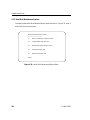
4.2 Freeway Interactive Menu . . . . . . . . . . . . . .
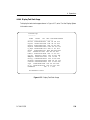
4.3 Shutdown Options . . . . . . . . . . . . . . . . . .
4.3.1 Reboot Server . . . . . . . . . . . . . . . . . . .
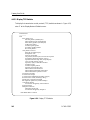
4.4 Display Options . . . . . . . . . . . . . . . . . . . .
4.4.1 Display Log Messages . . . . . . . . . . . . . .
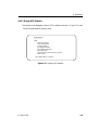
4.4.2 Display Configuration . . . . . . . . . . . . . .
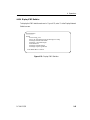
4.4.2.1 Display Physical Configuration . . . . . .
4.4.2.2 Display Service Provider Configuration .
4.4.2.3 Display Boot Parameters. . . . . . . . . .
4.4.3 Display Network Information . . . . . . . . . .
4.4.3.1 Display IP Network Interface Information
4.4.3.2 Display IP Network Hosts . . . . . . . . .
4.4.3.3 Display IP Network Routing Tables . . . .
4.4.3.4 Ping Another IP Host . . . . . . . . . . .
4.4.4 Display System Information . . . . . . . . . . .
4.4.4.1 List I/O Devices . . . . . . . . . . . . . .
4.4.4.2 Display TCB Summary . . . . . . . . . .
4.4.4.3 List Free Memory Blocks . . . . . . . . .
4.4.4.4 Display Task Stack Usage . . . . . . . . .
4.4.4.5 Display Circular Queue of Messages . . .
4.4.5 Display Network Statistics . . . . . . . . . . . .
4.4.5.1 Display TCP Statistics . . . . . . . . . . .
4.4.5.2 Display UDP Statistics . . . . . . . . . . .
DC 900-1333P
.
.
.
.
.
.
.
98
100
108
111
111
112
115
117
.
.
.
.
.
.
.
.
.
.
.
.
.
.
.
.
.
.
.
.
.
.
.
.
.
.
.
.
.
.
.
.
.
.
.
.
.
.
.
.
.
.
.
.
.
.
.
.
.
.
.
.
.
.
.
.
.
.
.
.
.
.
.
.
.
.
.
.
.
.
.
.
.
.
.
.
.
.
.
.
.
.
.
.
.
.
.
.
.
.
.
.
.
.
.
.
.
.
.
.
.
.
.
.
.
.
.
.
.
.
.
.
.
.
.
.
.
.
.
.
.
.
.
.
.
.
.
.
.
.
.
.
.
.
.
.
.
.
.
.
.
.
.
.
.
.
.
.
.
.
.
.
.
.
.
.
.
.
.
.
.
.
.
.
.
.
.
.
.
.
.
.
.
.
.
.
.
.
.
.
.
.
.
.
.
.
.
.
.
.
.
.
.
.
.
.
.
.
.
.
.
.
.
.
.
.
.
.
.
.
.
.
.
.
.
.
.
.
.
.
.
.
.
.
.
.
.
.
.
.
.
.
.
.
.
.
.
.
.
.
.
.
.
.
.
.
.
.
.
.
.
.
.
.
.
.
.
.
.
.
.
.
.
.
.
.
.
.
.
.
.
.
.
.
.
.
.
.
.
.
.
.
.
.
.
.
. 118
. 118
. 119
. 120
. 122
. 122
. 125
. 126
. 126
. 127
. 128
. 129
. 130
. 131
. 132
. 133
. 134
. 135
. 136
. 137
. 138
. 139
. 140
. 141
. 142
. 143
5
Freeway User Guide
4.4.5.3 Display IP Statistics. . . . . . . . . . .
4.4.5.4 Display ICMP Statistics . . . . . . . .
4.4.6 Display User Names. . . . . . . . . . . . . .
4.4.7 Display Current System Time . . . . . . . .
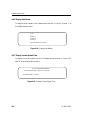
4.5 Modify Configuration . . . . . . . . . . . . . . .
4.5.1 Modify Boot Parameters . . . . . . . . . . .
4.5.2 Modify User Names . . . . . . . . . . . . . .
4.5.3 Modify System Time . . . . . . . . . . . . .
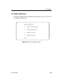
4.6 Trace Functions . . . . . . . . . . . . . . . . . .
4.7 Disk Drive Options . . . . . . . . . . . . . . . .
4.7.1 Hard Disk Copy Options . . . . . . . . . . .
4.7.1.1 Display Hard Disk Directory. . . . . .
4.7.1.2 Display Hard Disk File . . . . . . . . .
4.7.1.3 Copy Boot Server File to Hard Disk . .
4.7.1.4 Copy Hard Disk File to Floppy Disk. .
4.7.1.5 Copy Floppy File to Hard Disk. . . . .
4.7.2 Hard Disk Maintenance Options. . . . . . .
4.7.2.1 Display Hard Disk Directory. . . . . .
4.7.2.2 Build Hard Disk from Boot Server. . .
4.7.2.3 Delete Hard Disk File. . . . . . . . . .
4.7.2.4 Rename Hard Disk File. . . . . . . . .
4.7.3 Floppy Disk Copy Options . . . . . . . . . .
4.7.3.1 Display Floppy Disk Directory. . . . .
4.7.3.2 Display Floppy Disk File . . . . . . . .
4.7.3.3 Copy Boot Server File to Floppy Disk .
4.7.3.4 Copy Floppy Disk File to Hard Disk. .
4.7.3.5 Copy Hard Disk File to Floppy Disk. .
4.7.4 Floppy Disk Maintenance Options. . . . . .
4.7.4.1 Display Floppy Disk Directory. . . . .
4.7.4.2 Delete Floppy Disk File. . . . . . . . .
4.7.4.3 Rename Floppy Disk File. . . . . . . .
4.8 Run VxWorks Shell . . . . . . . . . . . . . . . .
4.9 Example SRA Menu . . . . . . . . . . . . . . . .
4.9.1 Display Loaded Modules . . . . . . . . . . .
4.9.2 Spawn Example SRA task . . . . . . . . . . .
4.10 Logout . . . . . . . . . . . . . . . . . . . . . . .
6
.
.
.
.
.
.
.
.
.
.
.
.
.
.
.
.
.
.
.
.
.
.
.
.
.
.
.
.
.
.
.
.
.
.
.
.
.
.
.
.
.
.
.
.
.
.
.
.
.
.
.
.
.
.
.
.
.
.
.
.
.
.
.
.
.
.
.
.
.
.
.
.
.
.
.
.
.
.
.
.
.
.
.
.
.
.
.
.
.
.
.
.
.
.
.
.
.
.
.
.
.
.
.
.
.
.
.
.
.
.
.
.
.
.
.
.
.
.
.
.
.
.
.
.
.
.
.
.
.
.
.
.
.
.
.
.
.
.
.
.
.
.
.
.
.
.
.
.
.
.
.
.
.
.
.
.
.
.
.
.
.
.
.
.
.
.
.
.
.
.
.
.
.
.
.
.
.
.
.
.
.
.
.
.
.
.
.
.
.
.
.
.
.
.
.
.
.
.
.
.
.
.
.
.
.
.
.
.
.
.
.
.
.
.
.
.
.
.
.
.
.
.
.
.
.
.
.
.
.
.
.
.
.
.
.
.
.
.
.
.
.
.
.
.
.
.
.
.
.
.
.
.
.
.
.
.
.
.
.
.
.
.
.
.
.
.
.
.
.
.
.
.
.
.
.
.
.
.
.
.
.
.
.
.
.
.
.
.
.
.
.
.
.
.
.
.
.
.
.
.
.
.
.
.
.
.
.
.
.
.
.
.
.
.
.
.
.
.
.
.
.
.
.
.
.
.
.
.
.
.
.
.
.
.
.
.
.
.
.
.
.
.
.
.
.
.
.
.
.
.
.
.
.
.
.
.
.
.
.
.
.
.
.
.
.
.
.
.
.
.
.
.
.
.
.
.
.
.
.
.
.
.
.
.
.
.
.
.
.
.
.
.
.
.
.
.
.
.
.
.
.
.
.
.
.
.
.
.
.
.
.
.
.
.
.
.
.
.
.
.
.
.
.
.
.
.
.
.
.
.
.
.
.
.
.
.
.
.
.
.
.
.
.
.
.
.
.
.
.
.
.
.
.
.
.
.
.
.
.
.
.
.
.
.
.
.
.
.
144
145
146
146
147
148
154
155
156
159
160
161
162
163
164
165
166
167
168
177
178
180
181
182
183
184
185
186
187
188
189
190
192
193
193
195
DC 900-1333P
Contents
A
Installation at a Glance
197
A.1 UNIX Installations . . . . . . . . . . . . . . . . . . . . . . . . . . . . . . 198
A.2 VMS Installations . . . . . . . . . . . . . . . . . . . . . . . . . . . . . . . 204
A.3 Windows NT Installations . . . . . . . . . . . . . . . . . . . . . . . . . . 208
B
Freeway Files
B.1
Default Directory Structure. .
B.1.1 Server-resident Software .
B.1.2 ICP-resident Software . .
B.1.3 Client-resident Software .
215
.
.
.
.
.
.
.
.
.
.
.
.
.
.
.
.
.
.
.
.
.
.
.
.
.
.
.
.
.
.
.
.
.
.
.
.
.
.
.
.
.
.
.
.
.
.
.
.
.
.
.
.
.
.
.
.
.
.
.
.
.
.
.
.
.
.
.
.
.
.
.
.
.
.
.
.
.
.
.
.
.
.
.
.
.
.
.
.
.
.
.
.
.
.
.
.
215
215
216
216
Glossary
217
Index
223
DC 900-1333P
7
Freeway User Guide
8
DC 900-1333P
List of Figures
Figure 1–1: Freeway Configuration. . . . . . . . . . . . . . . . . . . . . . . . . . . . . 24
Figure 2–1: Sample UNIX /etc/hosts File . . . . . . . . . . . . . . . . . . . . . . . . . 35
Figure 2–2: Sample Load File for ICP6000 . . . . . . . . . . . . . . . . . . . . . . . . . 48
Figure 2–3: Sample Load File for ICP2432 . . . . . . . . . . . . . . . . . . . . . . . . . 69
Figure 2–4: Sample Load File for ICP2424 . . . . . . . . . . . . . . . . . . . . . . . . . 85
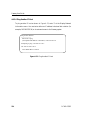
Figure 2–5: Sample Freeway Boot System Main Menu . . . . . . . . . . . . . . . . . . 94
Figure 3–1: Freeway 1100/1150/1200/1300 Boot Configuration File (bootcfg.pci) . . . 101
Figure 3–2: TSI Configuration File (muxcfg) for Server-Resident Software . . . . . . . 113
Figure 4–1: Sample Freeway Interactive Menu. . . . . . . . . . . . . . . . . . . . . . . 120
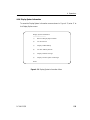
Figure 4–2: Shutdown Options Menu . . . . . . . . . . . . . . . . . . . . . . . . . . . 122
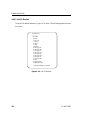
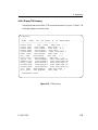
Figure 4–3: Display Options Menu . . . . . . . . . . . . . . . . . . . . . . . . . . . . . 125
Figure 4–4: Display Configuration Menu . . . . . . . . . . . . . . . . . . . . . . . . . 126
Figure 4–5: Display Physical Configuration . . . . . . . . . . . . . . . . . . . . . . . . 127
Figure 4–6: Display Service Provider Configuration. . . . . . . . . . . . . . . . . . . . 128
Figure 4–7: Display System Boot Parameters . . . . . . . . . . . . . . . . . . . . . . . 129
Figure 4–8: Display Network Information Menu . . . . . . . . . . . . . . . . . . . . . 130
Figure 4–9: Display IP Network Interface Information . . . . . . . . . . . . . . . . . . 131
Figure 4–10: Display IP Network Hosts . . . . . . . . . . . . . . . . . . . . . . . . . . . 132
Figure 4–11: Display IP Network Routing Tables . . . . . . . . . . . . . . . . . . . . . . 133
Figure 4–12: Ping Another IP Host . . . . . . . . . . . . . . . . . . . . . . . . . . . . . 134
Figure 4–13: Display System Information Menu . . . . . . . . . . . . . . . . . . . . . . 135
Figure 4–14: List I/O Devices . . . . . . . . . . . . . . . . . . . . . . . . . . . . . . . . 136
Figure 4–15: TCB Summary . . . . . . . . . . . . . . . . . . . . . . . . . . . . . . . . . 137
Figure 4–16: List Free Memory Blocks. . . . . . . . . . . . . . . . . . . . . . . . . . . . 138
Figure 4–17: Display Task Stack Usage . . . . . . . . . . . . . . . . . . . . . . . . . . . 139
DC 900-1333P
9
Freeway User Guide
Figure 4–18: Display Circular Queue of Messages . . . . . . . . . . . . . . . . . . . . . 140
Figure 4–19: Display Network Statistics Menu . . . . . . . . . . . . . . . . . . . . . . 141
Figure 4–20: Display TCP Statistics . . . . . . . . . . . . . . . . . . . . . . . . . . . . 142
Figure 4–21: Display UDP Statistics . . . . . . . . . . . . . . . . . . . . . . . . . . . . 143
Figure 4–22: Display IP Statistics . . . . . . . . . . . . . . . . . . . . . . . . . . . . . . 144
Figure 4–23: Display ICMP Statistics. . . . . . . . . . . . . . . . . . . . . . . . . . . . 145
Figure 4–24: Display User Names . . . . . . . . . . . . . . . . . . . . . . . . . . . . . 146
Figure 4–25: Display Current System Time . . . . . . . . . . . . . . . . . . . . . . . . 146
Figure 4–26: Modify Configuration Menu . . . . . . . . . . . . . . . . . . . . . . . . . 147
Figure 4–27: Modify Boot Parameters . . . . . . . . . . . . . . . . . . . . . . . . . . . 149
Figure 4–28: Modify User Names. . . . . . . . . . . . . . . . . . . . . . . . . . . . . . 154
Figure 4–29: Modify System Time . . . . . . . . . . . . . . . . . . . . . . . . . . . . . 155
Figure 4–30: File Transfer Protocol Example . . . . . . . . . . . . . . . . . . . . . . . 157
Figure 4–31: Trace Functions Menu . . . . . . . . . . . . . . . . . . . . . . . . . . . . 158
Figure 4–32: Disk Drive Options Menu . . . . . . . . . . . . . . . . . . . . . . . . . . 159
Figure 4–33: Hard Disk Copy Options Menu . . . . . . . . . . . . . . . . . . . . . . . 160
Figure 4–34: Display Hard Disk Directory . . . . . . . . . . . . . . . . . . . . . . . . . 161
Figure 4–35: Display Hard Disk File . . . . . . . . . . . . . . . . . . . . . . . . . . . . 162
Figure 4–36: Copy Boot Server File to Hard Disk . . . . . . . . . . . . . . . . . . . . . 163
Figure 4–37: Copy Hard Disk File to Floppy Disk . . . . . . . . . . . . . . . . . . . . . 164
Figure 4–38: Copy Floppy File to Hard Disk . . . . . . . . . . . . . . . . . . . . . . . . 165
Figure 4–39: Hard Disk Maintenance Options Menu . . . . . . . . . . . . . . . . . . . 166
Figure 4–40: Display Hard Disk Directory . . . . . . . . . . . . . . . . . . . . . . . . . 167
Figure 4–41: Boot Parameters Modified to Boot from Boot Server. . . . . . . . . . . . 171
Figure 4–42: Boot Parameters Modified to Boot from Hard Disk . . . . . . . . . . . . 175
Figure 4–43: Delete Hard Disk File . . . . . . . . . . . . . . . . . . . . . . . . . . . . . 177
Figure 4–44: Rename Hard Disk File . . . . . . . . . . . . . . . . . . . . . . . . . . . . 179
Figure 4–45: Floppy Disk Copy Options Menu . . . . . . . . . . . . . . . . . . . . . . 180
Figure 4–46: Display Floppy Disk Directory . . . . . . . . . . . . . . . . . . . . . . . . 181
Figure 4–47: Display Floppy Disk File . . . . . . . . . . . . . . . . . . . . . . . . . . . 182
Figure 4–48: Copy Boot Server File to Floppy Disk . . . . . . . . . . . . . . . . . . . . 183
Figure 4–49: Copy Floppy Disk File to Hard Disk . . . . . . . . . . . . . . . . . . . . . 184
10
DC 900-1333P
List of Figures
Figure 4–50: Copy Hard Disk File to Floppy Disk . . . . . . . . . . . . . . . . . . . . . 185
Figure 4–51: Floppy Disk Maintenance Options Menu. . . . . . . . . . . . . . . . . . . 186
Figure 4–52: Display Floppy Disk Directory . . . . . . . . . . . . . . . . . . . . . . . . 187
Figure 4–53: Delete Floppy Disk File . . . . . . . . . . . . . . . . . . . . . . . . . . . . 188
Figure 4–54: Rename Floppy Disk File . . . . . . . . . . . . . . . . . . . . . . . . . . . 189
Figure 4–55: VxWorks Shell Display . . . . . . . . . . . . . . . . . . . . . . . . . . . . . 191
Figure 4–56: Trace Functions Menu . . . . . . . . . . . . . . . . . . . . . . . . . . . . . 192
Figure 4–57: Display Loaded Modules. . . . . . . . . . . . . . . . . . . . . . . . . . . . 193
Figure 4–58: Example SRA Task Display . . . . . . . . . . . . . . . . . . . . . . . . . . 194
DC 900-1333P
11
Freeway User Guide
12
DC 900-1333P
List of Tables
Table 2–1:
Summary of Software Installation Steps . . . . . . . . . . . . . . . . . . . . 30
Table 2–2:
Protocol Identifiers . . . . . . . . . . . . . . . . . . . . . . . . . . . . . . . 31
Table 2–3:
Client TSI Configuration Files (UNIX) . . . . . . . . . . . . . . . . . . . . 54
Table 2–4:
Client DLI Configuration Files (UNIX) . . . . . . . . . . . . . . . . . . . . 55
Table 2–5:
Client TSI Configuration Files (UNIX) . . . . . . . . . . . . . . . . . . . . 72
Table 2–6:
Client DLI Configuration Files (VMS) . . . . . . . . . . . . . . . . . . . . 73
Table 2–7:
Client TSI Configuration Files (Windows NT) . . . . . . . . . . . . . . . . 91
Table 2–8:
Client DLI Configuration Files (Windows NT) . . . . . . . . . . . . . . . . 92
Table 4–1:
Freeway System Boot Parameter Descriptions. . . . . . . . . . . . . . . . . 150
Table 4–2:
Flags for Reset Action. . . . . . . . . . . . . . . . . . . . . . . . . . . . . . 153
Table 4–3:
Summary of Steps Required to Build a Hard Disk . . . . . . . . . . . . . . 168
DC 900-1333P
13
Freeway User Guide
14
DC 900-1333P
Preface
Purpose of Document
This document describes how to install and operate software on Protogate’s Freeway
server.
Note
The information in this document refers to the Freeway models
from Protogate and Simpact that use the VxWorks operating system. As of this document revision (Feb 2002), these Freeway models have been replaced with newer hardware models. The
specifications of the newer hardware will be reflected in a later edition of this document. Go to Protogate’s web page (www.protogate.com) for more information.
Intended Audience
This document should be read by users who install and operate the Freeway series of
servers. The Freeway server has many utilities that allow you to configure and control
the run-time operation of the server.
Required Equipment
Items Supplied by Protogate
•
Freeway unit
DC 900-1333P
15
Freeway User Guide
•
Power cord (Freeway 1300 and 8800 have two power cords)
•
Set of keys (for hinged front panel on Freeway 1100/1150/1200/1300)
•
Console cable (each end of the cable has both a 9-pin and a 25-pin connector)
(Freeway 1100/1150/1200/1300)
•
Cable with a 9-pin and a 25-pin connector on each end (Freeway 2000/4000/8800
with an MVME 2600 CPU board)
•
Appropriate serial cables to connect the ICPs to the data communications equipment (Freeway 1100/1150/1200/1300)
•
Boot parameter initialization disk (Freeway 1100/1150/1200/1300)
•
SCSI II-style high-density termination connector (Freeway 2000/4000, unless you
have purchased a Freeway 2000/4000 with a CPU 8)
•
Anti-static strap
•
Two-headed loopback cable(s), one per Freeway ICP (Freeway 1100/1150/
1200/1300)
•
Three-headed loopback cable(s), one per Freeway ICP (all Freeways)
•
Software distribution media
•
Various documentation
Items Supplied by You
16
•
Standard Ethernet or Fast Ethernet local-area network
•
Computer running TCP/IP and FTP or RSH to be used as a boot server
•
VT100-compatible terminal or terminal emulator to be used as the Freeway local
console, plus a standard null modem EIA-232, 25-pin cable for connecting it to
Freeway. (The Freeway 1100, 1150, 1200, or 1300 server can be booted using a
local console or by using the boot parameters initialization disk.)
DC 900-1333P
Preface
•
Cables for connecting Freeway to the LAN and WAN
•
Synchronous modem for loopback testing
Organization of Document
Chapter 1 gives an overview of the Freeway server.
Chapter 2 describes the Freeway software installation procedures.
Chapter 3 describes how to customize the system configuration.
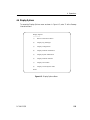
Chapter 4 describes the Freeway menus used in basic operation.
Appendix A gives a quick summary of the installation procedures that were described in
detail in Chapter 2 and instructions for building a client application.
Appendix B gives an overview of the files that make up the Freeway software.
The Glossary lists Freeway terminology and acronyms.
11/16/99
Leslie: Add
1567 to the
“Specials”
table.
Protogate References
The following general product documentation list is to familiarize you with the available Protogate Freeway and embedded ICP products. The applicable product-specific
reference documents are mentioned throughout each document (also refer to the
“readme” file shipped with each product). Most documents are available on-line at Protogate’s web site, www.protogate.com.
General Product Overviews
•
•
•
•
Freeway 1100 Technical Overview
25-000-0419
Freeway 2000/4000/8800 Technical Overview
25-000-0374
ICP2432 Technical Overview
25-000-0420
ICP6000X Technical Overview
25-000-0522
DC 900-1333P
17
Freeway User Guide
Hardware Support
•
•
•
•
•
•
•
•
•
•
•
Freeway 500 Hardware Installation Guide
DC-900-2000
Freeway 1100/1150 Hardware Installation Guide
DC-900-1370
Freeway 1200/1300 Hardware Installation Guide
DC-900-1537
Freeway 2000/4000 Hardware Installation Guide
DC-900-1331
Freeway 3100 Hardware Installation Guide
DC-900-2002
Freeway 3200 Hardware Installation Guide
DC-900-2003
Freeway 3400 Hardware Installation Guide
DC-900-2004
Freeway 3600 Hardware Installation Guide
DC-900-2005
Freeway 8800 Hardware Installation Guide
DC-900-1553
Freeway ICP6000R/ICP6000X Hardware Description
DC-900-1020
ICP6000(X)/ICP9000(X) Hardware Description and Theory of
Operation
DC-900-0408
•
•
•
•
ICP2424 Hardware Description and Theory of Operation
DC-900-1328
ICP2432 Hardware Description and Theory of Operation
DC-900-1501
ICP2432 Electrical Interfaces (Addendum to DC-900-1501)
DC-900-1566
ICP2432 Hardware Installation Guide
DC-900-1502
Freeway Software Installation and Configuration Support
•
•
•
•
Freeway Message Switch User Guide
DC-900-1588
Freeway Release Addendum: Client Platforms
DC-900-1555
Freeway User Guide
DC-900-1333
Freeway Loopback Test Procedures
DC-900-1533
Embedded ICP Software Installation and Programming Support
•
•
•
•
•
•
18
ICP2432 User Guide for Digital UNIX
DC-900-1513
ICP2432 User Guide for OpenVMS Alpha
DC-900-1511
ICP2432 User Guide for OpenVMS Alpha (DLITE Interface)
DC-900-1516
ICP2432 User Guide for Solaris STREAMS
DC-900-1512
ICP2432 User Guide for Windows NT
DC-900-1510
ICP2432 User Guide for Windows NT (DLITE Interface)
DC-900-1514
DC 900-1333P
Preface
Application Program Interface (API) Programming Support
•
•
•
Freeway Data Link Interface Reference Guide
DC-900-1385
Freeway Transport Subsystem Interface Reference Guide
DC-900-1386
QIO/SQIO API Reference Guide
DC-900-1355
Socket Interface Programming Support
•
Freeway Client-Server Interface Control Document
DC-900-1303
Toolkit Programming Support
•
Freeway Server-Resident Application and Server Toolkit
Programmer Guide
DC-900-1325
•
•
OS/Impact Programmer Guide
DC-900-1030
Protocol Software Toolkit Programmer Guide
DC-900-1338
Protocol Support
•
•
•
•
•
•
•
•
•
•
•
•
•
•
•
ADCCP NRM Programmer Guide
DC-900-1317
Asynchronous Wire Service (AWS) Programmer Guide
DC-900-1324
AUTODIN Programmer Guide
DC-908-1558
Bit-Stream Protocol Programmer Guide
DC-900-1574
BSC Programmer Guide
DC-900-1340
BSCDEMO User Guide
DC-900-1349
BSCTRAN Programmer Guide
DC-900-1406
DDCMP Programmer Guide
DC-900-1343
FMP Programmer Guide
DC-900-1339
Military/Government Protocols Programmer Guide
DC-900-1602
N/SP-STD-1200B Programmer Guide
DC-908-1359
SIO STD-1300 Programmer Guide
DC-908-1559
X.25 Call Service API Guide
DC-900-1392
X.25/HDLC Configuration Guide
DC-900-1345
X.25 Low-Level Interface
DC-900-1307
DC 900-1333P
19
Freeway User Guide
Document Conventions
The term “Freeway” refers to any of the Freeway models (for example, 1100, 1150, 1200,
1300, 2000, 4000, or 8800).
A Freeway with an MVME 162 CPU board is a 68K-based Freeway 2000/4000/8800 with
5/24/99 Ginni:
Eric says to
leave CPU 7 in
this list in case
a customer
with an older
Freeway gets
this manual.
a CPU 7, 8, 9, or 10 based on the Motorola MVME 162 single-board computer. The
handle of the CPU board is labelled “MVME 162.”
A Freeway with an MVME 2600 CPU board is a Power PC-based Freeway
2000/4000/8800 with a CPU 11, 12, or 14 based on the Motorola MVME 2600 single-board computer. The handle of the CPU board is labelled “MVME 2600.”
Program code samples are written in the “C” programming language.
Earlier Freeway terminology used the term “synchronous” for blocking I/O and “asynchronous” for non-blocking I/O. Some parameter names reflect the previous terminology.
Revision History
The revision history of the Freeway User Guide, Protogate document DC 900-1333P, is
recorded below:
Revision
20
Release Date
Description
DC 900-1333A
May 1994
Original release
DC 900-1333B
September 1994
Added Freeway 1000 information
Updated installation procedures
Updated operation procedures
DC 900-1333C
November 1994
Updated installation procedures
DC 900-1333D
February 1995
Updated installation procedures
DC 900-1333E
March 1995
Added more detailed Freeway 1000 information
DC 900-1333F
May 1995
Enhanced boot parameters information, updated
menus, and added loopback information for AWS and
ADCCP NRM
DC 900-1333P
Preface
Revision
Release Date
Description
DC 900-1333G
March 1996
Updated for version 2.4 release
Removed bootp information
Clarified server toolkit information
Replaced X.25 loopback test with CS API test
Added information on:
• DDCMP
• ICP6030
• Marketfeed 2000
• TACMIL
• Windows NT
DC 900-1333H
May 1997
Updated for version 2.7 server release
Added Freeway 8800 information
DC 900-1333I
August 1997
Updated for version 2.7.1 server release;
user must now build binary and library files
Deleted Freeway 1000 information
Added Freeway 1100 information
DC 900-1333J
June 1998
Updated for version 2.8 server release
Moved loopback tests to separate document
DC 900-1333K
December 1998
Updated for server toolkit release
DC 900-1333L
February 1999
Updated for ICP_IP virtual devices
Added Freeway 1150 information
Moved port numbering and cabling and LED appendices to hardware documents
DC 900-1333M June 1999
Updated for version 2.9 server release
Updated menu options
Added send and receive buffer size options to the
bootcfg.ip file
Added Freeway 1200 and 1300 information
DC 900-1333N
July 1999
Added SNMP information (Section 1.2.4 on page 27,
Figure 4–15 on page 137, and Figure 4–17 on page 139)
DC 900-1333O
December 1999
Added new boot flag, 0x2000
Added snd_q_size, connect_period, linger_on, and
linger_off configuration parameters to Section 3.2.1
Added sock_stream_listen and sock_stream_ connect to
socket type parameter
DC 900-1333P
February 2002
Update document with Protogate contact information.
DC 900-1333P
21
Freeway User Guide
Customer Support
If you are having trouble with any Protogate product, call us at (858) 451-0865 Monday
through Friday between 8 a.m. and 5 p.m. Pacific time.
You can also fax your questions to us at (877) 473-0190 any time. Please include a cover
sheet addressed to “Customer Service.”
We are always interested in suggestions for improving our products. You can use the
report form in the back of this manual to send us your recommendations.
22
DC 900-1333P
Chapter
1
Freeway Introduction
This manual describes how to install and operate software on your Freeway server.
Before installing the server software, you should familiarize yourself with basic Freeway
concepts as described in this introductory chapter. Then you can proceed to Chapter 2
which contains the software installation procedures. Refer to the Glossary for Freeway
terminology and acronyms.
1.1 Freeway Overview
02/23/99
Ginni: I took
today’s
version of the
overview, but
modified it
here to be
server only.
Protogate provides a variety of wide-area network (WAN) connectivity solutions for
real-time financial, defense, telecommunications, and process-control applications.
Protogate’s Freeway server offers flexibility and ease of programming using a variety of
LAN-based server hardware platforms.
Protogate’s Freeway communications servers enable client applications on a local-area
network (LAN) to access specialized WANs through the DLI. The Freeway server can be
any of several models (for example, Freeway 1100/1150, Freeway 1200/1300, Freeway
2000/4000, or Freeway 8000/8800). The Freeway server is user programmable and communicates in real time. It provides multiple data links and a variety of network services
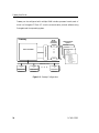
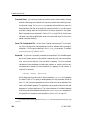
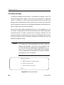
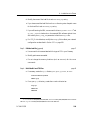
to LAN-based clients. Figure 1–1 shows the Freeway configuration.
To maintain high data throughput, Freeway uses a multi-processor architecture to support the LAN and WAN services. The LAN interface is managed by a single-board computer, called the server processor. It uses the commercially available VxWorks operating
system to provide a full-featured base for the LAN interface and layered services needed
by Freeway.
DC 900-1333P
23
Freeway User Guide
Freeway can be configured with multiple WAN interface processor boards, each of
which is a Protogate ICP. Each ICP runs the communication protocol software using
Protogate’s real-time operating system.
AAAAAAAA
AAAAAAAA
AAAAAAAA
AAAAAAAA
AAAAAAAA
AAAAAAAA
AAAAAAAA
AAAAAAAA
AAAAAAAA
Industry Standard Bus
AA
AA
AA
AA
AA
AA
AA
AA
Server Processor
WAN
Interface
Processors
WAN Protocol
Options
SCADA
ICP
Defense
Commercial
X.25
Bisync
HDLC . . .
● ● ●
Freeway
Financial
SWIFT
CHIPS
Telerate
Telekurs
Reuters
40+ Market
Feeds . . .
ICP
Ethernet LAN
Freeway
API
Application
Application
Application
Client 1
Client 2
Client n
●
●
●
3413
Freeway
API
Freeway
API
Figure 1–1: Freeway Configuration
24
DC 900-1333P
1: Freeway Introduction
Summary of product features:
•
Provision of WAN connectivity either through a LAN-based Freeway server or
directly using an embedded ICP
•
Elimination of difficult LAN and WAN programming and systems integration by
providing a powerful and consistent data link interface
•
Variety of off-the-shelf communication protocols available from Protogate which
are independent of the client operating system and hardware platform
•
Support for multiple WAN communication protocols simultaneously
•
Support for multiple ICPs (two, four, eight, or sixteen communication lines per
ICP)
•
Wide selection of electrical interfaces including EIA-232, EIA-449, EIA-530, and
V.35
•
Creation of customized server-resident and ICP-resident software, using Protogate’s software development toolkits
•
Freeway server standard support for Ethernet and Fast Ethernet LANs running
the transmission control protocol/internet protocol (TCP/IP)
•
Freeway server standard support for FDDI LANs running the transmission control protocol/ internet protocol (TCP/IP)
•
Freeway server management and performance monitoring with the simple network management protocol (SNMP), as well as interactive menus available
through a local console, telnet, or rlogin
DC 900-1333P
25
Freeway User Guide
1.2 Freeway Concepts
Decreased size
of body
paragraphs
and headings
to get last
sentence on
this page.
The following concepts support the Freeway features described in Section 1.1.
1.2.1 Freeway Services
Freeway can be configured to offer a number of services to clients residing on the LAN.
These services are shared among applications designed to operate in the client/server
model of today’s distributed computing environment.
Freeway offers Protogate’s real-time data communication protocols. These services
allow clients to connect to primary and consolidated financial feeds, military satellite
communications, process control monitoring, telecommunications network monitoring, and similar applications.
1.2.2 User Customization
If one of the standard services offered by Freeway does not meet the requirements of
your application, you can develop and integrate customized services into Freeway using
Protogate’s software development kits. The Protocol Software Toolkit Programmer Guide
explains how to develop real-time protocols that run on an ICP residing within
Freeway. The Freeway Server-Resident Application and Server Toolkit Programmer Guide
explains how to develop server-resident applications.
1.2.3 Server Management
Server Management is supported through an interactive menu interface that can be
accessed either through a local console serial port, or via remote login using telnet or
rlogin facilities. Functions such as physical and service configuration, monitoring of
server operation, system shutdown, and system startup are described in Chapter 4.
26
DC 900-1333P
1: Freeway Introduction
1.2.4 SNMP Support
Freeway software provides an SNMP v1/v2c-compliant SNMP agent that supports
read-only SNMP access to Freeway-supported MIBs. Freeway provides SNMP support
for the MIBs listed below, regardless of which ICP-resident protocol service is used.
•
Protogate enterprise MIB for Freeway
•
RFC-1213 (MIB-II) support for LAN interfaces
Selected ICP-resident protocol services provide additional SNMP support for read-only
access to the MIBs listed below.
•
RFC-1213 (MIB-II) interfaces group for WAN ports on the ICP
•
RFC-1659 (rs232-like-devices) for WAN ports on the ICP
The Protogate enterprise MIB for Freeway is published with the Freeway software as the
freeway/include/freeway.mib file. The RFC-1213 and RFC-1659 MIB definitions may be
obtained via the Internet without charge.
DC 900-1333P
27
Freeway User Guide
28
DC 900-1333P
Chapter
2
Software Installation
This chapter describes how to install the Freeway server/client, protocol, and toolkit
software. You must have installed the Freeway hardware as described in the appropriate
Freeway hardware installation guide.
Note
After you have followed the detailed software installation procedures outlined in this chapter, you can refer to the “Installation at
a Glance” summary in Appendix A as a quick reference for future
installations.
After you finish these procedures, familiarize yourself with Freeway operations as
described in Chapter 4. You might also want to review Appendix B which gives an overview of the files that make up the Freeway software.
Note
If you are installing more than one protocol, it is best to perform
the software installation and loopback verification testing for one
protocol before attempting to customize your Freeway system for
multiple protocols (described in Chapter 3).
DC 900-1333P
29
Freeway User Guide
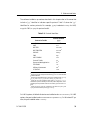
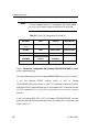
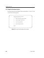
Table 2–1 summarizes the software installation steps.
Table 2–1: Summary of Software Installation Steps
Steps
Reference Section(s)
1.
Select a UNIX, VMS, or Windows NT computer on the
same LAN as Freeway that supports TCP/IP and the file
transfer protocol (FTP) or, for UNIX or Windows NT,
remote shell (RSH). You will use this computer for
Freeway software installation and also configure it as
the Freeway boot server.
2.
Configure the computer to act as a boot server.
3.
Load the Freeway software from the distribution media Section 2.2 on page 37 for UNIX
onto the boot server you selected in Step 11.
Section 2.3 on page 57 for VMS
Section 2.4 on page 75 for Windows NT
4.
Modify the boot and load files.
Section 2.2.3 on page 45 for UNIX
Section 2.3.3 on page 66 for VMS
Section 2.4.3 on page 82 for Windows NT
5.
Build the DLI and TSI files.
Section 2.2.4 on page 48 for UNIX
Section 2.3.4 on page 69 for VMS
Section 2.4.4 on page 84 for Windows NT
6.
For X.25 only, build the CS API library file.
Section 2.2.5 on page 49 for UNIX
Section 2.3.5 on page 70 for VMS
Section 2.4.5 on page 86 for Windows NT
7.
Compile the example server-resident application Section 2.2.6 on page 50 for UNIX
(UNIX and Windows NT).
Section 2.4.6 on page 87 for Windows NT
8.
Compile the Server Toolkit (UNIX and Windows NT). Section 2.2.7 on page 52 for UNIX
Section 2.4.7 on page 89 for Windows NT
9.
Build the QIO/SQIO API library file (VMS only).
Section 2.1 on page 32
Section 2.3.6 on page 71 for VMS
10. Build the loopback test(s) using the appropriate make Section 2.2.8 on page 53 for UNIX
file.
Section 2.3.7 on page 71 for VMS
Section 2.4.8 on page 90 for Windows NT
11. Modify the Freeway System Boot Parameters.
Section 2.5 on page 93
12. Boot Freeway.
Section 2.6 on page 94
13. Run the loopback test.
Freeway Loopback Test Procedures manual
1 Installing
30
new software overwrites the previous software.
DC 900-1333P
2: Software Installation
The software installation procedures described in this chapter refer to file names that
include a “ppp” identifier to indicate a specific protocol. Table 2–2 shows the “ppp”
identifiers for various protocols. For example, pppalp translates to awsalp for AWS,
fmpalp for FMP, or spsalp for protocol toolkit.
Table 2–2: Protocol Identifiers
Protocol or Toolkit
Protocol Identifier
(ppp)
AUTODIN
autodin1
AWS
aws
BSC3270
bsc32702
BSC2780/3780
bsc3780a
DDCMP
ddcmp
FMP
fmp
ADCCP NRM
nrm
Protocol Toolkit
sps
Server-resident Application
sra3
STD1200B
s12
Military/Government
mil4
X.25/HDLC
x255
1
Except for the readme and release notes, where ppp is adn.
for the load configuration files where ppp is bsc for both BSC3270
and BSC2780/3780.
3 Except for the executable object for the protocol software where ppp is sps
(sps_fw_2424.mem, sps_fw_2432.mem, and sps_fw_6000.mem).
4
Except for the load configuration files where ppp is milxxxyyy (xxxyyy
identifies the particular Military/Government product designation, distinguished by the unique subset of the full set of military protocols that it contains).
5
Except for the DLI and TSI configuration files which are apidcfg and
apitcfg and the test directory where ppp is x25mgr.
2 Except
7/23: SAVE
THIS
MARGINPAR
Ron Tabor says
it’s okay to say
the default
directories for
NT are
installed under
C:\freeway;
even for 4.0,
they’re installed
there but the
On UNIX systems, all default directories are installed under /usr/local/freeway. On VMS user has to use
an alias in the
systems, they are installed under SYS$SYSDEVICE:[FREEWAY]. On Windows NT sys- path name to
reach a file.
tems, they are installed under C:\freeway.
DC 900-1333P
31
Freeway User Guide
2.1 Configure the Boot Server
Before you can boot Freeway, the boot server and Freeway must be configured to communicate with each other. Multiple Freeway servers can be configured to boot from the
same boot server. The following steps are required:
1. Create a file transfer protocol (FTP) or remote shell (RSH) user account on the
boot server (Section 2.1.2); as shipped, the boot parameters are set to boot the
system using FTP.
2. Define the system names and Internet addresses for Freeway, the boot server, and
the gateway processor (if applicable) on the boot server (Section 2.1.3).
Your system administrator might have already completed these steps during the hardware installation procedures described in the hardware installation guide for your
Freeway. If so, skip this section and proceed with Section 2.2 on page 37 for UNIX,
Section 2.3 on page 57 for VMS, or Section 2.4 on page 75 for Windows NT.
During the boot process Freeway is considered a client while it downloads files over the
Ethernet from the Freeway boot directory located on the boot server. After the boot process completes, Freeway starts its normal role as a communications server for its clients.
Section 4.3.1 on page 122 describes the boot process.
Freeway supports the FTP or RSH configuration in the boot process (Section 2.1.1
through Section 2.1.3).
32
DC 900-1333P
2: Software Installation
2.1.1 Configure FTP or RSH
The boot server must support the file transfer protocol (FTP) or remote shell (RSH).
RSH is available on UNIX and Windows NT systems, but not on VMS systems.
Freeway uses FTP or RSH to request each of its download files from the boot server. To
respond to the download requests, the boot server must also have the FTP or RSH
daemon process running.
On UNIX systems, the /etc/inetd.conf command file usually starts the FTP or RSH daemon process. Refer to your UNIX user manuals for details.
On VMS systems, if you don’t already have a TCP/IP package that supports FTP, you
must install one. Refer to the user manuals for the software you are using to find out
how to configure the FTP daemon process.
On Windows NT systems, refer to your Windows NT administration manuals for
details on how to start the FTP or RSH server.
2.1.2 Create the FTP or RSH User Account on the Boot Server
Using FTP or RSH for downloading requires Freeway to log in to the boot server. By
default, Freeway logs in with the FTP user name of freeway and an FTP password of
password. Create an FTP user account on the boot server to match these values. This
account, freeway, must have read/write/execute access to all installed files in the directories and subdirectories below freeway. For instructions on how to create user accounts,
refer to your system administrator’s guide or consult your system administrator.
If you prefer to use RSH on your UNIX or Windows NT system, you must still set up a
user account, but the password is not used for accessing the boot server through its
remote shell daemon.
DC 900-1333P
33
Freeway User Guide
In UNIX systems, the files to which Freeway requires access are in the default
/usr/local/freeway directory which is created during the installation procedure described
in Section 2.2.2.
In VMS systems, the files to which Freeway requires access are in the default
7/23: SAVE
THIS
MARGINPAR
Ron Tabor says
it’s okay to say
the default
directories for
NT are
installed under
C:\freeway;
even for 4.0,
they’re installed
there but the
user has to use
an alias in the
path name to
reach the file.
SYS$SYSDEVICE:[FREEWAY] directory which is created during the installation proce-
dure described in Section 2.3.2.
In Windows NT systems, the files to which Freeway requires access are in the default
C:\freeway directory which is created during the installation procedure described in
Section 2.4.2
You can change the default FTP user name and FTP password that Freeway uses by
changing the corresponding boot parameters on the Freeway system as described in
Section 4.5.1 on page 148. If you do, remember that you must also change the user
name and password of the FTP account on the boot server.
2.1.3 Define Freeway to the Boot Server
In this section you will define Freeway’s Internet protocol address (henceforth called the
Internet address) and system name to the boot server. The boot server needs this information so it can communicate with Freeway. You will need this information to configure the Freeway boot parameters.
If your boot server is running VMS, configuring Internet addresses depends on the
TCP/IP package installed on your computer. Consult your TCP/IP documentation for
instructions on how to define system names and Internet addresses for your VMS computer.
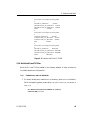
If you have a UNIX or Windows NT boot server, use the following procedure:
Step 1:
For UNIX systems, the Internet addresses and system names of computers on
the network are maintained in the /etc/hosts file.
34
DC 900-1333P
2: Software Installation
For Windows NT systems, the Internet addresses and system names of computers on
the network are maintained in the hosts or lmhosts file.
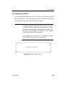
If your network is managed by a domain name server, the hosts file should not be edited
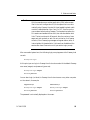
locally, as it is maintained and distributed by the domain name server. If you are not
using a domain name server, this file can be edited on the boot server. In the hosts file,
find the Internet address and system name of the computer you have selected as your
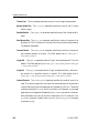
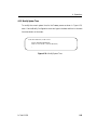
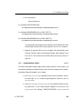
boot server. Figure 2–1 shows a sample UNIX /etc/hosts file in which the boot server has
an Internet address of 192.168.45.1 and a system name of bootmaster.
# This is the master Internet address file for XYZ Corporation.
# If you need an address, check here first to make sure it is not
# being used. If it is not, add the address, the system name for the
# device, and the owner. You can then export this file to your device
# if it is appropriate.
#
#
# *************************************************************
#
TCP HOST TABLE
# *************************************************************
#
# 127.0.0.1
loopback --- do not remove.
#
127.0.0.1
localhost
#
#
#
192.168.45.1
bootmaster
# Boot server for Freeway systems
192.168.45.2
accnt
# accounting
192.168.45.3
sales
# sales
192.168.45.4
mktg
# marketing
192.168.45.5
prod
# production
192.168.45.6
freeway1
# Freeway system 1
192.168.45.7
freeway2
# Freeway system 2
Figure 2–1: Sample UNIX /etc/hosts File
DC 900-1333P
35
Freeway User Guide
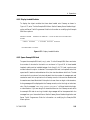
Step 2:
Select a system name and Internet address for the Freeway server and enter
them on a line in the hosts files of the Freeway boot server and any LAN network device
that will be communicating with Freeway. If you have more than one Freeway server,
enter one line for each server. In the sample hosts file in Figure 2–1, two Freeway servers
have been defined. The first has an Internet address of 192.168.45.6 and a system name
of freeway1. The second has an Internet address of 192.168.45.7 and a system name of
freeway2.
If your Freeway server has multiple LAN interface boards (for example, dual Ethernet),
enter a line for each board in the hosts file of any LAN network device that will be communicating with that board. Although this step is required only if you wish to assign a
logical name to each LAN interface, it is recommended to ensure that the Internet
address of each board is reserved for its exclusive use. No two LAN interface boards
within a Freeway may be configured to operate on the same sub-network.
Step 3:
Write down the Internet address and system name for both Freeway and the
boot server.
36
DC 900-1333P
2: Software Installation
2.2 Install the Freeway Software onto a UNIX Computer
This section describes how to install the Freeway software from the distribution media
onto a UNIX computer. Later in these procedures you will use this computer as a boot
server to boot Freeway.
Note
After you have followed the detailed software installation procedures outlined in this chapter, you can refer to the “Installation at
a Glance” summary in Appendix A as a quick reference for future
installations.
2.2.1 Contents of the UNIX Distribution Media
Freeway software for UNIX computers is distributed on the following types of media in
tar or cpio format. The label on the media identifies the format used.
•
Quarter-inch cartridge
•
Quarter-inch datastream
•
TK50 cartridge
•
4mm tape
•
8mm tape
•
CD-ROM
DC 900-1333P
37
Freeway User Guide
2.2.1.1 Server/Client Software
The server/client distribution media is labeled Freeway Server Software.
The following files are in the freeway directory:
•
readme.ser provides general information about the server software
•
relnotes.ser provides specific information about the current release of the server
software
•
env486, env68k, envcom, and envppc are environment definition files for the exam-
ple server-resident application (SRA)
•
MakeSRA.I486, MakeSRA.68K, and MakeSRA.ppc are make files for the example
SRA
The following general files are in the freeway/boot directory:
•
bootcfg.ip is an example boot configuration file for ICP_IP virtual devices
•
bootcfg.isa is the boot configuration file for a Freeway 1100 with ICP2424s (ISA-
bus boards)
•
bootcfg.pci is the boot configuration file for a Freeway 1100 with ICP2432s (PCI
boards) and Freeway 1150/1200/1300
•
bootcfg.vme is the boot configuration file for Freeway 2000/4000/8800
•
fw486 is the system boot file for Freeway 1100/1150/1200/1300
•
fw162 is the standard system boot file for a Freeway 2000/4000/8800 with an
MVME 162 CPU 9 or CPU 10
•
fw162l is the limited memory system boot file for a Freeway 2000/4000/8800 with
an MVME 162 CPU 7 or CPU 8
38
DC 900-1333P
2: Software Installation
•
fw2604 is the system boot file for a Freeway 2000/4000/8800 with an MVME 2600
CPU
•
fw486.sym is the symbol table for the Freeway 1100/1150/1200/1300 boot image
•
fw162.sym is the standard symbol table for the boot image of a Freeway
2000/4000/8800 with an MVME 162 CPU 9 or CPU 10
•
fw162l.sym is the limited memory symbol table for the boot image of a Freeway
2000/4000/8800 with an MVME 162 CPU 7 or CPU 8
•
fw2604.sym is the symbol table for the boot image of a Freeway 2000/4000/8800
with an MVME 2600 CPU
•
muxcfg1 is the server TSI configuration file
•
xio_2424.mem, xio_2432.mem, or xio_6000.mem2 are the executable objects for the
system-services module
The following files specific to the server-resident application (SRA) are also in the freeway/boot directory:
•
buffer.size is the buffer size file for the protocol toolkit used with the example SRA
•
ftstdcfg , ftsttcfg, sradcfg , and sratcfg are the data link interface (DLI) and transport
subsystem interface (TSI) configuration files for the example SRA
•
fw486d is the debug version of the system boot file for Freeway 1100/1150/
1200/1300
1. The example server-resident application uses muxcfg.sra. The Military/Government protocol uses
milmuxcfg.
2. Freeway server release G (and later) installs the XIO image files in the freeway/boot directory. Prior
to June 1, 1998, the XIO image files were distributed in the freeway/icpcode/icpxxxx/osimpact directory. As a
result, the load files provided with protocols with a release date prior to June 1, 1998 contain a fully qualified path for the protocol and XIO image files. Such files should be modified to remove the path to the XIO
image. This allows Freeway to boot the local copy of the XIO image provided in the freeway/boot directory
with the current Freeway server release.
DC 900-1333P
39
Freeway User Guide
•
fw162d is the debug version of the standard system boot file for a Freeway
2000/4000/8800 with an MVME 162 CPU 9 or CPU 10
•
fw2604d is the debug version of the system boot file for a Freeway 2000/4000/8800
with an MVME 2600 CPU
•
fw486d.sym is the symbol table for the Freeway 1100/1150/1200/1300 debug
server image
•
fw162d.sym is the standard symbol table for the debug server image of a Freeway
2000/4000/8800 with an MVME 162 CPU 9 or CPU 10
•
fw2604d.sym is the symbol table for the debug server image of a Freeway
2000/4000/8800 with an MVME 2600 CPU
•
sps_fw_2424.mem, sps_fw_2432.mem, or sps_fw_6000.mem are the executable
objects for the protocol toolkit used with the example SRA
•
sra486.o, sra68K.o, and srappc.o are the object modules for the example SRA
•
sraload is the load file for the example SRA
•
muxcfg.sra is the server TSI configuration file used with the example SRA
The example SRA source code is in the freeway/client/test/sra directory.
The data link interface (DLI) and transport subsystem interface (TSI) software is in the
freeway/lib directory.
40
DC 900-1333P
2: Software Installation
2.2.1.2 Server Toolkit Software
The Server Toolkit distribution media is labeled Freeway Server Toolkit Software.
The following files delivered with the Server Toolkit are in the freeway directory:
•
readme.stk provides general information about the Server Toolkit software
•
relnotes.stk provides specific information about the current release of the Server
Toolkit software
•
MakeSTK.I486, MakeSTK.68K, and MakeSTK.ppc are make files for the Server
Toolkit software
The following files are in the freeway/boot directory:
•
vx162, vx486, and vx2604 are VxWorks operating system images
•
vx162.sym, vx486.sym, and vx2604.sym are symbol tables for the VxWorks operat-
ing system images
A binary object file (usrSimpact.o) providing an entry point for the Freeway software is
stored
in
the
freeway/server/bin/mv162,
freeway/server/bin/mv2604,
and
free-
way/server/bin/pc486 directories.
The Freeway server software library archive called libserv.a and the server DLI/TSI
object library called libvxwfw.o are stored in the freeway/server/lib/mv162, freeway/server/lib/mv2604, and freeway/server/lib/pc486 directories.
Source code that may be modified to tailor the VxWorks operating system of the
Freeway server is provided in the freeway/server/vw/config directory.
Make files for rebuilding the server DLI/TSI object library are provided in the freeway/lib directory.
DC 900-1333P
41
Freeway User Guide
2.2.1.3 Protocol or Protocol Toolkit Software
The protocol or protocol toolkit distribution media is labeled Freeway [Name] Software.
Note
The ppp variable mentioned below specifies the particular protocol
or toolkit you are using (refer to Table 2–2 on page 31).
The following files are in the freeway directory:
•
readme.ppp provides general information about the protocol or protocol toolkit
software
•
relnotes.ppp provides specific information about the current release of the
protocol or protocol toolkit software
The load file, pppload, is in the freeway/boot directory.
For software releases prior to June 1, 1998, the executable object for the protocol or protocol toolkit software, ppp_fw_2424.mem1, ppp_fw_2432.mem3, ppp_fw_6000.mem2, was
distributed in the freeway/icpcode/icpxxxx/protocols directory. For releases after June 1,
1998, these files are in the freeway/boot directory.
Source code for the loopback tests is in the freeway/client/test/ppp directory.
Source code for the protocol toolkit is in the freeway/icpcode/proto_kit directory.
1. For the example server-resident application, the executable object is sps_fw_2424.mem or
sps_fw_2432.mem for Freeway 1100/1150/1200/1300.
2. For the example server-resident application, the executable object is sps_fw_6000.mem for Freeway
2000/4000/8800.
42
DC 900-1333P
2: Software Installation
Source code for the OS/Impact delivered with the protocol toolkit is in the freeway/ icpcode/os_sds directory.
2.2.2 Retrieve Files from the UNIX Distribution Media
Use the following procedure to install the Freeway software from the distribution media
onto your UNIX computer.
Caution
Remember that installing new software overwrites the previous
software.
Step 1:
On the boot server (previously configured as described in Section 2.1), log in
to a root or other privileged account.
Step 2:
Change to the default directory called /usr/local. The installation procedure is
designed to use this default directory and the directory structure under it.
Note
It is highly recommended that you use the default directory structure.
If you install the software in a non-default directory, you must later
modify certain files as described in Section 2.5.
Do we still
want sentence
beginning “If
you install the
VxWorks...”?
If so do we
want a note
like this in
Windows NT
section?
06/11/98: Ron
says sentence
belongs here,
but NT
doesn’t have to
be modified.
Note
If you are also installing the Wind River Systems’ Tornado software
required by the example server-resident application and the Server
Toolkit, we recommend that you install it in the default /usr/wind
directory. See the VxWorks Programmer’s Guide for further information. If you install the Tornado software in a non-default directory, you must later modify certain files as described in Step 2 of
Section 2.2.6 on page 50.
DC 900-1333P
43
Freeway User Guide
Step 3:
Insert the protocol or toolkit distribution media into the appropriate drive.
For CD-ROM distributions, follow the instructions in Section 2.2.2.1. For tar format
distributions, follow the instructions in Section 2.2.2.2. For cpio format distributions,
follow the instructions in Section 2.2.2.3. Insert the server/client distribution media and
retrieve the files in the same manner. If you have purchased the optional Server Toolkit
product, insert the Server Toolkit distribution media and again retrieve the files in the
same manner. The files will be copied from the distribution media into a directory
called freeway.
2.2.2.1 CD-ROM Distributions
Insert the CD into the drive. Open the readme.txt file on the CD-ROM and follow the
instructions.
2.2.2.2 TAR Format Distributions
If the files on your distribution media are in tar format, use the tar x command to
retrieve them. You might want to include the v option to display the file names as they
are extracted. Some systems require that you use the f option to identify the peripheral
device being used.
Here are two examples of the tar command (the device name on your system might be
different):
tar xv
tar xvf /dev/rst0
The tar command creates a directory called freeway in the /usr/local directory and copies
the software into it from the distribution media.
Go to Section 2.2.8 for the next step in the installation procedure.
44
DC 900-1333P
2: Software Installation
2.2.2.3 CPIO Format Distributions
If the files on your distribution media are in cpio format, use the cpio command to
retrieve them. Here is an example of the cpio command (the device on your system
might be different):
cpio -ivduBm < /dev/rst0
The cpio command creates a directory called freeway in the /usr/local directory and copies the software into it from the distribution media.
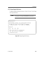
2.2.3 Modify the Boot and Load Files
Edit the boot configuration and load files to match your Freeway setup.
Your Freeway can be set up to use both physical ICP boards and virtual ICP devices.
(Virtual ICPs, or ICP_IP devices, behave just like physical ICP boards except that they
transmit and receive data via an IP network rather than via a serial line.) You must modify one freeway/boot/bootcfg file to include all the information needed.
If you are only using physical ICP boards, edit the boot configuration and load files to
match your Freeway setup as described in this section. For further information about
the boot configuration file, see Section 3.2.
If you are only using virtual ICP devices (ICP_IP), edit the bootcfg.ip configuration file
as described in Section 3.2.1 on page 108.
If you are using both physical ICP boards and virtual ICP devices, modify one freeway/boot/bootcfg file to include all the information needed for each of the physical
devices (ICP boards, described in this section) and virtual devices (ICP_IP devices,
described in Section 3.2.1 on page 108) in your system. Be sure that only one instance
of each device_name is used in this file.
DC 900-1333P
45
Freeway User Guide
The download_script parameter in the boot configuration file defines the path name of
the load file. The load file contains the commands that download the protocol or protocol toolkit software to the ICP.
cd /usr/local/freeway/boot
Step 1: Edit the boot file (bootcfg.xxx)
For a Freeway 1100 with both ICP2424 and ICP2432 boards installed, merge the
bootcfg.isa and bootcfg.pci files to form a new configuration file, including the physical
parameters for each ICP installed in your Freeway. Be sure that only one instance of
each device_name is used in this file.
Edit the boot configuration file (freeway/boot/bootcfg.xxx1) as follows:
1. Uncomment the physical parameters associated with each ICP in your Freeway.
2. For all Freeways, modify the slave_address entry of each ICP to match your configuration. For Freeway 1150/1200/1300, also modify the bus_number entry of each
ICP. Appropriate slave addresses (and bus numbers where applicable) are shown
in a table at the beginning of the boot configuration file.
3. Modify the name of the load file in each download_script entry to match your protocol or toolkit (for example, x25load or sraload).
4. If you have moved the load file from the boot directory, enter the path name for
the load file in each download_script entry. If no path name is provided in the
download_script entry, Freeway searches the System Boot Directory specified in the
Freeway System Boot Parameters menu (Figure 4–27 on page 149) for the load
file indicated.
1. Freeway 1100 uses bootcfg.isa (ICP2424) or bootcfg.pci (ICP2432). Freeway 1150/1200/1300 uses
bootcfg.pci. Freeway 2000/4000/8800 uses bootcfg.vme. Any Freeway using ICP_IP virtual ICP devices may
use bootcfg.ip.
46
DC 900-1333P
2: Software Installation
5. If you will be using the server-resident application (SRA), uncomment the lines
sra_module = sraxxx.o1 and sra_entry = sraInit to load and run the example SRA soft-
ware at boot time. Also modify the tsi_config_file parameter to use the muxcfg.sra
file.
Step 2: Edit the load file (pppload)
Freeway server release G (and later) installs the XIO image files in the freeway/boot directory. Prior to June 1, 1998, the XIO image files were distributed in the freeway/icpcode/icpxxxx/osimpact directory. As a result, the load files provided with protocols with a
release date prior to June 1, 1998 contain a fully qualified path for the protocol and XIO
image files. Such files should be modified to remove the path to the XIO image. This
allows the Freeway to boot the local copy of the XIO image provided in the boot directory with the current Freeway server release.
Edit the load file (freeway/boot/pppload) for your protocol or toolkit as follows:
1. Uncomment the lines associated with the type of ICP in your Freeway.
2. Modify path names as needed. If no path name is provided, Freeway searches the
System Boot Directory specified in the Freeway System Boot Parameters menu
(Figure 4–27 on page 149) for the file to be loaded.
3. Do not change the memory locations (such as 40001200) for the LOAD commands.
For example, to modify the bscload file to load the BSC protocol on an ICP6000, uncomment the lines associated with the ICP6000 as shown in Figure 2–2.
1. xxx = 486 for Freeway1100/1150/1200/1300, 68K for a Freeway 2000/4000/8800 with an MVME 162
CPU, or ppc for a Freeway 2000/4000/8800 with an MVME 2600 CPU.
DC 900-1333P
47
Freeway User Guide
# the below is an example for the icp2424
#
#LOAD xio_2424.mem
801200
#LOAD bsc3270_fw_2424.mem 818000
#LOAD bsc3780_fw_2424.mem 849000
#INIT
818000
#
# the below is an example for the icp2432
#
#LOAD xio_2432.mem
801200
#LOAD bsc3270_fw_2432.mem 818000
#LOAD bsc3780_fw_2432.mem 849000
#INIT
818000
#
# the below is an example for the icp6000
#
LOAD xio_6000.mem
40001200
LOAD bsc3270_fw_6000.mem 40018000
LOAD bsc3780_fw_6000.mem 40049000
INIT
40018000
Figure 2–2: Sample Load File for ICP6000
2.2.4 Build the DLI and TSI Files
Build the DLI and TSI files needed by the Freeway software. A make file is included that
performs this operation.
Step 1: Create the bin and lib directories
1. If it doesn’t already exist, create the op-sys directory, where op-sys is the identifier
for the operating system you are using: dec, hpux, sgi, solaris, or sunos.
cd /usr/local/freeway/client
mkdir op-sys
48
DC 900-1333P
2: Software Installation
2. From your op-sys directory, create the bin and lib directories if they don’t already
exist.
cd op-sys
Scrunched
step 2 and cd
op-sys lines
above to get
bottom list on
this page.
mkdir bin
mkdir lib
Step 2: Run the make file
From the freeway/lib directory, enter one of the following commands depending on the
system you are using. The newly created files will be placed in the proper freeway/client/op-sys/bin or freeway/client/op-sys/lib directory.
cd /usr/local/freeway/lib
make -f Makefile.DEC all
make -f Makefile.HPUX all
make -f Makefile.SGI all
make -f Makefile.SOL all
make -f Makefile.SUN all
(for a DEC UNIX system)
(for an HP/UX system)
(for an SGI system)
(for a Solaris system)
(for a SunOS system)
2.2.5 Build the CS API Library File
If you are using the X.25 protocol, you must build the CS API library file needed by the
Freeway software. A make file is included that performs this operation.
From the freeway/lib/cs_api directory, enter one of the following commands depending
on the system you are using. The newly created file will be placed in the freeway/client/op-sys/lib directory.
cd /usr/local/freeway/lib/cs_api
DC 900-1333P
make -f makefile.dec all
(for a DEC UNIX system)
make -f makefile.hpux all
(for an HP/UX system)
make -f makefile.sgi all
(for an SGI system)
make -f makefile.sol all
(for a Solaris system)
make -f makefile.sun all
(for a SunOS system)
49
Freeway User Guide
2.2.6 Compile the Example Server-Resident Application
To build the example SRA, you must have installed a GNU cross compiler compatible
with the target CPU in your Freeway. It is recommended that you use the GNU cross
compiler provided with the Wind River Systems Tornado tool set. The target CPU-specific portion of the Tornado tool set is called the Board Support Package (BSP). To use
the GNU cross compiler provided with Tornado, you must have purchased the appropriate BSP for your Freeway. The pc486 BSP is required for Freeway 1100/1150/
1200/1300, the mv162 BSP is required for a Freeway 2000/4000/8800 with an MVME
162 CPU, and the mv2604 BSP is required for a Freeway 2000/4000/8800 with an
MVME 2600 CPU.
If you are using a GNU compiler that is not part of a Tornado distribution, you must
make several modifications to the environment files and make files used to build your
SRA. See the Freeway Server Software Toolkit Programmer’s Guide for further information on building the SRA without the Tornado distribution.
Compile the example SRA code using the provided make files.
Step 1: Edit freeway/envcom
If you installed the Freeway server software in a directory other than /usr/local, modify
the path assigned to FWBASE in the freeway/envcom file.
Step 2: Edit freeway/[env486, env68k, or envppc]
If you are using the GNU tool set distributed with Tornado to compile your SRA, and
you installed Tornado in a directory other than /usr/wind, modify the path assigned to
WIND_BASE in the freeway/env486 file (Freeway 1100/1150/1200/1300), freeway/env68k
file (Freeway 2000/4000/8800 with an MVME 162 CPU), or freeway/envppc file
(Freeway 2000/4000/8800 with an MVME 2600 CPU).
50
DC 900-1333P
2: Software Installation
Step 3: Run the make file
From the freeway directory, enter one of the make commands listed below. This compiles all the necessary source code and links the object files to form the SRA object module, which is then placed in the freeway/boot directory. The name of the object module
generated is sra486.o for Freeway 1100/1150/1200/1300, sra68K.o for a Freeway
2000/4000/8800 with an MVME 162 CPU, or srappc.o for a Freeway 2000/4000/8800
with an MVME 2600 CPU.
Your make command must reference the GNU make utility. If the GNU make is not the
first make command in your path, use a full path name to the GNU command, make an
alias to the GNU command, or modify your path appropriately.
cd /usr/local/freeway
For Freeway 1100/1150/1200/1300:
/usr/wind/host/sun4-solaris2/bin/make -f MakeSRA.I486 clean all
For a Freeway 2000/4000/8800 with an MVME 162 CPU:
/usr/wind/host/sun4-solaris2/bin/make -f MakeSRA.68K clean all
For a Freeway 2000/4000/8800 with an MVME 2600 CPU:
/usr/wind/host/sun4-solaris2/bin/make -f MakeSRA.ppc clean all
Remember to modify the boot configuration file as indicated in Section 2.2.3 on page
47 to tell Freeway to load and run the example SRA at boot time and to use muxcfg.sra
as the transport subsystem interface (TSI) configuration file.
Because the example SRA runs the loopback test automatically when Freeway is booted,
install a three-headed loopback cable between links 0 and 1 of ICP 0 and a synchronous
modem before continuing to Section 2.5 on page 93.
DC 900-1333P
51
Freeway User Guide
2.2.7 Compile the Server Toolkit
To build a customized Freeway image using the optional Server Toolkit product, you
must have purchased and installed Tornado from Wind River Systems with the appropriate Board Support Package (BSP) for your Freeway. The pc486 BSP is required for
Freeway 1100/1150/1200/1300, the mv162 BSP is required for a Freeway
2000/4000/8800 with an MVME 162 CPU, and the mv2604 BSP is required for a
Freeway 2000/4000/8800 with an MVME 2600 CPU. Your Tornado installation must
match the version of Tornado used by Protogate to build the Freeway server product.
See the Server Toolkit release notes for the current version of Tornado required for
building the Toolkit.
Caution
When building the Server Toolkit, the Freeway and VxWorks
images in the freeway/boot directory are overwritten. Before executing the make instructions for the Server Toolkit, be sure to
archive the original copies of these files that were delivered with the
Freeway and Server Toolkit distributions so they can be easily
restored.
Compile the Server Toolkit using the provided make files.
Step 1:
Edit freeway/envcom. If you installed the server toolkit software in a directory
other than /usr/local, modify the path assigned to FWBASE in the freeway/envcom file.
Step 2:
Edit freeway/[env486, env68k, or envppc]. If you installed Tornado in a direc-
tory other than /usr/wind, modify the path assigned to WIND_BASE in the freeway/env486
file (Freeway 1100/1150/1200/1300), freeway/env68k file (Freeway
2000/4000/8800 with an MVME 162 CPU) or freeway/envppc file (Freeway
2000/4000/8800 with an MVME 2600 CPU).
52
DC 900-1333P
2: Software Installation
Step 3:
Run the make file.
From the freeway directory, enter one of the following commands. This compiles all the
necessary source code from the VxWorks Board Support Package as modified by Protogate and links the object files with the Freeway server library, the Freeway API library,
and the VxWorks system library to build the Freeway server image, VxWorks image, and
loadable Freeway server module for the specified Freeway architecture and place them
in the freeway/boot directory. Your make command must reference the GNU make utility. If the GNU make is not the first make command in your path, use a full path name
to the GNU command, make an alias to the GNU command, or modify your path
appropriately.
For Freeway 1100/1150/1200/1300:
/usr/wind/host/sun4-solaris2/bin/make -f MakeSTK.I486 clean all
For a Freeway 2000/4000/8800 with an MVME 162 CPU:
/usr/wind/host/sun4-solaris2/bin/make -f MakeSTK.68K clean all
For a Freeway 2000/4000/8800 with an MVME 2600 CPU:
/usr/wind/host/sun4-solaris2/bin/make -f MakeSTK.ppc clean all
2.2.8 Build the Loopback Tests
For all protocols and toolkits except the example server-resident application, you must
build the loopback tests supplied with the Freeway software. A make file is included that
performs this operation.
Step 1: Edit the client TSI configuration files in freeway/client/test/ppp
For all protocols and toolkits except the example server-resident application, edit each
of the client transport subsystem interface (TSI) configuration files listed in Table 2–3,
DC 900-1333P
53
Freeway User Guide
changing the default value of the Freeway server parameter, freeway_0, to the name (or
Internet address) of your current Freeway server.
A client TSI configuration file might reference the server parameter more than once,
and must be changed at each occurrence.
Note
If the server name and Internet address have not already been
added to the /etc/hosts file during hardware installation, refer to
Section 2.1.3 on page 34.
Note
There is a separate server TSI configuration file, usually called
muxcfg , that does not require modification for most sites.
Table 2–3: Client TSI Configuration Files (UNIX)
AUTODIN
AWS
BSC3270
BSC2780/3780
autodinaltcfg
awsaltcfg
bsc3270altcfg
bsc3780altcfg
DDCMP
FMP
ADCCP NRM
Protocol Toolkit
ddcmpaltcfg
fmpaltcfg
nrmaltcfg
spsaltcfg
STD1200B
Military/Government
Protocol
X.25/HDLC
s12altcfg
miltcfg
apitcfg
Step 2: Edit the DLI configuration files (Freeway 1100/1150/1200/1300) in freeway/client/test/ppp
If you are installing any protocol on Freeway 2000/4000/8800, skip to Step 3.
54
DC 900-1333P
2: Software Installation
If you are installing DDCMP, protocol toolkit, or X.25 on Freeway 1100/1150/
1200/1300, skip to Step 3. The electrical interface for DDCMP and protocol toolkit is
specified when you run the loopback test. The electrical interface for X.25 is specified in
the .setup file in the freeway/client/test/x25mgr directory.
If you are installing AWS, BSC, or FMP on Freeway 1100/1150/1200/1300, change to the
freeway/client/test/ppp directory. Specify the electrical interface by editing the data link
interface (DLI) configuration files listed in Table 2–4.
Open each file and locate each occurrence of ElecInterface. Remove the double slashes
(//) from the beginning of each ElecInterface line. If you will not be using the default
EIA-232 electrical interface, replace EIA232 with one of the following:
•
EIA449
•
EIA530
•
V35
Table 2–4: Client DLI Configuration Files (UNIX)
AWS
BSC3270
BSC2780/3780
FMP
awsaldcfg
bsc3270aldcfg
bsc3780aldcfg
fmpaldcfg
Step 3: Run the make file
From the freeway/client/test/ppp directory, enter one of the following commands
depending on the system you are using. The newly created files will be placed in the freeway/client/op-sys/bin directory.
DC 900-1333P
make -f makefile.dec all
(for a DEC UNIX system)
make -f makefile.hpux all
(for an HP/UX system)
make -f makefile.sgi all
(for an SGI system)
55
Freeway User Guide
make -f makefile.sol all
(for a Solaris system)
make -f makefile.sun all
(for a SunOS system)
Go to Section 2.5 on page 93 for the next step in the installation procedure. For a
description of the Freeway files you have just installed onto your boot server, refer to
Appendix B.
56
DC 900-1333P
2: Software Installation
2.3 Install the Freeway Software onto a VMS Computer
This section describes how to install the Freeway software from the distribution media
onto a VMS computer. Later in these procedures you will use this computer as a boot
server to boot Freeway.
Note
After you have followed the detailed software installation procedures outlined in this chapter, you can refer to the “Installation at
a Glance” summary in Appendix A as a quick reference for future
installations.
2.3.1 Contents of the VMS Distribution Media
The Freeway software for VMS computers is distributed on a TK50/TK70 cartridge in
Files-11 format.
2.3.1.1 Server/Client Software
The server/client distribution media is labeled Freeway Server Software.
The following files are in the FREEWAY directory:
•
README.SER provides general information about the server software
•
RELNOTES.SER provides specific information about the current release of the
server software
•
The ENV and MAKE files are for the example server-resident application, which is
not available on VMS
DC 900-1333P
57
2/3/99 Ginni: I
added CD
installation to
unix and nt
sections, but
not here.
Freeway User Guide
The following general files are in the FREEWAY.BOOT directory:
•
BOOTCFG.IP is an example boot configuration file for ICP_IP virtual devices
•
BOOTCFG.ISA is the boot configuration file for a Freeway 1100 with ICP2424s
(ISAbus boards)
•
BOOTCFG.PCI is the boot configuration file for a Freeway 1100 with ICP2432s
(PCI boards) and Freeway 1150/1200/1300
•
BOOTCFG.VME is the boot configuration file for Freeway 2000/4000/8800s
•
FW486 is the system boot file for Freeway 1100/1150/1200/1300
•
FW162 is the standard system boot file for a Freeway 2000/4000/8800 with an
MVME 162 CPU 9 or CPU 10
•
FW162L is the limited memory system boot file for a Freeway 2000/4000/8800
with an MVME 162 CPU 7 or CPU 8
•
FW2604 is the system boot file for a Freeway 2000/4000/8800 with an MVME 2600
CPU
•
FW486.SYM is the symbol table for the Freeway 1100/1150/1200/1300 boot image
•
FW162.SYM is the standard symbol table for the boot image of a Freeway
2000/4000/8800 with an MVME 162 CPU 9 or CPU 10
•
FW162L.SYM is the limited memory symbol table for the boot image of a Freeway
2000/4000/8800 with an MVME 162 CPU 7 or CPU 8
•
FW2604.SYM is the symbol table for the boot image of a Freeway 2000/4000/8800
with an MVME 2600 CPU
•
MUXCFG1 is the server TSI configuration file
1. The Military/Government protocol uses MILMUXCFG.
58
DC 900-1333P
2: Software Installation
•
XIO_2424.MEM XIO_2432.MEM, or XIO_6000.MEM1 are the executable objects
for the system-services module
Various files specific to the server-resident application (SRA), such as buffer.size, ftst,
and the sra files, are also in the FREEWAY.BOOT directory; however, SRA is not available on VMS.
The data link interface (DLI) and transport subsystem interface (TSI) software is in the
FREEWAY.LIB directory.
2.3.1.2 Protocol or Protocol Toolkit Software
The protocol or protocol toolkit distribution media is labeled Freeway [Name] Software.
Note
The ppp variable mentioned below specifies the particular protocol
or toolkit you are using (refer to Table 2–2 on page 31).
The following files are in the FREEWAY directory:
•
README.ppp provides general information about the protocol or protocol toolkit
software
•
RELNOTES.ppp provides specific information about the current release of the
protocol or protocol toolkit software
The load file, pppLOAD, is in the FREEWAY.BOOT directory.
1. The Freeway server release G (and later) installs the XIO image files in the FREEWAY.BOOT directory. Prior to June 1, 1998, the XIO image files were distributed in the FREEWAY.ICPCODE.ICPXXXX.OSIMPACT directory. As a result, the load files provided with protocols with a release date
prior to June 1, 1998 contain a fully qualified path for the protocol and XIO image files. Such files should
be modified to remove the path to the XIO image. This allows Freeway to boot the local copy of the XIO
image provided in the FREEWAY.BOOT directory with the current Freeway server release.
DC 900-1333P
59
Freeway User Guide
For software releases prior to June 1, 1998, the executable object for the protocol or protocol
toolkit
software,
ppp_FW_2424.MEM1,
ppp_FW_2432.MEM9,
ppp_FW_6000.MEM2, was distributed in the FREEWAY.ICPCODE.ICPXXXX.PROTOCOLS directory. For releases after June 1, 1998, these files are in the FREEWAY.BOOT
directory.
Source code for the loopback tests is in the FREEWAY.CLIENT.TEST.ppp directory.
Source code for the protocol toolkit is in the FREEWAY.ICPCODE.PROTO_KIT directory.
Source code for the OS/Impact delivered with the protocol toolkit is in the
FREEWAY.ICPCODE.OS_SDS directory.
2.3.2 Retrieve Files from the VMS Distribution Media
The software distribution media contains several VMS BACKUP savesets. To install the
Freeway software from the distribution media onto your VMS computer, use the
VMSINSTAL utility as described in the following procedure.
Caution
Remember that installing new software overwrites the previous
software.
After the distribution media is mounted, the procedure is automated and only requires
that you respond to menu prompts. Console displays are shown in typewriter type and
your responses are shown in bold type. Follow each entry with a carriage return. The
abbreviation ddcu signifies that a device name is required.
1. For the example server-resident application, the executable object is SPS_FW_2424.MEM or
SPS_FW_2432.MEM for Freeway 1100/1150/1200/1300.
2. For the example server-resident application, the executable object is SPS_FW_6000.MEM for Freeway 2000/4000/8800.
60
DC 900-1333P
2: Software Installation
You might find it useful to perform the installation at a hardcopy terminal. This provides a printed record that you can use for troubleshooting if needed.
Step 1:
On the boot server (previously configured as described in Section 2.1), log in
to an account that has system-manager privileges.
Step 2:
Change to the default directory called SYS$SYSDEVICE. The installation
procedure is designed to use this default directory and the directory structure under it.
Note
It is highly recommended that you use the default directory structure.
If you install the software in a non-default directory, you must later
modify certain files as described in Section 2.5.
Step 3:
Insert the protocol distribution media into the appropriate drive. Run
VMSINSTAL as follows to copy the files from each distribution media to your VMS
computer (Vnnnn is the current software version number). Then insert the server/client distribution media and retrieve the files in the same manner.
$ @SYS$UPDATE:VMSINSTAL
OpenVMS VAX Software Product Installation Procedure Vnnnn
It is today’s date at current time.
Enter a question mark (?) at any time for help.
The computer checks the following conditions:
•
Are you logged in to the system manager’s account? You should install the software from that account; however, any account with the necessary privileges is
acceptable.
DC 900-1333P
61
Freeway User Guide
•
Do you have adequate account quotas for installing software? VMSINSTAL checks
for the various quota values.
•
Is DECnet up and running? (This is only checked by older versions of VMSINSTAL.)
•
Are any users logged on the system? Problems might occur if someone tries to use
Freeway while you are installing a new release of the software.
Step 4:
If there are potential problems with the account quotas, the computer dis-
plays:
The following account quotas may be too low.
The computer lists the account quotas that might be too low. Next, it lists any other
active processes.
If any potentially conflicting conditions are noted, the computer gives you the opportunity to stop the installation by displaying the following message:
* Do you want to continue anyway [NO]?
If you answer yes, the computer asks:
Are you satisfied with the backup of your system disk [YES]?
If you answer no, the installation stops so you can save your data before restarting the
installation.
Step 5:
If you proceed with the installation, the computer displays the following mes-
sage. Remember that ddcu means a device name.
* Where will the distribution volumes be mounted: ddcu:
For ddcu, substitute a device name such as MUA0, MKA100, DUAl, or something similar.
62
DC 900-1333P
2: Software Installation
Step 6: The computer displays:
Enter the products to be processed from the first distribution
volume set.
* Products: *
Enter an asterisk (this causes all products to be installed).
Step 7: Depending on the release number, you will see either
* Enter installation options you wish to use (none):
or
* Options:
Refer to Digital’s VMS Installation Guide for a list of the VMSINSTAL options and how
to enter them. Press <return> to select the standard installation options.
Step 8:
The computer displays:
Please mount the first volume of the set on ddcu:
Note that ddcu is the device name you entered in Step 5.
Step 9: Mount the distribution media. The computer asks:
* Are you ready? y
Answer yes by entering y followed by <return>. The computer displays a mount message. Depending on the speed of your system, several minutes will pass before the next
message is displayed.
DC 900-1333P
63
Freeway User Guide
The following products will be processed:
The computer displays product names, then displays the following (Vnnnn is the current software version number):
Beginning installation of Product Vnnnn at current time.
%VMSINSTAL-I-RESTORE Restoring product save set A ...
The computer displays other verification messages.
Caution
The next two steps ask you to specify the disk and directory locations where the software will be installed. It is highly recommended
that you use the default locations. If you do not, you must later
modify certain files as described in Section 2.5.
Step 10:
The computer displays:
This installation procedure will place the files on device
SYS$SYSDEVICE.
* Is this acceptable [Y]? y
Press <return> to answer yes (this is highly recommended). If you answer no, you are
prompted to enter the name of a target disk.
Step 11:
The computer displays:
This installation procedure will place the product files in
directory [FREEWAY...]
on device ddcu
* Is this acceptable [Y]? y
64
DC 900-1333P
2: Software Installation
Remember that ddcu means a device name. Press <return> to answer yes (this is highly
recommended). If you answer no, you are prompted to enter the name of a directory.
Step 12: The computer displays:
There are no more questions. The installation will proceed.
The procedure completes automatically without the need for you to take any action.
Depending on the speed of your system, this will take several minutes.
While moving the files to the appropriate directory, the computer displays the README
file that includes configuration information such as the part, version, and serial numbers for the distribution, then it displays:
%VMSINSTAL-I-MOVEFILES, Files will now be moved to their target directories...
Installation of Product Vnnnn completed at current time.
Step 13: The computer displays:
Enter the products to be processed from the next distribution volume set.
* Products:
If you will be installing another protocol, enter an asterisk (*) to continue. When there
are no other distribution sets, enter exit. The computer displays:
VMSINSTAL procedure done at current time.
The Freeway software is now installed onto your computer’s disk.
DC 900-1333P
65
Freeway User Guide
2.3.3 Modify the Boot and Load Files
Edit the boot configuration and load files to match your Freeway setup.
Your Freeway can be set up to use both physical ICP boards and virtual ICP devices.
(Virtual ICPs, or ICP_IP devices, behave just like physical ICP boards except that they
transmit and receive data via an IP network rather than via a serial line.) You must modify one [FREEWAY.BOOT]BOOTCFG file to include all the information needed.
If you are only using physical ICP boards, edit the boot configuration and load files to
match your Freeway setup as described in this section. For further information about
the boot configuration file, see Section 3.2.
If you are only using virtual ICP devices (ICP_IP), edit the BOOTCFG.IP configuration
file as described in Section 3.2.1 on page 108.
If you are using both physical ICP boards and virtual ICP devices, modify one [FREEWAY.BOOT]BOOTCFG file to include all the information needed for each of the physi-
cal devices (ICP boards, described in this section) and virtual devices (ICP_IP devices,
described in Section 3.2.1 on page 108) in your system. Be sure that only one instance
of each device_name is used in this file.
The download_script parameter in the boot configuration file defines the path name of
the load file. The load file contains the commands that download the protocol or protocol toolkit software to the ICP.
SET DEF SYS$SYSDEVICE:[FREEWAY.BOOT]
Step 1: Edit the boot file (bootcfg.xxx)
For a Freeway 1100 with both ICP2424 and ICP2432 boards installed, merge the
BOOTCFG.ISA and BOOTCFG.PCI files to form a new configuration file, including the
physical parameters for each ICP installed in your Freeway. Be sure that only one
instance of each device_name is used in this file.
66
DC 900-1333P
2: Software Installation
Edit the boot configuration file ([FREEWAY.BOOT]BOOTCFG.xxx1) as follows:
1. Uncomment the physical parameters associated with each ICP in your Freeway.
2. For all Freeways, modify the slave_address entry of each ICP to match your configuration. For Freeway 1150/1200/1300, also modify the bus_number entry of each
ICP. Appropriate slave addresses (and bus numbers where applicable) are shown
in a table at the beginning of the boot configuration file.
3. Modify the name of the load file in each download_script entry to match your protocol or toolkit (for example, X25LOAD or AWSLOAD).
4. If you have moved the load file from the BOOT directory, enter the path name for
the load file in each download_script entry. If no path name is provided in the
download_script entry, Freeway searches the System Boot Directory specified in the
Freeway System Boot Parameters menu (Figure 4–27 on page 149) for the load
file indicated.
1. Freeway 1100 uses BOOTCFG.ISA (ICP2424) or BOOTCFG.PCI (ICP2432). Freeway
1150/1200/1300 uses BOOTCFG.PCI. Freeway 2000/4000/8800 uses BOOTCFG.VME. Any Freeway using
ICP_IP virtual ICP devices may use BOOTCFG.IP.
DC 900-1333P
67
Freeway User Guide
Step 2: Edit the load file (pppLOAD)
Freeway server release G (and later) installs the XIO image files in the FREEWAY.BOOT
directory. Prior to June 1, 1998, the XIO image files were distributed in the FREEWAY.
ICPCODE.ICPXXXX.OSIMPACT directory. As a result, the load files provided with pro-
tocols with a release date prior to June 1, 1998 contain a fully qualified path for the protocol and XIO image files. Such files should be modified to remove the path to the XIO
image. This allows the Freeway to boot the local copy of the XIO image provided in the
BOOT directory with the current Freeway server release.
Edit the load file ([FREEWAY.BOOT]pppLOAD) for your protocol or toolkit as follows:
1. Uncomment the lines associated with the type of ICP in your Freeway.
2. Modify path names as needed. If no path name is provided, Freeway searches the
System Boot Directory specified in the Freeway System Boot Parameters menu
(Figure 4–27 on page 149) for the file to be loaded.
3. Do not change the memory locations (such as 40001200) for the LOAD commands.
For example, to modify the BSCLOAD file to load the BSC protocol on an ICP2432,
uncomment the lines associated with the ICP2432 as shown in Figure 2–3.
68
DC 900-1333P
2: Software Installation
# the below is an example for the icp2424
#
#LOAD xio_2424.mem
801200
#LOAD bsc3270_fw_2424.mem 818000
#LOAD bsc3780_fw_2424.mem 849000
#INIT
818000
#
# the below is an example for the icp2432
#
LOAD xio_2432.mem
801200
LOAD bsc3270_fw_2432.mem 818000
LOAD bsc3780_fw_2432.mem 849000
INIT
818000
#
# the below is an example for the icp6000
#
#LOAD xio_6000.mem
40001200
#LOAD bsc3270_fw_6000.mem 40018000
#LOAD bsc3780_fw_6000.mem 40049000
#INIT
40018000
Figure 2–3: Sample Load File for ICP2432
2.3.4 Build the DLI and TSI Files
Build the DLI and TSI files needed by the Freeway software. A make command is
included that performs this operation.
Step 1: Create the BIN and LIB directories
1. If it doesn’t already exist, create the OP-SYS directory, where OP-SYS is the identifier for the operating system you are using: AXP_MULTINET, AXP_TCPWARE, or
AXP_UCX.
SET DEF SYS$SYSDEVICE:[FREEWAY.CLIENT]
CREATE /DIR [.OP-SYS]
DC 900-1333P
69
Freeway User Guide
2. From your OP-SYS directory, create the BIN and LIB directories if they don’t
already exist.
SET DEF OP-SYS
CREATE /DIR [.BIN]
CREATE /DIR [.LIB]
Step 2: Run the MAKE_DLI_TSI command
From the FREEWAY.LIB directory, enter one of the following commands. The newly
created files will be placed in the proper FREEWAY.CLIENT.OP-SYS.BIN or FREEWAY.
CLIENT.OP-SYS.LIB directory.
SET DEF SYS$SYSDEVICE[FREEWAY.LIB]
@MAKE_DLI_TSI "" MULTINET
(for VMS with Multinet)
@MAKE_DLI_TSI "" TCPWARE
(for VMS with TCPware)
@MAKE_DLI_TSI "" UCX
(for VMS with UCX)
2.3.5 Build the CS API Library File
If you are using the X.25 protocol, you must build the CS API library file needed by the
Freeway software. A make command is included that performs this operation.
From the FREEWAY.LIB.CS_API directory, enter one of the following commands. The
newly created file will be placed in the FREEWAY.CLIENT.OP-SYS.LIB directory.
SET DEF SYS$SYSDEVICE[FREEWAY.LIB.CS_API]
70
@MAKEVMS "" MULTINET
(for VMS with Multinet)
@MAKEVMS "" TCPWARE
(for VMS with TCPware)
@MAKEVMS "" UCX
(for VMS with UCX)
DC 900-1333P
2: Software Installation
2.3.6 Build the QIO/SQIO API Library File
If you have purchased the QIO/SQIO API, you must build the library file needed by the
Freeway software. A make command is included that performs this operation.
From the FREEWAY.LIB.QAPI directory, enter one of the following commands. The
newly created file will be placed in the FREEWAY.CLIENT.OP-SYS.LIB directory.
SET DEF SYS$SYSDEVICE[FREEWAY.LIB.QAPI]
@MAKEVMS "" MULTINET
(for VMS with Multinet)
@MAKEVMS "" TCPWARE
(for VMS with TCPware)
@MAKEVMS "" UCX
(for VMS with UCX)
2.3.7 Build the Loopback Tests
You must build the loopback tests supplied with the Freeway software. A command file
called MAKEVMS.COM is included that performs these operations.
Step 1: Edit the client TSI configuration files in FREEWAY.CLIENT.TEST.ppp
Edit each of the client transport subsystem interface (TSI) configuration files listed in
Table 2–5, changing the default value of the Freeway server parameter, freeway_0, to the
name (or Internet address) of your current Freeway server.
A client TSI configuration file might reference the server parameter more than once,
and must be changed at each occurrence.
Note
If the server name and Internet address have not already been
defined during hardware installation, refer to Section 2.1.3 on
page 34.
DC 900-1333P
71
Freeway User Guide
Note
There is a separate server TSI configuration file, usually called
MUXCFG, which does not require modification for most sites.
Table 2–5: Client TSI Configuration Files (UNIX)
AUTODIN
AWS
BSC3270
BSC2780/3780
AUTODINALTCFG
AWSALTCFG
DDCMP
FMP
ADCCP NRM
Protocol Toolkit
DDCMPALTCFG
FMPALTCFG
NRMALTCFG
SPSALTCFG
STD1200B
Military/Government
Protocol
X.25/HDLC
S12ALTCFG
MILTCFG
APITCFG
BSC3270ALTCFG BSC3780ALTCFG
Step 2: Edit the DLI configuration files (Freeway 1100/1150/1200/1300) in FREEWAY. CLIENT.TEST.ppp
If you are installing any protocol on Freeway 2000/4000/8800, skip to Step 3 on page 73.
If
you
are
installing
DDCMP,
protocol
toolkit,
or
X.25
on
Freeway
1100/1150/1200/1300, skip to Step 3 on page 73. The electrical interface for DDCMP
and protocol toolkit is specified when you run the loopback test. The electrical interface
for X.25 is specified in the .SETUP file in the [FREEWAY.CLIENT.TEST.X25MGR]
directory.
If you are installing AWS, BSC, or FMP on Freeway 1100/1150/1200/1300, you must
specify the electrical interface by editing the data link interface (DLI) configuration files
listed in Table 2–6.
72
DC 900-1333P
2: Software Installation
Open each file and locate each occurrence of ElecInterface. Remove the double slashes
(//) from the beginning of each ElecInterface line. If you will not be using the default
EIA-232 electrical interface, replace EIA232 with one of the following:
•
EIA449
•
EIA530
•
V35
Table 2–6: Client DLI Configuration Files (VMS)
AWS
AWSALDCFG
BSC3270
BSC2780/3780
BSC3270ALDCF BSC3780ALDCF
G
G
FMP
FMPALDCFG
Step 3: Run the MAKEVMS command
From the FREEWAY.CLIENT.TEST.ppp directory, enter one of the following commands. The newly created files will be placed in the FREEWAY.CLIENT.OP-SYS.BIN
directory.
@MAKEVMS "" MULTINET
(for VMS with Multinet)
@MAKEVMS "" TCPWARE
(for VMS with TCPware)
@MAKEVMS "" UCX
(for VMS with UCX)
Depending on the speed of your system, this will take several minutes.
DC 900-1333P
73
Freeway User Guide
Note
The installed files have an owner User Identification Code
(OWNER_UIC) of [1,4] that corresponds to the SYSTEM account.
To be able to access the installed files, you must select (or create) a
user account intended to use Freeway and set the ownership of all
Freeway files and directories to that particular User Identification
Code.
Go to Section 2.5 on page 93 for the next step in the installation procedure. For a
description of the Freeway files you have just installed onto your boot server, refer to
Appendix B.
74
DC 900-1333P
2: Software Installation
2.4 Install the Freeway Software onto a Windows NT Computer
This section describes how to install the Freeway software from the distribution media
onto a Windows NT (Alpha or Intel) computer. Later in these procedures you will use
this computer as a boot server to boot Freeway.
Note
After you have followed the detailed software installation procedures outlined in this chapter, you can refer to the “Installation at
a Glance” summary in Appendix A as a quick reference for future
installations.
2.4.1 Contents of the Windows NT Distribution Media
Freeway software for Alpha NT and Intel NT computers is distributed on CD-ROM or
on 3.5-inch diskettes.
2.4.1.1 Server/Client Software
The server/client distribution media is labeled Freeway Server Software.
The following files are in the freeway directory:
•
readme.ser provides general information about the server software
•
relnotes.ser provides specific information about the current release of the server
software
•
env486, env68k, envcom, and envppc are environment definition files for the exam-
ple server-resident application (SRA)
•
MakeSRA.I486, MakeSRA.68K , and MakeSRA.ppc are make files for the example
SRA
DC 900-1333P
75
Freeway User Guide
The following files are in the freeway\boot directory:
•
bootcfg.ip is an example boot configuration file for ICP_IP virtual devices
•
bootcfg.isa is the boot configuration file for a Freeway 1100 with ICP2424s (ISA-
bus boards)
•
bootcfg.pci is the boot configuration file for a Freeway 1100 with ICP2432s (PCI
boards) and Freeway 1150/1200/1300
•
bootcfg.vme is the boot configuration file for Freeway 2000/4000/8800s
•
fw486 is the system boot file for Freeway 1100/1150/1200/1300
•
fw162 is the standard system boot file for a Freeway 2000/4000/8800 with an
MVME 162 CPU 9 or CPU 10
•
fw162l is the limited memory system boot file for a Freeway 2000/4000/8800 with
an MVME 162 CPU 7 or CPU 8
•
fw2604 is the system boot file for a Freeway 2000/4000/8800 with an MVME 2600
CPU
•
fw486.sym is the symbol table for the Freeway 1100/1150/1200/1300 boot image
•
fw162.sym is the standard symbol table for the boot image for a Freeway
2000/4000/8800 with an MVME 162 CPU 9 or CPU 10
•
fw162l.sym is the limited memory symbol table for the boot image for a Freeway
2000/4000/8800 with an MVME 162 CPU 7 or CPU 8
•
fw2604.sym is the symbol table for the boot image of a Freeway 2000/4000/8800
with an MVME 2600 CPU
•
muxcfg 1 is the server TSI configuration file
1. The example server-resident application use muxcfg.sra. The Military/Government protocol uses
milmuxcfg.
76
DC 900-1333P
2: Software Installation
•
xio_2424.mem, xio_2432.mem, or xio_6000.mem1 are the executable objects for the
system-services module
The following files specific to the server-resident application (SRA) are also in the freeway\boot directory:
•
buffer.size is the buffer size file for the protocol toolkit used with for the example
SRA
•
ftstdcfg , ftsttcfg, sradcfg , and sratcfg are the data link interface (DLI) and transport
subsystem interface (TSI) configuration files for the example SRA
•
fw486d is the debug version of the system boot file for Freeway 1100/1150/
1200/1300
•
fw162d is the standard debug version of the system boot file for a Freeway
2000/4000/8800 with an MVME 162 CPU 9 or CPU 10
•
fw2604d is the debug version of the system boot file for a Freeway 2000/4000/8800
with an MVME 2600 CPU
•
fw486d.sym is the symbol table for the Freeway 1100/1150/1200/1300 debug
server image
•
fw162d.sym is the standard symbol table for the debug server image for a Freeway
2000/4000/8800 with an MVME 162 CPU 9 or CPU 10
•
fw2604d.sym is the symbol table for the debug server image for a Freeway
2000/4000/8800 with an MVME 2600 CPU
1. The Freeway server release G (and later) installs the XIO image files in the freeway\boot directory.
Prior to June 1, 1998, the XIO image files were distributed in the freeway\icpcode\icpxxxx\osimpact directory.
As a result, the load files provided with protocols with a release date prior to June 1, 1998 contain a fully
qualified path for the protocol and XIO image files. Such files should be modified to remove the path to the
XIO image. This allows Freeway to boot the local copy of the XIO image provided in the freeway/boot directory with the current Freeway server release.
DC 900-1333P
77
Freeway User Guide
•
sps_fw_2432.mem, sps_fw_6000.mem, and sps_fw_2424.mem are the executable
objects for the protocol toolkit used with the example SRA
•
sra486.o, sra68K.o, and srappc.o are the object modules for the example SRA
•
sraload is the load file for the example SRA
•
muxcfg.sra is the server TSI configuration file used with the example SRA
The example SRA source code is in the freeway\client\test\sra directory.
The data link interface (DLI) and transport subsystem interface (TSI) software is in the
freeway\lib directory.
2.4.1.2 Server Toolkit Software
The Server Toolkit distribution media is labeled Freeway Server Toolkit Software.
The following files delivered with the Server Toolkit are in the freeway directory:
•
readme.stk provides general information about the Server Toolkit software
•
relnotes.stk provides specific information about the current release of the Server
Toolkit software
•
MakeSTK.I486 , MakeSTK.68K, and MakeSTK.ppc are make files for the Server
Toolkit software
The following files are in the freeway\boot directory:
•
vx162, vx486, and vx2604 are VxWorks operating system images
•
vx162.sym, vx486.sym, and vx2604.sym are symbol tables for the VxWorks operat-
ing system images
A binary object file (usrSimpact.o) providing an entry point for the Freeway software is
stored
in
the
freeway\server\bin\mv162,
freeway\server\bin\mv2604,
and
free-
way\server\bin\pc486 directories.
78
DC 900-1333P
2: Software Installation
The Freeway server software library archive called libserv.a and the server DLI/TSI
object library called libvxwfw.o are stored in the freeway\server\lib\mv162, freeway\server\lib\mv2604, and freeway\server\lib\pc486 directories.
Source code that may be modified to tailor the VxWorks operating system of the
Freeway server is provided in the freeway\server\vw\config directory.
Make files for rebuilding the server DLI/TSI object library are provided in the freeway\lib directory.
2.4.1.3 Protocol or Protocol Toolkit Software
The protocol or protocol toolkit distribution media is labeled Freeway [Name] Software.
Note
The ppp variable mentioned below specifies the particular protocol
or toolkit you are using (refer to Table 2–2 on page 31).
The following files are in the freeway directory:
•
readme.ppp provides general information about the protocol or protocol toolkit
software
•
relnotes.ppp provides specific information about the current release of the proto-
col or protocol toolkit software
The load file, pppload, is in the freeway\boot directory.
For software releases prior to June 1, 1998, the executable object for the protocol or protocol toolkit software, ppp_fw_2424.mem1, ppp_fw_2432.mem14, ppp_fw_6000.mem2, was
1. For the example server-resident application, the executable object is sps_fw_2424.mem or
sps_fw_2432.mem for Freeway 1100/1150/1200/1300.
DC 900-1333P
79
Freeway User Guide
distributed in the freeway\icpcode\icpxxxx\protocols directory. For releases after June 1,
1998, these files are in the freeway\boot directory.
Source code for the loopback tests is in the freeway\client\test\ppp directory.
Source code for the protocol toolkit is in the freeway\icpcode\proto_kit directory.
Source code for the OS/Impact delivered with the protocol toolkit is in the freeway\ icpcode\os_sds directory.
2.4.2 Retrieve Files from the Windows NT Distribution Media
For CD-ROM distributions, see Section 2.4.2.1. For 3.5" diskette distributions, see
Section 2.4.2.2.
Caution
Remember that installing new software overwrites the previous
software.
2.4.2.1 CD-ROM Distributions
Insert the CD into the drive. If your Windows NT computer is set up for auto-run of
CD-ROMs and you have a browser enabled, the installation page will come up automatically. Click on the product you have purchased, then click on Self-extracting
Zip/InstallShield and follow the instructions on the screen.
If your Windows NT computer has a browser enabled, but your computer is not set up
for auto-run of CD-ROMs, click on the index.html file on the CD-ROM to open the
installation page. Click on the product you have purchased, then click on Self-extracting
Zip/InstallShield and follow the instructions on the screen.
2. For the example server-resident application, the executable object sps_fw_6000.mem for Freeway
2000/ 4000/8800.
80
DC 900-1333P
2: Software Installation
If your Windows NT computer does not have a browser enabled, open the readme.txt file
on the CD-ROM and follow the instructions.
2.4.2.2 Diskette Distributions
Use the following procedure to install the Freeway software from the diskettes onto your
Alpha NT or Intel NT computer.
Step 1:
On the boot server (previously configured as described in Section 2.1), log in
to a privileged account.
Step 2:
Insert the diskette in the appropriate drive and type:
a:\setup
or
b:\setup
The setup program prompts you for the base directory for the installation. The default
directory is C:. Follow the instructions on the screen. When the main prompt appears
again, install the next diskette.
DC 900-1333P
81
Freeway User Guide
2.4.3 Modify the Boot and Load Files
Edit the boot configuration and load files to match your Freeway setup.
Your Freeway can be set up to use both physical ICP boards and virtual ICP devices.
(Virtual ICPs, or ICP_IP devices, behave just like physical ICP boards except that they
transmit and receive data via an IP network rather than via a serial line.) You must modify one freeway\boot\bootcfg file to include all the information needed.
If you are only using physical ICP boards, edit the boot configuration and load files to
match your Freeway setup as described in this section. For further information about
the boot configuration file, see Section 3.2.
If you are only using virtual ICP devices (ICP_IP), edit the bootcfg.ip configuration file
as described in Section 3.2.1 on page 108.
If you are using both physical ICP boards and virtual ICP devices, modify one freeway\boot\bootcfg file to include all the information needed for each of the physical
devices (ICP boards, described in this section) and virtual devices (ICP_IP devices,
described in Section 3.2.1 on page 108) in your system. Be sure that only one instance
of each device_name is used in this file.
The download_script parameter in the boot configuration file defines the path name of
the load file. The load file contains the commands that download the protocol or protocol toolkit software to the ICP.
cd C:\freeway\boot
Step 1: Edit the boot file (bootcfg.xxx)
For a Freeway 1100 with both ICP2424 and ICP2432 boards installed, merge the
bootcfg.isa and bootcfg.pci files to form a new configuration file, including the physical
parameters for each ICP installed in your Freeway. Be sure that only one instance of
each device_name is used in this file.
82
DC 900-1333P
2: Software Installation
Edit the boot configuration file (freeway\boot\bootcfg.xxx1) as follows:
1. Uncomment the physical parameters associated with each ICP in your Freeway.
2. For all Freeways, modify the slave_address entry of each ICP to match your configuration. For Freeway 1150/1200/1300, also modify the bus_number entry of each
ICP. Appropriate slave addresses (and bus numbers where applicable) are shown
in a table at the beginning of the boot configuration file.
3. Modify the name of the load file in each download_script entry to match your protocol or toolkit (for example, x25load or sraload).
4. If you have moved the load files from the boot directory, enter the path names for
the load files in each download_script entry. If no path name is provided in the
download_script entry, Freeway searches the System Boot Directory specified in the
Freeway System Boot Parameters menu (Figure 4–27 on page 149) for the load
file indicated.
5. If you will be using the server-resident application (SRA), uncomment the lines
sra_module = sraxxx.o2 and sra_entry = sraInit to load and run the example SRA soft-
ware at boot time. Also modify the tsi_config_file parameter to use the muxcfg.sra
file.
Step 2: Edit the load file (pppload)
The Freeway server release G (and later) installs the XIO image files in the freeway\boot
directory. Prior to June 1, 1998, the XIO image files were distributed in the freeway\icpcode\icpxxxx\osimpact directory. As a result, the load files provided with protocols with a
1. Freeway 1100 uses bootcfg.isa (ICP2424) or bootcfg.pci (ICP2432). Freeway 1150/1200/1300 uses
bootcfg.pci. Freeway 2000/4000/8800 uses bootcfg.vme. Any Freeway using ICP_IP virtual ICP devices may
use bootcfg.ip.
2. xxx = 486 for Freeway1100/1150/1200/1300, 68K for a Freeway 2000/4000/8800 with an MVME 162
CPU, or ppc for a Freeway 2000/4000/8800 with an MVME 2600 CPU.
DC 900-1333P
83
Freeway User Guide
release date prior to June 1, 1998 contain a fully qualified path for the protocol and XIO
image files. Such files should be modified to remove the path to the XIO image. This
allows the Freeway to boot the local copy of the XIO image provided in the boot directory with the current Freeway server release.
Edit the load file (freeway\boot\pppload) for your protocol or toolkit as follows:
1. Uncomment the lines associated with the type of ICP in your Freeway.
2. Modify path names as needed. If no path name is provided, Freeway searches the
System Boot Directory specified in the Freeway System Boot Parameters menu
(Figure 4–27 on page 149) for the file to be loaded.
3. Do not change the memory locations (such as 40001200) for the LOAD commands.
For example, to modify the bscload file to load the BSC protocol on an ICP2424, uncomment the lines associated with the ICP2424 as shown in Figure 2–4.
2.4.4 Build the DLI and TSI Files
Build the DLI and TSI files needed by the Freeway software. A make file is included that
performs this operation.
Step 1: Create the bin and lib directories
1. If it doesn’t already exist, create the op-sys directory, where op-sys is the identifier
for the operating system you are using: axp_nt or int_nt.
cd C:\freeway\client
mkdir op-sys
84
DC 900-1333P
2: Software Installation
# the below is an example for the icp2424
#
LOAD xio_2424.mem
801200
LOAD bsc3270_fw_2424.mem 818000
LOAD bsc3780_fw_2424.mem 849000
INIT
818000
#
# the below is an example for the icp2432
#
#LOAD xio_2432.mem
801200
#LOAD bsc3270_fw_2432.mem 818000
#LOAD bsc3780_fw_2432.mem 849000
#INIT
818000
#
# the below is an example for the icp6000
#
#LOAD xio_6000.mem
40001200
#LOAD bsc3270_fw_6000.mem 40018000
#LOAD bsc3780_fw_6000.mem 40049000
#INIT
40018000
Figure 2–4: Sample Load File for ICP2424
2. From your op-sys directory, create the bin and lib directories if they don’t already
exist.
cd op-sys
mkdir bin
mkdir lib
Step 2: Run the make file
From the freeway\lib directory, enter the following command. The newly created files
will be placed in the proper freeway\client\op-sys\bin or freeway\client\op-sys\ lib directory.
cd C:\freeway\lib
makefwy_NT
DC 900-1333P
85
Freeway User Guide
Step 3:
Dynamic link libraries must reside in the current working directory or in a
directory specified in your “PATH” environment variable. Do one of the following:
Add C:\freeway\client\op-sys\lib to your path.
or
Copy the .dll files from C:\freeway\client\op-sys\lib to your bin
directory or to another directory in your path.
2.4.5 Build the CS API Files
If you are using the X.25 protocol, you must build the CS API files needed by the
Freeway software. A make file is included that performs this operation.
Step 1:
From the freeway\lib\cs_api directory, enter one of the following commands.
The newly created file will be placed in the freeway\client\op-sys\lib directory.
cd C:\freeway\lib\cs_api
Step 2:
nmake -f makefile.ant all
(for an Alpha NT system)
nmake -f makefile.int all
(for an Intel NT system)
Dynamic link libraries must reside in the current working directory or in a
directory specified in your “PATH” environment variable. Do one of the following:
Add C:\freeway\client\op-sys\lib to your path.
or
Copy the .dll files from C:\freeway\client\op-sys\lib to your bin
directory or to another directory in your path.
86
DC 900-1333P
2: Software Installation
2.4.6 Compile the Example Server-Resident Application
To build the example SRA, you must have installed a GNU cross compiler compatible
with the target CPU in your Freeway. It is recommended that you use the GNU cross
compiler provided with the Wind River Systems Tornado tool set. The target CPU-specific portion of the Tornado tool set is called the Board Support Package (BSP). To use
the GNU cross compiler provided with Tornado, you must have purchased the appropriate BSP for your Freeway. The pc486 BSP is required for Freeway
1100/1150/1200/1300, the mv162 BSP is required for a Freeway 2000/4000/8800 with an
MVME 162 CPU, and the mv2604 BSP is required for a Freeway 2000/4000/8800 with
an MVME 2600 CPU.
If you are using a GNU compiler that is not part of a Tornado distribution, you must
make several modifications to the environment files and make files used to build your
SRA. See the Freeway Server Software Toolkit Programmer’s Guide for further information on building the SRA without the Tornado distribution.
Compile the example SRA code using the provided make files.
Step 1: Edit freeway\envcom
Modify the path assigned to FWBASE in the freeway\envcom file to match your Freeway
installation directory.
Step 2: Build the SRA object module
To build the SRA object module, you must compile and link the example SRA source
code by running one of the make files provide in the freeway directory. The make file
will place the resulting SRA object module in the freeway\boot directory. The name of
the object module generated is sra486.o for Freeway 1100/1150/1200/1300, sra68K.o for
a Freeway 2000/4000/8800 with an MVME 162 CPU, or srappc.o for a Freeway
2000/4000/8800 with an MVME 2600 CPU.
DC 900-1333P
87
Freeway User Guide
If you are using the GNU tool set distributed with Tornado to compile your SRA, you
must create a custom build project using the Tornado development environment. Start
by launching the Tornado development environment, then from the menu bar select
Project, Customize..., then Add.... Enter one of the following for the name of the build tar-
get:
For Freeway 1100/1150/1200/1300:
-f MakeSRA.I486 clean all
For a Freeway 2000/4000/8800 with an MVME 162 CPU:
-f MakeSRA.68K clean all
For a Freeway 2000/4000/8800 with an MVME 2600 CPU:
-f MakeSRA.ppc clean all
Enter the path of your Freeway installation directory (for example, C:\freeway) for the
working directory of the customized build just created.
When you are finished creating the custom project, perform the build by selecting
Project from the Tornado menu bar, then selecting the name of the build target you’ve
created. Tornado will make the SRA object module and place it in the freeway\boot
directory.
Remember to modify the boot configuration file as indicated in Section 2.2.3 on
page 45 to tell Freeway to load and run the example SRA at boot time and to use
muxcfg.sra as the transport subsystem interface (TSI) configuration file.
Because the example SRA runs the loopback test automatically when Freeway is booted,
install a three-headed loopback cable between links 0 and 1 of ICP 0 and a synchronous
modem before continuing to Section 2.5 on page 93.
88
DC 900-1333P
2: Software Installation
2.4.7 Compile the Server Toolkit
To build a customized Freeway image using the optional Server Toolkit product, you
must have purchased and installed Tornado from Wind River Systems with the appropriate Board Support Package (BSP) for your Freeway. The pc486 BSP is required for
Freeway 1100/1150/1200/1300, the mv162 BSP is required for a Freeway
2000/4000/8800 with an MVME 162 CPU, and the mv2604 BSP is required for a Freeway 2000/4000/8800 with an MVME 2600 CPU. Your Tornado installation must match
the version of Tornado used by Protogate to build the Freeway server product. See the
Server Toolkit release notes for the current version of Tornado required for building the
Toolkit.
Caution
When building the Server Toolkit, the Freeway and VxWorks
images in the freeway\boot directory are overwritten. Before executing the make instructions for the Server Toolkit, be sure to
archive the original copies of these files that were delivered with the
Freeway and Server Toolkit distributions so they can be easily
restored.
Compile the Server Toolkit using the provided make files.
Step 1: Edit freeway\envcom. Modify the path assigned to FWBASE in the freeway\envcom file to match your Freeway installation directory.
Step 2: To use the GNU tool set distributed with Tornado to compile the Server Toolkit, you must create a custom build project using the Tornado development environment. Start by launching the Tornado development environment, then from the menu
bar select Project, Customize…, then Add…. Enter one of the following for the name of
the build target:
For Freeway 1100/1150/1200/1300:
DC 900-1333P
89
Freeway User Guide
-f MakeSTK.I486 clean all
For a Freeway 2000/4000/8800 with an MVME 162 CPU:
-f MakeSTK.68K clean all
For a Freeway 2000/4000/8800 with an MVME 2600 CPU:
-f MakeSTK.ppc clean all
Enter the path of your Freeway installation directory (for example, C:\freeway) for the
working directory of the customized build just created.
Step 3:
When you are finished creating the custom project, perform the build by
selecting Project from the Tornado menu bar, then selecting the name of the build target
you’ve created.
Tornado will build the Freeway server image, VxWorks image, and loadable Freeway
server module for the specified Freeway architecture and place them in the freeway\boot
directory.
2.4.8 Build the Loopback Tests
For all protocols and toolkits except the example server-resident application, you must
build the loopback tests supplied with the Freeway software. A make file is included that
performs this operation.
Step 1: Edit the client TSI configuration files in freeway\client\test\ppp
For all protocols and toolkits except the example server-resident application, edit each
of the client transport subsystem interface (TSI) configuration files listed in Table 2–7,
changing the default value of the Freeway server parameter, freeway_0, to the name (or
Internet address) of your current Freeway server.
90
DC 900-1333P
2: Software Installation
A client TSI configuration file might reference the server parameter more than once, and
must be changed at each occurrence.
Note
If the server name and Internet address have not already been
added to the hosts file during hardware installation, refer to your
system manual for the location of the hosts file and add the appropriate information.
Note
There is a separate server TSI configuration file, usually called
muxcfg, which does not require modification for most sites.
Table 2–7: Client TSI Configuration Files (Windows NT)
AUTODIN
AWS
BSC3270
BSC2780/3780
autodinaltcfg
awsaltcfg
bsc3270altcfg
bsc3780altcfg
DDCMP
FMP
ADCCP NRM
Protocol Toolkit
ddcmpaltcfg
fmpaltcfg
nrmaltcfg
spsaltcfg
STD1200B
Military/Government
Protocol
X.25/HDLC
s12altcfg
miltcfg
apitcfg
Step 2: Edit the DLI configuration files (Freeway 1100/1150/1200/1300) in freeway\client\test\ppp
If you are installing a protocol on Freeway 2000/4000/8800, skip to Step 3.
If you are installing DDCMP, protocol toolkit, or X.25 on Freeway 1100/1150/
1200/1300, skip to Step 3. The electrical interface for DDCMP and protocol toolkit is
DC 900-1333P
91
Freeway User Guide
specified when you run the loopback test. The electrical interface for X.25 is specified in
the .setup file in the freeway\client\test\x25mgr directory.
If you are installing AWS, BSC, or FMP on Freeway 1100/1150/1200/1300, change to the
freeway\client\test\ppp directory. Specify the electrical interface by editing the data link
interface (DLI) configuration files listed in Table 2–8.
Open each file and locate each occurrence of ElecInterface. Remove the double slashes
(//) from the beginning of each ElecInterface line. If you will not be using the default
EIA-232 electrical interface, replace EIA232 with one of the following:
•
EIA449
•
EIA530
•
V35
Table 2–8: Client DLI Configuration Files (Windows NT)
AWS
BSC3270
BSC2780/3780
FMP
awsaldcfg
bsc3270aldcfg
bsc3780aldcfg
fmpaldcfg
Step 3: Run the make file
From the freeway\client\test\ppp directory, enter one of the following commands
depending on the system you are using. The newly created files will be placed in the
proper freeway\client\op-sys\bin directory.
nmake -f makefile.ant all
(for an Alpha NT system)
nmake -f makefile.int all
(for an Intel NT system)
Go to Section 2.5 on page 93 for the next step in the installation procedure. For a
description of the Freeway files you have just installed onto your boot server, refer to
Appendix B.
92
DC 900-1333P
2: Software Installation
2.5 Modify the Freeway System Boot Parameters
In the Freeway System Boot Parameters menu, modify the path name for the System
Boot Directory. See Section 4.5.1 on page 148 for details on how to modify the boot
parameters.
During the UNIX default installation, example boot configuration and load files were
installed in the /usr/local/freeway/boot directory.
During the VMS default installation, example boot configuration and load files were
installed in the SYS$SYSDEVICE:[FREEWAY.BOOT] directory.
During the Windows NT default installation, example boot and load configuration files
were installed in the C:\freeway\boot directory. If you are using Windows NT version 4.0
or later, use the alias you have set up to point to the C:\freeway\boot directory.
DC 900-1333P
93
Freeway User Guide
2.6 Boot Freeway
It is assumed that you have configured the Freeway boot parameters as described in the
appropriate Freeway hardware installation guide. Return to the local console next to the
Freeway unit and select option 1 at the Freeway Boot System Main Menu (shown in
Figure 2–5) to start the boot process. See Section 4.3.1 on page 122 for boot process
details.
Note
The Freeway 1100/1150/1200/1300 server can be booted the first
time using a local console or by using the boot parameters initialization disk. The Freeway 2000/4000/8800 must be booted the first
time from a local console to activate the Interactive Menu. After
the initial system boot, you can telnet or rlogin to Freeway from
the boot server (or from any other computer on the network) and
use the Freeway Interactive Menu for any of the Freeway operations described in the Chapter 4.
VI-100-0345: FWBOT 2.8-5 Jan 29 1999 Freeway Boot System
Main Menu
--------1)
System Boot
2)
Display Boot Parameters
3)
Edit Boot Parameters
Select:
Figure 2–5: Sample Freeway Boot System Main Menu
94
DC 900-1333P
2: Software Installation
Caution
With the example server-resident application (SRA) software specified in the boot configuration file, the loopback test runs automatically when Freeway is booted. A three-headed loopback cable
must be installed between links 0 and 1 of ICP 0 and a synchronous modem before booting Freeway. The loopback test opens the
DLI sessions and enables the two links, then transfers data on both
links. The test continues for 60 seconds, then the number of messages sent and received on each link are printed on the Freeway
console. (Other Freeway log messages can appear before, after, or
intermingled with these statistics.) Links are then disabled and the
sessions are closed. Press return until you see the Login prompt.
After a successful system boot, the following login prompt appears at the Freeway local
console:
Freeway User Login:
At this point you can log in to Freeway from the local console with the default Freeway
user name (simpact) and password (password):
Freeway User Login: simpact
Password: password
You can also rlogin (or telnet) to Freeway from the boot server or any other computer
on the network; for example:
rlogin freeway1
telnet freeway1
Freeway User Login: simpact
Freeway User Login: simpact
Password: password
Password: password
The password is not actually displayed on the screen.
DC 900-1333P
95
Freeway User Guide
The Freeway Interactive Menu is then displayed. Chapter 4 describes the Interactive
Menu in detail. You can change the Freeway user name and password as described in
Section 4.5.2 on page 154.
Freeway software installation is now complete. The next section describes additional
procedures.
2.7 The Next Steps
After you have successfully performed the software installation procedures described in
this chapter, proceed as follows:
•
For all protocols except the example server-resident application, run the loopback
test using the same computer you configured as the boot server and used for the
Freeway software installation. Refer to the document Freeway Loopback Test Procedures (DC 900-1533). The loopback test for the example SRA runs automatically when Freeway is booted.
•
Read Chapter 3 to determine whether you need to customize your system configuration. If you have installed more than one protocol, you can customize your
installation and run the loopback tests for the additional protocols. Customization is not necessary at most sites.
•
You can use the Freeway local console to display or customize server parameters
or perform server operations. Alternatively, you can access the Freeway Interactive
Menu using telnet or rlogin from the boot server or any other computer on the
network.
•
Familiarize yourself with Freeway operations as described in Chapter 4.
•
Connect the WAN cables. Your Freeway server is ready to communicate with its
client computers.
96
DC 900-1333P
Chapter
3
Customize the System
Configuration
Freeway system configuration information is contained in a boot configuration file and
a server transport subsystem interface (TSI) configuration file. Default versions of these
files are shipped with your Freeway software and are sufficient for most sites. If you need
to customize the system information in these files, follow the procedures described in
this chapter.
The boot configuration file (freeway/boot/bootcfg.xxx, explained further in Section 3.2)
defines the following:
•
Physical devices within the Freeway server, such as the ICPs. Freeway uses this
information to configure devices during the boot process.
•
Virtual devices within the Freeway server, such as the ICP_IPs. Freeway uses this
information to define the characteristics of IP data streams.
•
Services (such as the FMP or X.25 services) that run on the physical or virtual
devices. Freeway uses this information to download the appropriate software to
these devices during the boot process.
•
Server-wide parameters to be used by the Freeway system service provider to configure Freeway at startup.
The server TSI configuration file (freeway/boot/muxcfg) defines the parameters that
allow the server TSI software to communicate with the client TSI software. It is
explained further in Section 3.3 and Section 3.4.
DC 900-1333P
97
Freeway User Guide
3.1 Determine If You Need to Customize System Configuration
Most sites, especially sites using the default installation and only one protocol, only
need to edit the bootcfg.xxx file to specify the protocol for each ICP. You might, however,
decide to further customize the files for any of the following reasons:
•
If you installed more than one protocol (for example, FMP and X.25), you must
edit the boot configuration file (freeway/boot/bootcfg.xxx1) to indicate which ICP
will be downloaded with which protocol. See Section 3.2.
•
If you want to specify error message logging or message tracing, you might want
to modify the server TSI configuration file ( freeway/boot/muxcfg2). Be very careful
if you modify parameters in the server TSI configuration file that control server
resources, such as the TSI buffer pool size or message size, because improper values could adversely affect server operation. See Section 3.3 and Section 3.4.
•
If you want to use more than one local area network interface (for example, dual
Ethernet or both Ethernet and FDDI), you must edit the boot configuration file
(freeway/boot/bootcfg.xxx1) to indicate which added interface type is to be used, the
Internet protocol (IP) address to assign to that interface, and the subnet mask to
set for the interface. See Section 3.2.
•
If you want to establish a gateway to a destination network or specify a default
gateway, you can do this in the boot configuration file (freeway/boot/ bootcfg.xxx1).
See Section 3.2.
1. Freeway 1100 uses bootcfg.isa (ICP2424) or bootcfg.pci (ICP2432). Freeway 1150/1200/1300 uses
bootcfg.pci. Freeway 2000/4000/8800 uses bootcfg.vme. Any Freeway using ICP_IP virtual ICP devices may
use bootcfg.ip.
2. The example server-resident application uses muxcfg.sra. The Military/Government protocol uses
milmuxcfg.
98
DC 900-1333P
3: Customize the System Configuration
•
If you want to load a server-resident application (SRA) and/or spawn an SRA task
to run on Freeway, you can indicate the name of the application object module
and the function name of the application’s entry point in the boot configuration
file (freeway/boot/bootcfg.xxx1) See Section 3.2.
•
You might need to decrease either the buffer size or number of buffers in the
server TSI configuration file (freeway/boot/muxcfg2) to eliminate memory allocation errors when Freeway boots. See Section 3.3 and Section 3.4.
For example, if you get an error similar to the following when you boot Freeway,
you might edit the existing freeway/boot/muxcfg file to set maxbuffers = 256. (The
value you require for maxbuffers might be different.)
0x38ddf8 (msg_mux): memPartAlloc: block too big 1318912 in partition 0x1d3708.
0x38ddf8 (msg_mux): ERROR: tInit: tserrno = -10
•
If you are using ICP_IP virtual devices, you must modify the boot configuration
file as described in Section 3.2.1.
1. Freeway 1100 uses bootcfg.isa (ICP2424) or bootcfg.pci (ICP2432). Freeway 1150/1200/1300 uses
bootcfg.pci. Freeway 2000/4000/8800 uses bootcfg.vme. Any Freeway using ICP_IP virtual ICP devices may
use bootcfg.ip.
2. The example server-resident application uses muxcfg.sra. The Military/Government protocol uses
milmuxcfg.
DC 900-1333P
99
Freeway User Guide
Changed space
above 3.2 and
top/bottom
spaces in list to
fit it on this
page.
3.2 Customize the Default Boot Configuration File
When you followed the software installation procedures in Chapter 2, the default boot
configuration files were installed in the freeway/boot directory on the boot server. The
boot configuration files are:
•
bootcfg.ip for any Freeway with ICP_IPs (virtual ICP devices)
•
bootcfg.isa for a Freeway 1100 with ICP2424s (ISAbus boards)
•
bootcfg.pci for a Freeway 1100/1150/1200/1300 with ICP2432s (PCI boards)
•
bootcfg.vme for Freeway 2000/4000/8800s
Note
On UNIX systems, all default directories are installed under the
/usr/local/freeway directory. On VMS systems, all default directories
are installed under the directory named SYS$SYSDEVICE: [FREEWAY]. For Windows NT versions earlier than 4.0, the default
directory is C:\freeway. For Windows NT 4.0 or later, use the alias
you have set up to point to the freeway directory.
During the boot process, Freeway uses the boot configuration file to configure physical
and virtual devices, services, and corresponding databases prior to downloading the
software to the ICPs. See Section 4.3.1 on page 122 for a complete description of the
boot process.
Figure 3–1 shows a sample boot configuration file that configures two ICPs in a Freeway server. This file enables Freeway to download X.25 software to an ICP with device
name icp0 and download FMP software to an ICP with device name icp1. (The introductory comments from the beginning of the file have been omitted.)
100
DC 900-1333P
3: Customize the System Configuration
#----------------------------------#
# ICP0 Physical Parameters
#
#----------------------------------#
#
device_name
= icp0
device_type
= icp2432
slave_address
= 0x14
bus_number
= 0
download_script
= fmpload
#----------------------------------#
# ICP1 Example Physical Parameters #
#----------------------------------#
#
device_name
= icp1
device_type
= icp2432
slave_address
= 0x13
bus_number
= 0
download_script
= fmpload
#----------------------------------#
# ICP2 Example Physical Parameters #
#----------------------------------#
#
#device_name
= icp2
#device_type
= icp2432
#slave_address
= 0x12
#bus_number
= 0
#download_script
= fmpload
#----------------------------------#
# ICP3 Example Physical Parameters #
#----------------------------------#
#
#device_name
= icp3
#device_type
= icp2432
#slave_address
= 0x11
#bus_number
= 0
#download_script
= fmpload
Figure 3–1: Freeway 1100/1150/1200/1300 Boot Configuration File (bootcfg.pci)
DC 900-1333P
101
Freeway User Guide
#---------------------------#
# Server wide parameters
#---------------------------#
#
tsi_config_file
#route_add
= muxcfg
= 0 192.192.192.192
#sra_module
#sra_entry
= sra486.o
= sraInit
vxworks_shell
= FALSE
#added_interface_type = elt,2
#added_interface_mask = ffffff00
#added_interface_addr = 207.207.207.207
Figure 3–1: Freeway 1100/1150/1200/1300 Boot Configuration File (bootcfg.pci) (Cont’d)
The boot configuration file allows comment lines to be entered by placing the pound
sign (#) at the beginning of a line of text. All blank lines are skipped. All fields must be
delimited with white space. White space between each field can be spaces or tabs.
Following is a description of the parameters in the boot configuration file:
Device Name The device_name parameters in the example file in Figure 3–1 are icp0
and icp1. Freeway uses the device names to identify the devices. If a Freeway client
uses the data link interface (DLI), the device name must be of the form “icpx”,
where x corresponds to the BoardNo parameter in the DLI configuration file, freeway/client/test/ppp/pppaldcfg1. Each device name entered in the boot configuration
file must be unique. (Remember that the ppp variable specifies the particular protocol or toolkit you are using. Refer to Table 2–2 on page 31.)
1. The DLI configuration file for X.25 is freeway/client/test/x25mgr/apidcfg.
102
DC 900-1333P
3: Customize the System Configuration
Device Type The device_type parameter for both ICPs in the example file is ICP2432.
This indicates that the device type is an intelligent communications processor that
can be downloaded with software. All ICP devices installed in a Freeway
1100/1150/1200/1300 server must be of type ICP2424, ICP2432, or ICP_IP, while
those installed in a Freeway 2000/4000/8800 server must be of type ICP6000 or
ICP_IP. To avoid confusion with the configuration parameters for physical ICP
boards, configuration parameters specific to ICP_IP virtual devices are described
separately in Section 3.2.1.
Slave Address On a Freeway 1100, the slave_address parameter for an ICP2424 (ISAbus board) identifies the dip switch setting (in hex) on the ICP (for example, 4 or
5). Refer to the ICP2424 Hardware Description and Theory of Operation manual
for information on how to configure ICPs on the ISAbus.
On a Freeway 1100/1150/1200/1300, the slave_address parameter for an ICP2432
(PCI board), along with the bus_number parameter, identifies the physical slot in
which the board resides. See the freeway/boot/bootcfg.pci file for the slot-to-slave
address/bus number mapping.
On a Freeway 2000/4000/8800, the slave_address parameter identifies the slave
address that was configured for the specific ICP on the VME bus. Refer to the
Freeway ICP6000R/ICP6000X Hardware Description manual for information on
how to configure ICPs on the VMEbus. Note that the slave address depends on
the type of CPU used in your Freeway. Appropriate slave addresses for each configuration are indicated in the freeway/boot/bootcfg.vme file.
Bus Number On a Freeway 1100/1150/1200/1300, the bus_number parameter for an
ICP2432 (PCI board), along with the slave_address parameter, identifies the physical slot in which the board resides. See the freeway/boot/bootcfg.pci file for the slotto-slave address/bus number mapping. The bus_number parameter is only used for
ICP2432 boards.
DC 900-1333P
103
Freeway User Guide
Download Script If the service provider owns a device that is downloadable, Freeway
executes a load program on behalf of the service provider before starting the service provider image. The download_script parameter should define the name of a
download script file that can be used by the download utility. If no path name is
provided, Freeway searches the System Boot Directory specified in the System
Boot Parameters menu (described in Section 4.5.1 on page 153) for the file name
indicated. Use a fully qualified path name to the download script file if the file is
placed in another directory.
Server TSI Configuration File At boot time, Freeway uses the server TSI configuration file to configure the interface between the server software and the transport
subsystem. This file name is specified in the tsi_config_file parameter. The default
is freeway/boot/muxcfg1 (Section 3.3.2).
Route Add An optional “route add” parameter can be specified. This field adds a gateway to the Freeway server’s routing tables. Freeway does not have a routing daemon, and must be explicitly informed about a gateway. The first parameter
indicates the Internet address of a destination network or machine, and the second parameter indicates the Internet address of a gateway to that network or
machine. For example:
route_add
126.0.0.0
207.67.135.10
tells Freeway that the machine with Internet address 207.67.135.10 is the gateway
to network 126.0.0.0. To specify a default gateway, the first parameter should be
set to “0” and the second parameter should indicate the Internet address of the
host to be the default gateway. This parameter may be used multiple times to add
gateways for multiple destinations. The Internet address of the default gateway
must be the same as the address entered for the Gateway Inet Interface parameter of
the System Boot Parameters menu described in Section 4.5.1 on page 153.
1. The example server-resident application uses muxcfg.sra. The Military/Government protocol uses
milmuxcfg.
104
DC 900-1333P
3: Customize the System Configuration
SRA Module The optional sra_module parameter indicates the name of an object
module to be downloaded at boot time by the Freeway service provider. If no path
name is provided, Freeway searches the System Boot Directory specified in the
System Boot Parameters menu (described in Section 4.5.1 on page 153) for the
object module name indicated. A fully qualified path name to the object module
may be used if the module is placed in another directory.
To load the example SRA module delivered with the Freeway, the sra_module
parameter should be set to sraxxx.o1. Multiple modules may be loaded by repeating the sra_module parameter. The only limit to the number of modules that may
be loaded is the amount of memory on the server. Before any modules are loaded,
the symbol table for the Freeway server (fwyyy.sym2) is loaded from the System
Boot Directory to resolve all function references called from within the loaded
modules. All modules indicated with the sra_module parameter will be loaded
before the Freeway service provider executes the download scripts indicated with
the download_script parameters.
SRA Entry The optional sra_entry parameter may be used to indicate the name of a
function to be spawned as a task by the Freeway service provider. Multiple tasks
may be spawned by repeating the sra_entry parameter. All of the tasks resulting
from this parameter are spawned after the Freeway service provider has completed executing all of the download scripts indicated with download_script
parameters. The only limit to the number of tasks that may be spawned using
sra_entry parameters is the amount of memory on the server. To run the example
SRA delivered with Freeway, the sra_entry parameter should be set to sraInit. For
more information about the example SRA, refer to the Freeway Server-Resident
Application and Server Toolkit Programmer Guide.
1. xxx = 486 for Freeway 1100/1150/1200/1300, 68K for a Freeway 2000/4000/8800 with an MVME 162
CPU, or ppc for a Freeway 2000/4000/8800 with an MVME 2600 CPU.
2. yyy = 486 for Freeway 1100/1150/1200/1300, 162 for a Freeway 2000/4000/8800 with an MVME 162
CPU, or 2604 for a Freeway 2000/4000/8800 with an MVME 2600 CPU.
DC 900-1333P
105
Freeway User Guide
VxWorks Shell The vxworks_shell parameter indicates whether or not access to the
VxWorks operating system through a command shell is desired. If this parameter
is set to TRUE, an option will appear in the main menu of the Freeway Interactive
Menus providing access to the shell. The VxWorks shell allows you to interactively
invoke any subroutine that has been loaded into Freeway’s memory, including
those supplied by the VxWorks operating system, those supplied by Protogate,
and those defined in any of your own application modules that have been loaded
using the sra_module parameter or via the shell.
Upon the first invocation of the shell, the symbol table for the Freeway server
(fwyyy.sym1) is loaded from the System Boot Directory to resolve all function references called from the shell, unless it has already been loaded to resolve references in modules loaded with the sra_module parameter. Because use of the
VxWorks shell requires at least a working knowledge of the VxWorks operating
system and provides a powerful interface which could cause Freeway to crash if
used improperly, it is recommended that this parameter be set to FALSE after
development of your customized application modules is complete.
Added Interface Type This optional parameter identifies LAN interfaces to be used by
Freeway in addition to the primary network interface. The primary network
interface is defined in the System Boot Parameters menu (described in
Section 4.5.1 on page 153), either with the Boot Device parameter if booting from
the network or with the Secondary Network Interface if booting from disk. The
types of interfaces supported for the added_interface_type parameter, and the value
to be used to specify each, are as defined for the Boot Device parameter on page
150.
1. yyy = 486 for Freeway 1100/1150/1200/1300, 162 for a Freeway 2000/4000/8800 with an MVME 162
CPU, or 2604 for a Freeway 2000/4000/8800 with an MVME 2600 CPU.
106
DC 900-1333P
3: Customize the System Configuration
If you are using dual Ethernet or dual fast Ethernet with the elt, fei, or dc type of
interface, and you anticipate switching between the primary and secondary Ethernet interface for your boot device while still connecting to the other interface, you
may enter just elt,[1, 2, or 3], fei, or dc for the added_interface_type parameter. Freeway will interpret this as an instruction to attach to the first unused interface of
the elt, fei, or dc type.
So, if you booted from the primary fei device, for instance, and enter fei for the
added_interface_type, the secondary interface will be attached as the added inter-
face. Likewise, if you booted from the secondary fei device by entering fei1 for the
boot device and left fei as the added_interface_type, the primary fei device would be
attached as the added interface.
This eliminates the need to modify the boot configuration file every time you
switch between the primary or secondary interface as the boot device. Note that
you may also explicitly indicate the primary interface by entering elt0,[1, 2, or 3],
fei0 or dc0 if desired for clarity.
The added_interface_type parameter may be repeated along with the
added_interface_mask and added_interface_addr parameters to indicate multiple
added interfaces.
Added Interface Mask For each added_interface_type parameter, the optional
added_interface_mask parameter may be used to specify the subnet mask to be set
for the interface. The parameter must be provided in hexadecimal format. If this
parameter is omitted for an added interface, the subnet mask specified in the
FREEWAY Subnet Mask parameter of the System Boot Parameters menu
(described in Section 4.5.1 on page 153) is used for that interface.
Added Interface Address The added_interface_addr parameter must be supplied with
each added_interface_type to indicate the Internet address in decimal format to be
assigned to the added interface.
DC 900-1333P
107
Freeway User Guide
3.2.1 Configuration Parameters for ICP_IP Virtual Devices
ICP_IP virtual devices behave just like physical ICP boards except that they send and
receive data via an IP network rather than via a serial line. This section describes the
parameters in the boot configuration file used for ICP_IP devices. These parameters
specify the configuration of the IP link implemented by an ICP_IP device (for example,
the IP addresses and ports, data format, and so on). Each ICP_IP device may be configured independently of all other ICP_IP devices.
The bootcfg.ip file contains examples of the ICP_IP parameters. This file is preconfigured with the following devices:
icp0
Commented-out examples of an ICP2424, ICP2432, and ICP6000
icp1
ICP_IP stream listening socket (TCP/IP server)
icp2
ICP_IP stream connecting socket (TCP/IP client)
icp3
ICP_IP datagram socket (unicast)
icp4
ICP_IP datagram socket (multicast)
Edit the freeway/boot/bootcfg.ip file, modifying the following fields as necessary to set up
each ICP_IP virtual device:
Device Name The device_name parameters in the example file in the bootcfg.ip file are
icp0 through icp3. Freeway uses the device names to identify the devices. If a Free-
way client uses the data link interface (DLI), the device name must be of the form
“icpx”, where x corresponds to the BoardNo parameter in the DLI configuration
file, freeway/client/test/ppp/pppaldcfg1. Each device name entered in the boot configuration file must be unique. (Remember that the ppp variable specifies the particular protocol or toolkit you are using. Refer to Table 2–2 on page 31.)
Device Type The device_type parameter for ICP_IP virtual devices must be icp_ip.
1. The DLI configuration file for X.25 freeway/client/test/x25mgr/apidcfg.
108
DC 900-1333P
3: Customize the System Configuration
Socket Type The socket_type parameter must be sock_dgram, sock_stream_listen, or
sock_stream_connect. (The sock_stream parameter string can be used in place of
sock_stream_connect.) The sock_dgram parameter specifies a UDP/IP packet data
stream. The sock_stream_listen parameter specifies a TCP/IP server (listening)
socket and the sock_stream_connect parameter specifies a TCP/IP client (connecting) socket.
Local Address The local_address parameter specifies the IP address at which Freeway
receives packets. This field may be left blank or set to 0.0.0.0, in which case any
configured IP address of Freeway will be used. For devices that will receive multicast packets, this field must be set to the multicast IP address. (Receiving multicast
packets requires a special version of Freeway.)
Local Port Base The local_port_base parameter specifies the port number on which
Freeway will receive packets when “link 0” is selected. This number must be specified in hex format. The link number is added to local_port_base whenever a “link”
is opened, so that a dlOpen on link 7 will open a socket using port local_port_base
+ 7. If the local_address is set to 0.0.0.0 and the local_port_base is set to 0, Freeway
will use any available port, with any configured IP address.
Local Interface Address The local_if_address parameter specifies the IP address of the
interface on which Freeway will receive packets. This field is only required for
devices which will receive multicast packets on another interface than the default
boot IP address. (Receiving multicast packets requires a special version of
Freeway.)
Foreign Address
The foreign_address parameter specifies the IP address to which Decreased size
everywhere on
this page.
Freeway will send packets.
Foreign Port Base The foreign_port_base parameter specifies the IP port number to
which Freeway will send packets when “link 0” is selected. This number must be
specified in hex format.
DC 900-1333P
109
Freeway User Guide
Time to Live The ttl parameter specifies the time-to-live of outgoing data packets.
Receive Buffer Size The rcv_buf_size parameter specifies the size of the IP receive
buffer in bytes.
Send Buffer Size The snd_buf_size parameter specifies the size of the IP send buffer in
bytes.
Send Queue Size The snd_q_size parameter specifies the number of packets to be
queued on a TCP/IP connection if the other side of the connection stops reading.
The default is 48 packets.
Connect Period
The connect_period parameter specifies the number of seconds to
wait between attempts to connect. (This field applies only to socket_type ==
sock_stream_connect.)
Linger Off
The linger_off parameter sets the “linger” socket parameter off. This is the
default. (This field applies only to socket_type == sock_stream_listen or socket_type
== sock_stream_connect.)
Linger On
The linger_on parameter sets the “linger” socket parameter on, and the lin-
ger duration to a specified number of seconds. (This field applies only to
socket_type == sock_stream_listen or socket_type == sock_stream_connect.)
Internal Protocol The internal_protocol parameter specifies the protocol name to be
used. This name corresponds to the name of a code module which implements a
communications protocol using data sent and received on the IP link. These code
modules may be built in (ipapi, which is included in all Freeways) or purchased
separately from Protogate and loaded with the sra_module command in the serverwide parameters at the end of the boot configuration file. For example, if the
sra_module command is used to load ipfmp486.o, the internal_protocol parameter
may be set to ipfmp.
110
DC 900-1333P
3: Customize the System Configuration
3.3 Server TSI Configuration
While building the loopback test program, you modified the client TSI configuration
file (freeway/client/test/ppp/pppaltcfg). There is also a server TSI configuration file (freeway/boot/muxcfg 1) for the server TSI software running on Freeway. This section gives an
overview of TSI configuration and describes the muxcfg file. See the Freeway Transport
Subsystem Interface Reference Guide for complete details regarding TSI configuration.
3.3.1 TSI Configuration Overview
The information exchange between the server software and the TSI is managed by a TSI
connection. The TSI connection manages the I/O with the client using the server’s socket
library and other I/O support functions such as the VxWorks signal facility. One TSI
connection can be used by multiple server sessions.
TSI connections are defined in a server TSI configuration file (such as muxcfg). Two
types of configuration sections are included in the TSI configuration file. The first section (called “main”) specifies the TSI configuration for non-connection-specific operations. Subsequent sections define the operational environment for one or more specific
connections.
Note
If you define multiple TSI connections, each should have a unique
connection name; otherwise the parameters associated with the
first occurrence are used for all sessions with the same name.
1. The example server-resident application uses muxcfg.sra. The Military/Government protocol uses
milmuxcfg.
DC 900-1333P
111
Freeway User Guide
All sections of the TSI configuration file have the following format:
connection-name
{
parameter-name = parameter-value; // comments...
.
.
.
}
Techpubs: If
you change
this section,
also change
the equivalent
section in
chapter 3 of
the Freeway
TSI Reference
Guide.
3.3.2 Default Server TSI Configuration File (muxcfg)
When you followed the software installation procedures described in Chapter 2, the
default server TSI configuration file named muxcfg1 (Figure 3–2) was installed in the
freeway/boot directory on the boot server. Freeway uses the information in the muxcfg
file to set up the server-resident TSI software to listen for incoming client connections
on the default well-known port. For most sites, muxcfg can be used “as is.”
During the boot process (described in Section 4.3.1 on page 122), Freeway uses the
information in the boot configuration file (Figure 3–1 on page 101) to configure physical or virtual devices, services, and corresponding databases prior to downloading software to the ICPs. One of the parameters in the boot configuration file is the server TSI
configuration file name (tsi_config_file = muxcfg). Freeway downloads the muxcfg file
and uses it to configure the server-resident TSI software so it can communicate (using
the Freeway message multiplexor) with the client TSI software. Refer back to Figure 1–1
on page 24 to see how the server TSI software relates to the Freeway message multiplexor.
There is one critical difference between the server TSI software and the client TSI software,
namely that the server TSI software must use TSI non-blocking I/O support (that is, the
AsyncIO parameter in the muxcfg file must be set to “yes”, as shown in Figure 3–2).
1. The example server-resident application uses muxcfg.sra. The Military/Government protocol uses
milmuxcfg.
112
DC 900-1333P
3: Customize the System Configuration
//
// source control identifier
// @(#)$Id: muxcfg,v 1.6 1998/06/15 21:57:25 jcolston Exp $
//
//---------------------------------------------------------------------------//
//
// This file is for the server resident TSI configuration processor.
// It is used by the TSI interface for msgmux (message multiplexor)
//
//
Date
Initials
Abstracts
//
27Jan94
KietD
Original coding...
//
15Jun98
JColston
PR1172 - maxbuffers back to 512
//
//---------------------------------------------------------------------------//
main
{
logLev = 0;
traceLev= 3;
maxbuffers = 512;
/* PR1172 */
tracename = "/ram1/msgmux.trc";
tracesize = 64000;
asyncio = "yes";
maxbufsize = 1200;
stacksize = 10240;
maxconns = 128;
}
//
Server1
{
transport = "tcp-socket";
logLev = 0;
traceLev = 3;
timeout = 63999;
MaxInQ = 10;
MaxOutQ = 10;
asyncio = "yes";
wellknownport = 0x'2010'; // protocol specifics
}
Figure 3–2: TSI Configuration File (muxcfg) for Server-Resident Software
DC 900-1333P
113
Freeway User Guide
//
Server2
{
transport = "tcp-socket";
logLev = 0;
traceLev = 3;
timeout = 63999;
MaxInQ = 10;
MaxOutQ = 10;
asyncio = "yes";
wellknownport = 0x'2011'; // protocol specifics
}
Figure 3–2: TSI Configuration File (muxcfg) for Server-Resident Software (Cont’d)
Changing the AsyncIO parameter to “no” or omitting it prevents the server TSI software
from operating as designed.
Caution
Before modifying the muxcfg file for the server TSI software, you
should be familiar with the parameter descriptions in the Freeway
Transport Subsystem Interface Reference Guide. Of particular
importance are those parameters that control server resources,
such as the TSI buffer pool size (MaxBuffers parameter) or message
size (MaxBufSize parameter). Improper values could adversely
affect server operation.
Keep the following points in mind if you must modify the muxcfg file:
•
The Transport parameter for each connection name has no default and must be
defined.
•
Unlike the client TSI configuration file you modified (described in Section 2.2.8
on page 53 for UNIX, Section 2.3.7 on page 71 for VMS, or Section 2.4.8 on
page 90 for Windows NT), the server parameter is not required for muxcfg
because the server TSI software automatically uses the address of the machine on
which it is running.
114
DC 900-1333P
3: Customize the System Configuration
•
The parameters can appear in any order in the configuration file and can be
upper-case, lower-case, or a mixture.
•
If a parameter is not explicitly contained in the file, the default is used (defaults
are shown in Figure 3–2 on page 113).
3.4 Customize the Default Server TSI Configuration File
Use the following procedure to customize the default server TSI configuration file (freeway/boot/muxcfg 1):
Step 1: You can use any ASCII text editor to edit the muxcfg file. If a default parameter
value is desired, you can omit the parameter line from the file. Parameters in the “main”
section apply to non-connection-specific operations. Parameters in the “connectiondependent” section apply to a single connection only.
Step 2: If you change the name of the muxcfg file, you must modify the tsi_config_file
parameter in the boot configuration file. See Section 3.2 on page 100 for a description
of the default boot configuration file.
Step 3: Reboot Freeway. You can use the Freeway Boot System Main Menu from the
local console or the Freeway Interactive Menu from the local console or any computer
on the network.
1. The example server-resident application uses muxcfg.sra. The Military/Government protocol uses
milmuxcfg.
DC 900-1333P
115
Freeway User Guide
116
DC 900-1333P
Chapter
4
Operations
The Freeway server provides many facilities to manage its operation, such as:
•
Server management service provider (SMSP)
•
Simple network management protocol (SNMP) task
•
Interactive server management services
The SMSP task starts the Freeway services at boot time. The SNMP task is an SNMP
v1/v2c-compliant SNMP agent.
The user interacts with Freeway using a menu-driven interface (the Freeway Interactive
Menu) available through a local console port or by using telnet or rlogin across the network. A series of menus provide access to statistics, error reports, configuration, and
control of server operation. The Freeway hardware installation guides describe how to
connect the local console.
This chapter first describes the startup and shutdown procedures, then describes the
choices available on the Freeway Interactive Menu.
DC 900-1333P
117
Freeway User Guide
4.1 Startup and Shutdown Procedures
The following sections describe the typical sequence of steps used to startup and shutdown Freeway. Because startup and shutdown requirements might vary, you should
check with your system administrator to establish the best procedures for your site.
Note that Freeway is designed for continuous operation. Most sites leave the unit online twenty-four hours a day, seven days a week, shutting down only to perform maintenance or install upgrades.
4.1.1 Startup Procedures
This procedure assumes that you have already installed Freeway and it is fully operational on your network. Whenever you power up or reboot the system, Freeway first
executes system diagnostics. If the diagnostics are successful, the boot process is performed automatically as specified by the Flags boot parameter on page 151.
If the system boot succeeds, the following login prompt appears at the Freeway local
console (if one is currently connected):
Freeway User Login:
At this point you can log in to Freeway from the local console with the Freeway user
name (default is simpact) and password (default is password):
Freeway User Login: simpact
Password: password
Caution
The Freeway user name and password are used to access the
Freeway Interactive Menu. They are not to be confused with the
FTP user name and FTP password (which have defaults of freeway
and password). The latter are Freeway system boot parameters
which are used between Freeway and the boot server during system
boot (see Section 4.5.1 on page 148).
118
DC 900-1333P
4: Operations
You can also use rlogin (or telnet) to log in to Freeway from the boot server or any other
computer on the network; for example:
rlogin freeway1
telnet freeway1
Freeway User Login: simpact
Freeway User Login: simpact
Password: password
Password: password
The password is not actually displayed on the screen.
When you first install Freeway, the default user name (simpact) and password
(password) are in effect. Use the Modify User Names menu described in Section 4.5.2
on page 154 to change the user names and passwords. The User/Password table is permanent and is checked each time Freeway is rebooted. If all user names are removed or
the table becomes corrupted, the User/Password table will automatically be rebuilt the
next time Freeway is rebooted and the default user name and password will again be in
effect.
After you log in, the Freeway Interactive Menu is displayed (Section 4.2 on page 120)
and client processes can begin accessing Freeway.
4.1.2 Shutdown Procedures
1. Inform all network users that you will be shutting down Freeway and that they
should terminate any client applications that are accessing Freeway and then log
out.
2. After all users have logged out, select the Logout option from the Freeway Interactive Menu.
3. If you need to replace any components, power down the Freeway unit and unplug
the AC power cord.
4. After making your modifications, replace the power cord and power up the
Freeway unit. Startup proceeds automatically as described previously in
Section 4.1.1.
DC 900-1333P
119
Freeway User Guide
4.2 Freeway Interactive Menu
After you log in as described in Section 4.1.1 on page 118, the Freeway Interactive Menu
is displayed as shown in Figure 4–1. Items 1 through 7 have their own menus as
described in the following sections. The Disk Drive option is not displayed if your
Freeway does not contain a disk drive. The VxWorks Shell option is only displayed if the
vxworks_shell parameter in the boot configuration file is set to TRUE at boot time. The
Example SRA Menu option is only displayed if the example SRA is loaded and run using
the sra_module and sra_entry parameters in the boot configuration file.
If you logout from the Freeway local console, you return to the Freeway User Login
prompt. If you logout from an rlogin or telnet session, you return to your system
prompt.
VI-000-0455: FWSER 2.9-1 Apr 20 1999 Freeway Server
Interactive Menu
---------------1) Shutdown Options
2)
Display Options
3)
Modify Configuration
4)
Trace Functions (Trace Disabled)
5)
Disk Drive Options
6)
Run VxWorks Shell
7)
Example SRA Menu
8)
Logout
Select:
Figure 4–1: Sample Freeway Interactive Menu
120
DC 900-1333P
4: Operations
Note
After entering a selection in a Freeway menu, press <return>. For
example, to select the first menu choice, enter 1 then press
<return>.
DC 900-1333P
121
Freeway User Guide
4.3 Shutdown Options
To access the Shutdown Options menu as shown in Figure 4–2, enter ‘1’ at the Freeway
Interactive Menu.
Shutdown Options
---------------1) Return to Interactive Menu
2)
Reboot Server
Select:
Figure 4–2: Shutdown Options Menu
4.3.1 Reboot Server
To reboot the Freeway server, enter ‘2’ at the Shutdown Options menu. All currently
running tasks are terminated immediately.
Note
After power up or during reboot, Freeway first executes system
diagnostics. If the diagnostics are successful, the boot process is
performed automatically.
During the boot process, the boot server downloads operational software to Freeway.
The downloading is performed across an Ethernet network using TCP/IP and related
facilities including the file transfer protocol (FTP) or remote shell (RSH). During the
boot process, status information is available at the local console display, if one is currently installed. If you have used rlogin or telnet to log in to Freeway from another com-
122
DC 900-1333P
4: Operations
puter on the network, the connection to Freeway is broken when the boot process
begins and you must log in again. The following operations occur during system boot:
Step 1: Determine the Boot Parameters
Freeway must know its boot parameters in order to download files from the boot server.
Freeway obtains the boot parameters from local non-volatile memory. Boot parameters
are initially configured during hardware installation, but they can be changed using the
Modify Boot Parameters menu (Section 4.5.1 on page 148).
Step 2: Download and Start the System Boot File
After obtaining the boot parameters, Freeway requests the system boot file (freeway/boot/fw486 for Freeway 1100/1150/1200/1300, freeway/boot/fw162 for a Freeway
2000/4000/8800 with an MVME 162 CPU, or fw2604 for a Freeway 2000/4000/8800
with an MVME 2600 CPU) from the boot server. The system boot file contains the
server’s base operating system, networking software, and server management facilities.
Freeway receives the system boot file and starts the operating system and network software. Next the server management tasks are started, including SNMP, telnet, rlogin, and
the interactive server manager.
Step 3: Download the System Configuration Files
Freeway downloads two ASCII configuration files from the boot server:
•
The boot configuration file defines the system configuration for physical and virtual devices and services. See Section 3.2 on page 100 for details on the boot configuration file.
•
freeway/boot/bootcfg.ip defines the configuration for any Freeway with
ICP_IPs (virtual ICP devices)
•
freeway/boot/bootcfg.isa defines the configuration for a Freeway 1100 with
ICP2424s (ISAbus boards)
DC 900-1333P
123
Freeway User Guide
•
freeway/boot/bootcfg.pci
defines
the
configuration
for
a
Freeway
1100/1150/1200/1300 with ICP2432s (PCI boards)
•
freeway/boot/bootcfg.vme defines the configuration for a Freeway 2000/
4000/8800.
•
The server TSI configuration file (freeway/boot/muxcfg1) describes the TSI configuration for Freeway. See Section 3.3 on page 111 for details on the muxcfg file.
Step 4: Configure the System
Freeway configures the system based on the files downloaded in Step 3:
•
Freeway uses the information in the boot configuration file to configure the physical and virtual devices and services, and build the corresponding databases.
Freeway then downloads the .mem object files from the boot server to the ICPs
based on the download script file defined for each ICP (for example,
freeway/boot/fmpload defines the download script for Freeways that use the FMP
protocol).
•
Freeway uses the freeway/boot/muxcfg file to configure the interface between the
server software and the transport subsystem. Figure 3–2 on page 113 shows a
sample muxcfg file.
1. The example server-resident application uses muxcfg.sra. The Military/Government protocol uses
milmuxcfg.
124
DC 900-1333P
4: Operations
4.4 Display Options
To access the Display Options menu as shown in Figure 4–3, enter ‘2’ at the Freeway
Interactive Menu.
Display Options
--------------1)
Return to Interactive Menu
2)
Display Log Messages
3)
Display Configuration
4)
Display Network Information
5)
Display System Information
6)
Display Network Statistics
7)
Display User Names
8)
Display Current System Time
Select:
Figure 4–3: Display Options Menu
DC 900-1333P
125
Freeway User Guide
4.4.1 Display Log Messages
To retrieve and display log messages stored on the message queue, enter ‘2’ at the
Display Options menu.
Note
Displaying the log messages also purges them.
The latest status or error messages are displayed in increments of 10 messages. You can
quit at any time by pressing ‘q’ or ‘Q’, or you can view the next 10 messages by pressing
<return>.
4.4.2 Display Configuration
To access the Display Configuration menu as shown in Figure 4–4, enter ‘3’ at the
Display Options menu.
Display Configuration
--------------------1)
Return to Display Options Menu
2)
Display Physical Configuration
3)
Display Service Provider Configuration
4)
Display Boot Parameters
Select:
Figure 4–4: Display Configuration Menu
126
DC 900-1333P
4: Operations
4.4.2.1 Display Physical Configuration
To display the current values for each device in the Freeway server, enter ‘2’ at the
Display Configuration menu. Figure 4–5 is a sample display for one device on a Freeway 1100.
Freeway maintains information on each physical device installed in the system. The
physical configuration database is initially configured at boot time by Freeway, which
reads and parses the boot configuration file described in Chapter 3. This information is
then loaded into Freeway’s database.
Physical Device Configuration
----------------------------Device Type
Device Name
Slave Address
Physical Status
=
=
=
=
icp2432
icp0
0x14
DEVICE_AVAILABLE
Enter 'n <RETURN>' to display next device
Enter 'p <RETURN>' to display previous device
Press RETURN to exit display:
Figure 4–5: Display Physical Configuration
DC 900-1333P
127
Freeway User Guide
4.4.2.2 Display Service Provider Configuration
To display the current values for each service provider in the Freeway server, enter ‘3’ at
the Display Configuration menu. Figure 4–6 is a sample display for one service provider
on a Freeway 1100.
Freeway maintains information on each service provider installed in the system. The
service configuration database is initially configured at boot time by Freeway, which
reads and parses the boot configuration file described in Chapter 3. This information is
then loaded into Freeway’s database.
System Version = VI-000-0455: FWSER 2.9-1 Apr 20 1999 Freeway Server
Boot Version = VI-100-0448: FWSER 2.9-0 Mar 30 1999 Freeway Boot System
Service Configuration
--------------------Device Name = icp0
Service Status = SERVICE_DOWNLOAD_COMPLETE
Download Script = spsload
Download file 1 = xio_2432.mem
Version file 1 = VI-100-0370: OSIMPACT 3.6-0 07/29/98 (ICP2432)
Download file 2 = sps_fw_2432.mem
Version file 2 = VI-100-0456 SPS 3.10-4 Freeway Protocol Toolkit 27-Apr-99
Download file 3 = buffer.size
Version file 3 = No version string found on download
Enter 'n <RETURN>' to display next service provider
Enter 'p <RETURN>' to display previous service provider
Press RETURN to exit display:
Figure 4–6: Display Service Provider Configuration
128
DC 900-1333P
4: Operations
4.4.2.3 Display Boot Parameters
To display the current Freeway boot parameters, enter ‘4’ at the Display Configuration
menu. Figure 4–7 is a sample display for a Freeway 1100.
Freeway System Boot Parameters
-----------------------------Boot Device
:
Processor Number
:
FTP User Name
:
FTP Password
:
Flags
:
Freeway Server Name
:
Freeway Inet Address
:
Freeway Subnet Mask
:
Boot Server Name
:
Boot Server Inet Address
:
System Boot Directory
:
System Boot File Name
:
Configuration File Name
:
Secondary Net Interface
:
Gateway Inet Address
:
elt0,3
0
freeway
password
0
freeway1
192.168.45.6
ffffff00
bootmaster
192.168.45.1
/usr/local/freeway/boot
fw486
bootcfg.pci
Press RETURN to continue
Figure 4–7: Display System Boot Parameters
DC 900-1333P
129
Freeway User Guide
4.4.3 Display Network Information
To access the Display Network Information menu as shown in Figure 4–8, enter ‘4’ at
the Display Options menu.
Display Network Information
--------------------------1)
Return to Display Options Menu
2)
Display IP Network Interface Information
3)
Display IP Network Hosts
4)
Display IP Network Routing Tables
5)
Ping another IP Host
Select:
Figure 4–8: Display Network Information Menu
130
DC 900-1333P
4: Operations
4.4.3.1 Display IP Network Interface Information
To display the IP network interface information as shown in Figure 4–9, enter ‘2’ at the
Display Network Information menu. This figure shows the display for a Freeway 1100
booting from the primary Ethernet interface. “elt” in the figure refers to the interface
type as defined in the Boot Device parameter of the System Boot Parameters menu
described in Section 4.5.1 on page 153. Network information for all attached interfaces
is displayed, including the boot device as well as any additional interfaces specified with
the added_interface_type parameter in the boot configuration file. .
IP Network Interface Information
-------------------------------elt (unit number 0):
Flags: (0x63) UP BROADCAST ARP RUNNING
Type: ETHERNET_CSMACD
Internet address: 207.67.135.28
Broadcast address: 207.67.135.255
Netmask 0xffffff00 Subnetmask 0xffffff00
Ethernet address is 00:60:97:81:82:e3
Metric is 0
Maximum Transfer Unit size is 1500
14025 packets received; 153 packets sent
13841 multicast packets received
0 multicast packets sent
0 input errors; 0 output errors
0 collisions; 0 dropped
lo (unit number 0):
Flags: (0x8069) UP LOOPBACK MULTICAST ARP
RUNNING
Type: SOFTWARE_LOOPBACK
Internet address: 127.0.0.1
Netmask 0xff000000 Subnetmask 0xff000000
Metric is 0
Maximum Transfer Unit size is 32768
0 packets received; 0 packets sent
0 multicast packets received
0 multicast packets sent
0 input errors; 0 output errors
0 collisions; 0 dropped
Press RETURN to continue
Figure 4–9: Display IP Network Interface Information
DC 900-1333P
131
Freeway User Guide
4.4.3.2 Display IP Network Hosts
To display the IP network hosts as shown in Figure 4–10, enter ‘3’ at the Display Network Information menu.
IP Network Hosts
---------------hostname
inet address
aliases
------------------------freeway1
192.9.200.169
localhost
127.0.0.1
antares
192.9.200.49
Press RETURN to continue
Figure 4–10: Display IP Network Hosts
132
DC 900-1333P
4: Operations
4.4.3.3 Display IP Network Routing Tables
To display the IP network routing tables as shown in Figure 4–11, enter ‘4’ at the Display Network Information menu.
IP Network Routing Tables
------------------------ROUTE NET TABLE
destination
gateway
flags Refcnt Use
Interface
--------------------------------------------------------------------192.9.200.0
192.9.200.169 1
1
1023
ei0
--------------------------------------------------------------------ROUTE HOST TABLE
destination
gateway
flags Refcnt Use
Interface
--------------------------------------------------------------------127.0.0.1
127.0.0.1
5
0
0
lo0
--------------------------------------------------------------------Press RETURN to continue
Figure 4–11: Display IP Network Routing Tables
DC 900-1333P
133
Freeway User Guide
4.4.3.4 Ping Another IP Host
To ping another IP host as shown in Figure 4–12, enter ‘5’ at the Display Network
Information menu. You must enter either an IP address in decimal dot notation (for
example, 192.168.123.134) or a hostname known to the Freeway system.
Ping another IP Host
-------------------Enter host to ping
(dot-separated IP address or hostname): 192.168.123.134
Attempting to ping "192.168.123.134" ...
192.168.123.134 is alive.
Press RETURN to continue
Figure 4–12: Ping Another IP Host
134
DC 900-1333P
4: Operations
4.4.4 Display System Information
To access the Display System Information menu as shown in Figure 4–13, enter ‘5’ at
the Display Options menu.
Display System Information
-------------------------1)
Return to Display Options Menu
2)
List I/O Devices
3)
Display TCB Summary
4)
List Free Memory Blocks
5)
Display Task Stack Usage
6)
Display Circular Queue of Messages
Select:
Figure 4–13: Display System Information Menu
DC 900-1333P
135
Freeway User Guide
4.4.4.1 List I/O Devices
To list the I/O devices as shown in Figure 4–14, enter ‘2’ at the Display System Information menu.
I/O Devices
----------drv name
0 /null
1 /tyCo/0
1 /tyCo/1
5 /ram1/
5 /sd6/
7 antares:
2 /dev/pty.0S
3 /dev/pty.0M
2 /dev/pty.1S
3 /dev/pty.1M
2 /dev/pty.2S
3 /dev/pty.2M
2 /dev/pty.3S
3 /dev/pty.3M
8 icp0
4 /pipe/muxtrc
4 /pipe/freeway1
Press RETURN to continue
Figure 4–14: List I/O Devices
136
DC 900-1333P
4: Operations
4.4.4.2 Display TCB Summary
To display the task control block (TCB) summary as shown in Figure 4–15, enter ‘3’ at
the Display System Information menu.
TCB Summary
----------NAME
ENTRY
TID
PRI STATUS
PC
SP ERRNO DELAY
---------- ------------ -------- --- ---------- -------- -------- ------- ----tExcTask 1a2200
fe9e8c 0 PEND
1bd6bc fe9dfc
0 0
tLogTask 177468
fe4e64 0 PEND
1bd6bc fe4dd0
0 0
tNetTask 17bd80
e816ec 50 PEND
163b00 e81694
3d 0
tFtpdTask 196828
e64978 55 PEND
163b00 e648ac
0 0
icp_helper 146b88
e516c4 99 PEND+T
163b00 e51678 3d0004 2
tSnmpd 199fd0
e618cc 100 PEND
163b00 e60f50
0 0
inetd
147ea4
e4c554 100 PEND
163b00 e4c43c
0 0
ledDriver 147b14
e4b024 100 DELAY
17df46 e4afdc
0 59
msg_mux 151ecc
e4876c 100 PEND+T
163b00 e48728 3d0002 491
MIBupdate 141c90
e3d30c 100 PEND+T
163b00 e3d2c8 3d0002 1482
freeway_0 12ab00
d82310 100 PEND+T
163b00 d822bc 3d0002 65
tSoce4876c 12b300
d7f968 100 PEND+T
163b00 d7f880 3d0004 130
tClne3d30c 12ad00
d52a74 100 PEND+T
163b00 d52a34 3d0002 1777
clogin 146848
d4ef68 100 DELAY
17df46 d4ee6c 360003 6
int_act 149500
e4ee0c 100 READY
1823a0 e4df24
0 0
Press RETURN to continue
Figure 4–15: TCB Summary
DC 900-1333P
137
Freeway User Guide
4.4.4.3 List Free Memory Blocks
To list the free memory blocks as shown in Figure 4–16, enter ‘4’ at the Display System
Information menu.
Free Memory Blocks
-----------------FREE LIST:
num addr
size
--- ---------- ---------1 0x37a5dc
288
2 0x37a8fc
288
3 0x379abc
2240
4 0x3ff7cc
576
5 0x3ff58c
356
6 0x3fd8f8
796
7 0xb7784 2553360
SUMMARY:
status bytes blocks avg block max block
------ --------- -------- ---------- ---------current
free 2557904
7 365414 2553360
alloc 884884
195
4537
cumulative
alloc 1090844
479
2277
Press RETURN to continue
Figure 4–16: List Free Memory Blocks
138
DC 900-1333P
4: Operations
4.4.4.4 Display Task Stack Usage
To display the task stack usage as shown in Figure 4–17, enter ‘5’ at the Display System
Information menu.
Task Stack Usage
---------------NAME
ENTRY
TID SIZE CUR HIGH MARGIN
------------ ------------ -------- ----- ----- ----- -----tExcTask 0x00001a2200 fe9e8c 7988 144 220 7768
tLogTask 0x0000177468 fe4e64 4988 148 916 4072
tNetTask 0x000017bd80 e816ec 9988 88 948 9040
tFtpdTask 0x0000196828 e64978 11988 204 276 11712
icp_helper 0x0000146b88 e516c4 9988 76 356 9632
tSnmpd
0x0000199fd0 e618cc 28664 2428 2628 26036
inetd
0x0000147ea4 e4c554 4992 280 500 4492
ledDriver 0x0000147b14 e4b024 9988 72 272 9716
msg_mux
0x0000151ecc e4876c 9324 68 2116 7208
MIBupdate 0x0000141c90 e3d30c 3416 68 3408
8
freeway_0 0x000012ab00 d82310 9560 84 896 8664
tSoce4876c 0x000012b300 d7f968 10228 232 452 9776
tClne3d30c 0x000012ad00 d52a74 9560 64 1020 8540
clogin
0x0000146848 d4ef68 9324 252 1032 8292
int_act
0x0000149500 e4ee0c 9324 3716 3916 5408
INTERRUPT
1000 0 0 1000
Press RETURN to continue
Figure 4–17: Display Task Stack Usage
DC 900-1333P
139
Freeway User Guide
4.4.4.5 Display Circular Queue of Messages
To display the circular queue of messages as shown in Figure 4–18, enter ‘6’ at the Display System Information menu. This shows the last 300 messages sent to the Freeway
log.
Display Circular Log Messages
--------------------------STATUS:
STATUS:
STATUS:
STATUS:
STATUS:
STATUS:
STATUS:
STATUS:
STATUS:
STATUS:
SNMP running
Reading device configuration file
Processing device configuration file
Reading TSI configuration file
Processing TSI configuration file
Result file: /ram1/muxcfg.bin
Device Configuration Complete
Diagnostics Passed on icp0
icpLoad: Download to device icp0
Processing /usr/local/freeway/boot/spsload
Messages Remaining in Queue = 15
Enter 'q' to quit or Return to continue:
STATUS: icpLoad: LOAD file /usr/local/freeway/icpcode/icp6000/osimpact/ xio_6000.mem at 40001200
STATUS: icpLoad: LOAD file /usr/local/freeway/icpcode/icp6000/protocols/
sps_fw_6000.mem at 40018000
STATUS: icpLoad: LOAD file /usr/local/freeway/icpcode/icp6000/protocols/
buffer.size at 400d0000
STATUS: icpLoad: No version string found with this file.
STATUS: icpLoad: INIT procedure at 40018000
STATUS: icpLoad: Download complete
STATUS: Diagnostics Passed on icp1
STATUS: icpLoad: Download to device icp1
STATUS: Processing /usr/local/freeway/boot/spsload
STATUS: icpLoad: LOAD file /usr/local/freeway/icpcode/icp6000/osimpact/
xio_6000.mem at 40001200
Messages Remaining in Queue = 5
Enter 'q' to quit or Return to continue:
STATUS: icpLoad: LOAD file /usr/local/freeway/icpcode/icp6000/protocols/
sps_fw_6000.mem at 40018000
STATUS: icpLoad: LOAD file /usr/local/freeway/icpcode/icp6000/protocols/
buffer.size at 400d0000
STATUS: icpLoad: No version string found with this file.
STATUS: icpLoad: INIT procedure at 40018000
STATUS: icpLoad: Download complete
Figure 4–18: Display Circular Queue of Messages
140
DC 900-1333P
4: Operations
4.4.5 Display Network Statistics
To access the Display Network Statistics menu as shown in Figure 4–19, enter ‘6’ at the
Display Options menu.
Display Network Statistics
-------------------------1)
Return to Display Options Menu
2)
Display TCP Statistics
3)
Display UDP Statistics
4)
Display IP Statistics
5)
Display ICMP Statistics
Select:
Figure 4–19: Display Network Statistics Menu
DC 900-1333P
141
Freeway User Guide
4.4.5.1 Display TCP Statistics
To display the transmission control protocol (TCP) statistics as shown in Figure 4–20,
enter ‘2’ at the Display Network Statistics menu.
TCP Statistics
-------------TCP:
1019 packets sent
632 data packets (64040 bytes)
0 data packet (0 byte) retransmitted
254 ack-only packets (184 delayed)
0 URG only packet
0 window probe packet
93 window update packets
40 control packets
1138 packets received
689 acks (for 64056 bytes)
29 duplicate acks
0 ack for unsent data
747 packets (235569 bytes) received in-sequence
4 completely duplicate packets (0 byte)
0 packet with some dup. data (0 byte duped)
3 out-of-order packets (0 byte)
0 packet (0 byte) of data after window
0 window probe
2 window update packets
4 packets received after close
0 discarded for bad checksum
0 discarded for bad header offset field
0 discarded because packet too short
5 connection requests
32 connection accepts
37 connections established (including accepts)
44 connections closed (including 0 drop)
2 embryonic connections dropped
688 segments updated rtt (of 698 attempts)
1 retransmit timeout
0 connection dropped by rexmit timeout
0 persist timeout
2 keepalive timeouts
0 keepalive probe sent
0 connection dropped by keepalive
Press RETURN to continue
Figure 4–20: Display TCP Statistics
142
DC 900-1333P
4: Operations
4.4.5.2 Display UDP Statistics
To display the user datagram protocol (UDP) statistics as shown in Figure 4–21, enter
‘3’ at the Display Network Statistics menu.
UDP Statistics
-------------UDP:
1786 total packets
1786 input packets
0 output packets
0 incomplete header
0 bad data length field
0 bad checksum
1786 broadcasts received with no ports
0 full socket
Press RETURN to continue
Figure 4–21: Display UDP Statistics
DC 900-1333P
143
Freeway User Guide
4.4.5.3 Display IP Statistics
To display the Internet protocol (IP) statistics as shown in Figure 4–22, enter ‘4’ at the
Display Network Statistics menu.
IP Statistics
------------total 8
badsum 0
tooshort 0
toosmall 0
badhlen 0
badlen 0
fragments 0
fragdropped 0
fragtimeout 0
forward 0
cantforward 0
redirectsent 0
Press RETURN to continue
Figure 4–22: Display IP Statistics
144
DC 900-1333P
4: Operations
4.4.5.4 Display ICMP Statistics
To display the ICMP statistics as shown in Figure 4–23, enter ‘5’ at the Display Network
Statistics menu.
ICMP Statistics
--------------ICMP:
0 call to icmp_error
0 error not generated because old message was icmp
0 message with bad code fields
0 message < minimum length
0 bad checksum
0 message with bad length
0 message response generated
Press RETURN to continue
Figure 4–23: Display ICMP Statistics
DC 900-1333P
145
Freeway User Guide
4.4.6 Display User Names
To display the user names for the Freeway server as shown in Figure 4–24, enter ‘7’ at
the Display Options menu.
Users
----freeway1
freeway2
freeway3
Press RETURN to continue
Figure 4–24: Display User Names
4.4.7 Display Current System Time
To display the current system time for the Freeway server as shown in Figure 4–25,
enter ‘8’ at the Display Options menu.
YYYY MM DD HH:MM:SS
Current system time: 1999 01 19 10:05:26
Press RETURN to continue
Figure 4–25: Display Current System Time
146
DC 900-1333P
4: Operations
4.5 Modify Configuration
To access the Freeway Modify Configuration menu as shown in Figure 4–26, enter ‘3’ at
the Freeway Interactive Menu.
Modify Configuration
-------------------1)
Return to Interactive Menu
2)
Modify Boot Parameters
3)
Modify User Names
4)
Modify System Time
Select:
Figure 4–26: Modify Configuration Menu
DC 900-1333P
147
Freeway User Guide
4.5.1 Modify Boot Parameters
To modify the Freeway boot parameter settings, enter ‘2’ at the Modify Configuration
menu. Figure 4–27 shows typical boot parameter settings for a Freeway 2000. Any
changes made to these parameters are stored in Freeway’s non-volatile memory.
Table 4–1 describes each parameter. Three actions are possible as each parameter is displayed:
•
To preserve a parameter, press <return>
•
To edit a parameter, type in the new alpha-numeric information followed by
<return>
•
To null out a parameter, press the period key (‘.’) followed by <return>
After scrolling through all the parameters, type ‘yes’ to save the changes or ‘no’ to cancel.
The System Boot Parameters are then redisplayed as modified.
148
DC 900-1333P
4: Operations
Freeway System Boot Parameters
-----------------------------Enter '.' to erase parameter
Enter '<RETURN>' for no parameter change
Boot Device
Processor Number
FTP User Name
FTP Password
Flags
Freeway Server Name
Freeway Inet Address
Freeway Subnet Mask
Boot Server Name
Boot Server Inet Address
System Boot Directory
System Boot File Name
Configuration File Name
Secondary Net Interface
Gateway Inet Address
:
:
:
:
:
:
:
:
:
:
:
:
:
:
:
ei
0
freeway
password
0
freeway2
192.168.45.6
ffff0000
bootmaster
192.168.45.1
/usr/local/freeway/boot
fw162
bootcfg.vme
Save modifications?
Enter 'yes <RETURN>' to save modifications
Enter 'no <RETURN>' to prevent modifications:
Figure 4–27: Modify Boot Parameters
DC 900-1333P
149
Freeway User Guide
Table 4–1: Freeway System Boot Parameter Descriptions
Boot Parameter
Boot Device
Description
Freeway 1100/1150/1200/1300:
•
to boot over Ethernet from the boot server using the primary
3Com Etherlink III network interface card (NIC), set the boot
device to one of the following depending on the physical connector
you will be using:
elt,1 to use the AUI connection
elt,2 to use the BNC connection
elt,3 to use the RJ45 connection
•
to boot over Ethernet from the boot server using the secondary
3Com Etherlink III network interface card (NIC), set the boot
device to one of the following:
elt1,1 to use the AUI connection
elt1,2 to use the BNC connection
elt1,3 to use the RJ45 connection
•
to boot over Fast Ethernet from the boot server using the primary
Intel EtherExpress Pro/100 NIC, set the boot device to fei
•
to boot over Fast Ethernet from the boot server using the secondary
Intel EtherExpress Pro/100 NIC, set the boot device to fei1
•
to boot from the internal IDE disk, set the boot device to ide=0,0
Freeway 2000/4000/8800 with an MVME 162 CPU:
•
to boot over Ethernet from the primary Ethernet interface, set the
boot device to ei
•
to boot over Ethernet from the secondary Ethernet interface, set
the boot device to ln
•
•
• to boot over FDDI from the boot server, set the boot device to sxp
to boot from the internal hard disk, set the boot device to scsi=6,0
Freeway 2000/4000/8800 with an MVME 2600 CPU:
150
•
to boot over Ethernet from the primary fast Ethernet interface, set
the boot device to dc
•
to boot over Ethernet from the secondary fast Ethernet interface,
set the boot device to dc1
•
to boot from the internal hard disk, set the boot device to scsi=6,0
DC 900-1333P
4: Operations
Table 4–1: Freeway System Boot Parameter Descriptions (Cont’d)
Boot Parameter
Description
Processor Number
This parameter is the number of server processors in the Freeway
server minus one. Currently, a Freeway server can support only one
server processor. The only valid number for this parameter is 0.
FTP User Name
If booting from the boot server, Freeway uses this name to log in to its
FTP (or RSH). The default is freeway. This is not required if you are
booting from the local disk.
FTP Password
If booting from the boot server, Freeway uses this password to log in to
its user account. The default is password. This parameter is optional. If
a password is given, FTP is used during system boot; if it is cleared, the
remote shell (RSH) protocol is used.
Flags
This parameter specifies whether you want Freeway to:
•
Autoboot two seconds after system reset, seven seconds after
system reset, or not at all
•
•
Display the version numbers of the .mem files
Force the primary boot network interface to operate at 10
megabits/second, half duplex
Enter the Flags value shown in Table 4–2 on page 153 that matches
your configuration requirements. The default Flags value is 0. The
Flags word is an inclusive “ OR” of the desired bits for the individual
functions.
Freeway Server Name
Enter the system name assigned by the system administrator for this
Freeway.
Freeway Inet Address
Enter the Internet address assigned by the system administrator for
this Freeway in decimal dot notation (for example, 207.67.135.84).
Freeway Subnet Mask
If your Freeway is located on a subnet, enter the subnet mask in hexadecimal format (for example, ffffff00).
Boot Server Name
Enter the name assigned by the system administrator for the boot
server. Optionally, you can clear this field and the software will assign
the default name “bootserver.” See Section 2.1.3 on page 34. If you are
booting from the local disk, this parameter is ignored.
Boot Server Inet Address
Enter the Internet address assigned by the system administrator for the
boot server in decimal dot notation (for example, 207.67.135.84). If
you are booting from the local disk, this parameter is ignored.
DC 900-1333P
151
Freeway User Guide
Table 4–1: Freeway System Boot Parameter Descriptions (Cont’d)
Boot Parameter
System Boot Directory
Description
If the Freeway boot files will be stored in the home directory of the FTP
(or RSH) user account, clear this field. Otherwise, enter the full path
name of the boot directory. The default UNIX directory is
/usr/local/freeway/boot.
The
default
VMS
directory
is
SYS$SYSDEVICE:[FREEWAY.BOOT]. For Windows NT versions earlier than 4.0, the default directory is c:\freeway\boot. For Windows NT
4.0 or later, use the alias you have set up to point to the freeway\boot
directory.
To boot a Freeway 1100/1150/1200/1300 from the local disk, set the
system boot directory to /ide.
To boot a Freeway 2000/4000/8800 from the local disk, set the system
boot directory to /sd6/.
System Boot File Name
Configuration File Name
Enter the system boot file name for this Freeway:
•
•
For a Freeway 1100/1150/1200/1300, the default is fw486
•
For a Freeway 2000/4000/8800 with an MVME 2600 CPU, the
default is fw2604
For a Freeway 2000/4000/8800 with an MVME 162 CPU, the
default is fw162
Enter the name of the file Freeway uses to configure the physical or virtual devices and services:
•
•
For a Freeway 1100 with ICP2424s, the default is bootcfg.isa
For a Freeway 1100/1150/1200/1300 with ICP2432s, the default is
bootcfg.pci
•
•
For a Freeway 2000/4000/8800, the default is bootcfg.vme
For any Freeway using ICP_IP virtual ICP devices, the default is
bootcfg.ip
Secondary Network
Interface
If the Boot Device is a local area network device (boot server), the
Secondary Network Interface parameter should be cleared, which is the
default.
If the Boot Device is the hard or flash disk, this parameter specifies the
local area network device to be used after Freeway boots. The values
used to define your network interface device are the same as those
defined for the Boot Device parameter on page 150.
152
DC 900-1333P
4: Operations
Table 4–1: Freeway System Boot Parameter Descriptions (Cont’d)
Boot Parameter
Gateway Inet Interface
Description
If your Freeway and boot server are on the same network, clear this
parameter, which is the default. If they are on different networks, enter
the IP address of the gateway processor on the Freeway’s network that
provides access to the boot server’s network.
Table 4–2: Flags for Reset Action
Flags Parameter Value
Reset Action
0x0000 (default)
Upon system reset, wait 7 seconds before autobooting.
0x0004
Upon system reset, display the Freeway Boot System Main Menu. Do
not autoboot.
0x0008
Upon system reset, wait 2 seconds before autobooting.
0x1000
Display version numbers of .mem files downloaded to an ICP during
boot. The Flags word is an inclusive “OR” of the desired bits for the
individual functions; for example, 0x1008 waits 2 seconds before autobooting and displays the version numbers.
0x2000
Force primary boot network interface to operate at 10 megabits/
second, half duplex. The Flags word is an inclusive “OR” of the desired
bits for the individual functions; for example, 0x2008 waits 2 seconds
before autobooting and forces the 10 megabits/second speed.
DC 900-1333P
153
Freeway User Guide
4.5.2 Modify User Names
To modify the Freeway user names, enter ‘3’ at the Modify Configuration menu. The
Modify User Names menu is shown in Figure 4–28. You can then select ‘2’ to add a user
name or ‘3’ to delete one. In either case, you are prompted to enter the user name, then
asked to enter the password twice. There can be up to 10 user names. User names can be
up to 80 characters in length and can include spaces. Passwords must be at least 8 characters in length and no more than 40 characters.
When you first install Freeway, the default user name (simpact) and password (password)
are in effect. Changes made with the Modify User Names menu modify the permanent
User/Password table. This table is checked each time Freeway is rebooted. If all user
names are removed or the table becomes corrupted, the User/Password table will automatically be rebuilt the next time Freeway is rebooted and the default user name and
password will again be in effect.
Caution
The Freeway user name and password are used to access the
Freeway Interactive Menu. They are not to be confused with the
FTP user name and FTP password (which have defaults of freeway
and password). The latter are Freeway system boot parameters
which are used between Freeway and the boot server during system
boot (see Section 4.5.1 on page 148).
Modify User Names
----------------1) Return to Modify Configuration Menu
2)
Add User to Login Table
3)
Delete User From Login Table
Select:
Figure 4–28: Modify User Names
154
DC 900-1333P
4: Operations
4.5.3 Modify System Time
To modify the current system time for the Freeway server as shown in Figure 4–29,
enter ‘4’ at the Modify Configuration menu and type in the date and time in the same
format as shown on the screen.
Enter date and time, or CR to exit:
YYYY MM DD HH:MM:SS
1999 01 19 10:09:00 (current date/time)
_
Figure 4–29: Modify System Time
DC 900-1333P
155
Freeway User Guide
4.6 Trace Functions
The current trace status is shown in parentheses in the Trace Function option in the
Freeway Interactive Menu. To access the Trace Functions menu as shown in
Figure 4–31, enter ‘4’ at the Freeway Interactive Menu.
Enter ‘2’ to turn trace on. Freeway then saves messages moving to and from the client in
a circular buffer. When trace data fills the buffer, the oldest trace data is overwritten
with new trace data.
Note
To capture the trace data to a file on the boot server, the user
defined in FTP User Name in the System Boot Parameters menu
(page 149) must have write privileges in the system boot directory
on the boot server.
Enter ‘3’ to turn trace off, then enter ‘4’ to process the trace data. The messages in the
trace buffer are in binary form to save space. The messages are converted to ASCII
before being written to the boot server.
All messages are TSI messages. The TSI data area can encapsulate a DLI message, which
gives you more information. The messages can be interpreted in the following ways:
•
as a TSI header and a TSI data area
•
as a TSI header, a TSI data area, a DLI header, and a DLI data area
You are prompted for the trace level, TSI or DLI. Refer to the Freeway Data Link Interface Reference Guide or Freeway Transport Subsystem Interface Reference Guide for trace
information examples. You are then prompted to enter a file name and press <return>.
A ‘snapshot’ of the current trace data is then written to the specified file located in the
system boot directory on the boot server. For the path name of this directory, see the
Display Boot Parameters screen (page 129).
156
DC 900-1333P
4: Operations
If you booted Freeway from a local disk, you can use the File Transfer Protocol to move
the file from the local disk to your local directory. Figure 4–30 shows an example using
a Freeway 1100. If you are using a Freeway 2000/4000/8800, the directory is /sd6/, with
the slash at both ends, rather than /ide.
antares% ftp freeway1
Connected to freeway1.
220 VxWorks (5.1.1) FTP server ready
Name: simpact
331 Password required
Password:
230 User logged in
ftp> cd /ide
250 Changed directory to "/ide"
ftp> dir
200 Port set okay
150 Opening ASCII mode data connection
size
date
time
name
------------- ------ -------0 Sep-17-1996 03:33:24 FMPLOAD
4403 Sep-17-1996 03:33:24 BOOTCFG.ISA
241 Sep-17-1996 03:33:24 FMPLOAD
3657 Sep-17-1996 03:33:24 BOOTCFG.ISA
1019 Sep-17-1996 03:33:24 muxcfg
221 Sep-17-1996 03:33:24 fmpload
28 Sep-17-1996 03:33:24 trace.sps
226 Transfer complete
532 bytes received in 0.1 seconds (5 Kbytes/s)
ftp> get trace.sps
200 Port set okay
150 Opening ASCII mode data connection
226 Transfer complete
local: trace.sps remote: trace.sps
32 bytes received in 0.0053 seconds (5.9 Kbytes/s)
ftp>
Figure 4–30: File Transfer Protocol Example
DC 900-1333P
157
Freeway User Guide
Trace Functions
--------------1)
Return to Interactive Menu
2)
Turn MSGMUX Trace On
3)
Turn MSGMUX Trace Off
4)
Process Trace Data
Select:
Figure 4–31: Trace Functions Menu
158
DC 900-1333P
4: Operations
4.7 Disk Drive Options
To access the Disk Drive Options menu as shown in Figure 4–32, enter ‘5’ at the Freeway Interactive Menu.
Note
If your Freeway does not have a certain drive (for example, a hard
disk), the options for that drive are not displayed. On a Freeway
2000/4000/8800, the floppy menu will not be displayed until after
a floppy is inserted in the floppy disk drive; after that, the menu
will be displayed even if no floppy is in the drive.
Disk Drive Options
-----------------1)
Return to Interactive Menu
2)
Hard Disk Copy Options
3)
Hard Disk Maintenance Options
4)
Floppy Disk Copy Options
5)
Floppy Disk Maintenance Options
Select:
Figure 4–32: Disk Drive Options Menu
DC 900-1333P
159
Freeway User Guide
4.7.1 Hard Disk Copy Options
To access the Hard Disk Copy Options menu as shown in Figure 4–33, enter ‘2’ at the
Disk Drive Options menu.
Hard Disk Copy Options
---------------------1)
Return to Disk Drive Options Menu
2)
Display Hard Disk Directory
3)
Display Hard Disk File
4)
Copy Boot Server File To Hard Disk
5)
Copy Hard Disk File To Floppy Disk
6)
Copy Floppy File To Hard Disk
Select:
Figure 4–33: Hard Disk Copy Options Menu
160
DC 900-1333P
4: Operations
4.7.1.1 Display Hard Disk Directory
To display the hard disk directory as shown in Figure 4–34, enter ‘2’ at the Hard Disk
Copy Options menu.
Note
File names for the Freeway 2000/4000/8800 are case sensitive.
Display Disk Devices
-------------------ID LUN VendorID ProductID Rev. Type Blocks BlkSize pScsiPhysDev
-- --- -------- ---------------- ---- ---- -------- ------- -----------2 0 TEAC FC-1 HF 11 RV J 0R 2880 512 0x00792144
6 0 MAXTOR 7245-SCSI
1761 0 479656 512 0x00790e50
Directory /ide
--------------size
date
time
name
------------- ------ -------306646 APR-02-1997 16:31:28 BOOTROM.SYS
4096 OCT-08-1996 12:33:04 NVRAM.TXT
3703 MAR-31-1997 10:23:00 BOOTCFG.VME
1018 APR-08-1997 13:05:16 MUXCFG
112 MAR-31-1997 10:24:30 BSCLOAD
880372 JAN-01-1997 09:28:20 FW486
4198 JAN-01-1997 08:17:50 BOOTCFG.VME
1056 JAN-01-1997 09:33:00 MUXCFG2
259 APR-04-1997 10:10:00 X25LOAD
12190 AUG-21-1996 09:24:20 XIO_2424.MEM
221060 APR-04-1997 10:08:00 X25_2424.MEM
Press RETURN to continue
Figure 4–34: Display Hard Disk Directory
DC 900-1333P
161
Freeway User Guide
4.7.1.2 Display Hard Disk File
To display a hard disk file as shown in Figure 4–35, enter ‘3’ at the Hard Disk Copy
Options menu. If you change your mind about displaying a file, simply press <return>,
then you will be prompted to press <return> again.
Note
File names for the Freeway 2000/4000/8800 are case sensitive.
Enter file name to display:
Figure 4–35: Display Hard Disk File
162
DC 900-1333P
4: Operations
4.7.1.3 Copy Boot Server File to Hard Disk
To copy a boot server file to the hard disk as shown in Figure 4–36, enter ‘4’ at the Hard
Disk Copy Options menu. If you change your mind about copying a file, simply press
<return>, then you will be prompted to press <return> again.
Note
The Freeway 1100/1150/1200/1300 hard disk uses an MS-DOS file
system. File names must follow the DOS convention of having a
base name of no more than eight characters followed by a period
and an extension of no more than three characters. File names for
the Freeway 1100/1150/1200/1300 are not case sensitive.
Freeway 2000/4000/8800 uses the VxWorks DOS file system long
name support feature. This feature allows the use of file names
longer than MS-DOS’s 8.3 convention. These names can be up to
40 characters long and can be made up of any ASCII characters. In
addition, a period, which in MS-DOS indicates a file-name extension, has no special significance. File names for the Freeway
2000/4000/8800 are case sensitive.
The file names bootrom.sys and nvram.txt are reserved for Freeway
1100/1150/1200/1300 use and may not be copied to or from any
disk.
Enter file name to copy. If directory not entered, boot directory
is assumed:
Figure 4–36: Copy Boot Server File to Hard Disk
DC 900-1333P
163
Freeway User Guide
4.7.1.4 Copy Hard Disk File to Floppy Disk
To copy a hard disk file to the floppy disk as shown in Figure 4–37, enter ‘5’ at the Hard
Disk Copy Options menu. If you change your mind about copying a file, simply press
<return>, then you will be prompted to press <return> again.
Note
The Freeway 1100/1150/1200/1300 hard disk uses an MS-DOS file
system. File names must follow the DOS convention of having a
base name of no more than eight characters followed by a period
and an extension of no more than three characters. File names for
the Freeway 1100/1150/1200/1300 are not case sensitive.
Freeway 2000/4000/8800 uses the VxWorks DOS file system long
name support feature. This feature allows the use of file names
longer than MS-DOS’s 8.3 convention. These names can be up to
40 characters long and can be made up of any ASCII characters. In
addition, a period, which in MS-DOS indicates a file-name extension, has no special significance. File names for the Freeway
2000/4000/8800 are case sensitive.
The file names bootrom.sys and nvram.txt are reserved for Freeway
1100/1150/1200/1300 use and may not be copied to or from any
disk. If either of these file names is on the hard disk, using * to copy
all files will result in an error when Freeway attempts to copy the
reserved file.
Enter file name to copy or * for all:
Figure 4–37: Copy Hard Disk File to Floppy Disk
164
DC 900-1333P
4: Operations
4.7.1.5 Copy Floppy File to Hard Disk
To copy a floppy file to the hard disk as shown in Figure 4–38, enter ‘6’ at the Hard Disk
Copy Options menu. If you change your mind about copying a file, simply press
<return>, then you will be prompted to press <return> again.
Note
The Freeway 1100/1150/1200/1300 hard disk uses an MS-DOS file
system. File names must follow the DOS convention of having a
base name of no more than eight characters followed by a period
and an extension of no more than three characters. File names for
the Freeway 1100/1150/1200/1300 are not case sensitive.
Freeway 2000/4000/8800 uses the VxWorks DOS file system long
name support feature. This feature allows the use of file names
longer than MS-DOS’s 8.3 convention. These names can be up to
40 characters long and can be made up of any ASCII characters. In
addition, a period, which in MS-DOS indicates a file-name extension, has no special significance. File names for the Freeway
2000/4000/8800 are case sensitive.
The file names bootrom.sys and nvram.txt are reserved for Freeway
1100/1150/1200/1300 use and may not be copied to or from any
disk. If either of these file names is on the floppy disk, using * to
copy all files will result in an error when Freeway attempts to copy
the reserved file.
Enter file name to copy or * for all:
Figure 4–38: Copy Floppy File to Hard Disk
DC 900-1333P
165
Freeway User Guide
4.7.2 Hard Disk Maintenance Options
To access the Hard Disk Maintenance Options menu as shown in Figure 4–39, enter ‘3’
at the Disk Drive Options menu.
Hard Disk Maintenance Options
----------------------------1)
Return to Disk Drive Options Menu
2)
Display Hard Disk Directory
3)
Build Hard Disk From Boot Server
4)
Delete Hard Disk File
5)
Rename Hard Disk File
Select:
Figure 4–39: Hard Disk Maintenance Options Menu
166
DC 900-1333P
4: Operations
4.7.2.1 Display Hard Disk Directory
To display the hard disk directory as shown in Figure 4–40, enter ‘2’ at the Hard Disk
Maintenance Options menu.
Note
File names for the Freeway 2000/4000/8800 are case sensitive.
Display Disk Devices
-------------------ID LUN VendorID ProductID Rev. Type Blocks BlkSize pScsiPhysDev
-- --- -------- ---------------- ---- ---- -------- ------- -----------2 0 TEAC FC-1 HF 11 RV J 0R 2880 512 0x00792144
6 0 MAXTOR 7245-SCSI
1761 0 479656 512 0x00790e5
Directory /ide
--------------size
date
time
name
------------- ------ -------306646 APR-02-1997 16:31:28 BOOTROM.SYS
4096 OCT-08-1996 12:33:04 NVRAM.TXT
3703 MAR-31-1997 10:23:00 BOOTCFG.VME
1018 APR-08-1997 13:05:16 MUXCFG
112 MAR-31-1997 10:24:00 BSCLOAD
880372 JAN-01-1997 07:13:00 FW486
4198 JAN-01-1997 03:26:00 BOOTCFG.VME
1056 JAN-01-1997 02:45:00 MUXCFG2
259 APR-04-1997 10:10:00 X25LOAD
12190 AUG-21-1996 04:22:00 XIO_2424.MEM
221060 APR-04-1997 10:08:00 X25_2424.MEM
Press RETURN to continue
Figure 4–40: Display Hard Disk Directory
DC 900-1333P
167
Freeway User Guide
4.7.2.2 Build Hard Disk from Boot Server
To build the hard disk from the boot server, enter ‘3’ at the Hard Disk Maintenance
Options menu.
Note
To build the hard disk, you must have previously configured a
computer on your network to serve as the Freeway boot server and
installed all the server and protocol software on the boot server.
These procedures are explained in Chapter 2.
Table 4–3 shows a summary of the steps you must perform to build the hard disk from
the boot server. Informational messages are displayed as the disk is built.
Table 4–3: Summary of Steps Required to Build a Hard Disk
Step 1: If you are using a Freeway 1100/1150/1200/1300, make sure the names of all
files to be loaded on the hard disk meet the MS-DOS file naming conventions. This
is not necessary for a Freeway 2000/4000/8800.
Step 2: Log on to Freeway and access the Freeway Interactive Menu.
Step 3: Modify the boot parameters so Freeway can boot from the boot server rather
than from the hard disk.
Step 4: Boot Freeway from the boot server.
Step 5: Perform the “Build Hard Disk” operation.
Step 6: Modify the boot parameters so Freeway can boot from the hard disk rather
than from the boot server.
Step 7: Boot Freeway from the hard disk.
The Freeway 1100/1150/1200/1300 hard disk uses an MS-DOS file system. File names
must follow the DOS convention of having a base name of no more than eight characters followed by a period and an extension of no more than three characters. File names
for the Freeway 1100/1150/1200/1300 are not case sensitive.
168
DC 900-1333P
4: Operations
Freeway 2000/4000/8800 uses the VxWorks DOS file system long name support feature.
This feature allows the use of file names longer than MS-DOS’s 8.3 convention. These
names can be up to 40 characters long and can be made up of any ASCII characters. In
addition, a period, which in MS-DOS indicates a file-name extension, has no special
significance. File names for the Freeway 2000/4000/8800 are case sensitive.
The following files are copied to the hard disk:
•
the boot configuration file (for example, freeway/boot/bootcfg.vme)
•
the download script file referenced in the boot configuration file (for example,
freeway/boot/x25load)
•
the executable object for the system-services module:
•
Freeway 1100 with ICP2424s (ISAbus boards): freeway/icpcode/icp2424/
osimpact/xio_2424.mem
•
Freeway 1100/1150/1200/1300 with ICP2432s (PCI boards): freeway/
icpcode/icp2432/osimpact/xio_2432.mem
•
•
Freeway 2000/4000/8800: freeway/icpcode/icp6000/osimpact/xio_6000. mem
the executable object for the protocol software:
•
Freeway 1100 with ICP2424s (ISAbus boards): freeway/icpcode/ icp2424/protocols/x25_fw_2424.mem. (This file name must have been modified as
described in Step 1 below to meet the MS-DOS file naming conventions.)
•
Freeway 1100/1150/1200/1300 with ICP2432s (PCI boards): freeway/icpcode/icp2432/ protocols/x25_fw_2432.mem. (This file name must have been
modified as described in Step 1 below to meet the MS-DOS file naming
conventions.)
DC 900-1333P
169
Freeway User Guide
•
Freeway
2000/4000/8800:
freeway/icpcode/icp6000/protocols/x25_fw_
6000.mem
•
the system boot file:
•
Freeway 1100/1150/1200/1300: freeway/boot/fw486
•
Freeway 2000/4000/8800 with an MVME 162 CPU: freeway/boot/fw162
•
Freeway 2000/4000/8800 with an MVME 2600 CPU: freeway/boot/ fw2604
Step 1: Modify
File
Names
to
Meet
MS-DOS
Conventions
(Freeway
1100/1150/1200/1300)
Because the Freeway 1100/1150/1200/1300 file name for the executable object for the
protocol software (x25_fw_2424.mem or x25_fw_2432.mem) does not meet the MS-DOS
file naming conventions, it must be modified. For example, x25_fw_2424.mem could be
modified to x25_2424.mem. After changing the name of the x25_fw_2424.mem file, you
must edit the download script file and replace x25_fw_2424.mem with the new name you
have created.
If any other file that is to be copied to the hard drive does not meet the MS-DOS file
naming conventions, you must rename it as well.
Step 2: Access the Freeway Interactive Menu
Log on to Freeway as described in Section 4.1.1 on page 118. You must be at the Freeway Interactive Menu.
Step 3: Modify the Freeway Boot Parameters to Boot from the Boot Server
The Boot Device, System Boot Directory, and Secondary Network Interface boot parameters
differ depending on whether you are booting from a boot server or from a hard disk.
Section 4.4.2.3 on page 129 describes how to display the boot parameters. Section 4.5.1
170
DC 900-1333P
4: Operations
on page 148 describes how to modify the boot parameters. Any changes made to these
parameters are stored in Freeway’s non-volatile memory. Table 4–1 on page 150
describes each parameter.
Figure 4–41 shows the System Boot Parameters screen modified for booting from the
boot server.
Freeway System Boot Parameters
-----------------------------Enter '.' to erase parameter
Enter '<RETURN>' for no parameter change
Boot Device
Processor Number
FTP User Name
FTP Password
Flags
Freeway Server Name
Freeway Inet Address
Freeway Subnet Mask
Boot Server Name
Boot Server Inet Address
System Boot Directory
System Boot File Name
Configuration File Name
Secondary Net Interface
Gateway Inet Address
:
:
:
:
:
:
:
:
:
:
:
:
:
:
:
elt,2
0
freeway
password
0
freeway1
192.168.45.6
0xffff0000
bootmaster
192.168.45.1
/usr/local/freeway/boot
fw486
bootcfg.pci
Save modifications?
Enter 'yes <RETURN>' to save modifications
Enter 'no <RETURN>' to prevent modifications:
Figure 4–41: Boot Parameters Modified to Boot from Boot Server
DC 900-1333P
171
Freeway User Guide
Step 4: Boot Freeway from the Boot Server
To verify that the boot parameters are correct, boot Freeway by selecting “Shutdown
Options” at the Freeway Interactive Menu, then selecting “Reboot Server.” Rebooting is
described in Section 4.3.1 on page 122. If the boot fails, the hard disk cannot be built.
When the boot process is successful, the login prompt appears.
Log in to the Freeway server with the default user name (simpact) and password
(password). You can log in from the local console or use rlogin or telnet to log in from
the boot server or any other computer on the network. The Freeway Interactive Menu is
displayed.
You created a default configuration for the Freeway boot process when you performed
the software installation procedures described in Chapter 2. The default configuration
is sufficient for most sites. Customization is described in Chapter 3.
Step 5: Perform the “Build Hard Disk” Operation
After Freeway successfully boots from the boot server, you can build the hard disk. During this operation, the system copies the required files from the boot server to the hard
disk.
Each hard disk file name must be unique. As distributed by Protogate, the full path
names are defined so that uniqueness is ensured when the file names are created on the
hard disk. If you change the file names, make sure this uniqueness is preserved.
To build the hard disk, the system:
1. Reads the Freeway boot parameters to determine the name of the system boot
directory, the system boot file name, and the configuration file name.
2. Copies the boot configuration file from the boot server to the hard disk.
172
DC 900-1333P
4: Operations
3. Opens the boot configuration file on the hard disk to determine the ICP device
name and the name of the ICP download script file.
4. Copies the download script file (for example, freeway/boot/x25load) from the boot
server to the hard disk.
5. Opens the download script file on the hard disk.
6. Copies the executable object for the system-services module from the boot server
to the hard disk:
•
Freeway 1100 with ICP2424s (ISAbus boards): freeway/icpcode/icp2424/
osimpact/xio_2424.mem
•
Freeway 1100/1150/1200/1300 with ICP2432s (PCI boards): freeway/
icpcode/icp2432/ osimpact/xio_2432.mem
•
Freeway 2000/4000/8800: freeway/icpcode/icp6000/osimpact/xio_6000. mem
7. Copies the executable object for the protocol software from the boot server to the
hard disk:
•
Freeway 1100 with ICP2424s (ISAbus boards): freeway/icpcode/icp2424/ protocols/x25_fw_2424.mem. (This file name must have been modified as
describe in Step 1 on page 170 to meet the MS-DOS file naming conventions.)
•
Freeway 1100/1150/1200/1300 with ICP2432s (PCI boards): freeway/
icpcode/icp2432/protocols/x25_fw_2432.mem. (This file name must have been
modified as described in Step 1 on page 170 to meet the MS-DOS file naming conventions.)
•
Freeway 2000/4000/8800s (VMEbus boards): freeway/icpcode/icp6000/ protocols/x25_fw_6000.mem
DC 900-1333P
173
Freeway User Guide
8. Repeats Step 4 through Step 7 for all download script files listed in the boot configuration file
9. Copies any modules identified in the boot configuration files with the sra_module
parameter to the hard disk.
10. Copies the system boot file from the boot server to the hard disk:
•
Freeway 1100/1150/1200/1300: freeway/boot/fw486
•
Freeway 2000/4000/8800 with an MVME 162 CPU: freeway/boot/fw162
•
Freeway 2000/4000/8800 with an MVME 2600 CPU: freeway/boot/ fw2604
Step 6: Modify Boot Parameters to Boot from Hard Disk
The Boot Device, System Boot Directory, and Secondary Network Interface boot parameters
differ depending on whether you are booting from a boot server or from a hard disk.
Because you modified the boot parameters to enable Freeway to boot from the boot
server in Step 3, you must now modify them to enable Freeway to boot from the hard
disk.
Section 4.5.1 on page 148 describes how to modify the boot parameters. Any changes
made to these parameters are stored in Freeway’s non-volatile memory. Table 4–1 on
page 150 describes each parameter.
Figure 4–42 shows the System Boot Parameters screen modified for booting from the
hard disk.
Step 7: Boot Freeway from the Hard Disk
To boot Freeway, select “Shutdown Options” at the Freeway Interactive Menu, then
select “Reboot Server.” Rebooting is described in Section 4.3.1 on page 122. When the
boot process is successful, the login prompt appears.
174
DC 900-1333P
4: Operations
Freeway System Boot Parameters
-----------------------------Enter '.' to erase parameter
Enter '<RETURN>' for no parameter change
Boot Device
Processor Number
FTP User Name
FTP Password
Flags
Freeway Server Name
Freeway Inet Address
Freeway Subnet Mask
Boot Server Name
Boot Server Inet Address
System Boot Directory
System Boot File Name
Configuration File Name
Secondary Net Interface
Gateway Inet Address
:
:
:
:
:
:
:
:
:
:
:
:
:
:
:
ide=0,0
0
freeway
password
0
freeway1
192.168.45.6
0xffff0000
bootmaster
192.168.45.1
/ide/
fw486
bootcfg.pci
elt,2
Save modifications?
Enter 'yes <RETURN>' to save modifications
Enter 'no <RETURN>' to prevent modifications:
Figure 4–42: Boot Parameters Modified to Boot from Hard Disk
DC 900-1333P
175
Freeway User Guide
Log in to the Freeway server with the default user name (simpact) and password
(password). You can log in from the local console, or use rlogin or telnet to log in from
the boot server or any other computer on the network. The Freeway Interactive Menu is
displayed.
The boot process includes reading the system boot file from the hard disk into server
memory and transferring control to it. Then the boot configuration file is read from the
hard disk into server memory. The content of the boot configuration file is used to read
the ICP download script file from the hard disk into server memory. Each ICP download script file is examined and the executable objects for the system-services module
and protocol software are read from the hard disk and written to ICP memory. At this
point, Freeway is ready to perform its communication tasks.
176
DC 900-1333P
4: Operations
4.7.2.3 Delete Hard Disk File
To delete a hard disk file as shown in Figure 4–43, enter ‘4’ at the Hard Disk Maintenance Options menu. If you change your mind about deleting a file, simply press
<return>, then you will be prompted to press <return> again.
Note
The Freeway 1100/1150/1200/1300 hard disk uses an MS-DOS file
system. File names must follow the DOS convention of having a
base name of no more than eight characters followed by a period
and an extension of no more than three characters. File names for
the Freeway 1100/1150/1200/1300 are not case sensitive.
Freeway 2000/4000/8800 uses the VxWorks DOS file system long
name support feature. This feature allows the use of file names
longer than MS-DOS’s 8.3 convention. These names can be up to
40 characters long and can be made up of any ASCII characters. In
addition, a period, which in MS-DOS indicates a file-name extension, has no special significance. File names for the Freeway
2000/4000/8800 are case sensitive.
The file names bootrom.sys and nvram.txt are reserved for Freeway
1100/1150/1200/1300 use and may not be deleted from the hard
disk.
Enter file name to remove:
Figure 4–43: Delete Hard Disk File
DC 900-1333P
177
Freeway User Guide
4.7.2.4 Rename Hard Disk File
To rename a hard disk file as shown in Figure 4–44, enter ‘5’ at the Hard Disk Maintenance Options menu. If you change your mind about renaming a file, simply press
<return>, then you will be prompted to press <return> again.
Keep these points in mind regarding file names on a Freeway hard disk:
•
The Freeway 1100/1150/1200/1300 hard disk uses an MS-DOS file system. File
names must follow the DOS convention of having a base name of no more than
eight characters followed by a period and an extension of no more than three
characters. File names for the Freeway 1100/1150/1200/1300 are not case sensitive.
•
Freeway 2000/4000/8800 uses the VxWorks DOS file system long name support
feature. This feature allows the use of file names longer than MS-DOS’s 8.3 convention. These names can be up to 40 characters long and can be made up of any
ASCII characters. In addition, a period, which in MS-DOS indicates a file-name
extension, has no special significance. File names for the Freeway 2000/4000/8800
are case sensitive.
•
The file names bootrom.sys and nvram.txt are reserved for Freeway 1100/1150/
1200/1300 use and may not be renamed.
•
Each hard disk file name must be unique. As distributed by Protogate, the full
path names are defined so that uniqueness is ensured when the file names are created on the hard disk. If you change the file names, make sure this uniqueness is
preserved.
178
DC 900-1333P
4: Operations
Enter file name to rename:
Figure 4–44: Rename Hard Disk File
DC 900-1333P
179
Freeway User Guide
4.7.3 Floppy Disk Copy Options
To access the Floppy Disk Copy Options menu as shown in Figure 4–45, enter ‘4’ at the
Disk Drive Options menu.
Floppy Disk Copy Options
-----------------------1)
Return to Disk Drive Options Menu
2)
Display Floppy Disk Directory
3)
Display Floppy Disk File
4)
Copy Boot Server File To Floppy Disk
5)
Copy Floppy Disk File To Hard Disk
6)
Copy Hard Disk File To Floppy Disk
Select:
Figure 4–45: Floppy Disk Copy Options Menu
180
DC 900-1333P
4: Operations
4.7.3.1 Display Floppy Disk Directory
To display the floppy disk directory as shown in Figure 4–46, enter ‘2’ at the Floppy
Disk Copy Options menu.
Note
File names for the Freeway 2000/4000/8800 are case sensitive.
Display Disk Devices
-------------------ID LUN VendorID ProductID Rev. Type Blocks BlkSize pScsiPhysDev
-- --- -------- ---------------- ---- ---- -------- ------- -----------2 0 TEAC FC-1 HF 11 RV J 0R 2880 512 0x00792144
6 0 MAXTOR 7245-SCSI
1761 0 479656 512 0x00790e50
Directory /fd
------------size
date
time
name
------------- ------ -------345534 APR-15-1997 11:57:12 BOOTROM.SYS
4096 APR-15-1997 12:00:10 NVRAM.TST
Press RETURN to continue
Figure 4–46: Display Floppy Disk Directory
DC 900-1333P
181
Freeway User Guide
4.7.3.2 Display Floppy Disk File
To display a floppy disk file as shown in Figure 4–47, enter ‘3’ at the Floppy Disk Copy
Options menu. If you change your mind about displaying a file, simply press <return>,
then you will be prompted to press <return> again.
Note
File names for the Freeway 2000/4000/8800 are case sensitive.
Enter file name to display:
Figure 4–47: Display Floppy Disk File
182
DC 900-1333P
4: Operations
4.7.3.3 Copy Boot Server File to Floppy Disk
To copy a boot server file to the floppy disk as shown in Figure 4–48, enter ‘4’ at the
Floppy Disk Copy Options menu. If you change your mind about copying a file, simply
press <return>, then you will be prompted to press <return> again.
Note
The Freeway 1100/1150/1200/1300 hard disk uses an MS-DOS file
system. File names must follow the DOS convention of having a
base name of no more than eight characters followed by a period
and an extension of no more than three characters. File names for
the Freeway 1100/1150/1200/1300 are not case sensitive.
Freeway 2000/4000/8800 uses the VxWorks DOS file system long
name support feature. This feature allows the use of file names
longer than MS-DOS’s 8.3 convention. These names can be up to
40 characters long and can be made up of any ASCII characters. In
addition, a period, which in MS-DOS indicates a file-name extension, has no special significance. File names for the Freeway
2000/4000/8800 are case sensitive.
The file names bootrom.sys and nvram.txt are reserved for Freeway
1100/1150/1200/1300 use and may not be copied to or from any
disk.
Enter file name to copy. If directory not entered, boot directory
is assumed:
Figure 4–48: Copy Boot Server File to Floppy Disk
DC 900-1333P
183
Freeway User Guide
4.7.3.4 Copy Floppy Disk File to Hard Disk
To copy a floppy disk file to the hard disk as shown in Figure 4–49, enter ‘5’ at the
Floppy Disk Copy Options menu. If you change your mind about copying a file, simply
press <return>, then you will be prompted to press <return> again.
Note
The Freeway 1100/1150/1200/1300 hard disk uses an MS-DOS file
system. File names must follow the DOS convention of having a
base name of no more than eight characters followed by a period
and an extension of no more than three characters. File names for
the Freeway 1100/1150/1200/1300 are not case sensitive.
Freeway 2000/4000/8800 uses the VxWorks DOS file system long
name support feature. This feature allows the use of file names
longer than MS-DOS’s 8.3 convention. These names can be up to
40 characters long and can be made up of any ASCII characters. In
addition, a period, which in MS-DOS indicates a file-name extension, has no special significance. File names for the Freeway
2000/4000/8800 are case sensitive.
The file names bootrom.sys and nvram.txt are reserved for Freeway
1100/1150/1200/1300 use and may not be copied to or from any
disk. If either of these file names is on the floppy disk, using * to
copy all files will result in an error when Freeway attempts to copy
the reserved file.
Enter file name to copy or * for all:
Figure 4–49: Copy Floppy Disk File to Hard Disk
184
DC 900-1333P
4: Operations
4.7.3.5 Copy Hard Disk File to Floppy Disk
To copy a hard disk file to the floppy disk as shown in Figure 4–50, enter ‘6’ at the
Floppy Disk Copy Options menu. If you change your mind about copying a file, simply
press <return>, then you will be prompted to press <return> again.
Note
The Freeway 1100/1150/1200/1300 hard disk uses an MS-DOS file
system. File names must follow the DOS convention of having a
base name of no more than eight characters followed by a period
and an extension of no more than three characters. File names for
the Freeway 1100/1150/1200/1300 are not case sensitive.
Freeway 2000/4000/8800 uses the VxWorks DOS file system long
name support feature. This feature allows the use of file names
longer than MS-DOS’s 8.3 convention. These names can be up to
40 characters long and can be made up of any ASCII characters. In
addition, a period, which in MS-DOS indicates a file-name extension, has no special significance. File names for the Freeway
2000/4000/8800 are case sensitive.
The file names bootrom.sys and nvram.txt are reserved for Freeway
1100/1150/1200/1300 use and may not be copied to or from any
disk. If either of these file names is on the hard disk, using * to copy
all files will result in an error when Freeway attempts to copy the
reserved file.
Enter file name to copy or * for all:
Figure 4–50: Copy Hard Disk File to Floppy Disk
DC 900-1333P
185
Freeway User Guide
4.7.4 Floppy Disk Maintenance Options
To access the Floppy Disk Maintenance Options menu as shown in Figure 4–51, enter
‘5’ at the Disk Drive Options menu.
Floppy Disk Maintenance Options
------------------------------1)
Return to Disk Drive Options Menu
2)
Display Floppy Disk Directory
3)
Delete Floppy Disk File
4)
Rename Floppy Disk File
Select:
Figure 4–51: Floppy Disk Maintenance Options Menu
186
DC 900-1333P
4: Operations
4.7.4.1 Display Floppy Disk Directory
To display the floppy disk directory as shown in Figure 4–52, enter ‘2’ at the Floppy
Disk Maintenance Options menu.
Note
File names for the Freeway 2000/4000/8800 are case sensitive.
Display Disk Devices
-------------------ID LUN VendorID ProductID Rev. Type Blocks BlkSize pScsiPhysDev
-- --- -------- ---------------- ---- ---- -------- ------- -----------2 0 TEAC FC-1 HF 11 RV J 0R 2880 512 0x00792144
6 0 MAXTOR 7245-SCSI
1761 0 479656 512 0x00790e50
Directory /fd
------------size
date
time
name
------------- ------ -------345534 APR-15-1997 11:57:12 BOOTROM.SYS
4096 APR-15-1997 12:00:10 NVRAM.TST
Press RETURN to continue
Figure 4–52: Display Floppy Disk Directory
DC 900-1333P
187
Freeway User Guide
4.7.4.2 Delete Floppy Disk File
To delete a floppy disk file as shown in Figure 4–53, enter ‘3’ at the Floppy Disk Maintenance Options menu. If you change your mind about deleting a file, simply press
<return>, then you will be prompted to press <return> again.
Note
The Freeway floppy disk uses an MS-DOS file system. File names
must follow the DOS convention of having a base name of no more
than eight characters followed by a period and an extension of no
more than three characters. File names for the Freeway
1100/1150/1200/1300 are not case sensitive.
The file names bootrom.sys and nvram.txt are reserved for Freeway
1100/1150/1200/1300 use and may not be deleted from the floppy
disk.
Enter file name to remove:
Figure 4–53: Delete Floppy Disk File
188
DC 900-1333P
4: Operations
4.7.4.3 Rename Floppy Disk File
To rename a floppy disk file as shown in Figure 4–54, enter ‘4’ at the Floppy Disk Maintenance Options menu. If you change your mind about renaming a file, simply press
<return>, then you will be prompted to press <return> again.
Note
The Freeway floppy disk uses an MS-DOS file system. File names
must follow the DOS convention of having a base name of no more
than eight characters followed by a period and an extension of no
more than three characters. File names for the Freeway
1100/1150/1200/1300 are not case sensitive.
The file names bootrom.sys and nvram.txt are reserved for Freeway
1100/1150/1200/1300 use and may not be renamed.
Enter file name to rename:
Figure 4–54: Rename Floppy Disk File
DC 900-1333P
189
Freeway User Guide
4.8 Run VxWorks Shell
To access the VxWorks shell as shown in Figure 4–55, enter ‘6’ at the Freeway Interactive Menu. The VxWorks shell allows you to interactively invoke any subroutine that
has been loaded into Freeway’s memory, including those supplied by the VxWorks
operating system, those supplied by Protogate, and those defined in any of your own
application modules that have been loaded using the sra_module parameter in the boot
configuration file (Section 3.2 on page 100) or via the shell. Upon the first invocation of
the shell, the symbol table for the Freeway server (fwyyy.sym1) is loaded from the System
Boot Directory to resolve all function references called from the shell, unless it has
already been loaded to resolve references in modules loaded with the sra_module parameter. Because use of the VxWorks shell requires at least a working knowledge of the
VxWorks operating system and provides a powerful interface that could cause the Freeway to crash if used improperly, it is recommended that the vxworks_shell parameter in
the boot configuration file be set to FALSE after development of your customized application modules is complete to prevent access to the VxWorks shell. To exit the shell, type
“exit” at the shell prompt and hit return twice.
Note
This option is only displayed if the vxworks_shell parameter is set
to TRUE in your boot configuration file when Freeway is booted.
See Section 3.2 on page 100.
1. yyy = 486 for Freeway 1100/1150/1200/1300, 162 for a Freeway 2000/4000/8800 with an MVME 162
CPU, or 2604 for a Freeway 2000/4000/8800 with an MVME 2600 CPU.
190
DC 900-1333P
4: Operations
Loading symbol table from scribe:/rose/ron/2/freeway/boot/fw486.sym ...done
0x382fbc (int_act): STATUS: Spawning VxWorks Shell
]]]]]]]]]]]]]]]]]]]]]]]]]]]]]]]]]]]]]]]]
]]]]]]]]]]]]]]]]]]]]]]]]]]]]]]]]]]]]]]]
]]]]]]]]]]]]]]]]]]]]]]]]]]]]]]]]]]]]]]
]]]]]]]]]]] ]]]] ]]]]]]]]]]
]]
]]]]
(R)
] ]]]]]]]]] ]]]]]] ]]]]]]]]
]]
]]]]
]] ]]]]]]] ]]]]]]]] ]]]]]] ] ]]
]]]]
]]] ]]]]] ] ]]] ] ]]]] ]]] ]]]]]]]]] ]]]] ]] ]]]] ]] ]]]]]
]]]] ]]] ]] ] ]]] ]] ]]]]] ]]]]]] ]] ]]]]]]] ]]]] ]] ]]]]
]]]]] ] ]]]] ]]]]]
]]]]]]]] ]]]] ]] ]]]] ]]]]]]] ]]]]
]]]]]]
]]]]] ]]]]]] ] ]]]]] ]]]] ]] ]]]] ]]]]]]]] ]]]]
]]]]]]] ]]]]] ] ]]]]]] ] ]]] ]]]] ]] ]]]] ]]]] ]]]] ]]]]
]]]]]]]] ]]]]] ]]] ]]]]]]]
] ]]]]]]] ]]]] ]]]] ]]]] ]]]]]
]]]]]]]]]]]]]]]]]]]]]]]]]]]]]]
]]]]]]]]]]]]]]]]]]]]]]]]]]]]]
Development System
]]]]]]]]]]]]]]]]]]]]]]]]]]]]
]]]]]]]]]]]]]]]]]]]]]]]]]]]
VxWorks version 5.3.1
]]]]]]]]]]]]]]]]]]]]]]]]]]
KERNEL: WIND version 2.5
]]]]]]]]]]]]]]]]]]]]]]]]]
Copyright Wind River Systems, Inc., 1984-1997
Type "exit" to return to the Freeway Interactive Menu
->
Figure 4–55: VxWorks Shell Display
DC 900-1333P
191
Freeway User Guide
4.9 Example SRA Menu
To access the Example SRA Menu as shown in Figure 4–56, enter ‘7’ at the Freeway
Interactive Menu.
Note
This option is only displayed if the example SRA is loaded and run
using the sra_module and sra_entry parameters in the boot configuration file. See the Freeway Server-Resident Application and
Server Toolkit Programmer Guide for information on modifying
this menu option.
Example SRA Menu
---------------1)
Return to Interactive Menu
2)
Display Loaded Modules
3)
Spawn sample SRA task
Select:
Figure 4–56: Trace Functions Menu
192
DC 900-1333P
4: Operations
4.9.1 Display Loaded Modules
To display the object modules that have been loaded onto Freeway as shown in
Figure 4–57, enter ‘2’ at the Example SRA Menu. See the Freeway Server-Resident Application and Server Toolkit Programmer Guide for information on modifying the Example
SRA Menu options.
MODULE NAME MODULE ID GROUP # TEXT START DATA START BSS
START
--------------- ---------- ---------- ---------- ---------- ---------sra486.o 0x7644c0
2 0x75a0bc 0x75e35c 0x75e4a4
Press RETURN to continue
Figure 4–57: Display Loaded Modules
4.9.2 Spawn Example SRA task
To spawn the example SRA task (sraalp), enter ‘3’ at the Example SRA Menu and enter
the number of minutes for the task to run as shown in Figure 4–58. A three-headed
loopback cable must be installed between links 0 and 1 of ICP 0 and a synchronous
modem before this option is selected. The example SRA task is a loopback test which
opens two DLI sessions and enables two links, then transfers data on both links. The test
continues for the number of minutes indicated, then the number of messages sent and
received on each link are printed on the Freeway console. Links are then disabled and
the sessions are closed. Note that if this option is chosen from an rlogin or telnet session,
the log messages will be displayed to the Freeway console, not to the rlogin or telnet session. Only the message “Task ‘sraalp’ spawned. (X minutes).” will be printed to the rlogin
or telnet session. If you are using the Interactive Menus on the Freeway console while
the example SRA task is running, the task’s log messages will be interspersed with the
messages from your Interactive Menus. See the Freeway Server-Resident Application and
Server Toolkit Programmer Guide for information on modifying the Example SRA
Menu options.
DC 900-1333P
193
Freeway User Guide
Enter number of minutes to run (1 - 60): 1
Task "sraalp" spawned. (1 minutes).
Press RETURN to continue0x591bdc (sraalp): 981203_111057: STATUS: Open_Sess: Session 0
opened to msgmux.
0x591bdc (sraalp): 981203_111057: STATUS: Open_Sess: Session 1 opened to msgmux.
0x591bdc (sraalp): 981203_111058: STATUS: Attach: Session 0 attached to ICP.
0x591bdc (sraalp): 981203_111059: STATUS: Attach: Session 1 attached to ICP.
0x591bdc (sraalp): 981203_111100: STATUS: Config: Session 0 link configured.
0x591bdc (sraalp): 981203_111101: STATUS: Config: Session 1 link configured.
0x591bdc (sraalp): 981203_111102: STATUS: Enable: Session 0 link enabled
0x591bdc (sraalp): 981203_111103: STATUS: Enable: Session 1 link enabled
0x591bdc (sraalp): 981203_111103: STATUS: Xfer_Data: Using 512-byte data transfers.
0x591bdc (sraalp): 981203_111103: STATUS: Xfer_Data: Loopback test in progress (60 seconds).
0x591bdc (sraalp): 981203_111203: STATUS: Xfer_Data: Waiting for steady state.
0x591bdc (sraalp): 981203_111205: STATUS: Xfer_Data: Session 0 sent 92 blocks, rcvd 92.
0x591bdc (sraalp): 981203_111205: STATUS: Xfer_Data: Session 1 sent 92 blocks, rcvd 92.
0x591bdc (sraalp): 981203_111206: STATUS: Disable: Session 0 link disabled.
0x591bdc (sraalp): 981203_111207: STATUS: Disable: Session 1 link disabled.
0x591bdc (sraalp): 981203_111208: STATUS: Detach: Session 0 detached from ICP.
0x591bdc (sraalp): 981203_111209: STATUS: Detach: Session 1 detached from ICP.
0x591bdc (sraalp): 981203_111210: STATUS: Cleanup: Session 0 closed.
0x591bdc (sraalp): 981203_111210: STATUS: Cleanup: Session 1 closed.
0x591bdc (sraalp): 981203_111212: STATUS: sraalp: Program completed successfully.
Figure 4–58: Example SRA Task Display
194
DC 900-1333P
4: Operations
4.10 Logout
To logout of your Freeway session, select the Logout option in the Freeway Interactive
Menu. If you logout from a local console, you return to the Freeway User Login prompt.
If you logout from an rlogin or telnet session, you return to your system prompt.
DC 900-1333P
195
Freeway User Guide
196
DC 900-1333P
Appendix
A
Installation at a Glance
After you are familiar with the detailed software installation procedures described in
Chapter 2, you can use one of the following summaries as a quick reference for a default
installation. Section A.1 describes a UNIX installation, Section A.2 describes a VMS
installations, and Section A.3 describes a Windows NT installation. If you need more
information on any of the summary steps, see the page number reference shown in
italics.
Note
These procedures assume that your computer is configured as a
boot server, described in Section 2.1 on page 32. This allows you to
perform all operations from this computer.
DC 900-1333P
197
Freeway User Guide
A.1 UNIX Installations
Step 1: Install the Freeway software
Chapter 2
Note
Remember that the ppp variable indicates the particular protocol
or toolkit you are using (refer to Table 2–2 on page 31).
a. Log in to a root or other privileged account.
page 43
b. cd /usr/local
page 43
c. Insert the distribution media into the appropriate drive.
page 44
d. Copy the software onto your computer.
page 45
Step 2: Edit the boot configuration file (bootcfg.xxx1)
page 46
cd /usr/local/freeway/boot
For a Freeway 1100 with both ICP2424 and ICP2432 boards installed, merge the
bootcfg.isa and bootcfg.pci files to form a new configuration file.
a. Uncomment the physical parameters associated with each ICP in your
Freeway.
b. For all Freeways, modify the slave_address entry of each ICP to match your
configuration.
c. For Freeway 1100/1150/1200/1300, modify the bus_number entry of each
ICP to match your configuration.
1. Freeway 1100 uses bootcfg.isa (ICP2424) or bootcfg.pci (ICP2432). Freeway 1150/1200/1300 uses
bootcfg.pci. Freeway 2000/4000/8800 uses bootcfg.vme. Any Freeway using ICP_IP virtual ICP devices may
use bootcfg.ip.
198
DC 900-1333P
A: Installation at a Glance
d. Modify the name of the load file in each download_script entry.
e. If you have moved the load file from the boot directory, enter the path name
for the load file in each download_script entry.
f. If you will be using the SRA, uncomment the lines sra_module = sraxxx.o1 and
sra_entry = sraInit to load and run the example SRA software at boot time.
Also modify the tsi_config_file parameter to use the muxcfg.sra file.
g. For ICP_IP virtual devices, modify the bootcfg.ip file to reflect your network
configuration as described in Section 3.2.1 on page 108.
Step 3: Edit the load file (pppload)
page 47
a. Uncomment the lines associated with the type of ICP in your Freeway.
b. Modify path names as needed.
c. Do not change the memory locations (such as 40001200) for the LOAD
commands.
Step 4: Build the DLI and TSI files
page 48
a. If necessary, create the op-sys directory: dec, hpux , sgi, solaris, or sunos:
cd /usr/local/freeway/client
mkdir op-sys
b. From your op-sys directory, create the bin and lib directories:
cd op-sys
mkdir bin
mkdir lib
1. xxx = 486 for a Freeway1100/1150/1200/1300, 68K for a Freeway 2000/4000/8800 with an MVME
162 CPU, or ppc for a Freeway 2000/4000/8800 with an MVME 2600 CPU.
DC 900-1333P
199
Freeway User Guide
c. Run the make file:
cd /usr/local/freeway/lib
make -f Makefile.op-sys all
The op-sys variable indicates the operating system: DEC, HPUX, SGI, SOL,
or SUN. The newly created files will be placed in the proper freeway/client/
op-sys/bin or freeway/client/op-sys/lib directory.
Step 5: Build the CS API library file (X.25 only)
page 49
a. Run the make file:
cd /usr/local/freeway/lib/cs_api
make -f makefile.op-sys all
The op-sys variable indicates the operating system: dec, hpux, sgi, sol, or sun.
The newly created file will be placed in the freeway/client/op-sys/lib directory.
Step 6: Compile the example SRA
page 50
a. If it doesn’t already exist, create the freeway/server/vw directory.
cd /usr/local/freeway/server
mkdir vw
b. If you did not install the server software in /usr/local, modify the path
assigned to FWBASE in the freeway/envcom file.
c. If you did not install the Tornado software in /usr/wind, modify the path
assigned to WIND_BASE in the freeway/[env486, env68k, or envppc] file.
d. If you will be using a GNU compiler that is not part of a Tornado distribution, see the Freeway Server-Resident Application and Server Toolkit
Programmer Guide.
200
DC 900-1333P
A: Installation at a Glance
e. Run the make file:
cd /usr/local/freeway
For a Freeway 1100/1150/1200/1300:
/usr/wind/host/sun4-sunos4/bin/make -f MakeSRA.I486 clean all
For a Freeway 2000/4000/8800 with an MVME 162 CPU:
/usr/wind/host/sun4-sunos4/bin/make -f MakeSRA.68K clean all
For a Freeway 2000/4000/8800 with an MVME 2600 CPU:
/usr/wind/host/sun4-sunos4/bin/make -f MakeSRA.ppc clean all
This compiles all the necessary source code and links the object files to form
the SRA object module, which is then placed in the freeway/boot directory.
f. Because the example SRA runs the loopback test automatically when
Freeway is booted, install a three-headed loopback cable between links 0
and 1 of ICP 0 and a synchronous modem before continuing to Step 9 on
page 203.
Step 7: Compile the Server Toolkit
page 52
To build a customized Freeway image using the optional Server Toolkit product, you
must have purchased and installed Tornado from Wind River Systems with the appropriate Board Support Package for your Freeway.
a. Edit freeway/envcom. If you installed the server toolkit software in a directory other than /usr/local, modify the path assigned to FWBASE in the freeway/envcom file.
b. Edit freeway/[env486, env68k, or envppc]. If you installed Tornado in a directory other than /usr/wind, modify the path assigned to WIND_BASE in the
freeway/env486 file (Freeway 1100/1150/1200/1300), freeway/env68k file
DC 900-1333P
201
Freeway User Guide
(Freeway 2000/4000/8800 with an MVME 162 CPU) or freeway/envppc file
(Freeway 2000/4000/8800 with an MVME 2600 CPU).
c. Run the make file.
For Freeway 1100/1150/1200/1300:
/usr/wind/host/sun4-solaris2/bin/make -f MakeSTK.I486 clean all
For a Freeway 2000/4000/8800 with an MVME 162 CPU:
/usr/wind/host/sun4-solaris2/bin/make -f MakeSTK.68K clean all
For a Freeway 2000/4000/8800 with an MVME 2600 CPU:
/usr/wind/host/sun4-solaris2/bin/make -f MakeSTK.ppc clean all
Step 8: Build the loopback tests (except the example SRA)
page 53
cd /usr/local/freeway/client/test/ppp
a. Edit the client TSI configuration file (pppaltcfg1), changing the default value
of the Freeway server parameter, freeway_0, to the name (or Internet
address) of your current Freeway server.
b. If you are using AWS, BSC, or FMP on a Freeway 1100/1150/1200/1300, edit
the DLI configuration file (pppaldcfg), setting the ElecInterface parameter to
the correct electrical interface.
c. Run the make file:
make -f makefile.op-sys all
The op-sys variable indicates the operating system: dec, hpux, sgi, sol, or sun.
The newly created files will be placed in the freeway/client/op-sys/bin directory.
1. The Military/Government protocol uses miltcfg. X.25 uses apitcfg.
202
DC 900-1333P
A: Installation at a Glance
Step 9:
Modify the Freeway system boot parameters
page 93
If you did not install the software in /usr/local, modify the path name for the System Boot Directory. Log in to Freeway. From the Freeway Interactive Menu, select
“Modify Configuration,” then select “Modify Boot Parameters.”
Step 10: Boot Freeway to download the software
page 94
To boot Freeway from the Freeway Interactive Menu, select “Shutdown Options,”
then select “Reboot Server.”
Step 11: Run the loopback test
Freeway Loopback Test Procedures
Refer to the Freeway Loopback Test Procedures to run the loopback test program
for your protocol.
DC 900-1333P
203
Freeway User Guide
A.2 VMS Installations
Step 1: Install the Freeway software
Chapter 2
Note
Remember that the ppp variable indicates the particular protocol
or toolkit you are using (refer to Table 2–2 on page 31).
a. Log in to an account that has system-manager privileges.
page 61
b. SET DEF SYS$SYSDEVICE
page 61
c. Insert the distribution media into the appropriate drive.
page 61
d. Copy the software onto your computer.
page 61
@SYS$UPDATE:VMSINSTAL
Step 2: Edit the boot configuration file (BOOTCFG.xxx1)
page 66
SET DEF SYS$SYSDEVICE:[FREEWAY.BOOT]
For a Freeway 1100 with both ICP2424 and ICP2432 boards installed, merge the
bootcfg.isa and bootcfg.pci files to form a new configuration file.
a. Uncomment the physical parameters associated with each ICP in your
Freeway.
b. For Freeway 2000/4000/8800, modify the slave_address entry of each ICP to
match your configuration.
c. Modify the name of the load file in each download_script entry.
1. Freeway 1100 uses BOOTCFG.ISA (ICP2424) or BOOTCFG.PCI (ICP2432). Freeway
1150/1200/1300 uses BOOTCFG.PCI. Freeway 2000/4000/8800 uses BOOTCFG.VME. Any Freeway using
ICP_IP virtual ICP devices may use BOOTCFG.IP.
204
DC 900-1333P
A: Installation at a Glance
d. If you have moved the load file from the BOOT directory, enter the path
name for the load file in each download_script entry.
e. For ICP_IP virtual devices, modify the BOOTCFG.IP file to reflect your network configuration as described in Section 3.2.1 on page 108.
Step 3: Edit the load file (pppLOAD)
page 68
a. Uncomment the lines associated with the type of ICP in your Freeway.
b. Modify path names as needed.
c. Do not change the memory locations (such as 40001200) for the LOAD
commands.
Step 4: Build the DLI and TSI files
a. If
necessary,
create
page 69
the
OP-SYS
directory:
AXP_MULTINET,
AXP_TCPWARE, or AXP_UCX:
SET DEF SYS$SYSDEVICE:[FREEWAY.CLIENT]
CREATE /DIR OP-SYS
b. From your OP-SYS directory, create the BIN and LIB directories:
SET DEF OP-SYS
CREATE /DIR BIN
CREATE /DIR LIB
c. Run the MAKE_DLI_TSI command:
SET DEF SYS$SYSDEVICE[FREEWAY.LIB]
@MAKE_DLI_TSI "" [MULTINET, TCPWARE, or UCX]
The newly created files will be placed in the proper FREEWAY.CLIENT.
OP-SYS.BIN or FREEWAY.CLIENT.OP-SYS.LIB directory.
DC 900-1333P
205
Freeway User Guide
Step 5: Build the CS API library file (X.25 only)
page 70
a. Run the MAKEVMS command:
SET DEF SYS$SYSDEVICE[FREEWAY.LIB.CS_API]
@MAKEVMS "" [MULTINET, TCPWARE, or UCX]
The newly created file will be placed in the FREEWAY.CLIENT.OP-SYS.LIB
directory.
Step 6: Build QIO/SQIO API library file
page 71
a. Run the MAKEVMS file:
SET DEF SYS$SYSDEVICE[FREEWAY.LIB.QAPI]
@MAKEVMS "" [MULTINET, TCPWARE, or UCX]
The newly created file will be placed in the FREEWAY.CLIENT.OP-SYS.LIB
directory.
Step 7: Build the loopback tests
page 71
SET DEF FREEWAY.CLIENT.TEST.ppp
a. Edit the client TSI configuration file (pppALTCFG1), changing the default
value of the Freeway server parameter, freeway_0, to the name (or Internet
address) of your current Freeway server.
b. If you are using AWS, BSC, or FMP on a Freeway 1100/1150/1200/1300, edit
the DLI configuration file (pppALDCFG ), setting the ElecInterface parameter
to the correct electrical interface.
1. The Military/Government protocol uses MILTCFG. X.25 uses APITCFG.
206
DC 900-1333P
A: Installation at a Glance
c. Run the MAKEVMS command:
@MAKEVMS "" [MULTINET, TCPWARE, or UCX]
The newly created files will be placed in the FREEWAY.CLIENT.OP-SYS.BIN
directory.
Step 8: Modify the Freeway system boot parameters
page 93
Modify the path name for the System Boot Directory. Log in to Freeway. From the
Freeway Interactive Menu, select “Modify Configuration,” then select “Modify
Boot Parameters.”
Step 9: Boot Freeway to download the software
page 94
To boot Freeway from the Freeway Interactive Menu, select “Shutdown Options,”
then select “Reboot Server.”
Step 10: Run the loopback test
Freeway Loopback Test Procedures
Refer to the Freeway Loopback Test Procedures to run the loopback test program
for your protocol.
DC 900-1333P
207
Freeway User Guide
A.3 Windows NT Installations
Step 1: Install the Freeway software
Chapter 2
Note
Remember that the ppp variable indicates the particular protocol
or toolkit you are using (refer to Table 2–2 on page 31).
a. Log in to a privileged account.
page 81
b. Insert the diskette in the appropriate drive.
page 81
c. Copy the software onto your computer.
page 81
Step 2: Edit the boot configuration file (bootcfg.xxx1)
page 82
cd C:\freeway\boot
For a Freeway 1100 with both ICP2424 and ICP2432 boards installed, merge the
bootcfg.isa and bootcfg.pci files to form a new configuration file.
a. Uncomment the physical parameters associated with each ICP in your
Freeway.
b. For Freeway 2000/4000/8800, modify the slave_address entry of each ICP to
match your configuration.
c. Modify the name of the load file in each download_script entry.
d. If you have moved the load file from the boot directory, enter the path name
for the load file in each download_script entry.
1. Freeway 1100 uses bootcfg.isa (ICP2424) or bootcfg.pci (ICP2432). Freeway 1150/1200/1300 uses
bootcfg.pci. Freeway 2000/4000/8800 uses bootcfg.vme. Any Freeway using ICP_IP virtual ICP devices may
use bootcfg.ip.
208
DC 900-1333P
A: Installation at a Glance
e. If you will be using the SRA, uncomment the lines sra_module = sraxxx.o1
and sra_entry = sraInit to load and run the example SRA software at boot
time. Also modify the tsi_config_file parameter to use the muxcfg.sra file.
f. For ICP_IP virtual devices, modify the bootcfg.ip file to reflect your network
configuration as described in Section 3.2.1 on page 108.
Step 3: Edit the load file (pppload)
page 83
a. Uncomment the lines associated with the type of ICP in your Freeway.
b. Modify path names as needed.
c. Do not change the memory locations (such as 40001200) for the LOAD
commands.
Step 4: Build the DLI and TSI files
page 84
a. If necessary, create the op-sys directory: axp_nt or int_nt:
cd C:\freeway\client
mkdir op-sys
b. From your op-sys directory, create the bin and lib directories:
cd op-sys
mkdir bin
mkdir lib
c. Run the make file:
cd C:\freeway\lib
make_ant
make_int
(for an Alpha NT system)
(for an Intel NT system)
1. xxx = 486 for a Freeway1100/1150/1200/1300, 68K for a Freeway 2000/4000/8800 with an MVME
162 CPU, or ppc for a Freeway 2000/4000/8800 with an MVME 2600 CPU.
DC 900-1333P
209
Freeway User Guide
The newly created files will be placed in the proper freeway\client\ op-sys\bin
or freeway\client\op-sys\lib directory.
d. Modify the dynamic link libraries to reside in the current working directory
or in a directory specified in your “PATH” environment variable.
Add C:\freeway\client\op-sys\lib to your path.
or
Copy the .dll files from C:\freeway\client\op-sys\lib to your bin
directory or to another directory in your path.
Step 5: Build CS API library file (X.25 only)
page 86
a. Run the make file:
cd C:\freeway\lib\cs_api
nmake -f makefile.ant
nmake -f makefile.int
(for an Alpha NT system)
(for an Intel NT system)
The newly created file will be placed in the freeway\client\op-sys\lib directory.
210
DC 900-1333P
A: Installation at a Glance
Step 6: Compile the example SRA
page 87
a. Modify the path assigned to FWBASE in the freeway\envcom file.
b. If you are using the GNU tool set distributed with Tornado to compile your
SRA, create a custom build project using the Tornado development environment. Launch the Tornado development environment, then from the
menu bar select Project, Customize..., then Add.... Enter one of the following
for the name of the build target:
For a Freeway 1100/1150/1200/1300:
-f MakeSRA.I486 clean all
For a Freeway 2000/4000/8800 with an MVME 162 CPU:
-f MakeSRA.68K clean all
For a Freeway 2000/4000/8800 with an MVME 2600 CPU:
-f MakeSRA.ppc clean all
This compiles all the necessary source code and links the object files to form
the SRA object module, which is then placed in the freeway\boot directory.
c. Enter the path of your Freeway installation directory (for example, C:\freeway) for the working directory of the customized build just created.
d. When you are finished creating the custom project, perform the build by
selecting Project from the Tornado menu bar, then selecting the name of the
build target you’ve created. Tornado will make the SRA object module and
place it in the freeway\boot directory.
e. Because the example SRA runs the loopback test automatically when
Freeway is booted, install a three-headed loopback cable between links 0
and 1 of ICP 0 and a synchronous modem before continuing to Step 9 on
page 213.
DC 900-1333P
211
Freeway User Guide
Step 7: Compile the Server Toolkit
page 89
To build a customized Freeway image using the optional Server Toolkit product, you
must have purchased and installed Tornado from Wind River Systems with the appropriate Board Support Package for your Freeway.
a. Edit freeway\envcom. Modify the path assigned to FWBASE in the freeway\envcom file to match your Freeway installation directory.
b. Launch the Tornado development environment, then from the menu bar
select Project, Customize…, then Add…. Enter one of the following for the
name of the build target:
For a Freeway 1100/1150/1200/1300:
-f MakeSRA.I486 clean all
For a Freeway 2000/4000/8800 with an MVME 162 CPU:
-f MakeSRA.68K clean all
For a Freeway 2000/4000/8800 with an MVME 2600 CPU:
-f MakeSRA.ppc clean all
Enter the path of your Freeway installation directory (for example, C:\freeway) for the working directory of the customized build just created.
c. When you are finished creating the custom project, perform the build by
selecting Project from the Tornado menu bar, then selecting the name of the
build target you’ve created.
Tornado will build the Freeway server image, VxWorks image, and loadable
Freeway server module for the specified Freeway architecture and place
them in the freeway\boot directory.
212
DC 900-1333P
A: Installation at a Glance
Step 8: Build the loopback tests (except the example SRA)
page 90
cd C:\freeway\client\test\ppp
a. Edit the client TSI configuration file (pppaltcfg1), changing the default value
of the Freeway server parameter, freeway_0, to the name (or Internet
address) of your current Freeway server.
b. If you are using AWS, BSC, or FMP on a Freeway 1100/1150/1200/1300, edit
the DLI configuration file (pppaldcfg), setting the ElecInterface parameter to
the correct electrical interface.
c. Run the make file:
nmake -f makefile.ant all
(for an Alpha NT system)
nmake -f makefile.int all
(for an Intel NT system)
The newly created files will be placed in the freeway\client\op-sys\bin directory.
Step 9: Modify the Freeway system boot parameters
page 93
Modify the path name for the System Boot Directory. Log in to Freeway. From the
Freeway Interactive Menu, select “Modify Configuration,” then select “Modify
Boot Parameters.”
Step 10: Boot Freeway to download the software
page 94
To boot Freeway from the Freeway Interactive Menu, select “Shutdown Options,”
then select “Reboot Server.”
1. The Military/Government protocol uses miltcfg. X.25 uses apitcfg.
DC 900-1333P
213
Freeway User Guide
Step 11: Run the loopback test
Freeway Loopback Test Procedures
Refer to the Freeway Loopback Test Procedures to run the loopback test program
for your protocol.
214
DC 900-1333P
Appendix
B
Freeway Files
B.1 Default Directory Structure
After you have installed the Freeway files as described in Chapter 2, the files reside in a
default directory structure. The freeway/include directory contains the header files your
protocol needs to interface with the DLI and TSI layers. The other directories are
grouped into three areas according to the types of files they contain: client-resident,
server-resident, or ICP-resident software. This software is described in the following
sections.
On UNIX systems, all default directories are installed under /usr/local/freeway. On VMS
systems, they are installed under SYS$SYSDEVICE:[FREEWAY]. On Windows NT systems, they are installed under C:\freeway.
B.1.1 Server-resident Software
Server-resident software includes any non-client software that runs exclusively on the
Freeway server processor. This software is located in the freeway/boot directory. During
the boot process, server-resident software is loaded from the boot server into the server
processor. There are two types of software loaded: the boot files and the service providers.
If you move files from the freeway/boot directory, you must modify the System Boot
Directory parameter as described in Section 4.5.1 on page 148.
DC 900-1333P
215
Freeway User Guide
B.1.2 ICP-resident Software
ICP-resident software includes any software that runs on the Freeway ICPs. This software is in the freeway/boot directory (for example, xio_2432.mem, sps_fw_2432.mem, and
fmp_fw_2432.mem). Prior to June 1, 1998, these files were distributed in separate subdi-
rectories under the freeway/icpcode directory. As a result, the freeway/boot/ pppload files
provided with protocols with a release date prior to June 1, 1998 contain a fully qualified
path for the protocol and XIO image files. Such files should be modified to remove the
path to the XIO image. This allows Freeway to boot the local copy of the XIO image provided in the boot directory with the current Freeway server release.
If you move any of these files, you must modify the path in the load file to point to the
new location. For a description of the load file, refer to Chapter 2.
B.1.3 Client-resident Software
Client-resident software includes any software that runs as a client to the Freeway server
msgmux (message multiplexor) task, whether it runs on a remote client or on the Free-
way server itself. This software consists of test programs and application program interfaces (DLI/TSI) described in the following sections.
In general, software built on client machines links with the DLI/TSI library file in the
freeway/client/op-sys/lib directory, where op-sys is the identifier for the operating system
you are using. For convenience, you can move this library file into a working directory
for each protocol application you are developing. If you do so, you must modify the
make file that builds the loopback test program so that it points to the new location of
the DLI/TSI library. Building the loopback test program is described in Section 2.2.8 on
page 53 for UNIX, Section 2.3.7 on page 71 for VMS, or Section 2.4.8 on page 90 for
Windows NT.
216
DC 900-1333P
Glossary
The common Freeway terms and acronyms are defined below.
BOOTP
Bootstrap protocol
boot server
A client computer that downloads software onto Freeway (that
is, “boots” Freeway). During this operation, Freeway becomes a
client of the boot server.
client
An entity on the LAN that uses the services offered by Freeway.
To conform with the industry use of this term, a client refers to
an application program which is running on a host somewhere
on the network and communicates with Freeway through a
LAN connection. This term in no way implies usage of a specific LAN host platform, and no assumption is made as to the
distribution of clients on the LAN. See also “process.”
CPU
Central processing unit
Data Link Interface
See DLI/TSI
DLI/TSI
The Data Link Interface (DLI) and Transport Subsystem Interface (TSI) provide a programming library of routines to facilitate data transfer to and from Freeway using a standard
interface across protocols.
DC 900-1333P
217
Freeway User Guide
Freeway
Freeway refers to the entire server in terms of hardware and
software. The hardware includes items such as the server processor board and the ICPs. The software includes functions
such as server management, LAN and protocol services, and
protocol software executing on the ICPs. For a specific product
configuration, the terms Freeway 1100, Freeway 1150, Freeway
2000, Freeway 4000, and Freeway 8800 are used.
FTP
The file transfer protocol, described in RFC-783, is used during
the boot process.
ICP
Protogate’s intelligent communications processor (ICP) board
that supports serial protocols. Freeway 1100 and Freeway 1150
support Protogate’s ICP2424 and ICP2432 processors. Freeway
2000, Freeway 4000, and Freeway 8800 support Protogate’s
ICP6000 processors. An ICP is also referred to as a “WAN interface processor.”
ICP_IP
A virtual device which appears to the rest of the Freeway (and
to all client applications) just like a physical ICP board except
that it transmits and receives data via an IP network rather than
via a serial line.
ICP-resident
Protogate-supplied communication protocol software or user-
software
customized software that runs on the ICP to process the data
stream between the ICP and the WAN devices. Refer to the
Freeway Protocol Software Toolkit Programmer’s Guide for customized software.
218
IP
Internet protocol, described by RFC-791
LAN
Local area network
DC 900-1333P
Glossary
LAN protocol
The hardware and software which comprise the LAN and form
the basis of communications between Freeway servers and clients. An example LAN protocol is TCP/IP running over Ethernet.
MIB
Management information base
NVRAM
Non-volatile random access memory
operating system
Code that provides the necessary scheduling and management
functions for tasks and services. The VxWorks operating system runs on the server processor board, and Protogate’s
OS/Impact real-time executive runs on the ICPs.
process
Code executing on a LAN-based host and equivalent to the
“client” term.
RAM
Random access memory
resource
A resource available in the Freeway server. Typically, resource
refers to an ICP board within the server, a port on a board, or a
WAN protocol running on an ICP.
RFC
Request For Comment is a method of establishing requirements for the INTERNET network (formerly, ARPANET).
These requirements form the basis for much of the LAN connectivity used with Freeway, including TCP/IP, User Datagram
Protocol (UDP), telnet, SNMP, FTP, bootp, etc.
RSH
Remote shell; networking software used during the boot process to transfer files.
SCSI
DC 900-1333P
Small computer systems interface
219
Freeway User Guide
SDK
Software development kit
server processor
The Freeway server processor board, which is capable of executing the server’s operating system and functions such as server
management.
server-resident
Software that runs on the server processor board and processes
software
the data stream between the LAN and WAN connections.
Server-resident software can be either supplied by Protogate or
customized by the user.
service
A more generalized view of resource where a grouping is made
on a per-protocol basis. For example, the FMP protocol has a
number of resources: the ICP, the ports available on the ICP,
and the protocol running on the ICP. Collectively, these
resources describe the service.
service provider
A task that operates on the Freeway server processor board and
provides specific processing related to a particular service. An
example is the data link service provider which performs processing on the server processor board to support the FMP protocol operating on an ICP6000 communication board.
service user
An entity that uses server resources by interfacing to a service
provider. Service users can be tasks that reside on the server and
access the service providers directly or they can be processes, or
clients, which reside on other machines and access the service
providers across the network.
220
SMSP
Server management service provider
SNMP
Simple network management protocol
DC 900-1333P
Glossary
task
“Task” is used to differentiate between code executing on
Freeway’s server processor board or the ICP, and code executing
on a LAN host, which is referred to as a “process”.
TCP
Transmission control protocol, described in RFC-793
TCP/IP
Transmission control protocol/internet protocol
Transport Subsystem
See DLI/TSI
Interface
TSI
See DLI/TSI
UDP
User datagram protocol, described in RFC-768
WAN
Wide area network
WAN interface
A board containing hardware, and possibly software, used to
processor
offer a particular communication protocol service. For
instance, Protogate’s ICP6000 is a WAN interface processor
board that supports serial communication protocols such as
FMP.
DC 900-1333P
221
Freeway User Guide
222
DC 900-1333P
Index
A
added_interface_addr 107
added_interface_mask 107
added_interface_type 106
Address
added interface 107
foreign 109
local 109
local interface 109
Addresses
Internet 34, 35
Allocation error 99
Application customization 26
Audience 15
B
Boot configuration file parameters
added interface address 107
added interface mask 107
added interface type 106
bus number 103
connect period 110
device name 102, 108
device type 103, 108
download script 104
foreign address 109
foreign port base 109
internal protocol 110
linger off 110
linger on 110
local address 109
local interface address 109
local port base 109
receive buffer size 110
route add 104
DC 900-1333P
send buffer size 110
send queue size 110
server TSI configuration file 104
slave address 103
socket type 109
SRA entry 105
SRA module 105
time to live 110
VxWorks shell 106
Boot file, modify
UNIX 45
VMS 66
Windows NT 82
Boot parameters 123, 148
boot server Inet address 151
boot server name 151
configuration file name 152
flags 151
Freeway Inet address 151
Freeway server name 151
Freeway subnet mask 151
FTP password 151
FTP user name 151
gateway Inet interface 153
processor number 151
secondary network interface 152
system boot directory 152
system boot file name 152
Boot parameters, modify 148
Boot server Inet address 151
Boot server name 151
boot subdirectory 215
bootcfg.ip 38
bootcfg.isa 38
bootcfg.pci 38
223
Freeway User Guide
bootcfg.vme 38
Booting Freeway 122
boot parameters 148
Internet addresses 34, 35
process 94
reset action selection 153
Buffer allocation error 99
buffer.size 39
Build hard disk
overview of steps 168
bus_number 103
C
Circular queue of messages 140
Client-resident software 216
Configuration
boot server 32
TSI 113
Configuration file name 152
Configuration, modify 147
connect_period 110
Console port 117
CS API library file, build
UNIX 49
VMS 70
Windows NT 86
Customer support 22
Customization 26
D
Default password 119, 154
Default user name 119, 154
device_name 102, 108
device_type 103, 108
Directory structure 215
Disk drive options 159
Display boot parameters menu 129
Display configuration menu 126
Display log messages screen 126
Display network information 130
display IP network hosts 132
display IP network interface information 131
display IP network routing tables 133
ping another IP host 134
display network information 130
224
display IP network hosts 132
display IP network interface information 131
display IP network routing tables 133
ping another IP host 134
Display network information screen 130
Display network statistics menu 141
Display options menu 125
Display physical configuration screen 127
Display service provider configuration
screen 128
Display system information 135
Distribution media
UNIX 37
VMS 57
Windows NT 75
DLI files, build
UNIX 48
VMS 69
Windows NT 84
Documents
reference 17
download_script 104
Dual Ethernet 36
E
env486 38
env68k 38
envcom 38
envppc 38
Ethernet 25
Ethernet, dual 36
F
Features
product 25
File transfer protocol 33
Files 215
/etc/hosts 34
example 35
/etc/inetd.conf command file 33
Flags 151, 153
Floppy disk, copy boot server file to 183
Floppy disk, copy file to hard disk 184
Floppy disk, copy hard disk file to 185
Floppy disk, copy options 180
DC 900-1333P
Index
Floppy disk, delete file 188
Floppy disk, display directory 181, 187
Floppy disk, display file 182
Floppy disk, maintenance 186
Floppy disk, rename file 189
foreign_address 109
foreign_port_base 109
Free memory blocks 138
Freeway
concepts 26
overview 23
services 26
Freeway Inet address 151
Freeway server name 151
Freeway subnet mask 151
FTP password 151
FTP user name 151
ftstdcfg 39
ftsttcfg 39
fw162 38
fw162d 40
fw162d.sym 40
fw162l 38
fw162l.sym 39
fw162.sym 39
fw2604 39
fw2604d 40
fw2604d.sym 40
fw2604.sym 39
fw486 38
fw486d 39
fw486d.sym 40
fw486.sym 39
G
Gateway 104
Gateway Inet interface 153
H
Hard disk, build from boot server 168
Hard disk, copy 160
Hard disk, copy boot server file to 163
Hard disk, copy file to floppy 164
Hard disk, copy floppy file to 165
Hard disk, delete file 177
DC 900-1333P
Hard disk, display directory 161, 167
Hard disk, display file 162
Hard disk, maintenance 166
Hard disk, rename file 178
History of revisions 20
I
ICMP statistics 145
ICP-resident software 216
Installation
UNIX
at a glance 198
VMS
at a glance 204
Windows NT
at a glance 208
Installation of software 29
overview of steps 30
UNIX 37
VMS 57
Windows NT 75
Interactive menu 94, 120
disk drive options 159
copy boot server file to hard disk 163
copy floppy file to hard disk 165
copy hard disk file to floppy 164
display hard disk directory 161
display hard disk file 162
floppy disk copy
copy boot server file to floppy 183
copy floppy disk file to hard disk 184
copy hard disk file to floppy disk 185
display floppy disk file 182
floppy disk copy options 180
display floppy disk directory 181
floppy disk maintenance 186
delete file 188
display floppy disk directory 187
rename file 189
hard disk copy 160
hard disk maintenance 166
build hard disk from boot server 168
delete hard disk file 177
display hard disk directory 167
rename hard disk file 178
225
Freeway User Guide
display options 125, 130, 131, 132, 133, 134
display configuration 126
display boot parameters 129
display physical configuration 127
display service provider
configuration 128
display current system time 146
display log messages 126
display network statistics 141
display ICMP statistics 145
display IP statistics 144
display TCP statistics 142
display UDP statistics 143
display system information 135
display circular queue of messages 140
display task stack usage 139
display TCP summary 137
list free memory blocks 138
list I/O devices 136
display user names 146
logout 195
modify configuration 147
modify boot parameters 148
modify system time 155
modify user names 154
shutdown 122
trace functions 156
Interactive server management 117
Interface address, added 107
Interface mask, added 107
Interface type, added 106
internal_protocol 110
Internet, see Addresses
I/O devices 136
IP statistics 144
L
LAN interface processor 23
libserv.a 41
libvxwfw.o 41
linger_off 110
linger_on 110
Load file, modify
UNIX 45
VMS 66
226
Windows NT 82
local_address 109
local_if_address 109
local_port_base 109
Logout 195
Loopback tests, build
UNIX 53
VMS 71
Windows NT 90
M
Main menu 94
MakeSRA.68K 38
MakeSRA.I486 38
MakeSRA.ppc 38
MakeSTK.68K 41
MakeSTK.I486 41
MakeSTK.ppc 41
Management
interactive server 117
network 117
server 117
Memory blocks, free 138
Menus
Freeway boot system main menu 94
interactive menu 94, 120
Messages, circular queue 140
Modify configuration 147
muxcfg 39
muxcfg.sra 40
MVME 162 20
MVME 2600 20
O
Operating system
Protogate’s real-time 24
Operations 117
Overview
build hard disk 168
Freeway 23
P
Password, default 119, 154
Passwords 154
Port base
DC 900-1333P
Index
foreign 109
local 109
Processor number 151
Product
features 25
Product support 22
Protocol software
UNIX 42
VMS 59
Windows NT 79
Protogate server
example 113
Q
QAPI library file, build
VMS 71
R
rcv_buf_size 110
readme.ser 38
readme.stk 41
Reboot server 122
Reference documents 17
relnotes.ser 38
relnotes.stk 41
Remote shell 33
Reset action on boot 153
Retrieve files
VMS 60
Windows NT 80
Revision history 20
rlogin 26, 94
route_add 104
S
Secondary network interface 152
Server management 26
SMSP 117
Server processor 23
Server/client software
UNIX 38
VMS 57
Windows NT 75
Server-resident application 50, 99
Server-resident software 215
DC 900-1333P
Shutdown options menu 122
reboot server 122
Shutdown procedures 119
Simple network management 117
slave_address 103
snd_buf_size 110
snd_q_size 110
SNMP 25, 117
SNMP support 27
socket_type 109
Software installation 29
overview of steps 30
UNIX 37
VMS 57
Windows NT 75
Software, client-resident 216
Software, ICP-resident 216
Software, server-resident 215
sps_fw_2424.mem 40
sps_fw_2432.mem 40
sps_fw_6000.mem 40
sra_entry 105
sra_module 105
sra162.o 40
sra2604.o 40
sra486.o 40
sradcfg 39
sraload 40
sratcfg 39
Startup procedures 118
Support, product 22
System boot directory 152
System boot file name 152
System Boot Parameters Menu, modify 93
System configuration
updating 45
System time 146
System time, modify 155
T
TAR format distributions 44
Task stack usage 139
TCB summary 137
TCP statistics 142
TCP/IP 25
227
Freeway User Guide
Technical support 22
telnet 26, 94
Time to live 110
Time, modify system 155
Time, system 146
Toolkit software
UNIX 42
VMS 59
Windows NT 79
Trace functions 156
TSI configuration overview 111
TSI files, build
UNIX 48
VMS 69
Windows NT 84
tsi_config_file 104
ttl 110
U
UDP statistics 143
UNIX
Build CS API library file 49
Build DLI files 48
Build loopback tests 53
Build TSI files 48
distribution media 37
modify boot file 45
modify load file 45
Protocol software 42
Server/client software 38
TAR format distributions 44
Toolkit software 42
User name, default 119, 154
User names 146, 154
User names, modify 154
usrSimpact.o 41
distribution media 57
modify boot file 66
modify load file 66
Protocol software 59
Retrieve files 60
Server/client software 57
Toolkit software 59
vx162 41
vx162.sym 41
vx2604 41
vx2604.sym 41
vx486 41
vx486.sym 41
VxWorks 23
vxworks_shell 106
W
WAN interface processor 24
Windows NT
Build CS API library file 86
Build DLI files 84
Build loopback tests 90
Build TSI files 84
distribution media 75
Modify boot file 82
Modify load file 82
Protocol software 79
Retrieve files 80
Server/client software 75
Toolkit software 79
X–Z
xio_2424.mem 39
xio_2432.mem 39
xio_6000.mem 39
V
Version number 153
VMS
Build CS API library file 70
Build DLI files 69
Build loopback tests 71
Build QAPI library file 71
Build TSI files 69
228
DC 900-1333P
Freeway User Guide
DC 900-1333P
Customer Report Form
We are constantly improving our products. If you have suggestions or problems you would
like to report regarding the hardware, software or documentation, please complete this form
and mail it to Protogate, Inc. at 12225 World Trade Drive, Suite R, San Diego, CA 92128, or
fax it to (877) 473-0190.
If you are reporting errors in the documentation, please enter the section and page number.
Your Name:
Company:
Address:
Phone Number:
Product:
Problem or
Suggestion:
Protogate, Inc.
Customer Service
12225 World Trade Drive, Suite R
San Diego, CA 92128