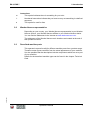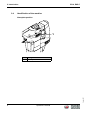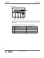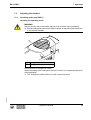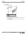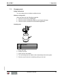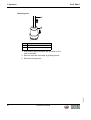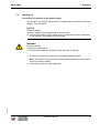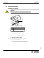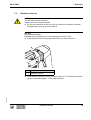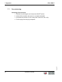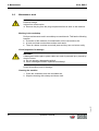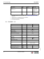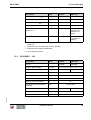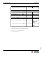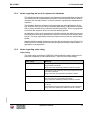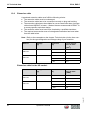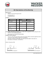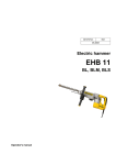
1
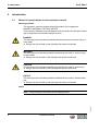
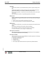
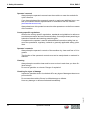
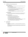
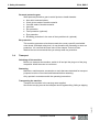
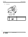
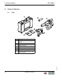
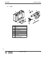
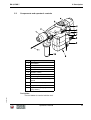
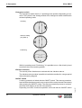
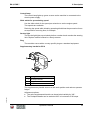
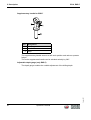
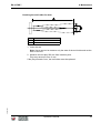
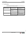
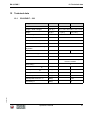
Operator's manual Electric hammer EH 6, EHB 7 November 2008 0217536en / 001 Contents EH 6, EHB 7 Contents Foreword .................................................................................................................... 5 2 Introduction ............................................................................................................... 6 2.1 Means of representation for this operator's manual ........................................... 6 2.2 Wacker Neuson representative .......................................................................... 7 2.3 Described machine parts.................................................................................... 7 2.4 Identification of the machine............................................................................... 8 3 Safety information .................................................................................................. 10 3.1 Principle............................................................................................................ 10 3.2 Qualification of the operating personnel ........................................................... 13 3.3 Protective gear ................................................................................................. 13 3.4 Transport .......................................................................................................... 14 3.5 Operating safety ............................................................................................... 15 3.6 Safety during the operation of hand machines ................................................. 16 3.7 Safety during the operation of electric appliances............................................ 17 3.8 Maintenance ..................................................................................................... 18 3.9 Safety labels ..................................................................................................... 19 4 Scope of delivery .................................................................................................... 20 4.1 EH 6.................................................................................................................. 20 4.2 EHB 7 ............................................................................................................... 21 5 Description .............................................................................................................. 22 5.1 Application ........................................................................................................ 22 5.2 Functionality ..................................................................................................... 22 5.3 Components and operator's controls................................................................ 23 6 Transport ................................................................................................................. 27 Version 001 1 Operator's manual 3 Contents EH 6, EHB 7 7 Operation ................................................................................................................. 28 7.1 Prior to starting the machine ............................................................................ 28 7.2 Adjusting the machine ...................................................................................... 29 7.2.1 Operating mode (only EHB 7) .............................................................. 29 7.2.2 Engine speed........................................................................................ 30 7.2.3 Supplementary handle for EH 6 ........................................................... 31 7.2.4 Supplementary handle for EHB 7 ......................................................... 33 7.2.5 Adjustable depth gauge (only EHB 7) .................................................. 34 7.3 Changing tools ................................................................................................. 35 7.4 Starting up ........................................................................................................ 37 7.5 Operating the machine ..................................................................................... 38 7.6 Vibration reduction ........................................................................................... 39 7.7 Decomissioning ................................................................................................ 40 8 Maintenance ............................................................................................................ 41 8.1 Maintenance schedule ..................................................................................... 41 8.2 Maintenance work ............................................................................................ 42 9 Troubleshooting ...................................................................................................... 44 10 Disposal ................................................................................................................... 45 11 Accessories ............................................................................................................. 46 12 Technical data ......................................................................................................... 47 12.1 EH 6/EHB 7 - 230 ............................................................................................. 47 12.2 EH 6/EHB 7 - 115 ............................................................................................. 48 12.3 EH 6/EHB 7 - 120 ............................................................................................. 49 12.4 Notes regarding the level of exposure to vibrations ......................................... 51 12.5 Notes regarding class rating............................................................................. 51 12.6 Extension cable ................................................................................................ 52 EC Declaration of Conformity................................................................................. 55 Version 001 DIN EN ISO 9001 Certificate .................................................................................... 57 4 Operator's manual 1 Foreword 1 Foreword This operator's manual contains information and procedures for the safe operation and maintenance of your Wacker Neuson machine. In the interest of your own safety and to prevent accidents, you should carefully read through the safety information, familiarize yourself with it and observe it at all times. This operator's manual is not a manual for extensive maintenance and repair work. Such work should be carried out by Wacker Neuson service or authorized specialists. The safety of the operator was one of the most important aspects taken into consideration when this machine was designed. Nevertheless, improper use or incorrect maintenance can pose a risk. Please operate and maintain your Wacker Neuson machine in accordance with the instructions in this operator's manual. Your reward will be troublefree operation and a high degree of availability. Defective machine parts must be replaced immediately! Please contact your Wacker Neuson representative if you have any questions concerning operation or maintenance. All rights reserved, especially reproduction and distribution rights. Copyright 2008 Wacker Construction Equipment AG No part of this publication may be reproduced in any form or by any means, electronic or mechanical, including photocopying, without the expressed written permission of Wacker Neuson. Any type of reproduction, distribution or storage on data media of any type and form not authorized by Wacker Neuson represents an infringement of copyright and will be prosecuted. Version 001 We expressly reserve the right to make technical modifications – even without special notice – which aim at further improving our machines or their safety standards. Operator's manual 5 2 Introduction 2 EH 6, EHB 7 Introduction 2.1 Means of representation for this operator's manual Warning symbols This operator's manual contains safety imformation of the categories: DANGER, WARNING, CAUTION, NOTICE. They should be followed to prevent danger to life and limb of the operator or damage to equipment and exclude improper service. DANGER This warning notice indicates immediate hazards that result in serious injury or even death. f Danger can be avoided by the following the actions mentioned. WARNING This warning notice indicates possible hazards that can result in serious injury or even death. f Danger can be avoided by the following the actions mentioned. CAUTION This warning notice indicates possible hazards that can result in minor injury. f Danger can be avoided by the following the actions mentioned. NOTICE This warning notice indicates possible hazards that can result in material damage. f Danger can be avoided by the following the actions mentioned. Notes Version 001 Note: Complementary information will be displayed here. 6 Operator's manual EH 6, EHB 7 2 Introduction Instructions f This symbol indicates there is something for you to do. 1. Numbered instructions indicate that you have to carry out something in a defined sequence. 2.2 This symbol is used for lists. Wacker Neuson representative Depending on your country, your Wacker Neuson representative is your Wacker Neuson service, your Wacker Neuson affiliate or your Wacker Neuson dealer. You can find the addresses in the Internet at www.wackerneuson.com. The addresses of the Wacker Neuson main locations are located at the end of this operator's manual. 2.3 Described machine parts This operator's manual is valid for different machine parts from a product range. Therefore some figures can differ from the actual appearance of your machine. It is also possible that the descriptions include components which are not a part of your machine. Version 001 Details for the described machine types can be found in the chapter Technical Data. Operator's manual 7 2 Introduction 2.4 EH 6, EHB 7 Identification of the machine Nameplate position Item Nameplate Version 001 1 Designation 8 Operator's manual EH 6, EHB 7 2 Introduction Nameplate data The nameplate lists information that uniquely identifies your machine. This information is needed to order spare parts and when requesting additional technical information. f Enter the information of your machine into the following table: Item Designation Type 2 Construction year 3 Machine no. 4 Version no. 5 Item no. Version 001 1 Your information Operator's manual 9 3 Safety information 3 EH 6, EHB 7 Safety information 3.1 Principle State of the art This machine has been constructed with state-of-the-art technology according to the recognized rules of safety. Nevertheless, when used improperly, dangers to the life and limb of the operator or to third persons or damage to the machine or other materials cannot be excluded. Proper use The machine must only be used for the following purposes: To drill holes with a diameter of maximum 90 mm. For breaking, chiseling, digging, puddling, hammering, ramming and deburring tasks. To process natural and synthetic stone. To process asphalt and any type of masonry and concrete. Its proper use also includes the observance of all instructions contained in this operator's manual as well as complying with the required service and maintenance instructions. Any other use is regarded as improper. Any damage resulting from improper use will void the warranty and the liability on behalf of the manufacturer. The operator assumes full responsibility. Structural modifications Never attempt to modify the machine without the written permission of the manufacturer. To do so will endanger your safety and the safety of other people! In addition, this will void the warranty and the liability on behalf of the manufacturer. Requirements for operation The ability to operate the machine safely requires: Version 001 Proper transport, storage and setup. Careful operation. Careful service and maintenance. 10 Operator's manual EH 6, EHB 7 3 Safety information Operation Operate the machine only as intended and only when in proper working condition. Operate the machine in a safety-conscious manner with all safety devices attached and enabled. Do not modify or disable any safety devices. Before starting operation, check that all control and safety devices are functioning properly. Never operate the machine in a potentially explosive environment. Maintenance Regular maintenance is required in order for the machine to operate properly and reliably over time. Neglected maintenance work can make the machine dangerous to use. Strictly observe the prescribed maintenance intervals. Do not use the machine if it requires maintenance or repairs. Malfunctions If you detect a malfunction, you must shut down and secure the machine immediately. Eliminate the malfunctions that impair safety immediately! Have damaged or defective components replaced immediately! For further information, refer to chapter Troubleshooting. Spare parts, accessories Only use spare parts and accessories from Wacker Neuson. Non-compliance will exempt the manufacturer from all liability. Exclusion of liability Wacker Neuson will refuse to accept liability for injuries to persons or for damage to materials in the following cases: Version 001 Structural modifications. Improper use. Improper handling. Use of spare parts and accessories not produced by Wacker Neuson. Operator's manual 11 3 Safety information EH 6, EHB 7 Operator's manual Always keep the operator's manual near the machine or near the worksite for quick reference. If you have misplaced the operator's manual or require an additional copy, contact your Wacker Neuson representative or download it from the Internet (www.wackerneuson.com). Always hand over this operator's manual to other operators or to the future owner of the machine. Country-specific regulations Observe the country-specific regulations, standards and guidelines in reference to accident prevention and environmental safety, for example those pertaining to hazardous materials and wearing protective gear. Complement the operator's manual with additional instructions taking into account the operational, regulatory, national or generally applicable safety guidelines. Operator's controls Always keep the operator's controls of the machine dry, clean and free of oil or grease. The function of the operator's controls must not be manipulated or rendered ineffective. Cleaning Always keep the machine clean and be sure to clean it each time you have finished using it. Do not use gasoline or solvents. Danger of explosion! Checking for signs of damage Inspect the machine when it is switched off for any signs of damage at least once per work shift. Do not start the machine if there is visible damage or defects. Version 001 Have any damage or defects eliminated immediately. 12 Operator's manual EH 6, EHB 7 3.2 3 Safety information Qualification of the operating personnel Operator qualifications Only trained personnel are permitted to start and operate the machine. The following rules also apply: You are physically and mentally fit. You have received instruction on how to independently use the machine. You have received instruction in the proper use of the machine. You are familiar with required safety devices. You are authorized to start machines and systems in accordance with the standards governing safety. You have been assigned to work on the machine by your company. Incorrect operation Incorrect operation or misuse by untrained personnel can endanger the health and safety of the operator and also cause machine and material damage. Work recommendations Please observe the recommendations below: 3.3 Work only if you are in a good physical condition. Work attentively, particularly as you finish. Do not operate the machine when you are tired. Carry out all work calmly, circumspectly and carefully. Never operate the machine under the influence of alcohol, drugs or medication. This can impair your vision, reactions and your judgment. Work in a manner that does not endanger others. Protective gear Work clothing Clothing should be appropriate, i.e. should be close-fitting but not restrict your movement. Version 001 When on construction sites, do not wear long hair loosely, loose clothing or jewelry including rings. These objects can easily get caught or be drawn in by moving machine parts. Operator's manual 13 3 Safety information EH 6, EHB 7 Personal protective gear Wear personal protective gear to avoid injuries or health hazards: Non-skid, hard-toed shoes. Work gloves made of durable material. Overalls made of durable material. Hard hat. Ear protection. Face protection (optional). Eye protection. Breathing protection in the case of dusty ambient air (optional). Ear protection This machine generates noise that exceeds the country-specific permissible noise levels (individual rating level). It may therefore be necessary to wear ear protection. You can find the exact value in the chapter Technical Data. Wacker Neuson recommends that you always wear ear protection. 3.4 Transport Switching off the machine Before you transport the machine, switch it off and pull the plug out of the plug receptacle. Allow the motor to cool down. Restarting Machines, machine parts, accessories or tools that were detached for transport purposes must be re-mounted and fastened before restarting. Only operate in accordance with the operating instructions. Transporting the machine Transport the machine in the carrying case supplied. Version 001 Secure the carrying case on the transport device against tilting, falling or slipping. 14 Operator's manual EH 6, EHB 7 3.5 3 Safety information Operating safety Work environment Familiarize yourself with your work environment before you start work. This includes e.g. the following items: Obstacles in the work and traffic area. Load-carrying capacity of the ground. The measures needed to cordon off the construction site from public traffic. The measures needed to secure walls and ceilings. Options available in the event of an accident. Safety in the work area When working with the machine especially pay attention to the following points: Electric lines or pipes in work area. Gas lines or water lines in the work area. No one may stay in the room to which a passage is broken through, since there is a danger of injury from falling stones and tools. Checks before starting work Check the following points before beginning work: Condition of tools. Machine settings. Connection value of the machine. Starting the machine Observe the safety information and warning notices located on the machine. Never attempt to switch on a machine that requires maintenance or repairs. Switch on the machine as directed in the operator's manual. Vertical stability Always make sure that you stand firmly when working with the machine. This applies particularly when working on scaffoldings, ladders, etc. Caution with hot parts Do not touch any hot parts such as tools or tool holders during operation or directly afterwards. These parts can become very hot and can cause severe burns. Caution with movable parts Version 001 Keep your hands, feet and loose clothing away from moving or rotating machine parts. Operator's manual 15 3 Safety information EH 6, EHB 7 Caution with toxic materials Some materials may contain toxic chemicals which are released during demolition. Therefore personal protective equipment must be worn to prevent inhalation of and skin contact with work dust. Do not direct towards people Do not direct the machine towards people in the vicinity during oepration. The tool might be flung out and cause serious injuries. Switching off the machine Switch off the engine and pull the plug out of the plug receptacle in the following situations: Before breaks. If you are not using the machine. If you are changing the tool. If you are removing chips or splinters. Before storing the machine, wait until it has completely stopped running. Store the machine or put it down in such a way that it cannot tilt, fall down or slip. Storage location Store the machine after operation at a sealed off, clean and dry location inaccessible to children. 3.6 Safety during the operation of hand machines Safe working with hand machines Secure loose workpieces with suitable methods. While working, as a rule hold the machine on the provided handles with both hands. Always use the supplementary handles included with the machine. While working, hold the machine in such a way that hand injuries are avoided when hitting hard objects. Setting the hand machine down properly Version 001 Set the machine down carefully. Do not drop the machine to the floor or from greater heights. Dropping the machine can cause injuries to other persons or the machine itself can be damaged. 16 Operator's manual EH 6, EHB 7 3 Safety information Safe working with the hammer Keep the tool holder closed during operation. Guide the power cable always from the machine to the rear and keep it away from the working range of the machine. 3.7 Safety during the operation of electric appliances Specific regulations for electrical appliances Observe the safety information provided in the brochure General Safety Rules which is included in the scope of delivery of your machine. Also observe the country-specific regulations, standards and guidelines in reference to accident prevention in connection with electrical equipment and machines. WARNING Read all safety warnings and instructions. Failure to follow the warnings and instructions may result in electric shock, fire and/or serious injury. Save all warnings and instructions for future reference. Electric power supply for electrical appliances of class rating II Note: The rated voltage is indicated on the nameplate of your machine. Only connect the machine to an exterior area shock-proof plug receptacle with a corresponding fault current protective switch. The machine may only be connected to an electric power supply with all machine parts in proper working condition. Take special notice of the following machine parts: Plug. Power cable over the entire length. Electrical appliances of class rating II have a strengthened or double insulation (protective insulation). They have no connection to the grounded conductor. Version 001 Note: Observe the respective national safety regulations! Operator's manual 17 3 Safety information EH 6, EHB 7 Extension cable The machine may only be operated with undamaged extension cables! Only use extension cables with grounded conductor and correct connection of the grounded conductor to the plug and coupling (only for machines of class rating I). Only use extension cables which are suitable for use at construction sites: Average rubber hose H05RN-F or better – Wacker Neuson recommends H07RN-F or a country-specific equivalent design. Immediately replace damaged extension cables (e.g. tears in the sheathing) or loose plugs and couplings. Protecting the power cable Do not use the power cable to pull or lift the machine. Do not unplug the power cable by pulling on the cable. Protect the power cable from heat, oil and sharp edges. If the power cable is damaged or the plug is loose, have it replaced immediately by your Wacker Neuson representative. Protecting from moisture Protect the machine against rain, snow or any other forms of moisture. This could cause damage or malfunctions. 3.8 Maintenance Maintenance work Service and maintenance work must only be carried out to the extent described in these operating instructions. All other procedures must be performed by your Wacker Neuson representative. For further information, refer to chapter Maintenance. Disconnecting the machine from the electric power supply Version 001 Before carrying out service or maintenance work, switch off the generator and pull the plug out of the plug receptacle in order to disconnect the machine from the electric power supply. 18 Operator's manual EH 6, EHB 7 3.9 3 Safety information Safety labels Item Label Description Read the operator's manual. Version 001 1 Operator's manual 19 4 Scope of delivery 4 EH 6, EHB 7 Scope of delivery 4.1 EH 6 Item Designation Carrying case with tool compartments 2 Grease 3 Rotary hammer 4 Supplementary handle 5 Operator's manual 6 Parts book 7 General safety information (without illustration) Version 001 1 20 Operator's manual EH 6, EHB 7 4.2 4 Scope of delivery EHB 7 Item Designation Carrying case with tool compartments 2 Grease 3 Rotary hammer 4 Supplementary handle 5 Adjustable depth gauge 6 Operator's manual 7 Parts book 8 General safety information (without illustration) Version 001 1 Operator's manual 21 5 Description 5 EH 6, EHB 7 Description 5.1 Application EH 6 A wide selection of easily interchangeable tools makes this machine suitable for breaking, chiseling, digging, puddling, hammering, ramming and deburring tasks. The machine is suited for processing natural as well as synthetic stone and asphalt and any type of masonry and concrete. EHB 7 The wide selection of easily replaced tools makes it possible to drill holes with a diameter up to max. 90 mm and are also suitable for breaking, chiseling, digging, puddling, hammering, ramming and deburring. The machine is suited for processing natural as well as synthetic stone and asphalt and any type of masonry and concrete. 5.2 Functionality Principle The machine is a demolition hammer with a pneumatic percussion system. The machine features an additional drilling function depending on model. It is driven by an electric motor. "Chiseling" operating mode The rotary movement of the electric motor is converted into a stroke movement via a transmission and a crank gear while in "Chiseling" operating mode. The piston is moved forwards and backwards by the crank gear, this compresses the air (forward movement) or generates a partial vacuum (backward movement). Due to change in pressure the percussion piston is moved forward and backwards (air cushion percussion system) and hits the tool. While in "Chiseling" operating mode, the drill drive is uncoupled via the safety clutch and the tool holder bushing is fixed in place to prevent turning in the tool holder. "Hammer drilling" operating mode Version 001 While in "Hammer drilling" operating mode, the rotational movement of the motor is transferred to the drive shaft of the drill drive via a clutch. The drive shaft uses gear wheels to turn the tool holder bushing in the tool holder. 22 Operator's manual EH 6, EHB 7 5.3 5 Description Components and operator's controls Item Designation 1 Tool holder 2 Ventilation slot 3 Changeover switch 4 Vibration reduction 5 ON/OFF switch 6 Control lamp 7 Service light 8 Slide switch for pre-selecting speed 9 Power cable with plug 10 Supplementary handle 11 Adjustable depth gauge (only EHB 7) Tool holder Version 001 The tool holder is used to hold the tool. Operator's manual 23 5 Description EH 6, EHB 7 Changeover switch The changeover switch has 2 or 3 operating mode positions depending on machine. The symbol in the viewing window of the changeover switch identifies the selected operating mode. Chiseling Hammer drilling (only EHB 7) Positioning While in operating mode "Positioning," it is possible to turn a flat chisel by hand to achieve the correct working position. Vibration reduction The severity of the vibrations are reduced with the vibration reducer. The vibration reducer makes it possible to handle the machine for a longer period without becoming fatigued. ON/OFF switch Depending on model, continuous operation can be set with the ON/OFF switch. 24 Operator's manual Version 001 A start-up protection is linked with the ON/OFF switch. This start-up protection has the effect that the percussion rate or speed of the rotary hammer rises slowly after pressing the ON/OFF switch. The start-up protection prevents or reduces the chisel from slipping or the drill from jamming. EH 6, EHB 7 5 Description Control lamp The control lamp lights up green as soon as the machine is connected to the electric power supply. Slide switch for pre-selecting speed Use the slide switch for the speed pre-selection to set the engine speed. Two speeds are available. Reducing the speed while chiseling operating diminishes the percussion forces as required for removing tiles, for example. Service light The service light lights up red shortly before a carbon brush reaches the wearing limit. Replace carbon brushes in a timely manner. Plug The machine comes with a country-specific plug as a standard equipment. Supplementary handle for EH 6 Item Designation 1 D-shaped handle 2 Toggle nut 3 Strap The supplementary handle ensures a safe work position and reduces operator fatigue. Adjustment options: Version 001 The entire supplemental handle can be swiveled variably by 360°. The D-shaped handle can be swiveled 360° in increments of 20 steps. Operator's manual 25 5 Description EH 6, EHB 7 Supplementary handle for EHB 7 Item Designation 1 Clamping piece 2 Radial handle 3 Strap The supplementary handle ensures a safe work position and reduces operator fatigue. The entire supplemental handle can be swiveled variably by 360°. Adjustable depth gauge (only EHB 7) Version 001 The depth gauge enables the variable adjustment of the drilling depth. 26 Operator's manual EH 6, EHB 7 6 6 Transport Transport Transporting the machine The machine must be transported in the carrying case supplied. 1. Pull the mains plug from the socket. 2. Remove tool. 3. Remove supplementary handle. 4. Place the machine in the carrying case. 5. Wind up the power cable and place in the carrying case. Note: Do not kink the power cable! 6. Store the tools in the carrying case. 7. Place the carrying case on or into a suitable means of transport. Version 001 8. Secure the carrying case against falling over and down or sliding. Operator's manual 27 7 Operation 7 EH 6, EHB 7 Operation WARNING Improper handling can result in injury or serious material damage. f Read and follow all safety instructions of this operator's manual, see chapter Safety information. WARNING Electrical voltage. Injuries from electrocution. f Remove the plug from the plug receptacle before all work on the machine. 7.1 Prior to starting the machine After unpacking, the machine is ready for operation. Checking the machine f Check the machine and all components for damages. Checking the mains f Check if mains or power distribution on the construction site have the correct operating voltage (see nameplate of the machine or chapter Technical Data). Version 001 f Check if mains or power distribution on the constructions site are protected in accordance with current standards and regulations. 28 Operator's manual EH 6, EHB 7 7 Operation 7.2 Adjusting the machine 7.2.1 Operating mode (only EHB 7) Selecting the operating mode WARNING Danger of injury with uncontrolled start up of the machine during switching. f Actuate changeover switch only when machine is inactivated and has come to a complete standstill. Item 1 Designation Changeover switch Check position of changeover switch. Adjust the setting of the changeover switch if it does not correspond with the desired application: Version 001 f Turn changeover switch half a turn until it snaps into place. Operator's manual 29 7 Operation 7.2.2 EH 6, EHB 7 Engine speed Setting the engine speed Item 1 Designation Slide switch for pre-selecting speed Use the slide switch to adjust the engine speed: f Press slide switch for pre-selecting the speed towards rear (small symbol) to reduce engine speed. Version 001 f Press slide switch for pre-selecting the speed towards front (large symbol) to increase engine speed. 30 Operator's manual EH 6, EHB 7 7.2.3 7 Operation Supplementary handle for EH 6 Only operate the machine with the supplementary handle. Swiveling the supplementary handle Item 1 Designation Toggle nut 1. Loosen the toggle nut by turning counterclockwise until the supplementary handle can be swiveled. 2. Swivel supplementary handle to desired position. Version 001 3. Tighten the toggle nut by turning clockwise. Operator's manual 31 7 Operation EH 6, EHB 7 Swiveling the D-shaped handle Item Designation 1 D-shaped handle 2 Toggle nut 3 Gearing 1. Loosen the toggle nut by turning counterclockwise until the gearing is loosened. 2. Swivel D-shaped handle to desired position and allow gearing to snap into place. Version 001 3. Tighten the toggle nut by turning clockwise. 32 Operator's manual EH 6, EHB 7 7.2.4 7 Operation Supplementary handle for EHB 7 Only operate the machine with the supplementary handle. Swiveling the supplementary handle Item 1 Designation Radial handle 1. Loosen the radial handle by turning counterclockwise until the supplementary handle can be swiveled. 2. Swivel supplementary handle to desired position. Version 001 3. Tighten the radial handle by turning clockwise. Operator's manual 33 7 Operation 7.2.5 EH 6, EHB 7 Adjustable depth gauge (only EHB 7) Adjusting the depth gauge NOTICE Slipping of the adjustable depth gauge can result in incorrect borehole depths. f Always insert adjustable depth gauge into clamp with the grooved side pointing up. Item Designation 1 Adjustable depth gauge 2 Clamping piece 1. Press clamping piece. 2. Adjust depth gauge as needed by pulling out or pushing in. Version 001 3. Release clamping piece. 34 Operator's manual EH 6, EHB 7 7.3 7 Operation Changing tools Safety instructions You can change the tool without additional tools. Notes on using tools Only use tools with the following properties: The tool end must be undamaged. The tool must be sufficiently sharp to avoid impact damage. The tool must be suitable for the intended application. Inserting tool Item Designation 1 Tool 2 Tool holder 1. Clean tool end. 2. Grease tool end. 3. Insert tool into tool holder. 4. Turn tool and press into holder until automatically locked into place. Version 001 5. Check to see if the tool is locked by pulling on the tool. Operator's manual 35 7 Operation EH 6, EHB 7 Removing tool Item Designation 1 Tool 2 Locking sleeve 1. Slide locking sleeve towards rear and hold on to it. Lock is released. 2. Remove tool from tool holder by pulling forward. Version 001 3. Release locking sleeve. 36 Operator's manual EH 6, EHB 7 7.4 7 Operation Starting up Connecting the machine to the power supply The machine may only be connected to AC single phase, connection values see chapter Technical Data. NOTICE Electrical voltage. Incorrect voltage can cause damage on the machine. f Check if the voltage of the current source corresponds with the information of the machine, see chapter Technical Data. WARNING Electrical voltage. Injuries from electrocution. f Check power cable and extension cable for signs of damage. 1. If required, connect the machine to a permitted extension cable. Note: See chapter Technical data for the permitted lengths and cross-section areas of extension cables. Version 001 2. Insert the plug into the plug receptacle. Operator's manual 37 7 Operation 7.5 EH 6, EHB 7 Operating the machine Switching on the machine WARNING Injuries from insufficiently guided or uncontrolled machine. f Always hold machine with both hands and stand firmly. Item Designation 1 Lock button 2 ON/OFF switch 1. Set machine at working position. 2. Press the ON/OFF switch. Activating continuous operation (only EH 6) 1. Press and hold ON/OFF switch. 2. Additionally press lock button. Deactivating continuous operation (only EH 6) f Press the ON/OFF switch. Version 001 The lock button is released and in up position. 38 Operator's manual EH 6, EHB 7 7.6 7 Operation Vibration reduction CAUTION Too little spring travel at handle. Injuries due to too severe kickback. f Do not press machine all the way up to the stop of the vibration reduction and against the area you wish to work on. NOTICE Uncontrolled kickback. Damages due to slipping tool or tool breaking to the left or right. f Press machine more heavily against the area you wish to work on. Item 1 Designation Vibration reduction Version 001 f Press machine against the area you wish to work on. The vibration reduction can be compressed approx. to the middle position. Operator's manual 39 7 Operation 7.7 EH 6, EHB 7 Decomissioning Switching off the machine 1. Release or press again and release the ON/OFF switch. 2. Wait until the machine has come to a complete standstill. 3. Set down the machine in such a way that it cannot tilt, fall or slip. Version 001 4. Pull the plug from the plug receptacle. 40 Operator's manual EH 6, EHB 7 8 8 Maintenance Maintenance WARNING Improper handling can result in injury or serious material damage. f Read and follow all safety instructions of this operator's manual, see chapter Safety information. 8.1 Maintenance schedule Task Daily before operation Check power cable for perfect condition – if power cable is defective, have it replaced. * Visual inspection of all parts for damage. Clean the machine. Check the tool end and cutting edges – if required, sharpen, reforge or replace. Check tool holder for wear – have it changed, if necessary. * * Monthly Have your Wacker Neuson contact partner carry out these tasks. Version 001 Note: Take the machine to your Wacker Neuson contact partner for servicing when the red service light lights up. Operator's manual 41 8 Maintenance 8.2 EH 6, EHB 7 Maintenance work WARNING Electrical voltage. Injuries from electrocution. f Remove the plug from the plug receptacle before all work on the machine. Working in the workshop Perform maintenance work in a workshop on a workbench. This has the following benefits: Protection of the machine of contamination on the construction site. A level and clean work surface makes work easier. There is a better overview over small parts and they are not lost as easily. Visual inspection for damage WARNING A damaged machine part or power cable can result in personal injury caused by electric current. f Do not operate a damaged machine! f Have a damaged machine repaired immediately! Check all machine parts for damage. Cleaning the machine 1. Clean the ventilation slots with a suitable tool. Version 001 2. Wipe the housing with a damp and clean cloth. 42 Operator's manual EH 6, EHB 7 8 Maintenance Checking the tool holder for wear Item Value A 200 mm B Max. 6 mm 1. Insert the tool. Note: Use a new tool to measure only the wear of the tool holder and not the wear of the tool. 2. Measure the tool play 200 mm from insertion point. Play may amount to max. 6 mm. Version 001 If the play exceeds 6 mm, the tool holder must be replaced. Operator's manual 43 9 Troubleshooting 9 EH 6, EHB 7 Troubleshooting Please refer to the following table if the machine does not work properly. It contains potential faults, their causes and remedies. Malfunction Cause Remedy Machine not in operation Power cable interrupted. Check power cable, have it replaced if defective. * Rotor defective. Have rotor replaced. * Ice formation due to very low temperatures. Allow machine to warm up in warm environment (e.g. heated rooms). Seizing of moveable parts. Have defective components replaced. * Too much borer dust in borehole. Pull drill bit out off borehole and remove dust from drill bit. Interfering reinforcing steel. Redrill borehole. Blocked percussion system Drill is jammed (only EHB 7) Have your Wacker Neuson contact partner carry out these tasks. Version 001 * 44 Operator's manual EH 6, EHB 7 10 Disposal 10 Disposal Dispose the machine and packaging through environmentally friendly recycling. During disposal observe the regional rules and regulations, e.g. the European Directive for obsolete electrical and electronic devices. Version 001 Do not dispose of the machine in household rubbish. It must be disposed of separately. Operator's manual 45 11 Accessories EH 6, EHB 7 11 Accessories There is a wide range of accessories available for the machine. Version 001 For more information on the individual accessories, visit the following website: www.wackerneuson.com. 46 Operator's manual EH 6, EHB 7 12 Technical data 12 Technical data 12.1 EH 6/EHB 7 - 230 Designation Unit Item no. EH 6 M EHB 7 M 0610304 0610303 Length x Width x Height mm (in) 473 x 109 x 293 (18.6 x 4.3 x 11.5) Weight kg (lb) 7.1 (15.7) Rated voltage V 220-240 1~ Rated frequency Hz 50 Rated power consumption W 1,300 Rated current consumption A 7 Percussion rate electronically adjustable rpm Drill speed rpm Single stroke energy J 7.3 (16.1) 2,200-2,850 - 450 12 Tool holder SDS-max Drive Universal electric motor with protective insulation Class rating * II dB(A) 91 - Sound power level LWA *** dB(A) 101 - Sound pressure level LPA **** dB(A) - 96 Uncertainty K dB(A) - 3 Sound power level LWA **** dB(A) - 107 Uncertainty K dB(A) - 3 Version 001 Sound pressure level LPA ** Operator's manual 47 12 Technical data EH 6, EHB 7 Designation Unit EH 6 M EHB 7 M Total vibration value of the acceleration ahv **** m/s2 11.5 9 (chiseling) 13 (hammer drilling in concrete) Uncertainty K m/s2 1.9 1.9 (chiseling) 1.5 (hammer drilling) * According to DIN EN 61140, description see 12.5 Notes regarding class rating (page 51). ** Determined acc. to 2000/14/EC at ear of operator. *** Determined according to 2000/14/EC. **** According to EN 60745. 12.2 EH 6/EHB 7 - 115 Designation Unit Item no. EH 6 M EHB 7 M 0610306 0610307 Length x Width x Height mm (in) 473 x 109 x 293 (18.6 x 4.3 x 11.5) Weight kg (lb) 7.1 (15.7) Rated voltage V 110-120 1~ Rated frequency Hz 50 Rated power consumption W 1,300 Rated current consumption A 14 Percussion rate electronically adjustable rpm Drill speed rpm Single stroke energy J 7.3 (16.1) 2,200-2,850 - 450 12 Tool holder SDS-max Drive Universal electric motor with protective insulation Class rating * II dB(A) 91 - Sound power level LWA *** dB(A) 101 Version 001 Sound pressure level LPA ** 48 Operator's manual EH 6, EHB 7 12 Technical data Designation Unit EH 6 M EHB 7 M Sound pressure level LPA **** dB(A) - 96 Uncertainty K dB(A) - 3 Sound power level LWA **** dB(A) - 107 Uncertainty K dB(A) - 3 Total vibration value of the acceleration ahv **** m/s2 11.5 9 (chiseling) 13 (hammer drilling in concrete) Uncertainty K m/s2 1.9 1.9 (chiseling) 1.5 (hammer drilling) * According to DIN EN 61140, description see 12.5 Notes regarding class rating (page 51). ** Determined acc. to 2000/14/EC at ear of operator. *** Determined according to 2000/14/EC. **** According to EN 60745. 12.3 EH 6/EHB 7 - 120 Designation Unit Item no. EH 6 M EHB 7 M 0610308 0610309 Length x Width x Height mm (in) 473 x 109 x 293 (18.6 x 4.3 x 11.5) Weight kg (lb) 7.1 (15.7) Rated voltage V 120 1~ Rated frequency Hz 60 Rated power consumption W 1,300 Rated current consumption A 14 Percussion rate electronically adjustable rpm Drill speed rpm Single stroke energy J 2,200-2,850 - 450 12 SDS-max Version 001 Tool holder 7.3 (16.1) Operator's manual 49 12 Technical data EH 6, EHB 7 Designation Unit EH 6 M Drive EHB 7 M Universal electric motor with protective insulation Class rating * II Sound pressure level LPA ** dB(A) 91 - Sound power level LWA *** dB(A) 101 - Sound pressure level LPA **** dB(A) - 96 Uncertainty K dB(A) - 3 Sound power level LWA **** dB(A) - 107 Uncertainty K dB(A) - 3 Total vibration value of the acceleration ahv **** m/s2 11.5 9 (chiseling) 13 (hammer drilling in concrete) Uncertainty K m/s2 1.9 1.9 (chiseling) 1.5 (hammer drilling) * According to DIN EN 61140, description see 12.5 Notes regarding class rating (page 51). ** Determined acc. to 2000/14/EC at ear of operator. *** Determined according to 2000/14/EC. Version 001 **** According to EN 60745. 50 Operator's manual EH 6, EHB 7 12.4 12 Technical data Notes regarding the level of exposure to vibrations The vibration emission level given in this Operator´s manual has been measured in accordance with a standardised test given in EN 60745 and may be used to compare one tool with another. It may be used for a preliminary assessment of exposure. The declared vibration emission level represents the main applications of the tool. However if the tool is used for different applications, with different accessories or poorly maintained, the vibration emission may differ. This may significantly increase the exposure level over the total working period. An estimation of the level of exposure to vibration should also take into account the times when the tool is switched off or when it is running but not actually doing the job. This may significantly reduce the exposure level over the total working period. Identify additional safety measures to protect the operator from the effects of vibration such as: maintain the tool and the accessories, keep the hands warm, organisation of work patterns. 12.5 Notes regarding class rating Class rating The class rating according to DIN EN 61140 specifies the safety measures for electrical equipment to avoid electrocution. There are four class ratings: Meaning 0 No special protection apart from the basic insulation. No grounded conductor. Plug connection without grounded conductor contact. I Connection of all conductive housing components to the grounded conductor. Plug connection with grounded conductor contact. II Reinforced or double insulation (protective insulation). No connection to the grounded conductor. Plug connection without grounded conductor contact. III Equipment is operated on protective low voltage (< 50 V). Connection to the grounded conductor is not necessary. Plug connection without grounded conductor contact. Version 001 Class rating Operator's manual 51 12 Technical data 12.6 EH 6, EHB 7 Extension cable A permitted extension cable must fulfill the following criteria: The extension cable must be undamaged. The extension cable has to be connected correctly on plug and bushing. The extension cable has to be suitable for use at construction sites: Average rubber hose H05RN-F or better – Wacker Neuson recommends H07RN-F or a country-specific equivalent design. The extension cable must have been checked by a qualified electrician. The required cross-section area of a designated extension has been taken from the table below. Note: Refer to the nameplate or the chapter Technical data (via the item number) for the type designation and voltage rating of your machine. Machine Voltage [V] Extension [m] Cross-section area of cable [mm2] EH 6 M EHB 7 M 230 < 86 1.5 < 142 2.5 EH 6 M EHB 7 M 110-120 < 22 1.5 < 37 2.5 < 59 4.0 Extension cable for the US market: Voltage [V] Extension [ft] Cross-section area of cable [AWG] EH 6 M EHB 7 M 230 < 246 16 < 390 14 EH 6 M EHB 7 M 110-120 < 102 14 < 161 12 < 253 10 Version 001 Machine 52 Operator's manual EH 6, EHB 7 12 Technical data Example You utilize an EHB 7 M/230 and want to use an extension cable with a length of 50 m (164 ft). The machine has an input voltage of 230 V. Version 001 According to the table, the extension cable must feature a cross-section area of 1.5 mm2 (AWG 16). Operator's manual 53 EH 6, EHB 7 Version 001 12 Technical data 54 Operator's manual EC Declaration of Conformity Manufacturer Wacker Construction Equipment AG Preußenstraße 41 D-80809 München Product Type EH 6 M Product type EHB 7 M Demolition/rotary hammer Item number 0610304, 0610306, 0610308 0610303, 0610307, 0610309 Weight [kg] 7.1 7.3 Measured sound power level dB(A) 101 — Guaranteed sound power level dB(A) 104 — Conformity assessment procedure acc. to 2000/14/EC, Appendix VI at following test center: VDE Prüf- und Zertifizierungsinstitut Merianstraße 28, D-63069 Offenbach/Main Guidelines and standards This is to certify that this product meets and complies with the relevant regulations and requirements of the following guidelines and standards: 98/37/EC, EN 60745, 2000/14/EC (only EH 6 M), 2004/108/EC, EN 61000-3-2, EN 61000-3-3, EN 55014-1, EN 55014-2 Munich, December 2008 Franz Beierlein Head of product management Dr. Michael Fischer Head of Research and Development www.wackerneuson.com DIN EN ISO 9001 Certificate Prüf- und Zertifizierungsinstitut VERBAND DER ELEKTROTECHNIK ELEKTRONIK INFORMATIONSTECHNIK e.V. CERTIFICATE Registration-Number: 6236/QM/06.97 This is to certify that the company Wacker Construction Equipment AG Wacker-Werke GmbH & Co. KG at the following locations Head Office Munich Preußenstraße 41 80809 Munich Production plant Reichertshofen Karlsfeld logistics centre Sales regions with all branches all over Germany has implemented and maintains a Qality Management System for the following scope: Machine manufacture Construction machines This Q System complies with the requirements of DIN EN ISO 9001:2000 and the requirements of the German and international Road Traffic Act. This Certificate is valid until 2009-06-05. VDE Testing and Certification Institute Certification Date: 2006-05-30 63069 Offenbach, Merianstraße 28 Telefon: +49 (0) 69 83 06-0, Telefax: +49 (0) 69 83 06-555 E-Mail: [email protected], http://www.vde-institut.com The VDE Testing and Certification Institute is accredited by DAR Accreditation Bodies according to DIN EN ISO 17020 and DIN EN ISO 45012 and notified in the EU under ID.No. 0366. TGA-ZM-09-92-00 KBA-ZM-A 00021-97 Wacker Construction Equipment AG, Preußenstraße 41, 80809 München – Deutschland – Tel.: +49-(0)89-354 02-0 – Fax: +49-(0)89-354 02-390 Wacker Corporation – P.O. Box 9007 – Menomonee Falls, WI 53052-9007 – USA – Tel.: +1(1)262-255-0500 – Fax: +1(1)262-255-0550 – Support: 800-770-0957 Wacker Machinery (HK) Ltd.– Skyline Tower, Suite 2303, 23/F – 39 Wang Kwong Road, Kowloon Bay – Hong Kong – Tel.: +852-3188-5506, Fax: +852-2406-6021