1
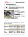
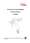
Assembly Instructions Self-Piercing Rivet Tool ERT/LS/LSC Please read the assembly instructions before any operation! © Emhart Teknologies TUCKER GmbH Max-Eyth-Straße 1 D-35394 Gießen Tel.: +49 (0) 641 405 0 Fax.: +49 (0) 641 405-383 E-Mail: [email protected] Internet: www.tucker.de Translation of the original assembly instructions MTA ERT LS LSC 01 2 Self-Piercing Rivet Tool ERT/LS/LSC Table of Contents Table of Contents: 1 2 General Information....................................................................................................5 1.1 Information Regarding the Assembly Instructions.............................................5 1.2 Limitation of Liability..........................................................................................5 1.3 Symbol Legend .................................................................................................6 1.4 Copyright Protection..........................................................................................7 1.5 Replacement Parts............................................................................................7 1.6 Guarantee Instructions......................................................................................8 1.7 After Sales Service............................................................................................8 1.8 Remark to the Declaration of Incorporation ......................................................8 Safety .........................................................................................................................9 2.1 Responsibility of the Operating Company.........................................................9 2.2 Personnel Requisition .....................................................................................10 2.3 3 4 2.2.1 Qualification ........................................................................................10 2.2.2 Trespassers ........................................................................................11 2.2.3 Instruction............................................................................................11 Intended Use...................................................................................................12 2.3.1 Self-Piercing Rivet Tool ERT ..............................................................12 2.3.2 Linear Slide LS....................................................................................13 2.3.3 Linear Slide Control LSC.....................................................................14 2.4 Personal Protective Equipment.......................................................................15 2.5 Special Risks...................................................................................................16 2.6 Safety Installations ..........................................................................................17 Technical Data .........................................................................................................18 3.1 General Specifications Rivet Tool ERT 80......................................................18 3.2 General Specifications Rivet Tool ERT 40......................................................19 3.3 General Specifications Linear Slide ................................................................20 3.4 General Specifications Linear Slide Control....................................................20 3.5 Equipment Fuses ............................................................................................21 3.6 Accessories.....................................................................................................21 3.7 Tool List Self-Piercing Rivet Tool ....................................................................22 3.8 Fastening Torques for Metric Screws .............................................................24 3.9 Table of Control Cables/Hoses .......................................................................24 System Components ................................................................................................25 4.1 ERT 80 Tool with Linear Slide.........................................................................25 4.2 ERT 40 Tool with Linear Slide.........................................................................26 4.3 Linear Slide Control.........................................................................................28 4.4 Operation Sequence .......................................................................................29 4.4.1 Rivet Spindle Propulsion Concept.......................................................29 3 Self-Piercing Rivet Tool ERT/LS/LSC Table of Content 5 6 7 4.4.2 Assembly Sequence ........................................................................... 30 4.4.3 Tool Changer ...................................................................................... 36 Connecting ERT Tool............................................................................................... 37 5.1 Connecting the ERT Tool to the ERC Control Unit ......................................... 38 5.2 Connecting Rivet Spindle to the Feeder ......................................................... 39 5.2.1 Connecting Feed Tube to the Rivet Spindle ....................................... 39 5.2.2 Connecting Feed Tube to Feeder....................................................... 40 5.3 Connecting the Linear Slide Control to the Feeder......................................... 41 5.4 Connecting the Linear Slide and the Linear Slide Control .............................. 42 5.5 Compressed Air Supply for the Linear Slide Control ...................................... 43 5.6 Setting the Linear Slide Proximity Switch ....................................................... 44 5.7 Setting Riveting Parameter............................................................................. 45 5.8 Adjustment Travel........................................................................................... 46 Transport, Packaging and Storing ........................................................................... 47 6.1 Security Advice for the Transport ................................................................... 47 6.2 Transport Check ............................................................................................. 47 6.3 Terms and Conditions for Overseas Transport............................................... 48 6.4 Packaging ....................................................................................................... 49 6.5 Storing ............................................................................................................ 49 Maintenance and Cleaning ...................................................................................... 50 7.1 Safety.............................................................................................................. 50 7.2 Maintenance and Cleaning Schedule ............................................................. 50 7.3 Emptying the Maintenance Unit...................................................................... 55 7.4 Lubricating the ERT 80 Riveting Spindle ........................................................ 55 7.5 Lubricating the ERT 40 Riveting Spindle ........................................................ 56 7.5.1 8 7.6 Lubricating the Linear Slide ............................................................................ 58 7.7 Cleaning the Receiver and Upper Riveting Die .............................................. 59 7.8 Changing the Upper Riveting Die ................................................................... 59 Disposal ................................................................................................................... 61 Appendix: 4 Lubricating Sequence ERT................................................................. 57 Declaration of Incorporation Self-Piercing Rivet Tool ERT/LS/LSC General Information 1 General Information 1.1 Information Regarding the Assembly Instructions These assembly instructions contain important information regarding the handling of this device. The compliance with all security advisories and operation instructions is a precondition for a safe operation. Furthermore the local accident prevention regulations and the general safety regulations effective for the application area of the device have to be observed. Please read the assembly instructions carefully before any operation! It is a part of the product and has to be stored in an accessible location in the direct vicinity of the device for use by the appropriate personnel. 1.2 Limitation of Liability All instructions and information in these assembly instructions have been compiled in consideration of the valid standards and regulations, the state of the art as well as our experience of many years. The manufacturer assumes no liability for damages due to: Non-observance of the assembly instructions. Not intended use. Employment of unskilled personnel. Arbitrary rebuilding. Technical modifications. Use of non-licensed replacement parts. On special design, on demands of additional order options or due to latest technical modifications the actual shipment may differ from the explanations and expositions described here. Effective are the obligations agreed in the supply contract, the general terms and conditions as well as the delivery conditions of the supplier and the legal regulations valid to the time of conclusion of the contract. Technical modifications within the improvement of the usage properties and the further development are reserved. 5 Self-Piercing Rivet Tool ERT/LS/LSC General Information 1.3 Symbol Legend Warning notices The warning notices in this operation manual are indicated by symbols. The notes commence with a signal word which expresses the extent of the danger. Observe the notes and act with caution to avoid accidents and damage to persons and property. DANGER! … points to a directly dangerous situation which can lead to death or severe injuries if it is not avoided. WARNING! … points to a possibly dangerous situation which can lead to death or severe injuries if it is not avoided. CAUTION! … points to a possibly dangerous situation which can lead to slight injuries if it is not avoided. ! CAUTION! … points to a possibly dangerous situation which can lead to damage of property if it is not avoided. Tips and recommendations NOTE! … highlights useful tips and recommendations as well as information for an efficient and failure-free operation. 6 Self-Piercing Rivet Tool ERT/LS/LSC General Information Special security advisories In order to draw attention to special dangers, the following symbols are used in connection with security advisories: DANGER! Danger to life by electric current! … indicates perilous situations by electric current. Disregarding of the security advisories can lead to severe injuries or death. The operations which need to be carried out may only be executed by electronic technicians. WARNING! RISK OF HAND INJURY! Keep hands away from areas marked with this warning sign. There is a risk that hands could be squeezed, pulled in or injured otherwise. 1.4 Copyright Protection This instruction is protected by copyright and only intended for internal purposes. The provision of the instruction to a third party, duplications in all kinds and forms also in extracts - as well as the utilisation and/or communication of the content are, aside from internal purposes, not permitted without a written authorization of the manufacturer. Non-compliances obligate to damages. Further claims remain reserved. 1.5 Replacement Parts WARNING! Safety risk due to false replacement parts! False or defective replacement parts can affect the safety as well as lead to damages, malfunctions or total breakdown. Therefore: - Use original TUCKER replacement parts. Purchase replacement parts via licensed dealer or directly at manufacturer. Address see page 2. 7 Self-Piercing Rivet Tool ERT/LS/LSC General Information 1.6 Guarantee Instructions For material and manufacturing faults, the guarantee period for this self-piercing riveting tool amounts to 1 year from delivery date on. Excluded from this is damage that is caused by accident or by incorrect handling. The guarantee covers free-of-charge replacement of the faulty component. In this connection, liability for consequential damage is excluded. Guarantee void in case of attempts to repair by personnel that has not been trained by the manufacturer and/or when using spare parts that TUCKER has not approved of. In the event of a defect the non-conforming appliance must be sent to the next TUCKER agent or directly to the manufacturer. The guarantee claim lapses when attempts at repair are carried out by unauthorised or unqualified persons. In the event of a defect the non-conforming appliance must be sent to the next TUCKER agent or directly to the manufacturer. For further information concerning national representation, our customer service is at your disposal. The corresponding contact data can be found on page 2. 1.7 After Sales Service Our service department is available for technical support. Information about the responsible contact person is available via telephone, fax, EMail or anytime via the Internet, please see manufacturer address on page 2. Furthermore, our employees are constantly interested in new information and experiences that result from the single applications and could be helpful for improving our products. 1.8 Remark to the Declaration of Incorporation Note! A declaration of incorporation for the inc of an incomplete machine with the corresponding details according to the EC machinery directive 2006/42/EG, appendix II, paragraph B is attached to the documents. 8 Self-Piercing Rivet Tool ERT/LS/LSC Safety 2 Safety This paragraph gives a review about all important safety aspects for an optimal protect of the personnel as well as for the safe and failure-free operation. Disregard of the operating instructions and security advices mentioned in this manual could lead to serious dangers. 2.1 Responsibility of the Operating Company The stud feeding unit is used industrially. Therefore the operating company of the unit is liable to the legal obligations of operational safety. In addition to the operational safety advisories in these assembly instructions the safety-, accident prevention- and environmental regulations in force for the area of application need to be observed. Please consider particularly the following: The operating company has to inform himself about the valid industrial safety regulations and determine additional dangers in an assessment of hazards which occur by the special working conditions on the site of the unit. He has to implement these for the operation of the unit in the form of operating instructions. The operating company has to verify that the operating instructions are state of the art during the complete operating time of the unit. If necessary, the operating company is to adjust the operating instructions to the valid rules and regulations. The operating company has to manage and determine the responsibilities for installation, operation, maintenance and cleaning in an explicit manner. The operating company has to ensure that all employees dealing with the unit have read and understood this manual. Moreover, the operating company has to train the operating personnel in regular intervals and has to provide information on possible dangers. The operating company has to provide the personnel with the required protective equipment. 9 Self-Piercing Rivet Tool ERT/LS/LSC Safety 2.2 Personnel Requisition 2.2.1 Qualification WARNING! Risk of injury on insufficient qualification! Improper handling can lead to serious damage to persons and property. Therefore: - All activities are to be carried out by skilled personnel only! The following qualifications for different areas of operations are named in the assembly instructions: Instructed person Has been informed about the tasks assigned and possible dangers of improper execution of an instruction by the operating company. Qualified personnel Qualified personnel are able to carry out the assigned tasks due to their qualified training, knowledge and job experience. In addition, the personnel are able to recognize and avoid possible dangers on their own. Electrician The electrician is able to carry out activities on electric units due to his qualified training, knowledge and job experience. In addition, he is able to recognize and avoid possible dangers on his own. The electrician has been trained for the special site he is working on and knows about the relevant rules and regulations. Only persons who can be expected to carry out their work in a reliable manner can be accepted as personnel. Persons whose reactivity is influenced, e.g. by drugs, alcohol or medicaments, are not admitted. 10 Please consider the regulations at site specific to age and profession when choosing personnel! Self-Piercing Rivet Tool ERT/LS/LSC Safety 2.2.2 Trespassers WARNING! Danger for trespassers! Trespassers who do not fulfil the requirements mentioned in this document do not know about the dangers of this working area. Therefore: - Keep trespassers away from the working area. - When in doubt, approach persons and banish them from the working area. - Interrupt your work as long as there are trespassers within the working area. 2.2.3 Instruction The personnel have to be instructed regularly by the operating company. For a better traceability the implementation of the instruction should be recorded. Date Name Kind of instruction Instruction Signature carried out by 11 Self-Piercing Rivet Tool ERT/LS/LSC Safety 2.3 Intended Use 2.3.1 Self-Piercing Rivet Tool ERT The Self-Piercing Rivet Tool ERT was designed exclusively for the intended use mentioned in this manual. The ERT Tool is intended to mount self-piercing rivets in industrial and commercial areas and only for application in premises. The ERT tool has been designed for automatic operation in robots, semiautomatic operation and manual operation. Intended use also includes observing all the symbols and information in the assembly instructions. Any excess of the intended use or different use of the device is considered as misuse and can lead to dangerous situations. WARNING! Risk by not intended use! Every not intended use and/or different use can lead to dangerous situations. Therefore: - The ERT tool may only in conjunction with the system components specified in the assembly instructions. - Do not operate the ERT tool in explosive areas. - Do not operate the ERT tool in damp rooms. Claims of any kind because of damages due to not intended use are excluded. 12 Self-Piercing Rivet Tool ERT/LS/LSC Safety 2.3.2 Linear Slide LS The linear slide LS was designed exclusively for the intended use mentioned in this manual. The linear slide is intended to mount self-piercing rivets in industrial and commercial areas and only for application in premises. The linear slide can only operate in conjunction with a linear slide control. The linear slide has been designed for automatic operation in robots, semiautomatic operation and manual operation. Intended use also includes observing all the symbols and information in the assembly instructions. Any excess of the intended use or different use of the device is considered as misuse and can lead to dangerous situations. WARNING! Risk by not intended use! Every not intended use and/or different use can lead to dangerous situations. Therefore: - The linear slide may only in conjunction with the system components specified in the assembly instructions. - Do not operate the linear slide in explosive areas. - Do not operate the linear slide in damp rooms. Claims of any kind because of damages due to not intended use are excluded. 13 Self-Piercing Rivet Tool ERT/LS/LSC Safety 2.3.3 Linear Slide Control LSC The linear slide control LSC was designed exclusively for the intended use mentioned in this manual. The linear slide control is intended to mount self-piercing rivets in industrial and commercial areas and only for application in premises. The linear slide control can only operate in conjunction with a linear slide. The linear slide control has been designed for automatic operation in robots, semiautomatic operation and manual operation. Intended use also includes observing all the symbols and information in the assembly instructions. Any excess of the intended use or different use of the device is considered as misuse and can lead to dangerous situations. WARNING! Risk by not intended use! Every not intended use and/or different use can lead to dangerous situations. Therefore: - The linear slide control may only in conjunction with the system components specified in the assembly instructions. - Do not operate the linear slide control in explosive areas. - Do not operate the linear slide control in damp rooms. Claims of any kind because of damages due to not intended use are excluded 14 Self-Piercing Rivet Tool ERT/LS/LSC Safety 2.4 Personal Protective Equipment At work wearing personal protective equipment is essential to minimize the risks for the health. During working time always wear the required protective equipment for the respective work. Observe the signs regarding the personal protective equipment which exist in the working area. Strictly to wear Strictly to wear at working: Protective glasses For the protection of the eyes from foreign bodies. Protective clothing is close-fitting work wear with low tear strength, with tight-fitting sleeves and without flared parts. It is principally used to protect against capture by moving machinery parts. Do not wear rings, necklaces and other jewellery. Safety boots For the protection from heavy, falling parts and from slipping on slippery surfaces. Wear on special work Protective gloves For the protection of the hands against friction, abrasives, stabbing or deeper injuries as well as for the protection against contact with hot surfaces. 15 Self-Piercing Rivet Tool ERT/LS/LSC Safety 2.5 Special Risks The residual risks which arise from the hazard analysis are described in the following chapter. Please consider the below mentioned security advices and warnings in the following chapters of this manual to reduce health hazards and to avoid dangerous situations. Electric current DANGER! Danger of life by electric current! Contact with components under current is perilous. Damage of the electrical isolation or of several components can be perilous. Therefore: - On damages of the electrical isolation cut-off immediately the power supply and induce repairing. - Work on the electric installation may only be executed by qualified electricians/electronic technicians. - Do not connect or disconnect the live plug connector. - For maintenance work and repair operations disconnect the ERT tool from the power supply. - Pay attention to the minimum bending radius of the electrical connecting cables. - First, connect the ERT tool in an orderly fashion before you link the tool with the control unit and the other system components. - Never reach into open, non-utilised sockets. Moved components WARNING! Risk of injury by moved components! Rotating and/or linearly moved components could cause severe injuries. Therefore: - Do not grasp in or handle on moved components while operation. - No not open the coverings while operation. - Never invalidate the electrical, mechanical and pneumatic protective devices. - Consider the follow-up time. Before opening the covers ensure that parts do not move anymore. 16 Self-Piercing Rivet Tool ERT/LS/LSC Safety Pneumatic WARNING! Risk of injury by pneumatic energy! Pneumatic energies could cause severe injuries. Pneumatically driven parts could move unexpectedly. On damages of several components air can discharge under high pressure and damage e.g. the eyes. Therefore: - Wear protective glasses when working on the ERT tool. - Use only clean and oil-free air. - Pay attention to the minimum bending radius of the pneumatically connecting cables. - When repairing at location of operation the ERT tool must be cut off from compressed-air supply. - Check all pneumatic lines and the deeding tube for intactness before commissioning. - In all cases any kind of maintenance and adjustments must be agreed on with the operating personnel. - 2.6 Do not reach into the danger zone of the ERT tool. Safety Installations The Self-Piercing Rivet Tool ERT is intended for the application within an installation. The self-piercing rivet tool is to be integrated into the safety concept of the self-piercing rivet installation. 17 Self-Piercing Rivet Tool ERT/LS/LSC Technical Data 3 Technical Data 3.1 General Specifications Rivet Tool ERT 80 Specification Value Unit Weight approx. 41 Length approx. 377 mm Width approx. 130 mm Height approx. 823 mm 80 KN max. riveting force kg To define the riveting force for special applications, please contact Tucker GmbH. Max. opening stroke Maximum on-time at 40° ambient air temperature C-Frame adaption Length nose piece 10 mm 198 mm Length nose piece 30 mm 178 mm Length nose piece 50 mm 158 mm Max. opening stroke 60 % Opening stroke 20 mm 40 % Diameter 70 mm Height 75 mm Width 308/358/408 mm System of protection: Protected against dust penetration IP 54 according IEC529 Working position Protected against drizzle Indefinite Operating temperature 15 - 40 °C Stocking temperature -10 - 55 °C 5 - 95 % Relative humidity of air, not condensing Noise emission Sound pressure level < 75 dB (A) Electromagnetic compatibility The Self-Piercing Rivet Tool has been tested following the norms which are indicated under chapter 1.8. Specification Electrical 18 Control voltage Provided in ERC control unit Self-Piercing Rivet Tool ERT/LS/LSC Technical Data 3.2 General Specifications Rivet Tool ERT 40 Specification Value Unit Weight approx. 25 Length approx. 345 mm Width approx. 120 mm Height approx. 594 mm 40 KN max. riveting force kg To define the riveting force for special applications, please contact TUCKER GmbH Max. opening stroke Maximum on-time at 40° ambient air temperature C-Frame adaption Length nose piece 10 mm 98 mm Length nose piece 30 mm 78 mm Length nose piece 50 mm 58 mm Max. opening stroke 60 % Opening stroke 20 mm 40 % Diameter 70 mm Height 75 mm Width 208/258/308 mm System of protection: Protected against dust penetration IP 54 according IEC529 Working position Protected against drizzle Indefinite Operating temperature 15 - 40 °C Stocking temperature -10 - 55 °C 5 to 95 % Relative humidity of air, not condensing Noise emission Sound pressure level < 75 dB (A) Electromagnetic compatibility The Self-Piercing Rivet Tool has been tested following the norms which are indicated under chapter 1.8. Specification Electrical Control voltage Provided in ERC control unit 19 Self-Piercing Rivet Tool ERT/LS/LSC Technical Data 3.3 General Specifications Linear Slide Specification Value Unit LS 105 Weight approx. 15 kg LS 400 Weight approx. 17 kg LS 600 Weight approx. 21 kg Opening stroke 18,5 mm max. opening stroke (optional) 48,5 mm System of protection: Protected against dust penetration IP 54 according IEC529 Working position Indefinite Protected against drizzle Operating temperature 15 - 40 °C Stocking temperature -25 - 55 °C 5 - 95 % Relative humidity of air, not condensing Compressed-air supply from LSC 3.4 Operating pressure Bar General Specifications Linear Slide Control Specification Value Unit Weight approx. 7,5 kg Length approx. 373 mm Width approx. 273 mm Height approx. 200 mm System of protection: Protected against dust penetration IP 54 according IEC529 Protected against drizzle Working position Indefinite Operating temperature 15 - 40 °C Stocking temperature -25 - 55 °C 5 - 95 % Relative humidity of air, not condensing Electrical Control voltage Compressed-air supply Operating pressure Manually regulated by the maintenance unit 20 4 to 10 Provided in ERC control unit 4 to 10 Bar Self-Piercing Rivet Tool ERT/LS/LSC Technical Data 3.5 Equipment Fuses DANGER! Opening the control cabinet as well as the replacement of the fuses inside the equipment is to be carried out by qualified personnel only! Fuse elements in the linear slide control Fuse Protection by fuses F1 Linear slide UNOM INOM Version 250V, 5x20mm 2,0A semi time lag F1 NOTE! Defective fuse elements are always to be replaced by the same design of fuses with identical nominal values! 3.6 Accessories Rivet tool Specification Type Order number Grease Lubricating grease 1 Kg Klüberplex BEM 34-132 M081 506 Lubricating grease 400 cm3 AFB M081 504 Greasing pump 500 cm3 M081 551 Linear slide Grease 21 Self-Piercing Rivet Tool ERT/LS/LSC Technical Data 3.7 Tool List Self-Piercing Rivet Tool Tool Fastening torque Application / Assembly Order number ERT Torque wrench with sickle spanner D60-90 200 Nm*1 +7° Self-piercing rivet tool in C-frame M114 002 40/80 Sickle spanner with 4 grooves for head piece D90 200 Nm*1 +7° Self-piercing rivet tool in C-frame M214 368 40/80 Torque wrench with sickle spanner D40-42 50 Nm*1 Slotted round nut for clamping guide bushing M114 003 40/80 Torque wrench with openend wrench SW14 30 Nm*1 Swivel nut for riveting punch M114 004 40/80 Torque wrench 70 Nm Head piece in sleeve M114 009 40/80 Grooved plate Force measurement holding down force M210 432 40/80 Reference sheet metal H=4 mm Adjustment drive M210 627 40/80 Riveting punch M210 467 40/80 Sickle spanner with clamping ring D40-42 Slotted round nut for clamping guide bushing M110 105 40/80 Sickle spanner with front piece D60-90 Self-piercing rivet tool in C-frame M110 109 40/80 Sickle spanner with dowel D34-36/4 Swivel nut-fastening rod M110 114 40/80 Inner pliers for retaining rings J4 Retaining ring in PRG module M110 851 80 Inner pliers for retaining rings J1 Retaining ring in PRG module M110 852 40 Pliers for retaining rings A1 Retaining ring in PRG module M110 853 40 Pin type face wrench D80125/6 PRG front module M110 113 80 Pin type face wrench D40180/5 Locating ring housing PRG module Key D=8 mm 30 Nm*1 *1 Values are only effective on using the TUCKER special tools. 22 40 Self-Piercing Rivet Tool ERT/LS/LSC Technical Data Tool list self-piercing rivet tool Tool Fastening torque ERT Application / Assembly Order number Drive-out ring Deep groove ball bearing PRG module M110 960 40 Mounting device PRG Module support Fixing of the rivet tool on maintenance work Z217 046 80 Mounting tool holding down spring Pre-load the holding down spring fastening rod Z217 047 40/80 Adapter L=80 Pre-load the holding down spring fastening rod M214 429 40 Abrasive web Remove the material deposits M145 018 40/80 Grease press 500 cm³ Grease PRG M081 552 40 M110 877 40/80 M110 876 40/80 Support for hand file Hand file for ceramic fiber Remove the material deposits 23 Self-Piercing Rivet Tool ERT/LS/LSC Technical Data 3.8 Fastening Torques for Metric Screws Values according VDI 2230 under utilization of the minimum yield stress of 75% Metric screws Fastening torques Thread size Property class 8.8 Property class 10.9 M3 1,1 Nm 1,65 Nm M4 2,5 Nm 3,65 Nm M5 4,9 Nm 7,25 Nm M6 8,3 Nm 12,50 Nm M8 20,8 Nm 30,00 Nm M10 40,8 Nm 60,00 Nm Maximum length Minimum bending radius Diameter Control cable ERCrivet tool approx. 20 m 160 mm Ø 13+16 mm Control cable ERFlinear slide control approx. 15 m 150 mm Ø 15 mm Control cable ERC-ERF approx. 15 m 150 mm Ø 11 mm Cable package LSC-LS approx. 6 m 150 mm Ø 20 mm approx. 15 m * 250 mm Ø 27 mm 3.9 Table of Control Cables/Hoses Components Feeding tube * Complete length of all feeding tubes between feeder and rivet spindle 24 Self-Piercing Rivet Tool ERT/LS/LSC System Components 4 System Components In this chapter you will receive an overview concerning the system components “pressing (punching) and ERT tool with linear slides” and “linear slide control”. Here you will find information on the connections and the control elements. Familiarise yourself with the system components before installation. 4.1 ERT 80 Tool with Linear Slide 4 5 3 6 2 7 1 8 10 9 25 Self-Piercing Rivet Tool ERT/LS/LSC System Components 4.2 ERT 40 Tool with Linear Slide 5 4 3 2 7 1 8 10 9 1 Die-plate: The die assures that the rivet is properly stamped in the application. 2 Receiver: The receiver constitutes the transition from feeder cable in the spindle. The rivet is held in the right position before assembly. 26 Self-Piercing Rivet Tool ERT/LS/LSC System Components 3 Rivet spindle: The rivets are pressed into the work piece by means of the rivet spindle. 4 Connection ERC control unit: The control unit are connected to the ERT tool by means with the motor cable and plug denoted “X1“. 5 Connection ERC control unit: The control unit are connected to the ERT tool by means with the control cable and plug denoted “X3“. 6 Cable package: The cable package serves for transmission of the control signal and the compressed air from the linear slide control to the linear slide. 7 Robot adapter plate: Connecting ERT tool on tool changer. 8 Linear slide: The linear slide moves the pressing (punching) and riveting tool with a defined force against the components, and compensates the tolerances in the appliances. 9 Adapter plate: Connecting C-Frame with the linear slide. 10 C-Frame: The C-frame absorbs the forces, which are created during riveting. 27 Self-Piercing Rivet Tool ERT/LS/LSC System Components 4.3 Linear Slide Control 10 9 8 7 11 6 5 1 2 3 4 1. 2. 3. 4. 5. 6. Input pressure manometer Supply voltage LED Type plate Linear slide connection Output pressure Manometer LED Linear slide in basic position * See assembly instructions feeding units. 28 7. 8. 9. 10. 11. Compressed-air connection 6/10 bar Maintenance unit Connection X1 control unit Connection pre-selection * Fastening for pre-selection * Self-Piercing Rivet Tool ERT/LS/LSC System Components 4.4 Operation Sequence 4.4.1 Rivet Spindle Propulsion Concept The propulsion of the rivet spindle is effected by means of a speed-controlled servomotor. The position of the motor is realised by means of a resolver flanged to the motor shaft. The driven gear of the spur gear unit propels the planetary thread-rolling drive. In the planetary thread-rolling drive the rotation of the nut is converted into a linear movement of the spindle. The sliding blocks run into two bearings in the housing and prevent the rotation of the spindle. The receiver rod and the riveting die mounted in the receiver rod are propelled by the spindle. The riveting die presses the rivet into the components. The receiver is firmly connected to the sleeve which moves out of the housing. Before the assembly the rivet is kept in correct positional arrangement in the receiver. Before the rivet contacts the component the compact spring generates a holding down force which affects the components during the procedure of setting rivets via the nosepiece of the receiver. The position of the sleeve is detected by a position measuring system which is mounted at the sleeve. Motor rivet tool WARNING! Risk of injury due to heat! In continuous operation the motor of the self-piercing rivet tool can reach a temperature of approx. 120° C. Therefore: - Do not touch the motor of the self-piercing rivet during operation. 29 Self-Piercing Rivet Tool ERT/LS/LSC System Components 4.4.2 Assembly Sequence Basic position/ Home position Receiver (4) on component From the programmable basic setting (home position), the rivet spindle moves forward in the direction of the die (1). The flanged riveting die (3) and the receiver (4) on the receiver rod (2) are traversed. The movement of the receiver (4) is measured via a path-Measuring system (6). This parallel motion is effected until the receiver (4) strikes the component (7) with the nose piece (5). 30 Self-Piercing Rivet Tool ERT/LS/LSC System Components Receiver (4) on component Plate thickness with F 4KN As soon as the nose piece (5) strikes the component (8), the motion of the receiver (4) is stopped. Now only the receiver rod (2) is moved with the riveting die (3). The riveting die (3) pushes the rivet through the leg of the receiver (4) into the spring sleeves (9). The coil spring (10) beneath the compact spring (11) is compressed. No appreciable power increase in the system is able to be detected through the marginal spring rate of this spring. As soon as the sleeve bearing support (12) strikes the header (13), the initial tension of the compact spring (11) takes effect on the receiver (4) and the nose piece (5). The plate-thickness measurement of the component (7) is effected at this point. The actual meter reading of the path measuring system (6) is compared with the meter reading of the path measuring system (6) after the adjustment run. The differential evaluation yields the measured plate thickness. A defective plate thickness leads to an interruption of the riveting. 31 Self-Piercing Rivet Tool ERT/LS/LSC System Components Plate thickness with F 4KN Measurement of rivet length The forward drive of the riveting die (3) in the direction of the die (1) causes an increase in the force of the compact spring (11), and thus a clamping force increase of the nose piece (5). The rivet length is measured when the rivet strikes the component (7) and the force in the rivet spindle increases to the rivet length measuring strength. It is evaluated with regard to how far the riveting die is located behind the nose piece (5). This value corresponds to the measured rivet length. A defective rivet length also leads to an interruption of the riveting. 32 Self-Piercing Rivet Tool ERT/LS/LSC System Components Measurement of rivet length Rivet pressed into component As soon as the rivet length measurement has been executed, the rivet is pressed into the component (7). A distance-force curve is recorded during the impression. This curve is compared with the recorded rivet curve. If the rivet curve is within the defined tolerance range (sleeve curve), the riveting is in order. A deviation from the sleeve curve means that the riveting is not in order, and the system displays a disturbance after the riveting. In both cases, the rivet is completely impressed into the plate. 33 Self-Piercing Rivet Tool ERT/LS/LSC System Components Rivet pressed into component riveting die backward After the riveting the riveting die (3) recedes into the receiver (4). The clamping force of the receiver (4) is diminished until the sleeve bearing support (12) is no longer pressed against the header (13). The clamping force is reduced to the force of the coil spring (10). The riveting die (3) moves within the receiver (4) into the position in which the next rivet can be fed. The next feeding cycle begins at this point. 34 Self-Piercing Rivet Tool ERT/LS/LSC System Components Riveting die backward Basic position/ Home position If the riveting die (3) is located in the rear position within the receiver (4), the riveting die (3) and the receiver (4) recede together. The motion ends at the programmed basic setting (home position). 35 Self-Piercing Rivet Tool ERT/LS/LSC System Components 4.4.3 Tool Changer Mount the ERT tool with the designated adapter plate (4) precise on the tool changer (1). Then retighten the screw (2). Secure the fixing screw (2) by tightening the counter nut (3). NOTE! The quick change system can be optionally replaced by customerspecific solutions. Also pay attention to the information in the service manual! 36 Self-Piercing Rivet Tool ERT/LS/LSC Connecting ERT Tool 5 Connecting ERT Tool Do not start up the ERT tool until all system components are installed completely and orderly and linked with each other. CAUTION! Only connect the self-piercing rive tool with the ERC control unit switched off. Clearly label the control unit against unexpected restart. In this chapter at hand it is described how you connect the ERT tool to the linear slide control. You will find the details regarding connection of individual system components among one another in the assembly instructions for each of the system components. First, assemble all mechanical devices in accordance with the respective assembly instructions before connect the electrical and pneumatic supply lines. Check whether all system components are in good condition, and then place the system components in such a manner that all connections are accessible without danger. These possibilities are dealt with in the following chapter. ! CAUTION! Always consult Tucker when the ERT tool is to be installed in an already existing system as well as when connecting foreign appliances. 37 Self-Piercing Rivet Tool ERT/LS/LSC Connecting ERT Tool 5.1 Connecting the ERT Tool to the ERC Control Unit The complete supply voltage and transmission of all measuring signals from the ERT tool to the ERC control unit are ensured by these two cables. The connections for the electrical cables to the ERT tool are labelled with the designation X1 and X3. The connections for the electrical cables to the control unit are located inside the control cabinet and are labelled with the designation X6.1 and X7.1. X8.1 Control cable ERC Interface 400V/ 50Hz 32A Robot control Serial Interface X7.1 Control cable ERC-ERT ERC Control unit X6.1 Motor cable ERC-ERT X3.1 Control cable ERF-ERC Tool changer ERT Tool ERF Feeder . LS Linear slide Feeding tube ERF-ERT Control cable ERF-LSC . For connection observe the following sequence: The control unit must be switched off at the main switch. Connect one end of the electrical control cable to connection “X3” on the ERT tool. Connect the other end to the connection to plug "X7.1" on the ERC control unit. Connect one end of the motor cable to connection “X1” on the ERT tool. Connect the other end to the connection to plug ”X6.1” on the ERC control unit NOTE! Details über Steuerleitungen und Schläuche siehe Kapitel Technische Daten 38 Self-Piercing Rivet Tool ERT/LS/LSC Connecting ERT Tool 5.2 Connecting Rivet Spindle to the Feeder A feed tube with quick-action lock connects the ERF feeder and the rivet spindle. The rivet spindle is supplied with rivets by means of the feed tube. 5.2.1 Connecting Feed Tube to the Rivet Spindle 1 2 Quick-action lock feed tube connection close open For connection observe the following sequence: Press an Allen key (size 3 mm) into the connection of the receiver (1). Loosen the connection on the feeder by pressing and a half-turn to the left (2). The feed tube must be inserted safely and correctly in the connector of the receiver. Turn the Allen key a half-turn to the right to connect the feed tube to receiver. Now connect the connector of the feed tube sensor with the socket at the spindle. NOTE! Details about control cables and hoses see chapter Technical Data 39 Self-Piercing Rivet Tool ERT/LS/LSC Connecting ERT Tool 5.2.2 Connecting Feed Tube to Feeder 1 2 open close For connection observe the following sequence: Press an Allen key (size 3 mm) into the connection of the coupling plate (1). Loosen the connection on the feeder by pressing and a half-turn to the left (2). The feed tube must be inserted safely and correctly in the connector of the coupling plate. Turn the Allen key a half-turn to the right to connect the feed tube to feeder. Now connect the connector of the feed tube sensor with the socket at the feeder. NOTE! Details about control cables and hoses see chapter Technical Data I 40 Self-Piercing Rivet Tool ERT/LS/LSC Connecting ERT Tool 5.3 Connecting the Linear Slide Control to the Feeder The signal transmission to the linear slide control will be realised via the feeder in automatically functioning assembly operation. The plug "X5" Interface is to be found on the feeder back side. X8.1 Control cable ERC Interface 400V/ 50Hz 32A Serial Interface Robot control X7.1 Control cable ERC-ERT ERC X6.1 Motor cable ERC-ERT Control unit X3.1 Control cable ERF-ERC Tool changer ERT Tool ERF Feeder LS Linear slide Feeding tube ERF-ERT Control cable ERF-LSC For connecting observe the following sequence: The control unit must be switched off at the main switch. Connect one end of the electrical control cable to connection “X1” on the LSC linear slide control. Connect the other end to the connection to plug "X5" on the ERF feeder. NOTE! Details about control cables and hoses see chapter Technical Data 41 Self-Piercing Rivet Tool ERT/LS/LSC Connecting ERT Tool 5.4 Connecting the Linear Slide and the Linear Slide Control The linear slide control (LSC) controls the movements of the linear slide (LS). Both are linked by means of a cable package. WARNING! RISK OF HAND INJURYIES! Danger of crushing! The linear slide can move while being transported or connected. Therefore: Do not reach into the danger zone! The linear slide control must be mounted as close as possible to the linear slide so as to keep pneumatic transmission paths and the response times of the linear slide as short as possible. The connection to the linear slide is made by means of a cable package at plug "X3" on the linear slide control. The tubes are marked with numbers so as to avoid any confusion. X8.1 Control cable ERC Interface 400V/ 50Hz 32A Robot control Serial Interface X7.1 Control cable ERC-ERT ERC X6.1 Motor cable ERC-ERT Control unit X3.1 Control cable ERF-ERC Tool changer ERT Tool ERF Feeder LS Linear slide Feeding tube ERF-ERT Control cable ERF-LSC For connecting observe the following sequence: The control unit must be switched off at the main switch. Connect one end of the cable package to connection “X3” on the linear slide control. Connect the other end to the linear slide. 42 Self-Piercing Rivet Tool ERT/LS/LSC Connecting ERT Tool NOTE! Details about control cables and hoses see chapter Technical Data 5.5 Compressed Air Supply for the Linear Slide Control The LSC linear slide control must be supplied with compressed air (6 bar). The LSC can also be operated with 10 bar of compressed air. Quicker reaction times are obtainable as a result. at least Ø10mm 1 The pneumatic connection between the maintenance unit (1) of the LCS and the compressed-air pipe system is a customer-specific design. The connection of the compressed air pipe (at least Ø10mm) to the maintenance unit of the linear slide control LSC is effected by means of a 1/4"-threaded adapter. NOTE! In order to avoid having to switch off the entire compressed-air supply on the mains side when replacing the linear slide control, we recommend the use of a G 1/4" adapter with a self-sealing quick-fit connector system! 43 Self-Piercing Rivet Tool ERT/LS/LSC Connecting ERT Tool 5.6 Setting the Linear Slide Proximity Switch The linear slide proximity switch serves to detect the basic position of the linear slide. In the basic position the robot can travel to the next riveting point. This setting has already been effected in the factory and should only be altered in consultation with the manufacturer. Adjustments at the location of operation are only to be performed by authorized personnel! Only set the linear slide proximity switch when the basic position of the linear slide has been reached, i.e. the LS linear slide has moved against the limit stop with its maximum pressure. WARNING! RISK OF HAND INJURY! Danger of crushing! The linear slide can move by connecting of the compressed air or other adjustable operatings Therefore: Do not reach into the danger zone! Observe the following sequence, if the linear slide is not in basic position: Impinge the cylinder of the linear slide on the piston side with 6 bar at connection 1.1. The linear slide moves into the basic position. Connection 1.1 Prox. switch linear slide Connection 1.2 44 Self-Piercing Rivet Tool ERT/LS/LSC Connecting ERT Tool Loosen the clamping screws on the linear slide proximity switch. Move the linear slide proximity switch until it is touching the angle of the linear slide. Push the linear slide proximity switch until the LED on the linear slide proximity switch lights up. Tighten the clamping screws. The basic position of the linear slide can now be detected. 5.7 Setting Riveting Parameter See the programming manual “Operating terminal” for setting the riveting parameter. 45 Self-Piercing Rivet Tool ERT/LS/LSC Connecting ERT Tool 5.8 Adjustment Travel You have to perform an adjustment travel after the following work: Mechanical works on the rivet tool, which influences the length of the receiver or of the upper die. After changing the rivet tool, the upper-die or the sensor cover After replacing the receivers or the die-plate. Adjustment travel also has to be performed after the self-piercing riveting system has been put together. Proceed as follows: Ensure that there is no rivet in the receiver. close open Remove the receiver from the rivet spindle by opening the quick-action lock by means of pressing and a half-turn to the left and then pull the receiver downwards off the tool. Press the rivet out of the receiver by hand, if necessary. Mount the receiver onto the tool and close the quick-action lock by pressing and a half-turn to the right. Actuate the soft key “Adjustment”. A warning appears that as of now no rivet may be in the receptacle any longer, as otherwise faulty adjustment would take place. (see operating manual "Control terminal" too) Place the reference plate supplied onto the die-plate. Press the soft key "Enter" to acknowledge the message. Adjustment travel is performed. The control now calibrates its plate thickness measurement with the aid of the reference plate. The nose piece and the upper die are be adjusted in a position of equal height. When switched on again you need not carry out any adjustment because the reference values gained are saved on a permanent basis. 46 Self-Piercing Rivet Tool ERT/LS/LSC Transport, Packaging and Storing 6 Transport, Packaging and Storing NOTE! The installation and initial operation is effected exclusively by personnel or by authorized persons of the manufacturer. However, it may happen that in line with the installation and the further use operators or maintenance personnel of the operating company are consigned with the handling of packages. In this case regard the following notes. 6.1 Security Advice for the Transport Improper transport ! CAUTION! Damages caused by improper transportation. Improper transport could cause serious damage of property. Therefore. - Transport and lifting operations are to be carried out exclusively using the crane eyes designed for this purpose. - If no crane eyes are provided due to space considerations, transport the riveting tool with extreme care, without damaging the riveting tool. 6.2 Transport Check Upon delivery, the equipment, including accessories, should be checked for completeness and damage. On externally visible transport damage, proceed as follows: Do not accept the delivery or only accept with reservation. Note the extent of damage on the transport documents or on the delivery note of the deliverer. Induce complaint. NOTE! Complain each defect as soon as recognized. Claims for damages can only be asserted within the effective time for complaints. 47 Self-Piercing Rivet Tool ERT/LS/LSC Transport, Packaging and Storing 6.3 Terms and Conditions for Overseas Transport NOTE! For onward transportation overseas use sea freight transport crate with the corresponding number of desiccant pouches for packing according to DIN 55473! The manufacturer bears no liability for damages caused by improper onward transportation. The number of desiccant pouches depends on the size of the transport crate. Make sure that sufficient desiccant pouches are added to the transport crate. Observe the humidity indicator of the desiccant pouch acc. to DIN 55473. NOTE! The desiccant pouch activity disintegration wrapping may only be removed directly before use. After removals from the packaging immediately seal tightly again. Pack the unit being shipped in a plastic shrink wrapping and weld. Place the device welded into the plastic into the transport crate and add sufficient desiccant pouches. Close transport crate. 48 Transport crate Number of desiccant pouches HZK 1, 2, 3, 4, 5, 6 6 HZK 7 4 HZK 8, 9, 10, 11 6 HZK 12, 13, 14 4 Self-Piercing Rivet Tool ERT/LS/LSC Transport, Packaging and Storing 6.4 Packaging The respective packaging pieces are packed according to the transport conditions to expect. Exclusively non-polluting materials were used for packaging. The packaging shall protect the respective components against transport damages, corrosion and other damages until assembly. Therefore do not destroy the packaging and remove just shortly before assembly. Packaging materials handling Dispose packaging material according to the respectively valid legal regulations and local directives. CAUTION! Damage caused to the environment due to wrong disposal! Packaging materials are valuable raw materials and can be further used in a lot of cases or can be prepared reasonably and recycled. Therefore: - Dispose packaging materials environmentally friendly. - Regard the locally effective regulations for waste disposal. Charge a specialist with the disposal if applicable. 6.5 Storing Storing of the packaging pieces Store the packaging pieces under the following conditions: Do not store out of doors. Store dry and dust-free. Protect against insolation. Avoid mechanical vibrations. Stocking temperature: -25 to +55 °C. Relative humidity of air (not condensing): 5 to 95 %. On storage longer than 3 months the general condition of all parts and the packaging has to be checked regularly. Refresh or exchange the conservation if necessary. NOTE! Notes regarding storage which exceed the requirements mentioned here are possibly on the packaging pieces. These are to be observed respectively. 49 Self-Piercing Rivet Tool ERT/LS/LSC Maintenance and Cleaning 7 Maintenance and Cleaning 7.1 Safety Personnel The maintenance work described can be executed by the operator, unless it is marked differently. Some maintenance work may only be executed by specially trained experts. Maintenance work on the electric installation basically may only be executed by specialists for electronics. 7.2 Maintenance and Cleaning Schedule The maintenance work essential for an optimal and failure-free operation is described in the following chapters. In case of detection of an increased abrasion during regular checks, shorten the required maintenance intervals accordingly to the actual signs of abrasion. If you have questions concerning maintenance work and intervals contact the manufacturer, see service address on page 2. 50 Self-Piercing Rivet Tool ERT/LS/LSC Maintenance and Cleaning Interval Wearing work To be carried out by Daily Check connection cables, pneumatic lines, plug connectors and feeding tubes for mechanical damage and loose contacts. Operator Weekly Emptying maintenance unit Qualified personnel After 150000 cycles Disassembly the riveting tool ERT80 Qualified personnel After 250000 cycles Lubricate riveting tool ERT40 Qualified personnel Monthly or all 80000 cycles Control cables Qualified personnel Monthly or all 80000 cycles Die-plate and die-post Monthly or all 80000 cycles Riveting die and guide bushing (after completion of run-in period). Clean tool parts. Lubricate satellite roller screw, gearbox and bearings. Assemble and check the rivet tool. Check for mechanical or electrical damage. Check the securely seated of strain relief. Check the min. bending radius of the cables. Qualified personnel Check of mechanical or electrical damage. Remove any deposits or residues of adhesive. Check fixing screw of die-plate for firm fit, if necessary replace. Qualified personnel CAUTION: Measure the correct receiver position before disassembly. Release receiver. Release slotted round nut and remove guide bushing. If the guide bushing cannot be pulled off the riveting die, the riveting die is compressed and has to be replaced. Test the riveting die for damages (broken-out edges, deformations) and deposits, if necessary replace. Tighten the die according to the defined torque. Clean riveting-die and guide bushing. Remove residues of adhesive. Insert the guide bushing and tighten swivel nut according to the defined torque. CAUTION: The angularity of the receiver has to be recalibrated. 51 Self-Piercing Rivet Tool ERT/LS/LSC Maintenance and Cleaning Interval Wearing work To be carried out by Monthly or all 80000 cycles Receiver (small cleaning) Qualified personnel Unscrew the receiver and screw on afterwards. Pull apart the receiver circumspectly. CAUTION: Springs might fall out of the receiver. Check function of snap-in locking device. Push the unlocking pin, it has to move outwards self-acting. Verify smooth running of spring and snap-in locking device, if necessary replace. Check locating pin feed tube of mechanical damage and for firm fit, if necessary replace. Remove deposits with a cleaning fleece. Mount the upper part of the receiver to the rivet spindle. The snap-in locking device must not stick at the riveting die. Reassemble the receiver. Release the fixing screw for nose piece and take out the spring sleeve. Replace the O-Ring and mount nose piece. Tightening nose piece with threaded pin. 52 Self-Piercing Rivet Tool ERT/LS/LSC Maintenance and Cleaning Interval Wearing work To be carried out by Three months or all 250000 cycles Receiver (large cleaning) Unscrew the receiver and screw on afterwards. Pull apart the receiver circumspectly. Qualified personnel CAUTION: Springs might fall out of the receiver. Finger: Remove deposits with a cleaning fleece. On heavy deposits dismount the finger and clean. Clean the air outlet hole. Check function of snap-in locking device. Push the unlocking pin, it has to move outwards self-acting. Verify smooth running of spring and snap-in locking device, if necessary replace. Check locating pin feed tube of mechanical damage and for firm fit, if necessary replace. Mount receiver upper part on the rivet spindle. The snap-in locking device must not stick at the riveting die. Assembly receiver. Release the fixing screw for nose piece and take out the spring sleeve. Clean spring sleeve and nose piece and test for grooves, if necessary replace. Replace the O-Ring and mount nose piece. Tightening nose piece with threaded pin. Three months or all 250000 cycles Linear slide Qualified personnel Check the connections, cables and hoses for mechanical and electrical faults. Clean the linear slide only with a dry cloth (Grease/dust). 53 Self-Piercing Rivet Tool ERT/LS/LSC Maintenance and Cleaning Interval Wearing work To be carried out by Semi annually or all 500000 cycles Riveting die Qualified personnel CAUTION: Measure the correct receiver position before disassembly. Release receiver. Release slotted round nut and remove guide bushing. Tighten the riveting die according to the defined torque. Clean guide bushing, remove residues of adhesive. Insert guide bushing and tighten the swivel nut according to the defined torque. CAUTION: The angularity of the receiver has to be recalibrated. Semi annually Linear slide or all 500000 Check the connections, cables and hoses for mechanical and electrical faults. cycles Qualified personnel Clean the linear slide only with a dry cloth (Grease/dust). Lubricate the linear slide above the four lubricating nipples. Annually or all Riveting tool ERT40/80 (Preventive maintenance) 1 Million cycles Disassembly the riveting tool. Clean tool parts. Clean and lubricate satellite roller screw. Qualified personnel Replace replacement parts: - Guide rails. - Sliding blocks. - Guide bushings between housing and sleeve - Guide bushings between sleeve and sleeve bearing support. - Stripper. Lubricate gearbox and bearings. Assemble and check the rivet tool. annually 54 Complete overhaul and check for wear Manufacturer Self-Piercing Rivet Tool ERT/LS/LSC Maintenance and Cleaning 7.3 Emptying the Maintenance Unit Execution by qualified personnel only NOTE! For emptying the condensate at the linear slide control it has to be aligned in correct positional arrangement. Check condensate level 1 Check, if the level of the condensate in the collecting receiver (2) of the maintenance unit (1) has reached the marking (see arrow). Remove condensate 2 3 7.4 Put a suitable collecting tray under the drain screw (3) and drain the condensate by turning the drain screw. Tighten the drain screw (3) and remove collecting tray. Lubricating the ERT 80 Riveting Spindle The lubricating intervals depend on the work cycle of the riveting spindle and on the soiling of the lubricant when in use. The ERT 80 spindle is lubricated on start-up and during the preventive maintenance. At each preventive maintenance the grease of the riveting spindle has to be exchanged completely. Lubricating grease Specification Company Type Quantity Riveting spindle ERT 80 Rolling bearing Klüber Klüberplex BEM 34-132 approx 10 cm³ Riveting spindle ERT 80 Spur cut gear Klüber Klüberplex BEM 34-132 approx 10 cm³ Riveting spindle ERT 80 Spindle satellite roller screw Klüber Klüberplex BEM 34-132 approx 5 cm³ Riveting spindle ERT 80 Nut satellite roller screw Klüber Klüberplex BEM 34-132 approx 20 cm³ Linear slide Linear guide THK AFB 2KP2-K approx 6 cm³ 55 Self-Piercing Rivet Tool ERT/LS/LSC Maintenance and Cleaning Lubricate intervals ERT 80 7.5 Specification Rivet cycle Riveting spindle 150 000, one-time after the run-in period Riveting spindle 1 Million Linear slide 500 000 Lubricating the ERT 40 Riveting Spindle The lubricating intervals depend on the work cycle of the riveting spindle and on the soiling of the lubricant when in use. The ERT 40 spindle is lubricated in regular intervals all 250.000 rivet cycles. At each preventive maintenance the grease of the riveting spindle has to be exchanged completely Lubricating grease Specification Company Type Quantity Riveting spindle ERT 40 Rolling bearing Klüber Klüberplex BEM 34-132 approx 10 cm³ Riveting spindle ERT 40 Spur cut gear Klüber Klüberplex BEM 34-132 approx 10 cm³ Riveting spindle ERT 40 Spindle lubricate Klüber Klüberplex BEM 34-132 approx 6 cm³ Riveting spindle ERT 40 Refilling of spindle satellite roller screw Klüber Klüberplex BEM 34-132 approx 3,5 cm³ Riveting spindle ERT 40 Refilling of nut satellite roller screw Klüber Klüberplex BEM 34-132 approx 5 cm³ Linear slide Linear guide THK AFB 2KP2-K approx 6 cm³ Lubricate intervals ERT 40 Specification Rivet cycle Riveting spindle 250 000 Riveting spindle preventive maintenance 1 Million Linear slide 500 000 Other lubricants are to be utilised only after effected consultation with and approval by Tucker. 56 Self-Piercing Rivet Tool ERT/LS/LSC Maintenance and Cleaning 7.5.1 Lubricating Sequence ERT 1 3 2 1. Drive the self-piercing rivet tool into basic position. Only in this position the re-greasing of the PRG is possible. 2. Release the threaded pins (2) approx. 4 turns. 3. Remove the cover (1). 4. Refill approx. 6 grams grease via the grease nipple (3). 5. Mount the cover and retighten the threaded pins. NOTE! List of special tools, including lubricating grease ( chapter technical data.) 57 Self-Piercing Rivet Tool ERT/LS/LSC Maintenance and Cleaning 7.6 Lubricating the Linear Slide For cleaning observe the following sequence: First, clean the linear guides only with a dry cloth. Check the linear guides for any damage. Lubricate the guide carriage above the four lubricating nipples. 4 lubricating nipples NOTE! List of special tools, including lubricating grease ( chapter technical data.) 58 Self-Piercing Rivet Tool ERT/LS/LSC Maintenance and Cleaning 7.7 Cleaning the Receiver and Upper Riveting Die Maintenance intervals: Rivet cycle 80 000 Receiver Check for damage Upper riveting die Check for damage Replace O-Ring in nose piece 250 000 Remove any deposits Remove any deposits Clean receiver and upper riveting die with oil-free compressed air 7.8 Changing the Upper Riveting Die When the upper riveting die is worn, replace it with a new part. NOTE! Measuring the correct receiver position for disassembling. Put the rivet spindle in its basic position. close open Remove the receiver from the rivet spindle by opening the quick-action lock by means of pressing and a half-turn to the left and then pull the receiver downwards off the tool. Loosen the slotted round nut with a hook spanner and remove the guide bushing. 59 Self-Piercing Rivet Tool ERT/LS/LSC Maintenance and Cleaning Now place the upper die key, which is attached to the spindle, with the slot like working features in the direction of the spindle above the upper die. Slowly turn the upper die key so that the working feature can grip the upperdie nut. Upper-die nut Guide bushing Slotted round nut Upper-die Loosen the upper-die nut with an open-end wrench (wrench width 14). Completely unscrew the upper-die nut. Remove the upper-die nut together with the upper-die. Exchange the upper-die. Mount the aforesaid parts in the reverse order. To avoid a loosening of the upper-die during operation or to avid damages of the die nut, tighten the die with the TUCKER mounting tool M114 004 (30Nm). ! CAUTION! After changing the upper riveting die, carry out adjustment travel! 60 Self-Piercing Rivet Tool ERT/LS/LSC Disposal 8 Disposal Unless no recovery- or disposal arrangement was made disassembled parts have to be recycled: - Scrap metals. - Recycle plastic elements. - Dispose sorted all the rest of the components according material properties. ! CAUTION! Damage caused to the environment due to wrong disposal! Electronic waste, electronic components, lubricants and other additives are subject to treatment of hazardous waste and may be disposed only by licensed certified specialists! The local authority or special disposal specialists provide information regarding an environmentally friendly disposal. 61 Notizen/Notes: Translation of the Original Declaration of Incorporation Declaration of Incorporation acc. to the EC Machinery Directive 2006/42/EC, Document number: EBE ERT 01 Manufacturer: Authorized person to compile the relevant documentations: TUCKER GmbH Max-Eyth-Straße 1 35387 Gießen Deutschland Technische Dokumentation TUCKER GmbH Max-Eyth-Straße 1 35387 Gießen Deutschland Product name: ERT Self-Piercing rivet tool for setting rivets Serial number: Year of manufacture: The manufacturer declares that the above-mentioned product is a partly completed machinery according to the EC Machinery Directive 2006/42/EC. The product is to be solely used for installation in a machine or partly completed machine and therefore does not comply with all existing requirements of the EC Machinery Directive. A list of the applied and complied with basic requirements of the EC Machinery Directive is attached to this declaration. The special technical documents according to appendix VII, paragraph B have been generated. The above-mentioned authorized person commits to submit the specific product documents in response to a reasoned request by the national authorities. The submission is carried out by post in hardcopy form or via electronic data carriers. The putting into service of the product is prohibited till it has been made sure that the machine that is to be installed into the above-mentioned product complies with all basic requirements of the EC Machinery Directive. The above product follows the provision of the following EC Directives: Number: 2006/42/ EC Machinery Directive 2004/108/ EC “Electromagnetic Compatibility“ References of directives according to publication in Official Journal of the European Union Issued by: Manfred Müller, General Manager Location, date: Giessen, Legally binding signature: This declaration certifies compliance with the named Directives. The appendix is an integral part of this declaration. The safety instructions on the supplied product information sheet are to be followed. 1 Appendix to the Original Declaration of Incorporation 1.1 Appendix to the Declaration of Incorporation Description Adhered to NumberAppendix List of applied and adhered to basic safety and health requirements for construction and assembly of machines with respect to the product mentioned on page 1. 1. 1.1. 1.1.3. 1.1.4. 1.1.5. Essential health and safety requirements General remarks Materials and products Lightning Design of machinery to facilitate its handling 1.1.6. 1.2. 1.2.6. 1.3. 1.3.3. Ergonomics Control system Failure of power supply Protection against mechanical hazard Risks due to falling ejected objects X 1.3.4. 1.5. 1.5.1. 1.5.2. 1.5.4. 1.5.5. 1.5.6. 1.5.8. 1.5.13. 1.7. 1.7.1. 1.7.1.1. 1.7.1.2. 1.7.2. 1.7.3. Risks due to surface, edges or angels Risks due other hazards Electricity supply Static electricity Errors of fitting Extreme temperature Fire Noise Emissions of hazardous materials and substances Information Information and warnings on the machinery Information and information devices Warning devices Warning of residual risks Marking of machinery X EBE ERT 01 X X X X X X X X X X X X X X X X X 2