1
VOLVO
C30 ELECTRIC
Supplement to owner's manual
Web Edition
VOLVO C30 ELECTRIC
This manual is a supplement to the normal owner's manual and it
covers the differences between the variant of the Volvo C30 described in the owner's manual and a C30 ELECTRIC with electric drive
system.
• Read this supplement together with the owner's manual.
When visiting the workshop this manual should be kept on the passenger seat so that the mechanic has access to it.
• Check that this manual has been left in the car following a visit to
the workshop.
Changes in the manual
The specifications, design features and illustrations in this supplement are not binding. Volvo Car Corporation reserves the right to
make modifications without prior notice.
© Volvo Car Corporation
Important to know..................................................................................... 4
Telematics - information about the drive system...................................... 6
Combined instrument panel...................................................................... 8
Driving the car......................................................................................... 10
Batteries.................................................................................................. 15
Climate.................................................................................................... 19
Maintenance and service........................................................................ 23
Display messages and menus................................................................ 30
2
C30 ELECTRIC
01 C30 ELECTRIC
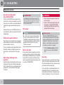
Important to know
General information about
Volvo C30 ELECTRIC
A Volvo C30 ELECTRIC has an electric drive
system but is driven and handled in much the
same way as a car with a conventional internal
combustion engine and automatic transmission.
However, there are some differences that are
not too obvious, which are explained in the following pages.
Safety with regard to batteries
The fuel tank of a conventional car is replaced
with batteries in this vehicle, which are fitted in
various locations in the car.
There is information about the batteries that is
important to know, and which concerns personal safety - read more about it on page
15.
High voltage and danger from
electricity
Under the bonnet and elsewhere in the car are
components that work with high voltage electricity. Carelessness may cause danger to personal safety - read more about it on pages
15 and 26.
4
WARNING
IMPORTANT
Pay attention to the fact that several 12V
fuses and relays have other functions and
values than their equivalents in a conventional fuel-driven C30.
•
Do not carry out any repairs of your own
on this vehicle.
•
Service, fault tracing, adjustments and/
or repairs on a Volvo C30 ELECTRIC
must only be performed by specifically
assigned Volvo workshops.
This manual
NOTE
Be careful not to remove this manual from
the car - should a problem arise then the
information required about where and how
to seek professional help would be missing,
amongst other things. See the section
"Service and repair".
IMPORTANT
This Volvo C30 ELECTRIC must only be
checked and/or repaired at the Volvo workshops specified when the car is collected/
handed over. Store these contact names,
addresses and telephone numbers safely.
In assistance or advice is required:
•
Service and repair
In the event of technical questions and/or the
need for assistance, contact the Volvo dealer
that handed over/delivered the car. Only workshops with the necessary specialised equipment and specially trained personnel may work
on a Volvo C30 ELECTRIC.
Call the telephone number obtained
when the car was collected/handed
over.
Recycling
Environmental care is one of Volvo Car Corporation's core values which guides all our activities. We also believe that our customers share
our concern for the environment.
As a part of Volvo's environmental work, it is
important that the car is recycled in an environmentally sound manner - this applies in particular to its batteries. The car's last owner is
01 C30 ELECTRIC
Important to know
therefore requested to contact a Volvo dealer
for referral to a certified/approved recycling
facility.
5
01 C30 ELECTRIC
Telematics - information about the drive system
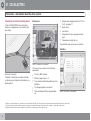
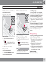
Information via Internet/mobile phone
Parameters
• Programmed charging current (6, 8, 10 or
16 A) - see page 17.
A Volvo C30 ELECTRIC stores information
about e.g. charging time, consumption, load
and similar.
• Alarm status.
• Lock status.
• Temperature in the passenger compartment.
• Temperature outside the car.
The specified values are shown in real time3.
Statistics
NOTE: The picture is schematic2.
The user can have access to the following
parameters:
Antenna for telematics.
Telematics information and certain statistics
on driving can be studied via the Internet or a
mobile phone1.
• The car's GPS position.
• Battery charge status in %.
• The current potential driving distance in the
batteries.
• The charging cable is connected.
• Time remaining until fully charged batter-
NOTE: The picture is schematic2.
ies.
1
2
3
6
Applies to certain mobile phones - telematics does not work with all models. A Volvo dealer can provide information about which mobile phones can be used.
As technology, functions and software are under continuous development the design of this Internet site is subject to change without prior notice.
Display in real time requires that the mobile phone is within the coverage range of the mobile network.
01 C30 ELECTRIC
Telematics - information about the drive system
Certain statistics for completed journeys are
also retrieved:
• When the car is used.
• When the batteries are charging.
• Distance in km for each trip.
• Energy consumption in kWh/100 km for
When the batteries are fully charged the live
transmission of system data is shut down. Following which, the telematics system only
sends updated data every 4 hours.
each trip.
• Average energy consumption in
kWh/100 km for each trip.
• Battery usage in % for each trip.
• Map track for each trip with start and end
points.
• Summary of the distance travelled and
energy consumption per week.
• Average distance travelled and energy
consumption per week.
The indicated statistical values are not current,
but appear with a certain delay - see "Limitations".
Access via Internet/mobile phone
Internet address, codes and user instructions
for telematics Internet connection are provided
to the user when the car is delivered/collected.
As printed instructions for using telematics on
the Internet become quickly obsolete and outof-date, they are omitted in this manual.
Instead, there is always an updated and current
version of the user instructions on the telematics Internet site. Study them carefully when first
connecting to the Internet.
An iPhone app can show the same information
as the Internet.
Limitations
To save energy, the car's control modules are
not permanently activated. This limits the
opportunity to send and log system data in real
time.
However, telematics information is always displayed in real time3 in the following cases:
3
Display in real time requires that the mobile phone is within the coverage range of the mobile network.
7
01 C30 ELECTRIC
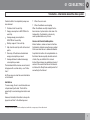
Combined instrument panel
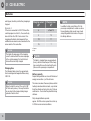
The following instruments differ from those in
a fuel-driven car:
- Speedometer
Shows the speed of the car.
WARNING
The maximum permitted speed with this car
is 130 km/h. If this speed is exceeded, on a
steep downhill slope for example, then the
driver must reduce speed with the foot
brake.
- Power meter
Shows the electric motor's power output or
recharging to the batteries.
• Left-hand scale (0-30) shows recharging to
the batteries.
• Right-hand scale (0-40) shows the electric
motor's power output.
- Energy consumption
Shows how much current is drawn from the
batteries to consumers other than the drive
motor.
The fewer the functions used the lower the
consumption, which means good electricity
economy.
It is less desirable for the needle to point far out
to the left, as the potential driving distance from
the batteries would then be shorter.
Large power consumers in this connection are
e.g. heated seats/mirrors, heated rear window
and the climate control system during extreme
cooling/heating.
- Battery capacity
Shows the remaining power supply in the batteries. It is equivalent to the "fuel gauge" in a
conventional car.
8
01 C30 ELECTRIC
Combined instrument panel
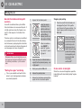
Symbols
- Reduced motor power
NOTE
The following symbols differ from those in a
fuel-driven car:
The READY lamp is not illuminated if the
charging cable is connected to the car.
- Charging cable
- Warning for low battery capacity
Reminds that the charging
cable is connected to the
electrical socket. The car cannot be driven when the charging cable is connected!
- Ready to drive
The green READY lamp
means that all systems are
ready - the car is thus ready
for use.
In parallel with the green lamp
illuminating, an acoustic signal ("ping") also verifies that the car is ready to
drive.
READY-The lamp illuminates
after the remote control key
has been turned to clockwise
end position and released (as
in normal engine starting) - the
lamp goes out after starting
driving.
Illuminates when the batteries
have sufficient energy for
approx. 10 km.
Remember that cold, high outside temperature, steep uphill gradients, heavy loads, sudden acceleration and sudden braking all
reduce the potential driving distance that can
be obtained from batteries.
NOTE
Illuminates when the batteries
start to become discharged or
when they cannot supply the
power the motor requests.
Can also be illuminated in
connection with driving on
steep uphill slopes or in very hot weather
(above 30 ºC).
The driver does not need to take any special
action - the car's electronics protect the motor
by temporarily making it slightly "weaker".
WARNING
Drive defensively when this symbol is illuminated - for example, it may not be possible temporarily to accelerate rapidly or overtake in a safe manner.
To avoid unplanned stopping after this symbol has illuminated:
•
Connect the car as soon as possible to
a grounded 230V AC socket in order to
recharge the batteries.
9
01 C30 ELECTRIC
Driving the car
General information on driving with
electricity
1.
A car with an electrical drive system differs
from a fuel-driven car in one essential point - it
is totally quiet even when the "engine is running". In other respects it is familiar to the
driver.
2.
The drive system is monitored and controlled
by a computer that assists the driver during
most instances by displaying text instructions
on the instrument panel's display. Examples of
such messages are shown on page 30.
3.
WARNING
Remember that an electrically-driven car is
silent and may therefore be difficult to notice
for children, pedestrians, cyclists and animals.
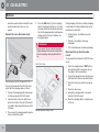
Insert the remote
control key in the
ignition switch and
turn clockwise to key
position III and
release (as with normal engine-starting).
When the indicator
lamp READY is
green the "engine
has started" - see no.
[4] page 9.
Stopping and parking
1.
Stop the car with the foot brake and
disengage the "gear" with a gentle
push forward on the gear selector - the
lamp for gear position changes from
D/H to N.
2.
Apply the parking
brake control gently,
and turn the remote
control key to anticlockwise end position 0 - the car is now
parked with parking
brake applied, parking lock activated
and "engine
switched off".
4.
Check that there is sufficient battery
capacity for the planned journey - see
no. [6] page 8.
5.
Select gear position D/H or R.
Cruise control - brake lights
• Put on your seatbelt and check that the
6.
Release the parking brake.
driver's seat, steering wheel and mirrors
are correctly adjusted.
7.
Release the foot brake and adjust the
speed with the "accelerator pedal".
When the cruise control regulates speed the
brake lights are lit automatically during "engine
braking".
"Starting the engine" and driving
10
Depress the foot brake pedal.
01 C30 ELECTRIC
Driving the car
Energy saving mode
To save battery capacity, the electrical system
goes down to low consumption after
approx. 10 minutes of inactivity, e.g. during
battery charging and after the car is locked.
With the remote control key in
the 0 position, the electrical
system is also set in energy
saving mode after
approx. 10 minutes of inactivity.
NOTE
When the electrical system changes over to
energy saving mode certain sounds may be
heard - this is due to strong relay contacts
changing position and is perfectly normal.
Situation
Waking
The car is locked.
Unlock the car.
The charging cable
is connected to 230
VAC.
Unplug the charging
cable from the car's
electrical input
socket.
The remote control
key is in the ignition
switch.
Turn the key to position I or II.
Gearbox
It then takes approx. 7 seconds for the car to
be ready to drive after having been "woken up"
from energy saving mode.
Gear selector and its positions.
To change gear:
• Press the spring-loaded gear selector forThe car can be woken up as follows:
ward or backward and then release it.
The gear selector has the following positions:
• R: Reverse position.
• N: Neutral (neutral position).
• D/H: Forward drive - Drive/Highway.
An illuminated lamp at each gear position on
the lever panel indicates the gear that is active.
11
01 C30 ELECTRIC
Driving the car
IMPORTANT
The car must be stationary with the foot
brake depressed when changing from N to
R or from N to D/H.
Gear D/H
The first backward movement of the lever activates forward drive with the gear in the D position. The second activates the H position. The
third activates the D position again, and so on.
• Parking lock On: Turn the remote control
Parking brake
key to position I1 or 0.
• Parking lock Off: Turn the remote control
key to position II1 and depress the foot
brake pedal.
WARNING
Make a habit of always applying the parking
brake when parking - the gearbox automatic
parking lock is not sufficient to hold the car
in all situations.
• D - Drive: For city driving. The "engine
braking" recharges the batteries.
• H - Highway: For driving on main roads.
Recharging with "engine braking" is
reduced.
When changing between D and H position the
instrument panel's gear shift indicator changes
between D and H.
Emergency disengagement of the
parking lock
In the event of a power failure the gearbox's
parking lock can be released manually - see
page 23.
Parking lock
In order that the car should not accidentally roll
away, it has the equivalent to the P position in
a conventional car's automatic gearbox. The
parking lock is operated automatically with the
remote control key as follows:
1
12
Key positions - see the normal owner's manual or the tables earlier on in this section.
Parking brake control button.
Function
The electric parking brake acts on the rear
wheels and when it is working a faint sound
may be perceptible. The noise can also be
heard during the automatic function checking
of the parking brake.
Emergency brake
In an emergency the parking brake can be
"pulled" even if the car is moving, but the braking then takes place with reduced power until
the car is stationary - only then is the parking
brake fully applied.
01 C30 ELECTRIC
Driving the car
If the brake control is released then the emergency braking is interrupted.
• Turn the wheels towards the kerb.
Releasing the parking brake
Applying the parking brake
Low battery voltage
If the battery voltage is too low, the parking
brake cannot be released or applied. In order
to operate the parking brake, an external battery must be connected - see the normal
owner's manual, section "Starting and driving
> Start assistance > Starting with a donor battery" for how it works.
Emergency disengagement of the brake
In the event that the parking brake cannot be
released (e.g. if the car becomes de-energised
and an external battery is not available) it can
be released manually/mechanically - see
page 23.
Thinking electrically
Release: Press the button.
Apply: Pull the button.
1. Pull the control slightly up once and
release.
>
The brake is applied when the
combined instrument panel's symbol
illuminates.
1. Depress the foot brake pedal firmly.
2. Press the control slightly down once and
release.
>
The combined instrument panel's symbol goes out - the parking brake
is released.
2. Make sure the car is stationary.
Parking on a hill
If the car is parked facing uphill:
• Turn the wheels away from the kerb.
NOTE
The foot brake must be depressed before
the parking brake can be released.
Driving a car with batteries as the power source
involves a different way of thinking:
• Knowing where battery charging is possible will become an important detail in
everyday life.
• Make sure that the batteries are fully
charged prior to a longer journey.
• Prioritise choosing a parking space with a
230 V AC grounded socket - then the car
can constantly have a "full tank".
Driving techniques
Bear in mind the following:
If the car is parked facing downhill:
13
01 C30 ELECTRIC
Driving the car
• Never drive through deep pools of water -
• Use "engine braking" when braking - it
water must not reach higher than the lower
edge of the rim.
• "Engine braking" is more noticeable in D
recharges the batteries and extends the
potential driving distance.
considerably due to increased wind resistance - doubling speed increases wind
resistance 4 times.
NOTE
Daytime running lights - DRL
With the light switch in position A (Automatic)
the DRL lights (Day Running Light) in the spoiler
are automatically activated during daytime.
This is regulated by a light sensor which
switches from DRL daytime running lights to
the headlamps' dipped beam at twilight or
when daylight is too weak.
• A disengaged AC results in an additional
DRL lamps use energy-saving LED technology
which extends the potential driving distance.
few kilometres driving distance.
NOTE
• Drive with the recommended air pressure
in the tyres.
• Empty the car of unnecessary items - load
with a high weight reduces possible driving
distance.
• Drive smoothly and avoid sudden braking.
14
The remote control
key must be in key
position II.
recommended service intervals.
Here is some advice that reduces power consumption (= longer potential driving distance)
without the need for travelling time to increase
or driving pleasure to decrease.
wind resistance, which increases power
consumption - remove them immediately
after use.
1.
• Maintain the car regularly - follow Volvo's
Driving tips
• Space box and load carriers result in higher
Consider the following if the car needs to be
moved/manoeuvred by hand or towed:
• High speed increases power consumption
position than in a conventional car.
Make a habit of always starting a journey
with fully-charged batteries.
Towing
To achieve minimal energy consumption,
the rear lights are also switched off when the
lighting automatically switches from dipped
beam to DRL lights.
•
There is further important information
on the DRL lights in the normal owner's
manual for the car - Read it!
2.
Set the gear lever in N position.
3.
Release the parking brake.
See also the information on towing in the normal owner's manual.
WARNING
The brakes and power steering do not work
if the car is de-energised. Approximately 5
times harder pressure on the brake pedal is
required and the steering is considerably
heavier than normal.
IMPORTANT
Avoid using a Volvo C30 ELECTRIC to tow/
recover another vehicle.
01 C30 ELECTRIC
Batteries
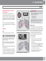
Charging the batteries
Safety
In extreme situations there is the
possibility that the batteries may
become overheated.
If this occurs, a warning signal will be heard and
a red warning symbol will be illuminated on the
instrument panel, combined with an explanatory display text.
Stop the car immediately in a safe manner and
leave it as soon as possible. Then contact the
hirer or a workshop1.
WARNING
Stop and immediately leave the car if the
alarm signal sounds and the red warning
symbol illuminates together with the display
text STOP SAFELY - LEAVE THE
VEHICLE.
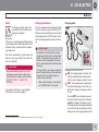
Charging cable
The car is equipped with rechargeable batteries of the Lithium-ion type (Lithium-ion). The
batteries are fully maintenance-free but must
be recharged from a 230 V AC mains circuit
with the charging cable that comes with the
car.
IMPORTANT
Pay attention to the fact that the car also
consumes electricity when it is locked and
parked. The monitoring system checks, for
example, that the temperature of the batteries is optimal and heats/cools them when
necessary.
To ensure that the car is always ready to be
driven it should therefore not be parked for
longer than 24 hours without being connected to mains electricity.
•
Make a habit of always connecting the
car to 230V AC when it is parked.
For workshop staff there is special battery
information to consider on page 28.
Charging cable with control unit.
ON: The charging cable is activated - the
indicator lamp illuminates which verifies
that the mains voltage is routed to the car.
TEST: The charging cable is deactivated the indicator lamp goes out and this verifies that the voltage is no longer routed to
the car.
Pressing TEST once simulates a ground
fault and the built-in ground fault breaker
should then trigger and thereby prevent
the charging cable routing mains voltage to
the car. Should that not take place: Immediately remove the charging cable from the
1
Note that only specific Volvo workshops may carry out work on this car, see page 4.
15
01 C30 ELECTRIC
Batteries
electrical socket and then contact the designated workshop for the car - see
page 4.
Connect the car to the mains circuit
4. Press the ON button (1) on the charging
cable's integrated control box - its indicator lamp should then illuminate which verifies that the charging cable is routing mains
voltage and that the car's batteries are
being recharged.
During charging, the status of battery charging
is indicated with a blue indicator lamp on the
windscreen's alarm LED.
• Constant glow - the batteries are fully
charged.
• Flashing - the batteries are being
recharged.
WARNING
Do not connect the car's electrical system
to high voltage with an electrical cable other
than the charging cable supplied with the
car.
Indicator lamp
• Off - the batteries are not receiving charge.
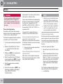
Disconnect the car from the mains
circuit.
To disconnect the car from the 230 V AC mains
circuit:
1. Press the charging cable's TEST button, the control module's lamp goes out and
the cable is then de-energised.
2. Push in the release button on the plug and
pull it right out of the car's electrical socket.
Electrical socket for 230 VAC and 6/8/10/16 A.
3. Close the inner cover over the connector
pins.
The car is connected to the 230 V AC mains
circuit with the charging cable as follows:
2. Open the hatch in the car's grille, then
press the button on the side of the electrical socket's internal protective cap so that
it folds up.
6. Store the charging cable in suitable place
in the car.
G020227
5. Unplug the charging cable's connector
from the 230 V AC socket.
3. Then connect the charging cable's plug to
the car's electrical socket.
16
4. Close the outer cover.
1. Connect the charging cable's wall connector into a grounded 230 V AC socket.
Indicator lamp for charge status.
01 C30 ELECTRIC
Batteries
Control unit
The charging cable's control unit
has an integrated ground fault
breaker. Adjacent to the unit's ON
button (1) is an indicator lamp - it
can have the following meanings:
Lamp
Off
Information
On
The charging cable is routing
electricity and the car's batteries are being recharged.
Off
The ground fault breaker has
triggered - there may be a fault
in the charging cable or in the
car's electrical system.
Off
Lamp
The 230 V AC mains circuit's
fuse may have been tripped check the mains fuse.
Off
Information
The 230 V AC mains circuit's
fuse may have been tripped check that the mains fuse value
is programmed into the car's
electrical system (see next section "Charging current").
The electric socket has no
ground connection - connect
the charging cable into a
grounded electrical socket.
WARNING
In the event of malfunctioning or the slightest doubt about a function - contact the
Volvo workshop that was specified when
the car was delivered (see page 4).
•
Never carry out fault diagnosis or
repairs yourself.
Charging current
Before the car's electrical system is connected
to a grounded 230 V AC mains circuit it is
important that the car receives correct information about the current intensity that the
230 V system has. The setting is made with the
left-hand stalk switch thumbwheel:
• Select 6, 8, 10 or 16 A from the menu. (For
more information, see page 30.)
IMPORTANT
Ensure that the correct fuse value
(6/8/10/16 A) is specified for the car's battery charging.
Tip
Not all 230 V sockets state their level of fuse
protection. If the socket's capacity is unknown,
choose one of the lower alternatives - 6 A or
8 A - to avoid the risk that the mains fuse is
tripped after a short time. It is better that the
batteries receive low and slow charging than
no charging at all.
The following example explains the logic:
Example 1
If the car is connected to 230 V/10 A and the
control program is set at 16 A, the car will
attempt to draw 16 A from the 230 V mains circuit - after a while the overloaded 10 A fuse will
be tripped and battery charging stopped.
Example 2
If the car is connected to 230 V/10 A but the
control program is set at 10 A, the car will draw
10 A from the mains circuit - if further consumers are connected to the same socket then
there is a risk that the fuse will be overloaded
17
01 C30 ELECTRIC
Batteries
and tripped, at which point battery charging is
stopped.
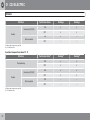
Charging current
(A)A
Charging time
(h)B
6
at least 19
8
15
10
11
16
7
Example 3
If the car is connected to 230 V/10 A and the
control program is set at 6 A, the car will only
draw 6 A from the 230 V mains circuit - the
charging will certainly take longer but then
additional consumers can be connected to the
same socket at the same time.
NOTE
The higher the amperage of the charging
current combined with the same amperage
in the control program, the faster the batteries will become fully charged.
Charging time
The following table shows the approximate
time to recharge discharged batteries using
230 V AC.
NOTE
Make it a habit to connect the car to 230V
AC after each journey - this way the batteries are also trickle-charged during longer
periods of inactive time.
A
B
Ampere
hour
NOTE
The table's charging times are approximate.
In very cold or hot weather part of the charging current will be used to heat/cool the batteries and the passenger compartment.
Battery capacity
People driving electric cars have to think about
energy conservation - just like at home.
The more consumers there are (stereo, electric
heating in windows/mirrors/seats, very cold air
from the climate control system, etc.) that are
switched on - the shorter the potential driving
distance.
Fully charged batteries provide
approx. 24 kWh and can power the car for up
to 150 km under normal conditions.
18
NOTE
In addition to high current take-off in the
passenger compartment, sudden acceleration and braking, high speed, heavy loads
and uphill gradients also reduce the possible driving distance.
01 C30 ELECTRIC
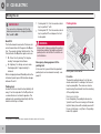
Climate
General information on the climate
control system
IMPORTANT
The car is supplied with one of the following
fuel-driven heating systems:
The climate control system works with a
hydronic heating system which is powered by
electricity or fuel and is operated using the climate control panel's controls. Cooling (AC) is
generated by an electrically-driven compressor.
•
•
95 octane petrol
These two fuels must never be mixed up or
mixed together with each other - so check
that the correct fuel is filled in the tank.
The car's computer system checks battery
temperature and maintains it within the desired
range.
Battery or fuel
Operation
Cars with fuel system for ethanol E85.
Fuel
The heater consumes approx. 1 litre/hour.
NOTE
The climate control system is powered either
by the batteries or fuel - the driver can choose
which should be prioritised. For longer driving
distances the recommendation is to run the
passenger compartment heater with fuel
because electrically generated heat reduces
the driving distance.
Proceed as follows:
The fuel tank must contain at least 1 litre for
the heater to start - a display text warns if
the level is too low.
1. Scroll to the menu bar FUEL HEATER
AUTO with the left-hand stalk switch
thumbwheel.
The heater generates condensation water
which runs down to the ground under the
car.
2. Select and activate ON or OFF with a long
press on the stalk switch RESET button.
• The option FUEL HEATER AUTO ON pro-
Filling with fuel
The fuel-driven heating system is available in
two variants - the difference is in the fuel which
is specified on the inside of the fuel filler flap in
accordance with the following illustrations:
Bioethanol E85
vides fuel-driven heat source.
• The option FUEL HEATER AUTO OFF
provides electrical heat source.
Cars with fuel system for 95 octane petrol.
19
01 C30 ELECTRIC
Climate
WARNING
The heater generates unhealthy emissions
during operation with fuel. Program the
timer for electric operation when the car is
used - or parked - in an enclosed/unventilated area.
Timer-set heating/cooling
The climate control system can be pre-programmed to heat the passenger compartment
- within 24 hours - before setting off.
The time that is programmed refers to when the
car shall be used. Proceed as follows:
1. Turn the remote control key to key position
I.
2. Select the PRECONDITIONI. TIMER 1
--:-- menu with left-hand stalk switch
thumbwheel.
3. Briefly press RESET - the character position for hour starts flashing.
4. Select the required hour with the thumbwheel and briefly press RESET - the character position for minutes starts flashing.
5. Select the required minute and briefly
press RESET.
6. Finish with a long press on RESET - programming is complete and the display
shows TIMER ACTIVE FOR
PRECONDITIONI..
20
Following which, the climate system automatically selects a suitable start time.
There is more information about programming
the time on the normal owner's manual. Note
then that what is designated in the C30
ELECTRIC as PRECONDITIONI. TIMER 1 is
the equivalent of PARK HEAT TIMER 1 in a
conventional C30.
On page 30 in this supplement there are
examples of more climate-related menus.
NOTE
•
When the car is not connected to mains
electricity the "Timer-set heating" can
only be activated if the FUEL HEATER
AUTO - ON menu option is selected.
•
Cooling of the passenger compartment
via AC is not possible when the car is
not connected to mains electricity.
Continuous heating/cooling
When the car is connected to mains electricity,
the batteries will always be used as the energy
source for the heating.
If the driver wants the car warmed up or cooled
down in advance, but does not know what time
the car will be used, then the climate control
system can be programmed to heat/cool continuously.
• If necessary, the passenger compartment
In which case, proceed as follows:
Timer-set heating/cooling with the car
connected to mains electricity
is cooled with the AC.
Timer-set heating without connection to
mains electricity
When the car is not connected to mains electricity fuel is used as the heat source. In which
case, please note the following:
1. Connect the car to the 230 V AC mains circuit.
2. Follow the preceding instructions for programming and select the time 00:00 for
TIMER 1 or TIMER 2 - the climate control
system will then keep the car constantly
"ready to start" with heated/cooled passenger compartment and fully charged
batteries.
The "Continuous heating/cooling" function is
active until the time 00:00 is replaced with
--:-- or another time.
01 C30 ELECTRIC
Climate
Heating and/or cooling
NOTE
Continuous heating/cooling is only possible
when the car is connected to mains electricity.
The following tables show in which situations it
is possible to generate heating or cooling and
which settings need to be made.
In outdoor temperatures below 3 °C
Situation
Fuel heater AutoA
HeatingB
CoolingB
ON
Ⴋ
–
OFF
Ⴋ
–
ON
Ⴋ
–
OFF
Ⴋ
–
ON
Ⴋ
–
OFF
–
–
Fuel heater AutoA
HeatingB
CoolingB
ON
Ⴋ
Ⴋ
OFF
Ⴋ
Ⴋ
During driving
Connected 230 VAC
Parked
Not connected
A
B
Setting in trip computer,see page 30.
Ⴋ = Possible function.
In outdoor temperatures between 3 and 15 °C
Situation
During driving
21
01 C30 ELECTRIC
Climate
Situation
Fuel heater AutoA
HeatingB
CoolingB
ON
Ⴋ
Ⴋ
OFF
Ⴋ
Ⴋ
ON
Ⴋ
–
OFF
–
–
Fuel heater AutoA
HeatingB
CoolingB
ON
Ⴋ
Ⴋ
OFF
Ⴋ
Ⴋ
ON
Ⴋ
Ⴋ
OFF
Ⴋ
Ⴋ
ON
–
–
OFF
–
–
Connected 230 VAC
Parked
Not connected
A
B
Setting in trip computer,see page 30.
Ⴋ = Possible function.
In outdoor temperatures above 15 °C
Situation
During driving
Connected 230 VAC
Parked
Not connected
A
B
22
Setting in trip computer,see page 30.
Ⴋ = Possible function.
01 C30 ELECTRIC
Maintenance and service
Parking brake - emergency
disengagement
In the event that the parking brake cannot be
released (e.g. if the car becomes de-energised)
it can be released manually/mechanically to
make it possible to move the car - proceed as
follows:
4. Grasp the handle and gently pull up, pull
until a "click" can be sensed - by these
means the parking brake is released and
the car can be moved.
WARNING
Chock the wheels before the parking brake
is disengaged manually - otherwise the car
could start to move uncontrollably.
•
Use chocks for the rear wheels.
Parking lock - manual release
In the event of power failure with the gear
selector in P position, the car cannot be
moved. If the car then needs be rolled away or
recovered, the gearbox's mechanical inhibitor
can be disengaged manually. This requires a
so-called "Recovery cable" which comes with
the car and is stored in the cargo area.
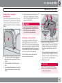
1. First, make sure that the rear wheels are
blocked in some way, e.g. with chocks or
similar.
First, the electric motor's cover must be
removed - proceed as follows:
The motor cover's attachment points.
1. Grasp the edge of the cover at (A) and (B)
and pull it straight up a few centimetres the cover is released from its two front
studs.
2. Grasp underneath the edge of the cover at
(C) and (D) and pull it straight up a few centimetres - the cover is released from its two
rear studs and is now fully released.
3. Set the cover aside.
2. Fold the backrest on the left-hand rear
seat.
3. Look between the backrest and under the
cargo area floor and pull out the line with
handle.
WARNING
There is little space around the electric
motor's cover, and there are sharp edges.
•
Use protective gloves.
23
01 C30 ELECTRIC
Maintenance and service
Following this the Recovery cable is connected
- proceed as follows:
3. Locate the Recovery cable's connection
point (A).
4. Press and release the catch for the connectors and pull out the right-hand half to
the right (seen from the driver's seat).
Connection point for the Recovery cable.
IMPORTANT
Hold the connectors when disattaching - do
not hold and pull the electrical cables.
1. First, make sure that the rear wheels are
blocked in some way, e.g. with chocks or
similar.
2. The check that the parking brake is
released. See separate instructions in the
section "Parking brake - emergency disengagement".
24
If this process does not work - contact a workshop, see page 4 for information on a suitable
workshop.
WARNING
5. Connect the Recovery cable's connector
in the loosened "right-hand connector
half" - press the connector halves together
until they lock with a "click".
Chock the wheels before the parking lock is
disengaged manually with the Recovery
cable - otherwise the car could start to move
uncontrollably.
6. Connect the Recovery cable's black
clamp to the negative terminal on a
12 V DC battery.
•
7. Then hold the Recovery cable's red clamp
to the positive terminal of the
12 V DC battery for a few seconds - a
sound can be perceived from the electric
motor as it disengages the inhibitor.
8. Check that the car can be rolled a few decimetres forward/backward in order to verify
that the inhibitor has released.
9. Remove the Recovery cable from the battery.
10. NOTE: Do not reconnect the car's connectors to the now "empty" connector half
(A) again - leave it for the Volvo workshop
where the car is recovered to.
11. Align the cover's 4 rubber caps over each
stud and push the cover into place.
12. Refit the Recovery cable in the cargo area.
Use chocks for the rear wheels.
Washing the car
As the car is equipped with components
designed for connection to 230 V AC high-voltage, it is very important that these parts are not
exposed to moisture, fluids and/or aggressive
chemicals and/or solvents.
IMPORTANT
Do not wash the space under the bonnet
with a high-pressure unit.
automatic car wash
In an automatic car wash - where the car is
towed through the cleaning system - the
wheels must be able to roll freely. In which
case, proceed as follows:
01 C30 ELECTRIC
Maintenance and service
1. Drive into the washing facility and hold the
car with the foot brake.
2. With gear position D still activated: Turn
the remote control key to key position 0 see page 11.
3. Then turn the remote control key back to
position II and take your foot off the foot
brake - the car can now roll freely.
After washing is finished:
1. Depress the foot brake.
2. Activate D position with the gear selector
and drive out of the washing facility.
Wheels & tyres
Dimension
When fitting new tyres, the same type and
make as originally fitted in the factory are recommended. If the event of uncertainty - consult
the workshop that was specified when the car
was collected/handed over - see page 4.
Approved dimensions:
Payload
For information on the permitted maximum
weights - see the decal on the right-hand door
pillar and the registration document.
roof load
Fitting load carriers on the roof is not recommended - the increased wind resistance
reduces the potential driving distance drastically.
Trailers
It is not possible to fit a towbar.
Under the bonnet
One of the car's batteries and several of the
components included in the car's electric drive
system are located under the bonnet. Exercise
caution in this area and only touch anything
that is related to normal maintenance.
• 205/55R16
Tyre pressure
•
• 250 kPa.
Checking/refilling washer fluid.
Checking/refilling brake fluid.
Fuses (see page 26).
Checking/filling power steering fluid.
NOTE
In the event of uncertainty over which selfservice operations may/can be carried out
by the driver:
Recommended pressure in all tyres:
Normal checking points - other parts require specialist expertise.
Ask for advice from the workshop that
was specified when the car was collected/handed over - see page 4.
•
Checking/refilling water for the cooling and
climate control systems.
Avoid spills - clean up thoroughly if they do
occur.
25
01 C30 ELECTRIC
Maintenance and service
WARNING
Several components in the car operate with
lethal high-voltage electricity.
•
Do not touch anything under the bonnet
that is not clearly described in the
owner's manual or in this supplement.
•
Exercise caution when checking/refilling fluids under the bonnet.
reason, it is absolutely forbidden, for example,
to:
• open boxes/control modules
• remove panels under the car
• work with/change the car's electrical sys-
Fuses
Several of the fuses described in the normal
owner's manual are missing in a
Volvo C30 ELECTRIC or protect other functions.
tem
• work with orange cables (400 V system)
• replace brake pipes that are routed into the
"engine compartment".
Self service
Some repair work on the car can be carried out
independently by the car owner provided that
he/she possesses the necessary knowledge.
For example:
•
•
•
•
•
WARNING
changing wheels
replacing light bulbs
replacing the 12 V DC battery
replacing windscreen wiper blades
changing 12 V fuses in the "engine compartment" and passenger compartment
• replacing wear parts in the brake system
(e.g. discs and linings).
See the normal owner's manual for more information on these points.
Danger electricity
Be aware that parts of the car's electrical system work with 400 V DC high voltage! For this
26
This and similar work must only be carried out
by special workshops with specially trained
personnel - see page 4.
Sections of the car containing
high voltage are marked with the adjacent
symbol.
Pay attention to the fact that the orange
cables carry lethal high voltage.
Fuse and relay box under the bonnet.
Fuses with bold no. have another function related to them in a fuel-driven car:
N
o.
Component
A
1
Cooling fan
50
2
Power steering
80
01 C30 ELECTRIC
Maintenance and service
N
o.
Component
A
N
o.
Component
A
N
o.
Component
3
Supply to fuse box in the passenger compartment
60
18
Supply to fuse box in the passenger compartment
40
30
7.5
4
Supply to fuse box in the passenger compartment
60
19
–
Electric Vehicle Module (EVM)E
and Engine Control Module
(ECM)F
20
horn
15
31
10
5
PTC element, air preheater
80
Emergency disconnection, batteries 400 V
21
Electric parking brake
30
Fuel-driven additional heater/
passenger compartment heater
20
6
32
Engine Control Module (ECM)F
5
7
ABS pump
40
22
7.5
33
gear selector
5
8
ABS valves
20
Central Software Module
(CSM)A
34
–
–
23
Control module, electric vehicle
R7+R11
5
35
–
–
36
Accelerator pedal sensor
24
Control unit, batteries
10
9
Motor functions
30
10
ventilation fan
40
–
11
headlamp washer
20
25
Water pumps
20
12
heated rear window
30
26
ignition switch
15
13
Vacuum pump, brakes
40
27
Battery climate unit
40
Advanced Information Control
Module (AICM)C
7.5
14
15
Central Software Module
(CSM)A with slave (SCSM)B
30
28
–
16
Infotainment
30
17
windscreen wiper
30
29
Daytime Running Light
A
B
C
D
E
F
A
10
CSM: Central Software Module
SCSM: Slave to Central Software Module
AICM: Advanced Information Control Module
DRL: Daytime Running Light
EVM: Electric Vehicle Module
ECM: Engine Control Module
–
(DRL)D
15
27
01 C30 ELECTRIC
Maintenance and service
Relays
No.
Component
Relays with bold no. have another function
related to them in a fuel-driven car:
R13
Vacuum pump, brakes
R14
Motor functions
No.
Component
R1
–
R2
horn
R3
–
Workshop information about batteries
R4
DRL lights
Oven drying after painting
R5
Emergency disconnection, batteries 400 V
R6
Batteries 400 V
R7
Central Software Module (CSM)A
with slave (SCSM)B
R8
–
R9
headlamp washer
R10
heated rear window
R11
Advanced Information Control
Module (AICM)C
A
B
C
CSM: Central Software Module
SCSM: Slave to Central Software Module
AICM: Advanced Information Control Module
In the event that the car shall be painted, it is
important that the batteries are not exposed to
temperatures higher than 80 °C, so great care
must be taken with oven drying.
In which case, also bear in mind that at a battery temperature above 45 °C the car's climate
control system will attempt to lower the temperature - so the following applies:
IMPORTANT
The car must be connected to 230V AC with
the original charging cable during the whole
the time in a drying facility.
Infra-red heat
R12
28
–
A Volvo C30 ELECTRIC can placed in a drying
facility with infra-red heat for a maximum of
2 hours, provided that the temperature does
not exceed 70 °C.
"Hot room"
A Volvo C30 ELECTRIC must not be placed in
a drying facility of the "hot room" type because
they dry car paint over a longer time.
Weights and specifications
Passenger compartment heater
Fuel tank (volume)
approx.
14.5 litres
Consumption, (per hour)
approx. 1.0
litres
Consumption, electricity (per
hour)
approx. 5.0
kWh
Electric drive motor
Continuous output
40 kW/54 hp
Maximum output
82 kW/110 hp
Maximum power output
approx. 30 seconds
Torque
223 Nm
Hill climbing capacity
>20 %
01 C30 ELECTRIC
Maintenance and service
Batteries for drive motor
A
Type
Lithium-ionA
Continuous voltage
280-400 V DC
Power supply
approx. 24 kWh
Service life
approx. 3000
cycles
Charging time for discharged batteries
see table page 18
Lithium-ion
NOTE
At outside temperatures below -10 ºC or
above 30 ºC the car's functions cannot be
fully guaranteed, as the capacity of the batteries is reduced outside of this temperature
range.
29
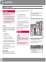
01 C30 ELECTRIC
Display messages and menus
Text information in the display
Different messages and information can be
seen in the combined instrument panel's display - sometimes together with some of the
or
.
symbols on page 9 or with these:
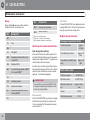
trip computer
One of the following menus can be selected for
permanent display in the trip computer:
Menus/settings
Information in the display
PRECONDITIONI. TIMER 1 --:-- ON/OFFA
AC SERV. REQUIRED
PRECONDITIONI. TIMER 2 --:-- ON/OFFB
BCUA SER. REQUIRED
CHARGING CURRENT 6A
BATTERY FAILURE - REDUCED FUNCTION
CHARGING CURRENT 8A
BATTERY FAILURE - SERVICE REQUIRED
CHARGING CURRENT 10A
BATTERY FAILURE - SERVICE URGENT
trip computer
--.- KWh/100 KM - INSTANTANEOUS
--.- KWh/100 KM - AVERAGE
--.- KILOMETRES - RANGE
• Select menu with left-hand stalk switch
thumbwheel.
CHARGING CURRENT 16A
A
B
VEHICLE FAILURE - REDUCED FUNCTION
Preconditioning: timer-set heating/cooling of the passenger
compartment.
Alternatively, the time for the timer-set heating of the passenger compartment.
VEHICLE FAILURE - SERVICE REQUIRED
HIGH MOTOR TEMP - SERVICE URGENT
• Use the left-hand stalk switch thumbwheel
MOTOR - REDUCED FUNCTION
to select the required menu - a short press
on the stalk switch RESET button gives
OFF position, a long press gives ON position.
MOTOR FAILURE - SERVICE REQUIRED
PARKING BRAKE - REDUCED FUNCTION
Settings
The following adjustments/settings can be
made:
Menus/settings
--.- LITRES LEFT - FUEL HEATER
DIRECT START FUEL HEAT. - ON/OFF
FUEL HEATER AUTO - ON/OFF
30
Information with action
Several messages are shown when something
in the car does not have full functionality. These
messages require that a workshop be contacted - see page 4 for information on a suitable
workshop. Examples of such messages are:
PARKING BRAKE - SERVICE REQUIRED
P-LOCK FAILURE - SERVICE URGENT
STOP SAFELY - LEAVE THE VEHICLE
A
BCU: Battery Climate Unit.
• A text message can be acknowledged by
briefly pressing the READ button on the
left-hand stalk switch.
01 C30 ELECTRIC
Display messages and menus
Information without action
Many messages are a prompt to help the
driver, or to show the status of a particular
function. Here are some examples:
Information in the display
BRAKE TO RELEASE P-LOCK
BRAKE TO CHANGE GEAR
Information in the display
TIMER IS SET FOR PRECONDITIONI.
TURN KEY TO START
HEATER STOPPED - LOW FUEL LEVEL
• A text message can be acknowledged by
briefly pressing the READ button on the
left-hand stalk switch.
BRAKE VACUUM LOW
FUEL HEATER - LOW LEVEL
FUEL HEATER - EMPTY
CHARGING CABLE CONNECTED
LOW BATTERY
LOW BATTERY VOLTAGE
PARKING BRAKE ACTIVATED
PARKING BRAKE - MISUSE
STARTING UP
REDUCE SPEED
REDUCE SPEED TO CHANGE GEAR
FUEL FILLER CAP OPEN/LOOSE
31
01 C30 ELECTRIC
32
Kdakd8Vg8dgedgVi^dc51&OHMJTI
"51SJOUFEJO4XFEFO(zUFCPSH$PQZSJHIU©7PMWP$BS$PSQPSBUJPO