1
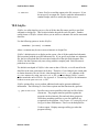
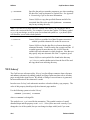
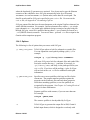
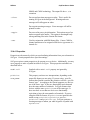
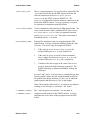
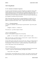
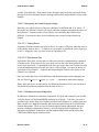
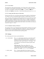
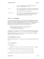
12 Utilities ..................................................................................................................................................12-1
12.1 Partlist............................................................................................................................................12-1
12.2 Schfiles ...........................................................................................................................................12-3
12.3 Schxref............................................................................................................................................12-4
12.4 Sch2gem .........................................................................................................................................12-5
12.4.1 Overview .................................................................................................................................12-6
12.4.2 Getting Started.........................................................................................................................12-6
12.4.2.1 Invoking Sch2gem............................................................................................................12-6
12.4.3 Options ....................................................................................................................................12-7
12.4.4 Properties.................................................................................................................................12-8
12.4.5 Using Gemini.........................................................................................................................12-10
12.4.5.1 Schematic-to-Schematic Comparison .............................................................................12-10
12.4.5.1.1 Generating Netlists ..................................................................................................12-10
12.4.5.1.2 Running Gemini.......................................................................................................12-10
12.4.5.1.3 Dictionary file..........................................................................................................12-10
12.4.5.2 Interpreting the Gemini Program Output ........................................................................12-11
12.4.5.2.1 Finding Errors..........................................................................................................12-11
12.4.5.2.2 Equivalence files......................................................................................................12-11
12.4.5.3 Schematic-to-Layout Comparison ..................................................................................12-11
12.4.5.3.1 Invoking Sch2gem for SIM file format....................................................................12-12
12.4.5.3.2 Invoking Gemini......................................................................................................12-12
12.5 Partsmnu ......................................................................................................................................12-13
12.5.1 Invoking Partsmnu ................................................................................................................12-13
12.5.2 Menu Hierarchy.....................................................................................................................12-13
12.5.2.1 Parent Menu ...................................................................................................................12-14
12.5.2.2 Creating More Than One New Parts Menu ....................................................................12-14
12.5.2.3 Maximum Number of Characters ...................................................................................12-14
12.5.3 Options ..................................................................................................................................12-14
12.5.4 cad.rc File Changes ...............................................................................................................12-15
12.5.5 Sample Run of Partsmnu.......................................................................................................12-15
12.5.5.1 Command Line ...............................................................................................................12-15
12.5.5.2 cad.rc File Additions ......................................................................................................12-16
12.5.6 Partsmnu Error Messages......................................................................................................12-17
12.5.6.1 Warnings ........................................................................................................................12-17
12.5.6.2 Fatal Errors.....................................................................................................................12-17
Chapter
12 Utilities
This chapter shows you how to use the CapFast utility programs. These programs cover a
wide range of functions. Here’s a list of the programs and what they’ll do.
•
Bill-of-Materials Generator (Partlist) — generates a bill of materials your
design.
•
Design Archiving Utility (Schfiles) — creates a list of all the data files that you
have used in a schematic or design file
•
Design Cross-Reference Generator (Schxref) — creates a list of offpage
connector sheet references and annotates schematics by adding symbols at
offpage connectors.
•
CapFast Gemini Netlister (Sch2gem) — creates a netlister from your schematic
that you can use as input to Gemini for verification.
•
Part Menu Generator (Partsmnu) — lets you create additional parts menus for
Schedit.
12.1 Partlist
Partlist generates a bill of materials from your design (.dsn) or schematic (.sch) file.
You may invoke Partlist in UNIX by typing the following command at the operating
system prompt:
partlist [-f FLAGS][-o OUTFILE] FILENAME
If Partlist does not find the pqty property on a symbol, it will assume a value of 1.
Additionally, if there is no ref property present on each symbol, Partlist may give
erroneous output.
Any of the following flags can be used with the -f option to generate specific
information about the parts in a schematic:
d
Device name. Uses concatenation of prefix, primitive, and suffix
property values, or device property. Field width is 19.
p
Uses partcode property. Field width is 19.
Release 3.02.23
12-1
Utilities
CapFast User’s Guide
q
Quantity of physical packages, including connectors. A rough quantity
estimate is given for symbols with no reference designators. Field width is 6.
g
Number of logical parts, including connectors. Field width is 6.
f
Number of unused (free) logical parts, including connectors, in the physical
packages that Partlist has determined are in the design. Field width is 6.
u
Number of logical parts, including connectors, without a reference property.
Field width is 6.
r
Reference designator. Uses value of ref property. Field width is 32.
c
Part description. Uses value of comment property. Field width is 32.
By default, Partlist lists the following information:
Device name
Partcode
Quantity of physical packages, including connectors
Part description
This listing produces 80-column output. Notice that the default listing is equivalent to
using the -f option with the flags dpqc. If you use all flags, Partlist produces 132column output. In either case, the output is sorted by complete line contents.
Partlist provides 60 lines per page of output, including header and footer margins. Each
page contains a column header, and the first page provides totals for each number field
printed. Form feeds are provided only when Partlist prints to a file.
The following other options are available:
-Q QUALIFIER-LIST
Specifies one or more qualifiers which are in effect for the
current run. The program matches qualifiers against the
properties in the schematic files and only those properties
which have matching qualifiers, or are not qualified, are
recognized by the program. See Chapter 4: Creating Electrical
Designs for more information. There is no default qualifier.
-v
Verbose output. Displays messages telling you what the
program is doing.
-p PATHNAME
Specifies the path you want the program to use when searching
for data files, such as schematic or symbol files. See Appendix
A: Customizing CapFast for more information.
12-2
Release 3.02.23
CapFast User’s Guide
-o OUTFILE
Utilities
Causes Partlist to send the output to the file OUTFILE. If you
do not specify an output file, Partlist sends the information to
standard output, which is usually the display screen.
12.2 Schfiles
Schfiles is a utility that lets you see a list of all the data file names used by a specified
schematic or design file. This list also includes the path for each file name. Another
useful feature of Schfiles is that it allows you to archive a schematic file and its associated
data files.
Use the following syntax to invoke Schfiles:
schfiles [OPTIONS] FILENAME
where FILENAME may be one or more schematic or design files.
Schfiles’s default action is to display on the screen a list of all the symbol and schematic
files associated with the specified schematic file. If you specify more than one schematic
file, the list will include the files associated with each of the specified schematic files.
Schfiles lists the file name only once, along with the complete path. Each file name is
printed on its own line.
The default search path of Schfiles is the same as that of Schedit, so it will search for the
data files in the same order that Schedit does. Therefore, if you changed your search path
to obtain alternative files in Schedit, either through the Search Path submenu of the
Options menu or by using your own cad.rc file, you must change Schfiles’s search
path to match the one in Schedit. See Appendix A: Customizing CapFast for information
on how to create your own cad.rc file.
Schfiles options allow you to perform additional tasks and to generate additional
information. The following is a list of these options and the functions they perform.
-Q QUALIFIER-LIST
Specifies one or more qualifiers which are in effect for the
current run. The program matches qualifiers against the
properties in the schematic files and only those properties
which have matching qualifiers, or are not qualified, are
recognized by the program. See Chapter 4: Creating Electrical
Designs for more information. There is no default qualifier.
-v
Verbose output. Displays messages telling you what the
program is doing.
Release 3.02.23
12-3
Utilities
CapFast User’s Guide
-p PATHNAME
Specifies the path you want the program to use when searching
for data files, such as schematic or symbol files. See Appendix
A: Customizing CapFast for more information.
-a PATHNAME
Causes Schfiles to copy the specified filename and all of its
associated data files to the specified pathname. PATHNAME
may be any existing directory.
Note: If you use two or more data files with the same name, you will only be able to
archive one version of the file. For example, if you use the CapFast TTL library symbol
00.sym in your design, as well as your own customized symbol 00.sym, then Schfiles
will not allow you to archive both symbols.
-o OUTFILE
Causes Schfiles to send the list of data file names associated
with the specified schematic file to the file OUTFILE.
-h
Causes Schfiles to list the data files in a format showing the
schematic hierarchy. Each file on the list occupies one line. If
a symbol appears in more than one file, Schfiles lists the
symbol with each schematic in which it appears. Note that you
may specify only one schematic file if the -h option is given.
-l
Causes Schfiles to omit symbol files found in the directory
~p3/library and its subdirectories from the list of files and
not copy them to an archiving directory.
12.3 Schxref
The CapFast cross reference utility, Schxref, can list offpage connector sheet references
and annotate schematics by adding symbols at offpage connectors that refer to all other
pages on which the signal occurs. By default, a listing of cross references is generated,
but no modification to the schematics is made.
In order to use Schxref, each schematic must have a border with the page property. The
value of this property should specify the schematic page number.
Use the following syntax to invoke Schxref:
schxref [OPTIONS] FILENAME
where FILENAME is a design file.
The symbol xref.sym is used for the annotation. This symbol consists of a small
diamond shape and the property model:null. Schxref does not work correctly if you
change the size of the symbol, but you can change its shape with Symed if you want.
12-4
Release 3.02.23
CapFast User’s Guide
Utilities
Schxref has a limited understanding of buses and expects a range to be in LOWNUMBERHIGHNUMBER format. A tilde (~) is taken to be an inversion symbol, so that a signal
name with a tilde on one page will generate a reference to one without a tilde on another
page.
These are the options available for use with Schxref:
-a
Causes Schxref to annotate the schematics with page number
annotations. The original schematics are saved in the
subdirectory ~/bak, if possible, or to the original filename
with a .xrf extension.
-l
Disables the listing of cross references.
-d
Causes Schxref to generate messages about the details of its
internal process.
-ex EXCLUDELIST
Causes Schxref to exclude a set of comma-separated connector
names from cross-referencing. For example, since Vcc and
GND run across all pages, when you run Schxref you will get a
large list of all the pages where Vcc and GND appear. If you
are not interested in seeing the list for Vcc and GND, the
following command line,
schxref -ex Vcc,GND FILENAME
would cause Vcc and GND references to be excluded.
12.4 Sch2gem
The CapFast Gemini netlister Sch2gem is a powerful tool that lets you create a netlist
from your CapFast schematic in a format understood by Gemini. The Gemini netlist
comparison program is inexpensive, making Sch2gem a valuable tool for those who want
to use a low-cost netlist comparator with their CapFast schematics.
With Sch2gem, you can generate netlists from both of the schematics that you are
comparing. You can also generate a specification netlist from a single schematic for
comparison with a netlist produced by a layout extraction tool, if you can put your layout
into the Gemini file format. See the Gemini User’s Guide for more information on the
Gemini file format. In addition to the schematic comparison capability, Sch2gem
provides a speedy and inexpensive way of verifying the layout of NMOS and CMOS
circuits generated by MAGIC, or any other layout tool that produces files in the standard
SIM file format.
Release 3.02.23
12-5
Utilities
CapFast User’s Guide
12.4.1 Overview
This part of the Utilities chapter is divided into four sections showing you how to use
Sch2gem. Here’s a summary of each section.
Getting Started
Explains how to run Sch2gem.
Options
Explains the options available for Sch2gem.
Properties
Explains the required properties for Sch2gem as well as how to use properties to
pass information about symbols to the Gemini netlist.
Using Gemini
Explains how to use Gemini in conjunction with the CapFast Schematic Design
tools.
This chapter assumes you are familiar with the CapFast design environment and the
Gemini netlist comparison program. For more information, see other chapters in this
manual and the Gemini User’s Manual.
12.4.2 Getting Started
Note that Gemini runs on multiple platforms and is available through the University of
Washington at the following address:
University of Washington
Northwest Laboratory for Integrated Systems
Department of Computer Science and Engineering, FR-35
Seattle, WA 98195
(206) 685-3796
12.4.2.1 Invoking Sch2gem
Before you can run your schematic(s) through the Gemini netlist comparator, you need to
create a netlist with Sch2gem.
To invoke Sch2gem, type at the system prompt:
sch2gem [OPTIONS] SCHEMATIC1 [SCHEMATIC2]
12-6
Release 3.02.23
CapFast User’s Guide
Utilities
where the bracketed ([]) parameters are optional. You do not need to type the filename
extension of the schematics since Sch2gem automatically looks for a file named
BASENAME.dsn and BASENAME.sch (in that order) on the data file search path. The
data file search path for Sch2gem is specified in your cad.rc file. For more on the
cad.rc file, see Appendix A: Customizing CapFast.
Sch2gem outputs files that have the same basename as the original CapFast schematic but
with a different extension. For example, CapFast schematics have either a .sch (single
page schematic) or a .dsn (multi-page schematic design) extension, but after being run
through Sch2gem, a new file is produced having either a .gem (Gemini file format) or a
.sim (SIM file format) extension. You can use these .gem and .sim files as input to the
Gemini netlist comparison program.
12.4.3 Options
The following is a list of options that you can use with Sch2gem.
-p DATA_FILE_PATH
Tells Sch2gem where to look for schematic or symbol files.
You can expand the search path by adding a plus (+). For
example,
sch2gem -p .+~p3/library/cmos+ SCHEMATIC
will cause Sch2gem to look for schematic files and symbol files
first in the current directory (.), and then, if necessary, in
~p3/library/cmos, and lastly, in the path specified in your
cad.rc file. If you leave off the trailing (+) plus, Sch2gem
will not look in the cad.rc file for additional search path
information.
-Q QUALIFIER_LIST
Specifies one or more qualifiers which are in effect for the
current run. The program matches qualifiers against the
properties in the schematic files and only those properties
which have matching qualifiers, or are not qualified, are
recognized by the program. See Chapter 4: Creating Electrical
Designs for more information.
Separate qualifiers with commas, if you use more than one.
For example,
sch2gem -QEDIF,PKGR
The GEMINI qualifier is already added by Sch2gem.
-S
Release 3.02.23
Tells Sch2gem to generate the output file in SIM, Gemini’s
default input format, which is designed to work only with
12-7
Utilities
CapFast User’s Guide
NMOS and CMOS technology. The output file has a .sim
extension.
-silent
Do not send run-time messages to stderr. This is useful for
running Sch2gem in the background. Warning and error
messages will still appear on stderr.
-w
Do not print warning messages. Error messages will still be
printed to stderr.
-noppin
Do not read in power pin information. This option causes free
nodes to appear in the netlist. This option is meaningful only
when generating files in the Gemini file format.
-cmos
Used in conjunction with SIM format files. Causes CMOS n
channel transistors to be assigned a SIM device type name of n
instead of e.
12.4.4 Properties
Properties are the means by which you send netlisting information from your schematic to
Sch2gem. Certain properties have special meanings.
Sch2gem requires certain properties to be present on every device. Additionally, you may
use a property to make a symbol invisible to Sch2gem. These properties and others are
described below.
model:null
Symbols with a model:null property are ignored by
Sch2gem.
primitive:
PRIM_NAME
This property can have two interpretations, depending on the
output file format you are using. If you are using .gem file
format, then Gemini considers the primitive to be the .gem file
format “type”. According to the Gemini program, two devices
are of the same “type” if they are functionally equivalent and
have the same number of terminals. Sch2gem assumes that
devices with the same primitive are of the same type. It
does not check to see that two devices are functionally
equivalent or have the same number of terminals. If you are
using the SIM file format, all primitives are ignored in the
netlist except primitive:m, primitive:mosfet,
primitive:c and primitive:cap. Sch2gem generates a
warning message to inform you when it ignores a symbol with
a primitive.
12-8
Release 3.02.23
CapFast User’s Guide
Utilities
order:PORT_LIST
This is a required property. No special order is required for the
.gem output file format; for the SIM output file format, the
order on transistors must be drain, gate, source,
[substrate] (the SPICE order for MOSFETs). The
substrate is optional because the substrate connection is not
listed in the SIM file format. No order property is required
for capacitors in conjunction with SIM format.
value:CAPACITANCE
Used in conjunction with capacitors in SIM output format. The
CAPACITANCE can be either a standard SPICE value, such as
20u, 200n, and 12.56f, or a value in exponential notation
such as 20e-06, 200.0E-9. etc. This value is converted to
femtofarads for the .sim netlist.
mname:MODEL_NAME
Required for transistors when you are generating the SIM
output format. Sch2gem assigns the SIM type using the value
of mname. The device types are assigned as follows:
1.
If the value of mname is nenh, ndep, or penh, the
assigned SIM types are e, d, and p respectively.
2.
If the value of mname is not one of those mentioned
above, and the first letter of mname is e, d, p, or n, the
assigned SIM types are e, d, p, and e respectively.
3.
If neither of the above apply to the value of the mname
property, then the default technology is assumed. The
default technology is enhancement NMOS, making the
SIM type e.
In cases 2 and 3 above, Sch2gem prints a warning message that
lists the symbol’s name, the type assigned and the location of
the symbol in the design hierarchy (i.e. the “net” in which the
symbol appears and the top-level “net” in the design).
Note: The meaning of the word net as it appears in a netlister
warning or error message is “schematic”, not “node”!
l:CHANNEL_LENGTH
w:CHANNEL_WIDTH
Release 3.02.23
The l and w properties are optional. You use them in
conjunction with mosfets for the SIM file format. Sch2gem
substitutes the exact values of these properties into the SIM
netlist.
12-9
Utilities
CapFast User’s Guide
12.4.5 Using Gemini
12.4.5.1 Schematic-to-Schematic Comparison
To extract a Gemini netlist from any CapFast schematic for comparison with any other
CapFast schematic, you need to run Sch2gem. After running Sch2gem, you run the
Gemini comparison program. The Gemini netlist comparison program then compares the
connectivity of the two schematics. Note that any kind of device is allowed in your
schematic because Gemini examines the netlist (i.e. the list of electrical connections) for
two schematics to determine if they are the same.
When Gemini determines equivalence, no naming information is considered. If you
choose, you can have Gemini generate a dictionary file listing the names of nodes it
thinks are equivalent in the circuits. See the -D option in the Gemini User’s Manual.
12.4.5.1.1 Generating Netlists
To compare two schematics, first run Sch2gem to generate netlists. Type at the system
prompt:
sch2gem SCHEMATIC1 SCHEMATIC2
The result is two .gem files for input to Gemini.
12.4.5.1.2 Running Gemini
Run the Gemini program by typing at the system prompt:
gemini -G -DDICTIONARY SCHEMATIC1.gem SCHEMATIC2.gem
Note: If you are using .gem files for input, you must use the -G option. Failure to do so
will result in a Gemini format error message.
Gemini will determine quickly if the circuits are the same. If they are, Gemini produces a
list of devices and nets (or nodes) for each circuit. (A circuit is called a “graph” by the
Gemini program). When you use the -D option as shown above, Gemini will also tell
you how many entries it wrote to the dictionary file.
12.4.5.1.3 Dictionary file
If you want to create a dictionary file, you must supply the dictionary file name after the
-D option. A typical line from the dictionary file might look as follows:
=NODE_NAME1 NODE_NAME2
The equal sign (=) means that the nodes are equivalent. NODE_NAME1 is the name of the
node from the first .gem netlist file and NODE_NAME2 is the name of the node from the
12-10
Release 3.02.23
CapFast User’s Guide
Utilities
second .gem netlist file. Node names in the dictionary may not be the same node names
that appear in your schematic because naming conflicts have required that Sch2gem make
changes.
12.4.5.2 Interpreting the Gemini Program Output
Basically, you want to discover if the two schematics are different and, if so, where. If
the circuits are different, Gemini will tell you and then attempt to determine the source of
the difference. Gemini provides a list of the devices and nodes that it believes are
different. If you remove these devices and nodes, the circuits become identical to
Gemini.
12.4.5.2.1 Finding Errors
Sometimes Gemini considers one node or device as a source of an error when the cause is
really another node or device. To find out if a given node is actually the cause of an error
or just a “scapegoat” node, you need to use an equivalence file.
12.4.5.2.2 Equivalence files
Equivalence files allow you to remove a node from Gemini’s examination by equating it
to another node. If the removal of a given node resolves the error, then you know the
node was an error node. If equating the node does not resolve the error, Gemini may still
reveal information that uncovers the real source of the problem. For more on the use of
equivalence files (Gemini’s -E option) and interpreting the Gemini error report, see the
Gemini User’s Manual.
Once you isolate the source of the difference and determine that it needs changing, you
can use Schedit’s Select→Symbol by Name... command to make those changes.
Note: Since the device or node may be in a different hierarchical level, you may have to
check other hierarchical symbols to find the node or device.
12.4.5.3 Schematic-to-Layout Comparison
In addition to schematic-to-schematic comparison, Sch2gem and Gemini let you speedily
verify the layout of CMOS and NMOS transistor-level design. To do this, you need to
generate a spec netlist from your CapFast schematic and compare it to a netlist generated
from a layout tool. Both the schematic and layout tool netlists must be in a format that
Gemini understands. There are two file formats which Gemini understands: the more
general, technology-independent Gemini (.gem) file format which CapFast uses for
schematic-to-schematic comparison, and the standard SIM format, produced by some
CMOS and NMOS layout extraction tools.
Release 3.02.23
12-11
Utilities
CapFast User’s Guide
12.4.5.3.1 Invoking Sch2gem for SIM file format
To run Sch2gem, type at the system prompt:
sch2gem -S SCHEMATIC [SCHEMATIC2]
12.4.5.3.2 Invoking Gemini
To compare the resulting .sim file(s), type:
gemini -DDICTIONARY SCHEMATIC.sim LAYOUT.sim
where LAYOUT.sim can be generated by CapFast from a schematic, or from any layout
extraction tool that produces the SIM file format. (The file order is not significant but the
.sim extension is required.)
You can put any type of device in the schematic, but only devices with allowable
primitives appear in the netlist. Sch2gem ignores all other devices, informing you by
producing warning messages. Transistors need only appear at the lowest hierarchical
level, since Sch2gem flattens the circuit. You can therefore have a gate-level schematic
for digital simulation at the gate level, and a transistor-level description by using
CapFast’s hierarchical design editing capabilities and properties.
For most transistors, the only information that appears in the SIM format is the type of
transistor, such as e, d, or p, and the drain, source, and gate node connections. Omitted is
all geometric and graphical information that may appear in a standard SIM file, since
Gemini does not require that information to do its comparison. In the SIM file, a single
line describes one device as shown below.
DEVICE-TYPE GATE-NODE SOURCE-NODE DRAIN-NODE LENGTH WIDTH
The LENGTH and WIDTH appear only if you have specified them.
For capacitors, the following format is generated.
c NODE1 NODE2 VALUE
where NODE1 and NODE2 are the nodes the capacitor is connected to, in the order
specified by the order property, if present. VALUE is the capacitance in femtofarads.
For more on allowed primitives and determination of device types, see the Properties
section above.
You interpret the Gemini error report in the same way you do for schematic-to-schematic
comparison. Also, options are available that back-annotate the layout. See the Gemini
User’s Manual for more information on layout verification.
Note that you can interface any layout tool to Gemini as long as you can:
12-12
Release 3.02.23
CapFast User’s Guide
Utilities
•
Put the node and device connections into the default Gemini (.gem) file format.
•
Put the node and device connections into the SIM file format.
Both formats are simple, and if the Gemini (.gem) file format is chosen, the technology is
not limited to MOS circuits.
12.5 Partsmnu
Partsmnu is a utility that lets you create additional parts menus for Schedit. With
Partsmnu, you simply use symbol file names to generate parts menus. This allows you to
quickly increase the number of parts you can access from the menus, which is especially
handy if you have imported a large number of symbols from another CAE system.
12.5.1 Invoking Partsmnu
To invoke Partsmnu, type the following at the operating system prompt:
partsmnu [OPTIONS] -n MENU_NAME -dir SYMBOL_DIRECTORY
where OPTIONS are the options explained below, MENU_NAME is the name of the menu
you are creating, and SYMBOL_DIRECTORY is the name of the symbol directory from
which you are taking parts to create the menu.
12.5.2 Menu Hierarchy
When you create several new parts menus, Partsmnu places them within a hierarchical
structure. This hierarchical structure contains at the top, a parent menu, and at the
bottom, the parts menus. Between the two menus is an intermediate menu that contains a
list of all the new parts menus. See Figure 12-1 below.
Parent Menu
(anyschedit menu
youchoose)
List of parts
menus
Thismenuappearsonlyif Part
MenuGenerator createstwoor
morepartsmenus.
Partsmenus
Figure 12-1 Menu structure.
Release 3.02.23
12-13
Utilities
CapFast User’s Guide
12.5.2.1 Parent Menu
The parent menu, at the top of the hierarchy, is any Schedit menu or menu you choose.
For example, you can make the parent menu the Part menu, or even the View menu, if
you desire. You designate a parent menu by using the -c PARENT_NAME option
described in the Options section below. Note that the default parent menu is sch6.mnu.
12.5.2.2 Creating More Than One New Parts Menu
Partsmnu may create one or several new parts menus from a single list of symbol names.
The number of menus created depends upon the number of symbol names you tell it to
access. Partsmnu will not always put all the symbol names in one menu because it limits
the number of names to slightly more than 100 per menu. For example, if you have 20
symbols in a directory, Partsmnu creates one menu. However, if there are thousands of
symbols in that directory, Partsmnu creates as many menus as necessary to reference all
those symbols, and also one additional menu that contains a list of all the new menus just
created. See Figure 12-1 above.
12.5.2.3 Maximum Number of Characters
The operating system you use determines the maximum number of characters you can use
for menu names. For example, MS-DOS allows 8 characters. Some versions of UNIX
allow 256. If you use more characters than your operating system allows, Partsmnu
truncates the name at the limit defined by the operating system.
12.5.3 Options
The various options for Partsmnu are described below.
-sym SYMBOLNAMES
The -sym SYMBOLNAMES option lets you specify the symbol
names you want to include in a parts menu. You may use
wildcards to tell Partsmnu that you want to include all symbol
names that end with a specific character. For example, -sym
*f tells Partsmnu to include in the menu all symbols whose
name end in f.
UNIX users only: When using wildcards, the -sym
SYMBOLNAMES option needs a single quote surrounding
SYMBOLNAMES to keep the shell from expanding the wild card
character. For example, -sym ’*f.sym’ is acceptable.
-c PARENT_NAME
12-14
The -c PARENT_NAME option lets you name the existing
Schedit menu in which you want the newly created parts menu
Release 3.02.23
CapFast User’s Guide
Utilities
to reside. The parent menu can be any Schedit menu you
choose. The default menu is sch6.mnu.
-force
The -force option allows you to create a menu with the same
name as an existing menu. Partsmnu will give warnings when
a new menu name matches an existing one.
-md MENU_DIR
The -md MENU_DIR option designates the directory in which
you want the new menus to reside. The default directory is
your home directory (~ directory on UNIX).
12.5.4 cad.rc File Changes
After you have created new parts menus, you need to tell Schedit and the netlisters where
to find the symbols that the new menus contain, and also where to find the new menus
themselves. You do this by making changes to the cad.rc file. The precise changes you
need to make appear on two lines near the end of the program run. Consider the
following text as an example of the last few lines of a Partsmnu run.
Two lines need to be added to your cad.rc file.
Please add these lines to the schedit line:
-k /files/home/users/me/mnu+
-p +/files/home/users/me/mysym
The first line (-k /files/home/users/me/mnu+) designates the path for the newlycreated menu; the second line (-p +/files/home/users/me/mysym) designates the
path for the symbol directory. See Appendix A: Customizing CapFast for a complete
description of how to change your cad.rc file.
12.5.5 Sample Run of Partsmnu
The following example shows you a sample run of Partsmnu using the options described
above.
12.5.5.1 Command Line
For UNIX systems:
partsmnu -n tmp -c ttl -sym ’*f.sym’ -md ~/mnu -dir ~/mysym
For Windows systems, enter the following options after you run Partsmnu:
-n tmp -c ttl -sym
*f.sym
-md ~/mnu -dir ~/mysym
Something like this will appear on your computer screen as Partsmnu runs.
Release 3.02.23
12-15
Utilities
CapFast User’s Guide
PARTSMNU:Parts Menu Creator Release 2.2.74
Copyright (c) 1991 by Phase Three Logic Inc.
Checking menu name
warning: No menus in dir:/files/home/users/me/
warning: No menus in dir:/files/home/users/me/mnu
done
creating 1 menu(s) ...
done.
modifying parent menu
done.
Two lines need to be added to your cad.rc file.
Please add these lines to the schedit line:
-k /files/home/users/me/mnu+
-p /files/home/users/me/mysym
For the netlisters to find these symbols, add the
above path line to all the netlister you use in your
cad.rc
Finished.
When finished, Partsmnu has created one new parts menu called tmp, whose parent menu
is ttl. See Figure 12-2 below.
Parent
menu
ttl
tmp
Parts menu that contains all
CapFast symbols ending with
the letter f that were in the
~/mysym directory.
Figure 12-2. Part menu structure created
in example.
12.5.5.2 cad.rc File Additions
The two lines that need to be added to the cad.rc file are:
-k /files/home/users/me/mnu+
-p +/files/home/users/me/mysym
They should appear in the cad.rc file as follows:
schedit -k /files/user/home/me/mnu+
-p.+/files/user/home/me/mysym@
+~p3/library/default@
+~p3/library/linear@
(@ is the line continuation character for the cad.rc file).
12-16
Release 3.02.23
CapFast User’s Guide
Utilities
For more information on modifying your cad.rc file, see Appendix A: Customizing
CapFast.
12.5.6 Partsmnu Error Messages
The error messages listed below fall into two categories: warnings and fatal errors.
Warnings alert you to potential errors but do not cause Partsmnu to stop running. Fatal
errors cause Partsmnu to stop running.
12.5.6.1 Warnings
Cannot access dir: DIRECTORY
The directory does not exist but Partsmnu will create it as a place in which to store
the menus.
Menu name MENU_NAME found in dir DIRECTORY
Partsmnu found an existing menu name that matches the given menu name. Note
that a fatal error occurs if you did not use the -force option.
No menus in dir: DIRECTORY
This directory does not contain any menus. This warning appears as a reminder if
menus were supposed to exist.
12.5.6.2 Fatal Errors
Cannot access symbol dir: DIRECTORY
The symbol directory cannot be read or its parent directory is lacking read
permission.
Cannot access symbols SYMTYPE
Cannot access the symbols SYMTYPE
The SYMTYPE is not in the directory specified or the directory has no read
permissions.
Cannot
Cannot
Cannot
Cannot
expand
expand
expand
expand
directory to full path name
dir name DIRECTORY
menu dir name MENU_DIRECTORY
~ to full path name
Cannot expand errors are due to lack of memory caused by a memory allocation
error or to system limitations.
Release 3.02.23
12-17
Utilities
CapFast User’s Guide
Cannot open file for writing
Cannot open FILENAME for writing
The directory you are writing this file in has no read permissions or the disk is full.
Creating backup of LONG_FILE_NAME failed
The disk is most likely full or it could be a permissions problem.
Directory creation error, check permissions.
Partsmnu cannot create the directory you want the menus to reside in. Check for
permission problems or possibly full hard disk.
Error reading file FILE_NAME
Error reading menu MENU_NAME
FILE_NAME or MENU_NAME do not exist or the directory is lacking read
permissions.
Failure in erasing old BACKUP_FILE
Windows only. Partsmnu cannot erase old backup file of a menu when it tries to
create a new backup. Erase old backup file by hand.
Missing symbol directory
Name of menu missing
Usage: partsmnu [options] -n Menu_name -dir symbol_directory...
An error was present on the command line. Recheck what you typed.
The given menu name and the given parent name are the same.
Partsmnu will not accept the parent menu having the same name as the new parts
menu. Change the name of one.
The menu name MENU_NAME is already in use
If you choose a menu name that is already in use, then you must use the -force
option, or simply change the menu name to a unique one.
Memory allocation error
Your computer is out of memory.
12-18
Release 3.02.23