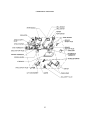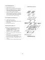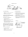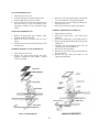
1
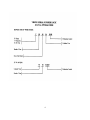
SERVICE MANUAL
FREE STANDING GAS RANGE
TABLE OF CONTENTS
Top Burner Ignitor Removal...........................
Spark Module Removal...................................
Indicator Light Removal..................................
Bake / Broil Thermostat Removal....................
Oven Ignitor Removal.....................................
Broil Gas Valve Removal.................................
Oven Gas Valve Removal.................................
Top Burner Valve Replacement........................
Pressure Regulator Removal............................
Convection Fan Removal.................................
Oven Burner Removal.....................................
Broil Burner Removal......................................
Broil Ignitor Removal.......................................
Indicator Light..................................................
Oven Light Switch...........................................
Oven Light Switch Removal............................
Oven Gasket Removal.....................................
Convection Fan Removal.................................
Oven Light Removal........................................
Grill Burner Removal.......................................
Grill Ignitor Removal.......................................
Griddle Thermostat Removal...........................
Trouble Shooting Guide....................................
Griddle Repaie Kit.(12") griddle......................
Griddle Repair Kit (24")...................................
Wiring Diagram (Rangetops)............................
Wiring Diagram (convection Ranges)...............
Viking Model Numbers................................... 2
Viking Serial Number logic............................. 3
Viking Product Warrenty................................. 4
Proximity to Side Cabinets Installation...........
6
Gas Connections............................................
7
Rangetop Cutout and Specifications...............
8
Range Leveling...............................................
9
Combustion of Gas........................................
10
BTU Requirements......................................... 12
Gas Conversion............................................... 13
I / R Broiler Spud (Orifice) Change..............
14
Surface Burner Adjustments............................ 15
Oven Burner Adjustments............................... 16
Grill / Griddle Burner Adjustment................... 17
Oven Temperature Calibration Chart................ 18
Oven Thermostat / Calibration.......................... 19
Silicon Carbide (Glow-Coil) Ignition............... 20
Door Removal.................................................. 21
Oven Door Assembly....................................... 22
Hinge and Logo Removal................................ 22
Door Hinge Removal...........................................22
Oven Door Parts..................................................22
Control Panel Removal..................................... 23
Landing Ledge Removal................................... 23
Component Location...........................................24
Top Burner Removal........................................ 25
2
25
25
26
26
26
26
26
27
27
27
27
28
28
28
28
28
28
28
29
29
29
29
30
34
35
36
37
NEW VIKING MODEL NUMBERS
RANGES AND RANGETOPS
V G R C
4 8 5
V-Viking
4 G Q D S S
Color
AL-Almond
Bk-Black
BU-Burgundy
EW-Euro White
FG-Forest Green
PL-Plum
SS-Stainless Steel
VB-Viking Blue
WH-White
G-Gas
SS-24" D
Standard Range (30"W)
SC-27" D
Convection Range (30"W)
RC-27" D
GG-Graphite
Convection Range (36"/48"W)
Gray
RT-24" D
LN-Linen
Rangetop
Width
30"
36"
48"
60"
D-Oven Door Window
Q-12" Wide Grill
0-Standard Oven
5-Convection Oven
G-Griddle
12" Wide
24" Wide
Number of Surface Burners
3
4
VIKING RANGE CORPORATION
PRODUCT WARRANTY
COOKING PRODUCTS
* 5 YEARS-OVEN TUBULAR BURNER (PART ONLY)
* 10 YEAR LIMITED WARRANTY-ANY PORCELAIN
OVEN OR PORCELAIN INNER DOOR PANEL
WHICH RUSTS THROUGH
FREE STANDING GAS RANGES
* 90 DAYS-GLASS, PAINTED, PORCELAIN AND
DECORATIVE ITEMS
* 1 YEAR FULL WARRANTY-COMPONENTS AND
ACCESSORIES
* 5 YEAR LIMITED WARRANTY-SURFACE BURNER,
GRIDDLE TUBULAR BURNER, GRILL TUBULAR
BURNER (PART ONLY)
* 10 YEAR LIMITED WARRANTY-ANY PORCELAIN
OVEN OR PORCELAIN INNER DOOR WHICH
RUSTS THROUGH
ELECTRIC WALL OVENS
* 90 DAYS-GLASS, POINTED, PORCELAIN AND
DECORATIVE ITEMS
* 1 YEAR FULL WARRANTY-COMPONENTS AND
ACCESSORIES
* 5 YEARS LIMITED WARRANTY-OVEN BAKE,
BROIL,OR CONVECTION HEATING ELEMENTS
* 10 YEAR LIMITED WARRANTY-ANY PORCELAIN
OR PORCELAIN INNER DOOR PANEL WHICH
RUSTS THROUGH
DUAL FUEL RANGES
* 90 DAYS-GLASS, PAINTED, PORCELAIN AND
DECORATIVE ITEMS
* 1 YEAR FULL WARRANTY-COMPONENTS AND
ACCESSORIES
* 5 YEAR LIMITED WARRANTY-SURFACE BURNER,
GRIDDLE TUBULAR BURNER, GRILL TUBULAR
BURNER, BAKE ELEMENT, BROIL ELEMENT, OR
CONVECTION COOK ELEMENT (PART ONLY)
* 10 YEAR LIMITED WARRANTY-ANY PORCELAIN
OVEN OR PORCELAIN INNER DOOR PANEL
WHICH
RUSTS THROUGH
WARMING DRAWERS
* 90 DAYS-PAINTED AND DECORATIVE ITEMS
* 1 YEAR FULL WARRANTY-COMPONENTS AND
ACCESSORIES
* 5 YEAR LIMITED WARRANTY-HEATING ELEMENT
VENTILATION PRODUCTS
* 90 DAYS-PAINTED AND DECORATIVE ITEMS
* 1 YEAR FULL WARRANTY-COMPONENTS AND
ACCESSORIES
* 2 YEAR LIMITED WARRANTY-BLOWER MOTOR
OR EXTERIOR VENTILATOR MOTOR
ELECTRIC RANGES
* 90 DAYS-GLASS, PAINTED, PORCELAIN AND
DECORATIVE ITEMS
* 1 YEAR FULL WARRANTY-COMPONENTS AND
ACCESSORIES
* 5 YEAR-ANY HALOGEN ELEMENT, BAKE
ELEMENT, BROIL ELEMENT, OR CONVECTION
COOK ELEMENT (PART ONLY)
* 10 YEAR LIMITED WARRANTY-ANY PORCEOAIN
OVEN OR PORCELAIN INNER DOOR PANEL
WHICH RUSTS THROUGH
KITCHEN CLEAN-UP
DISHWASHER
* 90 DAYS-PAINTED OR DECORATIVE ITEMS
* 1 YEAR FULL WARRANTY-COMPONENTS AND
ACCESSORIES
* 5 YEAR LIMITED WARRANTY-MOTOR/PUMP AND
WATER DISTRIBUTION SYSTEM COMPONENTS
* CIRCULATION PUMP
* DRAIN MOTOR/PUMP
* FILL VALVE
* LOWER WASH ARM
* TUBE TO UPPER WASH ARM
* UPPER WASH ARM
* 25 YEAR LIMITED WARRANTY-STAINLESS STEEL
TANK OR INNER DOOR LINER WHICH DEVELOPS
A
WATER LEAK
GAS RANGETOPS
* 90 DAYS -GLASS, PAINTED, PORCELAIN AND
DECORATIVE ITEMS
* 1 YEAR FULL WARRANTY-COMPONENTS AND
ACCESSORIES
* 5 YEAR LIMITED WARRANTY-SURFACE
BURNERS,
GRIDDLE TUBULAR BURNER, GRILL TUBULAR
BURNER (PART ONLY)
TRASH COMPACTORS
* 90 DAYS-PAINTED OR DECORATIVE ITEMS
* 1 YEAR FULL WARRANTY-COMPONENTS AND
ACCESSORIES
* 5 YEAR LIMITED WARRANTY-DRIVE SYSTEM
MOTOR
ELECTRIC RANGETOP
* 90 DAYS-GLASS, PAINTED, PORCELAIN AND
DECORATIVE ITEMS
* 1 YEAR FULL WARRANTY-COMPONENTS AND
ACCESSORIES
* 5 YEAR-ANY HALOGEN ELEMENT, BAKE
ELEMENT, BROIL ELEMENT, OR CONVECTION
COOK ELEMENT (PART ONLY)
DISPOSERS
* VCFW 1020 AND VBFW
* 7 YEAR FULL WARRANTY
* VCHW 1000 AND VBHW 1030
* 5 YEAR FULL WARRANTY
GAS WALL OVENS
* 90 DAYS-GLASS, PAINTED, PORCELAIN AND
DECORATIVE ITEMS
* 1 YEAR FULL WARRANTY-COMPONENTS AND
ACCESSORIES
5
PRODUCT WARRANTY (CONTINUED)
REFRIGERATION PRODUCTS
REFRIGERATION
* 90 DAYS-PAINTED OR DECORATIVE ITEMS
* 2 YEARS FULL WARRANTY
* 6 YEARS FULL WARRANTY ON SEALED SYSTEM
COMPONENTS
* COMPRESSOR
* CONDENSER
* DRYER/STRAINER
* EVAPORATOR
* CONNECTING TUBING
* 12 YEAR LIMITED WARRANTY-SEALED SYSTEM
COMPONENT (PARTS ONLY)
* COMPRESSOR
* CONDENSER
* DRYER/STRAINER
* EVAPORATOR
* CONNECTING TUBING
WINE COOLER
* 90 DAYS-PAINTED OR DECORATIVE ITEMS
* 2 YEAR FULL WARRANTY
* 6 YEAR FULL WARRANTYON SEALED SYSTEM
COMPONENT
* COMPRESSOR
* CONDENSER
* DRYER/STRAINER
* EVAPORATOR
* CONNECTING TUBING
* 12 YEAR LIMITED WARRANTY-SEALED SYSTEM
COMPONENT (PART ONLY)
* COMPRESSOR
* CONDENSER
* DRYER/STRAINER
* EVAPORATOR
* CONNECTING TUBING
ICE MAKER
* 90 DAYS-PAINTED OF DECORATIVE ITEMS\
* 2 YEAR FULL WARRANTY
* 6 YEAR FULL WARRANTY ON SEALED SYSTEM
COMPONENT
* COMPRESSOR
* CONDENSER
* DRYER/STRAINER
* EVAPORATOR
* CONNECTING TUBING
* 12 YEAR LIMITED WARRANTY-SEALED SYSTEM
COMPONENT (PART ONLY)
* COMPRESSOR
* CONDENSER
* DRYER/STRAINER
* EVAPORATOR
* CONNECTING TUBING
OUTDOOR PRODUCTS
GAS GRILLS
* 90 DAY-PAINTED, PORCELAIN, AND DECORATIVE
ITEMS
* 1 YEAR FULL WARRANTY
* 5 YEAR LIMITED WARRANTY-CAST IRON
BURNER
ASSEMBLIES, INFRARED ROTISSERIE BURNERS,
AND PORCELAIN GRILL GRATES
* LIFETIME WARRANTY-STAINLESS STEEL PART
WHICH RUST THROUGH
6
PROXIMITY TO SIDE CABINET INSTALLATION
1.
This range may be installed directly adjacent to existing 36" high base cabinets.
IMPORTANT- the top grate support MUST BE 3/8" above the adjacent base cabinet countertop. This may
be accomplished by raising the unit using the adjustment spindles on the legs. (The countertops CANNOT
be higher than 37 1/2" due to the high BTU burners.)
2.
The range CANNOT be installed directly adjacent to sidewalls, tall cabinets, tall appliances, or other side
vertical surfaces above 36" high. There must be a minimum of 6" side clearance from the range to such
combustible surfaced above the counter height.
3.
Within the 6" side clearance to combustible vertical surfaces above 36", the maximum wall cabinet depth must
be 13" and wall cabinets within 6" side clearance must be 18" above the 36" high countertop.
4.
Wall cabinets above the range must be a minimum of 36" above the range cooking surface for the full width of
the range.
7
GAS CONNECTIONS
The gas supply (service) line must be the same size or greater than the inlet line of the appliance. This range
uses a ½" I.D. NPT (Sch40) inlet. Sealant on all pipe joints must be resistive to Lp gas.
1.
2.
Manual Shut-off Valve:
This installer supplied valve must be installed
in the gas service line ahead of the appliance
and regulator in a position where it can be
reached quickly in the event of an emergency.
Pressure Regulator:
a) All heavy-duty, commercial-type cooking
equipment must have a pressure regulator on
the incoming service line for safe and efficient
operation, since service pressure may fluctuate
with local demand. External regulators are not
required on this range, because a regulator is
built into each unit at the factory. UNDER NO
CONDITION BYPASS THIS BUILT-IN
REGULATOR.
b) Any conversion required must be performed
by your dealer or a qualified licensed plumber
or gas service company. Please provide the
service person with this manual before work
si
started on the range.
( GAS CONVERSIONS ARE THE
RESPONSIBILITY OF THE DEALER OR
END USER.)
c) This range can be used with Natural gas or
LP/Propane. It is shipped from the factory
adjusted for use with natural gas. The orifice
hoods must be screwed snug when
LP/Propane is used.
(See LP/Propane
conversion).
d) Manifold pressure should be checked with a
manometer, natural gas requires 5.0"WC and LP
gas requires 10.0"WC. Incoming line pressure
upstream from the regulator must be 1.0"WC
higher than the manifold pressure in order to
check the regulator. The regulator used on this
range can withstand a maximum input pressure
3.
of ½ PSI (14.0" WC). If the line pressure is
in excess of that amount, a step-down
regulator will be required.
8
e) The appliance, its individual shut-off valve,
and pressure regulator must be disconnected
from the gas supply piping system during any
pressure testing of that system at pressures in
excess of 1/2psig (3.45kPa).
f) The appliance must be isolated from the gas
supply piping system by closing its individual
manual shut-off valve during any pressure testing
of the gas piping system at test pressures equal to
or less than ½ psig (3.45kPa).
Flexible Connections:
a) If the unit is to be installed with flexible
couplings and/or quick-disconnect fittings, the
installer must use a heavy duty, A.G.A. design
certified commercial flexible connector of at least
½" ID NPT ( with suitable strain reliefs) in
compliance with ANSI Z21.69.
b) In Canada: CAN 1-6. 10-88 metal
connectors for gas appliance and CAN 1-6.9
M79 quick disconnect devices for use with gas
fuel.
RANGETOP CUTOUT and SPECIFICATIONS
1.
Gas Line Requirements:
a. Gas pipe size should be 3/4" (½" inside diameter)
b. Gas pipe should be 3" or less from floor and 6" from left to center of unit to allow for the
flex line.
i.e.
30" range 6"-15" from left
48" range
6"-24" from left
36" range 6"-15" from left
60" range
6"-30" from left
If it is higher than 3" from the floor, the range will not fit flush against the wall and
The shutoff valve will not be accessible.
2.
Electrical Requirements: Gas ranges, gas rangetops, and Gas cooktops require a 120 volt
electrical outlet (GFI ground fault outlet not recommended).
a. 3" or less from the floor and 6" from the right to center of the unit.
i.e.
30" range 6"-15" from right
48" range
6"-24" from right
36" range 6"-18" from right
60" range
6"-30" from right
9
RANGE LEVELING
Careful leveling of the range is critical not only to
performance, but also to allow the alignment of
oven doors and drip tray. Closely follow the
procedures below to ensure proper performance
and appearance of the range. The range being
even slightly out of level will significantly
contribute to misalignment of oven doors.
1.
If the floor is smooth and level, level the unit
with the screw thread of the legs. Set the high
corner of the range so that the top of the grate
support is 3/8" above the countertop, and level
the range to the high corner.
2.
If the floor is uneven or has a decided slope,
level the unit with metal shims, as the
adjustment required may exceed the thread
available in the leg.
3.
Proper and careful leveling of the range is
necessary for proper alignment of the oven
doors.
The body of the range does not have a rigid frame
to hold it into one position. This non-rigid
framework allows the range to shift with un-level
floors or slanted cabinets.
Moving any one of the adjustable leveling legs up
or down will shift the range body. Use the
vertical line between the edge of the door and the
left side trim or center trim on the 2 door models
to adjust the leveling legs.
When adjusted properly this space will be
uniform from the top to the bottom of the
door. The bottom corner of the end panel
will move in or out. Adjust this lower corner
to have an equal space from the top to the
bottom of the door.
Increasing the length of the right front leveling
leg will raise the right front corner of the
range, moving the top of the door to the left.
Lowering the right front leveling leg will
cause the top of the door to move to the right.
Using the left front leveling leg will give you
the opposite effect. Raising the left front
corner will move the top of the door to the
right. Lowering the corner will move the top
of the door to the left. The rear leveling legs
will also have an effect on the door alignment.
A. Right Side
Front / Back
Adjustable Legs
B. Left Side
Front / Back
Adjustable Legs
10
4.
After the range is properly leveled , the drip
tray handle may be aligned by loosening the
screws and adjusting the handle horizontally
within the limits provided by the slotted
screw holes.
5.
A carpenters’ spirit level should be placed
across the top of the range and the unit
leveled front-to back, side-to side and
vertically. If it is not level, burner
combustion may be erratic, liquid or semiliquid batters will cook at an angle, and the
unit may not function efficiently.
COMBUSTION OF GAS
A.
B.
C.
D.
The Meaning of Combustion - When oxygen
acts with a substance to produce large amounts of
heat rapidly (and usually light), the process is
called combustion or burning.
Requirements for Combustion - Three things
needed for combustion to take place are fuel,
oxygen (air) and heat (temperature). All must be
present. Take away any one of the three and
burning will stop. Gas ignition temperature is
approximately 1100 - 1200 degrees Fahrenheit.
Basic Chemistry of Combustion - Combustion
of gas is a chemical reaction between fuel gas and
oxygen. The basic elements of common fuel
gases are hydrogen (H) and Carbon (C). When
hydrogen burns, water vapor
(H2O) is
produced. Complete burning of carbon in fuel
gases form carbon dioxide (C02). Complete
combustion produces harmless carbon dioxide
(C02) and water vapor (H20).
Water is produced as a vapor in the burning of
gas.If the flue products remain hot enough, water
is discharged as vapor to the outside through vent
system. If the flue products should become cool,
as in an air conditioned room, this water vapor
will condense out as a liquid on any cooler
surface. The temperature at which water forms
from vapor is known as the dew-point.
Controlled Combustion - Controlled combustion
takes place when fuel gas and air are
supplied at proper rates to assure complete
combustion (burning) of the gas in a steady
flame. When a gas appliance is operating
properly, burning starts at
the burner ports.
Gas flow is controlled by a gas orifice size and by
gas pressure upstream of the orifice. Burners
which have some air premixed with the gas before
it passes through the BURNER
PORTS
are called “blue flame” burners. This air added to
the gas is called primary air. The rest of the air
required for complete combustion is supplied
to the burner flames in the COMBUSTION
CHAMBER and is called SECONDARY AIR.
Adjustments of gas rate and primary air provide
the key to obtaining stable, blue flames on the
burner using primary air. AIR SHUTTERS or
other devices provide control of primary air.
Proper amounts of primary and secondary air are
needed for quiet and efficient appliance operation
E.
F.
G.
11
and for complete combustion of the gas. Size of
the inlet openings and flue outlets control
secondary air flow.
Explosive Combustion - An explosion is simply
very rapid burning which is not under control.
Limits of Flammability - Not all air-gas
mixtures will burn. Mixtures with zero to four
percent natural gas in air are to lean to burn.
Mixtures of four to fourteen percent natural gas in
air can burn with a controlled flame.
Flammability Limits are of interest to those
dealing with problems and everyday operations in
the gas industry. For example consider,
FLASHTUBE ignition of rangetop burners. A
gas-air mixture from the burner head passes
through a charge port into the open end of the
flashtube. This mixture is too rich to burn
without secondary air, but some air also enters
the flashtube at the entrance. The additional air
causes the mixture to become leaner to a
composition that is flammable. When the mixture
travels down the tube to point of ignition, the
flame will carry back from the lighter to the
charge port and light the gas at the burner. If
the mixture in the flashtube has too
much gas (too rich) or has too much air (too lean),
the burner will not light.
Flammability Limits also enter the picture when
primary air adjustments are made on burners. For
example, Infra-red (radiant) burners usually
operate with about 100 percent primary air. In
other word the gas air mixture in the burner head
contains all the air ideally required for complete
combustion. If too much primary air is used, the
mixture may become too lean and fall outside the
lower flammability limit and it will not burn on
the burner surface.
Unburned gas should not be allowed to collect in
combustion chambers or confined spaces because
gas-air mixture within the flammability limits will
explode if ignited.
Incomplete Combustion - Causes and Effects
To obtain complete combustion enough air must
be supplied to the process. This air must have a
Reasonably normal oxygen content. Complete
burning of gas produces harmless carbon dioxide
and water vapor. If not enough air is supplied
other products will form. Some of these products
are harmful, especially carbon monoxide.
H.
COMBUSTION OF GAS (CONTINUED)
I.
BURNER COMPONENTS
It is vital that an appliance venting system do its
job. The importance of providing enough fresh
Gas Orifice - An opening or hole, regulates or
air to the room in which and appliance is
limits the amount of gas flowing to a burner. Gas
located can not be stressed too strongly.
flow rate (volume) depends on the size of the
orifice (hole) and gas pressure at the inlet of the
Carbon monoxide is a toxic gas. It can cause
orifice.
death if enough of it is inhaled. This gas has no
odor, color or taste, so that it cannot be detected
by bodily senses. Inhaled carbon monoxide is
absorbed into the blood. It combines with
hemoglobin in the blood to a much greater extent
than oxygen and
remains in the blood longer
than oxygen does. In doing so, it acts to reduce
the oxygen-carrying function of the blood. Thus,
a person exposed to carbon monoxide can die lf a
lack of oxygen.
Air Shutter - This is used to adjust the size of
Carbon monoxide is only one product of
the openings to control primary air flow.
incomplete combustion. ALDEHYDES, another
class of compounds, also may be formed in
Venturi Throat - A section in a pipe or a burner
incomplete combustion. While carbon monoxide
body that narrows down and then flares out again.
is odorless, Aldehydes have a sharp, penetrating
This neck helps maintain a more constant primary
odor. They are readily detected be smell, even at
air injection.
very low concentrations. The odor of aldehydes
differs from odorants added to natural gas and the
Mixing Tube - Serves to carry the air-gas mixture
two should not be confused. The absence of
from the venturi throat to the burner head.
aldehydes does not assure that carbon monoxide
is not present. However, if the odor of aldehydes
Burner Head - Contains the burner ports, and
is present, then carbon monoxides almost always
provides uniform distribution of the air-gas
will be present, aldehydes themselves also are
mixture to those ports.
toxic.
GAS BURNER OPERATION - A gas burner is
Burner Ports - Distributes flames to provide good
a device to burn gas under control to produce
heat transfer. They spread the flames so they can
useful heat.
be reached by secondary air. They provide
Primary air is brought into the burner from
stable, blue flames.
outside the appliance at atmosphere pressure.
The gas jet streaming from the orifice draws or
injects primary air into the burner.
PRIMARY AIR: Air which is mixed with gas
before the gas leaves a burner port to burn.
SECONDARY AIR: Air externally supplied to
a burner flame at the point of combustion.
12
VIKING RANGE BTU REQUIREMENTS
Determine the size of piping or tubing required for the two stage LP Gas installation shown.
Total of the first stage piping length equal 26 feet; first
stage regulator setting is 10 psig. From “aa” to “a”,
demands equal 338,000 BTU/hr., use ½" pipe, ½"
tubing, or ½" T plastic pipe. (This is determined by
using a gas range with a total of 65,00 BTU usage. See
below for the BTU ratings of the Viking ranges.)
Total BTU’s required for each Viking range by model
number.
VGR30
VGR36-4G
VGR36-6B
VGR48-4G
VGR48-6G
VGR48-8B
Total second stage piping length equal 50 feet.
From a to b, demand = 338,000 BTU/hr, use 1" pipe.
From b to c, demand = 138,000 BTU/hr, use 3/4" pipe
or 7/8" tubing.
From c to d, demand = 100,000 BTU/hr, use ½" pipe or
1/4" tubing.
From d to e, demand = 35,000 BTU/hr, use ½" pipe or
½" tubing.
From b to f, demand = 200,000 BTU/hr, use 3/4" pipe.
From c to g, demand = 38,000 BTU/hr, use ½" pipe or
5/8" tubing.
From d to n, demand = 65,000 BTU/hr, use ½" pipe or
5/8" tubing.
75,000
103,000
128,000
130,000
145,000
160,000
VGSS300
VGSC305
VGRC365
VGRC485
VGRC605
105.000
108,000
138,000
183,000
203,000
The size of the LP supply tank should be calculated by
the total number of BTU requirements of the gas
appliance.
The pressure supplied from the LP supply tank should
be between *12 WCI and *14 WCI. The regulator on
your Viking range will supply a steady *10 WCI to the
manifold.
*WCI - Water column inches.
13
NATURAL GAS TO LP/PROPANE CONVERSION INSTRUCTIONS
This product is manufactured and adjusted for operation with natural gas as shipped from the factory. To operate with
LP/Propane gas, the following adjustments must be made.
A pressure regulator is located in the left rear corner of the burner box. To gain access to the pressure regulator,
remove the two left grates, two burner bowls, and the left grate support. Convert the regulator by removeng the
cap marked “NAT” and reverse it to read “LP”. Be sure not to disturb or remove the spring beneath the cap.
ILLUSTRATION # 1
To convert surface, griddle, grill, bake, and tubular burners to LP/Propane, turn the burner orifice hoods
clockwise until they become snug against the internal LP/Propane pin orifice, (See Illustration #2). After
adjusting the oven burner orifice hoods (Illustration #3, Item “3") for LP gas, it may be necessary to shift
the burner from position “4" to position “5" (Illustration #3) on the burner mounting bracket. This will
properly position the orifice hood in the burner venturi.
ILLUSTRATION #2
ILLUSTRATION #3
The orifice spud for INFRARED broilers has to be physically changed. Remove the #47 orifice spud and
replace with the #56 orifice spud (see Illustration #2) that is attached to the infrared broil burner gas supply
tubing. Attach the natural gas #47 orifice spud to the gas supply tubing for future use should the product need
to be reconverted to natural gas. Note: Changing the infrared fixed (spud) orifice must be completed before
the range is placed into the space provided.
14
INFRARED BROILER ORIFICE SPUD CHANGE
The orifice change is accomplished by:
1.
2.
3.
4.
5.
6.
7.
Turning the gas off at the shut-off valve
Removing the range from the cabinets
Remove the back guard from the range
Locating the gas supply line at the end of the broiler venturi
Remove and replace the orifice spud located at the end of the gas supply tube
Reverse steps 3-2-1
Check the operation of the infrared broiler
15
SURFACE BURNER ADJUSTMENTS
To gain access to the surface burner adjustments:
b) Close the air gap to prevent a noisy flame
that lifts off the burner ports.
8. Turn the surface burner off.
9. Replace the drip tray.
10. Remove the grate support and burner bowls.
11. Tighten the air shutter screws “B”.
12. Replace the grates, burner caps (if applicable),
burner bowls and grate supports.
13. Relight each burner and turn to the low flame
setting.
14. Remove knob.
15. Insert a narrow, flat blade screwdriver into the
hollow shaft of the surface burner valve, and
engage the slotted low flame adjustment screw.
The low flame should be a small flame the comes
just to the edge of the burner rim. Rotate the
adjusting screw “E” clockwise to lower the flame
or clockwise to increase the flame. Turn the
burner off and relight several times, turning to the
low position. The flame should light at every port
each time. Readjust as
needed.
1. Remove the grates, burner caps, burner bowls, and
grate supports.
2. Locate the air shutter “A” and loosen screw “B” that
holds the air shutter in place.
3. Remove the drip tray, allowing you work space to
adjust the orifice hood “C”.
4. Replace the grate support and burner bowls (this
allows for correct air flow, as in normal use).
5. Light each burner by rotating the burner valve shaft
“D” to high position.
6. Use a ½" deep socket to adjust the orifice hood on
Nat. gas only (LP tighten to fixed orifice); turn
clockwise to decrease the flame and counter
clockwise to increase the flame.
7. With the proper flame height, adjust the air shutter
“A” to obtain a blue flame (with no yellow tipping)
that sits on the burner at the burner ports.
a) Open the air shutter gap to eliminate
yellow tipping.
BURNER ASSEMBLY
LOW FLAME ADJUSTMENT
16
OVEN TUBULAR GAS BURNER ADJUSTMENTS
Check the gas supply, and set the regulator to the proper supply of gas. A properly adjusted burner should be stable and
quiet. The flame should have a sharp, well defined blue inner cone with no yellow tipping. The flame should also be
stable and uniform with no flames lifting off the burner ports.
To gain access to the oven burner adjustments:
1.
2.
3.
4.
5.
6.
Recheck the orifice hood (illustration #1, item
“3") adjustment for proper gas flow.
7. Turn the thermostat control to off.
8. Tighten the air shutter set screw (illustration #1,
item “2").
9. Relight each burner and observe the flame for
proper adjustments. If necessary, repeat the
above.
10. Turn the convection fan on and observe that the
flame does not lift off the burner ports, readjust
the air shutter gap with the convection fan
running.
11. Replace the kick plate.
Remove the kick plate - remove screw from each
side of the kick plate and tilt the top of the kick
plate forward.
Locate the air shutter (illustration#1, item ”1") and
loosen the set screw (illustration #1, item ”2") that
holds the air shutter in place.
Light the burners by rotating the thermostat to a
baking temperature.
Using a ½" open end wrench, adjust the orifice
hood (illustration #1, item ”3") to obtain a sharp
well defined blue inner cone approximately ½"
long. The flame should be contacting the burner at
each port opening. THE FLAME SHOULD NOT
EXTEND INTO THE OVEN BOTTOM VENT
SLOTS.
With a proper flame height, adjust the air shutter
(illustration #1, item “1") to obtain a blue flame
with no yellow tipping that contacts the burner at
the burner ports.
a) Open the air shutter gap (illustration#1,
item ”1") to eliminate yellow tipping.
b) Close the air shutter gap (illustration #1,
item ”1") to prevent a noisy flame that
lifts off the burner ports.
IMPORTANT: Conditions that cause odors:
a).
b).
c).
Floating flames are lazy looking and not have a
well defined inner cone. They are long, ill
defined, quiet flames that sometimes lift
completely off the ports and cause a strong and
pungent odor.
Lifting flames are well defined, hard and noisy
that lift completely off the ports.
An orifice that is out of line with the burner
venturi.
ILLUSTRATION #1
17
GRILL / GRIDDLE BURNER ADJUSTMENT
GRILL ( Item “A” )
GRIDDLE ( Item “B” )
1.
The grill burner orifice and air shutter are located
beneath the front end of the grill assembly. To
gain access to the adjustments, remove the grill
grate, grate support, flame spreader and the burner
shield.
2. Remove the screw at the front and rear of the
burner.
3. Lift the burner off the orifice and locate the air
shutter adjustment screw at the end of the burner.
4. Loosen the screw and adjust the air shutter to the
desired setting (for natural gas open shutter
approximately ½"; for LP/Propane gas open the air
shutter approximately 9/16").
5. Tighten the screw, then replace burner on the
orifice.
6. Check flame for desired height before replacement
of the above parts.
7. The flame adjustments are the same as the surface
burners. Use a ½" deep socket to adjust the orifice
hood on natural gas only (LP tightened to the fixed
orifice); turn clockwise to decrease the flame and
counter clockwise to increase the flame.
1.
2.
3.
4.
5.
6.
18
To gain access to the burner orifice and air shutter,
remove grates and grate supports located on either
side of the griddle. Lift and remove griddle plate.
Carefully remove ignitor and put to the side.
Remove the metal plate located below the burner.
Remove the screws at the front and rear of the
burner remove the burner tube and locate the air
shutter adjustment screw at the end of the burner
tube.
Flame adjustments are the same as the grill - see #4
and #7 under grill.
Replace the griddle plate.
OVEN TEMPERATURE CALIBRATION
A.
Monitor house voltage during test.
1.
B.
Monitor igniter (glo-coil) current during test.
1.
C.
Must maintain 3.4 amps or greater.
From____________to_____________
Monitor voltage across the thermal valve connectors.
1.
D.
Must maintain at 117 VAC
From ___________to____________
Must be between 3.03 and 3.3 volts A.C.
From ___________to_____________
Check gas pressure at the manifold (burner orifice). Light a burner during test to
equalize pressure.
1.
2.
3.
Check to make sure 1/2" Inside Diameter (ID) supply line to the product.
NAT____________WCP must be 5" WCP.
L.P._____________WCP must be 10" WCP.
Supply pressure from the meter or L.P. tank must be at least 6" WCP for natural gas or 11"
WCP for L.P. gas. Pressure should never exceed 14" WCP or 1/2 PSI.
E.
Be sure the thermostat bulb is straight and properly spaced from the oven liner. The sensor bulb
clips should be in place.
F.
Place a weighted thermo-couple in the center of the oven cavity.
G.
Set oven temperature control to 350*F. Oven temperature should reach 350*F in 10 minutes.
H.
Cycle oven 5 times: Average 3rd, 4th and 5th cycles. Temperature is acceptable if the
average is 350*F -15F +25*F.
TEMPERATURE;
Conventional Oven
Cycle
1
2
High (XX) (XX) (
Low
(XX) (XX) (
I.
3
) (
) (
4
) (
) (
5
)
)
(
(
Average
)
)
For convection test lower temperature to 325*F. Pre heat oven with convection fan on.
TEMPERATURE:
Convection Oven
Cycle
1
High (XX)
Low
(XX)
(
(
2
) (
) (
3
)
)
Average
(
)
(
)
J.
On conventional baking place pans in the center of the oven.
K.
On convection baking place pans on rack positions 2 and 4.
L.
Uneven temperatures left to right in oven.
1. Check air shutter adjustment; sharp blue flame, no yellow tipping.
2. Check orifice hood adjustment.
19
OVEN THERMOSTAT
The oven thermostat maintains the correct oven
temperatures in the bake and broil operations.
In bake operation, thermostat contacts close completing
the bake circuit through the bake ignitor, and bake gas
valve to neutral.
In broil operation, thermostat contacts close completing
the broil circuit through the broil ignitor and broil gas
valve to neutral.
The thermostat contacts can be checked for continuity
by using a continuity tester or an ohmmeter set to the
low ohms range. Power to the oven must be turned off
and the thermostat wiring removed when checking the
contacts for continuity. Access to the thermostat
contacts can be made by removing the control panel.
Replace the thermostat if the switch contacts are
defective.
THERMOSTAT CALIBRATION
Use the Oven Calibration Chart to determine the need
for a calibration. (See the preceding page.)
1.
2.
3.
4.
5.
Remove the thermostat control knob.
Remove the silicone gel from thermostat shaft.
Turn adjusting screw counter clockwise to
increase the temperature. (1/4 turn equals 37*F.
DO NOT TURN MORE THAN 1/4 TURN.)
Turn adjusting screw clockwise to decrease the
temperature. (1/4 turn equals 37*F. DO NOT
TURN MORE THAN 1/4 TURN.)
Follow the instructions on the Oven Calibration
Chart to calibrate oven temperature. (See the
preceding page.)
20
SILICON CARBIDE (GLO-COIL) IGNITION
BAKE AND BROIL IGNITERS
The bake and broil igniters are mounted to the bake and
broil burner and ignite the gas flowing into the burner.
During a bake or broil operation, current flows through
the ignite, gas valve and thermostat to neutral. As the
ignite starts heating and glowing, its internal resistance
decreases allowing more current to flow through the
bake or broil circuit. When the circuit current reaches
approximately 3.2 to 3.6 amps, the bi-metal arm in the
gas valve flexes, opening the valve, allowing gas to
flow to the burner when it is ignited by the glowing
ignite. The ignite will glow anytime the bake or broil
burners are in operation and cycle on and off with the
thermostat cycling contacts.
GAS VALVE
The bake and broil gas valves supply gas flow to the
bake or broil burners. The valve contain a bi-metal arm
attached to the valve seat and is wound with a small
electric heater coil. When a current range of
approximately 3.2 to 3.6 amps flows through the bake
or broil circuit the bi-metal arm is heated causing it to
flex or bend, allowing gas to flow to the burner where it
is ignited by the burner ignite. An amperage reading
less than 3.2 will cause the gas valve to partially open,
resulting in a reduced gas flow to the burners.
A continuity test can be made to check the bi-metal arm
heater by using an ohmmeter set to the low ohm range
or a continuity tester. Access to the bake valve can be
made by removing the access panel. The broil gas
valve is located on the right side of the burner box
flueway and the bake valve is located on the left side of
the oven burner box. Power to the oven must be shut
off and the gas valve wiring removed.
The ignite can be checked for continuity by using an
ohmmeter set to the Rx10 range. Remove the ignite
from the burner and disconnect the ignite wiring.
Attach one meter lead to each ignite wire. A resistance
of several hundred ohms may be indicated and may
vary with each ignite. The main purpose of this test is
to see if the ignite is open internally. The ignite may
still be defective even though continuity is indicated
and it glows when the oven is set for a bake, broil or
clean function. A more exact test is to measure the
ignite current with the oven operating. An ammeter
should be inserted in series with one lead of the ignite
or any amprobe attached to the of the ignite will check
the amount of current flowing through the ignite circuit.
With the oven turned on and the ignite glowing red,
a current reading of approximately 3.2 to 3.6 amps
should be indicated.
Attach the meter or tester leads to the two gas valve
terminals facing the rear of the oven. A low ohms
reading or continuity should be indicated. Repeat the
same test on the two gas valve terminals facing the
front of the oven . If infinite ohms or an open heater
coil is indicated on either set of terminals the complete
gas valve must be replaced.
21
DOOR REMOVAL
1.
Open the door approximately 15* to 20* then
slowly pull upward until the door stop (A) pops
out of the door socket. Gently close the door until
the door stops rest against one of the stop notches
(C). Slide the door up until completely free of the
hinge arms.
When the door stops pop out of the door too soon
the door will not slide off. When this happens:
a) Lower the door until the door stops
disappear into the door;
2.
A. DOOR (Vertical adjustment screw)
B. DOOR STOP (Holds hinge in place while
removing or replacing the door)
C. DOOR HINGE SPRING (Color denotes
part number)
22
b) Grasp the door near the lower end;
c) Place your thumbs over the door socket
openings to prevent the door stops from
popping out;
d) Hold the door stops in the door while
sliding the door up approximately inches;
e) Release the door stops and gently close
the door until the door stops rest against
one of the stop notches.
To replace the door, place the hinge arms into the
door sockets. Slide the door down close to the
door stops and release the pressure from the stop
notches. Slowly lower the door down completely
allowing the door stops to retract into the door
socket.
OVEN DOOR ASSEMBLY
1.
2.
3.
4.
5.
6.
7.
Remove oven door and put on a protected table or
counter top. (See oven door removal.)
Remove screws securing the door panel to the door
liner and remove the panel from the liner.
Remove the inner baffle, the window trim and the
glass window from the door panel.
The door handle is mounted to the door panel and
can be removed by removing the four (4) screws.
Remove the insulation plate and insulation from
the liner.
Remove the screws securing the window brackets
to the door liner and remove the brackets.
Remove the door window retainer and remove
window assembly.
3.
4.
DOOR HINGE REMOVAL
1.
2.
3.
4.
5.
HANDLE and LOGO REMOVAL
1.
2.
Door handle is mounted to the door panel and can
be removed by removing four (4) screws.
Remove the two (2) cap nuts securing the logo to
the outer door panel.
Remove door. (See door removal.)
Remove screws securing the door panel to the door
liner and remove panel form the liner.
6.
Remove door. (See oven door removal.)
Remove oven racks, rack supports, oven bottom
and inner side wall.
Remove two (2) screws securing the hinge cover to
the oven side wall.
Open the hinge and lock in the most open position.
Remove the lower and upper Phillips head screws
(located behind the oven gasket) securing the hinge
to the front frame.
Remove the hinge to the inside of the oven by
pulling through the hinge slot.
OVEN DOOR PARTS
A.
B.
C.
D.
E.
F.
G.
H.
J.
Logo
“J” molding
Door Handle Bracket
Door Handle
Outer Door Glass Retainer
Heat Baffle
Insulation (32 ½" x 16 7/8")
Inner Door Glass Retainer
Inner Door Glass
K.
L.
M.
N.
O.
#.
#.
P.
23
Door Glass Seal
Inner Door Liner With Window
Insulation Retainer With Window
Outer Door Glass
Outer Door Panel With Window
Upper Door Brace (Used on 36" models only)
Lower Door Brace ( Used on 3 6" models only)
Complete Door Assembly With Window
CONTROL PANEL and LANDING LEDGE REMOVAL
CONTROL PANEL REMOVAL
LANDING LEDGE REMOVAL
1.
Shut off power to the unit.
1.
Shut off power to the unit.
2.
Remove all top burner and grill knobs.
2,
remove the control panel.
removal.)
3.
Remove lower bezel screw from the second burner
control from each end of the control panel.
(Remove lower bezel screw from grill control on
grill models.)
3.
Remove grates, burner bowls and grate supports.
4.
Remove griddle and grill grates and grate supports.
(See control panel
4.
Remove two decorative screws at both ends of the
control panel.
5.
Remove the screws along the back of the landing
ledge.
5.
It is not necessary to remove bezels.
6.
Remove the two (2) screws at each end of the front
of the landing ledge.
7.
Remove the landing ledge.
24
COMPONENT LOCATION
25
TOP BURNER REMOVAL
BURNER BOX SECTION
1.
2.
3.
4.
5.
Shut off power to the oven.
Remove grates, burner bowls and grate supports.
Remove the phillip head screw near the burner
head securing the burner to the burner support.
Lift the burner and venturi assembly and remove
the wire from the bottom of the ignitor.
Both burner assemblies (front and read) can be
removed together by removing one (1) screw at the
rear of the burner support, remove both ignitor
wires and lift the burner support assembly.
TOP BURNER IGNITOR REMOVAL
1.
2.
3.
4.
Shut off power to the oven.
Remove grate and burner bowl.
Remove two (2) screws securing the ignitor to the
burner support.
Disconnect the ignitor wire.
SPARK MODULE REMOVAL
NOTE: FOUR BURNER MODELS WITH OR
WITHOUT A GRIDDLE USE ONLY ONE
(1) SPARK MODULE; FOUR (4)
BURNERS WITH A CHAR GRILL
REQUIRES TWO (2) SPARK MODULES.
1.
2.
3.
4.
Remove left and right grates, burner bowls and
grate supports.
Remove two (2) screws securing the spark module
cover, using care not to damage wiring.
Disconnect the wiring. (When replacing module
cover, do not forget to ground green wire to
chassis.)
For wiring sequence see wiring schematic section.
26
INDICATOR LIGHT REMOVAL
1.
2.
3.
4.
Shut off power to the unit.
Remove the control panel. (See control panel
removal.)
Disconnect the wiring from the indicator light.
Push the indicator light out of the control panel.
BAKE/BROIL THERMOSTAT REMOVAL
1.
2.
3.
4.
5.
6.
7.
Shut off power to the unit.
Remove the control panel. (See control panel
removal.)
Remove the two (2) clips securing the thermostat
bulb to the inner back wall.
Remove the left side grates, burner bowls and
grate supports.
Carefully pull the capillary tube out of the oven
cavity.
Disconnect the thermostat wiring one lead at a
time and connect to the appropriate terminal on the
replacement thermostat.
Remove two (2) screws mounting thermostat to
the control panel.
OVEN IGNITOR REMOVAL
1.
2.
3.
4.
5.
6.
Shut off power to the oven.
Remove oven door. (See oven door removal.)
Remove the lower access panel below the oven
door by removing two (2) mounting screws on
either side under the oven door hinges.
Disconnect the wire leads to the ignitor.
Remove the oven burner. (See oven burner
removal.)
Remove two (2) screws securing the ignitor to the
burner and remove the ignitor.
NOTE: CHECK ALL CONNECTIONS FOR LEAKS
USING A SOAP SOLUTION AFTER INSTALLING
THE REPLACEMENT VALVE.
OVEN GAS VALVE REMOVAL
1.
2.
3.
4.
BROIL GAS VALVE REMOVAL
1.
2.
3.
4.
5.
6.
Shut off power to the oven.
Shut off gas supply to the oven.
Remove right side grates, burner bowls and grate
supports.
Disconnect the wire leads to the broil valve
connecting leads to replacement valve.
Disconnect the gas supply tubing from the gas
valve.
Remove two (2) screws securing the gas valve to
the mounting bracket.
5.
6.
7.
Shut off power to the oven.
Shut off gas supply to the oven.
Remove the oven door. (See oven door removal.)
Remove the lower access panel below the oven
door by removing two (2) mounting screws on
either side under the door hinges.
Disconnect the wires leads to the gas valve.
Disconnect the gas supply tubing to the gas valve.
Remove two (2) screws securing the gas valve to
the mounting bracket.
NOTE: CHECK ALL CONNECTIONS FOR LEAKS
USING A SOAP SOLUTION AFTER INSTALLING
THE REPLACEMENT VALVE.
27
TOP BURNER VALVES
VALVE REPLACEMENT
OVEN BURNER REMOVAL
1.
Remove the control panel. (See control panel
removal.)
Remove the lower valve blot and gasket.
Lift the valve from the manifold.
1.
2.
3.
NOTE: CHECK ALL CONNECTIONS FOR LEAKS
USING A SOAP SOLUTION AFTER INSTALLING
THE REPLACEMENT VALVE.
4.
5.
6.
2.
3.
PRESSURE REGULATOR REMOVAL
1.
2.
3.
4.
5.
Shut off power to the oven.
Shut off gas supply to the oven.
Remove the left side grates, burner bowls and grate
supports.
Disconnect the gas supply to the oven.
Remove the regulator with a pipe wench turning
counter clock wise. (Secure the manifold with
another wrench before turning.)
NOTE: CHECK ALL CONNECTIONS FOR LEAKS
USING A SOAP SOLUTION AFTER INSTALL
REPLACEMENT REGULATOR. USE SEALANT
ON ALL PIPE JOINTS. SEALANT MUST BE
RESTIVE TO L.P. GAS. DO NOT USE THREAD
TAPE.
CONVECTION FAN REMOVAL
1.
2.
3.
4.
Shut off power to the unit.
Remove the control panel. (See control panel
removal.)
Disconnect the wiring from the fan switch.
Push the fan switch out of the control panel.
28
Shut off power to the oven.
Remove the oven door. (See oven door removal.)
Remove the lower access panel below the oven
door by removing two (2) mounting screws on
either side under the oven door hinges.
Disconnect the ignitors.
Remove two (2) screws securing the oven burner.
Remove the oven burner pulling forward until the
burner is free. (Be sure to align rear tab of the
burner with the mounting bracket in the oven when
replacing the burner.
INFRARED BURNE
terminals and turn the oven on to bake operation. If
voltage is present at the indicator terminals or the tester
lights up, and the indicator does not light, replace the
indicator.
OVEN LIGHT SWITCH
The oven light switches are mounted in the control
panel. The light switch can be checked for continuity
by using an ohmmeter set to the low ohms range or a
continuity tester.
Access to the switch can be made by removing the
control panel. Disconnect the wires from the switch.
Attach the meter or tester leads to the switch terminals.
Continuity or low ohms should be indicated when the
switch contacts are closed and no continuity or infinite
ohms indicated when the switch contacts are open. If
the switch fails this test, it must be replaced.
BROIL BURNER REMOVAL
1.
2.
3.
4.
5.
6.
7.
8.
9.
10.
Shut off power to the unit.
Shut off the gas supply.
Move the range out of the opening.
Disconnect the gas supply.
Remove the four (4) screws attaching the rear vent
and remove the vent. (Backguard, high shelf or
island trim.)
Remove the large pal nut securing the broiler to
the supply tubing and the spud assembly.
Remove the oven door. (See oven door removal.)
Remove two (2) broil ignitor mounting screws and
remove the ignitor from the broil burner.
Remove the broil burner mounting screws securing
the burner to the oven cavity.
Remove the broil burner.
OVEN LIGHT SWITCH REMOVAL
1.
2.
3.
4.
OVEN GASKET REMOVAL
1.
2.
3.
BROIL IGNITOR REMOVAL
1.
2.
3.
Shut off power to the unit.
Remove the control panel. (See control panel
removal.)
Disconnect the wires from the switch.
Push the switch forward and out of the control
panel.
4.
Shut off power to the oven.
Remove the two (2) broil ignitor mounting screws
and pull the ignitor leads into the oven cavity.
Disconnect the wire leads.
Remove the oven door. (See oven door removal.)
Open the hinge to the broil position.
Loosen the upper and lower phillips head screws
(located behind the oven gasket) that secure the
hinge to the front frame.
Pull the gasket from the frame.
CONVECTION FAN REMOVAL
1.
2.
3.
4.
INDICATOR LIGHTS
There is an indicator light for each oven thermostat.
The oven indicator light should be on during bake or
broil operations. This light will cycle on and off with
the thermostat cycling.
5.
A voltage test can be made to check the indicator light
operation. Access the indicator lights by removing the
control panel. Attach the leads from a voltmeter set to
measure 120VAC or a test light to the indicator
29
Shut off power to the oven.
Remove the door. (See oven door removal._
Remove the oven racks.
Remove the hex head screws securing the fan
cover to the rear wall of the oven
Remove the hex head screws securing the fan
mounting box to the rear wall of the oven, (being
careful not to allow the motor wires to come loose
and fall behind the rear wall of the oven)
disconnect the wiring one lead at a time and
connect to the appropriate terminal on the
replacement fan motor.
OVEN LIGHT REMOVAL
1.
2.
3.
4.
Shut off power to the oven.
Unscrew the light cover from the light socket.
Turn the light socket to the left 1/4 turn.
Pull the light socket forward and disconnect the
wires one lead at a time and connect to the
appropriate terminal on the replacement light
socket.
3.
4.
5.
Remove two (2) securing the ignitor to the griddle
box. Disconnect the wiring from the ignitor.
Remove four (4) screws securing the venturi cover
and remove the cover.
Remove the burner tube from the griddle box.
GRIDDLE THERMOSTAT REMOVAL
GRILL BURNER REMOVAL
1.
2.
3.
1.
2.
Remove the grill grates, grate supports, flame
spreader and the burner shield.
Remove the screw at the front and rear of the
burner.
Lift the burner off of the orifice and remove from
the burner box.
3.
4.
5.
6.
7.
GRIDDLE BURNER / IGNITOR REMOVAL
1.
2.
Shut off power to the oven.
Remove the grates, burner bowls, and grate
supports on either side of the griddle. Lift and
remove the griddle.
8.
30
Shut off power to the unit.
Remove the control panel. (See control panel
removal.)
Remove the griddle plate. (See griddle removal.)
Remove the thermostat bulb from the clips in the
griddle box.
Carefully pull the thermostat bulb from the
opening in front of the griddle box.
Remove the thermostat knob.
Remove two (2) screws securing the thermostat to
the control panel.
Remove the wire leads and connect to the
replacement thermostat.
TROUBLE SHOOTING GUIDE
PROBLEM
PROBABLE CAUSE
CORRECTION
1.
No bake operation in bake
or broil.
1A.
No voltage to thermostat
1A.
2.
No bake operation. Broil
operates normally, bake
ignitor does not glow red.
2A.
Defective thermostat
contacts
2B.
Defective Ignitor.
2C.
Open heater coil in gas
valve.
2 A. Check thermostat contacts for continuity
or check for 120VAC at thermostat conttact BA to Neutral. If no voltage is present or
open contacts indicated, replace the thermostat.
If voltage is present or contacts are closed,
check for broken wiring between thermostat
and ignitor.
Proceed to 2B
2 B. Check ignitor for continuity. If no continuity is indicated or if ignitor does not glow
when tested, replace the ignitor. If the
ignitor. If the ignitor glows when tested
or indicates continuity, check for broken
wiring between the ignitor and gas valve.
Proceed to 2C.
2 C. Check gas valve heater coil for continuity
If heater coil is open replace the gas valve
If continuity is indicated, check for broken
wiring between the gas valve and thermostat
3A.
Defective thermostat
contacts.
3B.
Defective ignitor.
3C.
Open heater
4A.
Defective ignitor
4B.
Gas pressure too low
3. No broil operation. Bake
operates normally. Broil
ignitor does not glow red.
4.
No gas flow to the burner
ignitor glows red.
a) Intermittant burner flame
b) lighting only one side of
burner. c) gas odors
d) lowering average temp.
of oven.
31
Check for 120VAC at the thermostat
terminals BA to Neutral. If no voltage
is present check for broken wiring.
voltage is present check for broken
wiring.
3 A. Check thermostat contacts for continuity
or check for 120VAC at the thermostat
contacts BR to Neutral. If no voltage is
present or open contact is indicated, replace
the thermostat. If voltage is present or
the contact is closed, check for broken
wiring between the thermostat and ignitor.
3 B. Check the ignitor for continuity, if no
continuity is indicated or if the ignitor does
not glow when tested, replace the ignitor.
If the ignitor glows when tested or indicated
continuity, check for broken wiring
between the ignitor and gas valve. Proceed
to 3C.
3 C. Check the gas valve heater coil for continuity
If the heater coil is open, replace the gas valve.
If continuity is
indicated, check for broken wiring between the
gas valve and thermostat.
4 A. Check the ignitor current draw. If less
than 3.2 amps, replace the ignitor.
4 B. Check for correct gas pressure, Nat. gas
pressure should be 5” WCP and LP
should be 10” WCP.
TROUBLE SHOOTING GUIDE
PROBLEM
5. Gas flows to bake/broil
burner but does not light
PROBABLE
CAUSE
5A. Ignitor position too far
from burner.
5B. Dirt or grease in orifice.
5C. Insufficient gas pressure.
5D. Gas supply.
6. Fan motor does not operate.
6A. No power to the fan motor.
6B. Defective fan motor winding
or frozen motor shaft.
CORRECTION
5A. Reposition ignitor closer to the bake/broil
burner.
5B. Clean the orifice.
5C. Check for correct gas pressure . Pressure
should be 5” WCP for natural gas or 10”
WCP for LP gas.
5D. Check oven shut off valve located on the
manifold.
6A. Check for 120VAC supplied to the fan
motor. If no voltage is present, check the
selector switch for continuity and, check
for broken wiring between the selector
switch and fan motor. If voltage is
present at the fan motor proceed to 6B.
6B. Check the motor winding for continuity.
Check for a frozen motor shaft and check
check for broken wiring between the
motor and neutral terminal block.
7. Oven light does not operate.
7A. Burned out bulb.
7B. Defective light switch.
7C. Defective light socket.
7A. Replace bulb.
7B. Check light switch contacts for continuity.
7C. Check for 120VAC the light socket
terminals. If voltage is present, replace
the light socket. If no voltage is present,
check for broken wiring between the light
switch and light socket.
8. Oven light stays on.
8A. Defective light switch.
8A. Check light switch contacts for continuity
Replace light switch.
9. Oven indicator light does
not come on.
9A. No power to the indicator
Light.
9A. Check for broken wiring between the
Thermostat and indicator and from the
indicator to the neutral terminal block.
9B. Check for 120VAC at the indicator
terminal. If voltage is present, replace
the indicator light.
9B. Defective indicator light.
10. No spark at top burners.
11. Delayed ignition on top
burner.
10A. No power.
10B. Broken innitor.
10C. Wire connection.
Pinched wire.
10D. Valve switch
10A. Check power source.
10B. Replace spark electrode.
10C. Check connection between spark
electrode and spark module.
10D. Check continuity on valve switch. It no
continuity replace switch. If continuity
checks ok, check all wire connections.
10E. Defective spark module.
10E. Replace spark module.
11A. Electrode position.
11A. Align electrode with burner port.
11B. Clogged ports on burner.
11B. Clean or replace burner.
32
TROUBLE SHOOTING GUIDE
PROBLEM
12. Intermittent spark or ghost
spark (Ghost spark occurs
when the ignition system is
in the off position at approximately every 20 minutes).
13. Continued reignition on top
burner.
14. Yellow tipping - produces
soot and blocks flueways.
15.
16.
PROBABLE CAUSE
12A. Lack of or improper ground.
CORRECTION
12A.Check ground at outlet. Check
module ground.
13A. Defective spark switch or
incorrect switch.
13B. Position of spark electrode
13A. Replace switch.
13B. Align spark electrode with burner
port.
13C. Lack of or improper ground.
13C. Check ground outlet. Check ground
at the module.
13D. Defective spark module.
13D. Replace spark module.
14A. Lack of primary air due to
14A. Open air shutter to get rid of the
incorrect air shutter adjustment
yellow tips. CAUTION-too much
primary air will cause lifting, noisy
flames. Balance must be obtained.
14B. Blocked, dirty primary air open- 14B. Clean and readjust burner
ings or blocked burner ports.
14C. An orifice hood out of line will 14C. Align with burner venturi and lube
reduce primary air injection.
14D. Faulty drilling or a dirty orifice. 14D. Clean orifice or replace faulty
drilled orifice.
Lifting flames- flames rise
15A. Lifting burner flames results
15A. Reduce primary air.
from the ports to burn some
when the flow velocity of airdistance above the port, also
gas mixture from a port exceeds
known as a noisy flame.
the flame velocity. (Flame
Velocity -the speed at which a
flame moves through a fuel/air
Mixture.)
Fluctuating flame
16A. Normally caused by non
16A. Check gas pressure
Uniform gas pressure.
a) supply
b) regulator
16B. Check orifice for blockage.
a) metal shavings
b) dirt or dust
c) excess grease from burner valve.
17. Floating flame-lazy looking, 17A. Lack of secondary air.
17A. Open secondary air inlets.
no well defined inner cone,
combustion products
appears to be “reaching” for
recirculated in the burner box
air. Normally a strong
contaminate the air supply.
aldehyde odor is present.
17B. The appliance may be over17B. a) Decrease gas flow rate
(Aldehyde-A class of comrated. If so the flue outlet area
b) check and clear any blockage
pounds which have a pungent,
may be too small for the gas
found in the fluway.
distinct odor.)
rate.
c) check for blockage of burners
And clean if necessary.
d) Adjust primary air to get rid of
any yellow tipping which may
have produced soot to block the
flueway.
33
TROUBLE SHOOTING GUIDE
PROBLEM
18.Flashback-The air/gas mixture
burn near the orifice, creating
a roaring noise like a blow
torch.
19. Extinction pop-A small
explosion of gas in the
burner head occurs when
the burner is shut off.
Blowing (lifting) Flames
PROBABLE CAUSE
18A.Under rated burner
ignites inside the burner to
18B.Increase primary air.
CORRECTION
18A. Check orifice size. Increase size if
Necessary or increase gas pressure
18B.Adjust air shutter to reduce
primary air.
18C.Flashback occurs with the
18C. Change burner valve.
Burner valve in on off position, 18D. If #1,2 &3 corrections fail to
the valve is probably leaking.
eliminate flash back, replace the
burner.
19A.Similar to flashback.
19A. Reduce primary air supplied to
the burner. CAUTION: do not
allow yellow tipping during
burner operation.
19B. Check orifice size.
19C. Check gas pressure.
Normal Hard Flames
Yellow Tipping
Yellow Flames
Check the gas supply and set the regulator to the proper supply of gas. A properly adjusted burner should be stable
and quiet. The flame should have a sharp, well defined blue inner cone, no yellow tipping. The flame should also be
stable and uniform with no flames lifting off the burner ports.
A. VGRC / VGSC I / R broiler construction prior
to Feb. 1995 used one (1) screen support. The
support was mounted internally from the
venturi forward to the front of the broiler
burner box. The screen support partially
covered the glow coil ignitor. This usually
caused slow or delayed ignition, especially
when used LP gas.
B. A change in the manufacturing of the I / R
Broiler repositioned the screen supports. The
screen supports, now two (2), are positioned
from, right to left. The glow coil ignitor is
now completely open for igniting the gas
almost immediately.
C. The first generation, VGR / VCM, screen
support should be welded in four (4) places.
A limited production run used pop rivets. The
center of the rivets may fall out causing the
broiler to back flash to the venturi. Should
this occur you can close the opening with a #6
machine screw. Any tear or puncture in the
screen or opening in any welded seam will
also cause the broiler to back flash.
34
**GRIDDLE REPAIR KIT FOR 12" VIKING RANGETOP ONLY
35
**GRIDDLE REPAIR KIT FOR 24" VIKING RANGETOP ONLY
36
37
38