1
XgOS
User’s Guide
Part No.: E53170-02
September 2014
Copyright © 2013, 2014 Oracle and/or its affiliates. All rights reserved.
This software and related documentation are provided under a license agreement containing restrictions on use and disclosure and are protected by
intellectual property laws. Except as expressly permitted in your license agreement or allowed by law, you may not use, copy, reproduce, translate,
broadcast, modify, license, transmit, distribute, exhibit, perform, publish, or display any part, in any form, or by any means. Reverse engineering,
disassembly, or decompilation of this software, unless required by law for interoperability, is prohibited.
The information contained herein is subject to change without notice and is not warranted to be error-free. If you find any errors, please report them to us
in writing.
If this is software or related software documentation that is delivered to the U.S. Government or anyone licensing it on behalf of the U.S. Government, the
following notice is applicable:
U.S. GOVERNMENT END USERS. Oracle programs, including any operating system, integrated software, any programs installed on the hardware,
and/or documentation, delivered to U.S. Government end users are "commercial computer software" pursuant to the applicable Federal Acquisition
Regulation and agency-specific supplemental regulations. As such, use, duplication, disclosure, modification, and adaptation of the programs, including
any operating system, integrated software, any programs installed on the hardware, and/or documentation, shall be subject to license terms and license
restrictions applicable to the programs. No other rights are granted to the U.S. Government.
This software or hardware is developed for general use in a variety of information management applications. It is not developed or intended for use in any
inherently dangerous applications, including applications that may create a risk of personal injury. If you use this software or hardware in dangerous
applications, then you shall be responsible to take all appropriate fail-safe, backup, redundancy, and other measures to ensure its safe use. Oracle
Corporation and its affiliates disclaim any liability for any damages caused by use of this software or hardware in dangerous applications.
Oracle and Java are registered trademarks of Oracle and/or its affiliates. Other names may be trademarks of their respective owners.
Intel and Intel Xeon are trademarks or registered trademarks of Intel Corporation. All SPARC trademarks are used under license and are trademarks or
registered trademarks of SPARC International, Inc. AMD, Opteron, the AMD logo, and the AMD Opteron logo are trademarks or registered trademarks of
Advanced Micro Devices. UNIX is a registered trademark of The Open Group.
This software or hardware and documentation may provide access to or information on content, products, and services from third parties. Oracle
Corporation and its affiliates are not responsible for and expressly disclaim all warranties of any kind with respect to third-party content, products, and
services. Oracle Corporation and its affiliates will not be responsible for any loss, costs, or damages incurred due to your access to or use of third-party
content, products, or services.
Copyright © 2013, 2014 Oracle et/ou ses affiliés. Tous droits réservés.
Ce logiciel et la documentation qui l’accompagne sont protégés par les lois sur la propriété intellectuelle. Ils sont concédés sous licence et soumis à des
restrictions d’utilisation et de divulgation. Sauf disposition de votre contrat de licence ou de la loi, vous ne pouvez pas copier, reproduire, traduire,
diffuser, modifier, breveter, transmettre, distribuer, exposer, exécuter, publier ou afficher le logiciel, même partiellement, sous quelque forme et par
quelque procédé que ce soit. Par ailleurs, il est interdit de procéder à toute ingénierie inverse du logiciel, de le désassembler ou de le décompiler, excepté à
des fins d’interopérabilité avec des logiciels tiers ou tel que prescrit par la loi.
Les informations fournies dans ce document sont susceptibles de modification sans préavis. Par ailleurs, Oracle Corporation ne garantit pas qu’elles
soient exemptes d’erreurs et vous invite, le cas échéant, à lui en faire part par écrit.
Si ce logiciel, ou la documentation qui l’accompagne, est concédé sous licence au Gouvernement des Etats-Unis, ou à toute entité qui délivre la licence de
ce logiciel ou l’utilise pour le compte du Gouvernement des Etats-Unis, la notice suivante s’applique :
U.S. GOVERNMENT END USERS. Oracle programs, including any operating system, integrated software, any programs installed on the hardware,
and/or documentation, delivered to U.S. Government end users are "commercial computer software" pursuant to the applicable Federal Acquisition
Regulation and agency-specific supplemental regulations. As such, use, duplication, disclosure, modification, and adaptation of the programs, including
any operating system, integrated software, any programs installed on the hardware, and/or documentation, shall be subject to license terms and license
restrictions applicable to the programs. No other rights are granted to the U.S. Government.
Ce logiciel ou matériel a été développé pour un usage général dans le cadre d’applications de gestion des informations. Ce logiciel ou matériel n’est pas
conçu ni n’est destiné à être utilisé dans des applications à risque, notamment dans des applications pouvant causer des dommages corporels. Si vous
utilisez ce logiciel ou matériel dans le cadre d’applications dangereuses, il est de votre responsabilité de prendre toutes les mesures de secours, de
sauvegarde, de redondance et autres mesures nécessaires à son utilisation dans des conditions optimales de sécurité. Oracle Corporation et ses affiliés
déclinent toute responsabilité quant aux dommages causés par l’utilisation de ce logiciel ou matériel pour ce type d’applications.
Oracle et Java sont des marques déposées d’Oracle Corporation et/ou de ses affiliés.Tout autre nom mentionné peut correspondre à des marques
appartenant à d’autres propriétaires qu’Oracle.
Intel et Intel Xeon sont des marques ou des marques déposées d’Intel Corporation. Toutes les marques SPARC sont utilisées sous licence et sont des
marques ou des marques déposées de SPARC International, Inc. AMD, Opteron, le logo AMD et le logo AMD Opteron sont des marques ou des marques
déposées d’Advanced Micro Devices. UNIX est une marque déposée d’The Open Group.
Ce logiciel ou matériel et la documentation qui l’accompagne peuvent fournir des informations ou des liens donnant accès à des contenus, des produits et
des services émanant de tiers. Oracle Corporation et ses affiliés déclinent toute responsabilité ou garantie expresse quant aux contenus, produits ou
services émanant de tiers. En aucun cas, Oracle Corporation et ses affiliés ne sauraient être tenus pour responsables des pertes subies, des coûts
occasionnés ou des dommages causés par l’accès à des contenus, produits ou services tiers, ou à leur utilisation.
Please
Recycle
Contents
Using This Documentation
1.
XgOS CLI Overview
xxv
1
Command Syntax Conventions
2
Entering Commands and Getting Help
Command Completion
Online Help
2
3
4
Editing Commands on the Command Line
Command History
5
Redirecting Output
5
Wildcards
Pipes
Filters
5
6
7
7
Naming Conventions
8
Logging in to the Oracle Fabric Interconnect
Virtual Resources Quick Start
Basic Commands
9
9
Server Profile Commands
Server Profile Examples
vNIC Commands
9
10
10
10
iii
vNIC Command Examples
vHBA Commands
11
11
vHBA Command Examples
vHBA Prescan Examples
I/O Card Commands
12
12
13
I/O Card Examples
13
Miscellaneous Show Commands
14
Virtual Resource Naming Restrictions
2.
Configuring Hardware Elements
Slot/Port Numbering Scheme
InfiniBand Ports
Syntax
14
17
17
19
20
Example: Display the Fabric Ports
20
Example: Display the Physical Servers Connected to the Chassis
I/O Modules
Syntax
23
23
Example: Display I/O Modules in a F1-15
Example: Display I/O Modules in a F1-4
Example: Display the MAC Table
Controlling I/O Modules
Syntax
23
24
24
25
25
Parameter Description
26
Example: Shut Down a Single I/O Module
Example: Bring Up an I/O Module
Resetting I/O Modules
27
27
27
Installing and Monitoring 1-Port 10GbE I/O Modules
I/O Ports
Syntax
iv
29
29
XgOS User’s Guide • September 2014
27
22
Examples
29
Determining HCA Ports and Checking Firmware Version in Servers
Hardware Status and Environmentals
Syntax
31
32
32
Example: Display Hardware Status for an Oracle Fabric Interconnect F1-15
33
Example: Show Fabric Board Information for an Oracle Fabric Interconnect
F1-15 (QDR Fabric) 36
Example: Show Hardware Status for an Oracle Fabric Interconnect F1-4
38
Examples: Show Fabric Board Information for an Oracle Fabric Interconnect
F1-4 (QDR Fabric) 41
Interfaces and Interface State
3.
44
XgOS File System Access and Logging
File System Structure
Default Login
File Operations
Syntax
45
45
46
46
46
Parameter Description
47
Example: Collect Debug Information and Use Redirect
Example: Archive and Compress
50
Example: Upload and Download
50
Example: Search for Text in a File
50
Logging
4.
49
51
Configuring the XgOS CLI
Setting CLI Attributes
Syntax
53
53
54
Parameter Description
54
Example: Controlling Echo on the Command Line
55
Contents
v
Displaying CLI Attributes
Syntax
56
56
Example: Display the CLI Mode
56
XgOS CLI Example: Configure the Idle Session Time-out
Displaying CLI Output Vertically (Wrapping)
Syntax
57
Example: Control CLI Line Wrapping
CLI Display Filters
Syntax
57
57
58
58
Parameter Description
58
Example: Show Configuration in a List
59
Example: Show Configuration in XML Format
Example: Sort CLI Output by Columns
Terminal Rows and Columns
Syntax
60
60
Example: Set CLI Terminal Screen Rows
Syntax
61
Search the CLI History
CLI Recording
61
62
62
Saving and Restoring Configurations
Syntax
61
61
Example: Examine CLI History
▼
59
60
Parameter Description
CLI History
59
66
66
Parameter Description
66
Example: Save and Restore System Configuration
5.
Server Profiles and Gateways
Server Profiles
vi
69
XgOS User’s Guide • September 2014
69
67
57
Syntax
70
Parameter Descriptions
Optional Modifiers
▼
70
71
Create a Server Profile
Default Gateway
Syntax
72
73
Parameter Descriptions
Optional Modifiers
6.
71
73
73
▼
Configure a Default Gateway
▼
Change a Gateway’s Configuration
74
Virtual Network Interface Cards (vNICs)
Basic vNIC Configuration
Syntax
75
77
78
78
Parameter Description
78
Example: Configure a Server Profile With a vNIC
vNIC Counters and Statistics
80
High Availability vNIC Pairs
81
▼
Configure a Single Chassis
▼
Configure Multiple Chassis
Automatic Switchover
Syntax
81
83
88
88
Example: Configure Automatic Switchover
Admin State Control
Syntax
79
88
90
90
Parameter Description
90
Example: Display and Control vNICs
Gigabit Ethernet Card State
90
91
Example: Show Ethernet Card Utilization
92
Contents
vii
Example: Watch an Ethernet Card
Gigabit Ethernet Port State
92
92
Example: Show an Ethernet Port
93
Example: Show an Ethernet Port’s vNICs
Example: Watch an Ethernet Port
Maximum Transmission Unit
Syntax
Set the MTU
vNIC Mirroring
94
Mirror Traffic
95
95
96
Hardware Support
97
97
Mirroring to vNIC
Mirroring to Port
97
98
Mirroring Considerations
Syntax
98
99
Parameter Description
99
▼
Configure vNIC Mirroring for a Port
▼
Configure vNIC Mirroring for a vNIC
▼
Configure Mirror for All vNICs
▼
Disable and Enable vNIC Mirrors
Display vNIC Mirrors
104
Controlling IGMP Delayed Leaves
Related Commands
Command Syntax
108
Parameter Description
▼
109
Set VLANs on a vNIC
XgOS User’s Guide • September 2014
106
107
Setting Allowed VLANs Per vNIC
viii
94
94
Parameter Description
▼
93
109
108
100
103
104
101
TCP Segmentation Offload
Requirements
Syntax
111
112
Parameter Description
▼
Syntax
114
115
Parameter Description
115
Configure Receive Batching
Virtual LANs (VLANs)
Operations
115
117
117
Configuration Overview and Guidelines
Host-Managed VLANs
118
119
Chassis-Managed VLANs
Properties
119
120
Ethernet Port
Mode
120
120
Access
121
Tag Native
121
vNIC’s VLAN Properties
Mode
122
122
Access
123
Configuration Options
123
Host-Managed VLAN Configuration
124
Chassis-Managed VLAN Configuration
Configuring VLANs
Syntax
112
114
Requirements
7.
112
Configure TCP Segmentation Offoad
Receive Batching
▼
111
124
125
126
Contents
ix
10GE and 10-Port GE VLAN Examples
126
Example 1: Port Access Mode, VLAN-Unaware Host
Example 2: Port Trunk Mode, VLAN-Aware Host
127
128
Example 3: Port Trunk Mode, VLAN-Unaware Host
129
Example 4: Port Trunk Mode, VLAN-Unaware Host and HA vNICs
8.
Virtual Host Bus Adapters (vHBAs)
vHBA Topology
133
134
Determining the Number of LUNs Supported on a Single Host
Basic vHBA Configuration
Syntax
136
136
Parameter Description
Optional Modifiers
▼
136
137
Configure a Basic vHBA
vHBA Attributes
Syntax
140
140
141
Persistent Binding
Syntax
142
142
Parameter Description
▼
137
140
Parameter Description
vHBA State
135
143
Configure Persistent Mapping for an Undeployed vHBA
143
Example: Configure Persistent Mapping While Creating a vHBA
Example: Remove vHBA, Server Profile, and SAN Map
Target Prescan and Rescan
Syntax
146
147
Parameter Description
x
147
▼
Enable prescan
▼
Bind After prescan
XgOS User’s Guide • September 2014
148
149
146
146
130
Example: remove-prescan
▼
150
Detect LUN Changes rescan
Set FC Card Attributes
Syntax
150
151
151
Parameters
152
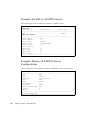
Example: Display FC Cards
152
Example: Display FC Card Utilization
Watch FC Card Utilization
Set FC Port Attributes
Syntax
153
153
154
Parameter Description
154
Example: Set the Link Down Time-Out
▼
152
156
Configure a Port for Direct-Attached Storage
Removing vHBAs
157
158
General Procedure
158
Environments Where the General Procedure Applies
Environments Where Special Procedure is Required
158
159
Procedures for vHBA Delete in Special Environments
Syntax
160
Remove vHBAs Connected to VMware Virtual Machines
▼
159
160
Removing vHBAs Connected to Virtual Machines Using VMFS
Remove vHBAs Connected to Servers Using Direct Disk Access
161
▼
Removing vHBAs Connected to Linux Servers
▼
Removing vHBAs Connected to Windows Servers Hosted in
VMware 162
Removing vHBAs in a Linux Multipath Environment
160
161
163
▼
Removing a vHBA and Rebooting the Server
▼
Removing a vHBA While Maintaining Service
▼
Removing a vHBA Without Reloading vHBA Drivers
163
164
165
Contents
xi
vHBA Statistics
167
Fibre Channel Monitoring
Syntax
168
Example
168
LUN Masking
Syntax
168
169
171
Parameter Description
▼
Set a LUN Mask
171
172
Optional LUN Masking: No Report LUN Interception
Syntax
175
Example
▼
9.
175
Change Port Topology from Fabric to Loop
VMware ESX Servers
176
179
Introducing Virtual I/O for VMware ESX
VMware ESX Support in XgOS
Syntax
174
179
180
181
ESX Utilities
181
ESX Configuration
182
▼
Enable vNIC Communication Between the ESX Server and the Oracle
Fabric Interconnect 182
▼
Monitor vNICs
Caveats
187
188
Set Local ID for Resources on Down or Unattached Server Profiles
NIC Teaming and Load Balancing
Automatic Rescans in ESX
188
189
Potential Issues With Automatic Rescans
10.
Network QoS for vNICs
QoS Terminology
xii
191
XgOS User’s Guide • September 2014
191
189
188
Bandwidth
Burst Size
192
192
Network QoS Services
193
QoS Operations Overview
QoS Feature Matrix
QoS Default Sets
Syntax
195
195
197
Example
197
QoS Custom Sets
Syntax
193
197
198
Automatic Calculation
199
Example: vNIC Custom Policer for a 10GbE Card
▼
Create a Policer for vNIC
200
ACLs With QoS and Application QoS
202
Example: ACL-Based Policer for 10GbE I/O Cards
▼
Create ACL-Based Policer
Disabling QoS on a vNIC
Syntax
199
203
203
205
205
Examples
205
Application QoS With Ingress 802.1p and IP Precedence Mapping
DSCP Mapping on 10GbE Cards
11.
SAN QoS for vHBAs
SAN QoS Features
Commands
Syntax
207
209
209
210
210
Parameter Description
▼
206
210
Create vHBA With Shaping
211
Contents
xiii
12.
Access Control Lists
Setting Actions
Syntax
213
214
214
Parameter Description
Example
216
Setting Conditions
Syntax
215
216
216
Operators
217
Support
217
Example
218
Displaying ACLs and Rules
Syntax
218
Parameter Description
Examples
218
219
Removing ACLs
Syntax
219
220
Parameter Description
Example
218
220
220
Example: Denying Egress Traffic
▼
13.
Deny Egress Traffic
221
Link Aggregation Groups (LAGs)
Employing LAG
220
225
225
Link Aggregation Control Protocol (LACP)
Port Assignment in the LAG
LAG Considerations
LAG Numbering
LAG Commands
Syntax
xiv
228
229
XgOS User’s Guide • September 2014
228
227
226
226
Parameter Description
229
LAG Configuration Options
230
Example LAG Configuration for Peer Device
Configuring a Static LAG
▼
231
232
Configure a Static LAG
232
Configuring a Passive Mode LAG
233
▼
Configure a LAG for “Passive” Mode (Dynamic LAG)
▼
Configure Individual Ports for Passive Mode LACP
Deleting a LAG
Delete All LAGs from a 10-Port GE Module
Delete a Port from a LAG
237
237
Delete an Ethernet Port from a Passive Mode LAG
239
Xsigo Directory Service
240
XDS Registration Process
Add Server Profiles
OpenSM Decoupling
Syntax
Example
241
242
244
244
Parameter Description
244
245
User Authorization and Access Control
Configuring IMS
Syntax
237
239
Virtual I/O Fabric
15.
236
236
Delete a Single LAG from a 10-Port GE Module
Clusters
235
236
Delete All LAGs from an Oracle Fabric Interconnect
14.
234
247
248
249
Parameter Description
249
Contents
xv
Using the Internal IMS
User Roles
▼
250
250
Create a User Account
251
How Access is Controlled By User Roles
▼
Grant Privileges to a Local User Account
Using Active Directory as the IMS
Syntax
▼
252
253
254
254
Configure AD Users and Roles
255
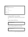
Example: Active Directory Server With Default Authentication
Example: Configure Kerberos as a Secondary AD Server
Example: Set IMS to an AD Server
256
257
258
Example: Display All AD Server Configuration
Using Role Group Mappings for AD/LDAP Users
259
259
Interaction Between Existing Groups and Role Group Mappings
Interaction Between Different Role Group Mappings
Syntax
261
262
Parameter Description
262
Example: Configure Role Group Mapping
▼
Configure a Role Group Mapping
262
263
Example: Add Role Group Mapping With a Regular Expression
▼
Add a Role Group Mapping
264
Example: Remove a Role Group Mapping
Using RADIUS as the IMS
Syntax
264
265
265
Example: RADIUS IMS Server With Default Authentication
Example: RADIUS IMS Server With CHAP Authentication
Configure RADIUS Users and Roles
Example: Adding a RADIUS User
xvi
261
XgOS User’s Guide • September 2014
267
267
266
266
264
Example: Changing a RADIUS User’s Privileges
Example: Set IMS to a RADIUS Server
268
Example: Display all RADIUS Server Configurations
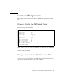
Common IMS Operations
269
Example: Control Cached Authentication Data
Setting the Shell Inactivity Timeout for Root User
16.
Set Shell Inactivity Timeout
Monitoring XgOS
SNMP
268
269
Example: Display the IMS Search Order
▼
267
269
270
270
273
273
Syntax
274
Example: SNMP Configuration
Configure Trap Destinations
MIB Support
IF-MIB
274
274
275
275
XSIGO-IODIRECTOR-ENTITY-MIB
Monitoring With Xsigo’s SNMP MIBs
Hardware Monitoring
Chassis Status
277
277
Physical I/O Port Status
278
280
Temperature Sensors
281
Power Supply (PSU) Status
System Status
276
277
I/O Module Status
Fan Status
276
285
286
Basic System Information
286
System Controller (SCP) Status
Virtual I/O Interfaces
287
287
Contents
xvii
Listing Virtual Interfaces
Virtual Interface Status
Traffic Counters
287
288
288
Input and Output Traffic Counters
Server Profile Status
Alarms
288
289
290
Syntax
Example
290
290
Xsigo ProWatch Overview
ProWatch Modes
291
291
ProWatch Transmission Schedules
HTTP Proxy Support
291
292
ProWatch Command Syntax
293
ProWatch Parameter Descriptions
Optional Qualifiers
293
295
Internet Connection Requirement
295
Sending ProWatch Data When Alarms Occur
Configuring ProWatch
▼
▼
296
Configure ProWatch
Snoozing ProWatch
297
300
Configure Phone Home Snooze
300
Displaying XgOS System Configuration
301
Syntax
296
301
Parameter Description
302
Example: Monitor I/O Port Status
304
Example: Display Operating System Details
Example: Display the Log Level
Displaying System Statistics
xviii
XgOS User’s Guide • September 2014
307
306
305
Syntax
307
Example: Display vNIC Status
307
Tracing End-to-End IB Path Continuity
▼
17.
Determine the IB Path Continuity
System Management
Syntax
309
313
System Image Upgrades
313
314
Parameter Description
▼
308
Upgrade XgOS
Clear Configuration
314
315
317
Example: Clear All Configuration and Upgrade the System
System Configuration
Syntax
318
318
Example: Display the Configuration of a F1-15
Example: Display the Configuration of a F1-4
Example: Print the Configuration
System Control
Syntax
318
319
319
320
Example: Broadcast a Message
320
Examples: Initiate Immediate Cold Start
Network Time Protocol (NTP) Server
321
322
322
Parameters
322
Login Methods
322
Console Login
SSH Login
▼
318
319
Parameter Description
Syntax
317
322
323
Change root Password
324
Contents
xix
▼
Disable or Enable Root Login Over SSH
Display Login Information
Syntax
324
325
Example
325
Setting System Password Strength
Syntax
325
327
Parameters
Example
324
327
327
Setting the Oracle Fabric Interconnect Management IP Address
▼
Set or Change the Management Address of the Oracle Fabric
Interconnect 328
Restoring Factory Defaults
331
Effects on the Oracle Fabric Interconnect
Power Down and Power Up
Syntax
Example
Syntax
Example
331
332
332
332
Software Information
332
332
333
Getting System Log Files
334
Parameter Description
335
Example: Redirect show tech-support
335
Example: Gather All Files With get log-files -all
Upgrading Host HCA Option ROM and Firmware
Considerations
336
337
338
Get the Latest Option ROM and Firmware
339
Install Option ROM and Firmware and Pushing it to Hosts
Command Syntax
340
Parameter Description
xx
328
XgOS User’s Guide • September 2014
341
340
Resetting the HCA
341
Displaying All Option ROM Images on the Oracle Fabric Interconnect
Displaying All Firmware Images on the Oracle Fabric Interconnect
Removing the Option ROM
Removing the Firmware
344
Applying System Patches
Command Syntax
347
347
348
Parameter Description
▼
Apply a Patch
▼
Remove a Patch
348
348
349
Scripting XgOS Commands
351
Scripts That Mimic UNIX Commands
Aikido Scripting Language
351
352
Example: Create 10 vNICs Using Aikido
Example: Move and Rename Files
SEDIT Script Editor
Syntax
344
347
Review Patch File Contents
18.
344
Upgrade the Option ROM and Firmware Images
Obtain Patch Files
352
353
354
354
Example: Redirect CLI Output to a File and Editing the File
▼
19.
Create Your Own Commands
354
355
Source RPM: Building OVN Host Drivers
Overview
343
343
Upgrading the Option ROM and Firmware Images
▼
342
357
358
Compatibility
Prerequisites
358
358
Contents
xxi
SRC RPM File
359
Basic rpmbuild Example
The SPEC File
359
360
Environment Variables
362
Build Option 1: Stock Kernels
362
Build Option 2: Custom Kernels
363
Build Option 3: Kernel With Upgraded OFED Stack
364
Build Option 4: Combination of Customer Kernel and Upgraded OFED Stack
365
Non-RPM Builds
365
OFED Patch Files
366
RDMA Headers
▼
367
Add RDMA Headers
InfiniBand Headers
367
367
Required Information for Contacting Customer Support
20.
Upgrading XgOS
369
XgOS Upgrade Overview
369
Understanding XgOS Upgrade
369
Saving and Restoring Your Configuration
Selecting an Upgrade Procedure
Basic OS Upgrade
368
370
371
371
Basic Upgrade Process
372
▼
Upgrade OS on the Oracle Fabric Interconnect
▼
Upgrade Linux Host Servers That Boot Locally
373
Upgrading Linux Hosts In a SAN Boot Environment
Upgrading VMware Host Servers
379
Compatible Software Versions
379
▼
xxii
Upgrade VMware Host Servers
XgOS User’s Guide • September 2014
380
376
379
Upgrading Windows Host Servers
381
▼
Upgrading Windows Host Servers
▼
Upgrading Windows HCA Firmware and Option ROM
Xsigo Dependency Service
381
382
384
Setting the Dependency of Other Services Upon XgDependRoot
Removing Dependencies Manually
385
Removing Xsigo Drivers and Any Dependencies
High Availability System Upgrade
385
385
High-Availability Upgrade Process
Compatible Software Versions
385
387
▼
Upgrade First ESX Sever and Fabric Interconnect
▼
Upgrade Second ESX Server and Fabric Interconnect
Glossary
Index
384
387
392
395
403
Contents
xxiii
xxiv
XgOS User’s Guide • September 2014
Using This Documentation
This document provides information about the XgOS CLI and on upgrading XgOS
for the Oracle Fabric Interconnect.
■
“Related Documentation” on page xxv
■
“Feedback” on page xxv
■
“Support and Accessibility” on page xxvi
Related Documentation
Documentation
Link
All Oracle products
http://www.oracle.com/documentation
Oracle Virtual Networking http://www.oracle.com/goto/FABRIC-INTERCONNECT/docs
Documentation
Feedback
Provide feedback about this documentation at:
http://www.oracle.com/goto/docfeedback
xxv
Support and Accessibility
Oracle customers have access to electronic support through My Oracle Support. For
information visit http://www.oracle.com/pls/topic/lookup?ctx=acc&id=
info or visit http://www.oracle.com/pls/topic/lookup?ctx=acc&id=trs
if you are hearing impaired.
xxvi
XgOS User’s Guide • September 2014
CHAPTER
1
XgOS CLI Overview
The XgOS command-line interface (CLI) includes commands to configure every
aspect of the Oracle Fabric Interconnects F1-15 and F1-4. This chapter introduces the
XgOS CLI and the categories of objects it configures. It contains the following major
sections:
■
“Command Syntax Conventions” on page 2
■
“Entering Commands and Getting Help” on page 2
■
“Logging in to the Oracle Fabric Interconnect” on page 9
■
“Virtual Resources Quick Start” on page 9
For more detailed information about these topics, see the following:
■
Specifying chassis hardware elements, see “Configuring Hardware Elements” on
page 17.
■
Understanding the XgOS file system, see “XgOS File System Access and Logging”
on page 45.
■
Scripting repetitive tasks, see “Scripting XgOS Commands” on page 351.
■
Configuring the CLI, see “Configuring the XgOS CLI” on page 53.
1
Command Syntax Conventions
Convention
Description
courier bold
Commands and keywords that must be
show vnic
entered exactly as shown. It also highlights
significant lines in the screen output display.
courier plain Actual display output that has been copied
Examples
resourceUnavailable
from the device. Also used for variable
names shown in command syntax.
“ ”
Quotes reference specific fields taken from
the screen display on the device.
See the “state” field.
< >
Angle brackets indicate variables for user
input. Replace the angle brackets and
variable name with information that is
indicative of your setup.
add vnic
<vnic-name>.<server-profile>
<slot>/<port>
{}
Curly braces indicate a choice of required
keywords or variables. You must enter at
least one of the enclosed parameters.
set vnic {*|<vnic-name>}
[ ]
Square brackets indicate a choice of optional show system version [-all]
keywords or variables.
|
A pipe operator indicates a choice. You can
enter one of the parameters on either side of
the pipe.
set vnic {*|<vnic-name>}
Entering Commands and Getting Help
The command-line interface (CLI) enables you to access the following elements:
2
■
Virtual Resources—The virtual NICs, virtual HBAs, and other items involved in
providing virtual I/O for your systems. For an introduction to configuring virtual
I/O, see “Virtual Resources Quick Start” on page 9.
■
File System—A file storage system. See “XgOS File System Access and Logging”
on page 45.
■
Hardware—Servers, I/O cards, and system logs. For the details about referring to
these on the command line, see “Configuring Hardware Elements” on page 17.
XgOS User’s Guide • September 2014
■
Scripting Engine—Enables you to run scripts within the CLI for each I/O card.
The engine also enables you to define new commands. Script support in the XgOS
CLI includes a full text editor for writing and revising your scripts. For the details
about the scripting engine, see “Scripting XgOS Commands” on page 351
This section introduces the CLI itself and explains the online help that is available.
Command Completion
The CLI includes a powerful command-completion feature that informs you of
possible commands, subcommands, and options at each point on the command line.
The following kinds of command completion are available:
■
To complete an unambiguous entry, press the Tab key.
■
If your entry is unambiguous, the CLI completes the command or subcommand
that you have begun typing. For example, if you enter the following:
add server-[Tab]
the CLI adds profile to your command line as the only legitimate completion.
This form of command completion can potentially save you a lot of typing.
■
To see valid completions at any point, type ? on the command line.
■
Typing a question mark causes the CLI to print a list of valid completions, and
some short help text for each item, for what is currently on the command line. For
example, if you enter the following:
ad?
The CLI responds with the following:
Possible completions:
[Configuration commands]
add
Add a configuration object to the system if it doesn’t already exist.
[Scripts]
add10vnics
■
You can also press the Tab key twice to get this same command completion.
The command-completion facility is context sensitive and always displays what the
CLI determines to be valid at the point in the command where you request the
completion. You can configure the CLI to automatically complete the command
whenever the space bar is pressed. (Refer to the set cli space-completion
command.)
Chapter 1
XgOS CLI Overview
3
For example, to get command-completion hints and context-sensitive help about
adding a vNIC:
add vnic ?
Possible completions:
<name> Virtual NIC name
Repeat '?' for detailed help.
Online Help
In addition to command completion, the CLI includes online help topics at various
levels. To access these topics enter help <command>. The CLI displays the detailed
help topic for that item, if such a topic is available.
Certain higher-level concepts also have help topics within the CLI. Enter help
<TopicName> to see these help items. Topics in the CLI online help include:
■
Getting-started: Information about getting started with the system
■
Scripts: Information about the use of scripts
■
Concepts: High-level concepts describing the OVN system
■
High Availability: High availability features
■
VLANS: Virtual LAN features
■
QoS: Quality of Service features
■
Aikido: Information on the Aikido programming language used by the CLI for
scripting facilities
■
Roles: Xsigo's Role Based Access Control mechanism
■
Phone-Home: the command for Xsigo ProWatch facility for remote diagnostics
For example, to view the help topic about adding vNICs:
help add vnic
Add a new virtual Network Interface Card (vNIC) to the system. You must provide
a hierarchical name for the vNIC at the time that it is added. A 'hierarchical'
name includes the name of the vNIC, plus the name of the server profile to which
the vNIC is assigned. The two names are separated by the dot '.' character. For
example: 'add vnic <vNIC_name>.<server_profile_name>'.
A second (optional) parameter of the 'add' command specifies the termination for
the vNIC. A vNIC can be terminated on an I/O port. For example:
‘add vnic <vNIC_name>.<server_profile_name> slot/port'.
4
XgOS User’s Guide • September 2014
Editing Commands on the Command Line
While entering a command, you can move around in the command-line text and edit
it. The following list shows the control key strokes that are available:
■
Left and right arrow keys: Move the cursor to either the left or to the right on the
command line.
■
Up and down arrow keys: Scroll up and down in the command history.
■
Ctrl-L: Retype the line
■
Ctrl-U: Erase the line
■
Ctrl-C: Quit the command
■
Ctrl-R: Search the command history.
■
Ctrl-E: Move to the end of the command
■
Ctrl-A: Move to the beginning of the command
Command History
The CLI maintains a history of the commands that you have entered, over multiple
sessions. Use the up and down arrows to scroll through the command history and
find a specific command. When you find the desired command, press the carriage
return on the keyboard to execute that command.
You can also search the command history for a sequence of characters using Ctrl-R.
As you type characters after Ctrl-R, the CLI searches backwards through the
command history for commands containing those characters. To select a command
found this way, press the carriage return. Alternatively, use Ctrl-R again to continue
the search.
Redirecting Output
You can redirect the output from any command may be redirected to a file by
placing a '>' sign followed by a filename, at the end of the command. For example,
entering the following will run the command, and place the output in a file called
allvnics in the current directory:
show vnics > allvnics
Another way to redirect the command output is to execute the command inside
backtick characters and then place the result in a variable. For example, if you enter:
var vnics = ‘show -list vnics’
Chapter 1
XgOS CLI Overview
5
The variable vnics contains a vector of lines containing the output from the show
-list vnics command.
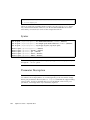
Wildcards
You can use wildcards to control the display of output. Wildcards may be used in
most of the XgOS show commands to select a set of objects. The only wildcard
character supported is the asterisk (*) which causes zero or more of any character to
be displayed in the show command. Wildcards can also represent entire names.
Strings you create with wildcards are case sensitive, so make sure you enter the
wilcarded item correctly. For example, vNICs named “vnic1” and “vnic2” are not
displayed if you issue show vnic V*. If you issue show vnic v* the vNICs are
displayed.
Note – Not all show commands support the use of wildcards (for example, LAGs
and VLANs do not support them for selecting the LAG name or VLAN number)
For example, if you enter:
show vnic v*
The wildcard character represents zero or more characters in a name string starting
with “v.” The result of this command is a list of all vNIC with “v” as the first letter.
If you enter:
show vhba *.*test*
The first wildcard represents an entire name, and the second and third represent
individual characters. The result of this command is a list of all vHBAs on all Server
Profiles that contains the string “test” in their name.
If you enter:
show qos network policer */100m*
The first wildcard represents a name string for a Network QoS policer, and the
second wildcard represents and characters in the policer rate. The result of this
command is a list of all Network QoS policers in any set that limit the CIR to 100
Mbps.
6
XgOS User’s Guide • September 2014
Pipes
You can use pipes to control the display of output in the CLI. Pipes in the XgOS CLI
are like standard UNIX pipes, and they use the same syntax. For example, if you
enter:
show vnic * | grep down
The resulting output displays all vNICs in the down state. XgOS pipes work with
any command, but is used with most effectiveness when coupled with the grep
command. XgOS pipes are not limited to only one set of pipes; many stages in the
pipeline are supported.
Filters
The CLI supports command filters, which are boolean expressions that operate on
columns of object output. You can use filters to specify objects that will be displayed
in the output of the following show commands:
■
show vnic
■
show vhba
■
show server-profile
■
show physical-server
To specify a filter for these commands, append a “where” clause containing
operands and operators. Some examples are provided later in this section.
Filters determine specific output (the table columns) that will be displayed when
you issue one of the listed commands. The value of a table column in a show
command can be compared to a constant using one of the operators in the following
table.
Operator
Means
=
equal to
<>
not equal to
<
less than
<=
less than or equal to
>
greater than
>=
greater than or equal to
like
regular expression match
Chapter 1
XgOS CLI Overview
7
Expressions can be combined using “and”, “or”, and “xor”. Expressions can also be
enclosed in parentheses.
For example, if you enter:
show vnic * where if = 1/1
This command shows all vNICs terminated on interface 1/1.
If you enter:
show vhba priv*.prod where if-state <> up
This command shows vHBAs with a name that starts with “priv” and are on the
“prod” server profile, filtering those with an if-state column (interface state) that is
not “up”
If you enter:
show server-profile * where connection like "extsw" and state = up
This command shows all server-profiles that are connected to an external switch and
are “up”
If you enter:
show server-profile * where vnics > 0 or vhbas > 0
This command shows all server profiles that have a vNIC or vHBA on them.
Naming Conventions
Names for objects in the OVN information model should follow these naming
guidelines. Here is a partial list of characters that should be avoided when naming
server profiles, vNICs, and vHBAs:
■
$ which is used by the CLI for textual replacement of expressions.
■
/ (slash) and ^ (caret) and % (percent sign) cause errors and prevent the named
item from being displayed.
■
: (colon) causes a permissions error.
Internal blank spaces are accepted when they are enclosed in quotation marks. For
example, a server profile named “web apps” is valid, but web apps is not.
While the XgOS CLI and Oracle Fabric Manager do not enforce rules about naming
objects, we recommend the following guidelines:
8
XgOS User’s Guide • September 2014
■
Characters accepted in the names of vNICs and vHBAs include alphanumerics
and underscore (_). Avoid using other characters.
■
Characters accepted in the other objects (for example, server profiles, LUN Masks,
QoS Profiles, ACLs, and so on) include alphanumerics, dash (-), and underscore
(_). Avoid using other characters.
Logging in to the Oracle Fabric
Interconnect
You can use the command-line interface through the console or by using a secure
shell (SSH). For details about different login methods, see “Login Methods” on
page 322.
Generally, you will log in using a secure shell and your own account or the default
account. To use the default account, enter the user name admin and the password
admin.
Virtual Resources Quick Start
This section provides a brief introduction to the commands used to configure and
monitor virtual resources on the system.
Basic Commands
There are several fundamental commands that influence the configuration database
and perform basic system functions:
add
Create and delete virtual resources
remove
Delete virtual resources
set
Modify properties of virtual resources
show
Display properties of virtual resources
system
Perform chassis-related functions:
Chapter 1
XgOS CLI Overview
9
Server Profile Commands
Server profiles are containers that hold vNICs/vHBAs and are assigned to physical
servers. Profiles provide the flexibility to move an I/O personality from one physical
server to another.
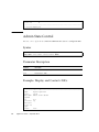
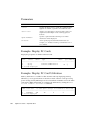
Server Profile Examples
■
Create a server profile for xserver1 and assign it to the physical server
add server-profile xserver1 xserver1@iowa:ServerPort7
■
Display the properties of all server profiles:
show server-profile
■
Delete the server profile:
remove server-profile xserver1
■
Disconnect a server profile from a physical server:
set server-profile xserver1 disconnect
Note – This command will cause a service disruption, as a result, a confirmation
prompt is displayed to verify the disconnect.
Assign an existing server profile to a server:
set server-profile xserver1 connect xserver1@iowa:ServerPort7
See “Server Profiles and Gateways” on page 69 for more information.
vNIC Commands
vNICs are given a name and assigned to a server profile and an Ethernet module
port.
10
XgOS User’s Guide • September 2014
vNIC Command Examples
■
Create a new vNIC for xserver1 and assign it to port 2 on the Ethernet module in
slot 8:
add vnic vnic0.xserver1 8/2
■
Give vnic0 on xserver1 the IP address of 11.0.0.1 with netmask 255.255.255.0:
set vnic vnic0.xserver1 -addr-type=static -ip-addr=11.0.0.1/24
■
Display the properties of all vNICs:
show vnic
■
Change the netmask on vnic0.xserver1 to 255.0.0.0:
set vnic vnic0.xserver1 –netmask=255.0.0.0
■
Set vnic0.xserver1 to DHCP:
set vnic vnic0.xserver1 –addr-type=dhcp
■
Change the termination port of a vNIC:
set vnic vnic0.xserver1 –if=8/4
■
Create an HA vNIC with primary port 8/1 and secondary port 8/2:
add vnic vnic0.xserver1 8/1 ha 8/2
■
Delete a vNIC:
remove vnic vnic0.xserver1
See “Virtual Network Interface Cards (vNICs)” on page 77 for more information.
vHBA Commands
vHBAs are given a name and assigned to a server profile and a Fibre Channel (FC)
module port.
Chapter 1
XgOS CLI Overview
11
vHBA Command Examples
■
Create a new vHBA for xserver1 and assign it to port 1 on the FC module in slot
15:
add vhba vhba0.xserver1 15/1
■
Display the targets and LUN IDs the vHBA can detect:
show vhba vhba0.xserver1 targets
■
Display the properties of all vHBAs (WWNN/WWPN):
show vhba
■
Request a vHBA to rescan the SAN fabric:
set vhba vhba0.xserver1 rescan
Note – You would do this if you changed LUN masking on an array, for example.
vHBA prescan commands allow an “unbound” vHBA to perform an NPIV login and
“see” the available targets and LUNs. You can only perform these commands on a
vHBA and server-profile that is not assigned to a physical server. You can check this
by typing show server-profile and make sure the state is “up/unassigned”.
vHBA Prescan Examples
■
Create a server profile and vHBA to scan the fabric:
add server-profile testserver
add vhba vhba0.testserver 15/1
show vhba vhba0.testserver (view WWPN to provision LUNs)
■
Request an unbound vHBA to perform an NPIV login:
set vhba vhba0.testserver prescan
■
If you change LUN masking or if the fabric changes without an RSCN, you must
logout/login to “rescan”:
set vhba vhba0.testserver remove-prescan
set vhba vhba0.testserver prescan
12
XgOS User’s Guide • September 2014
■
Request an unbound vHBA to logout of the SAN fabric:
set vhba vhba0.testserver remove-prescan
■
Display vHBA targets:
show vhba vhba2.testserver targets
See “Virtual Host Bus Adapters (vHBAs)” on page 133 for more information.
I/O Card Commands
The I/O modules and ports are the termination points of vNICs and enable vNICs to
access network resources.
I/O Card Examples
■
Display all I/O cards in the chassis and their status:
show iocard
■
Display the port status of all I/O ports in the chassis:
show ioport
■
Change the MTU of an I/O port to support jumbo frames:
set ethernet-port 8/4 –mtu=9194
Note – You can only change the MTU of a port when no vNICs are assigned
■
Display the properties of a specific I/O port:
show ioport 8/4
■
The show command shows all parameters for the specified I/O port.
Chapter 1
XgOS CLI Overview
13
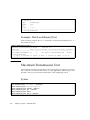
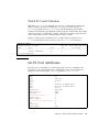
Miscellaneous Show Commands
■
Display the XgOS version:
show system version
■
Display the current system configuration:
show system info
■
Display management Ethernet info:
show system interfaces
■
Display all logged in users:
show login
■
Display environmental information:
show hardware
■
Display information for supporting an issue:
get log-files -all
■
Display discovered physical servers:
show physical-server
Virtual Resource Naming Restrictions
As with all computer systems, the names you can set on virtual I/O resources can
contain a restricted character set. Names of vNICs and vHBAs can contain:
■
the letters A-Z and a-z
■
the numerals 0-9
■
the underscore character (_)
All other virtual I/O resources, such as server profiles and LUN masks, can contain:
14
■
the letters A-Z and a-z
■
the numerals 0-9
■
the underscore character (_)
XgOS User’s Guide • September 2014
■
dash (-)
The names of virtual resources are restricted to the following lengths:
■
vNICs: between 2 and 10 characters
■
vHBAs: between 2 and 15 characters
■
server profiles: between 1 and 31 characters
Chapter 1
XgOS CLI Overview
15
16
XgOS User’s Guide • September 2014
CHAPTER
2
Configuring Hardware Elements
When configuring virtual I/O, you must refer to the various hardware elements of
the Oracle Fabric Interconnect. This chapter presents detailed information about
those elements and how to refer to those elements on the command line.
■
“Slot/Port Numbering Scheme” on page 17
■
“InfiniBand Ports” on page 19
■
“I/O Modules” on page 23
■
“I/O Ports” on page 29
■
“Determining HCA Ports and Checking Firmware Version in Servers” on page 31
■
“Hardware Status and Environmentals” on page 32
■
“Interfaces and Interface State” on page 44
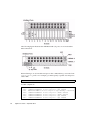
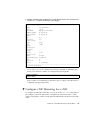
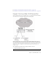
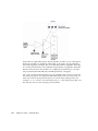
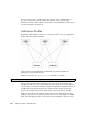
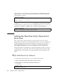
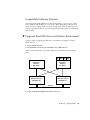
Slot/Port Numbering Scheme
The following figure illustrates the InfiniBand and I/O ports on the Oracle Fabric
Interconnect F1-15.
17
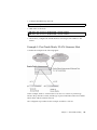
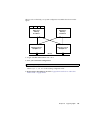
The following figure illustrates the InfiniBand and I/O ports on an Oracle Fabric
Interconnect F1-4.
When referring to an I/O module and port on the command line, you use the form
I/O_Slot/Port_Number. For example, you must specify a specific slot and port to
add a vNIC:
add vnic foo.bar ?
Possible completions:
14/1
14/2
14/3
14/4
14/5
14/6
14/7
18
nwEthernet1GbPort in slot 14 port
nwEthernet1GbPort in slot 14 port
nwEthernet1GbPort in slot 14 port 3
nwEthernet1GbPort in slot 14 port
nwEthernet1GbPort in slot 14 port
nwEthernet1GbPort in slot 14 port
nwEthernet1GbPort in slot 14 port
XgOS User’s Guide • September 2014
1 (up) unused
2 (up) unused
(up) used by 7 resources
4 (down) unused
5 (down) unused
6 (up) unused
7 (up) unused
14/8 nwEthernet1GbPort in slot 14 port 8 (up) used by 8 resources
14/9
nwEthernet1GbPort in slot 14 port 9 (down) unused
14/10 nwEthernet1GbPort in slot 14 port 10 (down) unused
add vnic foo.bar 14/1
In command output, the module and slot consists of the following information
elements:
■
connection type, for example either network (nwEthernet) or fibre channel SAN
(sanFC)
■
port type, for example either Ethernet or Fibre Channel.
■
rate, for example 1 gigabit per second (1Gb), 10 Gigabits per second (10Gb)
■
slot or port, for example port or module.
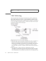
InfiniBand Ports
InfiniBand (IB) is a channel based, switched-fabric interconnect for servers. IB
interconnects processor nodes and I/O nodes to a system area network. The
architecture is independent of the host operating system and processor platform.
The Oracle Fabric Interconnect contains several internal 24-port IB switches
(Mellanox). One switch attaches to an internal HCA (IOCPort16). Each external IB
port connects to a external HCA installed on a remote host server. You can connect
an external InfiniBand switch to the Oracle Fabric Interconnect to extend the number
of IB ports.
Chapter 2
Configuring Hardware Elements
19
The Oracle Fabric Interconnect contains an embedded Subnet Manager (SM) that
manages the switching and pathing tables within the IB fabric. When there are
multiple SMs on a subnet, one SM will be the master SM through an election
algorithm. The remaining SMs become standby SMs. There is only one master SM
per subnet.
The master SM is a key element in initializing and configuring an IB subnet. The
master SM is elected as part of the initialization process for the subnet and is
responsible for the following:
■
Discovering the physical topology of the subnet
■
Assigning Local Identifiers (LIDs) to the end nodes, switches, and routers
■
Establishing possible paths among the end nodes
■
Sweeping the subnet, discovering topology changes and managing changes as
nodes are added and deleted.
The communication between the master SM and the SM agents, and among the SMs,
is performed with subnet management packets.
Note – If you prefer to use a 3rd-party SM (not the Oracle Fabric Interconnect), see
“OpenSM Decoupling” on page 244 for information on how to disable the SM.
Note – The IB specification is posted at
http://www.infinibandta.org/specs/register/publicspec/.
Syntax
Use the following CLI commands to display and manage InfiniBand port
information:
show fabric-port
show physical-server [<name>][*]
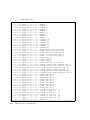
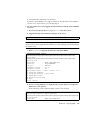
Example: Display the Fabric Ports
show fabric-port
----------------------------------------------------------------name
chocolate
type
hcaPort
descr
20
XgOS User’s Guide • September 2014
chassis-port ServerPort19
id
2c90200204929
state
N/A/up
m-key
0
lid
4
sm-lid
61
link-width
4x
link-speed
2_5_Gbps
----------------------------------------------------------------...
----------------------------------------------------------------name
south-dakota
type
hcaPort
descr
chassis-port IOCPort16
id
1397020100013d
state
N/A/up
m-key
0
lid
61
sm-lid
61
link-width
4x
link-speed
2_5_Gbps
----------------------------------------------------------------36 records displayed
Field
Description
name
Displayed host name of the server.
type
Type of port.
name
Port GUID name.
descr
User defined port description.
chassis-port
Local IB chassis port used for the connection.
The Oracle Fabric Interconnect itself has an internal HCA on the SCP
used to communicate with the IB fabric. This internal HCA switch port is
IOCPort16. This port is the Oracle Fabric Interconnect’s representation
in the IB framework.
id
Globally Unique Identifier (GUID). A persistent number that uniquely
identifies a device or component. An HCA is assigned a node GUID that
is stored in flash memory. Each port on an HCA is assigned a port GUID.
Xsigo’s IB vendor ID is 1397.
state
The administrative state of the local IB port on the chassis and the
operational state of that port, in the form
admin_state/operational_state.
Chapter 2
Configuring Hardware Elements
21
Field
Description
m-key
Management key. A construct that is contained in InfiniBand Architecture
(IBA) management datagrams to authenticate the sender to the receiver.
lid
Local Identifier. An address assigned to a port by the IB Subnet Manager
(SM), unique within the subnet, used for forwarding packets within the
subnet. The SM manages the switching and routing tables with the IB
fabric. The Source and Destination LIDs are present in the Local Route
Header. A Local Identifier is formed by the sum of the Base LID and the
value of the Path Bits. Unlike a fixed GUID, a LID can change from timeto-time.
sm-lid
The LID where the master SM is located. It is not the SM priority value.
link-width
link-speed
Link-width is the number of physical lanes (1, 4, 8, or 12) whereas link
speed is the speed of the physical lanes, such as 2.5 Gbps (SDR), 5 Gbps
(DDR), or 10 Gbps (QDR). If the link-width field is not 4x, there is
something wrong.
The InfiniBand Architecture (IBA) defines a number of different link bit
rates. The lowest bit rate of 2.5 Gbps is referred to as a 1x (times one)
link. Other link rates are 10 Gbps (4x) and 30 Gbps (1x2).
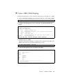
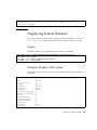
Example: Display the Physical Servers Connected
to the Chassis
The OVN host drivers communicate with Xsigo’s OpenSM by default. When an IB
connected host server boots up, the installed OVN host driver advertises the server’s
host name to the Oracle Fabric Interconnect.
Issue show physical-server command to display the list of InfiniBandconnected servers:
show physical-server
name
guid
descr port
cap server-profile
----------------------------------------------------------------alexander 2c90200204935
iowa:ServerPort8
ef-x spLinux
The alexander server is connected to the Oracle Fabric Interconnect named “iowa”
on IB port 8 (iowa:ServerPort8).
When you issue add server-profile <name>, you will see the reported host
server names for which command completion can configure:
add server-profile myprofile ?
Possible completions:
alexander@iowa:ServerPort19 Connection to host alexander (up)
22
XgOS User’s Guide • September 2014
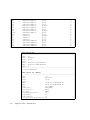
I/O Modules
Use show iocard command to display available I/O line card information in the
system.
There are feature differences and capability nuances between the 10-port Gigabit
Ethernet and 10 GE Gigabit Ethernet I/O hardware modules. For more details, see
“QoS Feature Matrix” on page 195, Chapter 12, and Chapter 7.
Syntax
show
show
show
show
show
show
show
show
show
show
show
show
show
show
show
iocard
iocard
iocard
iocard
iocard
iocard
iocard
iocard
iocard
iocard
iocard
iocard
iocard
iocard
iocard
*
{<slot>|<wildcard>}
{<slot>|<wildcard>}
{<slot>|<wildcard>}
{<slot>|<wildcard>}
{<slot>|<wildcard>}
{<slot>|<wildcard>}
{<slot>|<wildcard>}
{<slot>|<wildcard>}
{<slot>|<wildcard>}
{<slot>|<wildcard>}
{<slot>|<wildcard>}
{<slot>|<wildcard>}
{<slot>|<wildcard>}
acl-stats <rule-id>
alarms
dmesg
errors
ioport [*|<port>]
ioports
mac-table
qos
stats
vhbas
vnics
warnings
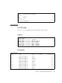
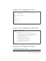
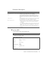
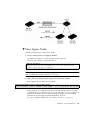
Example: Display I/O Modules in a F1-15
show iocard
slot
state
descr
type
v-resources
----------------------------------------------------------------3
up/up
sanFc2Port4GbLrCard
6
4
up/up
sanFc2Port4GbLrCard
0
5
up/up
nwEthernet4Port10GbCard
6
10
up/up
nwEthernet1Port10GbCard
0
4 records displayed
Chapter 2
Configuring Hardware Elements
23
The field “v-resources” indicates the number of Xsigo virtual resources (vNICs and
vHBAs,) that are associated with this card. vNICs can be bound only to network
Ethernet cards. vHBAs can be bound only to SAN FC cards. Because slot numbers
exceed 4 (for example, slot 10), the output displayed is for a F1-15.
Example: Display I/O Modules in a F1-4
show iocard
slot
state
descr
type
v-resources
----------------------------------------------------------------1
up/up
nwEthernet10Port1GbCard
9
2
up/up
nwEthernet10Port1GbCard
0
3
up/up
sanFc2Port4GbLrCard
9
4
up/up
sanFc2Port4GbLrCard
0
4 records displayed
The field “v-resources” indicates the number of Xsigo virtual resources (vNICs and
vHBAs,) that are associated with this card. vNICs can be bound only to network
Ethernet cards. vHBAs can be bound only to SAN FC cards.
Example: Display the MAC Table
show ethernet-card 2 mac-table
port
vlan
type
mac-address
----------------------------------------------------------------2/2
1
dynamic
00:0e:0c:4a:b8:f2
2/2
40
static
00:13:97:09:85:64
2/2
50
static
00:13:97:09:85:65
2/2
60
static
00:13:97:09:85:66
2/6
10
dynamic
00:0e:0c:4a:b8:f2
2/10
1
dynamic
00:0e:0c:4a:68:d5
2/10
1
dynamic
00:30:48:88:43:7c
2/10
1
dynamic
00:0d:bd:86:96:50
2/10
1
dynamic
00:11:85:a5:21:80
2/10
1
dynamic
00:11:85:a5:2a:7f
2/10
1
dynamic
00:11:85:a5:2a:40
2/10
1
dynamic
00:1d:a2:65:ff:01
2/10
1
dynamic
00:0f:20:e7:e3:01
2/10
1
dynamic
00:14:6c:c5:e2:c2
2/10
1
dynamic
00:13:97:03:50:79
2/10
1
dynamic
00:13:97:00:0f:28
2/10
1
dynamic
00:13:97:00:0f:2e
2/10
1
dynamic
00:13:97:00:00:25
24
XgOS User’s Guide • September 2014
2/10
1
2/10
1
2/10
1
2/10
1
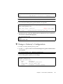
2/10
1
2/10
1
2/10
1
2/10
1
2/10
1
2/10
1
2/10
1
2/10
1
30 records displayed
dynamic
dynamic
dynamic
dynamic
dynamic
dynamic
dynamic
dynamic
dynamic
dynamic
dynamic
dynamic
00:13:97:01:a1:13
00:13:97:00:02:4f
00:13:97:00:00:13
00:13:97:80:00:03
00:13:97:00:00:16
00:13:97:80:00:0f
00:13:97:01:a0:c9
00:13:97:01:a0:ce
00:13:97:00:00:81
00:13:97:00:00:86
00:14:6c:81:41:36
00:03:f4:02:45:d4
The command shows information about a 10-Port GE module in slot 2 including the
VLAN number on the port, the type of MAC address and the MAC address(es)
associated with the port.
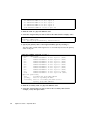
Controlling I/O Modules
The set iocard command can shut down, turn up, or reset I/O modules.
Syntax
set
set
set
set
set
set
iocard
iocard
iocard
iocard
iocard
iocard
{*|<slot#>}
{*|<slot#>}
{*|<slot#>}
{*|<slot#>}
{*|<slot#>}
{*|<slot#>}
clear-stats
down
reset
up
-descr=”<text>”
-type=<value>
These commands are supported on I/O modules only. The front panel, SCP, and
InfiniBand fabric board are not affected.
Chapter 2
Configuring Hardware Elements
25
Parameter Description
Parameter
Description
<slot#>|* down
Causes one or all I/O modules to be deactivated. When
the shutdown occurs, all power to the affected I/O
module is turned off. When you issue this command, a
warning message is displayed, and you are prompted for
confirmation before the module is shutdown. By default,
the module is not shut down. If you want the module
shutdown, you must explicitly answer yes (y) to the
prompt.
<slot#>|* up
Reactivates one, or all, of the I/O modules that are
inactive. Bringing a module up is the opposite of shutting
down a module. When the modules are started, all power
is turned on to the affected modules. By default, the
module is brought up without confirmation.
”<text>”
Specifies an optional description string. If the string will
contain multiple words that are separated by blank
spaces (for example, the Oracle Fabric Interconnect), you
must enclose the description string in double quotation
marks—for example, “Oracle Fabric Interconnect”
<value>
Sets the kind of I/O module that is in the slot. This option
is useful in cases where slots are pre-provisioned for an
I/O module before the I/O module is installed. The
following options are supported:
• nwEthernet10Port1GbCard for a 10-port 1 Gbps
Ethernet card
• nwEthernet1Port10GbCard for a 1-port 10 Gbps
Ethernet card
• nwEthernet4Port10GbCard for a 4-port 10 Gbps
Ethernet card
• sanFc2Port4GbLrCard for a Line Rate Fibre Channel
card
Caution – If you are pre-provisioning, when you actually install hardware modules,
make sure you get the right module type in the right slot. For example, if slot 13 is
pre-provisioned for a 10 GE module, make sure that a 10 GE module is installed in
slot 13. As an alternative, you can issue the set iocard <slot> -type command
to set change a module type for a slot before the module is inserted.
26
XgOS User’s Guide • September 2014
Example: Shut Down a Single I/O Module
To shut down a single I/O module:
set iocard 8 down
Shutting down IO cards will adversely affect any virtual IO
resource connected
to them and thus cut IO to the physical servers.
Are you sure you want to shutdown the IO card in slot 13 (y/n)?
Example: Bring Up an I/O Module
To bring up a single I/O module:
set iocard 8 up
Resetting I/O Modules
A module reset powers down one or all modules in the chassis, then powers them
back up.
Note – This command is supported on I/O modules only. The front panel, SCP, and
fabric board are not affected.
You can reset an I/O module by issuing the set iocard reset command. This
command has an option to reset all cards by using the asterisk wildcard character
(*), or a single card by specifying the number of the slot where the card is installed.
Here are some examples of resetting an I/O module. The following command resets
a single module in slot 8:
set iocard 8 reset
The following command resets all I/O modules in the chassis:
set iocard * reset
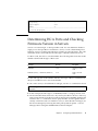
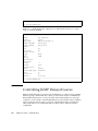
Installing and Monitoring 1-Port 10GbE I/O Modules
The 1-Port 10GbE I/O module can be installed in any slot on the chassis. It supports
the following features:
Chapter 2
Configuring Hardware Elements
27
■
128 vNICs per card
■
Card-level High Availability (HA)
■
Access Control List (flow) policing
■
QoS on the vNICs configured on the card
■
MTU sizes from 1500 bytes to 9194 Kbytes
■
IPv4 TCP/UDP checksum offload. If you want TCP Offload configured on the
vNIC, you must set this value at vNIC creation time. You cannot edit a configured
vNIC to add the Offload feature later.
■
Untagged VLANs. Each vNIC can be assigned to a single untagged VLAN
(between 1 - 4000)
■
8 traffic queues per vNIC
■
IGMP snooping. IGMP versions supported: v1, v2, v3 (partially supported)
■
Flow learning and statistics
■
512 multicast groups
■
802.1p, TOS, and DSCP mapping
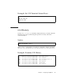
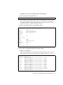
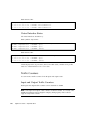
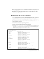
To monitor 1-Port 10GbE I/O modules, use show ioport to inspect the state and
configuration information on the ports.
The following example displays a port on a card installed in slot 8:
show ioport 1/1
-------------------------------------name
1/1
type
nwEthernet10Port1GbCard
state
up/up
descr
rate
auto/1 Gbps
mtu
1500
avail-in-cir
1 Gbps
avail-out-cir 1 Gbps
mode
access
flags
-s
vnics
2
vlans
none
-------------------------------------1 record displayed
The following example displays the card installed in slot 8:
show iocard 1
-------------------------------------slot
1
state
up/up
28
XgOS User’s Guide • September 2014
descr
type
nwEthernet10Port1GbCard
vnics
2
qos
default
acl
acl1
enables qas
----------------------------------------------------------------1 record displayed
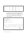
I/O Ports
Use show ioport to display I/O port information on an I/O port.
Syntax
show
show
show
show
show
show
show
show
ioport
ioport
ioport
ioport
ioport
ioport
ioport
ioport
*
<slot/port>
<slot/port>
<slot/port>
<slot/port>
<slot/port>
<slot/port>
[-detail]
alarms [-detail]
qos [-detail]
stats [-detail]
vhbas [-detail]
vnics [-detail]
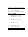
Examples
show ioport
name
type
state
descr
v-resources
-----------------------------------------------------------------------------1/1
nwEthernet1GbPort
up/up
2
1/2
nwEthernet1GbPort
up/up
0
1/3
nwEthernet1GbPort
up/down
0
1/4
nwEthernet1GbPort
up/down
0
1/5
nwEthernet1GbPort
up/up
0
1/6
nwEthernet1GbPort
up/up
0
1/7
nwEthernet1GbPort
up/up
0
1/8
nwEthernet1GbPort
up/down
0
1/9
nwEthernet1GbPort
up/down
0
1/10
nwEthernet1GbPort
up/up
0
2/1
nwEthernet1GbPort
up/up
6
Chapter 2
Configuring Hardware Elements
29
2/2
2/3
2/4
2/5
2/6
2/7
2/8
2/9
2/10
3/1
3/2
4/1
4/2
5/1
5/2
5/3
5/4
nwEthernet1GbPort
nwEthernet1GbPort
nwEthernet1GbPort
nwEthernet1GbPort
nwEthernet1GbPort
nwEthernet1GbPort
nwEthernet1GbPort
nwEthernet1GbPort
nwEthernet1GbPort
sanFcPort
sanFcPort
sanFcPort
sanFcPort
nwEthernet10GbPort
nwEthernet10GbPort
nwEthernet10GbPort
nwEthernet10GbPort
up/up
up/up
up/up
up/up
up/down
up/up
up/up
up/down
up/up
up/up
up/down
up/up
up/up
up/up
up/up
up/up
up/up
0
0
0
0
0
0
0
0
0
4
0
0
0
4
0
0
0
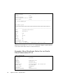
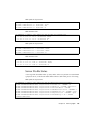
show ioport 3/1
----------------------------------------------------------------name
3/1
type
sanFcPort
state up/up
descr
wwnn
50:01:39:71:00:00:B0:1F
wwpn
50:01:39:70:00:00:B0:1F
vhbas 4
----------------------------------------------------------------1 record displayed
show ioport 3/1 -detail
----------------------------------------------------------------name
3/1
type
sanFcPort
state
up/up
descr
wwnn
50:01:39:71:00:00:B0:1F
wwpn
50:01:39:70:00:00:B0:1F
rate
auto/4Gbps
frame-size
2048/2048
exec-throttle
65535
int-delay
1000
fc-link-down-timeout
60
login-retry
8
login-timeout
4
fc-target-port-down-timeout 60
30
XgOS User’s Guide • September 2014
topo
F
loop-delay
5
tape-support
true
vhbas
4
----------------------------------------------------------------1 record displayed
Determining HCA Ports and Checking
Firmware Version in Servers
Servers can contain single- or dual-port HCA cards. You can determine whether a
single-port or dual-port HCA is installed in a server, as well as determining what
firmware version is loaded on the HCAs by searching for relevant strings. The value
returned from the search indicates the HCA type or the HCA firmware version.
For HCA cards, the value is a model number. The following table shows the model
number returned and the type of HCA card.
Card Type
Minimum Firmware
Revision
MT25204
1.2.0
Single port PCIe
card
MT25208 (Linux) / MT25218 (Windows)
5.1.4
Dual port PCIe
card
Description
For the card type, the model number indicates what type of HCA is installed. Each
dual-port card HCA has its own model number.
■
On a Linux server, to check the HCA card type, use the cat command as shown:
# cat /sys/class/infiniband/mthca0/hca_type
MT25204
■
In this example, the HCA type is an MT25204, which is a single port PCIe card.
■
The Oracle Fabric Interconnect uses only memory-free HCAs. Because of the way
Linux queries the HCA, the dual port HCA is displayed as MT25208 (mem-based)
whenever the cat command is used to query the HCA even though the HCA is
actually a mem-free card. On a Windows server, to check the HCA card type, use
the Device Manager by following the menu path System Properties -> Device
Manager, then locating the InfiniBand Host Channel Adapter.
Chapter 2
Configuring Hardware Elements
31
The Oracle Fabric Interconnect uses only memory-free HCAs. Because of the way
Windows queries the HCA for firmware information, Windows can determine
whether the HCA card is mem-based or mem-free. As a result, the dual port HCA is
correctly displayed as MT25218 whenever the Device Manager is used to query the
HCA. For the firmware version, the value is the current revision level.
■
To check the firmware version, use the cat command as shown:
# cat /sys/class/infiniband/mthca0/fw_ver
1.2.0
In this example, the MT25204 has firmware version 1.2.0 installed.
Hardware Status and Environmentals
Issue the show hardware command to display hardware information and
environmental statistics for the Oracle Fabric Interconnect. Various models of Oracle
Fabric Interconnect are supported for the Oracle Fabric Interconnect F1-4 and Oracle
Fabric Interconnect F1- 15, and there are some differences in the hardware
configuration of each. The main differences are:
■
The Oracle Fabric Interconnect F1-15 is a 4 rack-unit system with a maximum of
15 slots for I/O modules. The Oracle Fabric Interconnect F1-15 has an InfiniBand
fabric supporting SDR (10 Gbps), DDR (20 Gbps), or QDR (40 Gbps) connections
to host servers with InfiniBand HCAs.
■
The Oracle Fabric Interconnect F1-4 is a 2 rack-unit system which supports a
maximum of 4 I/O modules. The Oracle Fabric Interconnect F1-4 has an
InfiniBand fabric supporting SDR (10 Gbps), DDR (20 Gbps), or QDR (40 Gbps)
connections to host servers
■
The Oracle Fabric Interconnect Oracle Fabric Interconnect F1-15 power supplies
(PSUs) are on the rear of the chassis, and the Oracle Fabric Interconnect F1-4 PSUs
are on the front.
Additional commands are available to show the hardware status of the Oracle Fabric
Interconnects, such as show fabric-port, show config, and show system
info.
Syntax
show hardware
32
XgOS User’s Guide • September 2014
Example: Display Hardware Status for an Oracle
Fabric Interconnect F1-15
The show hardware command displays comprehensive output of all the important
hardware information for a Oracle Fabric Interconnect. This example is for a F1-15
with an SDR fabric.
show hardware
# Model: F1-15-CH-DDR
# Serial: 410510043
# Base MAC: 00:13:97:01:20:00
# Base WWN: 50:01:39:70:00:00:20:00
# Locator LED: off
#
# Date: Wed Jan 25 16:13:38 PST 2012
# User: admin
#
#
## IO Card Version status ########################################
slot type
model
part-num
serial
vchip-ver xt-ver
primary-boot-ver secondary-boot-ver diag-ver
----------------------------------------------------------------------------4
nwEthernet4Port10GbCardEthIb VPE-MOD-10GE-4P 705-00094-01.01.09 321111829
N/A
1.0.36843[IB] 4.00.19
4.00.17
4.19
5
nwEthernet1Port10GbCard
VP-MOD-10GE-1P 705-00018-03.02.06 500812687
N/A
1.0.35348
4.00.19
4.00.07
4.19
6
sanFc2Port4GbCard
VP-MOD-FC-2P
705-00015-02.02.05 500812736
1.0.29167 1.0.34543
4.00.19
4.00.07
4.19
8
nwEthernet10Port1GbCardEthIb VPE-MOD-1GE-10P 705-00070-03.01.02 521019122
N/A
1.0.35787[IB] 4.00.19
4.00.16
4.19
9
sanFc2Port8GbLrCardEthIb
VP-MOD-8FC-2P
705-00074-01.01.03 031119288
4.0.35913 1.0.35787
4.00.19
4.00.07
4.19
10
sanFc2Port4GbCard
VP-MOD-FC-2P
705-00015-01.01.07 080610376
1.0.29167 1.0.34543
4.00.19
4.00.07
4.19
12
sanFc2Port4GbLrCardEthIb
VPE-MOD-4FC-2P 705-00072-02.01.03 061119840
3.0.34198 1.0.35787
4.00.19
4.00.07
4.19
14
nwEthernet10Port1GbCard
VP-MOD-1GE-10P 705-00025-03.02.06 400812310
N/A
1.0.35348
4.00.19
4.00.07
4.19
15
nwEthernet1Port10GbCard
VP-MOD-10GE-1P 705-00018-01.01.00 490610749
N/A
1.0.35348
4.00.19
4.00.07
4.19
9 records displayed
## IO Card Environment status ####################################
slot type
state temperatures voltages
Chapter 2
Configuring Hardware Elements
33
----------------------------------------------------------------4
nwEthernet4Port10GbCardEthIb up
in=34 out=48 0v9=0.89 1v2=1.20
1v8=1.82 1v8ldo=1.80
2v57=2.57 2v5=2.51
3v3=3.29 3v3sb=3.29
current=4.37 power=52.89
vps_12v0=12.09
5
nwEthernet1Port10GbCard
up
in=35 out=46 1v2=1.20 1v5=1.51
1v8=1.80 2v5=2.50
2v6=2.59 3v3=3.29
3v3sb=3.29 5v0=5.03
6
sanFc2Port4GbCard
up
in=36 out=41 1v2=1.20 1v5=1.50
1v8=1.80 2v5=2.51
2v6=2.60 3v3=3.29
3v3sb=3.29
8
nwEthernet10Port1GbCardEthIb up
in=33 out=56 0v9=0.89 1=0.99 1v2=1.19
1v8=1.79 2v5=2.50
3v3=3.29 3v3sb=3.29
3v5=3.45
9
sanFc2Port8GbLrCardEthIb
up
in=33 out=45 0v9=0.89 1v0=0.99
1v2=1.19 1v8=1.80
2v5=2.50 3v3=3.29
3v3sb=3.29 3v5=3.48
10
sanFc2Port4GbCard
up
in=34 out=42 1v2=1.19 1v5=1.48
1v8=1.79 2v5=2.51
2v6=2.58 3v3=3.29
3v3sb=3.29
12
sanFc2Port4GbLrCardEthIb
up
in=33 out=40 0v9=0.89 1v0=1.02
1v2=1.19 1v8=1.80
2v5=2.50 3v3=3.29
3v3sb=3.29 3v5=3.48
14
nwEthernet10Port1GbCard
up
in=38 out=65 1=0.99 1v2=1.20 1v5=1.48
1v8=1.83 2v5=2.51
2v6=2.58 3v3=3.29
3v3sb=3.29
15
nwEthernet1Port10GbCard
up
in=33 out=48 1v2=1.19 1v5=1.51
1v8=1.80 2v5=2.49
2v6=2.57 3v3=3.27
3v3sb=3.29 5v0=5.03
9 records displayed
## Front Panel Version status ################################################
model
serial
xt-ver primary-boot-ver secondary-boot-ver diag-ver
-----------------------------------------------------------------------------VP-FRU-FP XG1AA0032
4.00.19
4.00.07
4.19
1 record displayed
34
XgOS User’s Guide • September 2014
## Front Panel Environment status ############################################
state temperatures voltages
-----------------------------------------------------------------------------up
in=29 out=30 1v2=1.20 1v5=1.50 1v8=1.79 2v5=2.48 2v6=2.60 3v3=3.26
3v3sb=3.29 5v0=5.00
1 record displayed
## Fabric Card status ########################################################
name model
serial
state speed temperatures
voltages
-----------------------------------------------------------------------------1
VP-FRU-FB-DDR 070913118 up
DDR
in=36 mid=39 out=39 1v2_1=1.19
1v2_2=1.19
1v2_3=1.19
1v6_1=1.59
1v6_2=1.57
1v8=1.77 3v3=3.29
3v3sb=3.29
1 record displayed
## System Control Processor status ###########################################
serial
cpu-usage mem-usage temperatures
voltages
-----------------------------------------------------------------------------133100015 3.02046
38.8648
hd_temp_current=33 hd_temp_maximum=40
hd_temp_minimum=19
1 record displayed
### Power supply status #######################################################
model
id descr state
serial
vendor-model
-----------------------------------------------------------------------------F1-15-FRU-PS 1
up/down(unplugged) TE2684200 CAR1212FPBCX-Y04A
F1-15-FRU-PS 2
up/up
SB2540800 CAR1212FPCXXXX-4A
2 records displayed
## Fan controller status #####################################################
model
state
serial-num
actual-temp
max-temp
-----------------------------------------------------------------------------F1-15-FRU-FC
up
XG1AA0042
34
65
1 record displayed
## Fan status ################################################################
Chapter 2
Configuring Hardware Elements
35
name
descr
state
actual
expected
deviation
-----------------------------------------------------------------------------Fan-1/1
up
4800
4800
0
Fan-1/2
up
5160
4800
360
Fan-2/1
up
4800
4800
0
Fan-2/2
up
4560
4800
-240
Fan-3/1
up
4800
4800
0
Fan-3/2
up
4440
4800
-360
Fan-4/1
up
4800
4800
0
Fan-4/2
up
4440
4800
-360
8 records displayed
Example: Show Fabric Board Information for an
Oracle Fabric Interconnect F1-15 (QDR Fabric)
The show hardware command display information about the type and speed of
Fabric Board in the Oracle Fabric Interconnect. Scrolling through the show
hardware output displays the Fabric Card Status section, where additional
information is displayed.
show hardware
#
# Xsigo System Hardware Status
# Model: F1-15-CH-QDR
# Serial: 4d05a0792
# Base MAC: 00:11:22:33:44:55
# Base WWN: 00:21:22:23:24:25:26:27
# Locator LED: off
#
# Date: Wed Jan 18 16:14:36 PST 2012
# User: me
#
...
## Fabric Card status ########################################################
name model
serial
state speed temperatures
voltages
-----------------------------------------------------------------------------1
VP-FRU-FB-QDR 331019032 up
QDR
in=25 mid=27 out=26 1v2_1=1.20
1v2_2=1.20
1v8=1.80 2v5=2.50
3v3=3.29
3v3sb=3.29
36
XgOS User’s Guide • September 2014
Also, the show fabric-port command shows the fabric type and speed for an
individual Fabric Board with a connected host. The following example shows a QDR
fabric port.
show fabric-port zergrush:ServerPort1
----------------------------------------------------------------name
zergrush:ServerPort1
type
switchPort
descr
port
N/A
id
1
state
up/up
m-key
0
lid
0
sm-lid
0
link-width 4x
link-speed 10_0_Gbps
----------------------------------------------------------------1 record displayed
The show config command displays a scrolling output that includes fabric type
and speed information as well.
show config
#
# Xsigo System Configuration
# Model: F1-15-CH-QDR
# Serial: 4d05a0792
#
# Date: Wed Jan 18 16:20:13 PST 2012
# User: me
#
...
## System information
########################################################
----------------------------------------------------------------hostname
peonrush
descr
domain
xlab.xsigo.com
address
192.168.1.1
netmask
255.255.255.0
nameservers
192.168.90.144, 192.168.90.142
model-num
F1-15-CH-QDR
serial-num
4d05a0792
ipconfig
dhcp
default-gateway
192.168.45.117
Chapter 2
Configuring Hardware Elements
37
timezone
America_Los_Angeles
domain-search
is-sm
true
console-speed
115200
console-speed-rotation true
phone-home
false
----------------------------------------------------------------1 record displayed
...
## Fabric ports
##############################################################
----------------------------------------------------------------name
zergrush:ServerPort1
type
switchPort
descr
port
N/A
id
1
state
up/up
m-key
0
lid
0
sm-lid
0
link-width 4x
link-speed 10_0_Gbps
(more output is available) [SPACE=page, CR=line, d=dis
Finally, you can use the show system info command to display a quick summary
of the Oracle Fabric Interconnect’s essential information
Example: Show Hardware Status for an Oracle
Fabric Interconnect F1-4
show system info
---------------------------------------------------------hostname
peonrush
descr
domain
xlab.xsigo.com
address
192.168.1.1
netmask
255.255.255.0
nameservers
192.168.90.144, 192.168.90.142
model-num
F1-15-CH-QDR
serial-num
4d05a0792
ipconfig
dhcp
default-gateway
192.168.45.117
38
XgOS User’s Guide • September 2014
timezone
America_Los_Angeles
domain-search
is-sm
true
console-speed
115200
console-speed-rotation true
phone-home
false
root-ssh-login
enabled
---------------------------------------------------------1 record displayed
The show hardware command displays comprehensive output of all the important
hardware information for a Oracle Fabric Interconnect. This example is for a F1-4
with a DDR fabric.
show hardware
#
# Xsigo System Hardware Status
# Model: F1-4-CH-DDR
# Serial: 06f014b16
# Base MAC: 00:13:97:1C:D0:00
# Base WWN: 50:01:39:70:00:1B:E0:00
# Locator LED: off
#
# Date: Mon Jul 18 11:00:14 PDT 2011
# User: admin
#
## IO Card Version status ####################################################
slot type
model
part-num
serial
vchip-ver
xt-ver
primary-boot-ver secondary-boot-ver diag-ver
-----------------------------------------------------------------------------1
nwEthernet10Port1GbCard VP-MOD-1GE-10P 705-00025-03.02.06 400812298 N/A
1.0.26696 3.00.26
3.00.22
3.38
2
nwEthernet10Port1GbCard VP-MOD-1GE-10P 705-00025-03.02.06 400812236 N/A
1.0.26696 3.00.26
3.00.22
3.38
3
sanFc2Port4GbLrCard
VP-MOD-2P-4FC 705-00026-01.01.07 150811045
1.0.30590 1.0.23689 3.00.26
3.00.24
3.38
4
sanFc2Port4GbLrCard
VP-MOD-2P-4FC 705-00015-02.02.03 250712813 1.0.29167
1.0.23689 3.00.26
3.00.22
3.38
4 records displayed
## Front Panel Version status ################################################
model
serial
xt-ver primary-boot-ver secondary-boot-ver diag-ver
-----------------------------------------------------------------------------VP-FRU-FP 120810715
3.00.26
3.00.22
3.38
Chapter 2
Configuring Hardware Elements
39
1 record displayed
## Front Panel Environment status ############################################
state temperatures voltages
-----------------------------------------------------------------------------up
in=25 out=23 1v2=1.20 1v5=1.51 1v8=1.79 2v5=2.50 2v6=2.62 3v3=3.29
3v3sb=3.29 5_d2=5.00
1 record displayed
## Fabric Card status ########################################################
name model
serial
state speed temperatures
voltages
-----------------------------------------------------------------------------1
VP-FRU-FB-DDR 470914668 up
DDR
in=28 mid=31 out=28 1v2_1=1.20
1v2_2=1.20
1v2_3=1.20
1v6_1=1.60
1v6_2=1.60
1v8=1.77 3v3=3.29
3v3sb=3.29
1 record displayed
## System Control Processor status ###########################################
serial
cpu-usage mem-usage temperatures
voltages
-----------------------------------------------------------------------------35616006 3.901
42.0983
hd_temp_current=28 hd_temp_maximum=52
hd_temp_minimum=15
1 record displayed
## Power supply status #######################################################
id descr state
model
serial
vendor-model
-----------------------------------------------------------------------------1
up/up
F1-4-FRU-PS 8G0000G0A DS1200-3-004
2
up/failed(acFault,overVoltageFault) F1-4-FRU-PS 8G0000L0A DS1200-3-004
2 records displayed
## Fan status ################################################################
name
descr
state
actual
expected
deviation
-----------------------------------------------------------------------------Fan-1/1
up
17760
15000
2760
Fan-1/2
up
17040
15000
2040
Fan-1/3
up
17760
15000
2760
Fan-1/4
up
16680
15000
1680
Fan-2/1
up
17760
15000
2760
40
XgOS User’s Guide • September 2014
Fan-2/2
Fan-2/3
Fan-2/4
Fan-3/1
Fan-3/2
Fan-3/3
Fan-3/4
12 records displayed
up
up
up
up
up
up
up
17040
17640
16680
18360
16320
17760
16560
15000
15000
15000
15000
15000
15000
15000
2040
2640
1680
3360
1320
2760
1560
## Fan controller status #####################################################
state
serial-num
actual-temp
max-temp
-----------------------------------------------------------------------------up
071014903
23
65
1 record displayed
Examples: Show Fabric Board Information for an
Oracle Fabric Interconnect F1-4 (QDR Fabric)
The show hardware command display information about the type and speed of
Fabric Board in the Oracle Fabric Interconnect. Scrolling through the show
hardware output displays the Fabric Card Status section, where additional
information is displayed.
show hardware
#
# Xsigo System Hardware Status
# Model: F1-4-CH-QDR
# Serial: R2D234092
# Base MAC: 00:10:12:1C:30:4f
# Base WWN: 51:11:51:11:51:11:51:11
# Locator LED: off
#
# Date: Thu Jan 19 14:09:16 PST 2012
# User: me
#
...
## Fabric Card status
########################################################
name model
serial
state speed temperatures
voltages
-----------------------------------------------------------------
Chapter 2
Configuring Hardware Elements
41
1
VP-FRU-FB-QDR 331018983 up
1.19
QDR
in=25 mid=27 out=26 1v2_1=
1v2_2=1.19
1v8=1.79 2v5=2.50
3v3=3.27
3v3sb=3.29
1 record displayed
Also, the show fabric-port command shows the fabric type and speed for an
individual Fabric Board with a connected host. The following example shows a QDR
fabric port.
show fabric-port hyrdalisk:ServerPort1
----------------------------------------------------------------name
hydralisk:ServerPort1
type
switchPort
descr
port
N/A
id
1
state
up/up
m-key
0
lid
0
sm-lid
0
link-width 4x
link-speed 10_0_Gbps
----------------------------------------------------------------1 record displayed
The show config command displays a scrolling output that includes fabric type
and speed information as well.
show config
#
# Xsigo System Configuration
# Model: F1-4-CH-QDR
# Serial: R2D234092
#
# Date: Wed Jan 18 16:20:13 PST 2012
# User: me
#
...
## System information
########################################################
----------------------------------------------------------------hostname
hydralisk
descr
42
XgOS User’s Guide • September 2014
domain
xlab.xsigo.com
address
192.168.1.2
netmask
255.255.255.0
nameservers
192.168.90.144, 192.168.90.142
model-num
F1-4-CH-QDR
serial-num
4R2D234092
ipconfig
dhcp
default-gateway
192.168.45.117
timezone
America_Los_Angeles
domain-search
is-sm
true
console-speed
115200
console-speed-rotation true
phone-home
false
----------------------------------------------------------------1 record displayed
...
## Fabric ports
##############################################################
----------------------------------------------------------------name
zergrush:ServerPort1
type
switchPort
descr
port
N/A
id
1
state
up/up
m-key
0
lid
0
sm-lid
0
link-width 4x
link-speed 10_0_Gbps
(more output is available) [SPACE=page, CR=line, d=dis]
Finally, you can use the show system info command to display a quick summary
of the Oracle Fabric Interconnect’s essential information
show system info
---------------------------------------------------------hostname
hydralisk
descr
domain
xsigo
address
192.168.1.2
netmask
255.255.240.0
nameservers
192.168.119.2, 192.168.119.3
model-num
F1-4-CH-QDR
serial-num
4R2D234092
Chapter 2
Configuring Hardware Elements
43
ipconfig
dhcp
default-gateway
192.168.48.1
timezone
America_Los_Angeles
domain-search
is-sm
true
console-speed
115200
console-speed-rotation true
phone-home
true
root-ssh-login
enabled
---------------------------------------------------------1 record displayed
Interfaces and Interface State
Each slot/port has its own interface (if) with state information (if-state):
show vnic
----------------------------------------------------------------name
myvinc.myserver
state
up/up
mac-addr 00:13:97:01:80:0B
ipaddr
if
4/1
if-state
up
ha-state
local-id 0
type
vlans
none
qos
-show vhba
----------------------------------------------------------------name
myvhba.myserver
state
up/up
fabric-state up
if
4/1
if-state
up
wwnn
50:01:39:71:00:00:B1:25
wwpn
50:01:39:70:00:00:B1:25
map
lun-mask
local-id
0
44
XgOS User’s Guide • September 2014
CHAPTER
3
XgOS File System Access and
Logging
The XgOS CLI provides a basic, unix-like file system. This chapter present the
following topics about using that file system and about the system logs stored there:
■
“File System Structure” on page 45
■
“Default Login” on page 46
■
“All user data is stored in the User data partition on the hard drive:” on page 46
■
“Logging” on page 51
File System Structure
The XgOS CLI provides the following top-level directories:
bin
/bin contains binary files.
sbin
/sbin contains system binaries not available to users.
etc
skins
/skins contains skin definitions for the CLI commands. The default skin
is the “xsigo” skin. For example, see cat /etc/skin, /etc/xsigorc.
home
/home contains users’ home directories
log
config
usb
/usb is the USB port on the Management module.
45
Default Login
The default login home directory is /home/admin:
pwd
/home/admin
All user data is stored in the User data partition on the hard drive:
show system
...
DISK STATUS
Partition
Base OS
XgOS
System logs
Database
Temporary data
User data
Volatile data
Config data
Size
253.967M
1.192G
9.169G
8.249G
6.040G
2.752G
184.901M
44.292M
Available
77.037M
486.004M
8.545G
7.513G
4.588G
2.115G
175.341M
41.932M
Used %used
163.816M 64% |#############--------|
672.297M 55% |###########----------|
161.801M
1% |---------------------|
323.953M
3% |---------------------|
1.144G 18% |###------------------|
509.047M 18% |###------------------|
0.014M
0% |---------------------|
0.073M
0% |---------------------|
File Operations
The file command enables you to perform a variety of file operations.
Syntax
file
file
file
file
file
file
file
copy <from-url> <to-url> [-force]
archive [-noconfirm] <dest-file> <src-file1> <src-file2> ...
unarchive <filename>
compress [-noconfirm] <filename>
uncompress <filename>
upload <filename>
download <filename>
file diff <file1> <file2>
file edit <filename>
file find <filename> <file-pattern>
46
XgOS User’s Guide • September 2014
file
file
file
file
file
file
hash <filename>
list [-long] [-recursive] [-short]
move <file1> <file2> [-force][-query]
remove <filename> [-force] [-query] [-recursive]
search [<searchpattern>][-except][-ignorecase][-linenumbers][-recursive]
show <filename> [-archive][-compressed]
Parameter Description
Command
Description
file copy <from-url> <to-url>
[-force]
Copies a file from a source location to a destination.
Replace <from-url> with a URL containing the source
location from which the file will be copied.
Replace <to-url> with a URL containing the file-path
destination.
All copy schemes have the following syntax:
scheme://user@host/image-path.xpf
You can omit the user@ portion if the same user name is
available on the server from which you are loading the XPF
file.
If the scheme is a file:, you can omit the host.
• http://<file-path>—Copies using HTTP.
• https://<file-path>—Copies using HTTPS.
• scp://<file-path>—Copies using SCP.
• file://<file-path>—Copies from a file stored locally
on the Oracle Fabric Interconnect. For example from disk,
USB (a mounted /usb device), or a /home directory.
• ftp://<file-path>—Copies using FTP.
Use -force to copy a file immediately without prompting
for confirmation.
file archive [-noconfirm] <dest-file> Creates a file archive.
<src-file1> <src-file2>
file compress [-noconfirm] <filename> Compresses a file archive.
file unarchive <filename>
Unpacks a file archive.
file uncompress <filename>
Uncompresses a file archive.
Chapter 3
XgOS File System Access and Logging
47
Command
Description
file upload <filename>
Specifies the file on the Oracle Fabric Interconnect that will
be uploaded to ftp.xsigo.com.
You can view a list of local files by using command
completion for file upload. This command assumes
“ftpguest” as the username and password for the connection
to ftp.xsigo.com.
Use this command when directed by Customer Support, or
contact Customer Support immediately after using this
command to notify them of the incoming file.
file download <filename>
Specifies the file that will be downloaded from ftp.xsigo.com
to the current working directory on the Oracle Fabric
Interconnect. This command looks for the file in the
/outgoing directory of ftp.xsigo.com.
If you receive the error message “Failed to retrieve file
outgoing/<file name>” the file could not be found in the
/outgoing directory.
This command assumes “ftpguest” as the username and
password for the connection to ftp.xsigo.com. Use this
command only when directed by Customer Support. They
will indicate the name of the file that you will be
downloading.
file diff <file1> <file2>
Displays the difference between two files.
file edit <filename>
Edits a file.
file find <filename> <file-pattern>
Finds a file based on a pattern characters.
file hash <filename>
Calculates the MD5 hash of the file contents.
file list
Displays the list of files. The following parameters are
supported:
• -long—Lists files with expanded output, such as owner,
mode bits, and so on.
• -recursive—Lists the entire file tree by traversing subdirectories.
• -short—Lists files with basic output, such as just a list of
file names. This option is the default.
file move <file1> <file2>
Moves one or more files. The following parameters are
supported:
• -force—Moves the file(s) immediately and without
prompting for confirmation.
• -query—Moves a file(s) but prompts for confirmation
before the file is actually moved.
48
XgOS User’s Guide • September 2014
Command
Description
file remove <filename> [-force]
[-query] [-recursive]
Deletes a file. The following parameters are supported:
• -force—Removes a file immediately and without
prompting for confirmation.
• -query—Removes a file but prompts for confirmation
before the file is actually deleted.
• -recursive—Removes an entire file tree by descending
into directories.
file search
Searches files for regular expressions. The following
parameters are supported:
• <searchpattern>—Regular expression to search for.
• -except—Finds everything except the regular
expression.
• -ignorecase—Ignores case in search.
• -linenumbers—Shows line numbers for matching lines.
• -recursive—Searches sub-directories.
file show <filename>
Displays the contents of a file. The following parameters are
supported:
• -archive—Displays the contents of an archive (TAR or
TGZ) file.
• -compressed—Displays the contents of a compressed
(GZIP) file.
Note – The copy schemes are used by the system upgrade command. See
“System Image Upgrades” on page 313.
Note – For ease-of-use reasons, the file archive and file compress commands do not
use the auto-completion feature of the CLI. This allows you to work easily with files
that have similar names.
Example: Collect Debug Information and Use
Redirect
To collect debug data for Oracle customer support by using the redirect function (>):
Chapter 3
XgOS File System Access and Logging
49
show tech-support > mydebug
file copy mydebug
scp://[email protected]/homes/joeuser/mydebug.txt
[email protected]'s password:
Copying...
####################################################################### [100%]
Example: Archive and Compress
To create an archive then compress it:
file archive -noconfirm foo.tar file1 file2
file compress foo.tar
Example: Upload and Download
To upload a file named “foo.gz” to ftp.xsigo.com:
file upload foo.gz
foo.gz
################################################# [100%]
To download the file named “recent_config.xml”:
file download recent_config.xml
Downloading...
################################################# [100%]
recent_config.xml
Example: Search for Text in a File
To find the text “foobar” in the file “myfile” and include the line number:
file search foobar -linenumbers myfile
15:foobarq
50
XgOS User’s Guide • September 2014
Logging
Log files are stored in /log.
ls /log
lost+found
coredumps
btmp
ulog
apache2
wtmp
postgresql
news
ntpstats
ulog-acctd
ksymoops
xml
dmesg
user.log
user-debug.log
daemon.log
lastlog
kern.log
ib.log
postgresql.log
createdb.log
osm.log
install.log
apache2.pid
dumpster.log
osinstall.out
osinstall.err
user.log.2.gz
user.log.3.gz
user-debug.log.2.gz
user-debug.log.3.gz
user-debug.log.4.gz
user-debug.log.5.gz
user-debug.log.6.gz
user-debug.log.7.gz
user-debug.log.8.gz
user-debug.log.9.gz
user-debug.log.10.gz
user.log.7.gz
user.log.8.gz
user.log.4.gz
user.log.5.gz
user.log.6.gz
user.log.9.gz
osm.log.2.gz
user.log.10.gz
user.log.1.gz
osm.log.1.gz
user-debug.log.1.gz
The last bootup data of the chassis is stored in “dmesg”:
cat /log/dmesg
Standard syslog goes to “user.log”, where log rotation and auto-archive occurs for
up to 10 gzipped files:
user.log
user.log.1.gz
user.log.2.gz
user.log.3.gz
user.log.4.gz
user.log.5.gz
user.log.6.gz
user.log.7.gz
user.log.8.gz
user.log.9.gz
user.log.10.gz
The format of a log message is:
<date> <time> <hostname> <module>[<process-id>]: [<msg-level>] <object>::<text-message>
Chapter 3
XgOS File System Access and Logging
51
Example:
Jun 6 00:00:01 iowa vnicmanager[12532]: [ERR] VNIC::VNICManager process_simm_message::
ENTRY
User debugging goes to “user-debug.log” where log rotation also occurs
automatically::
user-debug.log
user-debug.log.1.gz
user-debug.log.2.gz
user-debug.log.3.gz
user-debug.log.4.gz
user-debug.log.5.gz
user-debug.log.6.gz
user-debug.log.7.gz
user-debug.log.8.gz
user-debug.log.9.gz
user-debug.log.10.gz
52
XgOS User’s Guide • September 2014
CHAPTER
4
Configuring the XgOS CLI
This chapter describes commands that configure the XgOS CLI itself or display that
configuration. It contains the following sections:
■
“Setting CLI Attributes” on page 53
■
“Displaying CLI Attributes” on page 56
■
“Displaying CLI Output Vertically (Wrapping)” on page 57
■
“CLI Display Filters” on page 58
■
“Terminal Rows and Columns” on page 60
■
“CLI History” on page 61
■
“CLI Recording” on page 62
■
“Saving and Restoring Configurations” on page 66
Setting CLI Attributes
The set cli command configures different attributes of the CLI itself.
53
Syntax
set
set
set
set
set
set
set
set
set
set
set
set
set
set
cli
cli
cli
cli
cli
cli
cli
cli
cli
cli
cli
cli
cli
cli
autocommit {off|on} [-noconfirm]
block-entry {off|on}
color {off|on}
cols <number>
rows <number>
confirm {off|on}
echo {off|on}
idle-timeout <minutes>
mode {expert|user|xml}
paging {off|on}
progress-bar {off|on}
prompt {custom <value>|normal}
space-completion {off on}
wrap {off|on}
Parameter Description
Parameter
Description
autocommit {off|on} [-noconfirm]
The default is on. When a CLI command is complete, the system
automatically commits the changes to the configuration
database. When set to off, any changes must be manually
written to the database using the commit command. The off
option is useful for creating a set of changes and then
committing them as a group. Autocommit is disabled for ACLs
on 10 GE and 10-port GE cards (see add acl).
block-entry {off| on}
Controls whether the CLI prompts for the entry of scripting
blocks such as “foreach”, etc.
color {off|on}
Controls whether the CLI displays colors for command output
in a session. Only output is displayed in color. Command
prompts and command text is monochrome. By default, colors
are displayed, but setting color off returns the screen to
monochrome display.
cols <number>
Sets the number of columns on the screen. The default is the
screen size for your monitor. Setting row size might not be
available through a TTY/Console port.
rows <number>
Sets the number of rows on the screen. The default is the screen
size for your monitor. Setting row size might not be available
through a TTY/Console port.
confirm {off|on}
Sets the CLI confirmation mode. If the mode is set to on, the CLI
confirms dangerous commands.
54
XgOS User’s Guide • September 2014
Parameter
Description
echo {off|on}
Displays all CLI communication. The on option will echo all
commands to the terminal screen. The default is off.
idle-timeout <minutes>
After this many idle minutes, your CLI session will timeout.
Configure a value of “0” to configure an infinite CLI timeout
(no timeout).
mode {expert|user|xml}
Controls the CLI mode. The default is user. See show cli mode.
paging {off|on}
Sets the CLI paging mode. When on, the display output stops
when the screen is full. When paging mode is off, the output
does not stop at the end of the page.
progress-bar {off|on}
Determines if a progress bar is displayed on the screen for
commands that are expected to take a long time to execute.
prompt {custom <value>|normal}
Controls the current CLI prompt mode. The custom keyword
sets the prompt to be an arbitrary CLI expression. The normal
keyword sets the prompt to be the full name of the current
object, such as “admin@chassis[xsigo]”.
space-completion {off|on}
Controls whether the CLI will complete commands when the
space-bar is pressed or not. The default is on.
wrap {off|on}
Controls whether the CLI will wrap text at the end of line or
not. The default is on.
Example: Controlling Echo on the Command Line
set cli echo on
add server-profile
add server-profile
add server virtual
top
commit noconfirm
set cli echo off
set cli echo off
add server-profile
foo
foo
"foo"
gogo
Chapter 4
Configuring the XgOS CLI
55
Displaying CLI Attributes
Use the show cli command to display different attributes of the CLI itself.
Syntax
show
show
show
show
show
show
show
show
show
show
show
show
show
show
show
show
show
show
show
show
cli
cli
cli
cli
cli
cli
cli
cli
cli
cli
cli
cli
cli
cli
cli
cli
cli
cli
cli
cli
autocommit
block-entry
color
cols
command [<name>]
commands [<name>]
confirm
echo
history [<name>]
idle-timeout
keys
loaded-commands
mode
paging
progress-bar
prompt
rows
space-completion
user
wrap
Example: Display the CLI Mode
show cli mode
user
show cli autocommit
on
User mode is the default CLI mode on the system. All CLI commands are auto
committed by default.
56
XgOS User’s Guide • September 2014
XgOS CLI Example: Configure the Idle Session
Time-out
set cli idle-timeout
show cli idle-timeout
The idle timeout is disabled
Displaying CLI Output Vertically
(Wrapping)
When the terminal display output is too wide and unreadable across the screen, the
system can capture the output and display it in vertical mode.
Syntax
set cli wrap [off|on]
show cli wrap
Example: Control CLI Line Wrapping
show iocard
--------------------------------------------------slot
1
state
up/up
descr
type
sanFc2Port4GbLrCard
v-resources 1
acl
enables
--
Chapter 4
Configuring the XgOS CLI
57
CLI Display Filters
Display output can be sent through different CLI display filters. By default, the CLI
display is controlled automatically by the management terminal settings. However,
you can set specific display characteristics by using the XgOS CLI display filters.
Color is also used as an inherent way to help you filter the display output and other
pertinent information in the XgOS CLI. For example, color is used for progress bars
so that you can easily see when XgOS is busy processing a command or function.
Another example of color in the CLI is in confirmation messages. If a message is
displayed in red text, that is an indication of either:
■
a warning when you are attempting to commit a change, issue a command,
perform a reset or complete some other action that will affect the current
configuration of the Oracle Fabric Interconnect.
■
an error message when a command or function was attempted but was
unsuccessful.
Syntax
show
show
show
show
-list <command>
-sortby <column>
-table <command>
-xml <command>
Parameter Description
58
Parameter
Description
-list
Output in list format.
-sortby
Column to sort by. It changes the column upon which the table is sorted.
Each time a table is printed, there is a default sort column (or columns)
by which it is sorted. This default is chosen to be the most common.
-table
Output in table format. Table display format is the default.
-xml
Output in XML format.
XgOS User’s Guide • September 2014
Example: Show Configuration in a List
show -list vnic foobar.pubs
-------------------------------------------name
foobar.pubs
state
up
mac-addr 00:13:97:01:80:06
ipaddr
descr
if
6/1
if-state ha-state
local-id 0
type
vlans
none
qos
ie
Example: Show Configuration in XML Format
show -xml vnic foobar.pubs
<table>
<row number="0">
<cell name="name" value="foobar.pubs"/>
<cell name="state" value="up/resourceUnavailable"/>
<cell name="mac-addr" value="00:00:00:00:00:00"/>
<cell name="ipaddr" value="0.0.0.0/32"/>
<cell name="if" value=""/>
<cell name="if-state" value="-"/>
<cell name="ha-state" value=""/>
<cell name="local-id" value="0"/>
<cell name="type" value="dhcp"/>
<cell name="vlans" value="none"/>
<cell name="qos" value="ie"/>
</row>
</table>
Example: Sort CLI Output by Columns
To sort the vNIC output by the “if” column:
show -sortby=if vnics
Chapter 4
Configuring the XgOS CLI
59
To specify multiple columns:
show -sortby=name,if vnics
This command will use “name” as the primary sort and “if” as the secondary.
To perform a reverse sort:
show -sortby=!name,if vnics
Note – This command is one place in the CLI where command completion is not
available.
Terminal Rows and Columns
XgOS enables you to set and display the number of rows and columns for the
terminal screen. By default, the number of rows and columns is determined by the
terminal size.
Syntax
set cli rows <number>
set cli cols <number>
show cli rows
show cli cols
Parameter Description
60
Parameter
Description
rows
Number of rows on the terminal screen.
cols
Number of columns on the terminal screen.
XgOS User’s Guide • September 2014
Example: Set CLI Terminal Screen Rows
show cli rows
30
set cli rows 60
show cli rows
60
CLI History
Use the show cli history command to display the history of issued commands.
The history log can be searched using the up/down arrow keys and Ctrl-R
command sequence.
Syntax
show cli history
show cli history <number>
where <number> is the number of saved history commands to display. The buffer
limit size is 512 commands per user. The log is persistent across CLI login sessions.
Example: Examine CLI History
show cli history
35
Wed Jul 4
502
Fri Aug 24
503
Fri Aug 24
504
Fri Aug 24
505
Fri Aug 24
506
Fri Aug 24
507
Fri Aug 24
...
01:44:01
01:48:58
17:57:04
18:11:23
18:14:25
18:26:19
18:33:47
GMT
GMT
GMT
GMT
GMT
GMT
GMT
2007
2007
2007
2007
2007
2007
2007
show fabric-port
show hardware
set cli idle-timeout 0
show software
show system
telnet fpp
show history
Chapter 4
Configuring the XgOS CLI
61
▼ Search the CLI History
1. Press Ctrl-R to initiate a history search:
():
Ctrl-C will interrupt the search. Repeated Ctrl-R will display the previous
command.
2. Enter the command text string to search on:
(gogo): add server-profile gogo
3. Press the Enter key to bring the command to the host prompt:
add server-profile gogo
CLI Recording
The XgOS CLI contains a command-line recording tool which supports capturing the
commands in a management session in the exact sequence in which the commands
were issued, then writing that series of commands to a script that you name. After
the script is saved, you can then run the script to reproduce the exact set of
commands.
Use the cli record-script command to start the command-line recording tool,
and use the cli stop-recording command to stop the recording tool and write
the commands to the named script.
cli record-script <name>
cli stop-recording
When the CLI is being recorded, it behaves as normal, including the display of error
or status messages, but the string xsigo-recording is inserted in the command
prompt to indicate the CLI recording tool is active and recording the current
commands.
When the script is run, the command output is displayed, but status and error
messages are not displayed. The actual commands logged in the script are also not
displayed.
62
XgOS User’s Guide • September 2014
The following example shows a simple script of displaying vNICs. During the CLI
recording phase, the commands issued are as follows:
show vnic * show
vnic pubstest.sunset
show vnic pubstest.sunset -detail
The first part of the example is recording the CLI session and stopping the recording:
cli record-script showvnic
Recording CLI commands into the script showvnic.
Use 'cli stop-recording' to end the recording.
# show vnic *
----------------------------------------------------------------name
iscsitest.pubstest1
state
up/up
mac-addr 02:a0:5c:0f:00:07
ipaddr
192.168.11.119
if
10/1
if-state up
ha-state
local-id 0
type
vlans
none
qos
-----------------------------------------------------------------name
pubstest.sunset
state
up/indeterminate
mac-addr 00:00:00:00:00:00
ipaddr
0.0.0.0/32
if
if-state ha-state
local-id 0
type
dhcp
----------------------------------------------------------------2 records displayed
----------------------------------------------------------------# show vnic pubstest.sunset
----------------------------------------------------------------name
pubstest.sunset
state
up/indeterminate
mac-addr 00:00:00:00:00:00
ipaddr
0.0.0.0/32
if
if-state ha-state
local-id 0
Chapter 4
Configuring the XgOS CLI
63
type
dhcp
vlans
none
qos
----------------------------------------------------------1 record displayed
# show vnic pubstest.sunset -detail
----------------------------------------------------------------name
pubstest.sunset
state
up/indeterminate
mac-addr
00:00:00:00:00:00
admin-ipaddr
0.0.0.0/32
oper-ipaddr
0.0.0.0/32
descr
if
if-state
mcast-group
type
dhcp
mtu
1500
group
group-pref
ha-state
flags
---vlans
none
access-vlan
0
mode
access
queue-map-type disabled
qos
-local-id
0
mirror
----------------------------------------------------------------1 record displayed
cli stop-recording
Commands have been recorded into a script. To execute the script
simply type showvnic
The final part of this example is running the script:
showvnic
----------------------------------------------------------------name
iscsitest.pubstest1
state
up/up
mac-addr 02:a0:5c:0f:00:07
ipaddr
192.168.11.119
if
10/1
if-state up
ha-state
local-id 0
type
64
XgOS User’s Guide • September 2014
vlans
none
qos
-----------------------------------------------------------------name
pubstest.sunset
state
up/indeterminate
mac-addr 00:00:00:00:00
ipaddr
0.0.0.0/32
if
if-state ha-state
local-id 0
type
dhcp
vlans
none
qos
-----------------------------------------------------------------------------2 records displayed
----------------------------------------------------------------name
pubstest.sunset
state
up/up
mac-addr 00:00:00:00:00:00
ipaddr
0.0.0.0/32
if
if-state ha-state
local-id 0
type
dhcp
vlans
none
qos
-----------------------------------------------------------------1 record displayed
----------------------------------------------------------------name
pubstest.sunset
state
up/indeterminate
mac-addr
00:00:00:00:00:00
admin-ipaddr
0.0.0.0/32
oper-ipaddr
0.0.0.0/32
descr
if
if-state
mcast-group
type
dhcp
mtu
1500
group
group-pref
ha-state
flags
---vlans
none
access-vlan
0
Chapter 4
Configuring the XgOS CLI
65
mode
access
queue-map-type disabled
qos
-local-id
0
mirror
----------------------------------------------------------------1 record displayed
Saving and Restoring Configurations
Before you perform a firmware upgrade in XgOS, Oracle recommends you export
your system configuration to a file. If your running-config gets lost during an
upgrade, at least you can import a saved config. If you import a configuration, the
system migrates the old config to the new.
See “System Image Upgrades” on page 313 for details on how to upgrade a software
image.
Syntax
system export <filename> [-defaults]
system import <filename>
Parameter Description
Parameter
Description
export <filename> [-defaults] Exports the running-config to a file.
The file is saved as XML format. As an option, you can use -defaults
to include properties with default values in the exported config.
import <filename>
66
Loads a configuration file into the system.
If you import a configuration, the system migrates the old config to the
new. The file is imported in XML format. As an option, you can use
-defaults to include properties with default values in the imported
config.
XgOS User’s Guide • September 2014
Example: Save and Restore System Configuration
system export myconfig.xml
system import myconfig.xml
DISK STATUS
Partition
Base OS
XgOS
System logs
Database
Temporary data
User data
Volatile data
Config data
Size
253.967M
1.192G
9.169G
8.249G
6.040G
2.752G
184.901M
44.292M
Available
77.037M
330.699M
8.531G
7.646G
5.701G
2.522G
175.334M
41.952M
Used %used
163.816M 64% |#############--------|
827.602M 67% |##############-------|
175.754M
1% |---------------------|
188.738M
2% |---------------------|
32.062M
0% |---------------------|
92.645M
3% |---------------------|
0.021M
0% |---------------------|
0.053M
0% |---------------------|
The -xml option is the default behavior. You can omit it.
Chapter 4
Configuring the XgOS CLI
67
68
XgOS User’s Guide • September 2014
CHAPTER
5
Server Profiles and Gateways
This chapter describes how to configure the Oracle server profiles and the default
gateway.
■
“Server Profiles” on page 69
■
“Default Gateway” on page 72
Server Profiles
A server profile is a logical representation of a physical host server’s I/O
configuration which can be assigned to a physical server. When you assign a server
profile, the host server assumes all of the server profile’s I/O characteristics.
Server profiles, like most objects in the Oracle Fabric Interconnect, have “Naming
Conventions” on page 8.
69
Syntax
server-profile <name> <physical-server>
server-profile <name> <physical-server>
server-profile {*|<name>} connection <physical-server> -descr="<text>"
server-profile {*|<name>} connect <physical-server>
server-profile {*|<name>} disconnect
server-profile {*|<name>} down
server-profile <name> iscsi-boot [<vnic>|none] <targetIP>
[mount {direct </dev/node>|LABEL=<label>|lvm <group-name> <volume-name>}]
set server-profile {*|<name>} reset
set server-profile {*|<name>} san-boot [<vhba>|none] <wwpn> <wwnn>
[mount {direct <device-name>|LABEL=<label>|lvm <group> <volume>}]
set server-profile {*|<name>} up
set server-profile {*|<name>} -default-gateway=<name>|none
set server-profile {*|<name>} -descr="<text>"
set server-profile {*|<name>} -phone-home-enabled=[default] [true] [false]
set server-profile {*|<name>} -san-boot-role=[default][load][loadmount]
[mount][none]
remove server-profile <name>
remove server-profile <name> [vhbas][vnics][-noconfirm]
show server-profile <name>
show server-profile <name> [alarms][connection][errors][throughput][san-boot]
[vhbas][vnics][warnings]
add
add
add
set
set
set
set
Parameter Descriptions
70
Parameter
Description
<name>
Name the server profile something unique to this Oracle
Fabric Interconnect. A server profile name must be
between 1 and 32 characters. Restrict characters in the
name to alphanumerics, the dash (-), and the underscore
(_).
<physical-server>
The name of a server connected to the Oracle Fabric
Interconnect.
connection
Sets the properties of the connection to the server.
connect
Connects the server profile to the specified server.
disconnect
Disconnects the server profile from the server.
down
Sets the server profile administratively down.
iscsi-boot
Configures the iSCSI boot options for this server profile.
For details about the set server-profile iscsi-boot
command, refer to the XgOS Remote Booting Guide.
XgOS User’s Guide • September 2014
Parameter
Description
reset
Resets the busy state.
san-boot
Configures the SAN boot options for this server profile.
For details about the set server-profile san-boot
command, refer to the XgOS Remote Booting Guide.
up
Sets the server profile administratively up.
Optional Modifiers
Modifier
Description
-default=gateway=<name>
The name of a default gateway that you have already
configured. For details about configuring a default
gateway, see “Default Gateway” on page 72.
-descr="text"
An optional description of the server profile. This
description is entirely for your own use. If the description
includes spaces, be sure to enclose the entire description
in quotation marks.
-phone-home-enabled
Allows you to enable and disable the state of Xsigo
ProWatch (phone home) on a per-Server Profile basis. For
more information about Xsigo ProWatch (phone home),
see “Xsigo ProWatch Overview” on page 291.
-san-boot-role
Allows you to set or change the role for a SAN Boot
Server Profile. For information about SAN Boot, refer to
the XgOS Remote Booting Guide.
▼ Create a Server Profile
Take the following steps to create a server profile:
1. Add a server profile named mytest:
add server-profile mytest ?
Possible completions:
alexander@iowa:ServerPort8
ceasar@iowa:ServerPort24
Connection to host alexander (up)
Connection to host ceasar (up)
All the physical servers connected to the Oracle Fabric Interconnect are displayed.
The two servers listed (alexander and caesar) were automatically discovered by
the Oracle Fabric Interconnect.
Chapter 5
Server Profiles and Gateways
71
2. Select the desired server and create the server profile:
add server-profile mytest alexander@iowa:ServerPort8
3. Verify the profile was created correctly:
show server-profile mytest
name
state
descr
connection def-gw vnics vhbas
--------------------------------------------------------------------------mytest up/unassigned My first server profile
1
1
1 record displayed
No I/O resources (vNICs or vHBAs) have been assigned to the new server
profile. Resources will be assigned to the profile in the following sections (See
“Virtual Network Interface Cards (vNICs)” on page 77 and “Virtual Host Bus
Adapters (vHBAs)” on page 133.)
If the state displays “unassigned”, then the profile is created but not yet assigned
to an actual host server. Use set server-profile <name> connect <physserver> for the assignment.
If your server uses dual-port HCAs, do not assign the same server profile to both
ports. Having the same profile assigned to the same server twice can cause
unpredictable behavior.
Default Gateway
Define a default gateway on a server profile to enable IP communication with hosts
on different IP subnets. This feature enables centralized IP address administration
from the Oracle Fabric Interconnect. Given this feature, a default gateway need not
be configured directly on a host.
Note – The default gateway feature is not yet supported for a Windows server 64bit platform host. However, a Windows 32-bit host does support the default gateway
feature. Also, due to the current implementation of subnet matching on the Oracle
Fabric Interconnect, the default gateway’s IP subnet must match the subnet of at
least one vNIC configured in the same server profile.
72
XgOS User’s Guide • September 2014
Syntax
add gateway <gw-name> <ip-addr> <dns> <domain-name> [-noconfirm]
set gateway <gw-name> [-descr="text"][-dns=<dns-addr>][-domain-name=<name>]
[-ipaddr=<addr>]
set server-profile <name> -default-gateway=[<gw-name>][none]
show gateway [<name>] {server-profiles]
remove gateway [<name>] [-noconfirm]
Parameter Descriptions
Parameter
Description
<gw-name>
Name the gateway something unique to this Oracle
Fabric Interconnect. Restrict characters in the name to
alphanumerics, the dash (-), and the underscore (_).
<ip-addr>
The IP address of the gateway.
<dns>
The IP address of the DNS server.
<domain-name>
The Internet domain name of the gateway.
Optional Modifiers
Modifier
Description
-descr="text"
An optional description of the gateway. This description is entirely for
your own use. If the description includes spaces, be sure to enclose the
entire description in quotation marks.
Chapter 5
Server Profiles and Gateways
73
▼ Configure a Default Gateway
The following figure shows the topology of a default gateway.
Take the following steps to configure a default gateway:
1. From the hostserver, confirm the following entities are not reachable: default
gateway address, DNS server address, and domain name.
cat /etc/resolv.conf
route
ping 10.1.11.112
2. Issue the route command to confirm the server cannot reach the outside
network because you have not yet configured a default gateway.
Likewise ping 10.1.11.112 will fail in this example because the route is not yet
installed in the routing table.
3. On the Oracle Fabric Interconnect, add a server profile and vNIC:
add server-profile s23 thorne@connecticut:ServerPort22
add vnic test_1.s23 8/1
set vnic test_1.s23 -addr-type=static -ip-addr=10.1.10.111/24
4. Create a default-gateway profile. Specify the gateway-profile name, default
gateway IP address, DNS server IP address, and domain name:
add gateway test 10.1.10.112 1.1.1.1 testorg
show gateway test
74
XgOS User’s Guide • September 2014
name
descr
addr
dns-addr
domain-name
----------------------------------------------------------------test
10.1.10.112
1.1.1.1
testorg
Note – The gateway’s IP address must be on the same subnet as the vNIC’s address.
5. Associate the default-gateway profile with the server profile:
set server-profile s23 -default-gateway=test
show server-profile s23
name state descr connection
def-gw vnics vhbas
----------------------------------------------------------------s23 up/up
thorne@connecticut:ServerPort22 test
1
0
6. On the hostserver, verify the default gateway and DNS server were pushed to
the hostserver and installed properly:
cat /etc/resolv.conf
route
ping 10.1.11.112
▼ Change a Gateway’s Configuration
To modify an existing default-gateway profile:
1. Use the none option to disassociate the default-gateway profile with the Oracle
server profile:
set server-profile s23 -default-gateway=none
2. Note all the gateway options you can change:
set gateway test ?
Possible completions:
[Optional qualifiers]
-descr
Description
-dns
IP address of DNS server
-domain-name Internet domain name
-ipaddr
IP address of default gateway
Chapter 5
Server Profiles and Gateways
75
This example changes the DNS to 2.2.2.2. After the change is made, the defaultgateway profile must be reassociated back to the server profile:
set gateway test -dns=2.2.2.2
set server-profile s23 -default-gateway=test
show gateway test
name
descr
addr
dns-addr
domain-name
----------------------------------------------------------------test
10.1.10.112
2.2.2.2
testorg
76
XgOS User’s Guide • September 2014
CHAPTER
6
Virtual Network Interface Cards
(vNICs)
The Oracle virtual Network Interface Card (vNIC) virtualizes NIC connectivity. A
vNIC is a virtual NIC that appears to the OS as a physical NIC and enables a server
to have a Ethernet network attachment without having a physical NIC present.
Instead of the client server using an NIC, an InfiniBand (IB) HCA is used and then
virtualizes the NIC allowing for Ethernet connectivity.
This chapter explains how to configure vNICs in the following sections:
■
“Basic vNIC Configuration” on page 78
■
“vNIC Counters and Statistics” on page 80
■
“High Availability vNIC Pairs” on page 81
■
“Automatic Switchover” on page 88
■
“Admin State Control” on page 90
■
“Gigabit Ethernet Card State” on page 91
■
“Gigabit Ethernet Port State” on page 92
■
“Maximum Transmission Unit” on page 94
■
“vNIC Mirroring” on page 96
■
“Controlling IGMP Delayed Leaves” on page 106
■
“Setting Allowed VLANs Per vNIC” on page 108
■
“TCP Segmentation Offload” on page 111
■
“Receive Batching” on page 114
To enable vNICs for VMware environments, see “VMware ESX Servers” on
page 179. To enable vNICs for QoS, see “Network QoS for vNICs” on page 191.
Virtual NICs, like most objects in the Oracle Fabric Interconnect, have “Naming
Conventions” on page 8.
77
Basic vNIC Configuration
A vNIC involves the following bringup procedure:
■
Adding a server profile
■
Creating a named vNIC
■
Associating the vNIC to a server profile and physical I/O card
■
Setting IP address information
■
Verifying the configuration and state
Syntax
add server-profile <name> <server>@<f1-15>:ServerPort<ib-port-num>
add vnic <vnic-name>.<server-profile-name> {<slot>/<port>|none}
set vnic <vnic-name>.<server-profile-name> -addr-type=[default|static|dhcp]
-ip-addr=<addr/mask> -ipaddr-host-managed=<n.n.n.n>
set vnic <vnic-name>.<server-old> move <vnic-name>.<server-new>
remove vnic {*|<vnic-name>} [-noconfirm]
show vnic [*] [<vnic-name>] [-detail]
show vnic <vnic-name>.<server-name> vnic-stats
Parameter Description
Parameter
Description
add server-profile <server-name>
<actual-physcon>
Creates a named server <server-name> and associates
it with the actual hostname (<actual-physcon>)
associated with the resource. This hostname is also
known as the physical connection (phys-con). Once a
server-profile is added, you can add subsequent
vNICs (add vnic) to it.
add vnic <vnic-name>.<server-profile-name> Creates a named vNIC, associates it with a server
name, and specifies a physical slot/port on the
<slot>/<port>
chassis. A 10GigE I/O card can support 128 vNICs.
set vnic <vnic-name>.<server-profile-name> Configures an IP address on the named vNIC. The
address type can be static or dhcp assigned.
-addr-type=[default|static|dhcp]
The default is dhcp.
-ip-addr=<address/mask>
-ipaddr-host-managed=<n.n.n.n>
78
XgOS User’s Guide • September 2014
Note – The Oracle Fabric Interconnect automatically assigns MAC addresses to
vNICs from a pool of internal-sequential addresses.
Example: Configure a Server Profile With a vNIC
add server-profile myserver alexander@iowa:ServerPort8
add vnic myvinc.myserver 4/2
set vnic myvinc.myserver -addr-type=static -ip-addr=10.1.1.1/32
show vnic myvinc.myserver
---------------------------------------------------------------name
myvinc.myserver
state
up
mac-addr 00:13:97:01:80:08
ipaddr
10.1.1.1/32
descr
if
4/2
if-state up
type
static
vlans
none
qos
-show ioport 4/2 -detail
---------------------------------------------------------------name
4/2
type
nwEthernet1GbPort
state
up/up
descr
rate
auto/1Gbps
mtu
1500
avail-in-cir
0Kbps
avail-out-cir 1Gbps
mode
access
flags
-slag
access-vlan
1
vnics
3
vlans
none
----------------------------------------------------------------1 record displayed
show vnic myvinc.myserver vnic-stats
---------------------------------------------------------------name
myvinc.myserver
vlan-id-or-none
0
rcv-pkt
0
Chapter 6
Virtual Network Interface Cards (vNICs)
79
rcv-bytes
0
trans-pkt
0
trans-bytes
0
invalid-ip-checksum ?
invalid-l4-checksum ?
mtu-err
?
ipchecksum-pkt
?
tcp-checksum-pkt
?
udp-checksum-pkt
?
tcpseg-pkt
?
green-pkt
?
yellow-pkt
?
red-pkt
?
--------------------------------------------------------------1 record displayed
vNIC Counters and Statistics
There are several ways to gather vNIC counters and statistics.
On the host server:
ifconfig <vnic-name>
Displays statistics as collected by
the OS through the network layer.
cat /proc/driver/vnic/devices/<vnic-name>
Shows stats as collected by the
vNIC driver.
/opt/xsigo/bin/xsigo-support
Collects and dumps information
for monitoring and
troubleshooting your
host-software installation.
On the Oracle Fabric Interconnect:
show vnic <vnic-name> [<wildcard>] [throughput]
show vnic <vnic-name> vnic-stats
set vnic <vnic-name>.<server-name> clear [igmp-stats][vnic-stats]
Use these commands to display and clear statistics as collected by the vNIC statistics
model in the chassis.
80
XgOS User’s Guide • September 2014
High Availability vNIC Pairs
High availability (HA) vNIC pairs can be configured for a single Oracle Fabric
Interconnect chassis, or for two separate Oracle Fabric Interconnects.
The system does not support the dynamic reconfiguration of vNIC failover
characteristics. Once you create an HA enabled vNIC, the system does not allow you
to change its failover characteristics. You must delete the vNIC then create a new
one from scratch.
Also, when you configure an HA vNIC, the configuration of each vNIC in the HA
pair must be the same.
Note – If you are using VMware ESX Server, HA vNIC support is handled through
NIC Teaming. Use the VMware Infrastructure Client to configure a teamed pair of
vNICs. These two network interfaces attach to the same vSwitch. Do not use Xsigo
HA vNIC configurations if you are using ESX Server.
▼ Configure a Single Chassis
This section documents an example of configuring HA within a single Oracle Fabric
Interconnect.
1. Create a vNIC called “haNIC1” and assign it to a server profile “vserver1”:
All of the available physical Ethernet cards are displayed.
add vnic haNIC1.vserver1 ?
Possible completions:
6/1 nwEthernet1GbPort in slot 6 port 1
6/2 nwEthernet1GbPort in slot 6 port 2
6/3 nwEthernet1GbPort in slot 6 port 3
6/4 nwEthernet1GbPort in slot 6 port 4
6/5 nwEthernet1GbPort in slot 6 port 5
6/6 nwEthernet1GbPort in slot 6 port 6
6/7 nwEthernet1GbPort in slot 6 port 7
6/8 nwEthernet1GbPort in slot 6 port 8
6/9 nwEthernet1GbPort in slot 6 port 9
6/10 nwEthernet1GbPort in slot 6 port 10
8/1 nwEthernet1GbPort in slot 8 port 1
8/2 nwEthernet1GbPort in slot 8 port 2
8/3 nwEthernet1GbPort in slot 8 port 3
8/4 nwEthernet1GbPort in slot 8 port 4
Chapter 6
Virtual Network Interface Cards (vNICs)
81
8/5 nwEthernet1GbPort in slot 8 port 5
8/6 nwEthernet1GbPort in slot 8 port 6
8/7 nwEthernet1GbPort in slot 8 port 7
8/8 nwEthernet1GbPort in slot 8 port 8
8/9 nwEthernet1GbPort in slot 8 port 9
8/10 nwEthernet1GbPort in slot 8 port 10
2. Bind the vNIC to a physical Ethernet card.
3. Select the slot/port that you want to link to the vNIC (in this example, “6/1”):
add vnic haNIC1.vserver1 6/1 ?
Possible completions:
ha Specify High Availability characteristics
4. Specify the primary vNIC of the high-availability pair by selecting ha.
The first vNIC created and designated as ha automatically becomes the primary
vNIC of the pair:
add vnic haNIC1.vserver1 6/1 ha ?
Possible completions:
6/1
nwEthernet1GbPort in slot 6 port 1 (down)
6/2
nwEthernet1GbPort in slot 6 port 2 (down)
6/3
nwEthernet1GbPort in slot 6 port 3 (down)
6/4
nwEthernet1GbPort in slot 6 port 4 (down)
6/5
nwEthernet1GbPort in slot 6 port 5 (down)
6/6
nwEthernet1GbPort in slot 6 port 6 (down)
6/7
nwEthernet1GbPort in slot 6 port 7 (down)
6/8
nwEthernet1GbPort in slot 6 port 8 (down)
6/9
nwEthernet1GbPort in slot 6 port 9 (down)
6/10
nwEthernet1GbPort in slot 6 port 10 (down)
[Optional qualifiers]
-mac
Secondary HA group MAC address
-primary
This is a primary HA VNIC
-secondary This is a secondary HA VNIC (need to
specify group MAC address)
5. Bind the secondary vNIC to a physical Ethernet card.
6. Select the slot/port that you want to link to the secondary vNIC (in this
example, “6/3”), then press Enter.
82
XgOS User’s Guide • September 2014
Note – Do not select the same slot/port that was assigned to the primary vNIC.
add vnic haNIC1.vserver1 6/1 ha 6/3
This command set created a high-availability vNIC pair on a single chassis. The
primary vNIC is named haNIC1. The secondary vNIC was created automatically
and named haNIC1S. (Note the “S” appended to the end of the name.) The full
name of the primary vNIC was automatically assigned as the high-availability
group’s name.
▼ Configure Multiple Chassis
This section documents an example of configuring HA across multiple Oracle Fabric
Interconnects.
Note – Be aware that for Windows HA vNICs, the primary vNIC from one chassis
and secondary vNIC from the second chassis must have always same vNIC name
and Server Profile name. The secondary vNIC names are not automatically
generated, so make sure that you use the same vNIC name and Server profile name
when you create multi-chassis HA vNICs for a Windows server.
1. Log into the first Oracle Fabric Interconnect chassis.
a. Create a vNIC.
b. Add a vNIC, called haNIC1, and assign it to a server profile “vserver1”:
add vnic haNIC1.vserver1 ?
Possible completions:
6/1
nwEthernet1GbPort
6/2
nwEthernet1GbPort
6/3
nwEthernet1GbPort
6/4
nwEthernet1GbPort
6/5
nwEthernet1GbPort
6/6
nwEthernet1GbPort
6/7
nwEthernet1GbPort
6/8
nwEthernet1GbPort
6/9
nwEthernet1GbPort
6/10
nwEthernet1GbPort
8/1
nwEthernet1GbPort
8/2
nwEthernet1GbPort
8/3
nwEthernet1GbPort
8/4
nwEthernet1GbPort
in
in
in
in
in
in
in
in
in
in
in
in
in
in
Chapter 6
slot
slot
slot
slot
slot
slot
slot
slot
slot
slot
slot
slot
slot
slot
6
6
6
6
6
6
6
6
6
6
8
8
8
8
port
port
port
port
port
port
port
port
port
port
port
port
port
port
1 (down)
2 (down)
3 (down)
4 (down)
5 (down)
6 (down)
7 (down)
8 (down)
9 (down)
10 (down)
1
2
3
4
Virtual Network Interface Cards (vNICs)
83
8/5
8/6
8/7
8/8
8/9
8/10
nwEthernet1GbPort
nwEthernet1GbPort
nwEthernet1GbPort
nwEthernet1GbPort
nwEthernet1GbPort
nwEthernet1GbPort
in
in
in
in
in
in
slot
slot
slot
slot
slot
slot
8
8
8
8
8
8
port
port
port
port
port
port
5
6
7
8
9
10
c. Bind the vNIC to a physical Ethernet card.
d. Select the slot/port that you want to link to the vNIC (in this example, “6/1”):
add vnic haNIC1.vserver1 6/1 ?
A single option is displayed that enables you to configure the new vNIC as
half of a high-availability vNIC pair.
Possible completions:
ha Specify High Availability characteristics
e. Configure the vNIC as half of a high-availability pair. Enter “ha”:
add vnic haNIC1.vserver1 6/1 ha ?
Possible completions:
6/1
nwEthernet1GbPort in slot 6 port 1 (down)
6/2
nwEthernet1GbPort in slot 6 port 2 (down)
6/3
nwEthernet1GbPort in slot 6 port 3 (down)
6/4
nwEthernet1GbPort in slot 6 port 4 (down)
6/5
nwEthernet1GbPort in slot 6 port 5 (down)
6/6
nwEthernet1GbPort in slot 6 port 6 (down)
6/7
nwEthernet1GbPort in slot 6 port 7 (down)
6/8
nwEthernet1GbPort in slot 6 port 8 (down)
6/9
nwEthernet1GbPort in slot 6 port 9 (down)
6/10
nwEthernet1GbPort in slot 6 port 10 (down)
8/1
nwEthernet1GbPort in slot 8 port 1
8/2
nwEthernet1GbPort in slot 8 port 2
8/3
nwEthernet1GbPort in slot 8 port 3
8/4
nwEthernet1GbPort in slot 8 port 4
8/5
nwEthernet1GbPort in slot 8 port 5
8/6
nwEthernet1GbPort in slot 8 port 6
8/7
nwEthernet1GbPort in slot 8 port 7
8/8
nwEthernet1GbPort in slot 8 port 8
8/9
nwEthernet1GbPort in slot 8 port 9
8/10
nwEthernet1GbPort in slot 8 port 10
[Optional qualifiers]
-mac
Secondary HA group MAC address
-primary
This is a primary HA VNIC
-secondary This is a secondary HA VNIC (need to
specify group MAC address)
84
XgOS User’s Guide • September 2014
f. Configure the vNIC as the primary vNIC of the HA pair.
g. Select “-primary”, then press Enter.
add vnic haNIC1.vserver1 6/1 ha -primary
This command set created a vNIC (haNIC1), assigned it to a server profile
(vserver1), bound it to a physical slot/port (6/1), and specified the vNIC as
the primary vNIC in a high-availability vNIC pair.
h. Retrieve the MAC address of the primary vNIC.
show vnic haNIC1.vserver
-----------------------------------------name
haNIC1.vserver1
state
resourceUnavailable
mac-addr
00:13:97:01:80:01
ipaddr
descr
if
6/1
mcast-group
type
mtu
1500
group
haNIC1.vserver1
group-pref
primary
flags
vlans
none
------------------------------------------
2. Log into the second Oracle Fabric Interconnect chassis.
a. Create a second vNIC.
Add a second vNIC, give it the same name as the primary vNIC (“haNIC1”),
and assign it to the same server profile as the primary vNIC (“vserver1”).
add vnic haNIC1.vserver1 ?
Possible completions:
6/1
nwEthernet1GbPort
6/2
nwEthernet1GbPort
6/3
nwEthernet1GbPort
6/4
nwEthernet1GbPort
6/5
nwEthernet1GbPort
6/6
nwEthernet1GbPort
6/7
nwEthernet1GbPort
6/8
nwEthernet1GbPort
6/9
nwEthernet1GbPort
6/10
nwEthernet1GbPort
8/1
nwEthernet1GbPort
in
in
in
in
in
in
in
in
in
in
in
slot
slot
slot
slot
slot
slot
slot
slot
slot
slot
slot
Chapter 6
6
6
6
6
6
6
6
6
6
6
8
port
port
port
port
port
port
port
port
port
port
port
1 (down)
2 (down)
3 (down)
4 (down)
5 (down)
6 (down)
7 (down)
8 (down)
9 (down)
10 (down)
1
Virtual Network Interface Cards (vNICs)
85
8/2
8/3
8/4
8/5
8/6
8/7
8/8
8/9
8/10
nwEthernet1GbPort
nwEthernet1GbPort
nwEthernet1GbPort
nwEthernet1GbPort
nwEthernet1GbPort
nwEthernet1GbPort
nwEthernet1GbPort
nwEthernet1GbPort
nwEthernet1GbPort
in
in
in
in
in
in
in
in
in
slot
slot
slot
slot
slot
slot
slot
slot
slot
8
8
8
8
8
8
8
8
8
port
port
port
port
port
port
port
port
port
2
3
4
5
6
7
8
9
10
b. Bind the second vNIC to a physical Ethernet card on the second chassis.
c. Select the slot/port that you want to link to the secondary vNIC (in this
example, “8/2”):
add vnic haNIC1.vserver1 8/2 ?
A single option is displayed which enables you to configure the new vNIC as
one half of a high-availability vNIC pair.
Possible completions:
ha Specify High Availability characteristics
d. Configure the second vNIC as the second half of a high-availability pair.
Enter “ha”:
add vnic haNIC1.vserver1 8/2 ha ?
Possible completions:
6/1
nwEthernet1GbPort in slot
6/2
nwEthernet1GbPort in slot
6/3
nwEthernet1GbPort in slot
6/4
nwEthernet1GbPort in slot
6/5
nwEthernet1GbPort in slot
6/6
nwEthernet1GbPort in slot
6/7
nwEthernet1GbPort in slot
6/8
nwEthernet1GbPort in slot
6/9
nwEthernet1GbPort in slot
6/10
nwEthernet1GbPort in slot
8/1
nwEthernet1GbPort in slot
8/2
nwEthernet1GbPort in slot
8/3
nwEthernet1GbPort in slot
8/4
nwEthernet1GbPort in slot
8/5
nwEthernet1GbPort in slot
8/6
nwEthernet1GbPort in slot
8/7
nwEthernet1GbPort in slot
8/8
nwEthernet1GbPort in slot
8/9
nwEthernet1GbPort in slot
8/10
nwEthernet1GbPort in slot
86
XgOS User’s Guide • September 2014
6
6
6
6
6
6
6
6
6
6
8
8
8
8
8
8
8
8
8
8
port
port
port
port
port
port
port
port
port
port
port
port
port
port
port
port
port
port
port
port
1 (down)
2 (down)
3 (down)
4 (down)
5 (down)
6 (down)
7 (down)
8 (down)
9 (down)
10 (down)
1
2
3
4
5
6
7
8
9
10
[Optional qualifiers]
-mac
Secondary HA group MAC address
-primary
This is a primary HA VNIC
-secondary This is a secondary HA VNIC (need to specify group
MAC address)
3. Configure the second vNIC as the secondary vNIC of the high-availability pair.
[Optional qualifiers]
-mac
Secondary HA group MAC address
-primary
This is a primary HA VNIC
-secondary This is a secondary HA VNIC (need to specify group
MAC address)
Select “-secondary” then press Enter:
add vnic haNIC1.vserver1 8/2 ha -secondary ?
Possible completions:
6/1
nwEthernet1GbPort in slot 6 port 1 (down)
6/2
nwEthernet1GbPort in slot 6 port 2 (down)
6/3
nwEthernet1GbPort in slot 6 port 3 (down)
6/4
nwEthernet1GbPort in slot 6 port 4 (down)
6/5
nwEthernet1GbPort in slot 6 port 5 (down)
6/6
nwEthernet1GbPort in slot 6 port 6 (down)
6/7
nwEthernet1GbPort in slot 6 port 7 (down)
6/8
nwEthernet1GbPort in slot 6 port 8 (down)
6/9
nwEthernet1GbPort in slot 6 port 9 (down)
6/10
nwEthernet1GbPort in slot 6 port 10 (down)
8/1
nwEthernet1GbPort in slot 8 port 1
8/2
nwEthernet1GbPort in slot 8 port 2
8/3
nwEthernet1GbPort in slot 8 port 3
8/4
nwEthernet1GbPort in slot 8 port 4
8/5
nwEthernet1GbPort in slot 8 port 5
8/6
nwEthernet1GbPort in slot 8 port 6
8/7
nwEthernet1GbPort in slot 8 port 7
8/8
nwEthernet1GbPort in slot 8 port 8
8/9
nwEthernet1GbPort in slot 8 port 9
8/10
nwEthernet1GbPort in slot 8 port 10
[Optional qualifiers]
-mac
Secondary HA group MAC address
-primary
This is a primary HA VNIC
-secondary This is a secondary HA VNIC (need to specify group
MAC address)
Note – Automatic Switchover is appropriate for cases where traffic engineering
requires that a specific vNIC always be used for network communication.
Chapter 6
Virtual Network Interface Cards (vNICs)
87
4. Insert the primary vNIC’s MAC address.
a. Select “-mac”.
b. Type ‘<space>’, enter the MAC address retrieved in Step 6, then press Enter.
add vnic haNIC1.vserver1 8/2 ha -secondary -mac=00:13:97:01:80:01
This command set created a high-availability vNIC pair across two Oracle
Fabric Interconnects. The HA group’s name was automatically set to
haNIC1.vserver1. Both the primary and secondary vNICs are named
haNIC1.
Automatic Switchover
Automatic switchover enables a vNIC to revert back to a primary path after it’s
restored (comes back online). When auto-switchover is not configured, a vNIC
remains on the secondary path and never reverts back to primary (default).
Syntax
add vnic <name>.<profile> <pri-s/p> -auto-switchover=true ha <sec-s/p>
show vnic <name>.<profile> -detail
Default: automatic switchover is disabled.
Example: Configure Automatic Switchover
Card 1/1 is the primary link for a vNIC named test_1.01bardeen. The secondary link
connects to card 2/1.
88
XgOS User’s Guide • September 2014
When 1/1 goes down, traffic fails over to path 2/1. When 1/1 comes back online, the
vNIC reverts back to using 1/1 automatically. Any failure along the path (Ethernet
or InfiniBand) of the vNIC will force traffic flow to the other side.
Note that show vnic -detail displays “flags” is set to “A” once -auto-switchover
is enabled:
add vnic test_1.01bardeen 1/1 -auto-switchover=true ha 2/1
show vnic test_1.01bardeen -detail
----------------------------------------------------------------name
test_1.01bardeen
state
up
mac-addr
00:13:97:01:80:09
admin-ipaddr
oper-ipaddr
descr
if
1/1
if-state
up
mcast-group
type
mtu
1500
group
test_1.01bardeen
group-pref
primary
ha-state
active
flags
A
vlans
access-vlan
mode
queue-map-type
none
1
access
disabled
Chapter 6
Virtual Network Interface Cards (vNICs)
89
qos
-local-id
0
----------------------------------------------------------------1 record displayed
Admin State Control
Use set vnic up|down to control the administrative state of a configured vNIC.
Syntax
set vnic <vnic-name>.<server-name> up
set vnic <vnic-name>.<server-name> down
Parameter Description
Parameter
Description
up
Activates a vNIC (default)
down
Deactivates a vNIC
Example: Display and Control vNICs
show vnic myvnic.myserver
----------------------------------------------------------------name
myvnic.myserver
state
up/up
mac-addr 00:13:97:01:80:06
ipaddr
if
4/2
if-state up
ha-state
local-id
type
vlans
none
90
XgOS User’s Guide • September 2014
qos
-----------------------------------------------------------------1 record displayed
set vnic myvnic.myserver down
Deactivating a VNIC will cause the network interface on the server
to become inoperable. Are you sure you want to deactivate VNIC
boofar.pubs2 (y/n)?y
show vnic myvnic.myserver
----------------------------------------------------------------name
myvnic.myserver
state
down/down
mac-addr 00:13:97:01:80:06
ipaddr
if
4/2
if-state up
ha-state
local-id
type
vlans
none
qos
-----------------------------------------------------------------1 record displayed
Gigabit Ethernet Card State
Use the show ethernet-card command to display information about the Gigabit
Ethernet module on which the vNICs are terminated.
show ethernet-card <slot>|*
show ethernet-card <slot>|*
show ethernet-card <slot>|*
show ethernet-card <slot>|*
show ethernet-card <slot>|*
show ethernet-card <slot>|*
show ethernet-card <slot>|*
show ethernet-card <slot>|*
show ethernet-card <slot>|*
show ethernet-card <slot>|*
show ethernet-card <slot>|*
show ethernet-card <slot>|*
show ethernet-card <slot>|*
show ethernet-card <slot>|*
watch ethernet-card <slot>
acl-flows [-detail]
acl-stats [-detail]
alarms [-detail]
dmesg [-detail]
errors [-detail]
ioport [-detail]
ioports [-detail]
mac-table [-detail]
qos [-detail]
stats [-detail]
utilization [-detail]
vhbas [-detail]
vnics [-detail]
warnings [-detail]
Chapter 6
Virtual Network Interface Cards (vNICs)
91
Example: Show Ethernet Card Utilization
In the following example, the show ethernet-card utilization command is
issued against a 10-Port GE module in slot 14.
show ethernet-card 14 utilization
name
total-util
server-util
network-util
bcast-util
----------------------------------------------------------------14
0
0
0
0
1 record displayed
The command shows columns for different types of utilization for the card:
■
Total utilization, which is the sum of all the other columns.
■
Server utilization, the total amount of traffic that is transmitted to or received
from the server
■
Network utilization, the total amount of traffic that is passing through the card
transmitted to or received from the network.
■
Broadcast utilization, the total amount of broadcast traffic that is being processed
by the card.
Example: Watch an Ethernet Card
In the following example, the watch command is issued against a 10-Port GE
module in slot 14.
watch ethernet-card 14
IOCard measured in bytes
Wed Jul 13 09:20:37 PDT 2011
name type
state rate util rate-stats util-stats
----------------------------------------------------------------14
nwEthernet10Port1GbCardEthIb up
0
0
1 record displayed
Gigabit Ethernet Port State
Use the show ethernet-port command to display information about the Gigabit
Ethernet module on which the vNICs are terminated.
show ethernet-port <port>/<slot> alarms
show ethernet-port <port>/<slot> qos
show ethernet-port <port>/<slot> stats
92
XgOS User’s Guide • September 2014
show ethernet-port <port>/<slot> vlan-association
show ethernet-port <port>/<slot> vnics
watch ethernet-port <port>/<slot>
watch ethernet-ports
Example: Show an Ethernet Port
In the following example, the show ethernet-port command is issued against
port 1 of the card in slot 14.
show ethernet-port 14/1
name type
state descr
mode flags lag access-vlan vnics vlans
--------------------------------------------------------------------------14/1 nwEthernet1GbPort up/up Blaine's trunk -s--1
9
none
Private
Net
1 record displayed
Example: Show an Ethernet Port’s vNICs
In the following example, the show ethernet-port vnics command is issued
against Ethernet port 1 on the card in slot 14.
show ethernet-port 14/1 vnics -detail
----------------------------------------------------------------name
havn71.Columbia
state
up/hostControlPathDown
mac-addr 00:13:97:01:F8:71
ipaddr
0.0.0.0/32
if
14/1
if-state up
ha-state standby
local-id 0
type
hostManaged
vlans
71
qos
-flags
a-ct--B
----------------------------------------------------------------name
vn00.rock
state
up/up
mac-addr 00:13:97:01:F8:7E
ipaddr
0.0.0.0/32
if
14/1
if-state up
Chapter 6
Virtual Network Interface Cards (vNICs)
93
ha-state
local-id 0
type
hostManaged
vlans
none
qos
-flags
---t------------------------------------------------------------------2 records displayed
Example: Watch an Ethernet Port
In the following example, the watch command is issued against Ethernet port 1 on
the module in slot 14.
watch ethernet-port 14/1
Ethernet Ports measured in bytes
Wed Jul 13
name type
state v-res in in-rate out out-rate in-stats out-stats
--------------------------------------------------------------------------14/1 nwEthernet1GbPort up
9
207.578G 0 240.592G 0/0/0/0
0/0/0
1 record displayed
q: quit, r: refresh, b: bytes, p: pkts, %: percent, m: mbps, u: up, d:
Maximum Transmission Unit
The maximum transmission unit (MTU) is the largest physical packet size (in bytes)
that a network can transmit. MTU values are only applicable to Ethernet ports, and
the MTU of the I/O port must match the MTU of the neighboring switch.
Syntax
set ethernet-port <slot>/<port> -mtu=<value> [-flowcontrol {default|true|false}]
set ethernet-port <slot/port> {down|up}
show ethernet-port {*|<slot>/<port>}
show ethernet-port alarms [-detail]
show ethernet-port qos [-detail]
show ethernet-port stats
show ethernet-port vnics [-detail]
94
XgOS User’s Guide • September 2014
Parameter Description
Parameter
Description
set ethernet-port <slot>/<port> Identifies the I/O module and port to be configured.
-mtu
Sets the maximum transmission unit. The default MTU value is
1500. Accepted values are between 1500 and 9194. You cannot set
the MTU for a port if there are any vNICs are configured on that
port.
-flow-control
Switches MAC flow control on or off for the port. You cannot change
this setting if there are any vNICs configured on the port.
show ethernet-port
Displays information about the requested port configuration items:
• alarms—Displays any alarms, such as the port having become
unavailable.
• qos—Displays the quality-of-service policy set on the port, if any.
• stats—Displays traffic statistics including MAC counters for the
port.
• vnics—Displays information about the vNICs that terminate on
the port.
▼ Set the MTU
1. Select the I/O port and set the new MTU value:
set ethernet-port 4/1 -mtu=9194
2. Confirm the new MTU setting:
show ethernet-port 4/1
----------------------------------------------------------------name
4/1
type
nwEthernet1GbPort
state
up/up
descr
rate
auto/1Gbps
mtu
9194
avail-in-cir
0Kbps
avail-out-cir 1Gbps
mode
notApplicable
flags
-slag
access-vlan
1
Chapter 6
Virtual Network Interface Cards (vNICs)
95
vnics
10
vlans
none
-----------------------------------------------------------------
vNIC Mirroring
The Oracle Fabric Interconnect supports vNIC Mirroring, which is a feature that
enables duplicating data packets from one vNIC (the input) to a different output,
either another vNIC (mirror to vNIC) or a physical Ethernet port (mirror to port).
vNIC Mirroring is primarily used for troubleshooting, for example, to copy traffic off
of one or more vNICs and send the traffic to a sniffer where traffic can be analyzed.
Consider the example in the following figure..
The figure shows the two modes of vNIC Mirroring:
96
■
When mirroring to a port (1, shown by a dashed line), the vNIC “vn1.pubstest” is
terminated on the 10-Port GE module. This vNIC is the input vNIC. With a
mirror-to-port configuration, all the packets between the original source and
destination are forwarded as usual. However, an exact duplicate of the traffic flow
on “vn1.pubstest” is copied and sent to an output port, on which a separate
device (the sniffer “Tassadar”) is attached. Tassadar can then analyze all traffic on
the port.
■
When mirroring to a vNIC (2, shown by a solid blue line), the vNIC
“vn1.pubstest” is terminated on the 10-Port GE module. This vNIC is the input
vNIC. With a mirror-to-port configuration, all the packets between the original
source and destination are forwarded as usual. However, an exact duplicate of the
XgOS User’s Guide • September 2014
traffic flow on “vn1.pubstest” is copied and sent to output vNIC “vn6.pubstest”,
which is connected to another server. When traffic is carried on vn1.pubstest,” the
server “Raynor” gets a copy of all packets.
Hardware Support
vNIC Mirroring is supported on all versions of GE module. vNIC Mirroring is
supported for intra-module traffic, so traffic received on an I/O Module is copied to
a destination on the same module only. You cannot configure vNIC Mirroring to
span multiple I/O modules or Oracle Fabric Interconnects.
Mirror Traffic
The mirror traffic is left in its original state just as it appears on the wire:
■
traffic is copied exactly from the input vNIC to the output vNIC or port.
■
the Oracle Fabric Interconnect does not encrypt or decrypt data packets when
copying them to the output mirror
■
the Oracle Fabric Interconnect does not change or tag traffic in any way before or
after it is sent to the mirror.
■
if QoS causes packets to be dropped as they ingress or egress the I/O module, the
same affect applies to the mirror. So, if traffic is dropped before transmission,
those packets are not copied to the mirror.
Mirroring to vNIC
When you mirror to an output vNIC, the traffic is copied to another vNIC that is in
either the same Server Profile or a different one. Typically, the output vNIC is hosted
on a separate server that is dedicated to auditing and security, but this is not a
requirement. One or more input vNICs can be mirrored to a single output vNIC.
The mirrored traffic is copied to the vNIC regardless of where the vNIC is
terminated. When mirroring to a vNIC, the Oracle Fabric Interconnect places no
restriction on the type of host where the output vNIC resides. So, for example, you
could have the input vNIC on a Windows host, and the mirror vNIC could be hosted
on a Linux host. The Oracle Fabric Interconnect would not prevent this
configuration.
Chapter 6
Virtual Network Interface Cards (vNICs)
97
Mirroring to Port
When you mirror to an output port, the traffic is copied to another physical port that
is on the same I/O Module. Typically, the output port is then connected to a physical
device, like a sniffer. However, this is not a requirement.
The mirrored traffic is copied to the physical port regardless of whether the port has
a physical connection or not. When mirroring to a physical port, there is no
dependency on matching configurations between the Oracle Fabric Interconnect port
and the peer device attached to the port.
Note – Mirroring between input I/O and an output I/O port is not supported
because the input is always a vNIC. The option to mirror to a port only valid for an
output.
Because multiple vNICs can be terminated on a port, the Oracle Fabric Interconnect
supports mirroring all vNICs that are terminated on a port. By supporting this
“mirror all vNICs” functionality, you do not need to individually configure multiple
vNICs for mirroring. Instead, you can mirror all vNICs on a port by issuing one
command on the port. Any vNICs terminated on that port are then mirrored.
Mirroring Considerations
Note – Because mirrors create a duplicate traffic stream, it is possible to
inadvertently cause loops in the network if the mirrors are not created carefully.
Be aware of the following considerations when creating mirrors:
98
■
Because incorrectly configured mirrors can cause network loops, if you have any
uncertainty about whether your mirrors will cause loops, Oracle recommends
that you contact Oracle Customer Support and request assistance. For
information, see “Support and Accessibility” on page xxvi.
■
As a general rule, only mirror to a port that is connected to a network analyzer.
■
Do not mirror to a vNIC that is not terminated. If the mirror vNIC is not
terminated, the Oracle Fabric Interconnect displays a “resource mismatch” error
message. If you do not terminate the vNIC, the traffic will be copied, but will not
be sent on the vNIC.
■
When mirroring to the same port (for example, on the 10GE module which has
only one port), you should use the optional -mirror-mac=<mac-address>
argument to target a specific hardware address as the destination for the mirrored
packets.
XgOS User’s Guide • September 2014
■
When mirroring to a port connected to a network switch, you should use the
optional -mirror-mac=<mac-address> argument to target a specific hardware
address as the destination for the mirrored packets.
■
When mirroring to a vNIC, Oracle suggests that you use the -mac-address
option to specify a target device for the mirrored traffic.
■
Mirroring adds overhead due to duplicating packets on the mirror. You can
expect a negative affect on I/O module performance when mirroring is enabled.
The severity of the negative performance varies due to multiple factors including
(but not limited to) the number of packets being copied, the number of vNICs
being mirrored, and whether mirroring is occurring on unidirectional or
bidirectional traffic.
Syntax
vNIC mirroring for individual vNICs is configured through the set vnic command:
set vnic <vnic> -mirror=<vnic>|<ioport>
set vnic <vnic> -mirror-mac=<mac-address>
set vnic <vnic> -mirror-direction=<both|none|rxOnly|txOnly>
However, if you are using the option for mirroring all vNICs on a specific port, the
following commands are required:
set ethernet-port <slot/port> -mirror-all-vnics=<vnic>|<ioport>
set ethernet-port <slot/port> -mirror-direction=<both|none|rxOnly|txOnly>
set ethernet-port <slot/port> -mirror-mac=<mac-address>
Parameter Description
Parameter
Description
set vnic <vnic>
Specifies the vNIC in the format “name.server-profile-name”. For
example vn1.pubstest for the vNIC named vn1 that was created
in server profile “pubstest”
-mirror=<vnic|ioport>
Specifies the output destination for the mirror, either a vNIC or a
physical Gigabit Ethernet port.
-mirror-mac=<mac address>
For vNICs that are mirrored to a port, this qualifier specifies the
destination hardware address of the device that will receive the
mirrored traffic. By default, no MAC address is used.
Chapter 6
Virtual Network Interface Cards (vNICs)
99
Parameter
Description
-mirror-direction=
<both|none|rxOnly|txOnly>
Provides control over which direction of traffic will be mirrored.
By default, mirroring is disabled (none). Specifying none on a
configured vNIC disables vNIC Mirroring but leaves the feature
configured.
set ethernet-port <slot/port>
Identifies the I/O module and port on which all vNICs will be
mirrored.
-mirror-all-vnics=<vnic|ioport>
Specifies the output destination for the mirrored vNICs. You can
remove a configured mirror for all vNICs by specifying -mirrorall-vnics=none.
-mirror-direction=
<both|none|rxOnly|txOnly>
Provides control over which direction of traffic will be mirrored.
By default, mirroring is disabled (none). Specifying none on a
configured mirror disables vNIC Mirroring but leaves the feature
configured.
-mirror-mac=<mac-address>
For vNICs that are mirrored to a port, this qualifier specifies the
destination hardware address of the device that will receive the
mirrored traffic. By default, no MAC address is used.
Note – For the 10GE I/O module, use the <mac address> option because the
module has only one port.
▼ Configure vNIC Mirroring for a Port
To configure an individual vNIC mirror on a port, use the set vnic commands. In
this example, assume the input vNIC “vn1.pubstest” will be mirroring to slot 4, port
7. Only received packets will be mirrored.
1. Set the input vNIC to mirror to an output port:
set vnic vn1.pubstest -mirror=4/7
2. Set the direction of traffic that will be mirrored:
set vnic vn1.pubstest -mirror-direction=rxOnly
100
XgOS User’s Guide • September 2014
3. Display detailed vNIC information to verify that the mirror was created. Look
for the mirror field at the bottom of the display.
show vnic vn1.pubstest -detail
----------------------------------------------------------------name
vn1.pubstest
state
up/up
mac-addr
00:13:97:01:80:19
admin-ipaddr
0.0.0.0/32
oper-ipaddr
0.0.0.0/32
descr
if
4/1
if-state
up
mcast-group
type
dhcp
mtu
1500
group
group-pref
ha-state
flags
--vlans
none
access-vlan
1
mode
access
queue-map-type disabled
qos
ilocal-id
0
mirror
4/7(rxOnly)
----------------------------------------------------------------1 record displayed
As an option, you can also display the following commands to determine that
mirror ports and mirror vNICs are configured and passing traffic:
watch ioports
watch vnics
If the counters are incrementing on the mirror port or vNIC(s), then the mirror is
configured and supporting traffic.
▼ Configure vNIC Mirroring for a vNIC
To configure an individual vNIC mirror on a port, use the set vnic commands. In
this example, assume the input vNIC “vn1.pubstest” will be mirrored to a vNIC
named “vn6.pubstest”. Both received and transmitted traffic will be mirrored to this
vNIC.
Chapter 6
Virtual Network Interface Cards (vNICs)
101
1. Set the input vNIC to mirror to an output vNIC:
set vnic vn1.pubstest -mirror=vn6.pubstest
2. Set the direction of traffic that will be mirrored:
set vnic vn1.pubstest -mirror-direction=both
3. Display detailed vNIC information to verify that the mirror was created.
Look for the mirror field at the bottom of the display.
show vnic vn1.pubstest -detail
----------------------------------------------------------------name
vn1.pubstest1
state
up/up
mac-addr
00:13:97:01:80:19
admin-ipaddr
0.0.0.0/32
oper-ipaddr
0.0.0.0/32
descr
if
4/1
if-state
up
mcast-group
type
dhcp
mtu
1500
group
group-pref
ha-state
flags
--vlans
none
access-vlan
1
mode
access
queue-map-type disabled
qos
ilocal-id
0
mirror
vn6.pubstest(both)
----------------------------------------------------------------1 record displayed
As an option, you can also display the following commands to determine that
mirror ports and mirror vNICs are configured and passing traffic:
watch ioports
watch vnics
If the counters are incrementing on the mirror port or vNIC(s), then the mirror is
configured and supporting traffic.
102
XgOS User’s Guide • September 2014
▼ Configure Mirror for All vNICs
To mirror all vNICs on a specific port, use the set ethernet-port commands. In
the following example, assume all vNICs terminated on slot 4, port 1 will be
mirrored to slot 4, port 5. Also assume that only transmitted packets will be
mirrored.
1. On the Ethernet Port, set all vNICs to be mirrored to a different port on the
same I/O Module. For example:
set ethernet-port 4/1 -mirror-all-vnics=4/5
This will set the mirror for all vNICs attached to port 4/1. Be
aware that this may affect performance and may cause network
disruption if loops are created in the external network.
network disruption if loops are created in the external network.
Are you sure you want to mirror all vNICs on this port (y/n)?y
2. On the Ethernet port, set the direction for traffic that will be mirrored. For
example:
set ethernet-port 4/1 -mirror-direction=txOnly
3. Display detailed vNIC information for all vNICs on the interface to verify that
the mirror was created.
Look for the mirror field at the bottom of the display. For example:
show vnic * -detail where if=4/1
This command displays a list of all the vNICs on the interface configured on slot
4, port 1. The output is displayed in a list that you can scroll through.
As an option, you can also display the following commands to determine that
mirror ports and mirror vNICs are configured and passing traffic:
watch ioports
watch vnics
If the counters are incrementing on the mirror port or vNIC(s), then the mirror is
configured and supporting traffic.
Chapter 6
Virtual Network Interface Cards (vNICs)
103
4. If you need to undo the mirror-all-vNICs option, you use the -mirror-allvnics qualifier and specify none (or leave it blank).
For example, to remove all mirror vNICs from slot 4, port 5:
set ethernet-port 4/5 -mirror-all-vnics=none
This will remove the mirror setting for all vNICs attached to port
4/5.
Are you sure (y/n)?y
▼ Disable and Enable vNIC Mirrors
You can disable and re-enable vNIC mirrors through the -mirror-direction
qualifier, which defaults to none. To disable vNIC mirrors:
1. Set the vNIC mirror direction to none. For example:
set vnic vn1.pubstest -mirror-direction=none
2. Verify that the vNIC mirror is no longer enabled (none) as documented in
“Display vNIC Mirrors” on page 104.
1. To re-enable the vNIC mirror, set the mirror direction to a direction other than
none.
For example, to re-enable the mirror for receive traffic only:
set vnic vn1.pubstest -mirror-direction=none
2. Verify that the vNIC mirror is re-enabled as documented in “Display vNIC
Mirrors” on page 104.
Display vNIC Mirrors
vNIC Mirrors are displayed only through detailed vNIC information, which is
available by using the -detail qualifier for the show vnic command. Detailed
vNIC information contains the mirror field, which displays the mirror
configuration for the input vNIC.
show vnic vn1.pubstest -detail
----------------------------------------------------------------name
vn1.pubstest
state
up/up
mac-addr
00:13:97:01:80:19
admin-ipaddr
0.0.0.0/32
104
XgOS User’s Guide • September 2014
oper-ipaddr
0.0.0.0/32
descr
if
4/1
if-state
up
mcast-group
type
dhcp
mtu
1500
group
group-pref
ha-state
flags
--vlans
none
access-vlan
1
mode
access
queue-map-type disabled
qos
ilocal-id
0
mirror
4/7(rxOnly)
----------------------------------------------------------------1 record displayed
If the mirror field is empty, the vNIC is not configured as a mirror. For example:
show vnic vn4.pubstest -detail
----------------------------------------------------------------name
vn4.pubstest
state
up/up
mac-addr
00:13:97:01:80:19
admin-ipaddr
0.0.0.0/32
oper-ipaddr
0.0.0.0/32
descr
if
4/1
if-state
up
mcast-group
type
dhcp
mtu
1500
group
group-pref
ha-state
flags
--vlans
none
access-vlan
1
mode
access
queue-map-type disabled
qos
ilocal-id
0
Chapter 6
Virtual Network Interface Cards (vNICs)
105
mirror
----------------------------------------------------------------1 record displayed
If the mirror field displays the output port or vNIC but also shows (none), the
vNIC is currently disabled.
show vnic vn1.pubstest -detail
----------------------------------------------------------------name
vn1.pubstest
state
up/up
mac-addr
00:13:97:01:80:19
admin-ipaddr
0.0.0.0/32
oper-ipaddr
0.0.0.0/32
descr
if
4/1
if-state
up
mcast-group
type
dhcp
mtu
1500
group
group-pref
ha-state
flags
--vlans
none
access-vlan
1
mode
access
queue-map-type disabled
qos
ilocal-id
0
mirror
4/7(none)
----------------------------------------------------------------1 record displayed
Controlling IGMP Delayed Leaves
With the IGMP delayed leave feature, the membership of a vNIC leaving an IGMP
multicast group is terminated after a delay of 120 seconds instead of immediately.
When IGMP delayed leave is active, the vNIC that sent the IGMP leave message
continues to receive traffic on that IGMP Multicast group until the 120-second delay
expires. At that point, the vNIC is aged out of the multicast table. Currently, the
120-second delay is not configurable, but in a future release, the delay will be
configurable.
106
XgOS User’s Guide • September 2014
A common use case for delayed leaves is an ESX environment where a single vNIC
may be acting as the uplink for many guests. Typically, in this scenario, multiple
guests are hosting the same application which joins a given group. With the delayed
leave feature, a guest terminating its membership in a group does not interrupt
traffic for other guests receiving multicast traffic on the same group.
You can control delayed leaves on a per-I/O module basis through the set
ethernet-card command. This command enables you to set the card to use either
fast leaves or delayed leaves.
set ethernet-card <slot> -igmp-fastleave=<true|false|default>
Delayed leave is the default behavior.
Related Commands
Additional commands are available for displaying various aspects of the IGMP
functionality.
Parameter
Description
show ethernet-card <name>
Displays the current setting for delayed IGMP fast joins and leaves
through a flag in the command’s output. For example:
In the enables field, the dash (-) (shown in red text) indicates that
IGMP delayed leave is enabled (the default) on the I/O Module.
show vnic <vnic-name> igmp-stats Displays vNIC membership information and statistics for an IGMP
Multicast group. No specific statistics are tracked for delayed
leaves versus fast leaves. All leaves are tracked through the IGMP
Leaves counter in this command’s output.
Note – If the delayed leave features is not enabled and fast leaves are enabled
instead, the enables field shows a v instead of a dash.
show ethernet-card 14
----------------------------------------------------------------slot
14
state
up/up
descr
type
nwEthernet10Port1GbCard
vnics
20
qos
default
acl
FabricManagerGeneratedAclSet
Chapter 6
Virtual Network Interface Cards (vNICs)
107
enables qas----------------------------------------------------------------1 record displayed
Setting Allowed VLANs Per vNIC
With the Allowed VLANs feature, you can specify a list of VLANs that are allowed
to pass over any trunk vNICs. (Access mode vNICs cannot receive the Allowed
VLANs setting.) With this feature, the Network Cloud has a set of ranges of VLAN
IDs that are allowed, and only traffic that is in the specified VLAN range is allowed
to pass over trunk vNICs connected to the Network Cloud. By default, this option is
set to allow all VLANs (1-4095) on the Network Cloud. Allowed VLANs are
configured per network, so the server will receive the associated VLAN traffic when
one or more vNICs terminated in a Network Cloud are deployed to any number of
servers.
Consider an environment where virtualized servers are hosting many VMs. Different
VMs must use different VLANs all running across a shared pair of vNICs, so
limiting the range of VLANs is important because you will want to allow each vNIC
to pass traffic for only very specific VLAN(s). Limiting the VLANs for a specific
vNIC prevents the owners of the VMs from changing their own VLAN to another
VLAN that has not been “allowed” and, in turn, accessing other data. So, the
primary use case is where you want a Xsigo vNIC deployed to a hypervisor as a
Trunk Mode vNIC. Then, you would define which vLANs are “allowed” to pass
across that vNIC, thus isolating the VLAN traffic for the appropriate VM(s) only.
The Allowed VLAN range configured for the vNIC follows the vNIC. If you move or
re-terminate the vNIC on a different server, the VLAN range will remain configured
for the vNIC as long as the vNIC is connected to the Network Cloud.
Use the set vnic add allowed-vlan command to control which VLANs are
allowed to pass over vNICs.
Command Syntax
set vnic <vnic-name> remove allowed-vlans <VLAN-range>
set vnic <vnic-name> add allowed-vlans <VLAN-range>
show vnic <vnic-name> -detail
108
XgOS User’s Guide • September 2014
Parameter Description
Parameter
Description
<vnic-name>
Specifies the name of the vNIC to which you are adding a range of allowed
VLANs.
<VLAN-range>
Specifies the range of allowed VLANs, which can be either a single VLAN, a
comma-separated list of VLANs, or a hyphenated range of VLANs.
-detail
Specifies that additional, detailed output is displayed. To display the allowed
VLAN range, you must use this option.
▼ Set VLANs on a vNIC
Each vNIC comes with the default VLAN range (1-4095) already configured. To set a
specific VLAN range you must delete this default VLAN range, then add the specific
range.
1. Display the configured VLANs for the vNIC to which you want to add an
allowed VLAN range. You must use the -detail option to display the VLAN
range for the vNIC. For example:
show vnic vnic1.pluto -detail
----------------------------------------------------------------name
vnic1.pluto
state
up/up
mac-addr
00:13:97:03:71:5C
admin-ipaddr
0.0.0.0/32
oper-ipaddr
11.11.11.2/8
descr
if
7/10
if-state
up
mcast-group
type
hostManaged
mtu
9000
group
group-pref
ha-state
flags
------vlans
none
access-vlan
1
mode
access
queue-map-type disabled
qos
-local-id
0
mirror
Chapter 6
Virtual Network Interface Cards (vNICs)
109
community-name
allowed-vlans
1-4095
----------------------------------------------------------------1 record displayed
2. Remove the existing VLAN configuration (if any) from the vNIC. For example:
set vnic vnic1.pluto remove allowed-vlans *
3. Add the specific range of allowed VLANs to the vNIC.
You can add the single VLAN, a comma-separated list of VLANs, or a
hyphenated range of VLANs. For example:
set vnic vnic1.pluto add allowed-vlans 109-149
4. Display the VLAN configuration for the vNIC to verify that the correct VLAN
range is configured.
For example:
show vnic vnic1.pluto -detail
----------------------------------------------------------------name
vnic1.pluto
state
up/up
mac-addr
00:13:97:03:71:5C
admin-ipaddr
0.0.0.0/32
oper-ipaddr
11.11.11.2/8
descr
if
7/10
if-state
up
mcast-group
type
hostManaged
mtu
9000
group
group-pref
ha-state
flags
------vlans
none
access-vlan
1
mode
access
queue-map-type disabled
qos
-local-id
0
mirror
community-name
allowed-vlans
109-149
----------------------------------------------------------------1 record displayed
110
XgOS User’s Guide • September 2014
TCP Segmentation Offload
Virtual NICs support TSO, which allows large chunks of TCP data coming from a
host server to be divided into a smaller TCP segments. When the host server sends
one or more large chunks of data, they travel on the vNIC. On the 10 GE or 10-Port
GE module where the vNIC is terminated, the large chunks of data are divided into
smaller ones with a size determined by the maximum segmentation size (MSS).
Then, these smaller MSS-size packets are sent onto the network. TCP segmentation
offload (TSO) increases the outbound throughput and relieves CPU utilization on
the host by performing TCP-packet processing functions on the I/O module instead
of on the host.
Note – Another feature called Receive Batching performs the opposite function
(coalescing numerous smaller packets) for traffic that the host server receives. Both
TSO and Receive Batching can be configured on the same vNIC if your host(s) need
performance optimization for both directions of traffic. For information, see “Receive
Batching” on page 114.
Requirements
TSO support has the following requirements:
■
For HA vNICs, both the primary and secondary vNIC must have the same TSO
configuration.
■
The following table shows the minimum versions that support TSO.
OS/Hypervisor Type
Version
XgOS
XgOS version 3.6.0 and later
Red Hat Linux 5 GA and later
Host driver version 5.x and later
ESXi 5.0 and later
Host driver version 5.3.0 and later
Windows
None currently, but TSO on Windows hosts will be
supported in a future release of host drivers.
■
This feature is supported only on Oracle Fabric Interconnect Gigabit Ethernet I/O
cards that are listed as card type EthIB when you list the modules. All new
Gigabit Ethernet I/O cards shipped from the factory will be EthIB, but some
existing customers might have older cards that are not EthIB, and therefore will
Chapter 6
Virtual Network Interface Cards (vNICs)
111
not support TSO. If you have any question about the ability of a Gigabit Ethernet
card to support TSO, issue the show iocard command. If the I/O card has the
EthIB suffix, as shown, then that module supports TSO.
show iocard
slot state
descr type
v-resources
----------------------------------------------------------------5
up/up
nwEthernet1Port10GbCardEthIB 17
9
up/up
sanFc2Port8GbLrCard
42
14
up/up
nwEthernet10Port1GbCardEthIb 42
3 records displayed
Syntax
add vnic <name> <slot/port> -tso={default|true|false}
show vnic <name>|* [-detail]
Parameter Description
The TCP segmentation offload feature takes the following options:
Parameter
Description
<name>|*
Specifies the name of a vNIC on which the TSO
will be configured, or all vNICs if you are using
the wildcard.
<slot/port>
Specifies the slot and port termination for a vNIC
that will support TSO.
-tso={default|true|false}
Specifies a choice list for enabling (true) or
disabling (false) the feature, or restoring it to its
default value (default). By default, TSO is
disabled.
-detail
Is an optional argument that causes additional
detailed output.
▼ Configure TCP Segmentation Offoad
TCP segmentation offload is configured at vNIC creation through the -tso option
for the add vnic command. When you configure TSO, checksumming is
automatically enabled by default for the vNIC. You must leave checksumming
112
XgOS User’s Guide • September 2014
enabled for TSO to function. Because TSO is configured at vNIC creation time, you
cannot disable this feature through runtime on the Oracle Fabric Interconnect. If you
want to disable TSO, you must delete the vNIC and recreate it without the -tso
flag.
1. On a Oracle Fabric Interconnect, if a Server Profile does not already exist for
the vNIC, create one now.
2. Add the vNIC with TSO enabled. For example:
add vnic pubstest.foo 14/4 -tso=true
When TSO is enabled, large chunks of TCP data that the host transmits over a
vNIC will be segmented on the I/O module before being transmitted to the
network.
3. Check the detailed vNIC configuration to verify that TSO is configured.
For example:
show vnic pubstest.foo -detail
----------------------------------------------------------------name
pubstest.foo
state
up/resourceUnavailable
mac-addr
00:13:97:0F:20:90
admin-ipaddr
oper-ipaddr
descr
if
14/4
if-state
down
mcast-group
type
mtu
1500
group
group-pref
ha-state
flags
--ct--vlans
none
access-vlan
1
mode
access
queue-map-type disabled
qos
-local-id
0
mirror
community-name
allowed-vlans
1-4095
----------------------------------------------------------------1 record displayed
Chapter 6
Virtual Network Interface Cards (vNICs)
113
4. Check the flags field for ct where:
t indicates that TSO is configured on the vNIC.
c indicates that checksumming is enabled on the TSO vNIC.
Receive Batching
Virtual NICs support Receive Batching (also called receive packet coalescing). This
feature allows numerous small packets coming from the network to be bundled
together into fewer and larger frames as they travel over the vNIC. On the 10 GE or
10-Port GE module where the vNIC is terminated, the smaller frames are merged
together and sent to the host server. By reducing the amount of packets that are
received, the host has fewer CPUs operations to perform in order to process the
packets. Receive Batching increases the network throughput and lessens host CPU
utilization by reducing the number of packets that the host receives. Receive
Batching is considered from the perspective of the host server, so it applies to traffic
that the server is receiving.
Note – Another feature called TCP segmentation offload performs the opposite
function (segmenting large packets) for traffic that the host server is transmitting.
Both Receive Batching and TCP segmentation offload can be configured on the same
vNIC if your host(s) need performance optimization for both directions of traffic. For
information, see “TCP Segmentation Offload” on page 111.
Receive batching for Linux hosts is supported for packets with an MTU less than or
equal to 8192. The Linux host drivers automatically make this delineation, so if a
host is receiving traffic with an MTU greater than 8192, the receive batching feature
is off.
Requirements
■
■
114
The following minimum versions of XgOS and host drivers are required to
support Receive Batching:
■
XgOS 3.6.0 or later
■
OVN host driver version 4.2.0 or later
For HA vNICs, both the primary and secondary vNIC must be configured with
the same Receive Batching configuration.
XgOS User’s Guide • September 2014
Syntax
add vnic <name> <slot/port> -batching=[{default|true|false}]
show vnic <name>|* [-detail]
Parameter Description
The Receive Batching feature takes the following options:
Parameter
Description
<name>|*
Specifies the name of a vNIC on which Receive
Batching will be configured, or all vNICs if you
are using the wildcard.
<slot/port>
Specifies the slot and port termination for the
vNIC that will support Receive Batching.
-batching={default|true|false}
Specifies a choice list for enabling (true) or
disabling (false) the feature, or restoring it to its
default value (default). By default, Receive
Batching is disabled.
-detail
Is an optional argument that causes additional
detailed output.
▼ Configure Receive Batching
Receive Batching is configured at vNIC creation through the -batching option for
the add vnic command. You cannot disable this feature through runtime on the
Oracle Fabric Interconnect. If want to disable Receive Batching for a vNIC, you must
delete the vNIC and recreate it without the -batching flag.
1. On the Oracle Fabric Interconnect, if a Server Profile does not already exist for
the vNIC, create one now.
2. Add the vNIC with Receive Batching enabled.
For example:
add vnic pubstest.foo 14/4 -batching=true
When Receive Batching is enabled, traffic that the host server receives on a vNIC
will be batched on the I/O module before being sent to the server.
Chapter 6
Virtual Network Interface Cards (vNICs)
115
3. Check the detailed vNIC configuration to verify that Receive Batching is
configured.
For example:
show vnic pubstest.foo -detail
----------------------------------------------------------------name
pubstest.foo
state
up/resourceUnavailable
mac-addr
00:13:97:0F:20:90
admin-ipaddr
oper-ipaddr
descr
if
14/4
if-state
down
mcast-group
type
mtu
1500
group
group-pref
ha-state
flags
------B
vlans
none
access-vlan
1
mode
access
queue-map-type disabled
qos
-local-id
0
mirror
community-name
allowed-vlans
1-4095
----------------------------------------------------------------1 record displayed
4. Check the flags field for B, which indicates that Receive Batching is enabled
for the vNIC.
116
XgOS User’s Guide • September 2014
CHAPTER
7
Virtual LANs (VLANs)
A Virtual LAN (VLAN) is a private, independent, logical network that is created
within a physical network. A VLAN behaves like an ordinary LAN, but connected
devices do not have to be physically connected to the same network segment.
This chapter explains how to configure the Oracle Fabric Interconnect for hostmanaged and chassis-managed VLANs. It contains the following sections:
■
“Operations” on page 117
■
“Configuration Overview and Guidelines” on page 118
■
“Properties” on page 120
■
“Configuration Options” on page 123
■
“Configuring VLANs” on page 125
VLANs, like most objects in the Oracle Fabric Interconnect, have “Naming
Conventions” on page 8.
Operations
VLANs enable you to create isolation and security in the network by creating a
smaller, more focused virtual LAN within the overall network. Consider the
example in the following figure.
117
In this example, only the default VLAN (VLAN 1) is present. As a result, no isolation
exists, and all hosts (s1, s2, s3, and s4) can see each other on the network. This
scenario might not be preferable in situations where you want some hosts to be
isolated from others. You can use VLANs to accomplish the isolation. Consider the
example in the following figure.
In this figure, VLANs are configured. Packets that are tagged with unique VLAN IDs
are transmitted and received on specific vNICs to support communication between
specified servers. For example, the packets that are supported on vNICs in VLAN 5
will be transmitted and received on interfaces that support VLAN 5. As a result,
only hosts s1 and s2 know about each other, and traffic to and from those hosts is
kept isolated from hosts s3 and s4 in VLAN 10. Servers s3 and s4 know only about
each other and traffic for hosts s3 and s4 is also kept isolated from traffic related to
VLAN 5.
Configuration Overview and Guidelines
Configuring VLANs requires setting VLAN properties on an Ethernet port and on
any vNICs terminating on that port. The names and definitions of VLAN properties
for an Ethernet port and a vNIC are identical, except for the tag-native property
which is applicable to Ethernet ports only. For information about the tag-native
property, see “Tag Native” on page 121.
118
XgOS User’s Guide • September 2014
These properties collectively define rules by which the Oracle Fabric Interconnect
operates and handles VLAN tagged and untagged frames.
When configuring a VLAN, you must set VLAN properties on the Ethernet port
before any vNICs are assigned to it.
If you are changing the VLAN settings of an Ethernet port that already has
configured vNICs bound to it, you must remove all the vNICs associated with the
terminating port before changing the settings. Otherwise, set commands fail. VLAN
properties are configured on an Ethernet port using the set ethernet-port
command. For additional information about the VLAN properties of an Ethernet
port, see “Ethernet Port” on page 120.
Be aware that the configuration of VLAN properties must match on both ends of the
physical connection. Any mismatch in configuration results in improper handling of
data traffic.
After the VLAN properties of the Ethernet port are configured, vNICs can be created
and terminated on the port with appropriate VLAN properties.
A vNIC’s VLAN properties are configured depending on the type of configuration
method chosen, either host managed or chassis managed.
Note – A VLAN can be configured for a Link Aggregation Group (LAG) as well as
an Ethernet port. Any VLAN properties configured to the LAG are set on all
Ethernet ports in the LAG group, the same as a single Ethernet port in a VLAN.
There are no special commands or configuration steps for configuring VLANs on a
LAG.
Host-Managed VLANs
Host-managed VLANs are configured and managed from the host server using the
native operating system tools. This method can help administrators by allowing
them to use traditional administrative tools and methods to configure the vNIC
accordingly. For more information about configuring host-managed VLANs, see
“Host-Managed VLAN Configuration” on page 124.
Chassis-Managed VLANs
Chassis-managed VLANs are configured and managed from the XgOS CLI. For
more information about configuring chassis-managed VLANs, see
“Chassis-Managed VLAN Configuration” on page 124.
Chapter 7
Virtual LANs (VLANs)
119
Properties
VLANs are configured through various VLAN properties on Ethernet ports and
vNICs.
Ethernet Port
The port properties documented in this section are supported on all versions of GE
I/O modules.
Mode
This property specifies how VLAN tagged and untagged frames must be handled
across the port. It also indicates whether the port can be configured to carry multiple
VLAN traffic or just allow untagged frames in its access VLAN domain only.
You can set the Ethernet port’s VLAN mode through the set ethernet-port
command, as shown:
set ethernet-port <slot/port> -mode=access|trunk
The -mode option takes the following qualifiers:
access
120
By default, an Ethernet port operates in access mode, meaning it
forwards (transmits or receives) untagged frames only. All tagged frames
received from the network or vNIC are dropped. Use trunk mode, when
both untagged and VLAN tagged frames are to be carried across the
Ethernet port.
You can set access mode of operation through the commands, as shown:
set ethernet-port <slot/port> -mode=access
set lag <slot.id> -mode=access
XgOS User’s Guide • September 2014
trunk
In this mode, by default, the port allows transmission and reception of
both tagged and untagged frames. Any untagged frames arriving from
the network are forwarded to the port’s access VLAN domain. For
information about access VLAN property of the port, see “Access” on
page 121.
Furthermore, optionally, untagged frames can be forwarded with a
default VLAN tag inserted as specified by the tag-native property. For
more information about this property, see “Tag Native” on page 121.
You can set trunk mode of operation through the set ethernet-port
command, as shown:
set ethernet-port <slot/port> -mode=trunk
set lag <slot.id> -mode=trunk
Access
This property specifies the default VLAN domain with which the port is associated.
The default access VLAN is 1. You can change the access VLAN ID of a port, but
only if no vNICs are assigned to the port. You can change the access VLAN ID of a
port by using the set ethernet-port command as shown:
set ethernet-port <slot/port> -access-vlan=<id>
set lag <slot.id> -access-vlan=<id>
Typically, frames in this VLAN domain are untagged and forwarded “as is.”
Note – OVN uses the term “access VLAN ID” to specify the untagged traffic
domain. While it is standard to use this term when operating in access mode, it is
common to see the term “native VLAN ID” being used when the port is configured
as a trunk port. OVN uses the term “access VLAN ID” consistently for both modes
of operation. Be aware that the property “access VLAN” can be refer to both the
“access VLAN ID” or “native VLAN ID” of the port interchangeably depending on
its mode of operation.
Tag Native
By default, untagged frames in the access VLAN domain are forwarded “as is”
across a trunk port. In this default behavior, the value of tag-native property is
“false”. Based on the configuration requirements, you might prefer that only tagged
frames are forwarded across the port. In this case, the tag-native property must
be set to “true,” which results in a default VLAN tag being inserted to the frame
before forwarding it across the port.
Chapter 7
Virtual LANs (VLANs)
121
■
When tag-native=true, in the egress path, VLAN ID of the newly inserted tag
on an untagged frame equals the access VLAN ID of the vNIC transmitting the
frame.
■
When tag-native=true, in the ingress path, all untagged frames arriving from
the network are dropped.
You can change the tag-native property to “true” through the set ethernetport command, as shown:
set ethernet-port <slot/port> -mode=trunk -tag-native=true
set lag <slot.id> -mode=trunk -tag-native=true
Note – Port mode must be trunk when specifying the -tag-native=true option.
vNIC’s VLAN Properties
The vNIC’s VLAN properties documented in this section are supported on all
versions of GE I/O Module.
After the Ethernet port’s VLAN properties are configured, a vNIC can be created
and terminated on it. When a vNIC is created, it is in access mode of operation by
default and belongs to the same VLAN domain as its terminating port.
Before configuring VLAN properties of a vNIC, it is important to understand the
administrative requirements of the vNIC in terms of its VLAN configuration. A
vNIC’s VLAN configuration can occur through either of the following methods:
■
host-managed VLANs. See “Host-Managed VLANs” on page 119.
■
Chassis-managed VLANs. See “Chassis-Managed VLANs” on page 119.
Depending on the configuration method chosen, the VLAN properties might be set
differently. The VLAN properties that control configuration are mode and access
VLAN.
Mode
This property specifies how VLAN tagged and untagged frames must be handled. It
also indicates whether the vNIC can be configured to carry multiple VLAN traffic or
just allow untagged frames in its access VLAN domain only.
122
XgOS User’s Guide • September 2014
You can set the vNIC mode for the VLAN at vNIC creation time, by using the add
vnic command as shown:
add vnic <vnic-name>.<server-profile-name> <slot/port> -mode=access|trunk
The -mode option takes the following qualifiers:
access
By default, a vNIC operates in access mode, meaning it forwards
(transmits or receives) only untagged frames in its access VLAN domain.
All tagged frames received from the network and received on this vNIC
are forwarded with the tag removed as long as the frame belongs in its
access VLAN domain. Otherwise, the frame is not forwarded to this
vNIC.
The Oracle Fabric Interconnect drops any outgoing tagged frames on this
vNIC. Use the trunk mode of operation when both untagged and VLAN
tagged frames are to be forwarded to or from the vNIC.
Access mode can be configured only at vNIC creation time, by using the
add vnic command as shown:
add vnic <vnic-name>.<server-profile-name>
<slot/port> -mode=access
trunk
In this mode, the vNIC allows transmission and reception both tagged
and untagged frames. The Oracle Fabric Interconnect passes all tagged
and untagged traffic across this vNIC without modification.
Trunk mode can be configured only at vNIC creation time, by using the
add vnic command as shown:
add vnic <vnic-name>.<server-profile-name> <slot/port>
-mode=trunk
Access
This property specifies the default VLAN domain that the vNIC belongs to. By
default, the access VLAN is inherited from the vNIC’s terminating port.You can
change a vNIC’s access VLAN at vNIC creation time by using the add vnic
command as shown.
add vnic <vnic-name>.<server-profile-name> <slot/port> -access-vlan=<id>
Configuration Options
A vNIC’s VLAN configuration can occur through either of the following methods:
■
host managed
Chapter 7
Virtual LANs (VLANs)
123
■
chassis managed
Host-Managed VLAN Configuration
With this method, the user only adds a vNIC to the server on the chassis and
manages its VLAN configuration from the server using the native operating system
tools. To support host-managed VLANs, the vNIC must be created in trunk mode.
For information about trunk mode, see “Mode” on page 122.
This serves as an acknowledgement to the vNIC configuration software on the
chassis that the VLANs are configured from the host side and the Oracle Fabric
Interconnect should honor VLAN configuration requests coming from the host.
The Oracle Fabric Interconnect can thus allow tagged packets to go across this vNIC
which otherwise would get dropped when the vNIC is in access mode of operation.
The Oracle Fabric Interconnect-maintained vNIC configuration information is
updated as VLANs are configured on the host. This information can be displayed
using the show vlans command.
All host-managed VLANs are shown as hostManaged in the Type column of the
show vlans output.
show vlans
name
state
descr
admin-addr
oper-addr
type
-----------------------------------------------------------------------------100.vn1.fir
up
0.0.0.0/32
40.40.40.11/24 hostManaged
100.vn1.xc15
up
40.40.40.10/24 40.40.40.10/24 static
2 records displayed
The output of the show vlans command contains two address fields: admin-addr
and oper-addr. The admin-addr field is the VLAN’s IP address that is configured
on the Oracle Fabric Interconnect, and the oper-addr field is the VLAN’s IP
address configured on the host. If a VLAN is host-managed, the admin-addr shows
0.0.0.0.
Chassis-Managed VLAN Configuration
VLANs are configured from the Oracle Fabric Interconnect through the add vlan
and set vlan command sets. Currently only one chassis-managed VLAN can be
configured per vNIC.
124
XgOS User’s Guide • September 2014
All chassis-managed VLANs are flagged as static in the type column of the show
vlans command.
show vlans
name
state
descr
admin-addr
oper-addr
type
-----------------------------------------------------------------------------100.vn1.fir
up
0.0.0.0/32
40.40.40.11/24 hostManaged
100.vn1.xc15
up
40.40.40.10/24 40.40.40.10/24 static
2 records displayed
The output of the show vlans command contains two address fields: admin-addr
and oper-addr. The admin-addr field is the VLAN’s IP address that is configured
on the Oracle Fabric Interconnect and the oper-addr field is the VLAN’s IP address
configured on the host. If the VLAN is chassis-managed, the admin-addr and
oper-addr field should be the same because the IP address information configured
on the Oracle Fabric Interconnect should be the same as configured on the host. If
the VLAN is chassis managed, and the two address fields are different, someone has
changed the IP address information on the host itself. The different IP addresses
indicates a configuration error.
By default a vNIC is created in access mode.
Note – Configuring a VLAN interface by using the add vlan command on this
vNIC will automatically change the vNIC from access to trunk. You can check this
change by issuing the show vnic command and checking its output.
Configuring VLANs
When configuring a VLAN, the primary questions you must answer are as follows:
■
Whether the host server must be VLAN aware.
■
Whether the Ethernet port will connect to a network that will carry multiple
VLAN traffic.
The answer will affect what mode (trunk or access) you configure for vNICs and
Ethernet ports that are members of the VLAN.
A successful VLAN configuration requires configuration of the following
parameters:
1. Ethernet port parameters: Ethernet port parameters are set first.
2. vNIC parameters: vNIC parameters are set after the port parameters.
Chapter 7
Virtual LANs (VLANs)
125
Before adding a VLAN, you will find it helpful to:
1. Determine if vNIC tags must be preserved between the Oracle Fabric Interconnect
and a peer Ethernet device. If tags must be preserved, the port mode must be set
to trunk mode. If not, the port mode must be set to access mode. It is mandatory
for the Oracle Fabric Interconnect’s port mode and the Ethernet switch’s port
mode to be set to the same operational mode (either trunk or access) to transmit
or receive tagged or untagged packets between hosts.
2. Determine if the host will be VLAN aware. If so, the vNIC must be set to trunk
mode. If not, then the vNIC will be set to access mode.
3. Create the vNIC(s) that will be members of the VLAN(s).
The following sections document syntax for commands related to configuring
VLANs and provide some examples of common configurations as guidelines for
your network.
Syntax
add server-profile <profile-name> <server>@<f1-15>:<ib-port>
add vnic <vnic-name>.<server-profile-name> <slot>/<port> -mode={access|trunk}
-access-vlan={<number>|default |none}
add vlan <vlan-id>.<vnic>.<profile-name> [-noconfirm]
set ethernet-port <slot>/<port> -access-vlan={<number>|default}
-mode{access|trunk} -tag-native={default|false|true}
set vlan <vlan-id>.<vnic>.<profile-name> -ip-addr=<addr/mask>] [-descr=”<text>”]
[-addr-type=[default|hostManaged|static|dhcp] [-netmask=<n.n.n.n>]
set vnic <vnic-name>.<server-profile-name> -addr-type=<type> -ip-addr=<addr>
-netmask=<n.n.n.n>
show vlans [{*|<name>}]
show vnic <vnic-name>.<server-profile-name> vlans [-detail]
10GE and 10-Port GE VLAN Examples
The following sections show VLAN configuration examples for the 10GE and 10Port GE module.
All of the following examples assume that a server profile has already been created.
126
■
“Example 1: Port Access Mode, VLAN-Unaware Host” on page 127
■
“Example 2: Port Trunk Mode, VLAN-Aware Host” on page 128
XgOS User’s Guide • September 2014
■
“Example 3: Port Trunk Mode, VLAN-Unaware Host” on page 129
■
“Example 4: Port Trunk Mode, VLAN-Unaware Host and HA vNICs” on page 130
Example 1: Port Access Mode, VLAN-Unaware Host
In this example, the hosts are not VLAN aware. As a result, they will not be isolated
from other hosts. Consider the example in the following figure.
In this example, the hosts do not require unique VLANs. When traffic is sent to or
from hosts, the traffic is part of the same VLAN. When the traffic is sent between the
Oracle Fabric Interconnect and the external network, no tags are kept. All hosts and
traffic are in a “flat” configuration where they belong to the same VLAN, so no
isolation occurs.
The configuration procedure for this example would be as follows:
1. Configure the Ethernet port mode:
set ethernet-port 15/1 -mode=access -access-vlan=10
Chapter 7
Virtual LANs (VLANs)
127
2. Add vNICs to the hosts:
add vnic vn1.s1 15/1 -mode=access -access-vlan=10
add vnic vn1.s2 15/1 -mode=access -access-vlan=10
3. On the hosts, configure the IP addresses.
Example 2: Port Trunk Mode, VLAN-Aware Host
In this example, the hosts are VLAN aware. As a result, they will be isolated from
other hosts that are not part of the same VLAN. Consider the example in the
following figure.
In this example, the hosts are aware of VLAN tags. Because the hosts are VLAN
aware, the vNICs must be set to trunk mode so that VLAN tags are preserved. The
Ethernet port mode is also set to trunk mode so that VLAN tags are preserved on the
link between the Oracle Fabric Interconnect and the external network. The result is
that hosts s1 and s3 can communicate with each other, and hosts s2 and s4 can
communicate with each other. The VLAN boundaries are enforced, so hosts in each
VLAN do not know about the others and traffic within each VLAN stays in the
VLAN.
The configuration procedure for this example would be as follows:
128
XgOS User’s Guide • September 2014
1. Configure the Ethernet port mode:
set ethernet-port 15/1 -mode=trunk -access-vlan=1
2. Add vNICs to the hosts:
add vnic vn1.s1 15/1 -mode=trunk -access-vlan=1
add vnic vn1.s2 15/1 -mode=trunk -access-vlan=1
3. On the hosts, configure the VLAN interfaces and assign an IP address to the
VLAN.
Example 3: Port Trunk Mode, VLAN-Unaware Host
Consider the example in the following figure.
In this example, traffic to and from the hosts does not contain any VLAN tags.
Because the port mode is trunk, VLAN tags are preserved between the Oracle Fabric
Interconnect and the external network.
The configuration procedure for this example would be as follows:
Chapter 7
Virtual LANs (VLANs)
129
1. Configure the Ethernet port mode:
set ethernet-port 15/1 -mode=trunk -access-vlan=1
2. Add vNICs to the hosts:
add vnic vn1.s1 15/1 -mode=access -access-vlan=20
add vnic vn1.s2 15/1 -mode=access -access-vlan=10
3. On the hosts, configure IP address information.
Example 4: Port Trunk Mode, VLAN-Unaware Host and
HA vNICs
In this example, the following environment applies:
■
HA vNIC pairs are configured on the Oracle Fabric Interconnects.
■
The servers are using the Linux or Windows operating system.
■
ESX Server uses its own NIC teaming to achieve an HA interconnect.
■
The hosts are not VLAN aware.
Consider the example in the following figure.
130
XgOS User’s Guide • September 2014
In this example, s1 and s2 are not VLAN-aware. The Oracle Fabric Interconnect is
responsible for inserting and removing VLAN tags to keep traffic isolated. Host
servers s1 and s2 have redundant paths.
The configuration process for this example is as follows:
1. On Oracle Fabric Interconnect 1, configure the Ethernet port mode:
set ethernet-port 14/1 -mode=trunk -access-vlan=1
2. Add vNICs to the hosts:
add vnic vn1.s1 14/1 -mode=access -access-vlan=20 ha -primary
add vnic vn1.s2 14/1 -mode=access -access-vlan=10 ha -primary
3. On Oracle Fabric Interconnect 2, configure the Ethernet port mode:
set ethernet-port 15/1 -mode=trunk -access-vlan=1
4. Add vNICs to the hosts:
add vnic vn1.s1 15/1 -mode=access -access-vlan=20 ha -secondary
-mac=<mac_from_vn.1.s1_on_I/O_Director_1>
add vnic vn1.s2 15/1 -mode=access -access-vlan=10 ha -secondary
-mac=<mac_from_vn.1.s2_on_I/O_Director_1>
5. On the hosts, configure the IP addresses.
Chapter 7
Virtual LANs (VLANs)
131
132
XgOS User’s Guide • September 2014
CHAPTER
8
Virtual Host Bus Adapters (vHBAs)
The Oracle virtual Host Bus Adapter (vHBA) virtualizes HBA connectivity. It
appears to the OS as a physical HBA and enables a server to have a Fibre Channel
(FC) SAN attachment without having a physical HBA present. Instead of the host
server using an HBA, an InfiniBand (IB) HCA is used which then virtualizes the
HBA allowing for SAN connectivity.
This chapter explains how to configure vHBAs in the following sections:
■
“vHBA Topology” on page 134
■
“Basic vHBA Configuration” on page 136
■
“Persistent Binding” on page 142
■
“Target Prescan and Rescan” on page 146
■
“Set FC Card Attributes” on page 151
■
“Set FC Port Attributes” on page 153
■
“Removing vHBAs” on page 158
■
“vHBA Statistics” on page 167
■
“Fibre Channel Monitoring” on page 168
■
“LUN Masking” on page 169
■
“Optional LUN Masking: No Report LUN Interception” on page 174
■
“Change Port Topology from Fabric to Loop” on page 176
Virtual HBAs, like most objects in the Oracle Fabric Interconnect, have “Naming
Conventions” on page 8.
133
vHBA Topology
The following figure displays a typical vHBA topology.
An IB connection exists between the Oracle Fabric Interconnect and host servers
supporting the OVN vHBA host software stack. Up to 24 IB ports are supported. A
2-port FC I/O card connects to a storage area network (SAN) FC switch fabric. All
the host server vHBAs multiplex through the FC ports on the I/O card. A storage
array is attached to the switch fabric. Initiators are host servers that request I/O
processing and actively seek out and interact with target devices on the SAN.
Targets are passive storage devices (arrays, JBODs, RAIDs, and so on) that respond
to requests sent by initiators. The Oracle Fabric Interconnect itself is an I/O initiator
that provides a conduit for host-server initiators to send commands to the fabric.
Note – Some target devices function also as data replicators. In this case, these
targets function also as I/O initiators replicating data (sync) to other locations.
The vHBA host software defines how the FC protocol will be transported (in/out)
over IB. Without this software and the details of the transport, the vHBA will not
function and the payload cannot be sent over IB.
Both initiators and targets have a World Wide Node Name (WWNN) and a World
Wide Port Name (WWPN). A 2-port FC card itself has one WWNN, and each port
has its own WWPN. These IDs register with one another to establish
communication.
134
XgOS User’s Guide • September 2014
N_Port ID Virtualization (NPIV) enables multiple fibre channel initiators (WWNs) to
log in and occupy a single physical port. Your switch device (between the Oracle
Fabric Interconnect and the storage device) must support NPIV and NPIV must be
turned on. Some switches might require a software upgrade to support NPIV.
Without NPIV, a vHBA cannot log into the fabric. Note that some switches require
configuring the max number of NPIV logins.
Note – Reset the Oracle Fabric Interconnect’s FC I/O module whenever the
firmware is changed on the upstream FC switch. The I/O module needs to
rediscover the FC setting attributes. Do this by using the set fc-card <slot>
reset command
See “SAN QoS for vHBAs” on page 209 for information about using vHBAs with
QoS.
Determining the Number of LUNs Supported on
a Single Host
As a general guideline, on each particular host server, the total number of supported
LUNs should be less than or equal to 256. However, on some hosts, it might be
possible to exceed the guideline of 256 LUNs per host by changing host hardware or
software settings.
When you are configuring vHBAs on individual host servers, use the following
formula to verify that your deployment is in compliance with the general guideline
of less than or equal to 256 LUNs per host:
(Number of vHBAs) * (Number of Targets per vHBA) * (Number of LUNs per target) <= 256
where:
■
Maximum number of vHBAs for a host is 16
■
Maximum number of targets for an vHBA is 64
■
Maximum number of LUNs per targets for a target is 256
Some examples of the formula and individual limits:
■
(2 vHBAs) * (64 targets) * (2 LUNs) = 256, which complies with the rule of 256
total LUNs per host, and the maximum of 64 targets per vHBA
■
(4 vHBAs) * (16 targets) * (4 LUNs) = 256, which complies with the rule of 256
total LUNs per host
■
(16 vHBAs) * (4 targets) * (4 LUNs) = 256, which complies with the rule of 256
total LUNs per host, and the maximum of 16 vHBAs per host
Chapter 8
Virtual Host Bus Adapters (vHBAs)
135
■
(4 vHBAs) * (4 targets) * (2 LUNs) = 32, which complies with the rule of 256 total
LUNs per host. This example shows that less than 256 LUNs per host are
supported.
■
(1 vHBA) * (1 target) * (256 LUNs) = 256, which complies with the rule of 256 total
LUNs per host, and the maximum of 256 LUNs per target
Basic vHBA Configuration
The following command syntax and example show basic vHBA configuration.
Syntax
add server-profile <profile-name> <server>@<f1-15>:ServerPort<ib-port-num>
add vhba <vhba-name>.<profile-name> <slot>/<port> [-local-id <ID>
-lun-mask <mask> -map <map> -mtu <MTU-size> -no-lun-masking
-wwn-id <WWN-suffix>]
show vhba <wildcard> <vhba-name>.<profile-name> -detail
remove vhba <wildcard> <vhba-name>.<profile-name> [-noconfirm]
Note – The process of removing a vHBA depends upon the environment in which it
operates. For instructions about removing a vHBA, see“Removing vHBAs” on
page 158.
Parameter Description
Parameter
Description
add vhba <vhba-name>.<profile-name> The name of the vHBA you are creating. The vhba-name
portion must be unique in the Oracle server profile to which it
is assigned. The profile-name is the name of a server profile
which you have already created.
<slot/port>
136
XgOS User’s Guide • September 2014
The I/O module and port number where this vHBA
terminates.
Optional Modifiers
Modifier
Description
-detail
An optional modifier that allows displaying detailed information (if
available) for the vHBA.
-local-id
The identifier used by ESX Server to map its HBA to this vHBA.
Enter 1 to 32. Each ID must be unique per ESX Server.
-lun-mask
Sets LUN mask on targets visible to this vHBA. For more about LUN
masking vHBAs, see “LUN Masking” on page 169.
-map
Sets persistent SAN map. For more about persistent mapping, see
“Persistent Binding” on page 142.
-mtu
Sets maximum transmission unit. Acceptable values:
• 2048: 2MB
• 256: 256KB (this is the default value)
• 512: 512KB
• 1024: 1MB
• default: 256KB
-no-confirm
Allows removing vHBAs without displaying a confirmation prompt.
This option assumes “yes” to the prompt asking for confirmation,
and if used, no warning messages will be displayed and the vHBA
will be immediately delete.
-no-lun-masking
Sets no LUN reporting on this vHBA. For more information, see
“Optional LUN Masking: No Report LUN Interception” on page 174.
<wildcard>
Allows specifying selected wildcard characters (for example, *) to
facilitate executing a command for one or more vHBAs.
-wwn-id
Specifies a particular WWN. This option allows you to enter the
WWN suffix, which is the last 12 bits of the WWN address. The
WWN suffix is a 12-bit hexadecimal number from 100 to FFF.
▼ Configure a Basic vHBA
Take the following steps to enable a minimum vHBA configuration:
1. Create a named server profile and bind it to a physical-server connection:
add server-profile myserver ceasar@iowa:ServerPort24
Chapter 8
Virtual Host Bus Adapters (vHBAs)
137
2. Find an FC card (sanFc2Port4GbLrCard) on which you can terminate a vHBA:
show iocard
slot
state
descr
type
v-resources
----------------------------------------------------------------1
up/up
sanFc2Port4GbLrCard
0
2
up/up
sanFc2Port4GbLrCard
0
3
up/up
sanFc2Port4GbLrCard
0
4
up/up
sanFc2Port4GbLrCard
0
4 records displayed
3. Find an FC slot/port to which you will assign a vHBA.
In this example, 2/1 will be used:
show ioport
name
type
state
descr
v-resources
----------------------------------------------------------------1/1
sanFc1GbPort
up/up
0
1/2
sanFc1GbPort
up/up
0
2/1
sanFc1GbPort
up/up
0
2/2
sanFc1GbPort
up/up
0
3/1
sanFc1GbPort
up/up
0
3/2
sanFc1GbPort
up/up
0
4/1
sanFc1GbPort
up/up
0
4/2
sanFc1GbPort
up/up
0
8 records displayed
The FC port (sanFc1GbPort) must be connected to a fibre-channel switch. In this
case, the show ioport state will be “up/up.” If you see “up/down,” the cable
might be disconnected from the port or the port is disabled on the remote switch.
A fibre-channel port can auto negotiate its speed up to 1, 2, and 4 Gbps.
4. Create a vHBA, bind it to the server profile, and specify a slot/port on which to
terminate the vHBA:
add vhba vhba1.myserver 2/1
In this example, the vHBA is “vhba1” and the server profile is “myserver.” The
FC slot is “2,” and the FC port is “1.” When you add a vHBA and specify a
termination point, a vHBA is created on the server automatically (assuming the
correct host software is installed). If devices connect through that port, the hosts
will begin to discover the targets.
5. Define the target order (see “Persistent Binding” on page 142).
If you receive the error message “Invalid vhba name - parent does not exist”, then
the server profile was not created successfully.
138
XgOS User’s Guide • September 2014
6. Repeat the steps again.
Note – vHBAs must be distinct when created on distinct chassis. For example, you
can not have VH1.SP1 on two different chassis that connect to one or more common
servers.
7. Verify the vHBA was created and its state is “up”:
show -list vhba vhba1.myserver
----------------------------------------------------------------name
vhba1.myserver
state
up/up
fabric-state
initialized
if
2/1
if-state
wwnn
50:01:39:71:00:02:D1:1E
wwpn
50:01:39:70:00:02:D1:1E
map
lun-mask
local-id
0
----------------------------------------------------------------1 record displayed
The state is “up” when the FC port is connected to a reachable FC switch.
If the state is “resourceUnavailable” there is no FC connection. This field also
displays “resourceUnavailable” in cases when the server profile is not bound
to a physical host resource, or the host cannot communicate.
There are three-levels of oper-status on the Oracle Fabric Interconnect: card, port,
vhba.
The access-control zoning on the switch and LUN masking must be set up
properly in advance. Go to the switch and verify the WWNs have logged in
properly. Otherwise, you not see the appropriate devices via the vHBA in the CLI.
When set up properly, the prescan feature enables an unbound vHBA to display
the discovered targets and LUNs in the network environment. At this point, an
unbound vHBA can be bound to a server profile. See “Target Prescan and Rescan”
on page 146 for more information.
The Oracle Fabric Interconnect supports both port and soft zoning. In most cases,
port zoning is preferred, but which method of zoning you will use in your SAN is
matter of choice based on your knowledge of your SAN and how it is connected.
Chapter 8
Virtual Host Bus Adapters (vHBAs)
139
vHBA Attributes
Additional options are available for a vHBA through the set vhba command.
These options allow for more customization of the vHBA than the basic
configuration documented in the previous section.
Syntax
set vhba <vhba-name>.<profile-name> [<wildcard>] -descr=<text>
-fabric-link-down-timeout={<value>|default} -if={<slot/port>|none}
-lun-mask={<lun-mask>|none} -qos={<qos-profile-name>|none}
show vhba <vhba-name>.<profile-name> [<wildcard>] alarms [-detail]
show vhba <vhba-name>.<profile-name> [<wildcard>] errors [-detail]
show vhba <vhba-name>.<profile-name> [<wildcard>] qos [-detail]
show vhba <vhba-name>.<profile-name> [<wildcard>] stats [-detail]
show vhba <vhba-name>.<profile-name> [<wildcard>] throughput
show vhba <vhba-name>.<profile-name> [<wildcard>] warnings [-detail]
For information about displaying SAN QoS for a vHBA, see “SAN QoS for vHBAs”
on page 209.
Parameter Description
140
Parameter
Description
-descr=<text>
Applies a text description to the vHBA. Quotes are
required around multiple words containing spaces in
between.
-detail
An optional modifier that allows displaying detailed
information (if available) for the vHBA.
-fabric-link-down-timeout
Sets a value in milliseconds for the InfiniBand fabric to
be down before the vHBA is put in operational state
“down”. Set a value between 0 and 255. The default is 0,
which can be set through the number zero (0) or
through the keyword default.
XgOS User’s Guide • September 2014
Parameter
Description
-if
Sets a termination slot and port for the vHBA. This
option can be used to terminate the vHBA on a different
Fibre Channel port if needed.
-lun-mask
Binds a LUN Mask to a vHBA. The LUN Mask must
already exist for it to be available for binding. This
option is useful for adding a LUN Mask to a vHBA after
the vHBA is already created. For more information, see
“LUN Masking” on page 169.
-qos
Binds a SAN QoS Profile to the vHBA. The SAN QoS
Profile must already exist for it to be available for
binding. This option is useful for adding a SAN QoS
Profile to a vHBA after the vHBA is already created. For
more information, see “SAN QoS for vHBAs” on
page 209.
<wildcard>
Allows specifying selected wildcard characters (for
example, *) to facilitate executing a command for one or
more vHBAs.
vHBA State
You can control vHBA state by using the set vhba command to set the vHBA to
either up down, or clear.
Parameter
Description
set vhba <vhba-name> [<wildcard>] down
Deactivates the vHBA. The vHBA can be explicitly
named, or you can use a wildcard character (for example,
*) to turn down all vHBAs.
set vhba <vhba-name> [<wildcard>] up
Brings the vHBA online. The vHBA can be explicitly
named, or you can use a wildcard character (for example,
*) to turn down all vHBAs.
set vhba <vhba-name> [<wildcard>] clear Clears items from the vHBA and leaves it in whichever
state it was in when you issued the clear command. The
vHBA can be explicitly named, or you can use a wildcard
character (for example, *) to turn down all vHBAs.
Chapter 8
Virtual Host Bus Adapters (vHBAs)
141
When you bring a vHBA online (up) it will attempt to discover all the attached
targets that are available to it. You can also have the vHBA relearn attached targets
without having to bring the vHBA down, then up. For information, see “Target
Prescan and Rescan” on page 146.
Persistent Binding
A target is a storage device on a SAN. A target can be a single disk, or it can have
many devices (LUNs or volumes) within it.
Users who bind targets to specific devices tend to also specify the scope and search
order (persistent binding) of those devices. In OVN’s application, persistent binding
occurs within a vHBA. When a vHBA becomes active, it is working with many
devices in the network (i.e., switch communication, fabric login, device discovery).
The vHBA then presents this information to the remote OS. In order to preserve the
remote OS’ device-to-drive binding across each bring-up, the persistent binding
setting is required.
By default, no persistent binding is assigned to a vHBA. When persistent binding is
not configured, all the targets found for the vHBA are reported to the remote OS in
a random order (first come first serve). Persistent binding specifies the exact order of
the targets found.
Syntax
add san map <map-name> [<wildcard>] entry <order> <wwpn> [-noconfirm]
add vhba <vhba-name> <card>/<port> -map=<map-name>
show san map <map-name> [<wildcard>]|<map-name> entries
show vhba <vhba-name> [<wildcard>] -map=<map-name>
remove san map <map-name> [<wildcard>] [entry <order>]
142
XgOS User’s Guide • September 2014
Parameter Description
Parameter
Description
add san map
Creates an ordered mapping of devices identified by
World Wide Port Names (WWPN). The vHBA uses these
SAN map device IDs in this order. All devices discovered
by XgOS are subject to this binding filter. Missing devices
are skipped and no substitutes are made.
<map-name>
User-defined name for a map to configure on a new
vHBA. A SAN map is the order in which the target disks
come up (become active).
<wildcard>
Allows specifying selected wildcard characters (for
example, *) to facilitate executing a command for one or
more vHBAs.
entry <order>
Order number in the remote OS. The order range is from
0 to 255.
entries
Shows a table of all Persistent Mappings within a
configured SAN Map. Persistent Mappings are listed
numerically by the Order number assigned to each
Persistent Map when it was created.
<wwpn>
World Wide Port Name. A 64-bit global address, where
each number is delimited by colons (:).
Note – The persistent binding can only apply to the target’s level but not to the
Logical Unit Numbers (LUNs) level. Therefore, an array-ordering problem could
arise in the network when a new LUN is added to the topology. In this case, the
persistent binding would need to be redone.
▼ Configure Persistent Mapping for an
Undeployed vHBA
A vHBA is considered deployed when it has been assigned to a slot/port and a
server ID (a server profile that is bound to a host physical connection). The remote
OS has already detected a specific target order. When a vHBA has already been
deployed, XgOS disallows users from changing (setting) this target order
dynamically (on-the-fly). Likewise, when a persistent mapping is already assigned
to a vHBA, XgOS disallows users from modify that persistent mapping. You cannot
add, delete, or modify specific entries. In summary, mapping can be specified only at
vHBA creation time (when the add vhba command is issued).
Chapter 8
Virtual Host Bus Adapters (vHBAs)
143
Take the following steps to configure a persistent map (binding) for an undeployed
vHBA.
1. Add a named SAN map and specify its fixed WWPN target order. This example
creates a SAN map with 8 targets:
add
add
add
add
add
add
add
add
san
san
san
san
san
san
san
san
map
map
map
map
map
map
map
map
mymap
mymap
mymap
mymap
mymap
mymap
mymap
mymap
entry
entry
entry
entry
entry
entry
entry
entry
0
1
2
3
4
5
6
7
21:00:00:20:37:C9:1D:C2
21:00:00:20:37:D5:45:FD
21:00:00:20:37:B3:F0:5C
21:00:00:20:37:90:88:90
21:00:00:20:37:C6:5E:B4
21:00:00:20:37:CC:EB:30
21:00:00:20:37:D5:37:18
21:00:00:20:37:8D:03:7D
2. Consider starting the entry order from 0 instead of 1 because the host OS uses
0 as the 1st order.
3. Verify the persistent map was configured correctly:
show san map mymap
name
descr
entries
----------------------------------------------------------------mymap
0=21:00:00:20:37:C9:1D:C2
1=21:00:00:20:37:D5:45:FD
2=21:00:00:20:37:B3:F0:5C
3=21:00:00:20:37:90:88:90
4=21:00:00:20:37:C6:5E:B4
5=21:00:00:20:37:CC:EB:30
6=21:00:00:20:37:D5:37:18
7=21:00:00:20:37:8D:03:7D
1 record displayed
You can omit the <map-name> to display information of all configured SAN
maps.
4. Create a server profile, a vHBA (not yet deployed), and bind them together with
a persistent map:
add server-profile myserver
add vhba vhba101.myserver -map=mymap
show vhba vhba101.myserver map
vhba
name
descr
entries
----------------------------------------------------------------vhba101.myserver
mymap
0=
21:00:00:20:37:C9:1D:C2
1=21:00:00:20:37:D5:45:FD
2=21:00:00:20:37:B3:F0:5C
144
XgOS User’s Guide • September 2014
3=21:00:00:20:37:90:88:90
4=21:00:00:20:37:C6:5E:B4
5=21:00:00:20:37:CC:EB:30
6=21:00:00:20:37:D5:37:18
7=21:00:00:20:37:8D:03:7D
1 record displayed
5. Bind the named server profile to a physical connection:
set server-profile myserver connect ceasar@iowa:ServerPort13
6. Bind the vHBA to a physical slot/port:
set vhba vhba101.myserver -if=1/1
At this point, the vHBA is bound to the persistent map named “mymap.” When
this vHBA finds its targets, the vHBA sends target information to the host along
with the target order. The host driver receives the target information and
propagates it up to the OS based on entry order in the map.
7. Check the targets of the newly bound vHBA:
show vhba vhba101.myserver targets
vhba
name
wwnn
wwpn
luns
-----------------------------------------------------------------------------vhba101.myserver 20:00:00:20:37:8D:03:7D
21:00:00:20:37:8D:03:7D 0
vhba101.myserver 20:00:00:20:37:D5:37:18
21:00:00:20:37:D5:37:18 0
vhba101.myserver 20:00:00:20:37:CC:EB:30
21:00:00:20:37:CC:EB:30 0
vhba101.myserver 20:00:00:20:37:C6:5E:B4
21:00:00:20:37:C6:5E:B4 0
vhba101.myserver 20:00:00:20:37:90:88:90
21:00:00:20:37:90:88:90 0
vhba101.myserver 20:00:00:20:37:B3:F0:5C
21:00:00:20:37:B3:F0:5C 0
vhba101.myserver 20:00:00:20:37:D5:45:FD
21:00:00:20:37:D5:45:FD 0
vhba101.myserver 20:00:00:20:37:C9:1D:C2
21:00:00:20:37:C9:1D:C2 0
8 records displayed
This command will not list the targets by the order specified in the persistent
mapping. If you want to verify this order, you need to check the host side.
Chapter 8
Virtual Host Bus Adapters (vHBAs)
145
Example: Configure Persistent Mapping While
Creating a vHBA
The persistent binding can be assigned while creating a vHBA, which is provided to
you as a configuration convenience:
add server-profile myserver ceasar@iowa:ServerPort13
add vhba vhba999.myserver 4/1 -map=mymap
Example: Remove vHBA, Server Profile, and SAN
Map
To remove a vHBA, server profile, and SAN map in the correct order:
remove -noconfirm vhba vhba101.myserver
remove -noconfirm server-profile myserver
remove -noconfirm san map mymap
As an option, if you only want to remove “mymap”, you need to remove the
associated vHBA. Skip the 2nd step (removal of myserver) as shown.
To check if any SAN map is remaining:
show san map
Nothing to display
Note – Expect an error if you remove a SAN map without first unbinding the vHBA
remove -noconfirm san map mymap: “Commit failed: Cannot delete Persistent
Mapping Set :mymap. Currently in use by Vhba: vhba101 (error 111).”
Target Prescan and Rescan
Target prescan and rescan enables you to discover the available target and LUN
information on the network without requiring a host server to be bound to the
Oracle Fabric Interconnect. Use this feature to determine if the list of targets and
LUNs are satisfactory, or require any removals or additions, before committing them
(binding) to a host-server profile. XgOS then supports binding the server profile
with the phys-con after a prescan is complete.
146
XgOS User’s Guide • September 2014
The Oracle Fabric Interconnect relies on fibre channel’s Registered State Change
Notification (RSCN) to send target-state updates from the remote switch to the
Oracle Fabric Interconnect. The Oracle Fabric Interconnect’s IOP learns the update
and notifies the host server of any changes. However note that RSCN is turned off
by default on some fibre-channel switches.
RSCN does not support reporting LUN state changes (add or remove). To
compensate for this RSCN limitation, you must manually run rescan for a vHBA to
detect any LUN level changes.
Syntax
set vhba <vhba-name>.<server-profile> [<wildcard>] prescan
set vhba <vhba-name>.<server-profile> remove-prescan
set vhba <vhba-name>.<server-profile> rescan
show vhba <vhba-name>.<server-profile> [<wildcard>] targets [-detail]
Parameter Description
Parameter
Description
-detail
An optional modifier that allows displaying detailed information (if available)
for the vHBA.
prescan
Configures prescan state for an unbound vHBA.
remove-prescan
Removes a prior configured prescan state, which is required in order to reissue a new prescan state. Once you issue a prescan, the configuration resides
on the I/O card. The system is incapable of receiving any LUN changes
through RSCN. You can issue prescan several times, but, to detect LUN changes,
the prior prescan state must be removed (remove-prescan) from the vHBA
before you can prescan again.
rescan
Configures rescan state for a bound vHBA. RSCN does not support reporting
LUN state changes. Because of this RSCN limitation, you must manually run
rescan for a vHBA to detect LUN changes. When running rescan, if any vHBAs
are in down state, the rescan process runs to completion then displays the
vHBAs in down state.
targets
Displays the storage targets attached to a vHBA.
<wildcard>
Allows specifying selected wildcard characters (for example, *) to facilitate
executing a command for one or more vHBAs.
Chapter 8
Virtual Host Bus Adapters (vHBAs)
147
▼ Enable prescan
To enable prescan for an unbound vHBA:
1. Create an unbound server profile, where the state is “unassigned”:
add server-profile III
show server-profile III
------------------------------------------------------------name
III
state
up/unassigned
...
2. Create a vHBA under this unbound server:
add vhba vhbaiii.III 4/1
At this point, show vhba <vhba-name>.<server-profile> will report the
state as “resourceUnavailable,” which is expected. The vHBA is not bound to
a server.
3. Set this vHBA to prescan state, which propagates target discovery to the FC
I/O card (sanFc2Port4GbLrCard) on the Oracle Fabric Interconnect:
set vhba vhbaiii.III prescan
4. Display the discovered targets and LUNs in the network environment. If you
add or remove a target on the array side, those changes will be reflected
accordingly on the Oracle Fabric Interconnect through RSCN:
show vhba vhbaiii.III targets
vhba
name wwnn
wwpn
lun-ids
-----------------------------------------------------------------------vhbaiii.III
2F:9F:00:06:2B:10:C3:BA 2F:9F:00:06:2B:10:C3:BA 3,2,1,0
vhbaiii.III
2F:BF:00:06:2B:10:C3:BA 2F:BF:00:06:2B:10:C3:BA 3,2,1,0
vhbaiii.III
2F:DF:00:06:2B:10:C3:BA 2F:DF:00:06:2B:10:C3:BA 3,2,1,0
vhbaiii.III
2F:FF:00:06:2B:10:C3:BA 2F:FF:00:06:2B:10:C3:BA 3,2,1,0
4 records displayed
show vhba vhbaiii.III
-----------------------------------------------------------------------name
vhbaiii.III
state
resourceUnavailable
fabric-state uninitialized
if
4/1
if-state
down
wwnn
50:01:39:71:00:00:F1:02
148
XgOS User’s Guide • September 2014
wwpn
50:01:39:70:00:00:F1:02
map
lun-mask
local-id
0
-----------------------------------------------------------------------1 record displayed
▼ Bind After prescan
The ideal scenario is to bind the prescan-discovery results to a host server. XgOS
supports binding the server profile with the phys-con after a prescan is complete, as
long as you follow the correct configuration order.
Follow these steps to perform a prescan then bind the server profile:
1. Create an unbound server profile:
add server-profile III
2. Create a vHBA under this unbound server:
add vhba vhbaiii.III 4/1
3. Set this vHBA to prescan state:
set vhba vhbaiii.III prescan
4. Display the targets:
show vhba vhbaiii.III targets
From now on if there are any RSCN changes, the targets will also be updated
accordingly.
Note – At this point, you can also specify the target order by integrating persistent
mapping with prescan. See “Persistent Binding” on page 142. If you do, be sure to
issue remove-prescan before binding.
Chapter 8
Virtual Host Bus Adapters (vHBAs)
149
5. If you are satisfied with the results, bind the server-profile:
set server-profile III connect titan@ServerPort23
From now on, this vHBA has become a normal vHBA. You can run rescan against
it:
set vhba vhbaiii.III rescan
Note – You can no longer run prescan against this normal vHBA.
Example: remove-prescan
You can issue prescan several times. However to detect LUN changes, the prior
prescan state must be removed (remove-prescan) from the vHBA before you can
re-issue prescan again:
set vhba vhbaiii.III remove-prescan
set vhba vhbaiii.III prescan
show vhba vhbaiii.III targets
▼ Detect LUN Changes rescan
RSCN does not support reporting LUN state changes. For the Oracle Fabric
Interconnect to detect LUN changes, you must manually run rescan for a vHBA.
The rescan process runs to completion, then displays information for all vHBAs in
down state.
To detect LUN changes for a bound (normal) vHBA:
1. Create a bound server profile:
add server-profile titan titan@ServerPort23
2. Create a vHBA under this bound server:
add vhba vhba888.titan 4/1
3. Display the targets:
show vhba vhba888.titan targets
150
XgOS User’s Guide • September 2014
4. Configure this vHBA to rediscover (rescan state) the available LUN
information.
If there are any LUN changes, they will be reflected after this rescan operation:
set vhba vhba888.titan rescan
5. Display any new target and LUN information:
show vhba vhba888.titan targets
Set FC Card Attributes
You can control the Fibre Channel card operational state through the set fc-card
command. Commands that affect card state also affect the FC ports on the cards, and
in turn, the vHBAs that are supported on the port.
Syntax
set fc-card {*|<slot>} down [-descr=<text>]
set fc-card {*|<slot>} reset [-descr=<text>]
set fc-card {*|<slot>} up [-descr=<text>]
show
show
show
show
show
show
show
show
show
fc-card
fc-card
fc-card
fc-card
fc-card
fc-card
fc-card
fc-card
fc-card
{*|<slot>}
{*|<slot>}
{*|<slot>}
{*|<slot>}
{*|<slot>}
{*|<slot>}
{*|<slot>}
{*|<slot>}
{*|<slot>}
dmesg
errors
ioport <port-number> [<wildcard>]
ioports
qos
stats
utilization
vhbas
warnings
watch fc-card {*|<slot>}
watch fc-cards
Chapter 8
Virtual Host Bus Adapters (vHBAs)
151
Parameters
Parameter
Description
*|<slot>
Specifies the physical slot to which the command will be
applied. An asterisk (*) specifies all available FC cards.
-descr=<text>
Applies a text description to the FC module. Quotes are
required around multiple words containing spaces in
between.
<port-number>
Specifies a particular Fibre Channel port for which
information will be displayed.
<wildcard>
Allows specifying selected wildcard characters (for
example, *) to facilitate executing a command for one or
more vHBAs.
Example: Display FC Cards
Display the properties of all Fibre Channel cards.
show fc-card
slot
state
descr
type
vhbas
qos enables
----------------------------------------------------------------1
up/up
sanFc2Port4GbLrCard 9
8
up/up
sanFc2Port4GbLrCard 4
10 q
2 records displayed
Example: Display FC Card Utilization
Memory utilization is available for fibre channel cards. By displaying memory
utilization, you can get information about how much of the FC card’s processing
power is being used by different processes. The utilization numbers are for the entire
card and all vHBAs terminated on it. Display the utilization by issuing the show
fc-card <number> utilization command.
show fc-card 8 utilization
name total-util
no-rsrs-p0 no-rsrs-p1 no-read-mem no-write-mem
----------------------------------------------------------------8
48900050
990
40
0
0
1 record displayed
152
XgOS User’s Guide • September 2014
Watch FC Card Utilization
With the watch fc-card command, you can run a command that continuously
updates the Fibre Channel card utilization over a period of time. The watch
fc-card command (and watch fc-cards) will intermittently poll the Fibre
Channel card and display the updated, real-time statistics automatically. The polling
window is fixed (not configurable), and the command is useful for seeing how the
card is being used as well as viewing trends in usage over time.
Display continuous FC card utilization for a single card by issuing the watch
fc-card command. For all FC cards, use the watch fc-cards command.
watch fc-card 9
IOCard measured in bytes
Wed Jul 6 16:56:08 PDT 2011
name
type
state
util
util-stats
-----------------------------------------------------------------------------9
sanFc2Port4GbCard
up
0
1 record displayed
Set FC Port Attributes
Each FC port is controlled by a back-end logic chip, and a set of attributes and
properties can be controlled from the command line. Some of the attributes are
displayed only when using the -detail argument for show fc port:
----------------------------------------------------------------name
4/2
type
sanFcPort
state
up/down
descr
wwnn
50:01:39:71:00:00:B0:21
wwpn
50:01:39:70:00:00:B0:21
rate
auto/0
frame-size
2048/2048
exec-throttle
65535
int-delay
1000
fc-link-down-timeout
30
login-retry
8
login-timeout
4
fc-target-port-down-timeout 30
topo
F
loop-delay
5
tape-support
true
Chapter 8
Virtual Host Bus Adapters (vHBAs)
153
vhbas
1
----------------------------------------------------------------1 record displayed
The most commonly used fibre-channel controls are rate, topology (topo), framesize, and execution-throttle. However, note that modified attributes do not take
effect until you reset the I/O card. See the example that follows.
Syntax
set
set
set
set
fc-port
fc-port
fc-port
fc-port
show
show
show
show
show
{*|<slot>/<port>}
{*|<slot>/<port>}
{*|<slot>/<port>}
{*|<slot/<port>>}
fc-port
fc-port
fc-port
fc-port
fc-port
-descr=<text>
-fc-link-down-timeout={<number>|default}
-fc-target-port-down-timeout={<number>|default}
-topology={f-port|l-port|n-port}
{*|<slot>/<port>} [-detail]
{*|<slot>} alarms [-detail]
{*|<slot>} qos [-detail]
{*|<slot>} stats [-detail]
{*|<slot>} vhbas [-detail]
Note – Some port parameters (for example, topology mode) are displayed only
through the -detail option.
Parameter Description
Note – The set fc-port commands have been implemented with defaults that
are useful for most deployments. As a result, typically you do not need to change
the FC port parameters. However, the set fc-port commands do support setting
custom values. Oracle recommends that you use the default values for FC port
parameters, and change them only if absolutely required.
154
XgOS User’s Guide • September 2014
Parameter
Description
-descr=<text>
Applies a text description to the FC port.
Quotes are required around multiple words
containing spaces in between.
-detail
Enables you to display detailed information
about the Fibre Channel port configuration,
properties, and state. Some Fibre Channel port
parameters are displayed only through this
option.
-fc-link-down-timeout={<number>|default}
When a fibre link goes down, the FC port will
wait (delay) the specified number of seconds
before declaring the fibre link down. This
parameter value in seconds that determines the
duration for which a link can experience a loss
of signal, or be non-operational before the
firmware declares the link is down and sends a
link down event. This parameter guards against
link flapping and excessive reporting of linkstate changes whenever there is a constant
change in the state of the link. Specify a number
of seconds between 0 and 60, or do not specify
any millisecond value to use the default timeout. The default is 30 seconds.
-fc-target-port-down-timeout={<number>|default} When a Fibre Channel port goes down on a
target, the Oracle Fabric Interconnect will wait
(delay) the specified of seconds before declaring
the port down. This parameter is a counter that
determines the maximum number of seconds a
port can remain offline. If the specified number
of seconds is exceeded, the port is timed out
and declared down. Specify the time-out value
as a number of seconds between 0 and 60, or do
not specify any number to use the default retry
limit. The default limit is 30 seconds.
Chapter 8
Virtual Host Bus Adapters (vHBAs)
155
Parameter
Description
-topology={f-port|l-port|n-port}
Specifies the type of storage connection to be
used. The following parameters are supported:
• f-port specifies a point-to-point connection
to the storage device through a Fibre Channel
switch. This type of connection supports
NPIV. This is the default configuration for a
Fibre Channel I/O module.
• l-port specifies a loop connection to the storage
device without using a Fibre Channel switch. This
type of connection does not support NPIV. A port
configured this way can support only a single
vHBA.
• n-port specifies a point-to-point connection
to the storage device without using a Fibre
Channel switch. This type of connection
supports NPIV.
*|<slot>/<port>
The physical slot and port coordinate to be
configured. An asterisk (*) specifies all available
FC cards.
Example: Set the Link Down Time-Out
Note that modified settings do not become effective until you reset the I/O card. To
adopt new settings, the card must be brought down, rebooted, and re initialized
using the set iocard command:
show ioport
name
type
state
descr
vnics
vhbas
----------------------------------------------------------------4/1
sanFc1GbPort
up/down
0
0
4/2
sanFc1GbPort
up/up
0
4
5/1
sanFc1GbPort
up/up
0
1
5/2
sanFc1GbPort
up/up
0
0
9/1
nwEthernet10GbPort
up/up
0
0
5 records displayed
set fc-port 4/2 -fc-link-down-timeout=10
set iocard 4 down
Shutting down IO cards will adversely affect any virtual IO
resource connected to them and thus cut IO to the physical servers.
Are you sure you want to shutdown the IO card in slot 4 (y/n)?y
set iocard 4 up
show ioport 4/1 -detail
----------------------------------------------------------------name
4/1
156
XgOS User’s Guide • September 2014
type
sanFcPort
state
up/up
descr
wwnn
50:01:39:71:00:00:B0:1F
wwpn
50:01:39:70:00:00:B0:1F
rate
auto/4Gbps
frame-size
2048/2048
exec-throttle
65535
int-delay
1000
fc-link-down-timeout
10
login-retry
8
login-timeout
4
fc-target-port-down-timeout 60
topo
F
loop-delay
5
tape-support
true
vhbas
4
----------------------------------------------------------------1 record displayed
▼ Configure a Port for Direct-Attached Storage
The Oracle Fabric Interconnect supports direct-attached storage. To configure a port
for such storage:
1. Set the desired port type.
For example, to configure port 1 on I/O module 3 as an “l” port:
set fc-port 3/1 -topology=l-port
2. Reset the I/O card to make your change take effect.
For example:
set fc-card 3 reset
You can configure each port on a card differently. Issue the reset command after
making all port configuration changes.
If you are reconfiguring a port, remove all but one vHBA from that port. Then
follow the steps above to configure the port for direct-attached storage.
Note – When you configure a LUN on this direct-attached device, you will see the
WWPN of the port, not of the vHBA.
Chapter 8
Virtual Host Bus Adapters (vHBAs)
157
Removing vHBAs
To support the graceful deletion of vHBAs, you must follow the documented
procedures. Failure to do so might cause instability on the host server.
General Procedure
In general, the process of removing a vHBA is the same for every situation:
1. On the host server, stop I/O that uses the vHBA that you want to delete.
2. On the Oracle Fabric Interconnect, remove the vHBA.
3. For example, to delete the vHBA named news_storage:
remove vhba news_storage
Environments Where the General Procedure Applies
You can use the general procedure if you are removing a vHBA:
■
Connected to a native Linux or Windows server (not a VMware virtual machine)
with no file system mounted and no other special circumstances (see “Procedures
for vHBA Delete in Special Environments” on page 159 for specialized
instructions).
■
Used for SAN boot, so long as the vHBA is not providing access to the root
partition.
Note – You cannot remove a vHBA that provides the root partition in a SAN boot
environment. If you attempt to remove the vHBA, the server will behave
unpredictably.
158
■
Connected to a non-multipath Linux server.
■
That mount a file system for a Windows server.
■
Connected to a Windows multipathing server.
■
When you are migrating a server-profile.
■
Changing a server-profile configuration deletes all the vNICs and vHBAs
contained in the profile.
XgOS User’s Guide • September 2014
Environments Where Special Procedure is Required
If the vHBA is in any of the following environments, use the specialized instructions
listed in “Procedures for vHBA Delete in Special Environments” on page 159:
■
vHBAs connected to any VMware virtual machine.
■
vHBAs in a Linux multipathing environment.
■
vHBAs that mount a file system for a Linux server.
Caution – If your vHBA is in any of these special situations, do not use the general
procedure. If you do, you risk causing instability in the server.
Procedures for vHBA Delete in Special Environments
In most circumstances, removing a vHBA requires special steps not presented in the
general procedure. If your vHBA is used in any of the following environments, you
must use the procedure listed in the following table.
For Removing a vHBA
Follow the Instructions in this Procedure
From an ESX VMware machine
using VMFS
“Removing vHBAs Connected to Virtual Machines
Using VMFS” on page 160
From an ESX VMware machine
using Linux disk access
“Removing vHBAs Connected to Linux Servers” on
page 161
From an ESX VMware machine
using Windows disk access
“Removing vHBAs Connected to Windows Servers
Hosted in VMware” on page 162
In a Linux multipathing
environment
“Removing vHBAs in a Linux Multipath
Environment” on page 163
That mounts a file system for a
Linux server
“Removing vHBAs Connected to Linux Servers” on
page 161
Chapter 8
Virtual Host Bus Adapters (vHBAs)
159
Syntax
remove vhba <vhba-name>.<server-name> [<wildcard>] [-noconfirm]
Remove vHBAs Connected to VMware Virtual
Machines
OVN supports VMware ESX, which is documented in the following procedures for
removing vHBAs on virtual machines. Select one of the following:
■
If you are using VMFS, follow the instructions in “Removing vHBAs Connected
to Virtual Machines Using VMFS” on page 160.
■
If you are using raw disk access and Linux virtual machines, follow the
instructions in “Removing vHBAs Connected to Linux Servers” on page 161.
■
If you are using raw disk access and Windows virtual machines, follow the
instructions in “Removing vHBAs Connected to Windows Servers Hosted in
VMware” on page 162.
▼ Removing vHBAs Connected to Virtual Machines
Using VMFS
Use the following procedure to gracefully remove a vHBA:
1. On the virtual machine, stop all I/O on the vHBA that you want to remove.
2. Use one of the following approaches to stop I/O:
■
Shut down the virtual machine.
Note – Shutting down the virtual machine ensures that even the VMware heartbeat
is stopped on the vHBA. If you cannot shut down the machine, using VMotion will
handle all traffic except the heartbeat. If you choose this approach, you might notice
errors in the log indicating that the vHBA was unavailable.
■
Use VMotion to move the machine to another server.
3. Remove the vHBA.
For example, to delete the vHBA named news_storage:
remove vhba news_storage
160
XgOS User’s Guide • September 2014
Note – Changing the storage configuration when using VMware might require a
rescan to discover those changes and propagate them to the ESX GUI.
Remove vHBAs Connected to Servers Using
Direct Disk Access
Use the following procedures for removing vHBAs when the host server is accessing
the storage directly. These procedures apply to regular Linux servers and to VMware
virtual Linux and Windows servers that do not use VMFS.
Note – For regular Windows servers, use the general procedure as listed in “General
Procedure” on page 158.
▼ Removing vHBAs Connected to Linux Servers
This procedure applies to regular Linux servers and to virtual Linux servers under
VMware that do not use VMFS. Use the following procedure to gracefully remove
the vHBA:
1. On the host server, stop all I/O on the vHBA that you want to remove.
2. Stop all applications that might attempt to access storage over the vHBA.
3. If you have a file system mounted, unmount the volume by using the Linux
umount command.
For example, to unmount the /home volume:
umount /home
4. Remove the vHBA.
For example, to delete the vHBA named news_storage:
remove vhba news_storage
5. If appropriate, mount the volume by using the Linux mount command.
For example, to mount the device /deva/lun27 as /home:
mount /deva/lun27 /home
Chapter 8
Virtual Host Bus Adapters (vHBAs)
161
Note – Changing the storage configuration when using VMware might require a
rescan to discover those changes and propagate them to the ESX GUI.
▼ Removing vHBAs Connected to Windows Servers
Hosted in VMware
This procedure applies only to Windows virtual machines that do not use VMFS to
access storage. For regular Windows servers, use the general procedure as listed in
“General Procedure” on page 158.
Use the following procedure to gracefully remove the vHBA:
1. On the Windows server, stop all I/O on the vHBA that you want to remove.
2. Shut down any applications that might attempt to access storage over the
vHBA. Close any windows such as command prompts, Explorer windows, and
shares that are accessing the storage volume.
3. Disable the vHBA on the server:
4. Run the Computer Management application by selecting Start->Run and
entering compmgmt.msc at the command prompt.
5. Click Ok.
6. In the Computer Management window, click Device Manager.
7. Expand SCSI and RAID controllers.
8. Right-click on the entry for the vHBA that you want to delete and select
Uninstall.
9. Confirm the uninstall.
If you get a prompt to reboot the Windows server, the vHBA is still in use and
cannot be removed. Click Cancel and confirm that no applications are using the
storage resources on the vHBA.
For example, check for open command prompts to the disk, no Windows Explorer
windows open displaying the disk, no users or shares connected to the disk. Then
uninstall the vHBA by performing Step 3 again.
162
XgOS User’s Guide • September 2014
10. Log in to the I/O Director.
For example, from a secure command prompt, enter the following:
ssh admin@<address>
Password: <password>
where <address> is the IP address of your Oracle Fabric Interconnect and
<password> is your administrator account password.
11. On the Oracle Fabric Interconnect, remove the vHBA.
For example, to delete the vHBA named news_storage:
remove vhba news_storage
Note – Changing the storage configuration when using VMware might require a
rescan to discover those changes and propagate them to the ESX GUI.
Removing vHBAs in a Linux Multipath
Environment
OVN supports multipathing through EMC PowerPath software, which is
documented in the following procedures for illustrative purposes. Follow the
instructions in “Removing a vHBA and Rebooting the Server” on page 163 if
rebooting the host server is not a problem in your network. If you need to maintain
service while making your changes, follow the instructions in “Removing a vHBA
While Maintaining Service” on page 164.
▼ Removing a vHBA and Rebooting the Server
You can use the following procedure to gracefully remove the vHBAs from a Linux
server using multipathing. This procedure is the quickest and easiest method of
removing vHBAs because it concludes with a reboot of the host server. Rebooting
the server causes the vHBA driver to be reloaded into the server memory, which will
in turn trigger an automatic rescan of the storage network to learn the changes
among devices.
This procedure is useful for host servers that are not running mission-critical
applications, or that are running applications that can tolerate a short span of service
interruption due to a reboot of the host server. This procedure can be useful when
you are first bringing a server online and no other services are running.
Chapter 8
Virtual Host Bus Adapters (vHBAs)
163
Note – Rebooting the server will cause service interruptions for any running
applications, so this procedure is recommended only for host servers that are
running non-mission critical applications. If your host server cannot be rebooted, see
“Removing a vHBA While Maintaining Service” on page 164.
To gracefully remove a vHBA from a Linux host server in a multipathing
environment, perform the following steps:
1. On the host server, stop all I/O on the vHBA that you want to remove.
2. Shut down all applications that might be using storage resources through the
vHBA.
3. On the host server, unmount all file systems attached to the Xsigo vHBA:
umount <device>
4. On the host server, stop the PowerPath service by issuing either of the
following commands:
■
/etc/init.d/PowerPath stop
■
service PowerPath stop
5. On the Oracle Fabric Interconnect, remove the vHBA.
For example, to delete the vHBA named news_storage:
remove vhba news_storage
6. Reboot the host server.
This step loads the vHBA driver into memory, triggers the rescan, and restarts
PowerPath.
▼ Removing a vHBA While Maintaining Service
The procedure in this section is recommended for host servers that are running
mission-critical applications or applications that you do not want interrupted. This
procedure does not involve a host server reboot. Instead, it unloads the vHBA driver
from memory, then reloads the driver. When the driver is reloaded, a rescan is
triggered.
This case is useful for situations where the host server has already booted and the
vHBA drivers have been loaded into the host server’s memory at least once. By
unloading and loading the vHBA driver, you trigger a rescan so that storage device
changes are relearned.
164
XgOS User’s Guide • September 2014
To gracefully delete a vHBA connected to a Linux host server in a multipath
environment, follow this procedure:
1. On the host server, stop all I/O on the vHBA that you want to remove.
2. Shut down all applications that might be using storage resources through the
vHBA.
3. On the host server, unmount all file systems attached to the Xsigo driver.
umount <device>
4. On the host server, stop the PowerPath service by issuing either of the
following commands:
■
/etc/init.d/PowerPath stop
■
service PowerPath stop
5. On the Oracle Fabric Interconnect, remove the vHBA.
For example, to delete the vHBA named news_storage:
remove vhba news_storage
6. On the host server, unload the Xsigo vHBA driver:
modprobe -rv vhba
7. On the host server, load the Xsigo vHBA driver:
modprobe -v vhba
Note – This step reloads the vHBA driver and triggers a rescan of the storage
accessible through the vHBA.
8. Start the PowerPath service, by issuing either of the following commands:
■
/etc/init.d/PowerPath start
■
service PowerPath start
▼ Removing a vHBA Without Reloading vHBA Drivers
If you are making certain changes in storage, but want to reuse the vHBA drivers
that are already loaded in to the server’s memory, you can do so. This procedure
enables you to remove the vHBAs, make the change to the storage devices, then
Chapter 8
Virtual Host Bus Adapters (vHBAs)
165
manually rescan without having to unload vHBA drivers from the host server, then
reload them. This procedure is useful in situations when you are making minor
changes to the storage network—for example, adding disks to a JBOD—instead of
adding, deleting, or changing entire devices.
Note – You cannot use this procedure if your server is SAN-booted because this
procedure requires the xsigo-scan -r command, which removes all devices
including the SAN boot device. If your server is SAN-booted, use one of the other
vHBA remove procedures in this chapter to remove vHBAs.
To gracefully delete a vHBA connected to a Linux host server in a multipath
environment, follow this procedure:
1. On the host server, stop all I/O on the vHBA that you want to remove.
2. Shut down all applications that might be using storage resources through the
vHBA.
3. On the host server, unmount all file systems attached to the Xsigo vHBA:
umount <device>
4. On the host server, stop the PowerPath service by issuing either of the
following commands:
■
/etc/init.d/PowerPath stop
■
service PowerPath stop
5. On the Oracle Fabric Interconnect, remove the vHBA.
For example, to delete the vHBA named news_storage:
remove vhba news_storage
6. Make the host-side configuration change(s).
7. On the host server, rescan all the devices connected to the Xsigo vHBA:
# /usr/bin/xsigo-scan -r -a
======================================================
!!! Warning: This may affect the IO currently running
======================================================
Do you want to continue: (Y/y/N/n)? y
---------------------Devices Added: 0
---------------------Devices Removed: 0
166
XgOS User’s Guide • September 2014
8. On the host server, start the PowerPath service, by issuing either of the
following commands:
■
/etc/init.d/PowerPath start
■
service PowerPath start
vHBA Statistics
Operational and performance statistics are available for individual vHBAs through
the show vhba command (as shown in the following example).
show vhba vhba1.crawford stats
---------------------------------------------------------------name
vhba1.crawford
total-io
27136
read-byte-count
3380540138
write-byte-count
0
outstanding-request-count
0
io-request-count
27136
read-request-count
27042
write-request-count
0
task-management-request-count
94
target-count
36
lun-count
0
xsmp-xt-down-count
3
xsmp-xt-oper-state-request-count
4
map-fmr-count
27042
ummap-fmr-count
27042
used-map-fmr-count
0
abort-command-count
0
reset-lun-command-count
0
reset-target-command-count
0
reset-bus-command-count
0
link-down-count
1
disc-info-update-count
3
target-lost-count
0
target-found-count
0
cqp-disconnect-count
4
dqp-disconnect-count
4
cqp-ib-snd-err-count
1
dqp-ib-snd-err-count
0
cqp-ib-rcv-err-count
0
dqp-ib-rcv-err-count
0
cqp-ib-remote-disconnect-err-count 0
Chapter 8
Virtual Host Bus Adapters (vHBAs)
167
dqp-ib-remote-disconnect-err-count 0
----------------------------------------------------------------1 record displayed
You can also display vHBA statistics for multiple vHBAs through the use of the
<wildcard> option (for example show vhba <wildcard> stats command.
Fibre Channel Monitoring
Use show fc-port to display Fibre Channel port information. Use set fc-port
to control the Fibre Channel port settings. See “Set FC Port Attributes” on page 153.
Syntax
show fc-port
show fc-port {*|<slot>/<port>} [-detail]
show fc-port {*|<slot>/<port>} [alarms] [qos] [stats] [vhbas] [-detail]
Example
show fc-port
name type
state
descr wwnn wwpn vhbas
----------------------------------------------------------------8/1 sanFcPort up/up 50:01:39:71:00:00:80:49 50:01:39:70:00:00:80:49 0
show fc-port 8/1 -detail
---------------------------------------------------------name
8/1
type
sanFcPort
state
up/up
descr
for Pubs testing
wwnn
50:01:39:71:00:00:80:47
wwpn
50:01:39:70:00:00:80:47
rate
auto/0
frame-size
2048/2048
exec-throttle
65535
int-delay
1000
fc-link-down-timeout
20
login-retry
8
login-timeout
4
168
XgOS User’s Guide • September 2014
fc-target-port-down-timeout 60
topo
F
loop-delay
5
tape-support
true
vhbas
1
---------------------------------------------------------1 record displayed
show fc-port 8/1 stats
----------------------------------------------------------------name
8/1
controller-errs
0
device-errs
0
link-fails
0
loss-of-syncs
1
loss-of-signals
0
primitive-seq-protocol-errs 0
transmission-word-errs
0
crc-errs
0
----------------------------------------------------------------1 record displayed
LUN Masking
Logical Unit Number (LUN) masking is an authorization feature that makes LUNs
available to some vHBAs but not to others. When you apply a LUN mask to a
vHBA, only that one vHBA on the host can detect the LUNs.
The standard location to configure LUN masking is on the disk array itself. In
OVN’s implementation, the Oracle Fabric Interconnect configures LUN masking in a
centralized SAN location—the vHBA (not the disk array):
Chapter 8
Virtual Host Bus Adapters (vHBAs)
169
In this figure, the Oracle Fabric Interconnect controls which LUNs can be seen by the
vHBAs. To accomplish this, the Oracle Fabric Interconnect deploys different vHBA
policies (vHBA-A, vHBA-B) to maintain LUN security. When a vHBA is created, a
different LUN mask is assigned.
RSCN does not report LUN state changes. Whenever the LUN masking changes on
an existing vHBA, you must also issue a rescan on the Oracle Fabric Interconnect
to send an RSCN update. See “Parameter Description” on page 171 for details.
When LUN masking is enabled, the SCSI “report luns” command will be intercepted
and processed by the vHBA host software and Oracle Fabric Interconnect. For more
details, see “Optional LUN Masking: No Report LUN Interception” on page 174.
If a storage controller fails to register its new LUN settings with the fibre channel
fabric name server, you might have to trigger an RSCN in addition to the rescan on
the Oracle Fabric Interconnect.
Note – Windows-based servers attempt to write volume labels to all available
LUNs. This action can render the LUNs unusable by other operating systems and
can result in data loss.
170
XgOS User’s Guide • September 2014
Syntax
add san lun-mask <mask-name> [<wildcard>] target <wwpn>
lun {<lun-range>|all|none}
add vhba <vhba>.<server-profile> <slot>/<port>
{-lun-mask=<mask-name>|-no-lun-masking|none}
set vhba <vhba-name>.<server-name> {-lun-mask=<mask-name>|none}
show vhba <vhba>.<server-profile> [<wildcard>]
-lun-mask={<mask-name>|none} [-detail]
show vhba <vhba>.<server-profile> [<wildcard>] targets [-detail]
By default LUN masking is not applied to a vHBA. All LUNs are visible by default.
Parameter Description
Parameter
Description
add san lun-mask <mask-name> target <wwpn>
<lun-range>
A named SAN LUN mask to create. A tuple of
target WWPN and LUN IDs is required. A
<lun-range> can be a single LUN ID or a range of
LUN IDs.
The range may contain multiple LUN IDs separated
by commas or continuous IDs separated by a colon.
For example 1,5,6:9,34 means LUN IDs 1,5,6,7,8,9,34.
A set vhba rescan is required each time LUN
IDs change.
You can also use the all or none keyword to
control the number of LUNs that will be masked.
add vhba <vhba>.<server-profile>
<slot>/<port> -lun-mask=<mask-name>
Creates a vHBA and specifies a LUN mask to be
seen. Only these LUNs are allowed to be discovered
over this vHBA. You can also use the
-no-lun-masking argument to add a LUN mask
with the no LUN reporting option. For more
information about using -no-lun-masking, see
“Optional LUN Masking: No Report LUN
Interception” on page 174.
set vhba <vhba>.<server-profile>
<slot>/<port> -lun-mask=<mask-name>
Adds a LUN mask to an existing vHBA. You can
also use the keyword none to remove a LUN Mask
from a vHBA. This might require a rescan on the
vHBA.
show vhba <vhba>.<server-profile> -lun-mask Displays configured LUN mask information.
show vhba <vhba>.<server-profile> targets
Verifies if your LUN masking is working.
Chapter 8
Virtual Host Bus Adapters (vHBAs)
171
▼ Set a LUN Mask
1. Create a LUN Mask named “oracle-mask” with target WWPN
“20:70:00:C0:FF:0A:81:30” and LUN ID “11”:
add san lun-mask oracle-mask target 20:70:00:C0:FF:0A:81:30 11
2. Create a server profile and bind it to a physical connection:
add server-profile testlin2 testlin2@washington:ServerPort13
3. Create a vhba and bind the LUN Mask “oracle-mask” to it:
add vhba oracle-vhba1.testlin2 1/1 -lun-mask=oracle-mask
Now check to see the mask is correct. From the following output, we see the
target is masked with LUN 11. LUN 0 is always shown. In case no physical LUN
0 was created, it will be a synonym of storage controller:
show vhba oracle-vhba1.testlin2 targets
vhba
name wwnn
wwpn
lun-ids
-----------------------------------------------------------------------------oracle-vhba1.testlin2 20:70:00:C0:FF:0A:81:30
20:70:00:C0:FF:0A:81:30
11,0
1 record displayed
In case the storage device has two targets and each target has multiple LUNs, we
will see:
show vhba oracle-vhba1.testlin2 targets
vhba
name
wwnn
wwpn
lun-ids
-----------------------------------------------------------------------------oracle-vhba1.testlin2 20:70:00:C0:FF:0A:81:30 20:70:00:C0:FF:0A:81:30
11,0
oracle-vhba1.testlin2 20:78:00:C0:FF:0A:81:30 21:78:00:C0:FF:0A:81:30 9,8,7,6,5,4,3,0
2 records displayed
4. Add LUN 9 of the second target to the mask “oracle-mask”:
add san lun-mask oracle-mask target 21:78:00:C0:FF:0A:81:30 lun 9
5. Display the settings of the LUN Mask “oracle-mask”:
show san lun-mask oracle-mask
name
descr
targets
-----------------------------------------------------------------
172
XgOS User’s Guide • September 2014
oracle-mask
21:78:00:C0:FF:0A:81:30(0,9),
20:70:00:C0:FF:0A:81:30(0,11)
1 record displayed
6. Display the LUNs that vHBA “oracle-vhba1” is allowed to see:
show vhba oracle-vhba1.testlin2 lun-mask
vhba
name
descr
targets
---------------------------------------------------------------oracle-vhba1.testlin2 oracle-mask
21:78:00:C0:FF:0A:81:30(0,9),
20:70:00:C0:FF:0A:81:30(0,11)
1 record displayed
However, before the rescan, the change will not take effect:
show vhba oracle-vhba1.testlin2 targets
vhba
name
wwnn
wwpn
lun-ids
-----------------------------------------------------------------------------oracle-vhba1.testlin2 20:70:00:C0:FF:0A:81:30 20:70:00:C0:FF:0A:81:30
11,0
oracle-vhba1.testlin2 20:78:00:C0:FF:0A:81:30 21:78:00:C0:FF:0A:81:30
9,8,7,6,5,4,3,0
2 records displayed
7. Issue the rescan command:
set vhba oracle-vhba1.testlin2 rescan
8. After rescan, display the settings of the LUN Mask “oracle-mask” on vHBA
“oracle-vhba1”:
show vhba oracle-vhba1.testlin2 lun-mask
vhba
name
descr
targets
-----------------------------------------------------------------------------oracle-vhba1.testlin2 oracle-mask
21:78:00:C0:FF:0A:81:30(0,9),
20:70:00:C0:FF:0A:81:30(0,11)
1 record displayed
9. After rescan, display the LUNs that vHBA “oracle-vhba1” can see.
Now the mask has taken effect:
show vhba oracle-vhba1.testlin2 targets
vhba
name wwnn
wwpn
lun-ids
-----------------------------------------------------------------------------oracle-vhba1.testlin2 20:70:00:C0:FF:0A:81:30 20:70:00:C0:FF:0A:81:30
11,0
oracle-vhba1.testlin2 20:78:00:C0:FF:0A:81:30 21:78:00:C0:FF:0A:81:30
9,0
2 records displayed
Chapter 8
Virtual Host Bus Adapters (vHBAs)
173
Optional LUN Masking: No Report LUN
Interception
When a host (Linux or Windows) issues a SCSI report LUNs, the chassis filters the
response based on what is in the Oracle Fabric Interconnect database. If LUN
masking changes in an array and a host issues a report LUNs, the new LUN will not
be available to the host until a set vhba rescan command is run on the Oracle
Fabric Interconnect. In some cases, this approach goes against customer expectations
and breaks the existing model.
Use the -no-lun-masking feature to disable the LUN masking so that if you
choose to do LUN masking on arrays, rescans on the Oracle Fabric Interconnect are
not required. Specifically the -no-lun-masking feature disables the “report luns”
interception and allows all new LUN/target information to pass through directly to
SCSI. When SCSI issues the report luns command, the request will pass through
the Oracle Fabric Interconnect’s IOP and discover the disk array’s new LUN/target
information.
When a vHBA is created, LUN masking is enabled by default. An administrator
must use –no-lun-masking to disable it. The –no-lun-masking flag can be
specified only during the creation of a vHBA and cannot be changed throughout the
lifetime of this vHBA. After specifying this flag while creating a vHBA, the CLI will
also prevent you from assigning any LUN mask to this vHBA.
Note – No Report LUN Interception is the default when a vHBA is created.
174
XgOS User’s Guide • September 2014
Syntax
add vhba <name>.<server> [<wildcard>] <slot>/<port> -no-lun-masking
Example
To determine if LUN masking is enabled for a vHBA, see the “l” value under
“flags”. This filed means LUN masking is enabled:
add vhba bar.myserver 1/2
show vhba bar.myserver -detail
----------------------------------------------------------------name
bar.myserver
state
up/resourceUnavailable
fabric-state
indeterminate
descr
if
1/2
if-state
down
wwnn
50:01:39:71:00:00:81:01
wwpn
50:01:39:70:00:00:81:01
luns-per-target 256
cmds-per-lun
8
map
lun-mask
flags
--l
local-id
0
Use -no-lun-masking to disable LUN masking on a newly added vHBA:
add vhba bar.myserver 1/1 -no-lun-masking
When LUN Masking is disabled, the CLI prevents you from assigning any LUN
masking setting:
add vhba vhba888.titan 4/1 -no-lun-masking
set vhba vhba888.titan -lun-mask=oneida1
Commit failed: Please enable Lun Mask before setting Lun Mask (error 118)
Chapter 8
Virtual Host Bus Adapters (vHBAs)
175
▼ Change Port Topology from Fabric to Loop
XgOS supports changing a SAN topology or migrating from one topology to
another—for example, changing the port topology from Fabric (f) to Loop (l). You
can set the port topology type by using set fc-port topology command.
Changing the port topology can be done in real-time and does not require an FC
card reset.
To change the topology type from f to l, or l to f without resetting the card, follow
this procedure:
1. Display all vHBAs and note which ones are on the port where the topology will
be changed.
For example, assume port 9/2 will have its topology changed:
show fc-port 9/2 vhbas
...
----------------------------------------------------------------name
vh3.frack
state
up/up
fabric-state up
if
9/2
if-state
up
wwnn
50:01:39:71:00:00:21:07
wwpn
50:01:39:70:00:00:21:07
map
lun-mask
overland202
local-id
2
----------------------------------------------------------------name
vh3.frick
state
up/up
fabric-state up
if
9/2
if-state
up
wwnn
50:01:39:71:00:00:21:05
wwpn
50:01:39:70:00:00:21:05
map
lun-mask
overland202
local-id
2
----------------------------------------------------------------2 record displayed
176
XgOS User’s Guide • September 2014
2. Delete all the vHBAs terminated on the port for which you will change the port
topology.
For example:
remove vhba vh3.frick
remove vhba vhsan.brack-sanboot
3. If you do not want to delete the vHBAs, you can do the following steps:
a. Set the vHBAs on the port to “down” state
b. Set the interface to “none”
c. Make the port topology change
d. Disconnect the fibre channel cable, then reconnect the fibre channel cable
e. Set the interface on the vHBAs back to this port.
4. Disconnect the fibre channel cable that will be connected to the new topology.
5. Set the new port topology type.
For example, assume that port 9/2 will be changed from f-port to l-port:
set fc-port 9/2 -topology=l-port
6. Reconnect the fibre channel cable to the port with the new topology.
7. Add the deleted vHBAs back to the port.
For example, to add vHBAs to port 9/2:
add vhba vh3.frick 9/2
add vhba vhsan.brack-sanboot 9/2
For vNIC-to-vNIC Switching to be successful, the port’s Access VLAN
(sometimes called the native VLAN) must be a non-default value.
Chapter 8
Virtual Host Bus Adapters (vHBAs)
177
178
XgOS User’s Guide • September 2014
CHAPTER
9
VMware ESX Servers
This chapter describes configuring virtual I/O for VMware ESX in the following
sections:
■
“Introducing Virtual I/O for VMware ESX” on page 179
■
“VMware ESX Support in XgOS” on page 180
■
“ESX Utilities” on page 181
■
“ESX Configuration” on page 182
■
“Caveats” on page 188
■
“Automatic Rescans in ESX” on page 189
Introducing Virtual I/O for VMware ESX
From the Oracle Fabric Interconnect’s viewpoint, a VMware ESX server appears and
works similar to a standard server. Simply add a server profile and a vNIC or vHBA.
All the configuration for vSwitches and attaching virtual machines to network
resources occurs within the VMware Infrastructure Client (provided by VMware as
part of the ESX server package).
The following comes into play when configuring the system:
■
Local ID—The identity of a vNIC on the ESX server. A local ID also applies to
vHBAs but it’s not as significant. The mapping of network interfaces (vNIC to
vSwitch) has security implications whereas the direct-mapping order of vHBAs is
still present but of lesser concern.
■
Predefined vNICs—The local ID maps vNICs into 32 predefined vNIC names
(vnic 1 through vnic 32) on the ESX server. Unlike on standard Linux servers, you
cannot pick your own vNIC name. A Local ID allows you to specify which of
those 32 pre installed vNICs you are going to use. Issue ifconfig after you
179
install the host drivers to see 32 vNICs not added or attached to anything. These
are placeholders for when the interfaces are associated to Virtual Machine
Networks.
■
Predefined vHBAs—In the configuration section of VMware Infrastructure Client,
a list of 12 virtual storage adaptors are pre installed as soon as you load the
Oracle host drivers. A WWN appears next to the adaptors that are configured for
the Oracle Fabric Interconnect.
■
HA vNICs—High Availability (HA) vNIC support is handled through NIC
Teaming. Use the VMware Infrastructure Client to configure a teamed pair of
vNICs. These two network interfaces attach to the same vSwitch.
■
ESX Server update—Do not enable automatic updates for your ESX Server
systems. Automatic updates can download patches that are not certified and
might be incompatible with your Oracle host drivers and I/O resources. Installing
such updates can bring your servers down. Rectifying this situation can require
reinstalling the servers.
VMware ESX Support in XgOS
The following text is additional information about the Oracle Fabric Interconnect’s
support for VMware:
180
■
VMware VMs cannot be created or deleted through the XgOS CLI or GUI.
■
VMware VM operational state cannot be managed through the XgOS CLI.
■
VMware cannot be managed through the XgOS CLI and GUI.
■
VMware ESX servers cannot be managed through the XgOS CLI or GUI.
■
Xsigo virtual I/O (vNICs and vHBAs) is extended to virtual machines where they
can be attached to individual VMs by using VMware management facilities (such
as VMware Virtual Infrastructure Client). When attached to a virtual machine,
Xsigo virtual I/O can be added, migrated, deleted, turned up and turned down
through the XgOS CLI and GUI (through a plug-in to the Virtual Infrastructure
Client).
■
Xsigo virtual I/O appears in VMware ESX servers, but does not appear in
individual virtual machines.
XgOS User’s Guide • September 2014
Syntax
Create a server profile:
add server-profile <profile-name> <server-name>@<f1-15-hostname>:<ib-port>
then add a vNIC or vHBA with a local-id value:
add vnic <vnic>.<profile-name> <slot>/<port> -local-id=<value>
add vhba <vhba>.<profile-name> <slot>/<port>
A local-id maps a vNIC into 32 predefined vNIC names (vnic1 through vnic32)
on the ESX server. A local-id for a vHBA is rarely used. See “Introducing Virtual I/O
for VMware ESX” on page 179.
ESX Utilities
The following commands are useful when configuring virtual I/O under ESX:
■
esxcfg-xgmap is a OVN-provided command that outputs a list of Xsigo vNIC
and vHBA names mapped to their VMware names.
■
esxcfg-vswitch is an ESX command that displays and controls VMware
vSwitches.
■
esxcfg-vmhbadevs is an ESX command that includes most of the ESX
networking commands.
■
esxcfg-mpath is an ESX command that controls multipathing in the virtual
environment.
■
vmware-cmd is an ESX command that performs registration, VM start, and VM
stop from a bash shell.
■
xsigo-support is a OVN-provided command that gathers logs and other Oracle
information from the ESX server for submission to Oracle technical support.
■
vm-support is a VMware command that gathers logs and other VMware
information from the server for submission to technical support.
For more detailed information, see figure in “ESX Configuration” on page 182.
Chapter 9
VMware ESX Servers
181
ESX Configuration
The ESX server in the following figure has four virtual machines (Service Console,
bob, fred, joe). Each VM has Ethernet interfaces (eth0 ... 20500), a vSwitch, and
belongs to a Virtual Machine Network. VNICs will appear as “vnic1”,
“vnic2”,”vnic3”, and so on, up to a “vnic32”. You can have any number of vSwitches
(vSwitchN), and any given vSwitch can associate with any number of vNICs.
▼ Enable vNIC Communication Between the ESX
Server and the Oracle Fabric Interconnect
Use the following steps to enable vNIC communication between the ESX server and
Oracle Fabric Interconnect:
182
XgOS User’s Guide • September 2014
1. Install the InfiniBand RPM on the ESX server:
rpm -ivh VMware-esx-commsrc-infiniband-release-3.8.0-1.09.60.rev401.i386.rpm
Linux ships with its own IB drivers, but the ESX server does not. This IB RPM file
must be installed before the Xsigo ESX Commsrc file (next step).
2. Install the Xsigo VMware host drivers on the ESX server:
rpm -ivh VMware-esx-commsrc-xsigo-release-3.8.0-v99x3.8.0.i386.rpm
reboot
3. On the Oracle Fabric Interconnect, create a vNIC to use with the ESX server:
add server-profile myserver vmware@iowa:ServerPort23
add vnic myvinc.myserver 4/1 -local-id=4
If you do not specify a local-id when adding a vNIC, ESX will assign one for
you.
The vNIC’s addressing is not added on the Oracle Fabric Interconnect side.
VMware configures and manages the addressing.
Note – This release of XgOS has a limitation. You must add and attach a server
profile first. If you add vNICs and vHBAs to a server profile before you attach it
(physcon) to the ESX server, the server profile will not work properly. See “Caveats”
on page 188 for more details.
4. Create a Virtual Machine Network using the VMware Infrastructure Client.
The network Ethernet name on the ESX server corresponds to the vNIC local-id
configuration on the Oracle Fabric Interconnect. For example, local-id 1
corresponds to “vnic1.” Local-id 2 is “vnic2” and so on.
Chapter 9
VMware ESX Servers
183
Oracle created a Fabric Manager VMware Extension that operates with VMware
VirtualCenter. The extension runs the Oracle Fabric Manager web interface. It
enables you to display and manage your virtual I/O as a plug-in service to a
VMware Infrastructure Client connection to VMware VirtualCenter.
5. To use the VMware extension, install the Xsigo ISO or zip file to VMware
VirtualCenter:
Fabric Manager-plugin4vc-3.8.0.iso
Fabric Manager-plugin4vc-3.8.0.zip
Once installed, the Xsigo Virtual I/O plug-in is displayed within the VMware
Virtual Infrastructure Client as a tab.
184
XgOS User’s Guide • September 2014
6. If the Virtual I/O tab is not displayed, click Plug-ins on the toolbar to verify the
state of the Oracle Fabric Manager.
This figure shows an example of the Plug In Manager with Oracle Fabric Manager
enabled.
Chapter 9
VMware ESX Servers
185
If the Oracle Fabric Manager has not been integrated into Virtual Infrastructure
Client, no Fabric Manager plug-in is displayed in the Plug-in Manager.
If the Oracle Fabric Manager has been integrated, but a problem exists, an Fabric
Manager entry is displayed in the Plug-in Manager, but the Status field will show
“Disabled.”
After you log into Oracle Fabric Manager, the Dashboard is displayed as shown
this figure. You can now use Oracle Fabric Manager for configuration and
management of virtual I/O and its associated features.
186
XgOS User’s Guide • September 2014
▼ Monitor vNICs
1. From the Oracle Fabric Interconnect, monitor the health of the vNICs:
show vnic <vnic>.<server> -detail
All configuration can be done via the VMware Virtual Infrastructure Client.
However on the ESX Server, there are many useful CLI commands available to
you.
2. To find the device mapping between the pre-installed virtual resources and the
ones that are attached into the Oracle Fabric Interconnect:
esxcfg-xgmap
vh0 -> vmhba32
vh1 -> vmhba34
vn10 -> vnic10
vn11 -> vnic11
vn12 -> vnic12
....
3. Connect the vNIC to a vSwitch either through the ESX’s GUI or through the
esxcfg-vswitch command to uplink the vNIC and list it:
esxcfg-vswitch –L vnic1 vSwitch1
esxcfg-vswitch –l
The esxcfg-vswitch command provides an interface for adding, removing, and
modifying virtual switches and their settings. By default, there is a single virtual
switch called “vSwitch0”.
The esxcfg-vmhbadevs command provides information about the LUNs
available on the ESX server. By default, the command will print a mapping of
vmhbaX:X:X names to console /dev/ names:
esxcfg-vmhbadevs
vmhba0:0:0
/dev/sda
vmhba32:2:1
/dev/sdd
vmhba32:2:2
/dev/sde
vmhba32:2:3
/dev/sdf
vmhba32:2:4
/dev/sdg
...
Chapter 9
VMware ESX Servers
187
Caveats
The following sections cover specific issues of which you must be aware when
configuring virtual I/O resources for ESX servers.
Set Local ID for Resources on Down or
Unattached Server Profiles
You must explicitly set the local-id on vNICs and vHBAs that are added to an
unattached or administratively down server profile. local-id will be set
automatically on resources that are added to an active server profile only.
Example:
add
add
add
set
server-profile server1
vnic vnic1.server1 1/1 -local-id=1
vhba vmhba34.server1 1/1 -local-id=3
server-profile server1 connect foo@iowa:ServerPort1
Resources added to down or unconnected server-profiles without the local-id set
will remain in the resourceUnavailable state, and must be removed and readded.
NIC Teaming and Load Balancing
If you are using NIC teaming on a vSwitch, be aware that only one load balancing
policy is supported on the ESX server. The only supported load balancing policy on
ESX server is “Route based on the originating virtual port ID,” which is the default
option. None of the other load balancing policies are supported.
188
XgOS User’s Guide • September 2014
Automatic Rescans in ESX
In ESX, discovery of new vHBA devices and changes to the FC fabric often require a
rescan. Rescanning propagates fibre-channel information to the various components
including storage driver, operating system, and management software. The OVN
driver package includes a thin daemon called xsigo-hotplug which attempts to
periodically propagate this information automatically.
You can enable, disable, or tune xsigo-hotplug by changing configuration settings
in the following file in XgOS:
/etc/sysconfig/infiniband/mgmt-xsigo.ini
The default settings are to enable the daemon by default and to poll all the Xsigo
vHBA device instances every 10 seconds.
The daemon first checks whether there are any storage configuration changes
according to the schedule set in the file. Then, if there are changes, it issues a rescan
request to ESX. You can also issue an immediate rescan of the adapters by issuing a
rescan from within Virtual Infrastructure/VirtualCenter client through one of the
Storage Adapters or Storage Configuration tabs.
Note – Rescans can take approximately one second per volume (disk or LUN). In
large systems, this can delay other operations. Before changing the polling interval,
consult Oracle technical support.
Potential Issues With Automatic Rescans
Storage vendors behavior varies, making automatic discovery of new disks and
LUNs difficult. Some storage does not immediately issue an RSCN or like event. In
order to discover new disks, you might need to initiate a rescan of the Xsigo vHBA
from the Oracle Fabric Interconnect chassis by issuing the following command at a
command prompt:
set vhba myvhba.esxserver rescan F1-15> set vhba * rescan
You can then press the “Rescan” button in the “Storage Adapters” configuration tab
of the Virtual Infrastructure/VirtualCenter client.
Chapter 9
VMware ESX Servers
189
Also, note that using the command line tool esxcfg-rescan <vmhba> does not
propagate information to the VI/VC-Client datastore, but instead only updates the
VMKernel and ConsoleOS. You must press the “Rescan” button in the “Storage
Adapters” configuration tab before they will be visible in the GUI-client.
Note – One situation when you might need to request a rescan is when you remove
or reconfigure a vHBA. See “Remove vHBAs Connected to VMware Virtual
Machines” on page 160 for instructions about removing a vHBA in a VMware
environment.
190
XgOS User’s Guide • September 2014
CHAPTER
10
Network QoS for vNICs
Oracle’s network Quality of Service (QoS) provides administrators the ability to treat
packets differently, based on the type of traffic. This chapter explains how to
configure a QoS policy and apply it to virtual resources. It contains the following
sections:
■
“QoS Terminology” on page 191
■
“Network QoS Services” on page 193
■
“QoS Operations Overview” on page 193
■
“QoS Feature Matrix” on page 195
■
“QoS Default Sets” on page 195
■
“QoS Custom Sets” on page 197
■
“ACLs With QoS and Application QoS” on page 202
■
“Disabling QoS on a vNIC” on page 205
■
“Application QoS With Ingress 802.1p and IP Precedence Mapping” on page 206
■
“DSCP Mapping on 10GbE Cards” on page 207
Network QoS profiles, like most objects in the Oracle Fabric Interconnect, have
“Naming Conventions” on page 8.
QoS Terminology
Requirements can be expressed in terms of committed/peak information rate,
committed/peak burst size, application flows, traffic direction, and network delay
incurred by an I/O module. QoS ensures traffic differentiation during congestion
periods. The behavior of one type of traffic should not affect the observable
characteristics of another type of traffic. A policer restricts the amount of bandwidth
to a set rate. All traffic transmitted or received above a defined threshold is dropped.
191
Note – The SAN QoS feature set uses vHBAs (not vNICs) and is different from
network QoS. See “SAN QoS for vHBAs” on page 209.
Network QoS assigns the amount of bandwidth and burst size to a given vNIC. The
burst size is the amount of buffering retained for when traffic arrives in bursts
during congestion.
Bandwidth
Guaranteed bandwidth on vNICs is supported through the CIR and PIR values:
■
CIR—Committed Information Rate. The amount of bandwidth guaranteed to the
vNIC. The CIR is best effort. There is no rate restriction (imposed limit) over the
bandwidth usage.
■
PIR—Peak Information Rate. The amount of best effort bandwidth
(not guaranteed) for the vNIC to consume as resources become available. By
default, the PIR is the maximum-possible limit of the physical I/O card.
CIR and PIR are specified in Kilobits per second by default. Through software, you
can change the units by using the abbreviations m, g, and k for Mbps, Gbps, and
Kbps respectively.
When implementing Network QoS, due to traffic management overhead, to get
accurate CIR (within 5% range), the sum of all CIRs on an Ethernet link must be less
than 90% of the total link speed. For example CIR1=200 mbps, CIR2=600 mbps, and
CIR3=100 mbps on a 1 Gbps link. Total link speeds can be either 1 Gbps on a 10-Port
GE link, or 10 Gbps on the 10 GE link.
Burst Size
Guaranteed bandwidth during traffic bursts or network congestion is supported
through CBS and PBS values:
■
CBS—Committed Burst Size. The amount of data committed to be sent in one
transaction.
■
PBS—Peak Burst Size. The amount of best-effort data that can be sent in one
transaction.
CBS and PBS are specified in bytes by default. through software, you can change the
unit to Gbps and Mbps by using the abbreviations m, g, and k for Mbps, Gbps, and
Kbps respectively.
192
XgOS User’s Guide • September 2014
CBS and PBS values can also be automatically calculated to linear values based on
the CIR and PIR values that you specify. This feature is supported for custom default
sets only. For more information about automatic calculation, see “Automatic
Calculation” on page 199.
Network QoS Services
XgOS provides Network QoS Policing services. Policing enforces rate limits on
traffic to a designated rate.
There are two ways to configure network QoS:
Default Sets—Use the default set profiles (recommended). See “QoS Default Sets”
on page 195.
Custom Sets—Create your own custom set. See “QoS Custom Sets” on page 197.
Both approaches follow the same “QoS Operations Overview” on page 193.
QoS Operations Overview
In OVN’s implementation, a QoS set is a consolidated group of policer profiles. The
following figure shows the OVN QoS model.
Chapter 10
Network QoS for vNICs
193
Each vNIC has eight traffic queues. Network traffic can enter on any of the queues,
but the QoS Profiles are applied to vNIC traffic on all queues. If QoS parameters
have been assigned to the vNIC, the associated vNIC Profile is applied to the traffic.
As a result, the information rate and burst size parameters are applied to the traffic.
Because network QoS Policer profiles are configured, any traffic that is out of the
range created by the CIR, PIR, CBS, and PBS parameters is dropped.
Also, notice in this example that the QoS set is applied to the actual I/O card, and
the vNIC QoS profiles are assigned to individual vNICs. Each I/O card can be set
with only one main policy, but that policy can contain many subset policies (for
example, /1, /2, /3 and so on for the main policy foo). The vNIC QoS profiles (not
the card QoS sets) are what actually police the traffic.
194
XgOS User’s Guide • September 2014
QoS Feature Matrix
The following table describes the network QoS features supported Oracle Fabric
Interconnect’s Gigabit Ethernet I/O modules.
10-Port Gigabit
Ethernet Module
Feature
Ingress and egress policing
10GbE Module (1
port)
Yes
Yes
mapping*
Yes
Yes
IP TOS mapping
Yes
Yes
DSCP mapping
Yes
Yes
Assigning sets to a card
Yes
Yes
802.1p
* See the “mark” option in “Setting Actions” on page 214.
Note – 802.1p priority mapping is supported, but all queues currently have the
same priority. Also, for the 10-Port Gigabit Ethernet module, do not assign more
than 16 vNICs per port. Assigning more than 16 vNICs per port causes multiple
vNICs to be assigned to the same traffic queue, which results in non-deterministic
application of the Network QoS Policer.
QoS Default Sets
XgOS provides a default set of QoS profiles as a configuration convenience to you.
When configuring default QoS Set profiles, the general QoS configuration approach
is as follows:
1. Define a QoS default set
2. Specify a profile within the set
3. Associate the profile to a vNIC and specify a traffic direction (ingress or egress).
Chapter 10
Network QoS for vNICs
195
Note – If you have multiple 10 GE or 10-Port GE cards and want to deploy the same
QoS policy to all the cards irrespective of vNIC movement, then use the same tested
QoS set for all the cards. Each time a vNIC moves across I/O cards, it will be treated
with the same QoS behavior. Applying different QoS sets to different cards does not
guarantee QoS for vNIC movement.
4. Issue the following commands to display the default profile names and settings
for the policer.
Sample output (see commentary after screen shots):
show qos network policer
name
level descr
cir
pir
cbs
pbs
-----------------------------------------------------------------------------default/100m_1g
global 100m_1g
100Mbps
1Gbps
17.8814MB 35.7628MB
default/100m_250m global 100m_250m 100Mbps
250Mbps
17.8814MB 35.7628MB
default/10g_10g
global 10g_10g
9.9297Gbps 9.9297Gbps 1.73395GB 1.73395GB
default/10m_100m global 10m_100m 10Mbps
100Mbps
1.78814MB 3.57628MB
default/10m_1g
global 10m_1g
10Mbps
1Gbps
1.78814MB 3.57628MB
default/10m_50m
global 10m_50m
10Mbps
50Mbps
1.78814MB 3.57628MB
default/1g_10g
global 1g_10g
1Gbps
9.9297Gbps 178.814MB 357.628MB
default/1m_10m
global 1m_10m
1Mbps
10Mbps
182.617KB 365.234KB
default/250m_500m global 250m_500m 250Mbps
500Mbps
44.7035MB 89.407MB
default/2g_10g
global 2g_10g
2Gbps
9.9297Gbps 357.628MB 715.256MB
default/3g_10g
global 3g_10g
3.00293Gbps 9.9297Gbps 536.965MB 1.04876GB
default/4g_10g
global 4g_10g
4Gbps
9.9297Gbps 715.256MB 1.39698GB
default/500m_750m global 500m_750m 500Mbps
750Mbps
89.407MB 178.814MB
default/50m_100m global 50m_100m 50Mbps
100Mbps
8.9407MB 17.8814MB
default/5g_10g
global 5g_10g
5.00122Gbps 9.9297Gbps 894.287MB 1.74665GB
default/64k_1m
global 64k_1m
64Kbps
1Mbps
11.7188KB 23.4375KB
default/6g_10g
global 6g_10g
6.00587Gbps 9.9297Gbps 1.04876GB 2.09752GB
default/750m_1g
global 750m_1g
750Mbps
1Gbps
134.11MB 268.221MB
default/7g_10g
global 7g_10g
7.00171Gbps 9.9297Gbps 1.22266GB 2.44532GB
default/8g_10g
global 8g_10g
8Gbps
9.9297Gbps 1.39698GB 2.79397GB
default/9g_10g
global 9g_10g
9.0022Gbps 9.9297Gbps 1.57199GB 3.14398GB
Note the default profile names, bandwidth sizes, and levels. For convenient
configuration, simply choose a default profile (i.e., default/7g_10g), specify a traffic
direction (ingress or egress), and assign it to a vNIC. See “Example” on page 197.
You can use these default profiles (recommended) or create your own custom
profiles (see “QoS Custom Sets” on page 197). The system also allows users to
modify a default set and its behavior, then apply the new values to one or more I/O
cards.
196
XgOS User’s Guide • September 2014
Syntax
set vnic <name> {ingress-qos|egress-qos} -policer=default/<name>
[enable|disable]
show vnic
show qos network policer [*|<set/name>]
A profile itself has no direction (ingress or egress). You must explicitly apply two
profiles (one for each direction) to each object. No QoS is available for a traffic
direction that is not specified.
The system allows you to disable QoS on a specific vNIC. The default is enable.
Example
Choose a default profile (default/2g_10g), specify a traffic direction (ingressqos, egress-qos), and assign it to a vNIC (t1.foo) in both the ingress and
egress direction:
set vnic t1.foo ingress-qos -policer=default/2g_10g enable
set vnic t1.foo egress-qos -policer=default/2g_10g enable
In this example, a policer was applied to the vNIC. During periods of network
congestion, 2G is guaranteed (CIR). During periods of no network congestion,
maximum bandwidth is allowed.
To define your own QoS custom set (not use default/<name>), see the next
sections.
QoS Custom Sets
XgOS enables you to create your own QoS custom set (profile) and apply it to
vNICs. By default, a new custom set is empty.
A custom set must first be applied to an Ethernet I/O card before being applied to a
vNIC. You can use the set ethernet-card command with the qos qualifier to
apply the custom set to an I?O card. After being applied to an I/O card and vNIC, a
set becomes available and can police traffic.
When configuring custom QoS sets, the general QoS configuration approach is as
follows:
Chapter 10
Network QoS for vNICs
197
1. Create a custom QoS set.
2. Specify a profile within the set. Repeat this step as needed to define all profiles in
the custom QoS set.
As an option, you can also specify one or more profiles in the QoS set after it has
been assigned to the I/O card.
3. Assign the custom QoS set to an I/O card.
4. Associate the profile to a vNIC and specify a traffic direction (ingress or egress).
Note – If you have multiple 10 GE or 10-Port GE cards and want to deploy the same
QoS policy to all the cards irrespective of vNIC movement, then use the same tested
QoS set for all the cards. Each time a vNIC moves across I/O cards, it will be treated
with the same QoS behavior. Applying different QoS sets to different cards does not
guarantee QoS for vNIC movement.
Use add and set commands to control the policer’s behavior for vNICs. You can
configure a QoS policer in the ingress direction, egress direction, or both. The
configurations can be asymmetrical over the same vNIC. For example, the ingress
policer can be set to 100 Mbps while the egress direction is 200 Mbps. After a policer
has been added, you can change its profile values dynamically (on-the-fly) by
issuing set commands.
Syntax
add qos network policer <set/name> [-cbs=<value>] [-pbs=<value>] -cir=<value>
-pir=<value>
set ethernet-card <slot> qos -set=<name>|default|none
set vnic <name> {ingress-qos|egress-qos} -policer=<set>/<subset> [-enable]
[-disable]
show vnic <name> qos
remove qos network policer <set/name>
where a policy name is in the form of <set>/<subset>.
Note – If you need to remove the QoS set association from an I/O card, use the
command set ethernet-card <slot> qos -set=none.
198
XgOS User’s Guide • September 2014
Automatic Calculation
Automatic calculation ensures that the optimal linear-function settings are
configured. XgOS supports the automatic calculation of CBS and PBS. When you
specify the CIR and PIR as the first and second QoS parameters (but do not specify
CBS and PBS), XgOS automatically calculates the equivalent CBS and PBS values.
To allow automatic calculation for the CBS and PBS parameters, you can either enter
only the CIR and PIR parameters as the first two values in the command (as shown
in the following example), or you can set the CBS and PBS parameters to zero (0).
For example, -cbs=0 and -pbs=0 achieves automatic calculation. Automatic
calculation applies to CBS and PBS arguments only and only if you specify the CIR
as the first qualifier and/or PIR as the second qualifier.
Example:
add qos network policer aa/bb 10m 10m
show qos network policer aa/bb
name
level
descr
cir
pir
cbs
pbs
----------------------------------------------------------------aa/bb
global
10Mbps
10Mbps
1.78814MB
1.78814MB
1 record displayed
Note – In most cases, Oracle recommends you do not modify the CBS or PBS.
Use the automatically calculated defaults by specifying only the CIR and PIR.
Example: vNIC Custom Policer for a 10GbE Card
The following figure shows an example topology of a policer in a 10 Gbps network.
Chapter 10
Network QoS for vNICs
199
In this example, Server1 attaches to an Oracle Fabric Interconnect over a vNIC. The
Oracle Fabric Interconnect is fitted with one 10 GE I/O card in slot 4 that connects to
a vNIC attached host. The Oracle Fabric Interconnect sends traffic to Server1 over a
vNIC named “test_1.whitney”. The QoS policer restricts the amount of ingress traffic
(from network to server) arriving on Server1 to 100 Mbps. The egress traffic (from
server to network) is also policed to 100 Mbps.
▼ Create a Policer for vNIC
The following steps were taken to create a policer for one vNIC. Use the same
approach for multiple vNICs:
1. Create a named policer policy:
add qos network policer foo/100m_100m 100m 100m
In this example, the name of the set (policer policy) is “foo” and the CIR and PIR
are 100 Megabits per second. (Notice that you do not need to enter any qualifier
for CIR and PIR.) The “/100m_100m” is the name of the subset policy (profile)
within the policy called “foo”. It is a good practice to name your policer policies
after the conditions that they enforce on traffic. To differentiate your
configurations, the system enables you to assign different vNICs to different
subset policies.
Notice that automatic calculation is used to determine the CBS and PBS values for
this example. For more information about automatic calculation, see “Automatic
Calculation” on page 199.
2. Enable the QoS set and assign it to the appropriate I/O card (“4” in this
example):
set ethernet-card 4 qos -set=foo
3. On a vNIC, enable policing for the ingress direction (network to server):
set vnic test_1.whitney ingress-qos -policer=foo/100m_100m
Note – You can use the -policer=none option to remove the association of a QoS
profile and vNIC.
200
XgOS User’s Guide • September 2014
4. On the same vNIC, enable policing in the egress direction (server to network):
set vnic test_1.whitney egress-qos -policer=foo/2
A profile itself has no direction. You must explicitly apply two profiles (one for
each direction) to each object. QoS is available for a traffic direction only if the
direction is specified.
5. Verify the policer policy was assigned to the vNIC.
The “policer” field indicates which policer policy was assigned to the vNIC. The
“enable” field indicates whether QoS is enabled on the vNIC.
show -list vnic test_1.whitney qos
----------------------------------------------------------------name
test_1.whitney
direction ingress
descr
policer
foo/2
enabled
yes
----------------------------------------------------------------name
test_1.whitney
direction egress
descr
policer
foo/2
enable
yes
----------------------------------------------------------------2 records displayed
6. Display the information rate and burst-size values applied to the policy:
show -list qos network policer foo/2
----------------------------------------------------------------name
foo/2
level global
descr
cir
100Mbps
pir
100Mbps
cbs
17.8814MB
pbs
17.8814MB
----------------------------------------------------------------1 record displayed
Chapter 10
Network QoS for vNICs
201
ACLs With QoS and Application QoS
ACL rule configurations can be used with QoS. Specify an action for each matched
condition. A condition identifies the application flow to be chosen. An action
specifies what to do with that flow. The following figure shows an example of an
ACL with a QoS set.
From an ingress viewpoint traffic flows from the network, into a port, into a vNIC,
into 1 of 8 queues, and onto a server. Each of the packets are evaluated against the
defined ACL rules. Similarly, egress traffic (from server to network) is evaluated
against the defined ACL conditions.
After you create ACL rules, apply the ACL rule set for a specific I/O card. Consider
the following action use cases (see “Setting Actions” on page 214 for more details):
■
Marking each packet in the flow with a DSCP value (mark dscp <val>).
■
Placing matched packets into a specific queue number (enqueue <num>).
■
Counting packets and collecting statistics for a flow that satisfies a condition
(learn ingress|egress)
The 10GbE cards support application QoS, where specific traffic flows can be sent to
different queues. Each vNIC supports 8-prioritized queues (0 to 7). Through
software, you can control how those queues are used, such as setting QoS
preferential treatment (bandwidth limiting) features for each queue. Specific packets
can be sent into different queues. By default, all traffic flows map to queue 0.
202
XgOS User’s Guide • September 2014
Example: ACL-Based Policer for 10GbE I/O Cards
An ACL-based policer sets up an ACL that matches a particular flow, then polices
that flow using QoS. For example, you can police communication between two IP
endpoints down to a specific rate. Or, you can police based on traffic type port
number (i.e., HTTP 80). ACL-based policers are supported on the 10 GE and 10-Port
GE modules only.
The following figure shows an example of limiting egress traffic. In this example,
server 1 (S1) is vNIC attached to the Oracle Fabric Interconnect. Server 2 (S2) is
Ethernet attached. The following configuration restricts (limits) all HTTP traffic
headed in the egress direction (server to network) to 100 Mbps. All traffic that is non
HTTP traffic (no ACL match) gets max bandwidth.
Note – Unlike a standard policer configuration (see “Example: vNIC Custom Policer
for a 10GbE Card” on page 199), ACL-based policing does not require QoS to be
manually assigned to a vNIC.
▼ Create ACL-Based Policer
The following example creates an ACL-based policer matching any HTTP traffic,
then rate limits that traffic down to 100 Mbps.
1. Create a named QoS policer to limit traffic to 100 Mbps:
add qos network policer test/100mhttp -cbs=100m -pir=100m
2. Enable the QoS set and assign it to the appropriate I/O card number (“1” in this
example):
set ethernet-card 1 qos -set=test
Chapter 10
Network QoS for vNICs
203
3. Create an ACL and assign it a name:
add acl web100m
Warning: ACLs are not autocommitted.
'commit' when the ACL is complete
You will need to enter
No auto commits exist for ACLs. You must issue commit (see Step 5) after the
ACL is defined completely.
4. Define the ACL condition and action.
The ACL names and rule numbers must match. All matched port 80 traffic in the
egress direction will be restricted down to 100 Mbps by the QoS policer
(test/100mhttp) configured in the earlier step:
set acl web100m rule 1 condition dest port exactly 80
set acl web100m rule 1 action police test/100mhttp
5. Issue the commit after you are finished creating the ACL, setting the action, and
setting the condition:
commit
Are you sure you want to commit these changes (y/n)?y
6. Assign the ACL to the I/O card:
set ethernet-card 1 acl -set=web100m
7. Inspect the applied ACL settings.
If the destination port matches 80, the traffic is allowed to pass through but it will
be policed based on the policy test/100mhttp:
show acl
name
rule rank descr conditions
action
---------------------------------------------------------------------------web100m 1
0
dest port exactly 80 allow, forget, police=test/100mhttp
1 record displayed
8. Inspect the applied I/O card settings.
The “a” in the “enables” row means an ACL is assigned to the I/O card. A “q”
means a QoS policy is assigned to the card:
show iocard 1
-------------------------------------slot
1
state
up/up
204
XgOS User’s Guide • September 2014
descr
type
nwEthernet1Port10GbCard
vnics
1
acl
web100m
enables qa
-------------------------------------1 record displayed
Disabling QoS on a vNIC
XgOS allows you to disable QoS for either ingress or egress traffic on a per vNIC
basis. You can disable network QoS in different ways:
■
Naming the Policer. If you disable QoS by naming a specific Policer, QoS is no
longer active but the Policer remains attached to the vNIC. As a result, you can
re-enable the Policer on the vNIC without having to bind the Policer to the vNIC
again.
■
Using the keyword none. If you disable QoS by setting the Policer to none, the
Policer is no longer active, and it is removed from the vNIC. As a result, if you
want to re-enable the Policer you will need to specify a QoS Policer for the vNIC
as well as enable it. You cannot simply change the state to “enable” because there
is no Policer to re-enable on the vNIC.
Note – Default network QoS Policers can be disabled as well as custom QoS
Policers.
Syntax
set vnic <name> ingress-qos <policer-name>|none|* {disable|enable}
set vnic <name> egress-qos <policer-name>|none|* {disable|enable}
Examples
To disable the default 2 Gig policer for ingress traffic on a vNIC named “foo”:
set vnic foo.bar ingress-qos -policer=default/2g_10g disable
Chapter 10
Network QoS for vNICs
205
By using this example, the default Policer is disabled, but remains bound to the
vNIC. QoS is disabled for ingress traffic only, so egress traffic is not affected.
To disable the custom policer named “qostest/200” for egress traffic on a vNIC
named “foo”:
set vnic foo.bar egress-qos -policer=qostest/200 disable
By using this example, the custom Policer is disabled, but remains bound to the
vNIC. QoS is disabled for egress traffic only, so ingress traffic is not affected.
As an alternative, to disable the custom policer named “qostest/200” for egress
traffic on a vNIC named “foo”:
set vnic foo.bar egress-qos -policer=none disable
By using this example, the custom Policer is disabled and removed from the vNIC.
QoS is disabled for egress traffic, so ingress traffic is not affected. To re-enable QoS
after using the keyword none, you must specify a Policer in the -policer option
plus set the state to “enable.” For example:
set vnic foo.bar egress-qos -policer=qostest/200 enable
Application QoS With Ingress 802.1p and
IP Precedence Mapping
Ingress traffic can be mapped into specific queues by changing the bits in packets to
send the packets to one of eight queues supported per vNIC. The following table
defines the mapping of 802.1p and IP precedence/TOS values to queues on 10GigE
cards. The queue numbers in the table are relative to vNICs.
206
802.1p user priority
IP Precedence/TOS
Queue Number
Network Control, 7
Control, 7
7
Voice, 6
6
6
Video, 5
5
5
Control load, 4
4
4
Excellent Effort, 3
3
3
XgOS User’s Guide • September 2014
802.1p user priority
IP Precedence/TOS
Queue Number
Best Effort, 2
2
2
Spare, 1
1
1
Background, 0
Normal, 0
0
See the ACL mark option in “Setting Actions” on page 214.
Note – 802.1p and IP Precedence mapping is supported, but all queues currently
have the same priority. The Oracle Fabric Interconnect uses a weighted fair queue
(WFQ) algorithm to determine packet priorities.
DSCP Mapping on 10GbE Cards
DiffServ (RFC 2474) redefines the TOS byte by taking the top 6 bits of the top byte as
a Differentiated Services Code Point (DSCP). Hardware sets up a DSCP mapping
table to map DSCP values to queues. All undefined values are mapped to the queue
corresponding to the DF.
DSCP Mapping is supported on all versions of GE card. The following table shows
the supported DSCP services, values, and the vNIC queue that maps to the service.
DSCP Name
Value (Binary)
Queue Number
EF
101110
7
AF43
100110
6
AF42
100100
6
AF41
100010
6
AF33
011110
5
AF32
011100
4
AF31
011010
3
AF23
010110
2
AF22
010100
2
AF21
010010
2
AF13
001110
1
Chapter 10
Network QoS for vNICs
207
208
DSCP Name
Value (Binary)
Queue Number
AF12
001100
1
AF11
001010
1
DF (Other)
000000
0
XgOS User’s Guide • September 2014
CHAPTER
11
SAN QoS for vHBAs
Oracle’s vHBAs support QoS where the bandwidth is rate limited with shaping (not
dropped). There are no queues or policers associated with FC traffic—only shapers.
This chapter presents the SAN QoS features and how to configure them in the
following sections:
■
“SAN QoS Features” on page 209
■
“Commands” on page 210
Note – See “Virtual Host Bus Adapters (vHBAs)” on page 133 for information about
non QoS vHBA features.
SAN QoS profiles, like most objects in the Oracle Fabric Interconnect, have “Naming
Conventions” on page 8.
SAN QoS Features
Supported features:
■
Shaping
■
CIR and CBS control
■
PIR and PBS control
■
vHBA service only
Not supported:
■
Policing
■
Default set profiles (i.e., default/<name>). There is no default configuration
created for SAN QoS.
■
Custom set profiles: I/O port, vNIC, queue
209
■
Using ACLs with SAN QoS
■
Automatic calculation on SAN QoS for CBS and PBS
■
Ingress vs egress direction control
Commands
QoS shaping services can be applied to FC cards by using add qos san and set
qos san.
Syntax
add qos san <policy-name> [-noconfirm]
set qos san <policy-name> [-descr=”text”] [-cir=<value>] [-pir=<value>]
[-cbs=<value>] [-pbs=<value>]
set vhba <vhba-name> -qos=<name>
show qos san [<policy-name>]
Parameter Description
Parameter
Description
add qos san <policy-name>
Creates a named QoS shaping policy.
set qos san <policy-name> -cir=<value> Configures any number of shaping-policy values.
-pir=<value> -cbs=<value> -pbs=<value> The values are optional. You can configure a SAN shaping
service without setting any values and default SAN
shaping-policy values are applied. If you specify values,
by default CIR and PIR are Mbps and CBS and PBS are
MB.
set vhba <vhba-name> qos <policy-name> Binds the policy to a vHBA.
show qos san <policy-name>
210
XgOS User’s Guide • September 2014
Displays all configured SAN shaping services or the SAN
shaping service that is to a specific vHBA.
▼ Create vHBA With Shaping
Take the following steps to create a SAN QoS shaping policy and apply it to a vHBA:
1. Create a named QoS shaping policy. The policy name is “test” in this example:
add qos san test
2. Configure the shaping-policy values. SAN QoS only limits bandwidth (no
drops):
set qos san test ?
Possible completions:
[Optional qualifiers]
-cbs
Committed burst size
-cir
Committed information rate (optional K,M,G suffix)
-descr Description
-pbs
Peak burst size
-pir
Peak information rate (optional K,M,G suffix)
Repeat '?' for detailed help.
set qos san test -cir=250 -pir=500 -cbs=15 -pbs=250
3. Bind the policy to a vHBA.
Whichever maximum bandwidth you defined will be applied to this vHBA. The
vHBA’s traffic will never exceed the defined policy values:
set vhba vhha1.finance -qos=test
4. Verify the QoS shaping service is bound to the vHBA:
show vhba vhha1.finance qos
-------------------------------------------vhba
vhha1.finance
name
test
descr
cir
250Kbps
pir
500Kbps
cbs
15
pbs
250
-------------------------------------------1 record displayed
Chapter 11
SAN QoS for vHBAs
211
212
XgOS User’s Guide • September 2014
CHAPTER
12
Access Control Lists
Access control lists (ACLs) classify packets. The classification result can be applied
to quality-of-service application flows (mark, police) or to network-access control
(deny, allow).
There are many use cases for ACLs. Consider the following examples:
■
Prioritizing outbound traffic by marking fields in the IP header, thereby enabling
upstream routers to handle this marked (set) traffic in a specific way. For example,
any RTP VoIP traffic within a certain port range could have its IP TOS bit set to a
value of 5. Any packet that satisfies these conditions will have its IP header field
set by the I/O card.
■
Intentionally dropping packets when a denial-of-service (DoS) attack is detected.
All traffic must be blocked from specific IP or MAC addresses.
ACLs, like most objects in the Oracle Fabric Interconnect, have “Naming
Conventions” on page 8.
This chapter explains how to configure ACLs for application to your network traffic.
It contains the following sections:
■
“Setting Actions” on page 214
■
“Setting Conditions” on page 216
■
“Displaying ACLs and Rules” on page 218
■
“Removing ACLs” on page 219
■
“Example: Denying Egress Traffic” on page 220
213
Setting Actions
You specify an action to be taken whenever a packet matches the specified condition.
For each action except police and enqueue, you also specify a traffic direction:
ingress, egress or both.
Syntax
set acl <set-name> rule <num> action <def> [-rank=<number>]
where <def> can be any of the following:
allow {both|egress|ingress}
deny {both|egress|ingress}
enqueue <num>
learn {both|egress|ingress}
mark {disable|dot1p <val>|dscp <val>|iptos <val>} {both|egress|ingress}
nolearn {both|egress|ingress}
police {*|<set/name>|none}
The default is allow both.
214
XgOS User’s Guide • September 2014
Parameter Description
Parameter
Description
rule <num>
The ID number for this rule.
-rank=<number> A specific rank for the evaluation order of this rule. If you do not specify a rank, the Fabric
Interconnect assigns a default rank based on the size (in bits) of the information in the
condition definition. Thus, if all rules in a set are defined according to different types of
information, the default ranks are unambiguous and you do not need to assign a specific
rank to your rules.
For example, if Rule 1 has a condition based on a source IP address while Rule 2 has a
condition based on both destination IP address and destination port, Rule 2 will always be
evaluated before Rule 1. If, however, your condition definitions include the same amount of
information, the order of evaluation will be unpredictable.
For example, if Rule 3 has a condition based on a source IP address while Rule 4 has a
condition based on a destination IP address, evaluation of those rules can occur in either
order. A packet that satisfies both conditions might have Rule 4 applied to it sometimes and
Rule 3 applied to it other times. If this behavior is unacceptable, or if you need the order to
be different from that resulting from the default rank assignment, you must provide a
specific rank.
To provide a specific rank, use the -rank modifier and provide a number. Ranks begin
with zero (0). Lower ranking rules are evaluated before higher ranking rules.
enqueue <num>
Each vNIC uses only one queue by default (queue 0). If the condition matches, the system
puts the packet into this queue number (from 0 to 7). Thereafter, a policy (i.e., a shaper) can
be applied to the queue.
learn
The system starts counting the number of packets that matched the condition. If a LAG
exists and you create an ACL rule with the learn action, flows that terminated on the LAG
can have incorrect counters or not appear at all.
mark
The result of an ACL classification rule can specify marking a packet. This option applies
priority marking to the packet using a supported marking algorithm:
• 802.1p marking
• IP precedence marking
• DSCP marking, specify a single even number or a range of even numbers
Only one of three marking mechanisms can be specified at a time. Setting one of them
negates the other two.
When the queue number (offsets 0 - 7) is specified, the marked packet is placed on the
specified queue. See “Application QoS With Ingress 802.1p and IP Precedence Mapping” on
page 206.
nolearn
The system does not count the number of packets that matched the condition.
police
Applies a QoS policer to the matched packet. The bandwidth can be limited to a specific
level.
Chapter 12
Access Control Lists
215
Example
set acl foo rule 3 action learn ingress
Setting Conditions
An ACL condition is a match-test rule to perform on a packet. A condition defines
rules for fields the system checks during packet processing. Operators are available
to match strings in those fields that follow a specific pattern.
Rule conditions, and rules themselves, can be modified and reassigned on the fly. If
an ACL is created and bound to an I/O module, you can change the ACL or any of
its component rules without removing the ACL or turning down the I/O module.
Setting or redefining conditions for an ACL rule occurs through the set acl
command.
Syntax
set acl <set-name> rule <num> condition <def> [-rank=<number>]
A condition <def> encompasses the following general form:
<field-name><operator><value>
where any of the following are supported:
dest {ipaddr<oper><val> mask<value>|mac<oper><val>
mask <value>|port <oper><val>}
src {ipaddr<oper><val> mask<value>|mac<oper><val> mask<value>|port <oper><val>}
dot1p <oper> <number-or-range>
dscp <oper> <number-or-range>
protocol {icmp|igmp|<number>|tcp|udp}
tos <oper> <number-or-range>
vlan <oper> <number-or-range>
216
XgOS User’s Guide • September 2014
Operators
Operators match strings following a specific pattern. Use an operator in the
following table to define how a field should be checked, where <oper> can be any
of the following.
Operator
Description
<
Less than. Value of the field is less than the specified value
<>
Not equal to. Value of this field is not equal to (i.e., anything other than)
the specified value.
=
Equal to (including masks if appropriate). Value of the field is equal to a
single specified value (no wildcard)
>
Greater than. Value of the field is less than the specified value
any
A wildcard. Value of the field matches anything specified in the field.
exactly
Exactly equal (but not mask values). Value of the field is exactly what is
specified in the field.
in
In a range. Value of the field matches if it falls within a range specified.
Support
The following support applies:
■
For IP conditions, all operators are supported.
■
For MAC conditions, the only operators supported are equal to (=) and any.
■
For Port dot1p, DSCP, ToS, and VLAN conditions, all operators are supported
except equal to (=)
■
For Protocol conditions, the operators are not supported—only the choice list.
Chapter 12
Access Control Lists
217
Example
set acl test rule 1 condition dest ipaddr = 10.1.1.1 mask 255.255.255.255
show -list acl test
--------------------------------------------------------------------------name
test
rule
1
rank
0
descr
conditions dest ipaddr = 10.1.1.1 mask 255.255.255.255
action
--------------------------------------------------------------------------1 record displayed
Displaying ACLs and Rules
Use the show acl command to display configured ACLs or their component rules.
This command shows configured ACLs regardless of whether they are attached to
an I/O Module or not.
When you display ACLs and rules, you can show all ACLs on the system or, if you
specify an ACL name, information for only that ACL is displayed. The output of the
show acl command displays:
■
ACL name
■
number and rank of any rule configured in each ACL
■
an optional description (if present)
■
conditions and actions for each rule in the ACL
Syntax
show acl
show acl {*|<name>}
Parameter Description
{*|<name>}—Enables displaying information about all ACLs or a specific ACL.
218
XgOS User’s Guide • September 2014
Examples
Display all ACLs on the system.
show acl *
name
rule rank descr conditions action
-----------------------------------------------------------------------------renoset
1
0
allow, learn both
renoset
2
0
src
ipaddr
exactly
192.168.1.1/32
test
1
0
dest
ipaddr
exactly 10.1.1.1
web100m
1
0
dest port allow,
exactly 80 police=test/100mhttp both
4 records displayed
Display an ACL by name (“renoset”) and its rules.
show acl renoset
name
rule rank descr conditions
action
-----------------------------------------------------------------------------renoset 1
0
allow, learn both
renoset 2
0
src ipaddr exactly 192.168.1.1/32
2 records displayed
Display an ACL by name (“renoset”) and its rules.
show acl renoset
name
rule rank descr conditions
action
-----------------------------------------------------------------------------renoset 1
0
allow, learn both
renoset 2
0
src ipaddr exactly 192.168.1.1/32
2 records displayed
Removing ACLs
Use the remove acl command to delete configured ACLs on the system. This
command can remove a rule, an entire ACL, or all ACLs.
Chapter 12
Access Control Lists
219
Note – If you need to change an ACL rule, you do not need to remove the rule. You
can change the rule in real-time while the ACL is still attached to an I/O module by
issuing the set acl command to rewrite the rule
Syntax
remove acl <acl-name>
remove acl *
remove acl <acl-name> rule <id>
Parameter Description
Parameter
Description
<acl-name>
Removes a single ACL.
*
Removes all ACLs.
rule <id>
Removes a single rule from the ACL Rule Set
Example
remove acl *
Remove all ACLs (y/n)?y
Example: Denying Egress Traffic
This example creates an ACL that blocks any traffic heading in an egress direction
(server to network) where the destination IP address is equal to 10.2.16.5.
220
XgOS User’s Guide • September 2014
▼ Deny Egress Traffic
Take the following steps to deny egress traffic:
1. Create a named policy set (empty by default).
No implicit assumptions or rules are made in this empty set.
The set in this example is named “block16_5”:
add acl block16_5
Warning: ACLs are not autocommitted.
'commit' when the ACL is complete
You will need to enter
Note – As indicated by the display message, the commit command must be issued
after you define the condition and action. See Step 3.
2. Add a rule to the named set, then specify an action and condition.
Rule numbers must be between 1 and 1024:
set acl block16_5 rule 1 action deny egress
set acl block16_5 rule 1 condition dest ipaddr = 10.2.5.16 mask 255.255.255.255
In this example, any traffic that exits the Oracle Fabric Interconnect I/O card is
considered the egress direction (server to network). The condition matches on
destination IP address 10.2.5.16 with a 32-bit mask length. All other traffic is
permitted to pass through except that destined for 10.2.5.16.
For a list of condition definitions, see “Setting Conditions” on page 216.
Chapter 12
Access Control Lists
221
3. Issue a commit after the ACL is defined:
commit
Are you sure you want to commit these changes (y/n)?y
This command collects all the multiple configuration steps of your policy and
stores them into the chassis’ database.
4. Specify the I/O card and apply the named ACL:
set ethernet-card 3 acl -set=block16_5
The same set can be attached to multiple cards (one at a time). Once attached, the
policy is downloaded and programmed into the card. The defined conditions and
actions will be applied to each packet passing through the card and its ACL rule
set.
5. Verify the ACL was assigned to the I/O card.
Look for the “a” field next to the “enables” In this example, QoS (q) is also
enabled:
show -list iocard 3
----------------------------------------------------------------slot
3
state
up/up
descr
type
nwEthernet1Port10GbCard
vnics
12
qos
acl
enables
block16_5
qa-
----------------------------------------------------------------1 record displayed
6. Display the contents of the ACL policy:
show -list acl
----------------------------------------------------------------name
block16_5
rule
1
rank
0
descr
conditions dest ipaddr = 10.2.5.16 mask 255.255.255.255
action
deny, forget egress
222
XgOS User’s Guide • September 2014
7. Display ACL statistics.
In this example, the “acl-deny-pkt-counter” is equal to “6”, which indicates
packets are being dropped (as expected):
show iocard 3 acl-stats
name
block16_5
acl-rule-set
1
acl-rule
1
acl-deny-pkt-counter
6
acl-mark-tos-counter
0
acl-mark-dot1p-pkt-counter 0
acl-enqued-pkt-counter
0
acl-learned-flows-counter
0
----------------------------------------------------------------1 record displayed
8. Enable or disable an ACL:
set ethernet-card 3 disable -acl
set ethernet-card 3 enable –acl
9. Disable the ACL set on the I/O card:
set ethernet-card 3 acl -set=none
10. Remove the ACL:
remove acl block16_5
Chapter 12
Access Control Lists
223
224
XgOS User’s Guide • September 2014
CHAPTER
13
Link Aggregation Groups (LAGs)
A link aggregation group (LAG) is a grouping of physical Ethernet ports, which
enables you to combine multiple individual physical Ethernet ports into one logical
port group. As a result, the ports combined into a LAG can operate in parallel with
the benefit of increased bandwidth and high availability.
This chapter explains how to configure a LAG and provide those benefits to your
virtual resources. It contains the following sections:
■
“Employing LAG” on page 225
■
“LAG Commands” on page 228
Employing LAG
When you configure LAG, you specify a group a name consisting of a slot number
and LAG ID from 1 to 5, then assign ports from the same module to the group. At
least one port must be specified when you initially create the LAG.
Virtual NICs can be bound to a LAG when the vNICs are created. If you are
configuring a vNIC in a LAG, you must configure the LAG first. By doing so, you
make the LAG available as a selectable object.
LAGs are connections that make a fatter pipe out of the individual Ethernet ports.
LAGs are assigned on a one-to-one basis between the Oracle Fabric Interconnect and
the peer Ethernet device. Therefore, the same port(s) cannot be assigned to multiple
LAGs. For example, ports 1 through 5 cannot be assigned to LAG 2 and LAG 4.
LAGs are supported on the 10-Port GE module and 4-Port 10 GE module only. (The
10 GE Module has only one port, and therefore, does not support LAGs.) The OVN
implementation of LAG was designed with guidelines from the IEEE 802.3ad LAG
standard.
225
Note – In many ways, configuration and management of LAGs is similar to
configuration and management of Ethernet ports.
Link Aggregation Control Protocol (LACP)
The OVN implementation of LAG supports Link Aggregation Control Protocol
(LACP) to manage link aggregation. LACP allows a network device to negotiate an
automatic bundling of links by sending LACP packets to the peer device, which
must also support LACP. the Oracle Fabric Interconnect supports static and dynamic
LAGs. The presence of LACP in the LAG determines whether it is static or dynamic
LAG. The following table summarizes how LACP applies to static and dynamic
LAGs.
LACP Used?
Type of LAG
Comments
No
Static
When using a static LAG, LACP must be disabled. LACP is not used in static LAGs,
and ports are and deleted manually.
Yes
Dynamic
When using a dynamic LAG, LACP must be enabled. When LACP is enabled, the
Oracle Fabric Interconnect does not initiate LACP packets, but does understand
incoming LACP packets, which act similar to a heartbeat between the Oracle Fabric
Interconnect ports and the ports on the peer device. The peer device initiates
negotiation by periodically sending out an LACP packet. The Oracle Fabric
Interconnect receives and replies to the packet, eventually forming the LAG based
on which ports respond to the LACP packet.
With LACP, ports are dynamically added and removed from the LAG:
■
Ports are added when they respond to the peer’s LACP packet, which is sent
continuously at regular intervals.
■
Ports are deleted by timing out if they do not answer the LACP packet in a timely
manner.
LACP is included in IEEE specification as a method to control the bundling of
several physical ports together to form a single logical channel. LACP is a subset of
the IEE 802.3ad standard.
Port Assignment in the LAG
When you initially create a LAG, you must specify at least one of the 10-Port GE
modules ports. After the LAG is created, you can add individual ports to the LAG.
226
XgOS User’s Guide • September 2014
When a LAG contains multiple ports, traffic is mapped to the appropriate port based
on a hashing algorithm that considers the following parameters of the packets
originating from the vNICs in a LAG:
■
Source and destination MAC address and (if applicable)
■
IPv4 source and destination addresses and (if applicable)
■
TCP and UDP source and destination ports (if applicable)
Ports that are assigned to a LAG remain part of the LAG regardless of their state. If
a port is in the up/up state, and transitions to the up/down state, the port does not
leave the LAG. Instead, it remains a member of the LAG but does not support traffic
until it transitions back to the up/up state. When the port returns to the up/up state,
it can resume operation in the LAG. However, only new traffic flows may be
assigned to this port. Existing traffic flows are not remapped onto the port when it
comes back up.
Ports membership in a LAG is statically assigned by you. Ports are not dynamically
added or deleted based on LAG changes on the peer Ethernet switch. As a result,
any time you make a LAG change on the peer device at the end of the Gigabit
Ethernet link, you must make the corresponding change to the LAG on the Oracle
Fabric Interconnect.
LAG Considerations
As a general rule, the LAG configured on the Oracle Fabric Interconnect must match
the LAG configuration on the peer device at the other end of the Ethernet link.
Specifically, you should be aware of the following considerations:
■
A LAG consists of multiple physical ports of the same speed on the 10-Port GE
module. A LAG consisting of all 1 GB links is valid, but a LAG with a mixture of
1 Gbps and 100 Mbps cannot be created.
■
Link properties between the Oracle Fabric Interconnect and the peer Ethernet
device must be identical at both ends of the LAG. Some examples:
■
Link speed. Be aware that auto-negotiation on the peer Ethernet device can
cause link speed to change.
■
Full duplex mode. OVN LAGs support only full-duplex communication.
■
MTU size on the link.
■
These settings must be identical on both ends of the LAG. They cannot be
changed for the LAG in runtime, so be sure that they are identical before creating
the LAG and populating it with ports.
■
A LAG’s ports must all reside on the same Oracle Fabric Interconnect slot. For
example, you cannot create a LAG from ports on slot 5 and slot 6.
Chapter 13
Link Aggregation Groups (LAGs)
227
■
LAG port changes are not revertive. As a result, if a port in the LAG goes down,
traffic flows are remapped based on the hashing algorithm (see “Port Assignment
in the LAG” on page 226). When the port comes back up, traffic does not revert
back to the port that was originally supporting the traffic. Only new traffic flows
can be mapped onto this port.
LAG Numbering
The Oracle Fabric Interconnect uses a slot and port numbering convention to
identify the physical port that is the termination point for a vNIC. However, when
you use a LAG, the standard slot and port numbering convention is not used.
Instead, when you specify a LAG, you use a slot and a LAG ID from 1 to 5 separated
by a period (.). For example, to specify LAG 4 on slot 5, you would identify that
LAG as 5.4. Be aware that LAGs require a period (not a slash) to differentiate them
from a standard slot and port termination.
LAGs, like most objects in the Oracle Fabric Interconnect, have “Naming
Conventions” on page 8.
LAG Commands
LAGs are supported on the Oracle Fabric Interconnect through the add lag, set
lag, show lag, and remove lag commands. Be aware that the LAG must also be
configured on the peer Ethernet device.
228
XgOS User’s Guide • September 2014
Syntax
add lag <name> port <port-number> -lacp
set lag {<*|*.*|<name>} -access-vlan=<number>|default
set lag {<*|*.*|<name>} -descr=<value>
set lag {<*|*.*|<name>} -flow-control=default|false|true
set lag {<*|*.*|<name>} -igmp-snooping=default|false|true
set lag {<*|*.*|<name>} -mode=access|trunk
set lag {<*|*.*|<name>} -mtu=<number>|default
set lag {<*|*.*|<name>} -rate=100m|1g|autoNegotiate|default
set lag {<*|*.*|<name>} -tag-native=true | false
show lag {*|*.*|<name>}
show ethernet-port {*|<name>}
remove lag {*|*.*|<name>}
Parameter Description
Parameter
Description
* | *.*
Wildcards that enable applying the command to all LAGs
on the Oracle Fabric Interconnect.
port <port-number>
Specifies the port that will be added, deleted, or have its
parameters set.
-lacp
Specifies whether or not passive-mode LACP is supported on
the port. By specifying the -lacp qualifier, the specified
port(s) will be dynamically added to a LAG.
<slot-number>.*
Focused wildcard that enables applying the command to
all LAGs on a specific slot number.
<name>
A LAG name (which consists of slot and LAG ID
separated by a dot) that enables applying the command
to a specific LAG.
-access-vlan=
Specifies the access VLAN ID of the LAG. In the Access
VLAN domain only untagged packet are transmitted or
received by default unless the -tag-native qualifier is
used.
-descr=
Specifies an optional alphanumeric character string that
describes the LAG.
-flow-control
Specifies whether flow control (standard MAC flow
control) is enabled on the LAG. By default, flow control is
disabled (default), but you can enable flow control with
the keyword true, or disable flow control with the
keyword false.
Chapter 13
Link Aggregation Groups (LAGs)
229
Parameter
Description
-igmp-snooping=
Specifies whether IGMP Snooping is enabled for the LAG.
-mode
Specify access mode (access) or trunk mode (trunk) of
operation:
• In access mode, the LAG carries only transmitted or
received packets in the Access VLAN domain.
• In trunk mode, all VLAN traffic is transmitted or
received by the LAG.
-mtu=
Sets the maximum size of packet transmitted without
fragmentation. Specify a number between 1500 and 9194.
By default (default) 1500-byte packets are used.
-rate=
Sets the link speed to 100 Mbps (100m) or 1 Gbps (1g) or
allows for autonegotiation (autoNegotiate) between
the Oracle Fabric Interconnect port and the peer Ethernet
device. By default, autonegotiation (default) is used.
-tag-native=
Specifies whether untagged packets are tagged with the
native VLAN ID (also called access VLAN ID) of the
source vNIC.
• By specifying true, you allow untagged packets to a be
tagged with the appropriate VLAN ID when they are
transmitted or received between the Oracle Fabric
Interconnect and its peer device.
• By specifying false, untagged packets are not tagged
with a VLAN ID.
-lacp-enable=
Specifies an option which enables or disables LACP on
the LAG.
LAG Configuration Options
This section documents some examples of setting options for the LAG. Be aware that
setting options on the LAG might also require you to set the corresponding value for
the peer Ethernet device’s LAG. configuration. For example, setting an MTU size on
the Oracle Fabric Interconnect side of the LAG requires you to set the corresponding
MTU size for the LAG on the peer device.
To set LAG options, no vNICs can be assigned to the port. As a result, if a port is
unassigned to a LAG, and you want to assign it to a LAG., you must:
1. Delete any vNICs supported by the port.
2. Add the port to the LAG.
3. Add the vNICs to the port.
230
XgOS User’s Guide • September 2014
The following series of commands shows you how to set LAG options individually,
but you can specify them all in one command.
For example:
set lag 5.4 -access-vlan=2400 -flow-control=true -mtu=4906 -rate=100m
This command accomplishes the same task as the individual commands in the
following examples:
To set the access VLAN ID, you would issue the set lag <name> -access-vlan
command. For example, to set the native VLAN ID to 2400 for LAG 5.4:
set lag 5.4 -access-vlan=2400
To enable flow control, you would issue the set lag <name> -flow-control
command. For example:
set lag 5.4 -flow-control=true
To set the MTU for the LAG, you would issue the set lag <name> -mtu
command. For example, to set the MTU size to 7184 bytes:
set lag 5.4 -mtu=4906
To set the link rate for the LAG, you would issue the set lag <name> -rate
command. For example, to set the link rate for 5.4 to 100 Mbps:
set lag 5.4 -rate=100m
Note – After setting the LAG options, it is good idea to issue the show lag
command to verify the configuration changes.
Example LAG Configuration for Peer Device
This section shows an example of configuring a peer device with LAG trunking so
that it is compatible with the Oracle Fabric Interconnect. For this example, assume
that the peer device is a Cisco Gigabit Ethernet switch.
Chapter 13
Link Aggregation Groups (LAGs)
231
Commands on peer:
config term
interface range GigabitEthernet1/0/23-24
switchport mode trunk
switchport trunk encapsulation dot1q
switchport trunk allowed vlan 10,99
channel-group 1 mode on
There is no dependency for when to configure the peer or the Oracle Fabric
Interconnect, so these commands can be issued on the peer before or after LAG is
configured on the Oracle Fabric Interconnect.
Configuring a Static LAG
This section documents creating a LAG with default values:
■
autonegotiation
■
a 1500-byte MTU
■
access mode for VLANs supported in the LAG
■
native (or access) VLAN ID is 1.
This procedure assumes that you are creating a LAG with LAG ID of 4, on a 10-Port
GE module on slot 5, ports 7, 8, and 9.
▼ Configure a Static LAG
1. Configure the LAG on the peer Ethernet switch.
2. Create the LAG on the Oracle Fabric Interconnect by issuing the add lag
command and specifying the first port that you want in the LAG.
For example:
add lag 5.4 port 7
Note – Each 10-Port GE Module can support up to 5 LAGs.
3. Repeat Step 2 to add individual ports to the LAG.
232
XgOS User’s Guide • September 2014
Note – Total number of ports that you can add to a LAG depends on the number of
LAGs configured, with the maximum number of ports ranging from 10 configured in
a single LAG to 2 ports configured in each of five LAGs.
4. When all ports have been configured in the LAG, verify that the LAG was
correctly added to the Oracle Fabric Interconnect, by issuing the show lag
command.
show lag
name state descr rate mtu
mode
access-vlan flags ports
----------------------------------------------------------------5.4
down
auto 1500 access 1
-s9,8,7
1 record displayed
vnics
0
The contents of the flags field differs based on the options configured on the LAG.
Valid flags are:
■
s flag indicates IGMP snooping is enabled
■
t flag indicates that tag native VLANs is enabled
■
f flag indicates flow control is enabled
5. Set specific LAG parameters by issuing the set lag command.
For some examples, see “LAG Configuration Options” on page 230.
6. Configure vNICs that terminate on the LAG, by issuing the add vnic
command.
Configuring a Passive Mode LAG
You can configure a passive mode LAG as follows:
■
“Configure a LAG for “Passive” Mode (Dynamic LAG)” on page 234
■
“Configure Individual Ports for Passive Mode LACP” on page 235
Chapter 13
Link Aggregation Groups (LAGs)
233
▼ Configure a LAG for “Passive” Mode (Dynamic
LAG)
When configuring a passive-mode LAG, you configure a LAG on the Oracle Fabric
Interconnect and use the -lacp qualifier to allow passive mode. Passive-mode
LAGs are formed dynamically through LACP, when a peer device is set to active
mode and requests that the passive port is added to the LAG.
1. Configure the LAG on the peer. The LAG must be configured for “active”
mode.
2. On the Oracle Fabric Interconnect, add the lag and set the appropriate port(s) to
passive-mode LACP.
For example, to add a LAG called 3.2 with port 2, and enable the LAG for passive
LACP:
add lag 3.2 -lacp port 2
3. Use the add lag command to add the other ports that will be in the passivemode LAG.
For example, to add ports 3/8 and 3/10 to LAG 3.2:
add lag 3.2 -lacp port 8
add lag 3.2 -lacp port 10
As an option, you can use wildcards as options to specify multiple LAGs or
multiple ports within one LAG. For example:
add lag *.1 -lacp port 1
add lag 3.* -lacp port 10
In the first example, all LAGs are configured with port 1, and all LAGs support
passive-mode LACP. In the second example a LAG is created on slot 3 and all
ports in that slot are members of the LAG, and the LAG supports passive mode
LACP.
234
XgOS User’s Guide • September 2014
4. When all ports have been configured in the LAG, verify that the LAG was
correctly added to the Oracle Fabric Interconnect, by issuing the show lag
command.
show lag
name state descr rate mtu mode access-vlan flags ports vnics
----------------------------------------------------------------5.4
down
auto 1500 access 1
-s-l 9,8,7 0
1 record displayed
The contents of the flags field differs based on the options configured on the LAG.
Valid flags:
■
s flag indicates IGMP snooping is enabled
■
t flag indicates that tag native VLANs is enabled
■
f flag indicates flow control is enabled
■
l flag indicates that LACP is enabled on the LAG.
▼ Configure Individual Ports for Passive Mode
LACP
Individual ports can be set for LACP when they are added to the LAG. Specify the
port <port-number> option of the add lag command to add the ports, and use
the -lacp option to set each port to passive-mode LACP. Ports must be added
individually. You cannot use wildcards, hyphenated lists, or comma-separated lists
when adding ports to an existing LAG. You cannot mix passive-mode and nonpassive mode ports in the same LAG.
For example, to add another port (3/8) to the LAG 3.2 and have port 3/8 support
LAG.:
add lag 3.2 -lacp port 8
Ports in a static LAG can be configured for pass-vie mode LACP, but not on-the-fly.
If a port is already part of a static LAG and you want to change it to passive-mode
LACP, you will need to:
1. Delete the port from the LAG (remove lag <name> port <num>).
2. Add the port back to the static LAG, making sure to specify the -lacp qualifier
for the port.
Chapter 13
Link Aggregation Groups (LAGs)
235
Deleting a LAG
You can delete a LAG at any time by issuing the remove lag command. Whenever
you delete a LAG, remember to delete the LAG on the Oracle Fabric Interconnect’s
peer Ethernet device (if needed). The remove lag commands supports:
■
“Delete All LAGs from an Oracle Fabric Interconnect” on page 236
■
“Delete All LAGs from a 10-Port GE Module” on page 236
■
“Delete a Single LAG from a 10-Port GE Module” on page 237
■
“Delete a Port from a LAG” on page 237
If you delete a LAG that contains any ports, a confirmation warning is displayed.
Deleting a port from a LAG can potentially cause a delay in packet transmission and
reception on the vNICs that are configured on the port. This potential delay is
temporary as traffic flows are remapped to another port in the LAG, and while TCP
retransmits the packets. If you delete an empty LAG, the confirmation warning is
not displayed.
Delete All LAGs from an Oracle Fabric
Interconnect
To delete all LAGs from a Chassis, use the remove lag command and the wildcard
options—either * or *.*
remove lag *
Removing LAGs may disrupt virtual network traffic. Remove all LAGs
(y/n)?y
Delete All LAGs from a 10-Port GE Module
To delete all LAGs from a specified 10-Port GE Module, issue the remove lag
command plus the <slot-number>.* argument for a focused wildcard. For example
to delete all LAGs from module 5:
remove lag 5.*
Removing LAGs may disrupt virtual network traffic.
Remove all LAGs on card 5 (y/n)?y
236
XgOS User’s Guide • September 2014
Delete a Single LAG from a 10-Port GE Module
To delete all LAGs from a specified 10-Port GE Module, issue the remove lag
command plus the LAG name (which is a slot and LAG ID separated by a dot). For
example, to remove LAG 5.4:
remove lag 5.4
Removing LAGs may disrupt virtual network traffic.
Remove LAG 5.4 (y/n)?y
Delete a Port from a LAG
You can delete individual ports from a LAG at any time, regardless of the port’s
state. If you delete the last port from the LAG, the LAG itself remains configured as
an empty object. To delete a port from a LAG, issue the remove lag command plus
the LAG name and port number. For example, to delete port 8 from LAG 5.4:
remove lag 5.4 port 8
Removing LAG ports may disrupt virtual network traffic.
port 8 from
LAG 5.4 (y/n)?y
Remove
If you delete the last port from the LAG, the LAG itself remains configured as an
empty object. For example:
show lag 5.4
name state descr rate
mtu
mode
access-vlan flags ports vnics
--------------------------------------------------------------------------5.4
down
100Mbps 4906 access 2400
-s0
1 record displayed
In this example, the ports field shows no Ethernet ports. As a result, LAG 5.4
remains configured but is an empty set.
Delete an Ethernet Port from a Passive Mode LAG
Deleting a port from a passive-mode LAG is the same process as deleting a port
from a static LAG. You do not need to first disable LACP. Instead, just issue the
remove lag command and specify the port number or an optional wildcard:
remove lag 3.2 port 8
Removing LAG ports may disrupt virtual network traffic.
Remove port 8 from LAG (y/n)?y
Chapter 13
Link Aggregation Groups (LAGs)
237
238
XgOS User’s Guide • September 2014
CHAPTER
14
Clusters
This chapter explains cluster configuration in the following sections:
■
“Virtual I/O Fabric” on page 239
■
“OpenSM Decoupling” on page 244
Virtual I/O Fabric
Virtual I/O Fabric enables you to expand the size of your virtual I/O capabilities by
interconnecting multiple Oracle Fabric Interconnects together. From an IB
perspective, a multi-chassis configuration appears as a single IB subnet:
Clustered I/O, where all the I/O ports on multiple chassis function as a single
logical resource, is not supported. The following are also not supported:
■
Link Aggregation Group members across multiple chassis.
■
Moving a vNIC interface between chassis.
239
The Oracle Fabric Interconnect also supports a decoupled Subnet Manager (SM),
which is part of a cluster environment. OFED 1.1 and 1.2 are supported on external
IB attached servers that run SM functions. See “OpenSM Decoupling” on page 244
for more information.
Xsigo Directory Service
The Xsigo Directory Service Daemon (XDSD) maintains a database of all the
reachable chassis and host servers in the cluster. XDSD runs as an instance on each
Oracle Fabric Interconnect and is enabled by default.
XDSD’ core functionality is to do the following:
■
Accept XCM records from each chassis XCM.
■
Accept requests from servers for XCM records.
■
Node name registration and query.
■
XDS election process.
When a Oracle host driver starts up, it has no information on where XDS is running.
However the driver does detect where the SM is running:
The SM can run on the Oracle Fabric Interconnect chassis or any external host server.
There is no requirement to run SM on an Oracle Fabric Interconnect chassis. See
“OpenSM Decoupling” on page 244.
240
XgOS User’s Guide • September 2014
XDS Registration Process
On initial boot up, the Oracle Fabric Interconnect starts an XDS registration process
to determine which chassis becomes the master XDS and which chassis becomes the
standby XDS. The Oracle Fabric Interconnect that registers first with SM becomes the
master. The registration algorithm is first-come-first-serve.
The following figure describes the XDS registration process:
Chapter 14
Clusters
241
A chassis first becomes a standby XDS, then a master. Only a standby XDS can
become a master. This approach enables the system to always have backup
information, which avoids conditions where SM or a master XDS dies. In these cases,
all state information would be lost.
Add Server Profiles
Regardless of the number of chassis in your network, there is only one designated
master and one designated standby.
After the master and standby XDS are identified, each cluster member can
participate in server-profile creation.
When you issue the add server-profile command, for example:
add server-profile <name> <server-name>@<f1-15>:ServerPort<num>
The Oracle Fabric Interconnect sends this server record to both the master and
standby XDS. This record is retransmitted at periodic intervals. To ensure database
synchronization, each cluster member sends periodic updates to both the master and
standby XDS. If the master XDS fails, the standby will become the master and
another Oracle Fabric Interconnect in the cluster will become the new standby.
Each host server knows the address for SM, which in turn sends the master XDS
address to the host server. However, the host server has no knowledge of a standby
XDS. The master XDS provides a list of chassis-cluster members to the host server.
242
XgOS User’s Guide • September 2014
In the figure, different virtual resources (vNICs and vHBAs) have been configured
on server profiles on two different Oracle Fabric Interconnnect chassis.
The flow of operation is as follows:
1. The XDS registers with SM.
2. The Oracle host drivers query SM for XDS location information.
3. The Oracle host drivers query XDS for the cluster (chassis) list. (This list
information is used by the host server to install virtual resources accordingly.)
OpenSM Decoupling
Xsigo’s OpenSM can be disabled and replaced by a third party Subnet Manager
(SM). Some customers prefer to use their own version of InfiniBand SM because it
includes custom extensions and can be managed externally to the Oracle Fabric
Interconnect.
Chapter 14
Clusters
243
Note – Certain SMs are qualified to work with the Oracle Fabric Interconnect.
Contact Oracle customer support for more information.
Use the set system is-subnet-manager command to control the OpenSM
process running on the chassis. By default, the OpenSM process starts automatically.
For more information about OpenSM, see “InfiniBand Ports” on page 19.
Syntax
set system is-subnet-manager {true|false|default} [-noconfirm]
show system info
Parameter Description
Parameter
Description
set system is-subnet-manager
Controls the OpenSM process. There are three
keyword options. The true option enables OpenSM.
The false option disables OpenSM. The default
returns OpenSM to its factory default setting, which
is true.
-noconfirm
Controls whether a confirmation prompt is
displayed whenever you change the setting for
subnet management authority.
show system info
Displays OpenSM state information. See the “is-sm”
flag.
Example
The show system info command displays the “is-sm” flag, reflecting the
current state of OpenSM:
show system info
---------------------------------------------------------hostname
iowa
domain
lab.xsigo.com
address
192.168.8.133
netmask
255.255.252.0
244
XgOS User’s Guide • September 2014
nameservers
model-num
serial-num
ipconfig
default-gateway
timezone
domain-search
is-sm
192.168.8.3, 192.168.8.2
F1-15-CH-SDR
050610240
dhcp
192.168.8.1
GMT
true
console-speed
115200
phone-home
true
root-ssh-login
enabled
---------------------------------------------------------1 record displayed
set system is-subnet-manager false
Are you sure you want to relinquish subnet manager authority? If
there are no other subnet managers available, your subnet may
become unmanaged (y/n)?y
show system info
----------------------------------------------------------------hostname
iowa
domain
lab.xsigo.com
address
192.168.8.133
netmask
255.255.252.0
nameservers
192.168.8.3, 192.168.8.2
model-num
F1-15-CH-SDR
serial-num
050610240
ipconfig
dhcp
default-gateway 192.168.8.1
timezone
GMT
domain-search
is-sm
false
console-speed
115200
phone-home
true
root-ssh-login
enabled
----------------------------------------------------------------1 record displayed
set system is-subnet-manager true
Are you sure you want to become a subnet manager? This may cause
this Xsigo system to grab ownership of the subnet from another
manager (y/n)?y
Chapter 14
Clusters
245
246
XgOS User’s Guide • September 2014
CHAPTER
15
User Authorization and Access
Control
Oracle’s Identity Management System (IMS) service authenticates users and grants
them suitable privileges according to assigned user roles when users access the
Oracle Fabric Interconnect. The IMS service can be one of:
■
XgOS local system, which is always present
■
Microsoft Active Directory (AD)
■
Remote Authentication Dial In User Service (RADIUS)
Once you apply the configuration, the IMS service is completely transparent to the
operator.
The IMS server functions as a central authentication, authorization, and accounting
(AAA) repository. You can use either the internal (local) IMS or an external IMS to
control authorization. The internal service is always in place to ensure that you can
always log in to the chassis using a local account in the event that connections to an
external service are lost.
You can choose to use only the internal IMS if it meets your needs. However, many
users will want to take advantage of pre-existing user accounts on another system.
In that case, you can configure an external IMS and those users will also have access.
This chapter provides information about the IMS and the local and external systems
that you can use. It contains the following sections:
■
“Configuring IMS” on page 248
■
“Using the Internal IMS” on page 250
■
“Using Active Directory as the IMS” on page 254
■
“Using Role Group Mappings for AD/LDAP Users” on page 259
■
“Using RADIUS as the IMS” on page 265
■
“Common IMS Operations” on page 269
■
“Setting the Shell Inactivity Timeout for Root User” on page 270
247
Configuring IMS
The following figure shows how the Oracle Fabric Interconnect handles a login
request when using the internal IMS and when using an external system.
If you want to use the internal IMS, all you need to do is add any necessary user
accounts as described in “Using the Internal IMS” on page 250. If you would like to
use an existing identity management system, the process follows:
1. Set up your external system as described in the appropriate section of this
chapter.
■
If you are using Active Directory, follow the instructions in “Using Active
Directory as the IMS” on page 254.
■
If you are using RADIUS, follow the instructions in “Using Role Group
Mappings for AD/LDAP Users” on page 259.
2. Set the IMS in the Oracle Fabric Interconnect to your external system.
3. Use the set ims command to specify your configured identity management
system.
248
XgOS User’s Guide • September 2014
Syntax
set ims -cache-timeout=[<number> default]
set ims -maps-to-root=<value>
set ims -search-order=[default|externalFirst|internalFirst]
set ims -server-type=[default|ldap_ad |local_only|radius]
set ims -token-timeout=[<number>][default]
set ims {ad-server|radius-server|radius-user} <name> <options>
show login
system flush ims
Parameter Description
Parameter
Description
-cache-timeout
The cache time-out value is the number of minutes that XgOS
maintains a local copy of authentication and access information
retrieved from an external IMS.
Accepted values are from zero to 1440 minutes.
The default value is 240 minutes. A value of zero disables the cache.
For an example of using this option to control the time information is
kept in the cache, see “Example: Control Cached Authentication Data”
on page 269.
-maps-to-root
root for RADIUS or users for AD.
-search-order
Use this option to specify the order in which the Oracle Fabric
Interconnect searches when responding to a login request. Enter one
of:
default: use the default local IMS.
externalFirst: search the external IMS and use the local one only if
the request fails.
internalFirst: search the internal IMS and use the external one
only if the request fails.
For an example of using this option to control search order, see
“Example: Display the IMS Search Order” on page 269.
-server-type
Indicates the kind of IMS server to be used. Enter one of:
• default: the local IMS.
• ldap_ad: an Active Directory server.
• local_only: the local IMS.
• radius: a RADIUS server.
• ldap_ibm: reserved for future use
• ldap_sun: reserved for future use
Chapter 15
User Authorization and Access Control
249
Parameter
Description
-token-timeout
Use this option to control the authentication token time-out. Accepted
values are from 1 to 1440 minutes.
The default value is 5 minutes.
Refer to “Using Active Directory as the IMS” on page 254 or ““Using Role Group Mappings
for AD/LDAP Users” on page 259 for examples of setting the IMS to a particular type of
server.
Using the Internal IMS
XgOS’s internal IMS, called “local,” comes installed with a predefined administrator
(admin) account. You can add users with different roles, to grant or restrict access to
different virtual resources.
User accounts and roles are interrelated:
■
You create user accounts to grant people access to the chassis.
■
The roles that a user has determine which objects the user can modify.
XgOS also supports external IMS servers such as Microsoft Active Directory and
RADIUS. This section describes the Oracle Fabric Interconnect’s local system, which
is always present. For information about external systems, see “Using Active
Directory as the IMS” on page 254 and “Using Role Group Mappings for AD/LDAP
Users” on page 259.
User Roles
A role defines a user’s privileges with regards to modifying objects. The following
table lists the predefined roles in XgOS.
Role Name
administrators
Access
Allows configuration, editing, and management of all objects in the Oracle Fabric
Interconnects (full administrative responsibilities)
network
250
Allows configuration, editing, and management of all objects related to vNIC
configuration, Ethernet I/O cards and ports, network QoS parameters, ACLs, and server
profiles
XgOS User’s Guide • September 2014
Role Name
Access
operators
Allows read-only access including all show commands
server
Allows all operations related to a server’s physical connection, compute-resource
configuration, and management
storage
Allows vHBA configuration and management, Fibre Channel I/O module and ports, LUN
masks, persistent mappings, and SAN QoS
If you do not specify a role for a user, the user will have the operators role (readonly privileges).
▼ Create a User Account
1. Add a user:
add user frank
2. Note that by default the user has read-only access (the operators role).
show user frank
name
role
descr
----------------------------------------------------------------frank
operators
1 record displayed
3. Add storage privileges to Frank’s account:
set user frank -role=storage
show user frank
name
role
descr
----------------------------------------------------------------frank
storage
1 record displayed
4. Set a password for the user:
set user frank -password
New password:
New password again:
Chapter 15
User Authorization and Access Control
251
5. Test the new user account:
quit
Connection to 192.168.8.133 closed.
$ ssh [email protected]
Password:
Welcome to XgOS
Copyright (c) 2007-2012 Xsigo Systems, Inc. All rights reserved.
Enter "help" for information on available commands.
pwd
/home/frank
How Access is Controlled By User Roles
User privileges determine administrative abilities. For example, the frank account
has operator privileges which grant read-only access to the chassis and its
configuration. If this user attempts to add a user account (an administrative
function), the following occurs:
add user intruder
User not allowed to modify/create/delete system-local:
security:user-intruder due to insufficient privileges
remove user frank
Remove user frank (y/n)?y
Failed to remove security user frank
quit
Connection to 192.168.8.133 closed.
$ ssh [email protected]
Password:
Welcome to XgOS
Copyright (c) 2007-2012 Xsigo Systems, Inc. All rights reserved.
Enter "help" for information on available commands.
remove user frank
Remove user frank (y/n)?y
252
XgOS User’s Guide • September 2014
▼ Grant Privileges to a Local User Account
1. Add the user account.
For example, the following adds an account named “newuser1”:
add user newuser1 ?
Possible completions:
[Optional qualifiers]
-password set password
-role
role for user
2. Attach the “user” object to a role or give it a password.
3. Display the available roles.
add user newuser1 -role=?
Possible completions:
administrators Super user
network
Create/modify/delete: Server Profile, vNIC, Ethernet card and
port, network QoS
operators
Read only
server
Create/modify/delete: Server Profile, vNIC and vHBA
storage
Create/modify/delete: Server Profile, vHBA, Fibre channel card
and port, SAN QoS
The default privilege (operators role) is read-only.
4. Choose the role that the user will be assigned.
add user newuser1 -role=operators
5. Verify the user configuration was correctly configured:
show user newuser1
name
roles
descr
----------------------------------------------------------------newuser1
operators
1 record displayed
Chapter 15
User Authorization and Access Control
253
Using Active Directory as the IMS
Microsoft Active Directory (AD) uses either Kerberos or simple (default) user
authentication. You can configure up to two AD servers: one primary and one
secondary. These two servers act as an active server and a hot standby in case of
failures.
When using AD as the IMS, use the following process:
1. Set up the necessary user accounts as described in “Configure AD Users and
Roles” on page 255.
2. You must set up these accounts before configuring the AD server in the Oracle
Fabric Interconnect.
3. Configure the AD server in XgOS as described in “Example: Active Directory
Server With Default Authentication” on page 256 or “Example: Configure
Kerberos as a Secondary AD Server” on page 257
4. Set the IMS to the configured server.
5. For an example, see “Example: Set IMS to an AD Server” on page 258.
Syntax
add ims ad-server <server-name> <host[:port]> <user-dn> -domain-represented-by
-formal-user-dn -server-mode={primary|secondary}
add ims ad-server <server-name> <host[:port]> <user-dn> -domain-represented-by
-formal-user-dn -server-mode={primary|secondary} kerberos -default-realm
-default-domain -kdc-host-name
remove ims ad-server <name>
set ims ad-server <name> [up|down] -authentication-type={simple|kerberos}
-base-dn -descr -domain-represented-by-formal-user-dn -host-name -password
-port -server-mode={primary|secondary} -user-dn
show ims [-detail]
show ims ad-server [<name>|*][-detail]
254
XgOS User’s Guide • September 2014
▼ Configure AD Users and Roles
For AD to work as the IMS for the Oracle Fabric Interconnect, you must create user
accounts on the AD server, and on the Oracle Fabric Interconnect, specify the AD
server by its IP address, and map the AD group to a role on the Oracle Fabric
Interconnect. To create the users on AD server, follow this procedure:
1. Set up the necessary groups for your AD user accounts.
You will create any of the following accounts, as needed:
■
xg-administrators
■
xg-network
■
xg-operators
■
xg-server
■
xg-storage
When you create these groups by using the interface provided by AD, remember
to use Global for Group scope and Distribution for Group type as shown in the
following figure.
2. Create any new user accounts needed and assign these users to the appropriate
groups.
3. Add existing users who need access to the Oracle Fabric Interconnect to the
appropriate groups.
Chapter 15
User Authorization and Access Control
255
4. If you need to give everyone under in a particular group administrative access,
assign that group to administrators group.
Example: Active Directory Server With Default
Authentication
This example shows how to configure an AD server with simple (default)
authentication. The example takes advantage of the default settings for the port
(389), the -domain-represented-by option (group), the server mode (primary)
and the authentication type (simple).
add ims ad-server AD sfcorpdns1.xsigo.com [email protected] "DC=XSIGO,DC=COM"
New password:
New password again:
show ims ad-server AD
--------------------------------------------------------------------------name
AD
descr
host-name
host-name.xsigo.com
state
up/indeterminate
authentication-type simple
server-mode
primary
--------------------------------------------------------------------------show ims ad-server AD -detail
--------------------------------------------------------------------------name
AD
descr
host-name
host-name.xsigo.com
port
389
state
up/indeterminate
error
user-dn
[email protected]
base-dn
DC=XSIGO,DC=COM
server-mode
primary
formal-user-dn
domain-represented-by
group
authentication-type
simple
kerberos-default-realm
kerberos-default-domain
kdc-host-name
kdc-port-num
---------------------------------------------------------------------------
256
XgOS User’s Guide • September 2014
Example: Configure Kerberos as a Secondary AD
Server
This example configures Kerberos as a secondary AD. This example takes advantage
of the default values for port (389), the -domain-represented-by option (group),
and the -kdc-port-num option (88).
When configuring Kerberos, be aware of the following syntactical considerations:
■
The kerberos-default-realm and kerberos-default-domain must be
entered in all capital letters
■
the user-dn can be a simple name format, for example [email protected]
■
The formal-user-dn must be in distinguished name format, for example:
■
cn=joe_user,cn=users,dc=xsigo,dc=com
■
Each element of the formal-user-dn must be separated by commas, but no
blank spaces.
add ims ad-server AD2 host-name2.xsigo.com [email protected] "DC=XSIGO,DC=COM"
-server-mode=secondary kerberos "cn=JOE User,cn=Users,dc=xsigo,dc=com"
XSIGO.COM xsigo.com host-name2.xsigo.com
New password:
New password again:
show ims ad-server AD2
-----------------------------------------------------------------name
AD2
descr
host-name
host-name2.xsigo.com
state
up/up
auth-type
kerberos
server-mode
secondary
-----------------------------------------------------------------show ims ad-server AD2 -detail
-----------------------------------------------------------------name
AD2
descr
host-name
host-name2.xsigo.com
port
389
state
up/up
error
oper-state-qual
normal
user-dn
[email protected]
base-dn
DC=XSIGO,DC=COM
server-mode
secondary
formal-user-dn
cn=joe_user,cn=users,dc=xsigo,dc=com
domain-represented-by
group
auth-type
kerberos
Chapter 15
User Authorization and Access Control
257
kerberos-default-realm
XSIGO.COM
kerberos-default-domain xsigo.com
kdc-host-name
host-name2.xsigo.com
kdc-port-num
88
------------------------------------------------------------------
If the configuration is not correct, the state will be “up/down”. The error field will
show the corresponding warning so the administrator will know how to use set
ims ad-server to resolve the problem. If the state is “indeterminate,” it means the
server-type of the IMS is not properly configured as ldap_ad, as the following
example shows. The administrator can then use set ims -server-type to fix the
problem:
Example: Set IMS to an AD Server
The following shows the command to set IMS to an AD server.
set ims -server-type=ldap_ad
show ims
cache-timeout
token-timeout
server-type
---------------------------------------------------------------240
5
ldap_ad
show ims -detail
---------------------------------------------------------------cache-timeout
240
token-timeout
5
server-type
ldap_ad
search-order
internalFirst
maps-to-root
root
num-of-servers
3
num-of-ad
2
num-of-sun
0
num-of-ibm
0
num-of-radius
1
----------------------------------------------------------------
258
XgOS User’s Guide • September 2014
Example: Display All AD Server Configuration
show ims ad-server * -detail
----------------------------------------------------------------name
AD1
descr
host-name
ad1.xsigo.com
port
389
state
up/up
error
user-dn
[email protected]
base-dn
DC=XSIGO,DC=COM
server-mode
primary
formal-user-dn
domain-represented-by
group
authentication-type
simple
kerberos-default-realm
kerberos-default-domain
kdc-host-name
kdc-port-num
----------------------------------------------------------------1 record displayed
The chassis maintains a connection between IMS and the remote AD server. The
“user-dn” is the user that initiates and maintains this connection. In the above
example, the user is “[email protected]”. The user must have at least read privileges
since it queries all the role information. The “base-dn” is the tree-search range. You
can reduce the search scope to increase the search speed, for example “DC=Users,
DC=XSIGO, DC-COM”.
Using Role Group Mappings for
AD/LDAP Users
For AD/LDAP IMS solutions, XgOS supports mapping individual AD groups to the
pre-defined roles on the Oracle Fabric Interconnect. When the group is mapped, any
user that is a member of the group can access the Oracle Fabric Interconnect through
the group, and will receive the Oracle Fabric Interconnect privileges that are
available through the role. The mapping occurs through a role group and a regular
expression the selects against all the groups to which the user belongs.
Chapter 15
User Authorization and Access Control
259
Note – It is important to understand that regular expressions are used to match the
user’s groups against the role group mappings (for example, admin* is not the same
as admin.*). Detailed explanation of regular expressions is outside the scope of this
document. More information about regular expressions can be found on line.
The following role-groups are supported:
■
administrators
■
operators
■
network
■
storage
■
servers
■
noaccess
The noaccess group is a special case in which the user that is mapped to this role
cannot use the Oracle Fabric Interconnect or even display any information with it.
With role group mapping, you gain flexibility in how the AD groups interact with
the Oracle Fabric Interconnect’s RBAC model.
■
You can use existing AD groups without the need to recreate them per specific
guidelines to interact with the Oracle Fabric Interconnect. Instead, your existing
AD groups can be mapped into the Oracle Fabric Interconnect’s RBAC model.
■
New groups can be created based on your department policies, then mapped into
the Oracle Fabric Interconnect’s RBAC model.
To determine the IMS roles that a user gets, a comparison occurs. The Oracle Fabric
Interconnect matches against the AD groups configured, and the role group
mapping to determine what RBAC role a user gets when that user logs in to the
Oracle Fabric Interconnect. The match is made using a regular expression to find all
the groups that might belong to a user. Then, the role is determined based on the
precedence of the role group mappings. For details, see “Interaction Between
Different Role Group Mappings” on page 261.
Because two group models exist for Xsigo RBAC using AD/LDAP (the previous
version with “xg-” AD groups, and now role group mappings), there are some
considerations for how the two models interoperate. Both models are supported, but
for details, see “Interaction Between Existing Groups and Role Group Mappings” on
page 261.
Note – Role group mappings are supported for AD/LDAP only. RADIUS and other
IMS methods are not supported by this feature.
260
XgOS User’s Guide • September 2014
Interaction Between Existing Groups and Role
Group Mappings
In previous versions of the XgOS IMS model, groups were required to be configured
with an “xg-” prefix if users of those groups would be accessing the Oracle Fabric
Interconnect. The previous model (groups with the “xg-” prefix) are still supported,
so you do not need to delete and recreate those existing groups. However, with role
group mappings, groups can be assigned to multiple roles, and as a result, the users
in those groups can have multiple roles. If a user is in a group in both the previous
“xg-” model and a role group mapping, the role group mapping is enforced. For
example, assume the following:
■
user Greg is configured in “xg-admins” on the AD server which maps to the
administrator role.
■
user Greg is also configured in the group “server-admins” which has a role group
mapping to the “server” role on the Oracle Fabric Interconnect.
In this example, the role group mapping takes precedence. When Greg logs in to the
Oracle Fabric Interconnect, he gets the server administrator role.
Interaction Between Different Role Group
Mappings
When users are in an IMS system, and the Oracle Fabric Interconnect is integrated
into that IMS system, the user logs in to the Oracle Fabric Interconnect based on one
or more groups to which the user belongs. At the user’s log in attempt, IMS is used
to authenticate and if access is granted, the user’s role-group is determined based on
the list of groups to which the user belongs. At this point, specific rules are applied
to determine which role the user is assigned. If multiple role group mappings are
found for a user’s groups, the determination of which group is used occurs as
follows:
■
If noaccess is present in the matched role groups, access is denied.
■
If administrators is present, that role group is used.
■
If storage, network or server is present, that role group is used.
■
If operator is present, that role group is used.
■
If no role group mapping matches for the user, the user’s role is set to operator.
Making changes to a user (such as adding a new user, or switching the user to
different groups), it is a best practice to flush the IMS cache to clear any stale
information for the user, and refresh the user entry with the newest information. You
can flush the IMS cache by issuing the system flush ims command.
Chapter 15
User Authorization and Access Control
261
Syntax
add ims role-group-mapping <name> <AD-group-name>
[{admininstrators|network|no-access|server|storage|operator}]
set ims role-group-mapping <name> [-group=<name>] [-role=<name>]
[-descr<string>]
show ims role-group-mapping [<name>]
remove ims role-group-mapping <name>
Parameter Description
Role group mapping commands take the following options:
Parameter
Description
<name>
Specifies the name of the role group mapping that you are adding. This name
does not have to be the same as the AD group name that the mapping for.
<AD-group-name>
Specifies the name of the group that you are configuring on the AD/LDAP
server. This is the actual name of a group on the AD server. You can use the
exact name, or enter a regular expression. For example, if you have group
domainadmins1, domainadmins2, domainadmins3, and domainadmins4, you
can specify domainadmin.* instead of adding role group mappings for each
individual AD group.
admininstrators|network| Is an optional choice list of roles that can be assigned.
no-access|server|storage
|operator
-role=<name>
Is an optional argument that specifies the name of the xsigo role group that
you are specifying for the mapped AD group when using the set ims rolegroup-mapping command.
-group=<name>
Is an optional argument for the AD group when using the set ims role-groupmapping command.
-descr=<string>
Is an optional argument that allows a description to be set for the role group
mapping.
Example: Configure Role Group Mapping
For the following example, assume that the group pubs has been configured on the
AD server, and you want to map it to the storage group on the Oracle Fabric
Interconnect to allow configuration and management of vHBAs, LUN Masking, SAN
QoS, and other elements related to storage.
262
XgOS User’s Guide • September 2014
When you are configuring a role group mapping, you can do so either of the
following ways:
■
Add the role mapping (add ims role-group-mapping) as one step, then use the set
ims role-group-mapping command to set the group and role as a second step.
This method is used for the examples in the following sections.
■
Add the role mapping (add ims role-group-mapping) and group(s) as one step,
then use the set ims role-group-mapping command to set the role as a second
step.
■
Add the mapping, group, and role all at once with the add ims role-groupmapping command.
Whichever way you choose to create the role group mapping, make sure that it has
a name, one or more AD groups (or regular expressions for AD groups), and at least
one XgOS role. The role group mapping must have all three of this parts to allow
user access with the correct level of privileges.
▼ Configure a Role Group Mapping
To configure a role group mapping on the Oracle Fabric Interconnect, follow this
procedure:
1. Create the mapping for the group.
add ims role-group-mapping publications
2. Assign the group mapping match expression and the role that is assigned when
a match occurs.
set ims role-group-mapping publications -group=pubs -role=storage
3. (Optional) Set a description for the role group mapping.
set ims role-group-mapping publications -descr="For AD Group Publications"
4. Verify that the mapping is created correctly.
show ims role-group-mapping publications
name
group
role
descr
-------------------------------------------------------------publications
pubs
storage
For AD Group Pubs
1 record displayed
Chapter 15
User Authorization and Access Control
263
Example: Add Role Group Mapping With a
Regular Expression
By using a regular expression, you can simplify the creation of a role group mapping
if many groups are similar and have the same role.
In the following example, a role group mapping will be created for the AD groups
tech-marketing, tech-pubs, and tech-supports. A regular expression will be used in
the role group mapping to allow matching against all of these groups. The role
group mapping will set the role of “administrator” to any member of these groups.
▼ Add a Role Group Mapping
1. Create a role group mapping.
For example:
add ims role-group-mapping mktingpubssupport
2. Set the group using a regular expression, and set the role for the groups that
match the regular expression.
set ims role-group-mapping mktingpubssupport -group=tech.* -role=administrators
3. Display the role group mapping to verify that it was added.
show ims role-group-mapping mktingpubssupport
name
group
role
descr
----------------------------------------------------------------mktingpubssupport
tech.*
administrators
1 record displayed
Example: Remove a Role Group Mapping
For the following example, assume that you will be removing the role group
mapping name publications. When the mapping is deleted, no matching occurs, and
users in the group cannot access the Oracle Fabric Interconnect through the group
served by the mapping. User can still access the Oracle Fabric Interconnect through
other groups (if any) that are mapped.
remove ims role-group-mapping publications
264
XgOS User’s Guide • September 2014
When deleting the role group mapping the AD groups remain configured on the
AD/LDAP server. The remove ims role-group-mapping command deletes the
mapping only, and with the mapping gone, no regular expression matching occurs.
You can make edits to existing role group mapping through the set ims rolegroup-mapping command instead of deleting and recreating the mapping.
Using RADIUS as the IMS
RADIUS uses either CHAP or PAP (default) authentication. You can configure up to
five servers. Each RADIUS server has equal preference (no ranking).
When using RADIUS as the IMS, use the following process:
1. Configure the AD server in XgOS as described in “Example: RADIUS IMS Server
With Default Authentication” on page 266 or “Example: RADIUS IMS Server With
CHAP Authentication” on page 266
2. Add RADIUS users to the configuration as described in “Configure RADIUS
Users and Roles” on page 267.
3. Set the IMS to the configured server.
4. For an example, see “Example: Set IMS to a RADIUS Server” on page 268.
Syntax
add ims radius-server <server-name> <host[:port]> <user-name>
-authentication-type={CHAP|PAP|default}
add ims radius-server <server-name> host[:port]> <user-name>
-retries={<number>|default}
add ims radius-server <server-name> host[:port]> <user-name>
-timeout={<number>|default}
add ims radius-user <name> <role>
set ims radius-server <name> <options>
set ims radius-user <name> [-descr] <roles>
remove ims radius-server <name>
remove ims radius-user [<name>|*]
show ims radius-server [<name>|*][-detail]
show ims radius-user [<name>|*]
Chapter 15
User Authorization and Access Control
265
Example: RADIUS IMS Server With Default
Authentication
When configuring IMS to use a RADIUS server, you can use the following minimal
command. This example accepts the defaults for the following:
■
port (1812)
■
authentication type (PAP)
■
number of retries before failing to connect (3)
■
time to wait before timing out the connection (3 seconds)
add ims radius-server RAD cesar joe
New password:
New password again:
Enter a secret:
New password:
New password again:
show ims radius-server RAD -detail
----------------------------------------------------------------name
RAD
descr
host-name cesar
port
1812
state
up/indeterminate
error
user-name joe
auth-type PAP
timeout
3
retries
3
----------------------------------------------------------------1 record displayed
Example: RADIUS IMS Server With CHAP
Authentication
The following example shows how to configure IMS as a RADIUS server using
CHAP authentication and some custom option settings. This command does not use
default option values.
add ims radius-server RAD2 cesar:200 joe -authentication-type=CHAP -retries=6
-timeout=60
New password:
New password again:
266
XgOS User’s Guide • September 2014
Enter a secret:
New password:
New password again:
show ims radius-server RAD2 -detail
----------------------------------------------------------------name
RAD2
descr
host-name cesar
port
200
state
up/indeterminate
error
user-name joe
auth-type CHAP
timeout
60
retries
6
----------------------------------------------------------------1 record displayed
Configure RADIUS Users and Roles
When using RADIUS for IMS, you configure the IMS and then add users through the
XgOS command-line interface. For predefined user roles in XgOS, see the following
table.
Example: Adding a RADIUS User
The following creates an account for Joe with read-only access to the chassis:
add ims radius-user Joe operators
show ims radius-user Joe
name
Joe
descr
roles
operators
Example: Changing a RADIUS User’s Privileges
The following gives network administration privileges to the Joe account:
set ims radius-user Joe -roles=network
show ims radius-user Joe
name
Joe
descr
roles
network
Chapter 15
User Authorization and Access Control
267
Example: Set IMS to a RADIUS Server
The following shows the command to set IMS to a RADIUS server.
set ims -server-type=radius
show ims
cache-timeout
token-timeout
server-type
----------------------------------------------------------------240
5
radius
show ims -detail
----------------------------------------------------------------cache-timeout
240
token-timeout
5
server-type
radius
search-order
internalFirst
maps-to-root
root
num-of-servers
3
num-of-ad
0
num-of-sun
0
num-of-ibm
0
num-of-radius
1
-----------------------------------------------------------------
Example: Display all RADIUS Server
Configurations
The following shows the command to display all RADIUS servers configurations.
show ims radius-server * -detail
----------------------------------------------------------------name
RAD1
descr
testtt
host-name
foo.xsigo.com
port
1812
state
up/up
err-message
user-name
user1
authentication-type PAP
timeout
3
retries
3
----------------------------------------------------------------1 record displayed
268
XgOS User’s Guide • September 2014
Common IMS Operations
The examples in this section are the same for all IMS services, regardless of their
type.
Example: Display the IMS Search Order
A search-order of “internalFirst” means that XgOS searches the local user database
before searching your external IMS.
show ims -detail
----------------------------------------------------------------cache-timeout
240
token-timeout
5
server-type
ldap_ad
search-order
internalFirst
maps-to-root
root
num-of-servers
2
num-of-ad-servers
1
num-of-sun-servers
0
num-of-ibm-servers
0
num-of-radius-servers
1
----------------------------------------------------------------1 record displayed
In the example above, two servers are configured: one AD server and one RADIUS
server. The local user database is checked first. Use set ims -search-order to
change the IMS search order.
Example: Control Cached Authentication Data
Normally, IMS has to query the specified IMS server for role information when the
user tries to log in for the first time. This kind of query can be resource intensive,
especially for external IMS servers such as AD or RADIUS.
Chapter 15
User Authorization and Access Control
269
The chassis has a local cache to store role information for 240 minutes by default.
The next time you log in within that time frame, IMS does not need to query the
external IMS server again:
show ims -detail
----------------------------------------------------------------cache-timeout
240
...
Configure set ims -cache-timeout=0 to disable the cache. The external IMS
will be queried every time someone logs in. Additionally the system flush ims
command is available for “ADMIN” users to flush the cache immediately:
system flush ims
Identity Management System cache flushed
Setting the Shell Inactivity Timeout for
Root User
The root file system of XgOS contains an inactivity timer for the root user. By
default, when you log in to a Oracle Fabric Interconnect as root user (not admin), the
Oracle Fabric Interconnect shell allows 60 minutes of inactivity. If no activity is
detected within that time, the root user is logged out. This timer applies only to
users logged in through the root account. The admin account is not affected.
The inactivity timer is customizable. To set the inactivity timer for the root login to a
non-default value, you will edit a file in the Oracle Fabric Interconnect shell. After
editing the file, you will need to log out, then log back in for the changes to take
effect.
▼ Set Shell Inactivity Timeout
To set the shell inactivity timer for root user, follow this procedure:
1. Log in to the Oracle Fabric Interconnect as the root user.
2. Remount the file system with read-write permissions.
For example:
remount . RW
Remounting / RW: OK
270
XgOS User’s Guide • September 2014
3. Using vi or any other standard Linux-compliant file editor, display the contents
of .bashrc.
For example:
vi .bashrc
# ~/.bashrc: executed by bash(1) for non-login shells.
export PS1='\h:\w\$ '
umask 022
# You may uncomment the following lines if you want `ls' to be colorized:
# export LS_OPTIONS='--color=auto'
# eval "`dircolors`"
# alias ls='ls $LS_OPTIONS'
# alias ll='ls $LS_OPTIONS -l'
# alias l='ls $LS_OPTIONS -lA'
#
# Some more alias to avoid making mistakes:
# alias rm='rm -i'
# alias cp='cp -i'
# alias mv='mv -i'
#
# Set user idle logout timeout to 60 min
# To disable it set it to 0 or comment out export command
#
TMOUT=3600
readwrite TMOUT
export TMOUT
4. Modify the TMOUT=xxxx environment variable by entering a 4-digit number
that sets the number of seconds that is allowed before the timeout expires and
the root login is terminated.
Enter a 4-digit number between zero (which disables the timeout feature
completely) and 9999 (which is 166.64 minutes).
5. Write and quit the file to save the new timeout.
6. Remount the file system with read-write permissions.
For example:
pogrom:~# remount . RO
Remounting / RO: OK
7. Log out of the current root user session (exit) on the Oracle Fabric
Interconnect.
The new timeout value is applied to the next root user login and all others after
that.
Chapter 15
User Authorization and Access Control
271
272
XgOS User’s Guide • September 2014
CHAPTER
16
Monitoring XgOS
This chapter provides reference and procedural information about monitoring XgOS
and its managed objects. It contains the following sections:
■
“SNMP” on page 273
■
“Monitoring With Xsigo’s SNMP MIBs” on page 276
■
“Alarms” on page 290
■
“Xsigo ProWatch Overview” on page 291
■
“Displaying XgOS System Configuration” on page 301
■
“Example: Display the Log Level” on page 306
■
“Tracing End-to-End IB Path Continuity” on page 308
SNMP
XgOS supports SNMPv1, v2 and v3. The get, getnext, and getbulk operations
are all supported. The set operations are not supported. Community strings are
read-only.
273
Syntax
add snmp trap-dest <ip-addr>[:<port>] [-community=<string>] [-version=<string>]
remove snmp trap-dest <ip-addr>[:<port>] [-noconfirm]
set snmp -descr=<description>
set snmp -read-community=<string>
set snmp -sys-contact=<value>
set snmp -sys-location=<value>
set snmp -sys-name=<value>
show snmp
Note – If you are entering a description with internal blank spaces (for example
Xsigo Systems) you must enclose the string in double quotes.
The default read-community string is “public”.
Example: SNMP Configuration
add
set
set
set
set
set
snmp
snmp
snmp
snmp
snmp
snmp
trap-dest <192.168.100.10:162>
-read-community=private
-descr="Xsigo Iowa"
-sys-contact=the_guy
-sys-location=Rack_C9
-sys-name=perfect-tech
show snmp
read-community descr sys-contact
sys-name
sys-loc trap-destinations
----------------------------------------------------------------public
Xsigo iowa the_guy
perfect-tech Rack_C9
10.1.1.1:162
(private/SNMPv3)
1 record displayed
Configure Trap Destinations
To inform the Oracle Fabric Interconnect where to forward the traps, use the
following command:
add snmp trap-dest <IPaddress>
274
XgOS User’s Guide • September 2014
Replace <IPaddress> with the IP address of the system where you are going to
receive SNMP traps.
Note – Trap IDs are not sequential because they use the virtual resource id (VID).
Removed virtual resources will leave gaps in the VID sequence.
MIB Support
The Xsigo MIB files are available on the Oracle Fabric Interconnect through the
standard admin user login. Xsigo MIBs are available in
/opt/xsigo/xsigos/mibs. To use the Xsigo MIBs, load all MIBs in this directory.
The following MIBs are supported:
■
IF.mib is Xsigo Systems’ implementation of the standard MIBs.
■
XSIGO-IODIRECTOR-ENTITY-MIB is the Xsigo Systems enterprise entity MIB.
■
XSIGO-COMM-MIB is the Xsigo Systems common object MIB.
■
XSIGO-IODIRECTOR-TRAP-MIB defines the Xsigo Systems common trap objects.
The traps themselves are in the entity MIB.
The Xsigo Enterprise MIB identifier is 24440.
IF-MIB
The following tables return valid values for SNMP queries:
■
ifXTable—64-bit counters, object ID 1.3.6.1.2.1.31.1.1.1
■
ifTable—32-bit counters, object ID 1.3.6.1.2.1.2.2.1
The following table lists statistic available in the ifXTable.
IF Attribute
vNIC
vHBA
ethPort
fcPort
ibPort
ifHCInOctets
y
y
y
y
y
ifHCInUcastPkts
y
ifHCInBroadcastPkts
y
ifHCOutOctets
y
y
y
ifHCOutUcastPkts
ifHCOutBroadcastPkts
y
y
y
y
y
Chapter 16
Monitoring XgOS
275
The following table lists statistics available in the ifTable.
IF Attribute
vNIC
ifInDiscards
y
vHBA
ethPort
fcPort
y
ifOutDiscards
ifInErrors
ibPort
y
y
ifOutErrors
y
y
y
y
XSIGO-IODIRECTOR-ENTITY-MIB
The following tables return valid values for SNMP queries:
Object Name
MIB Table
Object ID (OID)
Traps
Chassis
xsigoIoDirectorChassis
1.3.6.1.4.1.24440.3.1.1.1
Up, Down
IO Card
xsigoCardTable
1.3.6.1.4.1.24440.3.1.1.2
Inserted, Removed, Up, Down
Fan
xsigoFanTable
1.3.6.1.4.1.24440.3.1.1.3
Failed, Recovery
Temperature
Probe
xsigoTemperatureProbeTable 1.3.6.1.4.1.24440.3.1.1.4
Alert, Recovery
Power Supply
xsigoPowerSupplyTable
1.3.6.1.4.1.24440.3.1.1.5
Failed, Recovery
IO Port (Ethernet
and FC)
xsigoPortTable
1.3.6.1.4.1.24440.3.1.1.6
CapacityExceeded,
CapacityRecovery
vNIC
xsigoVnicTable
1.3.6.1.4.1.24440.3.1.2.1
Created, Removed, Up, Down
vHBA
xsigoVhbaTable
1.3.6.1.4.1.24440.3.1.2.2
Created, Removed, Up, Down
Server Profile
xsigoServerProfileTable
1.3.6.1.4.1.24440.3.1.2.3
Created, Removed
1.3.6.1.4.1.24440.3.1.2.4
Created, Removed, Failed,
Recovery
Server Connection xsigoServerConnectionTable
Monitoring With Xsigo’s SNMP MIBs
This section documents some of the more commonly used SNMP MIB objects you
can monitor using SNMP Management software to check the Oracle Fabric
Interconnect’s operational status. Both the symbolic object name and its numeric
Object ID (OID) are shown for each of the objects.
276
XgOS User’s Guide • September 2014
Note – If you need to integrate/compile the Xsigo MIBs, you can get them from the
Oracle Xsigo Support Portal (http://www.xsigo.com/support).
Hardware Monitoring
The following chassis information can be monitored:
■
Chassis operational state
■
I/O module type and operational state
■
I/O port operational state
■
Fan operational state
■
Power Supply (PSU) operational state
Chassis Status
The Oracle Fabric Interconnect chassis status should be in the up state, unless you
have a failure in the system, such as a fan failure.
With symbolic object name:
$ snmpwalk -c public -v2c -mALL 192.168.10.100 xsigoChassisOperState
XSIGO-IODIRECTOR-ENTITY-MIB::xsigoChassisOperState.0 = INTEGER: up(2)
With numeric OID:
$ snmpwalk -c public -v2c -mALL 192.168.10.100 -On xsigoChassisOperState
.1.3.6.1.4.1.24440.3.1.1.1.14.0 = INTEGER: up(2)
Issue a show alarm command should this value be in a state such as
“partialFailure(28).”
I/O Module Status
Every I/O module should be in the up state, unless the Oracle Fabric Interconnect
has just been rebooted and the I/O modules are still in the process of
loading/booting the operating code.
Chapter 16
Monitoring XgOS
277
With symbolic object name:
$ snmpwalk -c public -v2c -mALL 192.168.10.100 xsigoCardType
XSIGO-IODIRECTOR-ENTITY-MIB::xsigoCardType.10 = INTEGER:
nwEthernet10Port1GbCard(63)
XSIGO-IODIRECTOR-ENTITY-MIB::xsigoCardType.12 = INTEGER:
sanFc2Port4GbLrCard(71)
XSIGO-IODIRECTOR-ENTITY-MIB::xsigoCardType.14 = INTEGER:
nwEthernet4Port1GbCard(61)
With numeric OID:
$ snmpwalk -c public -v2c -mALL 192.168.10.100 -On xsigoCardType
.1.3.6.1.4.1.24440.3.1.1.2.1.2.10 = INTEGER: nwEthernet10Port1GbCard(63)
.1.3.6.1.4.1.24440.3.1.1.2.1.2.12 = INTEGER: sanFc2Port4GbLrCard(71)
.1.3.6.1.4.1.24440.3.1.1.2.1.2.14 = INTEGER: nwEthernet4Port1GbCard(61)
With symbolic object name:
$ snmpwalk -c public -v2c -mALL 192.168.10.100 xsigoCardOperState
XSIGO-IODIRECTOR-ENTITY-MIB::xsigoCardOperState.10 = INTEGER: up(2)
XSIGO-IODIRECTOR-ENTITY-MIB::xsigoCardOperState.12 = INTEGER: up(2)
XSIGO-IODIRECTOR-ENTITY-MIB::xsigoCardOperState.14 = INTEGER: up(2)
With numeric OID:
$ snmpwalk -c public -v2c -mALL 192.168.10.100 -On xsigoCardOperState
.1.3.6.1.4.1.24440.3.1.1.2.1.7.10 = INTEGER: up(2)
.1.3.6.1.4.1.24440.3.1.1.2.1.7.12 = INTEGER: up(2)
.1.3.6.1.4.1.24440.3.1.1.2.1.7.14 = INTEGER: up(2)
Physical I/O Port Status
Each physical I/O port actively used should be monitored to ensure connectivity.
With symbolic object name:
$ snmpwalk -c public -v2c -mALL 192.168.10.100 xsigoPortLocation
XSIGO-IODIRECTOR-ENTITY-MIB::xsigoPortLocation.1 = STRING: 10/1
XSIGO-IODIRECTOR-ENTITY-MIB::xsigoPortLocation.2 = STRING: 10/2
XSIGO-IODIRECTOR-ENTITY-MIB::xsigoPortLocation.3 = STRING: 10/3
XSIGO-IODIRECTOR-ENTITY-MIB::xsigoPortLocation.4 = STRING: 10/4
XSIGO-IODIRECTOR-ENTITY-MIB::xsigoPortLocation.5 = STRING: 10/5
XSIGO-IODIRECTOR-ENTITY-MIB::xsigoPortLocation.6 = STRING: 10/6
XSIGO-IODIRECTOR-ENTITY-MIB::xsigoPortLocation.7 = STRING: 10/7
XSIGO-IODIRECTOR-ENTITY-MIB::xsigoPortLocation.8 = STRING: 10/8
278
XgOS User’s Guide • September 2014
XSIGO-IODIRECTOR-ENTITY-MIB::xsigoPortLocation.9 = STRING: 10/9
XSIGO-IODIRECTOR-ENTITY-MIB::xsigoPortLocation.10 = STRING: 10/10
XSIGO-IODIRECTOR-ENTITY-MIB::xsigoPortLocation.11 = STRING: 12/1
XSIGO-IODIRECTOR-ENTITY-MIB::xsigoPortLocation.12 = STRING: 12/2
XSIGO-IODIRECTOR-ENTITY-MIB::xsigoPortLocation.13 = STRING: 14/1
XSIGO-IODIRECTOR-ENTITY-MIB::xsigoPortLocation.14 = STRING: 14/2
XSIGO-IODIRECTOR-ENTITY-MIB::xsigoPortLocation.15 = STRING: 14/3
XSIGO-IODIRECTOR-ENTITY-MIB::xsigoPortLocation.16 = STRING: 14/4
With numeric OID:
$ snmpwalk -c public -v2c -mALL 192.168.10.100 -On xsigoPortLocation
.1.3.6.1.4.1.24440.3.1.1.6.1.2.1 = STRING: 10/1
.1.3.6.1.4.1.24440.3.1.1.6.1.2.2 = STRING: 10/2
.1.3.6.1.4.1.24440.3.1.1.6.1.2.3 = STRING: 10/3
.1.3.6.1.4.1.24440.3.1.1.6.1.2.4 = STRING: 10/4
.1.3.6.1.4.1.24440.3.1.1.6.1.2.5 = STRING: 10/5
.1.3.6.1.4.1.24440.3.1.1.6.1.2.6 = STRING: 10/6
.1.3.6.1.4.1.24440.3.1.1.6.1.2.7 = STRING: 10/7
.1.3.6.1.4.1.24440.3.1.1.6.1.2.8 = STRING: 10/8
.1.3.6.1.4.1.24440.3.1.1.6.1.2.9 = STRING: 10/9
.1.3.6.1.4.1.24440.3.1.1.6.1.2.10 = STRING: 10/10
.1.3.6.1.4.1.24440.3.1.1.6.1.2.11 = STRING: 12/1
.1.3.6.1.4.1.24440.3.1.1.6.1.2.12 = STRING: 12/2
.1.3.6.1.4.1.24440.3.1.1.6.1.2.13 = STRING: 14/1
.1.3.6.1.4.1.24440.3.1.1.6.1.2.14 = STRING: 14/2
.1.3.6.1.4.1.24440.3.1.1.6.1.2.15 = STRING: 14/3
.1.3.6.1.4.1.24440.3.1.1.6.1.2.16 = STRING: 14/4
With symbolic object name:
$ snmpwalk -c public -v2c -mALL 192.168.10.100 xsigoPortOperState
XSIGO-IODIRECTOR-ENTITY-MIB::xsigoPortOperState.1 = INTEGER: up(2)
XSIGO-IODIRECTOR-ENTITY-MIB::xsigoPortOperState.2 = INTEGER: down(3)
XSIGO-IODIRECTOR-ENTITY-MIB::xsigoPortOperState.3 = INTEGER: up(2)
XSIGO-IODIRECTOR-ENTITY-MIB::xsigoPortOperState.4 = INTEGER: up(2)
XSIGO-IODIRECTOR-ENTITY-MIB::xsigoPortOperState.5 = INTEGER: down(3)
XSIGO-IODIRECTOR-ENTITY-MIB::xsigoPortOperState.6 = INTEGER: down(3)
XSIGO-IODIRECTOR-ENTITY-MIB::xsigoPortOperState.7 = INTEGER: down(3)
XSIGO-IODIRECTOR-ENTITY-MIB::xsigoPortOperState.8 = INTEGER: down(3)
XSIGO-IODIRECTOR-ENTITY-MIB::xsigoPortOperState.9 = INTEGER: down(3)
XSIGO-IODIRECTOR-ENTITY-MIB::xsigoPortOperState.10 = INTEGER: down(3)
XSIGO-IODIRECTOR-ENTITY-MIB::xsigoPortOperState.11 = INTEGER: up(2)
XSIGO-IODIRECTOR-ENTITY-MIB::xsigoPortOperState.12 = INTEGER: down(3)
XSIGO-IODIRECTOR-ENTITY-MIB::xsigoPortOperState.13 = INTEGER: down(3)
XSIGO-IODIRECTOR-ENTITY-MIB::xsigoPortOperState.14 = INTEGER: down(3)
XSIGO-IODIRECTOR-ENTITY-MIB::xsigoPortOperState.15 = INTEGER: down(3)
XSIGO-IODIRECTOR-ENTITY-MIB::xsigoPortOperState.16 = INTEGER: down(3)
Chapter 16
Monitoring XgOS
279
With numeric OID:
$ snmpwalk -c public -v2c -mALL 192.168.10.100 -On xsigoPortOperState
.1.3.6.1.4.1.24440.3.1.1.6.1.7.1 = INTEGER: up(2)
.1.3.6.1.4.1.24440.3.1.1.6.1.7.2 = INTEGER: down(3)
.1.3.6.1.4.1.24440.3.1.1.6.1.7.3 = INTEGER: up(2)
.1.3.6.1.4.1.24440.3.1.1.6.1.7.4 = INTEGER: up(2)
.1.3.6.1.4.1.24440.3.1.1.6.1.7.5 = INTEGER: down(3)
.1.3.6.1.4.1.24440.3.1.1.6.1.7.6 = INTEGER: down(3)
.1.3.6.1.4.1.24440.3.1.1.6.1.7.7 = INTEGER: down(3)
.1.3.6.1.4.1.24440.3.1.1.6.1.7.8 = INTEGER: down(3)
.1.3.6.1.4.1.24440.3.1.1.6.1.7.9 = INTEGER: down(3)
.1.3.6.1.4.1.24440.3.1.1.6.1.7.10 = INTEGER: down(3)
.1.3.6.1.4.1.24440.3.1.1.6.1.7.11 = INTEGER: up(2)
.1.3.6.1.4.1.24440.3.1.1.6.1.7.12 = INTEGER: down(3)
.1.3.6.1.4.1.24440.3.1.1.6.1.7.13 = INTEGER: down(3)
.1.3.6.1.4.1.24440.3.1.1.6.1.7.14 = INTEGER: down(3)
.1.3.6.1.4.1.24440.3.1.1.6.1.7.15 = INTEGER: down(3)
.1.3.6.1.4.1.24440.3.1.1.6.1.7.16 = INTEGER: down(3)
Fan Status
The Oracle Fabric Interconnect contains eight fan, and every fan can be monitored.
The Oracle Fabric Interconnect can operated with up to 4 fan failures, but the Oracle
Fabric Interconnect will shut down on the fifth fan failure after sending out SNMP
traps and Syslog messages indicating the failure.
With symbolic object name:
$ snmpwalk -c public -v2c -mALL 192.168.10.100 xsigoFanLocation
XSIGO-IODIRECTOR-ENTITY-MIB::xsigoFanLocation.1 = STRING: Fan-1/1
XSIGO-IODIRECTOR-ENTITY-MIB::xsigoFanLocation.2 = STRING: Fan-1/2
XSIGO-IODIRECTOR-ENTITY-MIB::xsigoFanLocation.3 = STRING: Fan-2/1
XSIGO-IODIRECTOR-ENTITY-MIB::xsigoFanLocation.4 = STRING: Fan-2/2
XSIGO-IODIRECTOR-ENTITY-MIB::xsigoFanLocation.5 = STRING: Fan-3/1
XSIGO-IODIRECTOR-ENTITY-MIB::xsigoFanLocation.6 = STRING: Fan-3/2
XSIGO-IODIRECTOR-ENTITY-MIB::xsigoFanLocation.7 = STRING: Fan-4/1
XSIGO-IODIRECTOR-ENTITY-MIB::xsigoFanLocation.8 = STRING: Fan-4/2
With numeric OID:
$ snmpwalk -c public -v2c -mALL 192.168.10.100 -On xsigoFanLocation
.1.3.6.1.4.1.24440.3.1.1.3.1.2.1 = STRING: Fan-1/1
.1.3.6.1.4.1.24440.3.1.1.3.1.2.2 = STRING: Fan-1/2
.1.3.6.1.4.1.24440.3.1.1.3.1.2.3 = STRING: Fan-2/1
.1.3.6.1.4.1.24440.3.1.1.3.1.2.4 = STRING: Fan-2/2
.1.3.6.1.4.1.24440.3.1.1.3.1.2.5 = STRING: Fan-3/1
280
XgOS User’s Guide • September 2014
.1.3.6.1.4.1.24440.3.1.1.3.1.2.6 = STRING: Fan-3/2
.1.3.6.1.4.1.24440.3.1.1.3.1.2.7 = STRING: Fan-4/1
.1.3.6.1.4.1.24440.3.1.1.3.1.2.8 = STRING: Fan-4/2
With symbolic object name:
$ snmpwalk -c public -v2c -mALL 192.168.10.100 xsigoFanOperState
XSIGO-IODIRECTOR-ENTITY-MIB::xsigoFanOperState.1 = INTEGER: up(2)
XSIGO-IODIRECTOR-ENTITY-MIB::xsigoFanOperState.2 = INTEGER: up(2)
XSIGO-IODIRECTOR-ENTITY-MIB::xsigoFanOperState.3 = INTEGER: up(2)
XSIGO-IODIRECTOR-ENTITY-MIB::xsigoFanOperState.4 = INTEGER: up(2)
XSIGO-IODIRECTOR-ENTITY-MIB::xsigoFanOperState.5 = INTEGER: up(2)
XSIGO-IODIRECTOR-ENTITY-MIB::xsigoFanOperState.6 = INTEGER: up(2)
XSIGO-IODIRECTOR-ENTITY-MIB::xsigoFanOperState.7 = INTEGER: up(2)
XSIGO-IODIRECTOR-ENTITY-MIB::xsigoFanOperState.8 = INTEGER: up(2)
With numeric OID:
$ snmpwalk -c public -v2c -mALL 192.168.10.100 -On xsigoFanOperState
.1.3.6.1.4.1.24440.3.1.1.3.1.8.1 = INTEGER: up(2)
.1.3.6.1.4.1.24440.3.1.1.3.1.8.2 = INTEGER: up(2)
.1.3.6.1.4.1.24440.3.1.1.3.1.8.3 = INTEGER: up(2)
.1.3.6.1.4.1.24440.3.1.1.3.1.8.4 = INTEGER: up(2)
.1.3.6.1.4.1.24440.3.1.1.3.1.8.5 = INTEGER: up(2)
.1.3.6.1.4.1.24440.3.1.1.3.1.8.6 = INTEGER: up(2)
.1.3.6.1.4.1.24440.3.1.1.3.1.8.7 = INTEGER: up(2)
.1.3.6.1.4.1.24440.3.1.1.3.1.8.8 = INTEGER: up(2)
Temperature Sensors
The Oracle Fabric Interconnect contains multiple intra-chassis temperature sensors.
If a temperature reading on a sensor approaches its maximum value, the Oracle
Fabric Interconnect sends out an SNMP trap message indicating that the
temperature is getting too high. If the temperature still continues to increase, then
the Oracle Fabric Interconnect shutdown one or more I/O modules, or the entire
chassis depending on the temperature sensor location.
With symbolic object name:
$ snmpwalk -c public -v2c -mALL 192.168.10.100 xsigoTemperatureProbeTable
XSIGO-IODIRECTOR-ENTITY-MIB::xsigoTemperatureProbeIndex.1 = INTEGER: 1
XSIGO-IODIRECTOR-ENTITY-MIB::xsigoTemperatureProbeIndex.2 = INTEGER: 2
XSIGO-IODIRECTOR-ENTITY-MIB::xsigoTemperatureProbeIndex.3 = INTEGER: 3
XSIGO-IODIRECTOR-ENTITY-MIB::xsigoTemperatureProbeIndex.4 = INTEGER: 4
XSIGO-IODIRECTOR-ENTITY-MIB::xsigoTemperatureProbeIndex.5 = INTEGER: 5
XSIGO-IODIRECTOR-ENTITY-MIB::xsigoTemperatureProbeIndex.6 = INTEGER: 6
Chapter 16
Monitoring XgOS
281
XSIGO-IODIRECTOR-ENTITY-MIB::xsigoTemperatureProbeIndex.7 = INTEGER: 7
XSIGO-IODIRECTOR-ENTITY-MIB::xsigoTemperatureProbeIndex.8 = INTEGER: 8
XSIGO-IODIRECTOR-ENTITY-MIB::xsigoTemperatureProbeIndex.9 = INTEGER: 9
XSIGO-IODIRECTOR-ENTITY-MIB::xsigoTemperatureProbeIndex.10 = INTEGER: 10
XSIGO-IODIRECTOR-ENTITY-MIB::xsigoTemperatureProbeIndex.11 = INTEGER: 11
XSIGO-IODIRECTOR-ENTITY-MIB::xsigoTemperatureProbeIndex.12 = INTEGER: 12
XSIGO-IODIRECTOR-ENTITY-MIB::xsigoTemperatureProbeIndex.13 = INTEGER: 13
XSIGO-IODIRECTOR-ENTITY-MIB::xsigoTemperatureProbeIndex.53 = INTEGER: 53
XSIGO-IODIRECTOR-ENTITY-MIB::xsigoTemperatureProbeIndex.54 = INTEGER: 54
XSIGO-IODIRECTOR-ENTITY-MIB::xsigoTemperatureProbeName.1 = STRING:
scpCard-hd_temp_current
XSIGO-IODIRECTOR-ENTITY-MIB::xsigoTemperatureProbeName.2 = STRING:
scpCard-hd_temp_minimum
XSIGO-IODIRECTOR-ENTITY-MIB::xsigoTemperatureProbeName.3 = STRING:
scpCard-hd_temp_maximum
XSIGO-IODIRECTOR-ENTITY-MIB::xsigoTemperatureProbeName.4 = STRING:
frontPanelCard-temp_in
XSIGO-IODIRECTOR-ENTITY-MIB::xsigoTemperatureProbeName.5 = STRING:
frontPanelCard-temp_out
XSIGO-IODIRECTOR-ENTITY-MIB::xsigoTemperatureProbeName.6 = STRING: temp_in
XSIGO-IODIRECTOR-ENTITY-MIB::xsigoTemperatureProbeName.7 = STRING: temp_mid
XSIGO-IODIRECTOR-ENTITY-MIB::xsigoTemperatureProbeName.8 = STRING: temp_out
XSIGO-IODIRECTOR-ENTITY-MIB::xsigoTemperatureProbeName.9 = STRING:
fanController-temp_out
XSIGO-IODIRECTOR-ENTITY-MIB::xsigoTemperatureProbeName.10 = STRING:
nwEthernet4Port1GbCard-temp_in
XSIGO-IODIRECTOR-ENTITY-MIB::xsigoTemperatureProbeName.11 = STRING:
nwEthernet4Port1GbCard-temp_out
XSIGO-IODIRECTOR-ENTITY-MIB::xsigoTemperatureProbeName.12 = STRING:
sanFc2Port4GbLrCard-temp_in
XSIGO-IODIRECTOR-ENTITY-MIB::xsigoTemperatureProbeName.13 = STRING:
sanFc2Port4GbLrCard-temp_out
XSIGO-IODIRECTOR-ENTITY-MIB::xsigoTemperatureProbeName.53 = STRING:
nwEthernet10Port1GbCard-temp_in
XSIGO-IODIRECTOR-ENTITY-MIB::xsigoTemperatureProbeName.54 = STRING:
nwEthernet10Port1GbCard-temp_out
XSIGO-IODIRECTOR-ENTITY-MIB::xsigoTemperatureProbeLocation.1 = STRING:
fabricCard
XSIGO-IODIRECTOR-ENTITY-MIB::xsigoTemperatureProbeLocation.2 = STRING:
fabricCard
XSIGO-IODIRECTOR-ENTITY-MIB::xsigoTemperatureProbeLocation.3 = STRING:
fabricCard
XSIGO-IODIRECTOR-ENTITY-MIB::xsigoTemperatureProbeLocation.4 = STRING:
fabricCard
XSIGO-IODIRECTOR-ENTITY-MIB::xsigoTemperatureProbeLocation.5 = STRING:
fabricCard
XSIGO-IODIRECTOR-ENTITY-MIB::xsigoTemperatureProbeLocation.6 = STRING:
fabricCard
282
XgOS User’s Guide • September 2014
XSIGO-IODIRECTOR-ENTITY-MIB::xsigoTemperatureProbeLocation.7 = STRING:
fabricCard
XSIGO-IODIRECTOR-ENTITY-MIB::xsigoTemperatureProbeLocation.8 = STRING:
fabricCard
XSIGO-IODIRECTOR-ENTITY-MIB::xsigoTemperatureProbeLocation.9 = STRING:
fabricCard
XSIGO-IODIRECTOR-ENTITY-MIB::xsigoTemperatureProbeLocation.10 = STRING: IO Card
Slot - 14
XSIGO-IODIRECTOR-ENTITY-MIB::xsigoTemperatureProbeLocation.11 = STRING: IO Card
Slot - 14
XSIGO-IODIRECTOR-ENTITY-MIB::xsigoTemperatureProbeLocation.12 = STRING: IO Card
Slot - 12
XSIGO-IODIRECTOR-ENTITY-MIB::xsigoTemperatureProbeLocation.13 = STRING: IO Card
Slot - 12
XSIGO-IODIRECTOR-ENTITY-MIB::xsigoTemperatureProbeLocation.53 = STRING: IO Card
Slot - 10
XSIGO-IODIRECTOR-ENTITY-MIB::xsigoTemperatureProbeLocation.54 = STRING: IO Card
Slot - 10
XSIGO-IODIRECTOR-ENTITY-MIB::xsigoTemperatureProbeActValue.1 = STRING: 26
XSIGO-IODIRECTOR-ENTITY-MIB::xsigoTemperatureProbeActValue.2 = STRING: 14
XSIGO-IODIRECTOR-ENTITY-MIB::xsigoTemperatureProbeActValue.3 = STRING: 49
XSIGO-IODIRECTOR-ENTITY-MIB::xsigoTemperatureProbeActValue.4 = STRING: 24
XSIGO-IODIRECTOR-ENTITY-MIB::xsigoTemperatureProbeActValue.5 = STRING: 24
XSIGO-IODIRECTOR-ENTITY-MIB::xsigoTemperatureProbeActValue.6 = STRING: 28
XSIGO-IODIRECTOR-ENTITY-MIB::xsigoTemperatureProbeActValue.7 = STRING: 29
XSIGO-IODIRECTOR-ENTITY-MIB::xsigoTemperatureProbeActValue.8 = STRING: 30
XSIGO-IODIRECTOR-ENTITY-MIB::xsigoTemperatureProbeActValue.9 = STRING: 24
XSIGO-IODIRECTOR-ENTITY-MIB::xsigoTemperatureProbeActValue.10 = STRING: 27
XSIGO-IODIRECTOR-ENTITY-MIB::xsigoTemperatureProbeActValue.11 = STRING: 37
XSIGO-IODIRECTOR-ENTITY-MIB::xsigoTemperatureProbeActValue.12 = STRING: 27
XSIGO-IODIRECTOR-ENTITY-MIB::xsigoTemperatureProbeActValue.13 = STRING: 33
XSIGO-IODIRECTOR-ENTITY-MIB::xsigoTemperatureProbeActValue.53 = STRING: 29
XSIGO-IODIRECTOR-ENTITY-MIB::xsigoTemperatureProbeActValue.54 = STRING: 54
XSIGO-IODIRECTOR-ENTITY-MIB::xsigoTemperatureProbeMaxValue.1 = STRING: 55
XSIGO-IODIRECTOR-ENTITY-MIB::xsigoTemperatureProbeMaxValue.2 = STRING: 55
XSIGO-IODIRECTOR-ENTITY-MIB::xsigoTemperatureProbeMaxValue.3 = STRING: 55
XSIGO-IODIRECTOR-ENTITY-MIB::xsigoTemperatureProbeMaxValue.4 = STRING: 65
XSIGO-IODIRECTOR-ENTITY-MIB::xsigoTemperatureProbeMaxValue.5 = STRING: 65
XSIGO-IODIRECTOR-ENTITY-MIB::xsigoTemperatureProbeMaxValue.6 = STRING: 65
XSIGO-IODIRECTOR-ENTITY-MIB::xsigoTemperatureProbeMaxValue.7 = STRING: 65
XSIGO-IODIRECTOR-ENTITY-MIB::xsigoTemperatureProbeMaxValue.8 = STRING: 65
XSIGO-IODIRECTOR-ENTITY-MIB::xsigoTemperatureProbeMaxValue.9 = STRING: 65
XSIGO-IODIRECTOR-ENTITY-MIB::xsigoTemperatureProbeMaxValue.10 = STRING: 65
XSIGO-IODIRECTOR-ENTITY-MIB::xsigoTemperatureProbeMaxValue.11 = STRING: 65
XSIGO-IODIRECTOR-ENTITY-MIB::xsigoTemperatureProbeMaxValue.12 = STRING: 65
XSIGO-IODIRECTOR-ENTITY-MIB::xsigoTemperatureProbeMaxValue.13 = STRING: 65
XSIGO-IODIRECTOR-ENTITY-MIB::xsigoTemperatureProbeMaxValue.53 = STRING: 65
XSIGO-IODIRECTOR-ENTITY-MIB::xsigoTemperatureProbeMaxValue.54 = STRING: 75
Chapter 16
Monitoring XgOS
283
With numeric OID:
$ snmpwalk -c public -v2c -mALL 192.168.10.100 -On xsigoTemperatureProbeTable
.1.3.6.1.4.1.24440.3.1.1.4.1.1.1 = INTEGER: 1
.1.3.6.1.4.1.24440.3.1.1.4.1.1.2 = INTEGER: 2
.1.3.6.1.4.1.24440.3.1.1.4.1.1.3 = INTEGER: 3
.1.3.6.1.4.1.24440.3.1.1.4.1.1.4 = INTEGER: 4
.1.3.6.1.4.1.24440.3.1.1.4.1.1.5 = INTEGER: 5
.1.3.6.1.4.1.24440.3.1.1.4.1.1.6 = INTEGER: 6
.1.3.6.1.4.1.24440.3.1.1.4.1.1.7 = INTEGER: 7
.1.3.6.1.4.1.24440.3.1.1.4.1.1.8 = INTEGER: 8
.1.3.6.1.4.1.24440.3.1.1.4.1.1.9 = INTEGER: 9
.1.3.6.1.4.1.24440.3.1.1.4.1.1.10 = INTEGER: 10
.1.3.6.1.4.1.24440.3.1.1.4.1.1.11 = INTEGER: 11
.1.3.6.1.4.1.24440.3.1.1.4.1.1.12 = INTEGER: 12
.1.3.6.1.4.1.24440.3.1.1.4.1.1.13 = INTEGER: 13
.1.3.6.1.4.1.24440.3.1.1.4.1.1.53 = INTEGER: 53
.1.3.6.1.4.1.24440.3.1.1.4.1.1.54 = INTEGER: 54
.1.3.6.1.4.1.24440.3.1.1.4.1.2.1 = STRING: scpCard-hd_temp_current
.1.3.6.1.4.1.24440.3.1.1.4.1.2.2 = STRING: scpCard-hd_temp_minimum
.1.3.6.1.4.1.24440.3.1.1.4.1.2.3 = STRING: scpCard-hd_temp_maximum
.1.3.6.1.4.1.24440.3.1.1.4.1.2.4 = STRING: frontPanelCard-temp_in
.1.3.6.1.4.1.24440.3.1.1.4.1.2.5 = STRING: frontPanelCard-temp_out
.1.3.6.1.4.1.24440.3.1.1.4.1.2.6 = STRING: temp_in
.1.3.6.1.4.1.24440.3.1.1.4.1.2.7 = STRING: temp_mid
.1.3.6.1.4.1.24440.3.1.1.4.1.2.8 = STRING: temp_out
.1.3.6.1.4.1.24440.3.1.1.4.1.2.9 = STRING: fanController-temp_out
.1.3.6.1.4.1.24440.3.1.1.4.1.2.10 = STRING: nwEthernet4Port1GbCard-temp_in
.1.3.6.1.4.1.24440.3.1.1.4.1.2.11 = STRING: nwEthernet4Port1GbCard-temp_out
.1.3.6.1.4.1.24440.3.1.1.4.1.2.12 = STRING: sanFc2Port4GbLrCard-temp_in
.1.3.6.1.4.1.24440.3.1.1.4.1.2.13 = STRING: sanFc2Port4GbLrCard-temp_out
.1.3.6.1.4.1.24440.3.1.1.4.1.2.53 = STRING: nwEthernet10Port1GbCard-temp_in
.1.3.6.1.4.1.24440.3.1.1.4.1.2.54 = STRING: nwEthernet10Port1GbCard-temp_out
.1.3.6.1.4.1.24440.3.1.1.4.1.3.1 = STRING: fabricCard
.1.3.6.1.4.1.24440.3.1.1.4.1.3.2 = STRING: fabricCard
.1.3.6.1.4.1.24440.3.1.1.4.1.3.3 = STRING: fabricCard
.1.3.6.1.4.1.24440.3.1.1.4.1.3.4 = STRING: fabricCard
.1.3.6.1.4.1.24440.3.1.1.4.1.3.5 = STRING: fabricCard
.1.3.6.1.4.1.24440.3.1.1.4.1.3.6 = STRING: fabricCard
.1.3.6.1.4.1.24440.3.1.1.4.1.3.7 = STRING: fabricCard
.1.3.6.1.4.1.24440.3.1.1.4.1.3.8 = STRING: fabricCard
.1.3.6.1.4.1.24440.3.1.1.4.1.3.9 = STRING: fabricCard
.1.3.6.1.4.1.24440.3.1.1.4.1.3.10 = STRING: IO Card Slot - 14
.1.3.6.1.4.1.24440.3.1.1.4.1.3.11 = STRING: IO Card Slot - 14
.1.3.6.1.4.1.24440.3.1.1.4.1.3.12 = STRING: IO Card Slot - 12
.1.3.6.1.4.1.24440.3.1.1.4.1.3.13 = STRING: IO Card Slot - 12
.1.3.6.1.4.1.24440.3.1.1.4.1.3.53 = STRING: IO Card Slot - 10
.1.3.6.1.4.1.24440.3.1.1.4.1.3.54 = STRING: IO Card Slot - 10
.1.3.6.1.4.1.24440.3.1.1.4.1.4.1 = STRING: 26
284
XgOS User’s Guide • September 2014
.1.3.6.1.4.1.24440.3.1.1.4.1.4.2 = STRING: 14
.1.3.6.1.4.1.24440.3.1.1.4.1.4.3 = STRING: 49
.1.3.6.1.4.1.24440.3.1.1.4.1.4.4 = STRING: 24
.1.3.6.1.4.1.24440.3.1.1.4.1.4.5 = STRING: 24
.1.3.6.1.4.1.24440.3.1.1.4.1.4.6 = STRING: 28
.1.3.6.1.4.1.24440.3.1.1.4.1.4.7 = STRING: 29
.1.3.6.1.4.1.24440.3.1.1.4.1.4.8 = STRING: 30
.1.3.6.1.4.1.24440.3.1.1.4.1.4.9 = STRING: 24
.1.3.6.1.4.1.24440.3.1.1.4.1.4.10 = STRING: 28
.1.3.6.1.4.1.24440.3.1.1.4.1.4.11 = STRING: 37
.1.3.6.1.4.1.24440.3.1.1.4.1.4.12 = STRING: 27
.1.3.6.1.4.1.24440.3.1.1.4.1.4.13 = STRING: 33
.1.3.6.1.4.1.24440.3.1.1.4.1.4.53 = STRING: 29
.1.3.6.1.4.1.24440.3.1.1.4.1.4.54 = STRING: 54
.1.3.6.1.4.1.24440.3.1.1.4.1.5.1 = STRING: 55
.1.3.6.1.4.1.24440.3.1.1.4.1.5.2 = STRING: 55
.1.3.6.1.4.1.24440.3.1.1.4.1.5.3 = STRING: 55
.1.3.6.1.4.1.24440.3.1.1.4.1.5.4 = STRING: 65
.1.3.6.1.4.1.24440.3.1.1.4.1.5.5 = STRING: 65
.1.3.6.1.4.1.24440.3.1.1.4.1.5.6 = STRING: 65
.1.3.6.1.4.1.24440.3.1.1.4.1.5.7 = STRING: 65
.1.3.6.1.4.1.24440.3.1.1.4.1.5.8 = STRING: 65
.1.3.6.1.4.1.24440.3.1.1.4.1.5.9 = STRING: 65
.1.3.6.1.4.1.24440.3.1.1.4.1.5.10 = STRING: 65
.1.3.6.1.4.1.24440.3.1.1.4.1.5.11 = STRING: 65
.1.3.6.1.4.1.24440.3.1.1.4.1.5.12 = STRING: 65
.1.3.6.1.4.1.24440.3.1.1.4.1.5.13 = STRING: 65
.1.3.6.1.4.1.24440.3.1.1.4.1.5.53 = STRING: 65
.1.3.6.1.4.1.24440.3.1.1.4.1.5.54 = STRING: 75
Power Supply (PSU) Status
The Oracle Fabric Interconnect is capable of operating on only one power supply
unit (PSU) even for a fully loaded chassis. If one PSU fails, you can replace the failed
unit without bringing down the system.
With symbolic object name:
$ snmpwalk -c public -v2c -mALL 192.168.10.100 xsigoPowerSupplyName
XSIGO-IODIRECTOR-ENTITY-MIB::xsigoPowerSupplyName.1 = STRING: PowerSupply-1
XSIGO-IODIRECTOR-ENTITY-MIB::xsigoPowerSupplyName.2 = STRING: PowerSupply-2
With numeric OID:
$ snmpwalk -c public -v2c -mALL 192.168.10.100 -On xsigoPowerSupplyName
.1.3.6.1.4.1.24440.3.1.1.5.1.2.1 = STRING: PowerSupply-1
.1.3.6.1.4.1.24440.3.1.1.5.1.2.2 = STRING: PowerSupply-2
Chapter 16
Monitoring XgOS
285
With symbolic object name:
$ snmpwalk -c public -v2c -mALL 192.168.10.100 xsigoPowerSupplyOperState
XSIGO-IODIRECTOR-ENTITY-MIB::xsigoPowerSupplyOperState.1 = INTEGER: failed(4)
XSIGO-IODIRECTOR-ENTITY-MIB::xsigoPowerSupplyOperState.2 = INTEGER: up(2)
With numeric OID:
$ snmpwalk -c public -v2c -mALL 192.168.10.100 -On xsigoPowerSupplyOperState
.1.3.6.1.4.1.24440.3.1.1.5.1.7.1 = INTEGER: failed(4)
.1.3.6.1.4.1.24440.3.1.1.5.1.7.2 = INTEGER: up(2)
System Status
You can monitor system information about the Oracle Fabric Interconnect as well as
the system control processor (SCP).
Basic System Information
■
System name, with the symbolic object name:
$ snmpwalk -c public -v2c 192.168.10.100 sysName.0
SNMPv2-MIB::sysName.0 = STRING: Xsigo F1-15-1
■
System name, with numeric OID:
$ snmpwalk -c public -v2c 192.168.10.100 -On sysName.0
.1.3.6.1.2.1.1.5.0 = STRING: Xsigo F1-15-1
■
System uptime, with the symbolic object name:
$ snmpwalk -c public -v2c 192.168.10.100 sysUpTime.0
DISMAN-EVENT-MIB::sysUpTimeInstance = Timeticks: (157035) 0:26:10.35
■
System uptime, with numeric OID:
$ snmpwalk -c public -v2c 192.168.10.100 -On sysUpTime.0
.1.3.6.1.2.1.1.3.0 = Timeticks: (160549) 0:26:45.49
286
XgOS User’s Guide • September 2014
System Controller (SCP) Status
You can monitor utilization of the CPU on the System Control Processor (SCP) and
utilization of memory on the SCP:
■
SCP CPU usage, with the symbolic object name:
$ snmpwalk -c public -v2c -mALL 192.168.10.100 xsigoChassisCpuUsage
XSIGO-IODIRECTOR-ENTITY-MIB::xsigoChassisCpuUsage.0 = STRING: 2.50223
■
SCP CPU usage, with the numeric OID:
$ snmpwalk -c public -v2c -mALL 192.168.10.100 -On xsigoChassisCpuUsage
.1.3.6.1.4.1.24440.3.1.1.1.15.0 = STRING: 2.50223
■
SCP memory usage, with the symbolic object name:
$ snmpwalk -c public -v2c -mALL 192.168.10.100 xsigoChassisMemoryUsage
XSIGO-IODIRECTOR-ENTITY-MIB::xsigoChassisMemoryUsage.0 = STRING: 23.2385
■
SCP memory usage, with the numeric OID:
$ snmpwalk -c public -v2c -mALL 192.168.10.100 -On xsigoChassisMemoryUsage
.1.3.6.1.4.1.24440.3.1.1.1.16.0 = STRING: 23.2385
Virtual I/O Interfaces
You can list OVN virtual interfaces and display the status of each virtual interface.
Listing Virtual Interfaces
All configured virtual interfaces will be listed.
With symbolic object name:
$ snmpwalk -c public -v2c 192.168.10.100 ifDescr
IF-MIB::ifDescr.3 = STRING: vnic1.webserver-1
IF-MIB::ifDescr.4 = STRING: vnic2.webserver-1
IF-MIB::ifDescr.5 = STRING: vhba1.webserver-1
Chapter 16
Monitoring XgOS
287
With numeric OID:
$ snmpwalk -c public -v2c 192.168.10.100 -On ifDescr
.1.3.6.1.2.1.2.2.1.2.3 = STRING: vnic1.webserver-1
.1.3.6.1.2.1.2.2.1.2.4 = STRING: vnic2.webserver-1
.1.3.6.1.2.1.2.2.1.2.5 = STRING: vhba1.webserver-1
Virtual Interface Status
All virtual interfaces should be up.
With symbolic object name:
$ snmpwalk -c public -v2c -mALL 192.168.10.100 ifOperStatus
IF-MIB::ifOperStatus.3 = INTEGER: up(1)
IF-MIB::ifOperStatus.4 = INTEGER: up(1)
IF-MIB::ifOperStatus.5 = INTEGER: down(2)
With numeric OID:
$ snmpwalk -c public -v2c -mALL 192.168.10.100 -On ifOperStatus
.1.3.6.1.2.1.2.2.1.8.3 = INTEGER: up(1)
.1.3.6.1.2.1.2.2.1.8.4 = INTEGER: up(1)
.1.3.6.1.2.1.2.2.1.8.5 = INTEGER: down(2)
Check the physical I/O port status, the I/O module status, and the server profile
status if a virtual interface is in a down state.
Traffic Counters
You can monitor traffic counters for both input and output octets.
Input and Output Traffic Counters
Both input and output traffic counters can be obtained via SNMP.
Note – The input and output octets counters are 64-bit counters. As a result, some
SNMP management software might not display them properly if the software
supports only 32-bit counters.
288
XgOS User’s Guide • September 2014
With symbolic object name:
$ snmpwalk -c public -v2c -mALL 192.168.10.100 ifHCInOctets
IF-MIB::ifHCInOctets.3 = Counter64: 11783
IF-MIB::ifHCInOctets.4 = Counter64: 926
IF-MIB::ifHCInOctets.5 = Counter64: 0
With numeric OID:
$ snmpwalk -c public -v2c
.1.3.6.1.2.1.31.1.1.1.6.3
.1.3.6.1.2.1.31.1.1.1.6.4
.1.3.6.1.2.1.31.1.1.1.6.5
-mALL 192.168.10.100 -On ifHCInOctets
= Counter64: 12263
= Counter64: 926
= Counter64: 0
With symbolic object name:
$ snmpwalk -c public -v2c
IF-MIB::ifHCOutOctets.3 =
IF-MIB::ifHCOutOctets.4 =
IF-MIB::ifHCOutOctets.5 =
-mALL 192.168.10.100 ifHCOutOctets
Counter64: 16947
Counter64: 10929
Counter64: 0
With numeric OID:
$ snmpwalk -c public -v2c -mALL 192.168.10.100 -On ifHCOutOctets
.1.3.6.1.2.1.31.1.1.1.10.3 = Counter64: 16947
.1.3.6.1.2.1.31.1.1.1.10.4 = Counter64: 10929
.1.3.6.1.2.1.31.1.1.1.10.5 = Counter64: 0
Server Profile Status
A server profile should be in the up state, unless it has not yet been associated with
a physical server, or the Oracle Fabric Interconnect is still in the process of booting.
With symbolic object name:
$ snmpwalk -c public -v2c -mALL 192.168.10.100 xsigoServerProfileTable
XSIGO-IODIRECTOR-ENTITY-MIB::xsigoServerProfileIndex.34 = INTEGER: 34
XSIGO-IODIRECTOR-ENTITY-MIB::xsigoServerProfileName.34 = STRING: webserver-1
XSIGO-IODIRECTOR-ENTITY-MIB::xsigoServerProfileDefaultGW.34 = STRING:
XSIGO-IODIRECTOR-ENTITY-MIB::xsigoServerProfileNumConnections.34 = INTEGER: 1
XSIGO-IODIRECTOR-ENTITY-MIB::xsigoServerProfileAdminState.34 = INTEGER: up(1)
XSIGO-IODIRECTOR-ENTITY-MIB::xsigoServerProfileOperState.34 = INTEGER: up(2)
XSIGO-IODIRECTOR-ENTITY-MIB::xsigoServerProfileTableEntry.7.34 = STRING:
"RHEL52-IBM-x3455"
Chapter 16
Monitoring XgOS
289
With numeric OID:
$ snmpwalk -c public -v2c -mALL 192.168.10.100 -On xsigoServerProfileTable
.1.3.6.1.4.1.24440.3.1.2.3.1.1.34 = INTEGER: 34
.1.3.6.1.4.1.24440.3.1.2.3.1.2.34 = STRING: webserver-1
.1.3.6.1.4.1.24440.3.1.2.3.1.3.34 = STRING:
.1.3.6.1.4.1.24440.3.1.2.3.1.4.34 = INTEGER: 1
.1.3.6.1.4.1.24440.3.1.2.3.1.5.34 = INTEGER: up(1)
.1.3.6.1.4.1.24440.3.1.2.3.1.6.34 = INTEGER: up(2)
.1.3.6.1.4.1.24440.3.1.2.3.1.7.34 = STRING: "RHEL52-IBM-x3455"
Alarms
Issue show alarms to display alarms in the system database.
Syntax
show alarms
Example
show alarms
time
type
name
severity cause
descr
---------------------------------------------------------------------------2007-08-16 22:09:54.439 server vserver1 warning
termination Unspecified no
physical
compute
resource
provisioned.
Alarms have a severity of info, warning, minor, major, or critical. These categories
align with the definitions used in ITU-T X.733E (Alarm Reporting Function).
You can configure Xsigo ProWatch to send information about your system and its
operations to Oracle Technical Support whenever a major or critical alarm occurs.
For instructions about configuring ProWatch, see “Xsigo ProWatch Overview” on
page 291.
290
XgOS User’s Guide • September 2014
Xsigo ProWatch Overview
The Xsigo ProWatch feature supports periodically transmitting the contents of log
files and the output of the show tech-support command, to Oracle Technical
Support. This enables Oracle Technical Support to proactively look for and diagnose
potential problems without requiring you to collect data, package it, and transmit it
Oracle.
The information collected is only from show tech-support and system logs. No
sensitive customer data is gathered and transmitted to Oracle. To ensure that private
information is kept safe, the Xsigo ProWatch feature provides ways to:
■
send a copy of the information to an internal website for auditing purposes
■
remove private data, such as IP addresses, from the data.
Also, the data is transmitted in an encrypted form so that it cannot easily be read.
ProWatch Modes
Xsigo ProWatch operates in the following modes:
■
On-demand, which enables you to initiate a Xsigo ProWatch data transmission at
any time as long as the Xsigo ProWatch feature is configured
■
Periodic, which enables the transmission of Xsigo ProWatch data at regularly
scheduled intervals. This mode is the main use case to proactively transmit data
■
When major or critical alarms occur
These modes are not mutually exclusive. As a result, you can send on-demand Xsigo
ProWatch data on an as-needed basis without disrupting any scheduled
transmissions. However, Oracle recommends that you do not send an on-demand
transmission at the same time as a scheduled periodic transmission.
ProWatch Transmission Schedules
When you configure ProWatch, you set a frequency at which the feature monitors
data. When the period expires or the event occurs, the data is transmitted. ProWatch
data can be configured to transmit at any of the following triggers:
■
daily
■
weekly (this is the default setting)
■
monthly
Chapter 16
Monitoring XgOS
291
■
when major or critical alarms occur
When you configure periodic transmission of data, the Oracle Fabric Interconnect
starts a timer when any of the following events occurs:
■
the Xsigo ProWatch facility is enabled
■
XgOS starts because of a chassis reboot
■
the daily, weekly, or monthly interval is changed.
The frequency is calculated from that time at which the timer starts. The result is the
next scheduled transmission of data. For example, if the Xsigo ProWatch feature is
enabled at 6:00 p.m. on a Tuesday, and the frequency is set to “weekly”, Xsigo
ProWatch data is transmitted at 6:00 p.m. on the following Tuesday and every
Tuesday thereafter.
Note – Xsigo ProWatch does not transmit a baseline the first time it enabled.
However, if you want to transmit data soon after Xsigo ProWatch is initially
configured, you can initiate an on-demand transmission.
ProWatch also has a snooze feature, which allows you to leave the original ProWatch
configuration intact, but temporarily delay the transmission of phone home
messages on an as-needed basis. When the snooze interval completes, the original
phone home schedule resumes as normal.
HTTP Proxy Support
Xsigo ProWatch data is transmitted through HTTP (not HTTPS). The Xsigo ProWatch
facility supports HTTP proxy servers through software commands that configure:
292
■
proxy host name or IP address
■
an optional proxy port, which can be appended to the proxy host name or IP
address.
■
an optional proxy user name
■
an optional proxy password, which is clear text.
XgOS User’s Guide • September 2014
ProWatch Command Syntax
system phone-home [-noconfirm]
set system phone-home disable
set system phone-home enable
set system phone-home noproxy
set system phone-home proxy <hostname> {<port-number>|default}
{[<user-name>] [<password>]}
set system phone-home snooze <minutes>m|<hours>h|<days>d|off
set system phone-home -contact-email-address=<string>|none
set system phone-home -contact-phone-numbers=<string>|none
set system phone-home -copy-url=<string>|none
set system phone-home -customer-name=<string>
set system phone-home -frequency={daily|monthly|weekly|alarms_only}
set system phone-home -notify={default|false|true}
set system phone-home -send-alarms={default|false|true}
set system phone-home -strip-private={default|false|true}
show system phone-home
set server-profile {*|<name>} -phone-home-enabled=[default] [true] [false]
ProWatch Parameter Descriptions
As always when working with the CLI, enclose values in quotation marks if they
include spaces or equals signs (=).
Parameter
Description
default
Sets the parameter to its default value:
• For the proxy option, default causes Xsigo ProWatch
communication to occur on port 3128.
• For the -notify qualifier, default causes no notification when
Xsigo ProWatch communication occurs.
• For the -strip-private qualifier, default causes the IP
addresses to be removed from the Xsigo ProWatch information
and replaced with a <privip:x> string—for example, <privip:1>
<privip:2> and so on.
<hostname>
Specifies the hostname or IP address for the proxy server that will be
sending ProWatch information.
<port-number>
For the proxy option, enables specifying a particular TCP port on
which the Xsigo ProWatch information is transmitted.
You can specify default, which sets the TCP port to 3128. Valid
port numbers are in the range of 80 to 65535.
Chapter 16
Monitoring XgOS
293
Parameter
Description
<minutes>m|<hours>h|<days>d|off Sets the timer for the phone snooze period, or disables an in-progress
snooze timer.
When the snooze timer expires, or is manually disabled with the off
option, then the Phone Home schedule resumes based on its
configuration.
<string>
Specifies an alphanumeric text string for different types of ProWatch
parameters:
• For the -contact-email-address qualifier, this is a free format
string that specifies the email address of someone at the customer
site that Oracle can contact—typically the Oracle Fabric
Interconnect administrator.
• For the -contact-phone-numbers qualifier, this is a free-format
string that specifies the phone number(s) of someone at the
customer site that Oracle can contact—typically the Oracle Fabric
Interconnect administrator. If the customer-phone-number
strings will contain internal blank spaces, you must enclose the
phone numbers in double quotes (for example, “800 234 5678”).
Also, you can specify multiple phone numbers in a
comma-separated list, but the commas must be enclosed in the
double quotes. For example, “800 234 5678, 800 234 8000” is valid,
but “800 234 5678”, “800 234 8000” is not.
• For the -copy-url qualifier, the string specifies the URL and port
that receives a copy of the Xsigo ProWatch data when it is sent.
For example: http://barkely.xyz.com:8080.
• For the -customer-name qualifier, the string specifies the
name of the customer. If the customer name contains an internal
blank space (for example, Company XYZ), you must enclose the
customer name in double quotes (for example, “XYZ
Incorporated”).
none
Clears any text string configured for -contact-email-address,
-copy-url, -contact-phone-numbers, or -customer-name
parameters.
294
XgOS User’s Guide • September 2014
Optional Qualifiers
Parameter
Description
-contact-email-address
Specifies an email address for a person who Oracle technical
support can contact if it appears that the Oracle Fabric Interconnect
needs attention.
-contact-phone-numbers
Specifies one or more comma-separated telephone numbers for
Oracle technical support to contact if it appears that the Oracle
Fabric Interconnect needs attention.
-copy-url
Specifies a URL internal to your data center where the ProWatch
feature can place a copy of the data for audit. When data is copied
to your internal location, it is not encrypted.
-customer-name
Specifies the name of the Oracle customer. Enter a name that
identifies your account with Oracle. Typically, this is your
company’s name.
-frequency
Specifies the interval between ProWatch report. One of:
• daily
• weekly (this is the default setting)
• monthly
• when major or critical alarms occur
-noconfirm
Is an optional qualifier that controls whether a confirmation
message is displayed when you use the Xsigo ProWatch in
on-demand mode. Enter true or false.
-notify
Specifies whether Oracle technical support should contact persons
in the -contact-email-address and
-contact-phone-numbers values when problems are detected.
Enter true or false.
-send-alarms
Specifies whether to send major alarms to Oracle technical support.
For details of this modifier, see “Sending ProWatch Data When
Alarms Occur” on page 296. Enter true or false.
-strip-private
Specifies whether to strip company private data, such as IP
addresses, from the report that is sent. By default, this option is set
to true. Enter true or false.
set server-profile {*|<name>}
-phone-home-enabled
Allows enabling and disabling ProWatch for individual Server
Profiles. The global state of ProWatch is not affected when ProWatch
is enabled, disabled, or reset to default on a per-Server Profile basis.
Internet Connection Requirement
The Xsigo ProWatch data is transmitted as an HTTP POST transfer. For the transfer
to be successful, the Oracle Fabric Interconnect must be able to open an outgoing
Chapter 16
Monitoring XgOS
295
port to connect to the Internet. Make sure that the Oracle Fabric Interconnect can
connect to:
http://phone-home.xsigo.com:6522/
Xsigo ProWatch uses an HTTP POST transfer and data is encrypted while it is on the
public Internet.
Sending ProWatch Data When Alarms
Occur
Major alarms include things like an I/O card not coming up or a server failing to
connect. All major alarms can negatively affect the data center’s I/O. If you use
ProWatch to send information about alarms to Oracle, be aware of the following:
■
If a major alarm is cleared within five minutes of being raised, no report is sent.
■
If multiple major alarms are raised within five minutes, only one report
containing all the alarms is sent.
If you want to send reports only when major alarms occur, set the -frequency
option to alarms_only. If you want to send both periodic reports and reports when
alarms occur, set the -frequency option to the desired period: daily, weekly, or
monthly. Then use the -send_alarms=true option to also send reports when
major alarms occur.
Configuring ProWatch
You might have enabled ProWatch during the initial setup of your Oracle Fabric
Interconnect. If you answered yes to the following question:
Do you want this Director to send diagnostic data to Xsigo periodically?
while running the Configuration Wizard, you have ProWatch enabled with the
default values listed in “ProWatch Parameter Descriptions” on page 293.
To discover whether you have ProWatch enabled, use the following command:
show system phone-home
296
XgOS User’s Guide • September 2014
enabled freq
next notify strip alarm name email phone copy p-host p-user
-----------------------------------------------------------------------------true
weekly no
yes
yes
The following section documents how to configure Xsigo ProWatch with your
specific parameter values. Before performing the configuration process, you will find
it helpful to do the following:
■
Determine if you will want to keep a copy of the information sent.
■
Determine if you will want to use a proxy when sending the Xsigo ProWatch
information.
■
Determine if you want Oracle to contact you if we discover a potential problem.
■
Gather email accounts and phone numbers of contacts within your company.
■
Determine how often you want Xsigo ProWatch information transmitted.
■
Determine whether you want additional reports sent when major and critical
alarms occur.
▼ Configure ProWatch
1. Determine whether you are configuring a proxy:
a. If not, skip to Step 2.
b. If so, configure the proxy information.
For example, to use port 4000 on a proxy named “shaggy” at a company called
“xyz.com” and set the username and password to “proxyuser1” and
“passproxy” respectively:
set system phone-home proxy shaggy.xyx.com 4000 proxyuser1 passproxy
2. Configure the frequency with which Xsigo ProWatch will transmit data.
For example, to configure weekly transmission:
set system phone-home -frequency=weekly
3. Specify your company name.
For example, to specify that the data is sent from a company named “XYZ”:
set system phone-home -customer-name="Company XYZ"
Chapter 16
Monitoring XgOS
297
4. Specify the email address of a person within your company who Oracle can
contact.
For example:
set system phone-home [email protected]
5. Specify whether Oracle should contact you if potential problems exist.
For example:
set system phone-home -notify=true
6. (Optional) Configure whether a copy of the Xsigo ProWatch information is
stored locally at your company.
For example, to send a copy of the data to a server named “barkley” over port
5000:
set system phone-home -copy-url=http://barkley.xyz.com:5000
The port number is optional.
7. (Optional) Specify one or more phone numbers through which Oracle can
contact you.
If you specify multiple phone numbers, make sure to separate each one with a
comma (,). For example:
set system phone-home -contact-phone-numbers=”555 234 9876, 555 432 6789”
8. (Optional) Control whether private data is removed from the report.
For example, to disable private data stripping, which results in items such as IP
addresses being displayed in the report:
set system phone-home -strip-private=false
9. (Optional) Specify whether you want a report sent to Oracle whenever a major
or critical alarm occurs.
For example:
set system phone-home -send-alarms=true
10. Enable the Xsigo ProWatch feature.
298
XgOS User’s Guide • September 2014
11. When prompted for confirmation, answer “yes” (y).
For example:
set system phone-home enable
This will enable periodic transmission of diagnostic data to Xsigo.
The Oracle Fabric Interconnect must have access to the internet for
an
HTTP connection in order to send the data. Are you sure you want
to enable the phone-home facility (y/n)?y
12. Display the Xsigo ProWatch configuration to verify that it is configured
correctly.
For example:
show system phone-home
----------------------------------------------------------------enabled true
freq
weekly
next
Thu May 19 20:35:59 GMT 20
notify
no
strip
yes
alarm
yes
name
Publications
email
[email protected]
phone
555 234 9876,555 432 6789
copy
barkley.xsigo.com:5000
p-host
shaggy.xsigo.com:4000
p-user
proxyuser1
----------------------------------------------------------------1 record displayed
13. (Optional) Test the ProWatch feature by issuing the system phone-home
command to generate an on-demand transmission of Xsigo ProWatch data.
For example:
system phone-home
This will send quite a large amount of data to Xsigo Systems.
It requires that the Oracle Fabric Interconnect has access to the
internet
for an HTTP transfer (perhaps through a proxy if necessary). Do
you really want to send the data (y/n)y?
Chapter 16
Monitoring XgOS
299
Snoozing ProWatch
The snooze feature allows any configured phone home to be temporarily delayed for
an amount of you determine. The snooze feature is helpful in many ways (for
example, if you have an planned maintenance window) because it allows you to
temporarily suspend phone home notifications without having to remove the phone
home configuration before maintenance, then completely reconfigure it afterward. In
situations, where the snooze interval is longer than needed (for example,
maintenance takes an hour, but phone home is set for a two-hour snooze interval),
you manually halt the snooze interval by using the off option. When the snooze
interval is halted, the configured phone home interval resumes as normal.
Some additional information about the phone home snooze feature:
■
During the snooze interval, alarms that occur are not transmitted, and they are
not queued, so any alarms that occur while phone home is snoozed will be lost.
■
During the snooze interval, you can manually transmit a phone home message
(system phone-home) if needed.
■
When specifying the snooze interval, it is possible to set a large number (for
example, 999999 days) if you want phone home to snooze indefinitely but keep
the phone home schedule configured.
■
The snooze interval is persistent until it completes or is manually deactivated
(off). As a result, the snooze interval does not reset if the Oracle Fabric
Interconnect is reset or upgraded to a new software version, and any configured
snooze interval follows the configuration even if the configuration is exported or
imported.
▼ Configure Phone Home Snooze
1. Issue the set system phone-home snooze command, and enter the amount
of time that phone home will be suspended.
set system phone-home snooze 120m
This will enable periodic transmission of diagnostic data to Xsigo
after snoozing for 2 hours. The Oracle Fabric Interconnect must
have
access to the internet for an HTTP connection in order to send the
data.Are you sure you want to enable the phone-home facility
(y/n)?y
300
XgOS User’s Guide • September 2014
2. (Optional) If you need to deactivate the current snooze interval, issue the set
system phone-home off command.
set system phone-home snooze off
Displaying XgOS System Configuration
Use the following commands to display various system attributes.
Syntax
watch {ethernet-port <slot/port>|ethernet-ports|fc-port <slot/port>|fc-ports|
ioport <slot/port>|ioports|vhba <slot/port>|vhbas|vlans|vnic <slot/port>|
vnics}
show alarms
show system
show system copyright
show system credits
show system date
show system dmesg
show system errors [-timefilter=[<hours>|all|lastday|lasthour]]
show system info
show system interfaces
show system license
show system log [debug|syslog]
show system loglevel
show system next-boot
show system processes
show system server-connection
show system status
show system syslog
show system syslog-server
show system user
show system version [-all]
show system warnings [-timefilter=[<hours>|all|lastday|lasthour]]
Chapter 16
Monitoring XgOS
301
Parameter Description
Parameter
Description
watch {ethernet-port|ethernet-ports|
fc-port|fc-ports|ioport|ioports|vhba|
vhbas|vlans|vnics|vnics}
A dynamic window that displays the real-time
performance counters of single or multiple instances of:
• Ethernet ports. Use the ethernet-port option for the 10
GE module.
• Fibre Channel ports
• I/O ports
• vHBAs
• VLANs
• vNICs
show system
Displays a summary of the system attributes: Last boot
time, uptime, recent upgrades and downgrades, current
base OS (Linux) version information, installed XgOS
versions, memory information, and hard disk status.
copyright
Copyright and legal information.
credits
Displays the names of those responsible for this product.
date
Displays the current system local date and time.
dmesg
Base OS messages.
errors [-timefilter=[<hours>|all|lastday Syslog errors.
|lasthour]]
info
Displays system information, such as the Oracle Fabric
Interconnect’s management IP address, hostname and
default gateway.
interfaces
Displays all the network interfaces in the system.
license
Displays the End User License Agreement.
302
XgOS User’s Guide • September 2014
Parameter
Description
log [debug|syslog]
Displays the logs. The show system log and show system
log debug commands are interactive, and do not return
to a command prompt after they have been issued.
You must enter input to manipulate the command output
(for example, pause or resume output), or exit the log file
and return to the command prompt. If you do not
provide any input, the system show log or system show
log debug output is displayed indefinitely.
Use one of the qualifiers to return to the command
prompt:
• h for this list of qualifiers
• q - quit
• f - enter filter
• p - pause/resume
• - to skip backward a little through the file
• + to skip forward a little through the file
• / (forward slash) to search backwards through the log
for a string
• Enter key to mark a position on the screen
If there are no log entries, you will see the message “Log
file /log/user-debug.log is empty,” but you are
still required to provide input to return to the XgOS
command prompt.
loglevel
Displays the Syslog level of all services. The levels are as
follows:
• 0 XG_LOG_EMERG
• 1 XG_LOG_ALERT
• 2 XG_LOG_CRIT
• 3 XG_LOG_ERR
• 4 XG_LOG_WARNING
• 5 XG_LOG_NOTICE
• 6 XG_LOG_INFO
• 7 XG_LOG_DEBUG
next-boot
Displays the location from which the system will boot
next time.
processes
Displays process information.
server-connection
Displays server connection information.
status
Displays information on the status of the system.
syslog
Displays entries.
syslog-server
Displays the Syslog server.
Chapter 16
Monitoring XgOS
303
Parameter
Description
user
Displays internal information about the current user.
version [-all]
Displays version information for the system, including
the minimum driver version required for the purpose of
keeping the XgOS and driver software in sync. Or, using
-all, shows the version information for all images in the
system.
warnings [-timefilter=[<hours>|all|
lastday|lasthour]]
Displays Syslog warnings
Example: Monitor I/O Port Status
watch ioports
Wed Aug 17 11:25:54 PDT 2011
name type state v-res in
in-rate out
out-rate in-stats
out-stats
-----------------------------------------------------------------------------14/1 nwEthernet10GbPort up
1
0
0
0
0
0/0/0
0/0/0
14/2 nwEthernet10GbPort down 0
0
0
0
0
0/0/0
0/0/0
14/3 nwEthernet10GbPort up
1
0
0
0
0
0/0/0
0/0/0
14/4 nwEthernet10GbPort down 0
0
0
0
0
0/0/0
0/0/0
10/1 sanFcPort
up
6
1.30985G 1917
0
0
1909/4792/2299 0/0/0
10/2 sanFcPort
down 0
0
0
0
0
0/0/0
0/0/0
4/3 nwEthernet1GbPort down 0
0
0
0
0
0/0/0
0/0/0
4/4 nwEthernet1GbPort down 1
0
0
0
0
0/0/0
0/0/0
4/5 nwEthernet1GbPort down 0
0
0
0
0
0/0/0
0/0/0
4/6 nwEthernet1GbPort up
3
332.102M 576
203102 0 460/589/437
0/0/0
4/7 nwEthernet1GbPort down 0
0
0
0
0
0/0/0
0/0/0
4/8 nwEthernet1GbPort down 0
0
0
0
0
0/0/0
0/0/0
4/9 nwEthernet1GbPort down 0
0
0
0
0
0/0/0
0/0/0
4/10 nwEthernet1GbPort down 0
0
0
0
0
0/0/0
0/0/0
2/1 sanFcPort
down 0
0
0
0
0
0/0/0
0/0/0
17 records displayed
q - quit, b - bytes, p - pkts, % - percent, m - mbps, c - clear, u - up, d - down
304
XgOS User’s Guide • September 2014
Example: Display Operating System Details
Use show system to display information about either the Oracle Fabric
Interconnect F1-15 or Oracle Fabric Interconnect F1-4. The command’s output is the
same regardless of the model of Oracle Fabric Interconnect on which it is issued.
show system
Booted on: Tue May 6 17:15:44 GMT 2008
uptime: 1308 hours, 55 minutes, 44 seconds
RECENT UPGRADES AND DOWNGRADES
Tue Nov 4 17:15:11 GMT 2011: Upgraded to xsigo-3.6.0.xpf
Tue Nov 4 15:09:18 GMT 2011: Upgraded to xsigo-3.5.0.xpf
Fri Jul 2 14:48:19 GMT 2010: Upgraded to xsigo-3.0.0.xpf
Current Base OS Version Information
ReleaseNumber: 176
CompatOS:
71
ReleaseDate:
2008/11/22 18:58:25
KernelVersion: 2.6.22.10-xg-03
Alternative Base OS Version Information
*** No information available
INSTALLED XgOS VERSIONS
Current: xsigos-3.8.0
Previous: xsigos-3.5.0
MEMORY INFORMATION
Total memory: 995.316M
Used memory: 314.410M
Free memory: 680.906M
Swap space used: 0.000M
DISK STATUS
Partition
Size Available
Used %used
Base OS
253.967M
77.037M
163.816M 64% |#############--------|
XgOS
1.192G
330.699M
827.602M 67% |##############-------|
System logs
9.169G
8.531G
175.754M
1% |---------------------|
Database
8.249G
7.646G
188.738M
2% |---------------------|
Temporary data
6.040G
5.701G
32.062M
0% |---------------------|
User data
2.752G
2.522G
92.645M
3% |---------------------|
Volatile data
184.901M
175.334M
0.021M
0% |---------------------|
Config data
44.292M
41.952M
0.053M
0% |---------------------|
Chapter 16
Monitoring XgOS
305
Example: Display the Log Level
Use the show system loglevel to show the event levels configured for different
processes running in the Oracle Fabric Interconnect.
show system loglevel
service
processor
slot
level
level-no
----------------------------------------------------------------------------VNICManager
scp
1
WARNING
4
chassisMgr
scp
1
WARNING
4
chassisTestServer
scp
1
WARNING
4
CommandService
scp
1
WARNING
4
DiagService
scp
1
WARNING
4
EventManager
scp
1
WARNING
4
HealthMonService
scp
1
WARNING
4
ImageManager
scp
1
WARNING
4
IMSService
scp
1
WARNING
4
IMSSlaveService
scp
1
WARNING
4
LicenseManager
scp
1
WARNING
4
PhoneHome
scp
1
NOTICE
5
ProcessMonitor
scp
1
INFO
6
Sysconfig
scp
1
WARNING
4
Service
scp
1
WARNING
4
StatsService
scp
1
WARNING
4
SystemController
scp
1
INFO
6
SyslogRelay
scp
1
WARNING
4
XCManager
scp
1
WARNING
4
XSM
scp
1
WARNING
4
XSMP
scp
1
WARNING
4
chassisCtr
fpp
1
WARNING
4
chassisTestClient
fpp
1
WARNING
4
DiagService
fpp
1
WARNING
4
ProcessMonitor
fpp
1
INFO
6
VN2agent
iop
3
WARNING
4
chassisAgt
iop
3
WARNING
4
chassisTestClient
iop
3
WARNING
4
DiagService
iop
3
WARNING
4
ProcessMonitor
iop
3
INFO
6
xvnd_svc
iop
3
WARNING
4
VN2agent
iop
4
WARNING
4
chassisAgt
iop
4
WARNING
4
chassisTestClient
iop
4
WARNING
4
DiagService
iop
4
WARNING
4
ProcessMonitor
iop
4
INFO
6
xvnd_svc
iop
4
WARNING
4
VNICAgent
iop
14
WARNING
4
chassisAgt
iop
14
WARNING
4
chassisTestClient
iop
14
WARNING
4
306
XgOS User’s Guide • September 2014
DiagService
ProcessMonitor
42 records displayed
iop
iop
14
14
WARNING
INFO
4
6
Displaying System Statistics
The system collects real-time statistics, which are displayed whenever you issue a
show <xyz> stats command. Real-time statistics can be cleared at any time.
Syntax
Real-time statistics are available through the following commands:
show vnic <name> [igmp-stats|multicast-statsqueue-stats|vnic-stats]
show vhba <name> stats
set vnic <name> clear [igmp-stats|vnic-stats]
set vhba <name> clear stats
Example: Display vNIC Status
If a statistic is not available on a specific I/O hardware card, a question mark (?) is
displayed:
show vnic vn0.sp2 vnic-stats
---------------------------------------------------------------------name
vn0.sp7
vlan-id-or-none
?
rcv-pkt
43544
rcv-bytes
4267274
trans-pkt
43507
trans-bytes
4265073
invalid-ip-checksum 0
invalid-l4-checksum 0
mtu-err
0
ipchecksum-pkt
0
tcp-checksum-pkt
0
udp-checksum-pkt
0
tcpseg-pkt
0
green-pkt
43519
yellow-pkt
0
Chapter 16
Monitoring XgOS
307
red-pkt
0
----------------------------------------------------------------------------1 record displayed
Tracing End-to-End IB Path Continuity
A diagnostic command that supports tracing the IB path from host server, through
the IB Fabric, to the I/O module that terminates the IB path on the Oracle Fabric
Interconnect. This new functionality is helpful as a top-level of troubleshooting
information if virtual resources are encountering a problem, or if you suspect a
problem with the IB path between hosts and the Oracle Fabric Interconnect.
Displaying the IB path is supported through the show diagnostics ib-path
command. When you issue this command, the entire IB path is displayed including
the individual links that comprise the overall IB path. For example, a typical IB path
might contain:
■
A link from a host server’s HCA to an IB switch that is sitting between the host
and the Oracle Fabric Interconnect.
■
A link from the IB switch to the Oracle Fabric Interconnect.
■
One or more links within each Oracle Fabric Interconnect that correspond to links
between the hardware on the Oracle Fabric Interconnect’s Fabric Board.
■
A link from the Fabric Board to the I/O module where virtual resources on the IB
link are terminated.
At each of these individual links, performance statistics and error counters are
tracked and displayed in a table so that you can check the functionality of the IB
path at different points. The show diagnostics ib-path command has the
following syntax:
show diagnostics ib-path <physical-server> {<port-num>|<wildcard>}[-clear]
Note – Virtual resources must be deployed to the I/O card for which you want to
display the IB path. If you issue this command and nothing is displayed, no vNICs
or vHBAs are configured on the server.
Additional notes about using the command:
■
308
Statistics are not polled or refreshed at regular intervals, so you must explicitly
issue the command every time you want to display a fresh or updated set of
statistics.
XgOS User’s Guide • September 2014
■
You can reset statistics to zero to allow them to accumulate by using the optional
-clear argument.
■
Statistics are reset if the Fabric Board is reset, for example if the Oracle Fabric
Interconnect is power cycled.
▼ Determine the IB Path Continuity
As an option, if you have root access to the Oracle Fabric Interconnect, you can log
in as root and issue the ibclear errors first, then the ibcheckerrors command
to reset all the IB error counters. By doing so, you will have a fresh statistics
gathering session. This step is not mandatory, but if you do it, you will need to log
out and log back in to the Oracle Fabric Interconnect as admin to run the show
diagnostics ib-path command.
1. Note which server(s) are experiencing problems.
2. Log in to the Oracle Fabric Interconnect as admin user.
3. Issue the show diagnostics ib-path command without any qualifiers and
press Tab or ? to list all servers to verify that the server is in the resulting list.
In the following example, the server name is “brick.”.
show diagnostics ib-path
Possible completions:
<wildcard>
Wildcarded name
IBM-1
Physical server running
Windows/6.1.7600/x64-2.7.0.269
IBM-2
Physical server running
Windows/6.1.7600/x64-2.7.0.269
MCKENZIE
Physical server running
Windows/6.1.7600/x64-4.0.0.45
ROGUE
Physical server running
Windows/6.0.6002/x64-2.7.0.47
WILLAMETTE
Physical server running
Windows/6.1.7600/x64-2.7.0.269
arlo
Physical server
brack
Physical server running
VMware/ESX-4.0.0:xg-branch.3.8.0.esx4-/671
brick
Physical server running
VMware/4.0.0:xg-2.6.5-2/x86_64
colusa
Physical server running
Linux/2.6.18-53.el5:xg-2.6.7_RC2A/x86_64
daisy
Physical server running
VMware/4.0.0:xg-2.6.5-2/x86_64
frack
Physical server running
VMware/ESX-4.1.0:xg-3.1.0-r5722.ESX4.1/260247
Chapter 16
Monitoring XgOS
309
frick
hca-19bbfffff847ec
hca-2c90200253eb0
jumpstart
leven
Physical server running
VMware/ESX-4.1.0:xg-3.1.0-r5722.ESX4.1/260247
Physical server
Physical server
Physical server
Physical server running
Linux/2.6.18-92.el5:xg-2.7.1/x86_64
4. Clear the counters on the server (brick) to get a fresh batch of statistics.
show diagnostics ib-path brick -clear
5. Issue the show diagnostics ib-path command for the server (brick) to
display the IB path and counters.
show diagnostics ib-path brick *
name
lid/port width/speed SymErrs LnkRcov LnkDwnd RxErrs RxSwErr TxDisc TxPkts
RxPkts
--------------------------------------------------------------------------------------brick MT25408 ConnectX HCA 30/1
4X/10.0 Gbps 0
Infiniscale-IV Switch
36/7
4X/2.5 Gbps 0
Infiniscale-IV Switch
36/7
4X/2.5 Gbps 0
Xsigo Leaf 2 Switch
7/16
4X/2.5 Gbps 0
Xsigo Leaf 2 Switch
7/15
4X/2.5 Gbps 0
MT47396 Switch
107/6
4X/2.5 Gbps 0
MT47396 Switch
107/3
4X/2.5 Gbps 0
Xsigo Leaf 2 Switch
123/8
4X/2.5 Gbps 0
Xsigo Leaf 2 Switch
123/17 4X/5.0 Gbps 0
Xsigo Core Switch
121/21 4X/5.0 Gbps 0
Xsigo Core Switch
121/8
4X/5.0 Gbps 0
Xsigo Leaf 1 Switch
122/20 4X/5.0 Gbps 0
Xsigo Leaf 1 Switch
122/3
4X/2.5 Gbps 0
slot=3 vh2card
57/1
4X/2.5 Gbps 0
0
0
0
0
0
0
0
0
0
0
0
0
0
0
0
0
0
0
0
0
0
0
0
0
0
0
0
0
0
0
0
0
0
0
0
0
0
0
0
0
0
0
0
0
0
0
0
0
0
0
0
0
0
0
0
0
0
0
30
0
0
0
0
0
0
0
0
0
0
0
766260516 764409453
4294967295 4294967295
4294967295 4294967295
4294967295 4294967295
369118
576060
576076
369131
183856718 226000948
14682493 4146861
2498493
19845284
19845286 2498495
4294967295 4813384
4813394
4294967295
4294967295 2383197747
585076
351102
14 records displayed
The output of the command is displayed in a top-down manner, which represents
the IB path’s flow from the server to the module that terminates the IB path on
the Oracle Fabric Interconnect. In this example, color is used to illustrate the IB
path flow, and also to differentiate the various links in the overall IB path.
310
■
The red text indicates the server HCA as one end of the IB path. The LID/Port
field indicates the IB local ID and the HCA port on which the IB path exists. The
width/speed show that the HCA is in QDR mode.
■
the green text shows a link in the overall IB path. This link shows that an IB
switch exists between the host/HCA and the Oracle Fabric Interconnect. Two
entries are present—one for the ingress point and one for the egress point. Entries
in the table are always ordered with the ingress point on top in keeping with
overall flow of the IB path from the server to the Oracle Fabric Interconnect. The
lid/port field shows local ID and port that are supporting the IB path on the IB
switch.
XgOS User’s Guide • September 2014
■
the magenta text shows another link in the overall IB path. These entries show
how the IB path flows through the various points in the Oracle Fabric
Interconnect Fabric Board. Entries are ordered in pairs to show the ingress and
egress points in the Fabric Board’s leaf switches/chips.
■
the cyan text shows the I/O module that is the other end of the IB path, which in
this example is a Fibre Channel card in slot 3 which is terminating the vHBA on
the IB path.
Fields in the command output show information about the performance of, and
any errors on, the links in the overall IB path. The following table provides a brief
description of the fields. Complete documentation for these fields can be found in
the InfiniBand Architecture Release 1.2.1, July 2007, Final Release.
Field
Description
lid/port
The Local Identifier and port that the IB path is using.
width/speed
The link width and speed.
SymErrors
The Symbol Error Counter, which show the total number of minor link errors detected on
one or more IB lanes.
LnkRcov
The Link Error Recovery Counter, which shows the total number of times the Port Training
state machine has successfully complete a link-error recovery.
LnkDwnd
The Link Downed Counter, which shows the total number of times the Port Training state
machine has not successfully completed a link-error recovery, and as a result, has put the
link into “down” state.
RxErrs
The Port Receive Errors Counter, which shows the total number of packets received on the
port but contained errors.
RxSwErr
The Port Receive Switch Relay Errors Counter, which shows the total number of packets
received on the port that were discarded because they could not be forwarded by the switch
relay.
TxDisc
The Port Transmit Discard Errors Counter, which shows the total number of outbound
packets discarded by the port because the port is down or congested.
TxPkts
The Port Transmit Packets Counter, which shows the total number of packets transmitted on
all Virtual Lanes from the port.
RxPkts
The Port Receive Packets Counter, which shows the total number of packets received on all
Virtual Lanes on the port, including packets containing errors, and excluding link packets.
Chapter 16
Monitoring XgOS
311
312
XgOS User’s Guide • September 2014
CHAPTER
17
System Management
This chapter provides reference and procedural information about managing XgOS.
It contains the following sections:
■
“System Image Upgrades” on page 313
■
“System Configuration” on page 318
■
“System Control” on page 319
■
“Network Time Protocol (NTP) Server” on page 322
■
“Login Methods” on page 322
■
“Setting System Password Strength” on page 325
■
“Setting the Oracle Fabric Interconnect Management IP Address” on page 328
■
“Restoring Factory Defaults” on page 331
■
“Software Information” on page 332
■
“Getting System Log Files” on page 334
■
“Upgrading Host HCA Option ROM and Firmware” on page 337
■
“Applying System Patches” on page 347
System Image Upgrades
The XgOS software image is a Xsigo Package File (XPF) file. Use the system
upgrade command to upgrade XgOS by supplying a URL for the path of the XPF
file.
The XgOS upgrade procedure supports the following upgrade schemes:
■
Hypertext Transfer Protocol (HTTP)
■
HTTP over Secure Socket Layer (HTTPS)
■
Secure Copy (SCP)
313
■
File Transfer Protocol (FTP)
■
Local file
TFTP system upgrades are not supported.
Before upgrading your operating system, back up your current configuration. For
instructions, see “Saving and Restoring Configurations” on page 66.
The system upgrade and system import commands feature a timer that flushes
out an invalid config, or a config that fails to load. If a configuration cannot be
imported, the Oracle Fabric Interconnect starts a five-minute timer window. During
that window, the Oracle Fabric Interconnect periodically retries the configuration.
After 5 minutes, if the config still cannot be imported, the config is flushed from the
system, and authentication is allowed. At this point, you can log in to the Oracle
Fabric Interconnect and attempt the upgrade or import again.
Syntax
system
system
system
system
system
system
system
system
upgrade [-noconfirm] http://<image-path.xpf>
upgrade [-noconfirm] https://<image-path.xpf>
upgrade [-noconfirm] scp://<image-path.xpf>
upgrade [-noconfirm] file://<image-path.xpf>
upgrade [-noconfirm] file:///usb/<image-path.xpf>
upgrade [-noconfirm] ftp://<image-path.xpf>
export <filename> [-cli -defaults]
import <filename> [-cli]
Parameter Description
All upgrade schemes have the following general syntax:
scheme://user@host/image-path.xpf
You can omit the “user@” component if the same user name is available on the
server from which you are loading the XPF file.
If the scheme is file://, you can omit the host.
314
XgOS User’s Guide • September 2014
When issuing this command, the file name will autocomplete if you omit the URL
scheme or use the file:// option.
Parameter
Description
http://<image-path.xpf>
Upgrade using HTTP.
https://<image-path.xpf>
Upgrade using HTTPS.
scp://<image-path.xpf>
Upgrade using SCP.
file://<image-path.xpf>
For upgrading from a file stored locally on the Oracle
Fabric Interconnect.
For example from disk, USB (a mounted /usb device), or
a /home directory. In cases where you are using local
upgrade through the file command, you can copy the
XPF file into the Oracle Fabric Interconnect by using the
file copy command.
ftp://<image-path.xpf>
Upgrade using FTP.
-noconfirm
You can perform upgrades in confirmation or
non-confirmation mode. The -noconfirm argument is
optional, and the behavior of prompts is different
depending on whether you use this argument:
• When you do specify -noconfirm, the upgrade
completes without prompting you for confirmation.
The argument automatically answers yes to any
prompts.
• When you do not specify -noconfirm, you will be
prompted for a yes or no answer as needed during the
upgrade.
system export|import
Before you upgrade the software, Oracle recommends
you export your system configuration to a file. If your
running-config gets lost during an upgrade, at least you
can import the old one.
▼ Upgrade XgOS
To upgrade the XgOS system image, perform the following steps:
1. Ensure your permissions role is administrator:
show user
name
descr
roles
role-group
----------------------------------------------------------admin
administrator
administrator_group
Chapter 17
System Management
315
2. Issue the system upgrade command and supply the full path to the new
system image.
Here is an example of each of the supported upgrade types.
system
system
system
system
system
upgrade
upgrade
upgrade
upgrade
upgrade
http://cairo.xsigo.com/upgrades/xsigo-V3.8.0.xpf
https://cairo.xsigo.com/upgrades/xsigo-V3.8.0.xpf
scp://[email protected]/upgrades/xsigo-V3.8.0.xpf
file:///upgrades/xsigo-V3.8.0.xpf
ftp://[email protected]/upgrades/xsigo-V3.8.0.xpf
The CLI copies the XPF image to disk.
If you are upgrading and the Oracle Fabric Interconnect detects that the XPF you
are upgrading to is already installed and running on the Oracle Fabric
Interconnect, the following message is displayed:
This package version is already installed, do you really want to
upgrade it (y/n)?
If you are upgrading to a different XPF than is installed, the system up grade
command shows the following:
Copying...
################################################################ [100%]
The following software will be installed:
1. XgOS Operating System software including SCP Base OS
2. XgOS front-panel software
3. XgOS VNIC Manager and Agent software
4. XgOS VN10G Manager and Agent software
5. XgOS VN10x1G Manager and Agent software
6. XgOS VHBA Manager and Agent software
7. XgOS VHBA-2 Manager and Agent software
Are you sure you want to update the software (y/n)?y
Running preunpack scripts...
Installing...
################################################################# [100%]
Verifying...
################################################################# [100%
Running preinstall scripts...
Installing package...
Running postinstall scripts...
Installation successful. Please stand by for CLI restart.
admin@iowa[xsigo]
XgOS CLI is restarting - This might take a couple of minutes...
*01:00
System services are available again. Restarting the CLI now.
Welcome to XgOS
316
XgOS User’s Guide • September 2014
Copyright (c) 2007-2012 Xsigo Systems, Inc. All rights reserved.
Enter "help" for information on available commands.
3. If you get the following error during the upgrade: Installation failed
(Unable to unpack package file xsigo-<build-x>.xpf where
<build-x> is the system image, then issue the system clear garbage
command to remove any partial or failed installs.
4. When the Oracle Fabric Interconnect has completed its restart, issue the show
system version command to verify that the new software has been installed:
show system version
Build 3.8.0-XGOS - (root) Sat May 22 06:54:53 UTC 2012
Clear Configuration
In general, a system clear config is not required before an upgrade. The only
reason you might want to clear your configuration is to completely wipe it out and
start over again. This command resets all values in the Oracle Fabric Interconnect’s
configuration database to the factory defaults. When you issue the system clear
config command, you are prompted for confirmation before the configuration is
cleared. When prompted, you must enter “confirm” to clear the configuration. Any
answer other than “confirm” aborts the system clear config command.
Example: Clear All Configuration and Upgrade
the System
system clear config
This is a destructive operation. Your configuration will be cleared and the
system will be restarted. Please type 'confirm' to clear the configuration and
restart the system.
>confirm
system upgrade http://cairo.xsigo.com/upgrades/xsigo-V3.8.0.xpf
system cold-restart
Are you sure you want to restart the system (y/n)? y
Chapter 17
System Management
317
System Configuration
Issue the show config command to display the running configuration in table
format. There is also an XML version of the configuration file in /config/config.xml.
The config.xml file is large and not easy to parse on the Oracle Fabric Interconnect.
Use file copy to copy config.xml to some remote location and read the file with an
XML reader.
Syntax
show config
printconfig /config/config.xml
Example: Display the Configuration of a F1-15
show config
# Xsigo System Configuration
# Model: F1-15-CH-DDR
# Serial: 050610240
# User: admin
...
Example: Display the Configuration of a F1-4
show config
# Xsigo System Configuration
# Model: F1-4-CH-DDR
# Serial: 061014816
# Date: Mon Sep 5 11:07:21 PDT 2011
# User: admin
...
318
XgOS User’s Guide • September 2014
Example: Print the Configuration
printconfig /config/config.xml
<top:System xmlns:top="http://www.xsigo.com/services/xmlapi/top"
xmlns:xsigo="http://www.xsigo.com/services/xmlapi/xsigo"
xsigo:version="Build 3.8.0 - (root) Wed May 16 00:59:43 PDT 2012
displayedName= "booger">
<application:Manager xmlns:application=
"http://www.xsigo.com/services/xmlapi/application"/>
<composite:Manager xmlns:composite=
"http://www.xsigo.com/services/xmlapi/composite">
<composite:MigrateVResource xmlns:composite=
"http://www.xsigo.com/services/xmlapi/composite"
vResourceDN="system-local:server:virtual-mcnsp1:vhba-va1"
destinationServerProfileDN="system-local:server:virtual-ceasar_default">
<request>
...
System Control
Use the system command to control various system attributes.
Syntax
system
system
system
system
system
system
system
system
system
system
system
system
broadcast <message>
cancel {restart|shutdown}
clear {config|garbage|logs}
cold-restart <message> [-delay=<sec>][-force][-noconfirm][-now]
downgrade [<args>][-noconfirm]
flush ims
install [license <key>][ssh-key <key>]
logout <session> <message>
shutdown <message> [-delay=<sec>][-force][-noconfirm][-now]
unmount usb
upgrade <url> [-noconfirm] [<args>]
verify
Chapter 17
System Management
319
Parameter Description
Parameter
Description
broadcast <message>
Sends a message to all CLI users who are logged in.
cancel {restart|shutdown}
Cancels a pending operation.
clear {config|garbage|logs}
The garbage option removes garbage, such as failed
image installs, from the disk.
cold-restart <message> [-delay=<sec>]
[-force][-noconfirm][-now]
Restarts the system with the exception of the System
Control Processor (SCP), and removes power from the
I/O cards. When the I/O cards power up, they are
completely re-initialized.
This parameter puts the chassis into an operational state
of “shutting down,” which starts a graceful shutdown
protocol. The <message> string is implemented with the
“rest of line” option, so to properly use the message
argument, place it at the end of the command.
downgrade [<args>][-noconfirm]
Downgrades to the previously installed image (will
destroy current image).
flush ims
Flushes the Identity Management System (IMS) data. See
“Using RADIUS as the IMS” on page 265.
install [license <key>] [ssh-key <key>] Install software on the system.
logout <session> <message>
Forces a user to logout (administrator only).
shutdown <message> [-delay=<sec>]
[-force][-noconfirm][-now]
Stops all processes and shuts off power to all
components in the chassis. All power is deactivated. This
command has the same parameters as system
cold-restart.
unmount usb
Unmounts a USB token. Under normal conditions, the
system can mount and unmount a USB file system
without requiring this command.
upgrade <url> [-noconfirm] [<args>]
Upgrades the XgOS image. See “System Image
Upgrades” on page 313 for more information.
verify
Verifies the integrity of the installation.
Example: Broadcast a Message
To broadcast a system message to all CLI users logged into the system:
system broadcast We should go get some lunch
320
XgOS User’s Guide • September 2014
Message received from admin at Mon Nov 21 21:51:02 GMT 2011
Broadcast message
We should go get some lunch
Examples: Initiate Immediate Cold Start
■
To perform an immediate cold restart of the system:
system cold-restart
Are you sure you want to restart the system (y/n)? y
***********************************
Xsigo system is being shut down now
***********************************
Connection to iowa closed.
■
To perform a cold-restart with multiple options:
system cold-restart -delay 300 -noconfirm restarting system in 5
minutes
Sends the message “restarting system in 5 minutes”, but waits for 300 seconds (5
minutes) before initiating the restart. Because of the -noconfirm option, the
restart would occur without prompting you for any confirmation.
■
To perform a cold-restart with the -force option, which causes the system to
restart as quickly as possible:
system cold-restart -force
Forces the restart process by bypassing any system checks, but still prompts for
confirmation during the cold restart.
system cold-restart -force -noconfirm -now
Forces a cold restart immediately without prompting for confirmation.
Chapter 17
System Management
321
Network Time Protocol (NTP) Server
Syntax
set system ntp-server <address> [-prefer]
show system ntp-server
remove system ntp-server <address> [-confirm]
Parameters
Parameters
Description
<address>
Specifies the IP address or domain name of the NTP server. For example,
192.168.99.100 or ntp.xyz.com
-prefer
An optional qualifier that specifies whether the NTP server is the
preferred NTP in networks with multiple NTP servers.
-confirm
An optional qualifier that controls whether a confirmation dialog is
displayed during any set or remove commands issued against the NTP
server.
Login Methods
You can log into the CLI using the console or SSH. Telnet is not supported. Up to 20
concurrent CLI sessions can be established on the chassis (limited by the number of
instances available in the address object).
Console Login
The console port is the Serial 1 port (top) on the Management module. The Serial 2
port (bottom) is used for engineering debug purposes only.
Here are the default console serial port settings:
■
322
Baud rate: 115200 bps
XgOS User’s Guide • September 2014
■
Data bits: 8
■
Stop bits: 1
■
Parity: none
■
Flow control: none
The default username is “admin”. The default password is “admin”. XgOS places
you directly into a CLI session with full administrative privileges:
login: admin
Password: ********
Welcome to XgOS
Copyright (c) 2007-2012 Xsigo Systems, Inc. All rights reserved.
Enter "help" for information on available commands.
pwd
/home/admin
show user
name
descr
roles
role-group
----------------------------------------------------------------admin
administrator
administrators
1 record displayed
SSH Login
Use SSH to log into the CLI remotely. Telnet is not supported:
$ ssh [email protected]
Password: xxxx
Welcome to XgOS
Copyright (c) 2007-2012 Xsigo Systems, Inc. All rights reserved.
Root Login
To log into the system as root, then su admin back into the user CLI:
$ ssh root@iowa
Password:
iowa:~# su admin
Password:
Note – For security reasons, ssh root login can be disabled or enabled. See “Disable
or Enable Root Login Over SSH” on page 324.
Chapter 17
System Management
323
▼ Change root Password
The default root password is root. To change your root password:
1. Log in as the administrator:
$ ssh admin@iowa
Password:
2. Set the new root password:
set
Old
New
New
system root-password
password:
password:
password again:
Note – As with any system, take care to keep track of your root password. If you
forget it, Oracle will not be able to help you by recovering it.
▼ Disable or Enable Root Login Over SSH
●
Disable ssh root login:
$ ssh admin@iowa
Password:
set system root-ssh-login disable
●
Enable ssh root login:
$ ssh admin@iowa
Password:
set system root-ssh-login enable
Display Login Information
Use show login and show users to display details about the active CLI sessions
and configured local user accounts, which are user accounts that are configured
directly on the Oracle Fabric Interconnect. User accounts configured through LDAP
and RADIUS are not displayed through show login or show user.
324
XgOS User’s Guide • September 2014
Use set cli idle-timeout 0 to configure an infinite CLI time-out (no time-out).
For information about creating using accounts, see “Create a User Account” on
page 251.
Syntax
show login [<session-id>]
show user
Example
show login
----------------------------------------------------------------session
1
time
2011-08-20 21:28:20
name
admin
descr
roles
administrator
interface
cli
type
local
logged-in-from 172.16.48.120
----------------------------------------------------------------1 record displayed
show users
----------------------------------------------------------------name
admin
descr
roles
administrator
role-group
administrators
Setting System Password Strength
For non-default local users that log in to the Oracle Fabric Interconnect, are
prompted with password for authentication. Through XgOS you can set the strength
of password by specifying criteria for the passwords. The strength of passwords is
supported through the set system password-strength command. The
following criteria can be set for system passwords:
■
the minimum number of characters allowed for the password string.
■
the minimum number of lowercase letters required for Oracle Fabric Interconnect
passwords.
Chapter 17
System Management
325
■
the minimum number of numbers required for Oracle Fabric Interconnect
passwords.
■
the minimum number of special characters required for Oracle Fabric
Interconnect passwords.
■
the minimum number of uppercase letters required for Oracle Fabric Interconnect
passwords.
This feature is supported for local passwords, which are the passwords that allow
users to log in to the Oracle Fabric Interconnect. The following passwords are not
affected by the password strength feature:
■
Oracle Fabric Manager login passwords
■
Passwords authenticated through AD or another Identity Management System
(IMS) are not supported by this command.
■
The default user admin password (root or admin).
This feature is supported only for passwords configured with XgOS 3.8.0 and later.
Passwords that were configured on the Oracle Fabric Interconnect through a version
of XgOS earlier than 3.8.0 are not affected by this enhancement. If you want those
passwords to use the password strength enhancement, you will need to reset those
passwords.
326
XgOS User’s Guide • September 2014
Syntax
set system password-strength <arguments>
Parameters
Parameter
Description
-min-length
Is a number from 0 to 20 that sets the minimum number of characters
in the password
-min-lower-case
Is a number from 0 to 20 that sets the minimum number of lower case
letters in the password
-min-number
Is a number from 0 to 20 that sets the minimum number of numbers
in the password
-min-special
Is a number from 0 to 20 that sets the minimum number of special
characters in the password
-min-upper-case
Is a number from 0 to 20 that sets the minimum number of upper
case letters in the password
Example
set system password-strength -min-length=8 -min-lower-case=3 -min-number=2
-min-special=2 -min-upper-case=1
In this example, the password for non-default local user accounts must be at least 8
characters, and must contain at least 3 lower case characters, 2 numbers, 2 special
characters, and 1 uppercase character.
Chapter 17
System Management
327
Setting the Oracle Fabric Interconnect
Management IP Address
To use the Oracle Fabric Interconnect’s management interface remotely, you must
configure an IP address and prefix length for the interface. You initially configure
these parameters when you first run the installation wizard at the console port. If
you have changes to your management network, you might need to change the IP
address you use for the Oracle Fabric Interconnect.
▼ Set or Change the Management Address of the
Oracle Fabric Interconnect
1. (Optional) Use show system info to check the current setting.
For example:
show system info
----------------------------------------------------------------hostname
myserver
domain
samples.xsigo.com
address
192.168.10.85
netmask
255.255.255.0
nameservers
10.10.0.12, 10.10.0.11
model-num
F1-15-CH-SDR
serial-num
160610550
ipconfig
static
default-gateway 172.16.6.1
timezone
GMT
domain-search
is-sm
true
console-speed
115200
phone-home
true
root-ssh-login
enabled
----------------------------------------------------------------1 record displayed
2. The output indicates that the current IP address is 192.168.10.85.
3. If other administrators might be managing virtual I/O, use show login to
check if anyone is logged on:
328
XgOS User’s Guide • September 2014
4. If show login indicates that others are logged on, issue a system broadcast to
warn them of the change.
For example:
system broadcast Changing management IP to 192.168.10.97 in 2
minutes!
Note – Changing the system management address can affect management
connectivity to the Oracle Fabric Interconnect for other administrators and for
management systems. If you are remotely connected, this command will break that
connection. Take this into account before making the change.
5. Use set system management-interface command to change the IP address
and any other related parameters:
set system management-interface ?
Possible completions:
[Optional qualifiers]
-address
IP address/netmask (e.g. 192.168.3.56/24)
-default-gateway Default gateway IP address
-domain
Domain
-domain-search
List of domain names (space separated, enclosed in quotes)
-hostname
Hostname
-ipconfig
IP Address configuration type (DHCP/static)
-nameservers
List of name servers (IP addresses, comma separated)
-netmask
IP netmask (e.g 255.255.255.0)
-ntpservers
List of NTP servers (hostnames, comma separated)
Chapter 17
System Management
329
The qualifiers for the set system management-interface command are
available as individual commands also. For example, the set system address
is the equivalent of the set system management-interface -address
command.
However, by using the set system management-interface command, you
have the following distinct advantages:
You can see all the relevant parameters in one location, which facilitates
completing the management interface’s configuration.
You can string as many of the qualifiers together into one command, which
typically leads to less typing and a quicker time configuring the management
interface.
For example, you can set or change the management interface’s IP address as well
as change the domain in which the Oracle Fabric Interconnect exists, and also
rename the Oracle Fabric Interconnect in one command instead of three (in
previous releases):
set system management-interface -address 192.168.10.97
-domain poclab.xsigo.com -hostname pubstest
6. (Optional) When you are done with setting or changing the management
interface, verify that the new information is active.
For example:
show system info
----------------------------------------------------------------hostname
pubstest
domain
poclab.xsigo.com
address
192.168.10.97
netmask
255.255.255.0
nameservers
10.10.0.12, 10.10.0.11
model-num
F1-15-CH-SDR
serial-num
160610550
ipconfig
static
default-gateway 172.16.6.1
timezone
GMT
domain-search
is-sm
true
console-speed
115200
phone-home
true
root-ssh-login
enabled
----------------------------------------------------------------1 record displayed
The output indicates that the current IP address is now 192.168.10.97.
330
XgOS User’s Guide • September 2014
Restoring Factory Defaults
XgOS supports resetting any Oracle Fabric Interconnect to its factory defaults, which
is the Oracle Fabric Interconnect’s original state when it was shipped from Oracle.
When factory defaults are restored, all configuration information (including the
Oracle Fabric Interconnect node name and system management IP address) is
cleared.
Note – Restoring factory defaults is dangerous. As a result, you should issue it only
when you are sure it is safe to lose all configuration.
Due to the dangerous nature of this operation, the following requirements exist:
■
The user restoring the factory defaults must have the “administrators” role.
■
The command requires confirmation before completing. To confirm the command,
enter the word “confirm” (in lower case, no quotation marks) when prompted.
Note – If you want only to clear the current configuration from the Oracle Fabric
Interconnect, use the system clear config command instead of restoring factory
defaults.
Effects on the Oracle Fabric Interconnect
When you set the Oracle Fabric Interconnect to factory defaults:
■
All files on the hard drive are removed (including user files, config files, and the
config database)
■
The Oracle Fabric Interconnect host name is reset to xsigo-<mac-addr> where
<mac-addr> is the Oracle Fabric Interconnect’s MAC address
■
The system interface is reset to DHCP mode
■
All log files are emptied out
■
The root, RCLI, and admin passwords are reset
When the Oracle Fabric Interconnect is reset to factory defaults, critical system
processes continue to run, but the Oracle Fabric Interconnect control software is shut
down. As a result, the Oracle Fabric Interconnect will continue to pass traffic but
cannot be managed until power is removed and reapplied.
Chapter 17
System Management
331
Power Down and Power Up
Because this command removes all configuration, you will typically only use this
command shortly before the Oracle Fabric Interconnect is powered off. You can
power off the Oracle Fabric Interconnect by removing both power cables. After you
restore factory defaults, the Oracle Fabric Interconnect can be manually restarted by
physically restoring facility power (reinserting power cables).
Syntax
set system factory-default
Example
set system factory-default
This is a very destructive operation. It will completely clear all state in the
Oracle Fabric Interconnect and shut down the system software. The system
willcontinue to pass traffic but will not be manageable. You will need to power
the Oracle Fabric Interconnect off by manually removing the power cords.
DO NOT CONFIRM THIS COMMAND IF YOU DON’T WANT TO LOSE EVERYTHING IN THE DIRECTOR.
Type 'confirm' to set the system to factory default state.
>confirm
Software Information
Use the show software command to display software information.
Syntax
show software
332
XgOS User’s Guide • September 2014
Example
show software
## System status #############################################################
Booted on: Wed Mar 19 21:05:28 GMT 2008
uptime: 48 days, 21 hours, 5 minutes, 55 seconds
RECENT UPGRADES AND DOWNGRADES
Tue Nov 4 17:15:11 GMT 2008: Upgraded to xsigo-3.6.0.xpf
Tue Nov 4 15:09:18 GMT 2008: Upgraded to xsigo-3.5.0.xpf
Fri Jul 2 14:48:19 GMT 2008: Upgraded to xsigo-3.0.0.xpf
Current Base OS Version Information
ReleaseNumber: 176
CompatOS:
71
ReleaseDate:
2008/04/22 18:58:25
KernelVersion: 2.6.22.10-xg-03
Alternative Base OS Version Information
*** No information available
INSTALLED XgOS VERSIONS
Current: xsigos-3.8.0
Previous: xsigos-3.5.0
MEMORY INFORMATION
Total memory: 995.316M
Used memory: 314.059M
Free memory: 681.258M
Swap space used: 0.000M
DISK STATUS
Partition
Size Available
Used %used
Base OS
253.998M
60.842M
180.041M 70% |###############-------|
XgOS
1.192G
470.137M
688.164M 56% |################------|
System logs
9.169G
8.516G
191.484M
2% |----------------------|
Database
8.249G
7.634G
200.582M
2% |----------------------|
Temporary data
6.040G
5.701G
32.062M
0% |----------------------|
User data
2.752G
2.581G
32.324M
1% |----------------------|
Volatile data
184.901M
175.341M
0.014M
0% |----------------------|
Config data
44.292M
41.969M
0.036M
0% |----------------------|
## Processes #################################################################
name
processor slot memory
cpu-time num-restarts time-started
-----------------------------------------------------------------------------chassisCtr
fpp
1
5.60547 00:00:01 0
2008-05-06 17:18
chassisAgt
iop
3
4.78516 00:00:00 0
2008-05-06 17:30
vhbaagent
iop
3
5.26953 00:00:01 0
2008-05-06 17:30
chassisAgt
iop
4
4.875
00:00:00 0
2008-05-06 17:20
vhbaagent
iop
4
5.16797 00:00:01 0
2008-05-06 17:20
chassisAgt
iop
5
4.76953 00:00:00 0
2008-05-06 17:19
vnicagent
iop
5
7.48438 00:00:01 0
2008-05-06 17:19
vn2_agent
iop
10
4.58594 00:00:00 0
2008-05-06 17:19
chassisAgt
iop
10
4.75
00:00:00 0
2008-05-06 17:19
Chapter 17
System Management
333
start_xvnd.sh
iop
10
5.89453 00:01:25 0
apache2_prerun.sh scp
0
00:00:00 0
xtctrl
scp
0
00:00:00 0
vnctrl
scp
0
00:00:00 0
resurrect_db
scp
0
00:00:00 0
reap_db
scp
0
00:00:00 0
resurrect_sysctl scp
0
00:00:00 0
vnctrl
scp
0.582031 00:00:00 0
xsmib_service
scp
0.796875 00:00:00 0
xgdiscoverd
scp
0.839844 00:00:00 0
xtctrl
scp
0.921875 00:00:00 0
xdsd
scp
1.14453 00:00:01 0
opensm
scp
1.84375 00:00:05 0
postmaster
scp
2.85156 00:00:00 0
snmpagent
scp
16.8359 00:00:03 0
apache2
scp
22.4375 00:00:10 0
imagemanager
scp
1
4.16797 00:00:00 0
xc_xsmp
scp
1
13.3438 00:00:00 0
xc_xsm
scp
1
14.3203 00:00:08 0
healthmonitor
scp
1
15.7227 00:00:13 0
scd
scp
1
15.8555 00:00:10 0
chassisMgr
scp
1
17.125
00:00:08 0
systemcontroller scp
1
18.8633 00:00:35 0
scriptsvc
scp
1
35.0039 00:00:01 0
vhbamanager
scp
1
40.1445 00:00:07 0
vnicmanager
scp
1
40.3633 00:00:06 0
xc_manager
scp
1
43.4492 00:00:13 0
mimm
scp
1
45.1914 00:00:18 0
39 records displayed
## Core dumps (in /log/coredumps/)
##############################################################
2008-05-06
2008-05-06
2008-05-06
2008-05-06
2008-05-06
2008-05-06
2008-05-06
2008-05-06
2008-05-06
2008-05-06
2008-05-06
2008-05-06
2008-05-06
2008-05-06
2008-05-06
2008-05-06
2008-05-06
2008-05-06
2008-05-06
2008-05-06
2008-05-06
2008-05-06
2008-05-06
2008-05-06
2008-05-06
2008-05-06
2008-05-06
2008-05-06
17:19
17:26
17:26
17:26
17:26
17:26
17:26
17:19
17:17
17:17
17:19
17:17
17:17
17:17
17:17
17:17
17:17
17:17
17:17
17:17
17:17
17:17
17:17
17:17
17:17
17:17
17:17
17:17
Getting System Log Files
XgOS supports gathering information from the Oracle Fabric Interconnect and some
host information and compiling all the information into compressed files. These files
can then be sent to Oracle Customer Support for their diagnosis.
show software
show tech-support > <output-file>
get log-files <output-file> -all
334
XgOS User’s Guide • September 2014
get log-files <output-file> -noarchives
get log-files <output-file> -nocores
get log-files <output-file> -silent
Parameter Description
Parameter
Description
show tech-support > <output-file>
Send content of show tech-support to a file. You must use
the redirection switch ( >) to redirect the output to the
file.
get log-files <output-file> -all
Gather all log, archive, and core files and put them into
xsigo-logs.tar.gz
get log-files <output-file> -noarchives Gather all log and core files (but not archived log files)
and put them into xsigo-logs.tar.gz
get log-files <output-file> -nocores
Gather all current and archived log files (but not core
files) and put them into xsigo-logs.tar.gz
get log-files <output-file> -silent
Gather all log, archive, and core files and put them into
xsigo-logs.tar.gz without displaying any on-screen
progress.
Example: Redirect show tech-support
Use the redirection switch ( >) to send the current show tech-support contents to an
output file, which can then be sent off of the Oracle Fabric Interconnect, for example
to Oracle Customer Support.
show tech-support > test112011
There is no progress indicator, or a completion message. When the command prompt
returns, the command has completed.
Chapter 17
System Management
335
Example: Gather All Files With get log-files
-all
Use the get log-files command to gather all available files, logs, and cores, as well as
the output of show tech-support, and put it into a gzipped tar file, which can then be
sent off of the Oracle Fabric Interconnect, for example to Oracle Customer Support.
get-log-files -all
copying /log/cli.log...
copying /log/createdb.log...
copying /log/daemon.log...
copying /log/dumpster.log...
copying /log/ib.log...
copying /log/install.log...
copying /log/kern.log...
copying /log/osm.log...
copying /log/postgresql.log...
copying /log/syslog.log...
copying /log/upgrade.log...
copying /log/upgrade_sw.log...
copying /log/user-debug.log...
copying /log/user-debug_old.log...
copying /log/user.log...
copying /log/xdsd.log...
copying /log/xms.log...
copying /log/createdb.log.1.gz...
copying /log/dmesg.1.gz...
copying /log/dmesg.2.gz...
copying /log/dmesg.3.gz...
copying /log/dmesg.4.gz...
copying /log/ib.log.1.gz...
copying /log/ib.log.2.gz...
copying /log/ib.log.3.gz...
copying /log/ib.log.4.gz...
copying /log/ib.log.5.gz...
copying /log/osm.log.1.gz...
copying /log/osm.log.2.gz...
copying /log/postgresql.log.1.gz...
copying /log/postgresql.log.2.gz...
copying /log/syslog.log.1.gz...
copying /log/user-debug.log.10.gz...
copying /log/user-debug.log.1.gz...
copying /log/user-debug.log.2.gz...
copying /log/user-debug.log.3.gz...
copying /log/user-debug.log.4.gz...
copying /log/user-debug.log.5.gz...
copying /log/user-debug.log.6.gz...
336
XgOS User’s Guide • September 2014
copying /log/user-debug.log.7.gz...
copying /log/user.log.8.gz...
copying /log/user.log.9.gz...
copying /log/wtmp.1.gz...
copying /log/coredumps/dmsg_iocard-8_ts67_0...
copying /log/coredumps/dmsg_iocard-8_ts68_0...
copying /log/coredumps/dmsg_iocard-8_ts74_0...
copying /log/coredumps/dmsg_iocard-8_ts86_0...
copying /log/coredumps/mimm.1727.core...
Warning: cannot open file: /log/coredumps/mimm.1727.core
copying /log/coredumps/mimm.5532.core...
Warning: cannot open file: /log/coredumps/mimm.5532.core
copying /log/coredumps/snmpagent.1653.core...
Warning: cannot open file: /log/coredumps/snmpagent.1653.core
copying /log/coredumps/snmpagent.25697.core...
Warning: cannot open file: /log/coredumps/snmpagent.25697.core
copying /log/coredumps/systemcontrolle.23348.core...
Warning: cannot open file: /log/coredumps/systemcontrolle.23348.core
copying /log/coredumps/systemcontrolle.26447.core...
Warning: cannot open file: /log/coredumps/systemcontrolle.26447.core
copying /log/coredumps/systemcontrolle.851.core...
Warning: cannot open file: /log/coredumps/systemcontrolle.851.core
*** output file is xsigo-logs.tar.gz (49.12M)
You can use the 'file copy' command to transfer it off the Xsigo system
Upgrading Host HCA Option ROM and
Firmware
Each host server connected to a Oracle Fabric Interconnect has at least one HCA
installed to provide the InfiniBand (IB) connection to the Oracle Fabric Interconnect.
On the host’s HCA, an Option ROM and firmware are present that support the IB
connectivity, data traffic, and some Oracle proprietary tools. Even though the HCA
is a host component, not technically part of the Oracle Fabric Interconnect, XgOS can
be used to upgrade the Option ROM version and firmware that the HCA uses.
Upgrading the host’s Option ROM or firmware occurs in-band through commands
on the Oracle Fabric Interconnect that are sent to the HCA. Because the HCA
upgrade is in-band, no service interruption occurs while the new packages are being
put on the HCA. However, to load the new Option ROM or firmware into memory
on the HCA, the server must be rebooted, which does cause a brief service
interruption.
Chapter 17
System Management
337
Considerations
When you perform the upgrade, be aware of the following:
338
■
You can selectively upgrade. You upgrade either the Option ROM, or the
firmware, or you can do both at the same time.
■
You must upgrade all HCAs in a particular server that is connected to a Oracle
Fabric Interconnect. At present, you cannot selectively upgrade some HCAs in the
server, but not others.
■
You can upgrade HCAs in one or all servers. Through the use of either a specific
server name or a wildcard ( *), you can upgrade a single server or all servers in
your data center.
■
The upgrade occurs from whatever Option ROM is currently in use on the HCA
to the package that is currently on the Oracle Fabric Interconnect. When you
upgrade, the package on the Oracle Fabric Interconnect is pushed to the HCA,
which typically results in a newer version being installed on the host.
■
Currently, there is no “unpatch” or “revert” function for the in-band firmware
upgrade feature. As a result, if you use the feature to upgrade an HCA, then need
to downgrade to a previous version, you will need a specific procedure. Contact
Oracle Customer Support.
■
The in-band upgrade functionality is currently supported for ConnectX,
ConnectX-2, and ConnectX-3 HCAs only.
■
The upgrade operates with silent completion. If no error messages are displayed
during the upgrade, it is implied that the upgrade was successful.
■
You can only upgrade HCAs that are directly connected to a Oracle Fabric
Interconnect, and the Oracle Fabric Interconnect can only upgrade HCAs that are
directly connected to its fabric. In a configuration in which HCAs exist in a server,
and each HCA is configured to multiple fabrics, you must perform the in-band
upgrade for each fabric to get all HCAs upgraded.
■
You can only upgrade HCAs if the host that contains them is running Oracle host
drivers that have been loaded into the host’s memory.
■
For example, in a multi-chassis HA configuration, assume a server has two HCAs
(HCA1 and HCA2). HCA1 is connected to Oracle Fabric Interconnect 1’s fabric
(Fabric 1), and HCA 2 is connected to Oracle Fabric Interconnect 2’s fabric (Fabric
2). In this case, you would need to perform the upgrade twice—once for the HCA
on Fabric 1, and once for the HCA on Fabric 2.
■
If errors occur during the upgrade, XgOS displays an error message. In addition,
more robust error text is written to the user log (user.log) on the chassis. If you
see an error, or suspect that the upgrade did not complete successfully, you can
check user.log for information that might facilitate your troubleshooting or your
interaction with Oracle Customer Support.
XgOS User’s Guide • September 2014
■
It is important to understand that the in-band firmware upgrade procedure is not
complete until the HCA is rebooted. Until then, the new Option ROM and
firmware are resident on the HCA, but not yet active because they have not yet
been loaded into memory.
■
The in-band upgrade procedure does not automatically perform the reset, so you
must reboot the HCA (or server) to complete the upgrade procedure. Oracle has
designed the feature this way to enable you to load new Option ROM and
firmware at any time, then choose an optimal time to perform the HCA reset—for
example, during a maintenance window or other times of relatively low traffic.
While the Option ROM and firmware are on the HCA, traffic is supported, but
when the HCA is rebooted, service will temporarily be interrupted.
■
Also, the Oracle Fabric Interconnect has no way to reboot the HCAs that were
upgraded, or their servers. As a result, to complete the in-band upgrade, you
must log in to and manually reboot the server(s) to complete the Option ROM or
firmware upgrade.
Get the Latest Option ROM and Firmware
The latest version of the Option ROM and firmware are not provided by Oracle as
part of the Oracle Fabric Interconnect’s XgOS software.
■
You will need to obtain the latest version of HCA Option ROM from Oracle,
which makes Option ROM images available for download.
■
You will need to obtain the latest version of the correct firmware from either
Oracle, the server manufacturer, or the HCA vendor (for example, Mellanox).
You will need to know specific information about the HCA board ID to figure out
the correct version of firmware to download and install on the Oracle Fabric
Interconnect.
When you locate the Option ROM and firmware, you will need to get it onto the
Oracle Fabric Interconnect. Three different protocols are supported for getting the
images onto the Oracle Fabric Interconnect:
■
scp
■
http
■
file for USB access
Chapter 17
System Management
339
Install Option ROM and Firmware and Pushing it
to Hosts
When the Option ROM and firmware images are installed on the Oracle Fabric
Interconnect, they are unpacked to the /install directory. Any previous versions
of Option ROM or firmware are not automatically deleted. In fact, the Oracle Fabric
Interconnect retains a maximum of 64 images. If you need to delete some images,
you can do so through a software command. After the images are installed, they are
available on the Oracle Fabric Interconnect, and through software commands, you
can push the upgrade to connected hosts.
Command Syntax
show physical-server <name>
show physical-server <name> hca
show system hca-firmware
show system hca-optionrom
set physical-server <name> upgrade-hca <lid> firmware <filename>
set physical-server <name> upgrade-hca <lid> optionrom
set physical-server <name> upgrade-hca <lid> remove-optionrom
set physical-server <name> upgrade-hca <lid> reset
system install hca-image scp://<path-to-image>
system install hca-image http://<path-to-image>
system install hca-image file:///usb/<image-path>
system remove hca-firmware <filename>
system remove hca-optionrom <filename>
340
XgOS User’s Guide • September 2014
Parameter Description
The Option ROM and firmware upgrade command have the following options:
Parameter
Description
<name>
Specifies the name of the server that contains the HCA
that will be upgraded, or allows all servers to be
upgraded.
<lid>
Specifies the InfiniBand local Identifier for the HCA that
you want to upgrade.
<filename>
Specifies the name of the Option ROM or firmware file
that you will be using for the upgrade.
http://<path-to-image>
Specifies the URL to the Option ROM or firmware file
you want to use for the upgrade through HTTP.
scp://<image-path>
Specifies the URL to the Option ROM or firmware file
you want to use for the upgrade through SCP. Make sure
you include the file name in the path. The firmware file
will typically be a.bin file, and the Option ROM file will
typically be a .TAR file.
file:///usb/<image-path>
Specifies the file path to the Option ROM or firmware file
you want to use for upgrading from a USB device locally
attached and mounted in the Oracle Fabric Interconnect
file system. Make sure you include the file name in the
path. The firmware file will typically be a.bin file, and the
Option ROM file will typically be a .TAR file.
Resetting the HCA
If needed, resetting the HCA allows you to halt any in-progress update of the
Option ROM or firmware that is interrupted or hung. This option is also useful if the
update halts while pushing the Option ROM or firmware image to the host’s HCA.
Use this command to manually clear the semaphore lock on the HCA.
set physical-server alma upgrade-hca 14 reset
Resetting HCA 2c903000459eb ...
When you use the reset command, you do not need to reboot the server for it to
take effect.
Chapter 17
System Management
341
For example, if you have link state for the HCA but the following error is displayed,
you would want to use the reset command to be able to restart the upgrade session
on the HCA
set physical-server alma upgrade-hca 14 firmware
Retrieve version information...
Upgrade of HCA for 2c903000459eb failed: Cannot access server's HCA
lid-14
Displaying All Option ROM Images on
the Oracle Fabric Interconnect
At any time, you can display a list of all the Option ROM and firmware images
installed on the Oracle Fabric Interconnect. The Oracle Fabric Interconnect can retain
a maximum of 64 images, but has no restriction on the mix of Option ROM or
firmware images that comprise the total.
show system hca-optionrom
hca-optionrom
revision size
date
md5-checksum
-----------------------------------------------------------------------------XgBoot-mt25204.bin
2.2.12
52736 2011-08-02 13:10 8145c0c876a858d12a9e4b9
99353d1fd
XgBoot-mt25204-DEBUG.bin 2.2.12 58880 2011-08-02 13:10 26f743e9001af67e9ef4901
6140e277a
XgBoot-mt25218.bin
2.2.12
52736 2011-08-02 13:10 c73639ac829b348bb850ad1
485661e3b
XgBoot-mt25218-DEBUG.bin 2.2.12 58880 2011-08-02 13:10 258bb99e6c78d6080ad8613
49ccb0fdb
XgBoot-mt25408.bin
2.8.7
77312 2011-08-02 13:10 b36c1523be8eb328b69de01
6a41c9a81
XgBoot-mt25408-DEBUG.bin 2.8.7
77312 2011-08-02 13:10 8e908d9f3c45dbf75e96c9b
04bf2e6f4
XgBoot-mt25418.bin
2.8.7
77312 2011-08-02 13:10 733193b284382f92604d719
6e4352eff
XgBoot-mt25418-DEBUG.bin 2.8.7
77312 2011-08-02 13:10 170900760b28dbbaff0ed45
00d10d2d9
XgBoot-mt26418.bin
2.8.7
77312 2011-08-02 13:10 8ca703848be309d858c38ec
4b529ed3b
XgBoot-mt26418-DEBUG.bin 2.8.7
77312 2011-08-02 13:10 2758184d5c5bc901021e7de
09b9f5431
XgBoot-mt26428.bin
2.8.7
77312 2011-08-02 13:10 41897d9749577495cc0c907
9cfa0adb8
342
XgOS User’s Guide • September 2014
XgBoot-mt26428-DEBUG.bin 2.8.7
8ac804c34
12 records displayed
77312 2011-08-02 13:10 fd0ab3efe0065b3dbb79a2d
Displaying All Firmware Images on the
Oracle Fabric Interconnect
At any time, you can display a list of all the firmware images installed on the Oracle
Fabric Interconnect. The Oracle Fabric Interconnect can retain a maximum of 64
images, but has no restriction on the mix of Option ROM or firmware images that
comprise the total.
show system hca-firmware
hca-firmware
size
date
md5-checksum
-----------------------------------------------------------------------------fw-23108-3_5_0-MHET2X-1TC_A1.bin
837252 2012-03-14 15:39
d7a83af02915128dd4fa202401537ee2
fw-ConnectX2-2_8_0000-592519-B21-clp-180.bin
648908 2012-03-19 16:42
29d6bcb15d4f606ac93d8528cca6f584
fw-25408-2_9_1000-MHGH29-XTC_A2.bin
547028 2011-06-29 08:52
a6c9f79168e7f7b8a8826920f3c34c3e
fw-25408-2_9_1000-MHQH29-XTC_A2-A3.bin
547788 2011-08-02 13:10
b319721004d440ea0cd5af1cd2f9b4bd
fw-ConnectX2-2_7_700-592519-B21.bin
560460 2011-10-11 10:23
c1da2f1dcc3a2dbce473a1c306dd08f
31 records displayed
Removing the Option ROM
If needed, you can delete an installed Option ROM image from the Oracle Fabric
Interconnect by issuing the system remove hca-optionrom command.
system remove hca-optionrom <file-name>
Chapter 17
System Management
343
Removing the Firmware
If needed you can delete an installed Option ROM image from the Oracle Fabric
Interconnect by issuing the system remove hca-figure command.
system remove hca-firmware <file-name>
Upgrading the Option ROM and
Firmware Images
You can upgrade the firmware on an HCA by following this procedure, which
assumes the server “kingston” will be upgraded.
▼ Upgrade the Option ROM and Firmware Images
1. Issue the show physical-server display HCA information about the server’s
HCA.
show physical-server kingston hca
----------------------------------------------------------------lid
7
node-guid
0002c903000a9f7a
board-id
MT_0A50120005
device-id
26418
firmware-version 2.7.0
hardware-version unknown
option-version
2.8.7
----------------------------------------------------------------1 record displayed
Note the value in the lid and board-id fields. You will use the LID when you
upgrade the HCA, and you will use the board ID in the next step.
2. Log into HCA vendor’s site (for example, Mellanox) or the server
manufacturer’s site, and use the board ID to find the correct firmware version
for the HCA.
344
XgOS User’s Guide • September 2014
3. When you find the correct firmware version, download it to the Oracle Fabric
Interconnect.
For example:
system install hca-image
scp://mellanox/downloads/firmware/mt_0a5012xxxx/file1234
When this step completes, the firmware file is installed to the Oracle Fabric
Interconnect’s /install directory where a total of 64 Option ROM and firmware
images can be kept.
4. Log in to the Oracle Xsigo Support Portal and download the Option ROM tar
file.
For example:
system install hca-optionrom
scp://xsigo/support/downloads/optionrom-2.9.7.tar/
When this step completes, the Option ROM tar file is extracted and all the
individual Option ROM files are installed to the Oracle Fabric Interconnect’s
/install directory where a total of 64 Option ROM and firmware images can be
kept. After the files are installed, the TAR file is deleted.
5. If you copied the Option ROM to somewhere other than the Oracle Fabric
Interconnect, copy the file onto the Oracle Fabric Interconnect.
6. When the Option ROM and firmware images are on the Oracle Fabric
Interconnect, upgrade the required files.
You can upgrade either the Option ROM or the firmware or both.
7. (Optional) Send a system broadcast to anyone else connected to the Oracle
Fabric Interconnect to let them know that you will be updating one or more
hosts.
For example:
system broadcast “Upgrading HCA firmware for server kingston”
8. If you are upgrading both the Option ROM and the firmware, make sure to
upgrade the Option ROM before upgrading the firmware. Proceed to step
Step 12
9. If you are upgrading the Option ROM only, proceed to step Step 12
10. If you are upgrading the firmware only, proceed to Step 11
Chapter 17
System Management
345
11. Upgrade the firmware by issuing the set physical-server command.
For example:
set physical-server kingston upgrade-hca 7 firmware 3.0.0-fw.bin
Retrieve version information...
Upgrading HCA 0002c903000a9f7a firmware from 2.9.1000 to 3.0.0 will require a
manual server reboot in order to take effect. Do you wish to continue (y/n)?y
Upgrading HCA for 0002c903000a9f7a, current version is 2.9.1000...
Note – The CLI will temporarily pause while the new firmware is being pushed to
the HCA. When the HCA is successfully put on to the HCA, XgOS returns to the
command prompt.
12. Upgrade the Option ROM by issuing the set physical-server command
and specifying the server’s LID.
For example:
set physical-server kingston upgrade-hca 7 optionrom
Upgrading HCA 2c903000459eb optionrom may interrupt I/O and will require a manual
server reboot in order to take effect. Do you wish to continue (y/n)?y
Note – The CLI will temporarily pause while the new firmware is being pushed to
the HCA. When the HCA is successfully put on to the HCA, XgOS returns to the
command prompt.
13. Issue the show physical-server hca command, and verify that the new
firmware was installed.
show physical-server kingston hca
Selected card:
Node GUID
: '0002c903000a9f7a'
Board ID
: 'MT_0A50120005'
Firmware version
: '3.0.0'
Hardware version
: 'A0'
Option ROM version : '2.8.7'
If the Firmware version of Option ROM version field shows unknown, then
that software image is not present on the HCA.
14. When the correct image(s) are present, log in to the host and reboot it to load
the new images into memory.
346
XgOS User’s Guide • September 2014
Applying System Patches
A system patch is an XPF (Xsigo Package File) that provides a focused fix for a
specific file or files in the Oracle Fabric Interconnect file system. A patch tends to be
smaller and more manageable, and allows for applying hot-fixes to the Oracle Fabric
Interconnect. Through patching, a new file can be installed on the Oracle Fabric
Interconnect in a typically less intrusive manner, which also allows the Oracle Fabric
Interconnect to use the new file without requiring you to completely upgrade the
entire Oracle Fabric Interconnect to a new version of XgOS. In some cases, a system
upgrade to a new version of XgOS might still be required, but with system patching,
more flexibility is introduced into how images are installed and managed on the
Oracle Fabric Interconnect, and how features and fixes are applied to the XgOS.
Note – Host drivers, InfiniBand expansion switches, and Ethernet expansion
switches (for example, the ES48) do not yet support patching.
Obtain Patch Files
Patch files are made available through the Oracle Xsigo Support Portal or My Oracle
Support (http://support.oracle.com/). To obtain one or more patches, contact
Oracle Customer Support. When the patches are downloaded to the Oracle Fabric
Interconnect, you will extract them.
Review Patch File Contents
Patch files are named patch-<number> where number is an internal identifier that
is applied by Oracle. When the system is patched, an existing file on the Oracle
Fabric Interconnect is replaced with a new file that you have obtained from Oracle.
Chapter 17
System Management
347
Command Syntax
system patch <URL-to-patch.xpf>
show system patches [-detail]
show system version [-all]
show system [status]
Parameter Description
The system patch commands take the following command options:
Parameter
Description
<URL-to-patch.xpf>
Specifies the name of the patch file that you want to
apply. Patches must be applied individually. For example,
to use a patch name patch-19408 that is located in the
patches directory on a server named cairo you could
issue: system patch
scp://[email protected]/patches/patch-19408.xpf
-detail
Is an optional argument that specifies that additional
detailed information will be displayed.
-all
Is an optional argument that specifies that all information
will be displayed.
status
Is an optional argument that specifies that the current
status of patches will be displayed.
▼ Apply a Patch
Patching occurs on individual Oracle Fabric Interconnects. You cannot patch
multiple Oracle Fabric Interconnects from one command-line session. As a result, if
you have two Oracle Fabric Interconnects set up for HA, you will need to log in to
one Oracle Fabric Interconnect, apply the patch, then log in to the other Oracle
Fabric Interconnect, and apply the patch to that Oracle Fabric Interconnect. After
patches are applied, they are immediately available. You do not need to reset any
I/O Modules or reboot the Oracle Fabric Interconnect unless directed to do so by
Oracle.
Patches will have patch notes available with them. Oracle strongly recommends
reading the patch notes before applying the patch. If you still have questions about
the patch after reading the patch notes, you can contact Oracle Customer Support.
348
XgOS User’s Guide • September 2014
The following procedure assume that you are using the system patch command.
To apply a patch, follow this procedure:
1. Get the appropriate patch from Oracle.
2. Issue the system patch command.
For example:
system patch scp://[email protected]/patch-19408.xpf
The system patch command copies the named patch file, and installs the patch
to the appropriate part of the Oracle Fabric Interconnect file system.
3. Issue the system show patches command to verify that the patch was
successfully installed.
▼ Remove a Patch
1. Determine which method to use to unpatch the Oracle Fabric Interconnect:
■
Use the system unpatch command.
The system unpatch command removes a specified patch. When the patch is
removed, any hot fix is no longer available and the Oracle Fabric Interconnect
will return to its original configuration before the patch was applied.
You do not need to unpatch the Oracle Fabric Interconnect to apply new
patches, unless directed to do so by Oracle. Also, there is no need to reboot I/O
Modules or the Oracle Fabric Interconnect after unpatching.
When you run the system unpatch command, you must specify the name of
the patch that you want to undo.
■
Upgrade back to the current version without installing the patch.
The system upgrade command can be used to remove a specified patch. To
remove the patch you will upgrade to the existing configuration but without
the patch. For example, if you have upgraded to XgOS 3.6.0, then applied a
patch, you can simply re-run the upgrade again to return to the baseline
version of XgOS 3.6.0 without the patch you applied.
To upgrade to a previous unpatched version of software, follow this procedure:
2. To unpatch the system:
a. Issue the show system status command or the show system patches
command to identify the patch that you want to remove.
Chapter 17
System Management
349
b. Run the system unpatch command against the patch.
For example:
system unpatch patch-19408
3. To upgrade minus the patch:
a. When the downgrade is complete, upgrade again to the original version of
XgOS (the version that had the patch).
For example:
system upgrade scp://[email protected]/upgrades/xsigo-V3.8.0.xpf
b. Issue the show system version command to verify that the correct version
of XgOS software is in use after the upgrade.
350
XgOS User’s Guide • September 2014
CHAPTER
18
Scripting XgOS Commands
The XgOS CLI scripting engine provides the Aikido scripting language, completed
scripts for simplified user commands, and a full text editor for creating your own
scripts. This chapter includes the following topics about scripting:
■
“Scripts That Mimic UNIX Commands” on page 351
■
“Aikido Scripting Language” on page 352
■
“SEDIT Script Editor” on page 354
■
“Create Your Own Commands” on page 355
Scripts That Mimic UNIX Commands
The XgOS CLI provides many scripts in /bin, working as simplified UNIX
commands:
ls /bin
pwd
grep
testsuite
ls
printevents
showlog
stress
cd
cat
chmod
sedit
mkdir
rm
mv
351
Aikido Scripting Language
All onboard scripts were created using the Aikido Language System. Aikido is an
interpreted, dynamically typed language that can be used for general purpose
programming but is best suited for prototyping and scripting. It has been derived
from the ideas present in a large number of languages including Pascal, Ada, C,
C++, Java, JavaScript, and Verilog.
See help scripts for more information about the use of OVN scripts.
See the following sites for more information on Aikido. Specifically, the Aikido
Programming Language Reference Manual:
http://sourceforge.net
http://en.wikipedia.org/wiki/Aikido_(programming_language)
Example: Create 10 vNICs Using Aikido
foreach i 10
> add vnic vnic${i}.beach 5/2
> end
Using the Aikido scripting language, this example creates 10 vNICs called vnic0
through vnic9 on the server-profile beach.
352
XgOS User’s Guide • September 2014
Example: Move and Rename Files
cat /bin/mv
#> Rename files
/*
* (C) 2004,2005 XSIGO SYSTEMS Inc. All rights reserved. This material may not
* be reproduced, displayed, modified or distributed without the express prior
* written permission of the copyright holder.
*
* Author: David Allison
* Email: [email protected]
*
* $Id$
* $Date$
* $Revision$
* $Author$
*
* Description :
*/
if (args.size() < 2) {
throw "usage: mv file... dest"
}
var allfiles = []
for (var i = 0 ; i < args.size() - 1; i++) {
var files = glob (args[i])
foreach file files {
allfiles.append (file)
}
}
var dest = args[args.size() - 1]
var s = System.stat (dest)
var movetodir = false
if (s != null) {
if (s.S_ISDIR()) {
movetodir = true
}
}
if (allfiles.size() != 1 && !movetodir) {
throw "mv: Cannot move multiple files to a non-directory"
}
foreach file allfiles {
println ("moving " + file + " to " + dest)
Chapter 18
Scripting XgOS Commands
353
if (movetodir) {
var destname = dest + "/" + Filename.filename (file)
System.rename (file, destname)
} else {
System.rename (file, dest)
}
}
SEDIT Script Editor
The Script Editor (SEDIT) is a simple but powerful onboard text editor that runs
from within the CLI.
Syntax
You can use the following ways to start SEDIT and open a file:
sedit <filename>
file edit <filename>
vi <filename>
Example: Redirect CLI Output to a File and
Editing the File
This example redirects (>) the output of show system to a file named “foo”, then
uses file edit <filename> to start the editor and open the file:
show system > foo
sedit foo
Command summary:
^w
^d
^f
^g
^p
...
354
write file (save)
quit editor
find regular expression
find next
for help
XgOS User’s Guide • September 2014
SEDIT runs as a script named sedit:
file edit /bin/sedit
See help sedit for documentation:
help sedit
▼ Create Your Own Commands
Use the Xsigo Script Editor to create your own commands (scripts) and aliases.
1. Use file edit to create and open a file:
file edit who
The Xsigo Script Editor starts.
2. Define the behavior.
1
show user
3. Save the file and exit the editor:
ctrl-w
ctrl-d
4. Set the file access permissions and make the file executable:
chmod +x who
5. Test the command:
who
----------------------------------------------------------------name
admin
descr
roles
administrator
Chapter 18
Scripting XgOS Commands
355
356
XgOS User’s Guide • September 2014
CHAPTER
19
Source RPM: Building OVN Host
Drivers
Oracle provides source RPM Package Managers (RPMs) for advanced users and
developers to help support a wide array of Linux distributions. There are numerous
requirements that must be satisfied in order to both compile and produce a
compatible driver. The utmost of care should be taken when preparing a driver from
the available source, and careful documentation should be kept in order to assist
Oracle Customer Support in understanding your environment.
This chapter presents reference information and examples of using the source RPM
package in the following sections:
■
“Compatibility” on page 358
■
“Prerequisites” on page 358
■
“SRC RPM File” on page 359
■
“Basic rpmbuild Example” on page 359
■
“The SPEC File” on page 360
■
“Environment Variables” on page 362
■
“Build Option 1: Stock Kernels” on page 362
■
“Build Option 2: Custom Kernels” on page 363
■
“Build Option 3: Kernel With Upgraded OFED Stack” on page 364
■
“Build Option 4: Combination of Customer Kernel and Upgraded OFED Stack”
on page 365
■
“Non-RPM Builds” on page 365
■
“OFED Patch Files” on page 366
■
“RDMA Headers” on page 367
■
“InfiniBand Headers” on page 367
■
“Required Information for Contacting Customer Support” on page 368
357
Overview
Oracle distributes two types of host driver RPMs—binary and source. Binary RPMs
are compiled for a specific kernel and system architecture. Source RPMs contain the
source code for building the binary package. Oracle host drivers are kernel modules.
Since it is impossible for Oracle to directly support every version of Linux
distribution (kernel and architecture), Oracle provides its hostdrivers as source
RPMs. You compile these kernel modules against specific kernel distributions then
install them as binary RPMs.
Compatibility
The source RPM has been compiled and tested with the following base Linux
distributions or base kernels:
■
Redhat Enterprise Linux 4, Update 8
■
Redhat Enterprise Linux 5, Update 0 and later
■
Redhat Enterprise Linux 6, Update 1 and later
■
Generic kernels starting at 2.6.11 thru 2.6.18
Optionally, Oracle has tested and shown compatibility with updated InfiniBand (IB)
drivers based on OpenFabrics Enterprise Distribution (OFED)-1.1, and OFED-1.2.X.
Oracle has tested its drivers against x86 and x86_64 architectures only.
Oracle is constantly updating its compatibility matrix to follow Open Fabrics,
Kernel.org, and various Linux distributions. If you need support for a platform or
distribution that is not one of the listed kernels or architectures, please contact your
sales or support engineer for further information.
For the latest OFED release and install information, go to
http://www.openfabrics.org
Prerequisites
In addition to selecting a compatible base kernel, other requirements must be met.
You should understand the origin of each of the following requirements. Some of the
requirements include a base C compiler, base C Library (libc), kernel development
358
XgOS User’s Guide • September 2014
headers, kernel symbol-files, kernel config (.config), additional patches, updates,
and fixes. In some cases, the OVN host drivers require updates or fixes in your base
kernel, dependent drivers, or related tools/compilers. One example of both updated
features and fixes is the ib_mthca.ko from pre-OFED-1.2.
Users looking to build a driver on their system should consult the target
distribution’s documentation on building drivers to insure that they have installed
all the necessary prerequisites of the target distribution.
Please also read thru the Source RPM Release Notes for an explanation of known
issues, workarounds and other common suggestions.
SRC RPM File
Oracle provides one generic source RPM for all supported kernel distributions:
xsigo-hostdrivers-kmod-<build>.src.rpm
The RPM itself is not specific to every supported Linux installation.
Basic rpmbuild Example
Using a basic example and all default values, the driver can be built as the root user
on a Redhat Enterprise Linux 5 System:
# rpmbuild -–rebuild xsigo-hostdrivers-kmod-linux_3.8.0-1.src.rpm
<…extensive output…>
Wrote: /usr/src/redhat/RPMS/x86_64/xsigo-hostdrivers-kmod-2.6.1853.el5_3.8.0-1.x86_64.rpm
Wrote: /usr/src/redhat/RPMS/x86_64/xsigo-hostdrivers-kmod-debuginfo- 2.6.1853.el5_3.8.0-1.x86_64.rpm
Note that two RPM files are built. The file containing the –debuginfo contains some
of the debugging information for use with a debugger such as gdb. The other file
contains the drivers, management, and startup scripts.
Chapter 19
Source RPM: Building OVN Host Drivers
359
Then install the binary RPM:
#
#
#
#
rpm –Uvh xsigo-hostdrivers-kmod-2.6.18-53.el5_3.8.0-1.x86_64.rpm
chkconfig xsigo on
reboot
service xsigo status
The SPEC File
Often, a user will find it necessary to customize some aspect of the driver build
process. Many of these behaviors are set through default environment variables,
SPEC files at the top of the rpm-SPEC file, or through system scripts.
To make these customizations, you should first install the RPM source:
# rpm -i xsigo-hostdrivers-kmod-linux_3.8.0-1.src.rpm
The source files will be installed at the appropriate location as configured in your
RPM program. In Redhat, this location prefix is /usr/src/redhat.
Inside this prefix directory, you will find several other directories including BUILD,
RPMS, SOURCE, SPECS, and SRPMS. In the SPECS directory, you will find a file
named /usr/src/redhat/SPECS/xsigo-hostdrivers.spec. You will find several SPEC
variables that have initial values, and others dynamically set via scripts. You should
consult the spec file for specific documentation. See the following table.
Automatically
Checked
Spec File Variable
Description
ofed1_2
Yes
The Oracle host drivers by default are
written to compile against the OFED 1.1
and earlier API. By enabling this option,
the drivers will be patched appropriately to
enable compiling against the OFED 1.2.X
distribution given the slight differences in
the API. By default, this will automatically
be enabled if an OFED 1.2.X installation is
found as part of the kernel.
360
XgOS User’s Guide • September 2014
Default
Value
Acceptable
Values
0
0 or 1
Automatically
Checked
Default
Value
Acceptable
Values
Yes
0
0 or 1
fixup_module_symvers
Enable this option if you are building
No
against an OFED installation which is
installed outside the kernel source tree.
This option is needed for kernels prior to
2.6.18 which supported finding the
Module.symvers file in the top level of
kernel source directory first. By default,
there is no check done for this so this
option must be specified by the user before
building the binary RPM.
0
0 or 1
mthca_fix
Enable this if you would like to use the
Yes
work around for the rdb_per_qp issue in
the ib_mthca.ko kernel module. Otherwise,
no updated ib_mthca.ko kernel module
will be built. Only certain kernel versions
support this since it requires the previously
patched ib_mthca kernel module source
code to be in the source RPM package. By
default, this will be enabled if patched
ib_mthca kernl module sources for the
appropriate running kernel are found in
the source RPM.
0
0 or 1
fmr
Enable this option if you would like to use Yes
the updated Fast Memory Registration
(FMR) API. Currently, only needed on the
RHEL4u5 2.6.9-55 kernel. If the 2.6.9-55
kernel is found, this option will be enabled.
0
0 or 1
Spec File Variable
Description
infer_ib_devel_headers This option allows you to build the Oracle
host drivers against updated OFED
installations which are not part of the
kernel source tree. If multiple OFED
distributions are installed, then the
kversion environment variable will be
used. By default, this will automatically be
checked and set accordingly if an OFED
installation is found outside the kernel
source tree.
Chapter 19
Source RPM: Building OVN Host Drivers
361
Environment Variables
When building the drivers, you might need to override some default locations and
values. These values are set through environment variables. See the following table.
Variable
Description
kversion
This environment variable can be set to specify the kernel version you would like to
build the Oracle host drivers for. The default value for this is the kernel you are
currently running with (e.g. uname -r).
ksrc
This environment variable can be set to point to the directory of where the kernel
development headers and symbol files are located. The default directory is based on
where the kernel headers are for your running kernel (e.g.
/lib/modules/${kversion}/build).
XSIGOFLAGS
This environment variable can be set to specify additional flags to the compiler such
as additional include paths and build parameters. Typically used to specify the
additional include paths for OFED installations which are not part of the kernel
source tree (e.g. export XSIGOFLAGS=" -I/usr/src/ofa_kernel/include").
Note that XSIGOFLAGS is automatically set through one of the external scripts when
OFED is installed.
There are several build options:
■
“Build Option 1: Stock Kernels” on page 362
■
“Build Option 2: Custom Kernels” on page 363
■
“Build Option 3: Kernel With Upgraded OFED Stack” on page 364
■
“Build Option 4: Combination of Customer Kernel and Upgraded OFED Stack”
on page 365
Build Option 1: Stock Kernels
Source RPMs are available by request from Oracle Customer Support. If you will be
building a source RPM, contact Oracle Customer Support, who will provide
instructions for obtaining the image and can provide assistance with using the
source. You will need to provide Oracle Customer Support with some basic
information For more information, see “Required Information for Contacting
Customer Support” on page 368.
Be aware of the following:
■
362
Tested environments: RHEL4, RHEL5
XgOS User’s Guide • September 2014
■
Dependencies: kernel-devel RPM
In this scenario, all of your kernel source and devel-headers/objects should be
located inside the path /lib/modules/`uname -r`/build. This symbolic link is the
default location for the xsigo-hostdriver src-rpm to look for the kernel source
directory.
Command sequence procedure:
# rpm -ivh xsigo-hostdrivers-kmod-linux_<#version>-1.src.rpm
# rpmbuild -bb /usr/src/redhat/SPECS/xsigo-hostdrivers.spec
Build Option 2: Custom Kernels
Source RPMs are available by request from Oracle Customer Support. If you will be
building a source RPM, contact Oracle Customer Support, who will provide
instructions for obtaining the image and can provide assistance with using the
source. You will need to provide Oracle Customer Support with some basic
information For more information, see “Required Information for Contacting
Customer Support” on page 368.
Be aware of the following:
■
Tested Environments: 2.6.16, 2.6.18.1 (mainline)
■
Dependencies: Complete compiled kernel tree
When compiling your own kernel and drivers, you will need to retain both the
kernel source tree and some of the binary files. Often, when you install your kernel,
it will make the symbolic link /lib/modules/`uname -r`/build. If this is not the case,
you will need to export the location of the kernel prior to running rpmbuild.
Command sequence procedure:
# rpm -ivh xsigo-hostdrivers-kmod-linux_<#version>-1.src.rpm
# export ksrc=/root/linux-2.6.18.1
# rpmbuild -bb /usr/src/redhat/SPECS/xsigo-hostdrivers.spec
This procedure will override the default kernel location.
Chapter 19
Source RPM: Building OVN Host Drivers
363
Build Option 3: Kernel With Upgraded
OFED Stack
Source RPMs are available by request from Oracle Customer Support. If you will be
building a source RPM, contact Oracle Customer Support, who will provide
instructions for obtaining the image and can provide assistance with using the
source. You will need to provide Oracle Customer Support with some basic
information For more information, see “Required Information for Contacting
Customer Support” on page 368.
Be aware of the following:
■
Tested Environments: 2.6.16.21 + OFED-1.2, 2.6.16.21 + OFED-1.1, RHEL4 +
OFED-1.1
■
Dependencies: Compiled kernel source trees and updated OFED headers
Replacing the InfiniBand driver stack with an updated OFED stack can and likely
will result in API changes for the drivers. It is likely that you will need to modify the
existing native InfiniBand calls to conform to the current headers. In order to have
kbuild look in the proper location for the InfiniBand stack, you will need to set the
environment variable XSIGOFLAGS. This modifies the search path when kbuild is
compiling to look for the header files before looking in the default kernel source
directory.
Command sequence procedure:
# rpm -ivh xsigo-hostdrivers-kmod-linux_<#version>-1.src.rpm
# export XSIGOFLAGS=" -I /usr/src/ofa_kernel-1.2.5.1/include "
# rpmbuild -bb /usr/src/redhat/SPECS/xsigo-hostdrivers.spec
A suggestion to find the proper include path is to find the “include/rdma” directory
in your build tree:
# find /root/ofed-1.2.5 -name rdma
/root/ofed-1.2.5/include/rdma
In this scenario, you want to set XSIGOFLAGS to this:
# export XSIGOFLAGS=” -I /root/ofed-1.2.5/include ”
364
XgOS User’s Guide • September 2014
Build Option 4: Combination of
Customer Kernel and Upgraded OFED
Stack
Source RPMs are available by request from Oracle Customer Support. If you will be
building a source RPM, contact Oracle Customer Support, who will provide
instructions for obtaining the image and can provide assistance with using the
source. You will need to provide Oracle Customer Support with some basic
information For more information, see “Required Information for Contacting
Customer Support” on page 368.
Often, users will have both a custom kernel and an upgraded OFED stack. It is
important to make sure the following requirements are met:
1. The symbolic link /lib/modules/`uname -r`/build correctly points to the
kernel source tree.
2. Alternately, you can override the default kernel tree location by setting the ksrc
environment variable.
3. Set the XSIGOFLAGS environment variable to the appropriate path for the correct
OFED header path.
4. Make sure you work out the work queues and C syntax (typically set by kernel
version) and that the headers/API match the IB-API of the Oracle drivers. Some
combinations are included with patches.
Command sequence procedure:
Non-RPM Builds
#
#
#
#
rpm -ivh xsigo-hostdrivers-kmod-linux_<#version>-1.src.rpm
export ksrc='/root/linux-2.6.18.1'
export kversion='2.6.18.1' (This value often matches uname –r)
rpmbuild -bb /usr/src/redhat/SPECS/xsigo-hostdrivers.spec
Chapter 19
Source RPM: Building OVN Host Drivers
365
While Oracle intends their drivers to be installed on a system which leverages the
RPM (Redhat Package Manager), it is still possible for advanced users to extract the
source code and build each driver manually.
When you do this, you should also take care to include the appropriate xsigod
userland configuration application and startup scripts.
Here is a command sequence to build the 1.5 drivers manually from the src-RPM
file:
#
#
#
#
#
#
#
#
#
#
#
rpm2cpio xsigo-hostdrivers-kmod-linux_3.8.0-1.src.rpm|cpio -iud
tar xzvf xsigo_branch_3.8.0.tar.gz
make -C/lib/modules/`uname -r`/build M=`pwd`/ksrc/xsigoib
make -C/lib/modules/`uname -r`/build M=`pwd`/ksrc/xcpm
make -C/lib/modules/`uname -r`/build M=`pwd`/ksrc/vnic
make -C/lib/modules/`uname -r`/build M=`pwd`/ksrc/vhba
make -C/lib/modules/`uname -r`/build M=`pwd`/ksrc/kxsigod
mkdir –p /lib/modules/`uname –r`/updates/kernel/drivers/kxsigod/ulp
cp ksrc/*/*.ko /lib/modules/`uname –r`/updates/kernel/drivers/ulp
depmod –a
cp scripts/xsigo /etc/init.d/xsigo
Activate the init.d script.
# make -C apps/xsigod
# cp apps/xsigod/xsigod /usr/bin/xsigod
OFED Patch Files
The patch program takes a patch file containing a difference listing produced by the
diff program and applies those differences to one or more original files, producing
patched versions.
Oracle uses two patches:
1. xsigo-linux-2.6.9-55.patch is used to handle a change in
ib_fmr_pool_map_phys API in xsigoib/xsigoib.c
2. ofed-1.2.patch is used to handle changes in OFED 1.2 as compared with
Xsigo’s source code base and affects a number of files.
The patches are normally invoked as part of Xsigo’s spec file. If they need to be
manually applied, invoke the patch program.
366
XgOS User’s Guide • September 2014
Example:
patch <<ofed-1.2.patch>
Note the first < is part of the command and the <> denotes the file name.
RDMA Headers
To support installing the Oracle Source RPM on RHEL4u4, you might be required to
add source RPM RDMA headers.
▼ Add RDMA Headers
If you need to add the RDMA headers, you can do so by performing the following
steps:
1. Install the matching kernel source RPM.
2. Issue the following command:
rpmbuild -bp --target<i686|x86_64> /usr/src/redhat/SPECS/<kernel spec file>
3. Issue the following command:
cp -r /usr/src/redhat/BUILD/drivers/infiniband/include/usr/scr/kernels/<kernel>
/drivers/infiniband/
InfiniBand Headers
RHEL4 kernel-devel packages do not include all the requisite InfiniBand headers.
Oracle has included the missing headers in the source-RPM file, which can be
extracted and added to the compiler include path through the XSIGOFLAGS
variable. Or, you can copy them manually:
cp /usr/src/redhat/SOURCES/rhel4_headers.tar
cd /usr/src/kernels/<kernel>/
tar xvf rhel4_headers.tar
tar zxvf <kernel>.tgz
Chapter 19
/usr/src/kernels/<kernel>/
Source RPM: Building OVN Host Drivers
367
If running against a OFED-1.2.5.X IB stack, the following kernel log message
(dmesg) is benign:
ib_cm: req timeout_ms 16896 > 8192, decreasing
ib_cm: req remote_cm_response_timeout 22 > 21, decreasing
ib_cm: req local_cm_response_timeout 22 > 21, decreasing It can be eliminated by
setting max_timeout ib_cm module parameter to 23.
Required Information for Contacting
Customer Support
Before contacting Oracle Customer Support, gather the following information about
how you are using/building the drivers:
■
The base kernel origin (is it RHEL/kernel.org, compilers, the .config, etc)
■
Any modifications to the OVN drivers and specs.
■
A brief description of the build process you are using.
■
Any custom hardware, firmware, or custom loading of the drivers.
■
Any SAN-boot or related configuration/initrd/ information (how did you install
the image to SAN, etc)
You can contact Customer Support through email, telephone, or web request as
documented in “Support and Accessibility” on page xxvi.
368
XgOS User’s Guide • September 2014
CHAPTER
20
Upgrading XgOS
This section provides information of upgrading the XgOS software on the Oracle
Fabric Interconnect. It contains the following major sections:
■
“XgOS Upgrade Overview” on page 369
■
“Basic OS Upgrade” on page 371
■
“Xsigo Dependency Service” on page 384
■
“High Availability System Upgrade” on page 385
XgOS Upgrade Overview
■
“Understanding XgOS Upgrade” on page 369
■
“Saving and Restoring Your Configuration” on page 370
■
“Selecting an Upgrade Procedure” on page 371
Understanding XgOS Upgrade
The XgOS software image is a Xsigo Package File (XPF) file. When you upgrade
XgOS, you use the system upgrade command and supply a URL which is the path
for the XPF file.
The upgrade procedure for XgOS supports the following upgrade options:
■
HTTP
■
secure http (HTTPS)
■
secure copy (SCP)
369
■
file, for upgrading from a file that has already been downloaded to the Oracle
Fabric Interconnect. This option is useful for upgrading the Fabric Interconnect
from a local file system, for example from disk, USB (a mounted /usb device), or
a /home directory.
■
ftp. Upgrade through FTP prompts you for a password.
You can also perform upgrades in confirmation or non-confirmation mode by using
the -noconfirm argument in the system upgrade command. The -noconfirm
argument is optional, and the behavior of prompts is different depending on
whether you use this argument:
If you specify the -noconfirm argument, the upgrade completes without
prompting you for confirmation. The -noconfirm argument automatically answers
yes to any prompts.
If you do not specify the -noconfirm argument, you will be prompted for a yes or
no answer as needed during the upgrade.
Saving and Restoring Your Configuration
The Oracle Fabric Interconnect automatically maintains a copy of its current
configuration at all times. Also, it is possible to save and restore the configuration on
demand. Although not required, it is a good practice to create a backup of the
current configuration in case you encounter any problems during the upgrade
process.
■
To save the current configuration, use the system export <file-name>
command. For example, to save the current running configuration to a file called
xsigo-3.9.0.xml, you would issue the command as follows:
system export xsigo-3.9.0.xml
■
To restore the configuration from a backup, use the system import <file-name>
command to load the saved configuration. For example, to load the saved
configuration called xsigo-3.9.0.xml, you would issue the command as
follows:
system import xsigo-3.9.0.xml
The file will be imported from the current directory unless you provided a path
and filename when you exported the file. If you exported the configuration to a
path and file name, make sure you specify the path and file name when you
import the saved configuration.
370
XgOS User’s Guide • September 2014
Note – When importing a backed-up configuration, it is very important that the
hardware configuration on the Oracle Fabric Interconnect match the hardware
configuration when the XML file was exported. If the two do not match, the import
will abort.
Exporting your configuration is not required before upgrading. If you use the
system export <file-name> command, the file is exported to XML format (the
default format) to the /home directory of whichever user account you used to log in.
For example, if you logged in as admin, the XML configuration would be in
/home/admin. The configuration can then be re-imported from that directory.
Selecting an Upgrade Procedure
This guide presents the following upgrade procedures. Each is designed to support
a specific type of Oracle Fabric Interconnect configuration. Select the procedure that
suits your system configuration:
■
“Basic OS Upgrade” on page 371 provides procedures for upgrading a system
that has a management network.
■
Chapter 2, “Upgrading a High Availability System,” provides procedures for
upgrading a system that uses a vNIC for the management connection.
Basic OS Upgrade
If you are not using a vNIC for your management connection, use the procedures in
this chapter to upgrade your systems. This section contains the following
procedures:
■
“Basic Upgrade Process” on page 372
■
“Upgrade OS on the Oracle Fabric Interconnect” on page 373
■
“Upgrade Linux Host Servers That Boot Locally” on page 376
■
“Upgrading Linux Hosts In a SAN Boot Environment” on page 379
■
“Upgrading VMware Host Servers” on page 379
■
“Upgrade VMware Host Servers” on page 380
■
“Upgrading Windows Host Servers” on page 381
Chapter 20
Upgrading XgOS
371
Basic Upgrade Process
If you are upgrading from XgOS 3.5.0 to XgOS 3.6.0 or later, you do not need to keep
the Oracle Fabric Interconnectr software and host driver software in exact
synchronicity. In fact, XgOS software and host driver software can be upgraded
independent of each other. However, you should keep the XgOS software and the
host driver software reasonably in sync. For example, running 3.6.0 XgOS with 3.5.0
Xsigo host driver software provides you with a more optimized environment than
running Xsigo 3.6.0 XgOS with 2.8.5 Xsigo host drivers.
To minimize service interruption, use the following process to upgrade your
systems:
1. Upgrade the OS on one Oracle Fabric Interconnect.
While this upgrade is in process, servers that use this Oracle Fabric Interconnect.
as their primary vNIC connection fail over to using their secondary vNIC. This
way, they are isolated from the newer software for which their drivers are
possibly not compatible.
Follow the steps in “Upgrade OS on the Oracle Fabric Interconnect” on
page 20-373 to upgrade the OS on the primary Fabric Director.
2. Upgrade the host drivers, the HCA firmware, and possibly the option ROM on
each server.
After you upgrade each server, it reboots. When it comes back up, it re-establishes
a connection to its primary vNIC. This way, the server is now connected to an
Oracle Fabric Interconnect with a new XgOS using upgraded (and therefore
compatible) host drivers.
Follow the steps in one of the following procedures to upgrade each of your host
servers:
■
“Upgrade Linux Host Servers That Boot Locally” on page 20-376
■
“Upgrading Linux Hosts In a SAN Boot Environment” on page 379
■
“Upgrade VMware Host Servers” on page 20-380
■
“Upgrading Windows Host Servers” on page 20-381
3. Once all servers are upgraded, upgrade the OS on the second Oracle Fabric
Interconnect.
Follow the steps in “Upgrade OS on the Oracle Fabric Interconnect” on
page 20-373 to upgrade the OS on the secondary Oracle Fabric Interconnect.
You should read the complete upgrade instructions before attempting any system
upgrade. For information about upgrading Oracle’s Fabric Manager, see the Oracle
Fabric Manager User’s Guide.
372
XgOS User’s Guide • September 2014
▼ Upgrade OS on the Oracle Fabric Interconnect
1. Log in to the Oracle Fabric Interconnect as admin.
2. (Optional) If any other administrators are likely to be connected to your Oracle
Fabric Interconnect, issue a system broadcast to warn them to disconnect:
system broadcast Upgrading the Fabric Interconnect in 2 minutes!
3. Save your current configuration:
system export xgos-3.9.0.xml
Where xgos-3.9.0.xml is the existing configuration file.
4. Issue the system upgrade command and supply the full path to the new
system image.
For example, assume the following:
■
the new system image is named xgos-3.9.2.xpf
■
the new system image is on a server named “cairo” in the xsigo/upgrades
directory
The following examples show how to issue the system upgrade command for
each of the supported upgrade types:
■
Using HTTP or HTTPS, type either of the commands:
system upgrade http://cairo.xsigo.com/upgrades/xgos-3.9.2.xpf
system upgrade https://cairo.xsigo.com/upgrades/xgos-3.9.2.xpf
■
Using SCP, type:
system upgrade scp://[email protected]/upgrades/xgos-3.9.2.xpf
If you upgrade using SCP, you will be prompted for a password.
■
Using file name, when the XPF is already on the Fabric Interconnect, type:
system upgrade file:///upgrades/xgos-3.9.2.xpf
In cases where you are using local upgrade through the file command, you
can pull the XPF file to the Fabric Interconnect by using the file copy
command. Also, local upgrade occurs by default if you omit a remote host in
the system upgrade command.
Chapter 20
Upgrading XgOS
373
■
Using FTP, type:
system upgrade ftp://[email protected]/upgrades/xgos-3.9.2.xpf
If you upgrade using FTP, you will be prompted for a password.
Note – If you get the this error message during the upgrade, Installation
failed (Unable to unpack package file xsigo-3.9.2.xpf,issue the
system clear garbage command to remove any partial or failed installs.
When you issue the system upgrade command, the Fabric Interconnect begins the
upgrade. While the upgrade occurs, status messages are displayed, as shown in the
following example:
Copying...############################################################# [100%]
You have begun to upgrade the system software. Please be aware that this will
cause an I/O service interruption and the system may be rebooted.
The following software will be installed
1. XgOS Operating System software including SCP Base OS
2. XgOS Front-panel software
3. XgOS Common Chassis Management software on IOC
4. XgOS VNIC Manager and Agent software
5. XgOS VN10G and VN10x1G Manager and Agent software
6. XgOS VHBA and VHBA-2 Manager and Agent software
7. XgOS VN10G and VN10x1G Manager and Agent software with Eth/IB Interfaces
8. XgOS VHBA-3 Manager and Agent software
9. XgOS VHBA 2x 8G FC Manager and Agent software
10. HCA's Firmware and Option ROM
Are you sure you want to update the software (y/n)? y
Running verify scripts...
Running preunpack scripts...
Installing...
################################################# [100%]
Verifying...
################################################# [100%]
Running preinstall scripts...
The installer has determined that a cold restart of the Director is necessary
Installing package...
Running postinstall scripts...
At this point, the Fabric Interconnect will restart, and you will be logged out. Wait
for a few minutes so that the Fabric Interconnect can complete its reboot, then log in.
When the Fabric Interconnect is rebooting, reboot ESX Server 1.
The Fabric Interconnect will take approximately 2 minutes to reboot, but
approximately 10 minutes for I/O cards, virtual resources, and all related services to
come back up and restore service.
374
XgOS User’s Guide • September 2014
5. Wait for the I/O cards in the Fabric Interconnect to finish initializing before
proceeding.
To determine whether the I/O cards are initialized, use the show iocard
command. The Fabric Interconnect displays the state of all cards. When the state
of the cards is up/up, you are ready to proceed.
6. When the I/O cards all show up/up, check the state of the vNICs and vHBAs:
show vnic *
show vhba *
The state of the vNICs and vHBAs should be up/up.
7. When all vNICs and vHBAs in the Fabric Interconnect have come to up/up
state, log in to the host server.
8. On the host server, verify that all the vNICs and vHBAs have reconnected and
returned to up/up state.
For example, on an ESX Server:
esxcfg-mpath -l
fc.5001397100002505:5001397000002505fc.2001000b08002539:2400000b08043110-eui.00
0b080074002539
Runtime Name: p3:C0:T0:L2
Device: eui.000b080074002539
Device Display Name:Pillar Fibre Channel Disk
(eui.000b080074002539)
Adapter: p3 Channel: 0 Target: 0 LUN: 2
Adapter Identifier: fc.5001397100002505:5001397000002505
Target Identifier: fc.2001000b08002539:2400000b08043110
Plugin: NMP
State: active
:
:
When the State field shows active, the vHBA is up and connected.
9. When the Fabric Interconnect has completed its restart, verify that the new
software has been installed:
show system version
Build 3.6.0-XGOS - (root) Thu Jul 21 23:39:53 UTC 2011
Chapter 20
Upgrading XgOS
375
While the first Fabric Interconnect was unavailable, host servers that were using it
failed over to use the other Fabric Interconnect for their I/O. Assuming that you do
not have automatic switchover configured, they will remain with that Fabric
Interconnect until they reboot after receiving their host driver upgrade.
If this is your first Fabric Interconnect, the next task is to upgrade the host drivers,
HCA firmware, and the option ROM for each host server. See the following
procedures:
■
“Upgrade Linux Host Servers That Boot Locally” on page 20-376
■
“Upgrading Linux Hosts In a SAN Boot Environment” on page 379
■
“Upgrade VMware Host Servers” on page 20-380
■
“Upgrading Windows Host Servers” on page 20-381
If this was your second Fabric Interconnect you have completed the upgrade
process. If you are using Oracle’s Fabric Interconnect, upgrade the standalone
software packages by uninstalling the older software and installing the new
software. Refer to the installing Fabric Interconnect section in the Oracle Fabric
Manager User’s Guide.
▼ Upgrade Linux Host Servers That Boot Locally
1. Check the firmware and option ROM level:
a. Log in as root to the host server.
b. Run xg_config to view the firmware and option ROM levels.
/opt/xsigo/bin/xg_config
#############################################################
# Main Menu
#############################################################
Selected card:
Node GUID
: '0002:c902:0020:4934'
Board ID
: 'MT_0150000001'
CA type
: 'MT25208'
Firmware version
: '5.3.0'
Hardware version
: 'a0'
Option ROM version : 'XgBoot Version 2.8.7'
Version 3.6.0 of XgOS supports the following firmware levels:
376
■
InfiniHost, Single Port HCA: 1.2.0
■
InfiniHost Dual Port HCA: 5.3.0
XgOS User’s Guide • September 2014
■
ConnectX and ConnectX-2: 2.7.0 and later
It requires option ROM 2.8.7 to support SAN boot. If your firmware and XgBoot
versions are as shown above, you can skip Step 2.
2. On your Linux host server, upgrade the HCA firmware and the option ROM if
necessary.
a. If you haven’t already done so, log in as root to the host server.
b. Upgrade the Xsigo HCA firmware package on the server.
rpm -Uvh <xsigo-hca-firmware_2.8.7.i386.rpm>
Note – Replace xsigo-hca-firmware_2.8.7.i386.rpm with the Xsigo host
driver for your server. Supported host drivers for each operating system are listed in
the release notes.
c. Run xg_config to upgrade the firmware and option ROM.
/opt/xsigo/bin/xg_config
#############################################################
# Main Menu
#############################################################
Selected card:
Node GUID
: '0002:c902:0020:4934'
Board ID
: 'MT_0150000001'
CA type
: 'MT25208'
Firmware version
: '5.3.0'
Hardware version
: 'a0'
Option ROM version : 'XgBoot Version 2.8.7'
1) Flash HCA Firmware
2) Flash HCA Firmware + Option ROM
3) Flash Option ROM
4) Change selected card
0) Quit
Select option>
d. If you are using SAN boot or might decide to in the future, select option 2.
Otherwise, select option 1.
In the following screen output example, option 2 was selected:
#################################################################
# Flash HCA Firmware + Option ROM Menu
#################################################################
Selected card:
Node GUID
: '0002:c902:0020:4934'
Chapter 20
Upgrading XgOS
377
Board ID
CA type
Firmware version
Hardware version
Option ROM version
:
:
:
:
:
'MT_0150000001'
'MT25208'
'5.3.0'
'a0'
'XgBoot Version 2.8.7'
1) 5.2.0 (XgBoot Version 2.8.7)
2) 5.1.400 (XgBoot Version 2.8.7)
0) Return to previous menu
Select firmware to use>
e. Select the most recent firmware (the one displayed first).
You will need to reboot for the firmware upgrade to take effect. However,
you can wait to reboot until you have upgraded the host drivers.
XgOS version 3.9.0 requires support for OFED 1.5.3 or newer for Red Hat
Enterprise Linux 6u1, Citrix 5.6, and Citrix 5.6 SP2.
The next steps install that IB stack, if you need it, and the Xsigo host driver.
3. Check for the OFED rpm on your system.
For example, if you are using RedHat Linux 5 Update 6:
rpm -qa | grep kernel-ib kernel-ib-1.3.1-2.6.11_238.ELsmp.i386.rpm
4. On your server, install the OFED rpm:
rpm -Uvh </path/to/driver.rpm>
For example, to install the rpm for RedHat Linux 5 Update 6:
rpm -Uvh /opt/xsigo/kernel-ib-1.3.1-2.6.11_238.ELsmp.i386.rpm
5. On your host server, update the host driver package:
rpm -Uvh </path/to/driver.rpm>
For example:
rpm -Uvh
/opt/xsigo/xsigohhostdrivers-kmod2.6.11_238.ELsmp.i386.rpm
6. Confirm that the host driver package has been updated.
rpm -qa | grep xsigo
/opt/xsigo/xsigohhostdrivers-kmod2.6.11_238.ELsmp.i386.rpm
378
XgOS User’s Guide • September 2014
7. Reboot the server.
This completes the Linux host server upgrade. If you have more servers to upgrade,
complete that task now. If you have upgraded all servers, proceed to “Upgrade OS
on the Oracle Fabric Interconnect” on page 20-373 to upgrade your second Fabric
Director’s operating system.
Upgrading Linux Hosts In a SAN Boot
Environment
When your server boots across the storage network, you upgrade the drivers by
replacing the initrd or initramfs depending on the version of Linux OS running
on the host. The initrd or initramfs is replaced in the /boot partition with the
new initrd containing the updated drivers. Then reboot the server to load the new
drivers. For more information about installing the Xsigo initrd, see the SAN boot
section in the XgOS Remote Booting Guide.
Upgrading VMware Host Servers
Before you begin the XgOS upgrade, migrate all virtual machines from this server to
another. You migrate the VMs in any of the following ways:
■
Drag and drop the VMs through the Virtual Infrastructure Client.
■
Put the ESX server into maintenance mode, and the VMs are automatically
evacuated.
■
Manually migrate multiple virtual machines:
a. Use Virtual Infrastructure Client to connect to VirtualCenter Server.
b. In Inventory View, go to Host & Clusters, Virtual Machines Tab.
c. Highlight each powered up virtual machine that you want to VMotion,
right-click and select “Migrate.”
This will bring up the Migrate Wizard.
d. Follow the Migrate Wizard prompts to complete the VMotion move.
Compatible Software Versions
When upgrading a VMware host server, be aware of the particular versions of ESX
server software and Xsigo host drivers required. Host drivers for each supported
operating system are listed in the release notes.
Chapter 20
Upgrading XgOS
379
Caution – Make sure to select the compatible pair of drivers. If you attempt to
install an incompatible Xsigo driver after installing the Infiniband driver, you will
receive an error message
▼ Upgrade VMware Host Servers
1. Copy the host driver package to your system. The Xsigo host driver package
contains both the InfiniBand stack and the Xsigo host drivers.
For example, the following command illustrates copying the package using scp:
scp </path/to/driver.zip> user@host:/mydrive
2. Check the version of the drivers installed on the system.
esxupdate query
---Bulletin ID---------- Installed----- --------------Summary----ESX410-Update01
2011-07-14T12:53:00
VMware ESX 4.1 Complete Update
XSIGO-4.1.0.260247.3.5.0-1 2011-07-19T09:31:18
Xsigo Systems Virtual Driver +
IB Bundle
3. Remove the Xsigo drivers package:
esxupdate remove -b <bulletin-ID>
4. Install the new Xsigo drivers package:
esxupdate update --bundle <xsigo.zip>
5. Confirm that the updated packages have been installed:
esxupdate query
---Bulletin ID---------- Installed----- --------------Summary----ESX410-Update01
2011-07-14T12:53:00
VMware ESX 4.1 Complete Update
XSIGO-4.1.0.260247.3.6.0-1 2011-07-19T09:31:18
Xsigo Systems Virtual Driver +
IB Bundle
6. Reboot the VMware server.
This completes the VMware host server upgrade. If you have more servers to
upgrade, complete that task now. If you have upgraded all servers, proceed to
“Upgrade OS on the Oracle Fabric Interconnect” on page 20-373 to upgrade your
second Fabric Interconnect’s OS.
380
XgOS User’s Guide • September 2014
Upgrading Windows Host Servers
When using vNICs in an HA configuration, system .DLL files are in use. This
prevents the upgrade process from accessing the .DLL files needed for upgrade. To
upgrade the Windows host drivers from 3.5.0 to 3.6.0 using HA vNICs, it is best if
you first uninstall the previous version of host drivers, restart your Windows host,
and then proceed with a clean installation of the Windows host drivers. Follow the
instructions in the Fabric Interconnect Hardware and Drivers Installation Guide.
▼ Upgrading Windows Host Servers
In release 3.6.0, host driver upgrade is not supported. Instead, uninstall the old
drivers and then install the new ones as follows:
1. Log in to the Windows server as administrator.
2. Get the updated Xsigo software.
Either download the software from the support site or put the CD into the drive.
3. Extract the software archive to any directory.
Note – Be sure to completely extract the software to a folder. Do not attempt to
install the drivers from a compressed folder.
4. Open a command prompt by clicking Start>Run> and entering cmd.
5. Change directory to the location of your existing Xsigo software.
For example: cd D:\xsigo
6. Run the setup.exe and follow the instructions for removing the Xsigo host
drivers.
7. Reboot the server.
8. Change directory to the location of your 3.6.0 system software
9. Run the setup.exe and follow the instructions for installing the new Xsigo host
drivers.
10. If this server supports services that depend on storage that is accessed across
vHBAs, configure dependencies for those services by issuing the following
command:
sc config <serviceName> depend= xgdependroot
Chapter 20
Upgrading XgOS
381
Note – The space following the equals sign (=) is mandatory.
This command causes the service to delay its start until LUNs are available across
the vHBA. For the details of the XgDependRoot service, see “Xsigo Dependency
Service” on page 384.
▼ Upgrading Windows HCA Firmware and
Option ROM
XgOS supports the following firmware levels:
■
InfiniHost Single Port HCA: 1.2.0
■
InfiniHost Dual Port HCA: 5.3.0
■
ConnectX and ConnectX-2: 2.7.0 and later
When the Xg_FWUpdate.vbs script runs, it first checks the current HCA Device ID
and firmware level and determines if an update is required.
1. To run the script, start a command prompt by following Start->Run....
2. Change directory to %programfiles%\Xsigo Systems\Support\
FirmwareUpdate.
cd %programfiles%\Xsigo Systems\Support\FirmwareUpdate
This is the directory where the HCA firmware update script is located.
3. From the prompt, run the script by issuing the following command:
cscript Xg_FWUpdate.vbs
Microsoft (R) Windows Script Host Version 5.6
Copyright (C) Microsoft Corporation 1996-2001. All rights
reserved.
:
#################################################################
# Main Menu
#################################################################
Selected HCA Card Number: 0
HCA Device ID : mt25218_pciconf0
Image Type : failsafe
I.S. Version : 1
Device ID :
Chip Revision : a0
382
XgOS User’s Guide • September 2014
GUID Descr : node port1 port2 sys image
GUIDs : 0002c9020021f1f0 0002c9020021f1f1 0002c9020021f1f2
0002c9020021 f1f3
BOARD ID : mt_0370110001
VSD :
PSID : mt_0370110001
FW Version :
HCA mlx FW Ver : 5.1.400
1) Flash HCA Firmware
2) Change selected card
0) Quit
Select option>
4. When prompted, enter 1 to enter the Flash HCA Firmware Menu.
Select option> 1
#################################################################
# Main Menu
#################################################################
Selected HCA Card Number: 0
HCA Device ID : mt25218_pciconf0
Image Type : failsafe
I.S. Version : 1
Device ID :
Chip Revision : a0
GUID Descr : node port1 port2 sys image
GUIDs : 0002c9020021f1f0 0002c9020021f1f1 0002c9020021f1f2
0002c9020021 f1f3
BOARD ID : mt_0370110001
VSD :
PSID : mt_0370110001
FW Version :
HCA mlx FW Ver : 5.1.400
1) 5.2.0
2) 5.1.400
0) Return to previous menu
Select Firmware to Burn>
5. When prompted, select the firmware version that you want to burn onto the
HCA in the Windows server.
Note – Do not attempt to abort the firmware upgrade process after it has started.
Chapter 20
Upgrading XgOS
383
The following example shows updating the HCA with firmware version 5.2.0.
Select Firmware to Burn> 1
Upgrading HCA firmware 5.1.400 to 5.2.0
This Will Flash HCA with Firmware file .\Image\fw-25218-5_2_0mhea28-xtc_a1-a2.bin
Please do not interrupt the burn process or reboot the machine...
Wait till burn completes ...
.................................................................
----------------------------------------------------------------The firmware on one or more of the HCAs has been upgraded.
It is recommended to reboot the machine in order for changes to
take effect.
----------------------------------------------------------------Press Enter key to continue
6. Press Enter to exit the update script
Note – Whenever you run the script and burn firmware on one or more HCAs, shut
down the Windows server and then start it to bring HCAs up.
7. If HCAs have been updated, this cold boot is required bring them online with
the new firmware.
This completes the Windows host server upgrade. If you have more servers to
upgrade, complete that task now. If you have upgraded all servers, proceed to
“Upgrade OS on the Oracle Fabric Interconnect” on page 20-373 to upgrade your
second Oracle Fabric Interconnect OS.
Xsigo Dependency Service
The Xsigo dependency service, XgDependRoot, delays the services that depend
upon it for 60 seconds. Setting a dependency on this service allows the dependent
service to wait for the LUNs presented by the vHBA to be up and ready for use.
Setting the Dependency of Other Services Upon
XgDependRoot
For Windows shares that do not come up after the host is rebooted, run this
command after installing the Xsigo drivers.
384
XgOS User’s Guide • September 2014
For example, for lanmanserver (the server service):
sc config lanmanserver depend= xgdependroot
Note – The space following the equals sign (=) is required.
To set the dependency of another service, substitute its name for lanmanserver in
the example above. For example, use iisadmin if the web site or FTP site is residing
on a vHBA LUN.
After you have installed the drivers and set the dependency, reboot the server.
Removing Dependencies Manually
To remove all dependencies from a service, set the dependencies to an empty string,
For example, to remove dependencies from lanmanserver:
sc config lanmanserver depend= ""
Removing Xsigo Drivers and Any Dependencies
Uninstalling the Xsigo Drivers removes all dependencies placed upon the service
during the uninstall process.
High Availability System Upgrade
This section provides upgrade procedures used when your configuration has a vNIC
for its management connection. It assumes that you are using the Oracle Fabric
Interconnect in a specific high availability configuration. It contains the following
sections:
■
“High-Availability Upgrade Process” on page 385
■
“Upgrade First ESX Sever and Fabric Interconnect” on page 387
■
“Upgrade Second ESX Server and Fabric Interconnect” on page 392
High-Availability Upgrade Process
This process assumes that you have the configuration shown in the figure.
Chapter 20
Upgrading XgOS
385
VM
VM
VM
VM
ESX Server 1
with Xsigo
Host Drivers
ESX Server 2
with Xsigo
Host Drivers
Fabric Interconnect 1
with XgOS 3.5.0
Fabric Interconnect 2
with XgOS 3.5.0
Ethernet
You must upgrade one ESX Server and one at a time. After they reboot running the
new software version, you will use VMotion to move all guest machines to the
upgraded server and upgrade the second ESX Server and Fabric Interconnect. In the
procedures that follow, ESX Server 1 and Fabric Interconnect 1 are upgraded first.
You can select whichever server and Fabric Interconnect makes sense for your
system.
The upgrade procedures show an upgrade from XgOS version 3.5.0 to XgOS version
3.6.0 and to version 3.5.0 host drivers. The steps to upgrade are applicable to nearly
all upgrades between versions of XgOS and host driver, and to all XgOS software of
version 3.6.0 or later. However, there might be syntax differences between different
versions of host operating systems. In the example used for this procedure, the
example package names and versions may be different than what is in use in your
environment.
You do not need to keep the latest version of host drivers synchronized with the
latest version of XgOS, but it’s best to keep the host drivers and XgOS versions close
in terms of upgrades. For example, you would not want to use version 2.8.0 host
drivers and version 3.6.0 XgOS due to the availability of new features,
enhancements, and other optimizations that are present in newer host drivers.
Note – You can download the latest supported host drivers from Oracle’s Xsigo
Customer Support site. Refer to the Release Notes for download instructions.
386
XgOS User’s Guide • September 2014
Compatible Software Versions
You will typically need different host drivers depending on your version of ESX
Server software and the HCAs in your servers. When upgrading a VMware host
server, be aware of the particular versions of ESX server software and Xsigo host
drivers required. Host drivers for each supported operating system are listed in the
Release Notes.
▼ Upgrade First ESX Sever and Fabric Interconnect
Use these steps to upgrade the ESX Server 1 host drivers and XgOS on Fabric
Interconnect 1:
1. Log in to ESX Server 1.
2. Use VMotion to move all guest machines off of ESX Server 1.
When you have finished, your system configuration resembles that shown in the
figure.
VM
VM
VM
VM
ESX Server 1
with Xsigo
Host Drivers
ESX Server 2
with Xsigo
Host Drivers
Fabric Interconnect 1
with XgOS 3.5.0
Fabric Interconnect 2
with XgOS 3.5.0
Ethernet
3. Log in to the Oracle Fabric Interconnect 1 as admin.
Chapter 20
Upgrading XgOS
387
4. Save your current I/O configuration:
system export xgos-3.9.0.xml
Where xgos-3.9.0.xml is the existing configuration file.
5. Disable the server profiles to both ESX Server hosts.
set server-profile esx1 down
set server-profile esx2 down
Where esx1 and esx2 are the server profiles.
In the next several steps, you will upgrade the host drivers on ESX Server 1.
Note – When upgrading a VMware server, be aware of the particular versions of
ESX server software, HCA firmware, and Xsigo host drivers required. Refer to the
Release Notes for a list of the compatible host drivers.
Make sure to select the compatible pair of drivers. Using incompatible drivers can
result in serious malfunction of your ESX Server.
6. Copy the host driver package to your host.
scp </path/to/driver.zip> user@host:/mydrive
The host driver package contains both the InfiniBand stack and the Xsigo host
drivers
7. Check the version of the drivers installed on the system.
esxupdate query
---Bulletin ID---------- Installed----- --------------Summary----ESX410-Update01
2011-07-14T12:53:00
VMware ESX 4.1 Complete Update
XSIGO-4.1.0.260247.3.5.0-1 2011-07-19T09:31:18
Xsigo Systems Virtual Driver +
IB Bundle
8. Remove the Xsigo drivers package:
esxupdate remove -b <bulletin-ID>
Note – This process can take up to two minutes. Do not interrupt it
388
XgOS User’s Guide • September 2014
9. Install the new Xsigo drivers package:
esxupdate update --bundle <xsigo.zip>
10. Confirm that the updated packages have been installed:
esxupdate query
---Bulletin ID---------- Installed----- --------------Summary----ESX410-Update01
2011-07-14T12:53:00
VMware ESX 4.1 Complete Update
XSIGO-4.1.0.260247.3.9.2-1 2011-07-19T09:31:18
Xsigo Systems Virtual Driver +
IB Bundle
Note – Do not reboot the host server at this time. You must reboot for the new
drivers to take effect but you must wait until the Fabric Interconnect is also
upgraded. You will do that next.
11. If you logged out, log in to the Oracle Fabric Interconnect as admin.
12. (Optional) If any other administrators are likely to be connected to your Oracle
Fabric Interconnect, issue a system broadcast to warn them to disconnect:
system broadcast Upgrading the Fabric Interconnect in 2 minutes!
13. Issue the system upgrade command and supply the full path to the new system
image.
or example, assume the following:
■
the new system image is named xgos-3.9.2.xpf
■
the new system image is on a server named “cairo” in the xsigo/upgrades
directory:
system upgrade scp://[email protected]/upgrades/xgos-3.9.2.xpf
If you upgrade using SCP, you will be prompted for a password.
Note – If you get the this error message during the upgrade, Installation
failed (Unable to unpack package file xsigo-3.9.2.xpf,issue the
system clear garbage command to remove any partial or failed installs.
Chapter 20
Upgrading XgOS
389
When you issue the system upgrade command, the Fabric Interconnect begins the
upgrade. While the upgrade occurs, status messages are displayed, as shown in the
following example:
Copying...############################################################# [100%]
You have begun to upgrade the system software. Please be aware that this will
cause an I/O service interruption and the system may be rebooted.
The following software will be installed
1. XgOS Operating System software including SCP Base OS
2. XgOS Front-panel software
3. XgOS Common Chassis Management software on IOC
4. XgOS VNIC Manager and Agent software
5. XgOS VN10G and VN10x1G Manager and Agent software
6. XgOS VHBA and VHBA-2 Manager and Agent software
7. XgOS VN10G and VN10x1G Manager and Agent software with Eth/IB Interfaces
8. XgOS VHBA-3 Manager and Agent software
9. XgOS VHBA 2x 8G FC Manager and Agent software
10. HCA's Firmware and Option ROM
Are you sure you want to update the software (y/n)?y
Running verify scripts...
Running preunpack scripts...
Installing...
################################################# [100%]
Verifying...
################################################# [100%]
Running preinstall scripts...
The installer has determined that a cold restart of the Director is necessary
Installing package...
Running postinstall scripts...
At this point, the Fabric Interconnect will restart, and you will be logged out. Wait
for a few minutes so that the Fabric Interconnect can complete its reboot, then log in.
When the Fabric Interconnect is rebooting, reboot ESX Server 1.
The Fabric Interconnect will take approximately 2 minutes to reboot, but
approximately 10 minutes for I/O cards, virtual resources, and all related services to
come back up and restore service.
14. Log in to Fabric Interconnect 1.
15. Wait for the I/O cards in the Fabric Interconnect to finish initializing before
proceeding.
To determine whether the I/O cards are initialized, use the show iocard
command. The Fabric Interconnect displays the state of all cards. When the state
of the cards is up/up, you are ready to proceed.
slot
state descr
type
v-resources
----------------------------------------------------------------4
up/up
nwEthernet10Port1GbCard
0
390
XgOS User’s Guide • September 2014
6
up/up
10
up/up
12
up/up
14
up/up
15
up/up
6 records displayed
nwEthernet10Port1GbCard
sanFc2Port8GbCard
nwEthernet1Port10GbCard
nwEthernet1Port10GbCard
nwEthernet10Port1GbCard
0
2
2
0
0
16. When the I/O cards all show up/up, check the state of the vNICs and vHBAs:
show vnic *
show vhba *
The state of the vNICs and vHBAs should be up/up.
The Fabric Interconnect uses a hold time which pauses the vNICs and vHBAs for
a window of time while the I/O cards come back online. This step checks to make
sure that all the vNICs and vHBAs have reconnected after the I/O card has come
up.
17. Log in to the ESX server when all vNICs and vHBAs in the Fabric Interconnect
have come to up/up state.
18. Verify that all the vNICs and vHBAs on the ESX server have reconnected and
returned to Up or active state.
a. For vNICs, type:
esxcfg-nics -l
Name
PCI
Driver
Link Speed
Duplex MAC Address
MTU
Description
xnic0
0000:03:00.00 xsvnic
Up
1000Mbps Full
00:13:97:02:51500
Broadcom Corporation Broadcom NetXtreme II BCM5709 1000Base-SX1:7e
xnic1
0000:04:00.00 xsvnic
Up
1000Mbps Full 00:13:97:01:21:fe 1500
Mellanox Technologies MT26428 [ConnectX IB QDR, PCIe 2.0 5GT/s]
When the Link field is Up, the VNICs are connected.
Chapter 20
Upgrading XgOS
391
b. For vHBAs, type:
esxcfg-mpath -l
fc.5001397100002505:5001397000002505fc.2001000b08002539:2400000b08043110-eui.00
0b080074002539
Runtime Name: p3:C0:T0:L2
Device: eui.000b080074002539
Device Display Name:Pillar Fibre Channel Disk
(eui.000b080074002539)
Adapter: p3 Channel: 0 Target: 0 LUN: 2
Adapter Identifier: fc.5001397100002505:5001397000002505
Target Identifier: fc.2001000b08002539:2400000b08043110
Plugin: NMP
State: active
:
:
When the State field shows active, the vHBA is up and connected.
19. Verify that the new software has been installed, type:
show system version
Build 3.6.0-XGOS - (root) Thu Jul 21 23:39:53 UTC 2011
20. Enable the server profiles which you disabled in Step 5:
set server-profile esx1 up
set server-profile esx2 up
Proceed to “Upgrade Second ESX Server and Fabric Interconnect” on page 20-392 to
upgrade ESX Server 2 and Fabric Interconnect 2.
▼ Upgrade Second ESX Server and Fabric
Interconnect
1. Log in to ESX Server 2.
2. Use VMotion to move all guest machines off of ESX Server 2.
392
XgOS User’s Guide • September 2014
When you have finished, your system configuration resembles that shown in the
figure.
VM
VM
VM
VM
ESX Server 1
with Xsigo
Host Drivers
ESX Server 2
with Xsigo
Host Drivers
Fabric Interconnect 1
with XgOS 3.6.0
Fabric Interconnect 2
with XgOS 3.5.0
Ethernet
3. Log in to Fabric Interconnect 2 as admin.
4. Save your current I/O configuration:
system export xgos-3.9.0.xml
Where xgos-3.9.0.xml is the existing configuration file.
5. Repeat Step 4 through Step 19 of the “Upgrade First ESX Sever and Fabric
Interconnect” on page 20-387.
Chapter 20
Upgrading XgOS
393
6. Use VMotion to restore your initial configuration.
Your system configuration should now resemble that shown in the figure.
VM
VM
VM
ESX Server 1
with Xsigo
Host Drivers
ESX Server 2
with Xsigo
Host Drivers
Fabric Interconnect 1
with XgOS 3.6.0
Fabric Interconnect 2
with XgOS 3.6.0
Ethernet
394
VM
XgOS User’s Guide • September 2014
Glossary
A
Active Directory
Admin State
Active Directory (AD) is an implementation of LDAP directory services by
Microsoft for use primarily in Windows environments. Its main purpose is to
provide central authentication and authorization services for Windows
based computers. Active Directory also allows administrators to assign
policies, deploy software, and apply critical updates to an organization.
Administrative state. The intention of the operator by setting a given
resource up or down. See also Oper State.
C
CPIO
Copy Input Output. A binary file archiver and a file format. CPIO’s use by
the RPM Package Manager continues to make CPIO an important archive
format. See man page cpio(1).
F
FC
Fibre Channel. The American National Standards Institute (ANSI) began
work on FC in 1988, and since then the X3T11 Task Group (see www.t11.org)
has developed 20+ standards. FC has its own stack of protocol levels
(layers), ranging from the physical connectors and media (FC-0) to
395
upper-level protocols (FC-4). Each of these levels defines a different and
separate part of how the FC equipment communicates. The different FC-4
protocols (FCP, IP, Virtual Interface, and others) are tied directly to different
kinds of applications (storage, networking, and clustering) for different uses.
For more background information, see www.fibrechannel.org.
H
HA vNIC
High Availability vNIC - A pair of virtual Ethernet interfaces that are both
assigned to the same server profile, but bound to different physical
interfaces.
HBA
Host Bus Adaptor. A Fibre Channel network interface card used in a SAN
fabric. FC HBAs are replacing SCSI HBAs.
HCA
Host Channel Adapter. An InfiniBand network interface card used in an
InfiniBand network. An HCA provides high-speed connectivity and virtual
interfaces, based on the InfiniBand interface. An HCA can have 1 or 2 ports.
hypervisor
A hypervisor is a virtualization platform that allows multiple guest
operating systems to run at the second level above the hardware.
I
396
IB
InfiniBand. A switched fabric communications link primarily used in
high-performance computing. IB is the result of merging two competing
designs, Future I/O, developed by Compaq, IBM, and Hewlett-Packard,
with Next Generation I/O (ngio), developed by Intel, Microsoft, and Oracle.
For more information, see www.infinibandta.org.
IDE
Integrated Drive Electronics. Throughout the 1980s, a standard interface for
connecting hosts to direct-attached storage devices. Parallel SCSI was
another approach.
I/O
Input/Output. In computer architecture, the combination of the CPU and
main memory (i.e., memory that the CPU can read and write to directly,
with individual instructions) is considered the heart of a computer. Any
movement of information to or from that complex, for example to or from a
disk drive, is considered I/O.
XgOS User’s Guide • September 2014
I/O Module
I/O Port
A physical card that is installed in one of 15 slots in the chassis’ card bay.
There are two types of I/O module: Ethernet and Host Bus Adapter. The
Ethernet and Host Bus Adapter modules provide access to Ethernet and
Fibre Channel networks, respectively.
A single port on an Ethernet module, a Host Bus Adapter module, or one of
the 24 InfiniBand server ports.
J
JBOD
Just A Bunch of Disks. Very large storage arrays, capable of storing terabytes
and terabytes of data. Farms of JBODs connect through an FC SAN. In a
JBOD each disk is visible to the SAN, assigned an address, and is treated as
an autonomous device even though the physical disks are located in the
same enclosure.
jitter
For QoS the delta between packets on the receive side. Low jitter is
guaranteed by having a low-latency queue mechanism. In this way, a flow is
guaranteed service and packets are not held up (delayed) in buffers.
Kerberos
Kerberos is a network authentication protocol. It is designed to provide
strong authentication for client/server applications by using secret-key
cryptography. Kerberos was developed in the Athena Project at the
Massachusetts Institute of Technology (MIT). The name is taken from Greek
mythology; Kerberos was a three-headed dog who guarded the gates of
Hades. Kerberos lets a user request an encrypted “ticket” from an
authentication process that can then be used to request a particular service
from a server.
K
L
LDAP
The Lightweight Directory Access Protocol (LDAP) is an application
protocol for querying and modifying directory services running over
TCP/IP. A client starts an LDAP session by connecting to an LDAP server,
by default on TCP port 389. The client then sends operation requests to the
server, and the server sends responses in turn.
397
M
Managed Object
An object-oriented representation of a resource managed in a device. This
can be a physical or logical resource.
N
NAS
NPIV
Network Attached Storage. NAS uses common client networks, such as
Ethernet, to connect client computers to a host file server. Unlike SANs, the
client does not directly communicate with the storage. Data exchange occurs
at the file level, unlike a SAN where data is operated at the block level over
FC.
N-Port ID Virtualization, a fibre-channel facility that allows multiple node
port IDs to share a single physical node port.
O
OFED
OpenSM
Oper State
OVN
OpenFabrics Enterprise Distribution. OFED is the driver stack for the
InfiniBand Host Channel Adaptor (HCA). For more information, see
http://www.openfabrics.org
The default Subnet Manager running on the Oracle Fabric Interconnect.
Operative state. This indicates whether a resources is configured and
operating properly. See also Admin State.
Oracle Virtual Networking. Oracle Virtual Networking products virtualize
SAN and LAN infrastructure.
P
Policy
398
Configuration of automatic system behavior (e.g. stats collection, dB
cleanup, etc.).
XgOS User’s Guide • September 2014
Q
Quality of Service
The Quality of Service (QoS) object allows the data traffic of individual
applications or interfaces to be managed. The performance of a particular
application can be guaranteed by raising the priority of its dataflow, relative
to the other applications.
R
RADIUS
RAID
RDMA
Remote Authentication Dial In User Service (RADIUS) is an Authentication,
Authorization, and Accounting (AAA) protocol for controlling access to
network resources. RADIUS is commonly used by ISPs and corporations
managing access to Internet or internal networks across an array of access
technologies including modem, DSL, wireless, and VPNs.
Redundant Array of Inexpensive Disks.
Remote Direct Memory Access. One of the key problems with server I/O is
the CPU overhead associated with data movement between memory and
I/O devices, such as LAN and SAN interfaces. InfiniBand solves this
problem by using RDMA to offload data movement from the server CPU to
the InfiniBand HCA. Using RDMA, the sending device either reads data
from or writes data to the target devices’ user space memory, thereby
avoiding CPU interrupts and multiple data copies on the memory bus. This
approach enables RDMA to significantly reduce the CPU overhead
associated with data movement between nodes.
Role
One of 5 fixed-privilege levels that a user may be assigned (such as,
Operators, Administrators, or Storage).
SAN
Fibre Channel Storage Area Network. A SAN is a network of storage and
system components, all communicating on a fibre-channel network, that can
be used to consolidate and share storage, provide high-performance links to
data devices, add redundant links to storage systems, speed up data backup,
and support high-availability clustering systems. The advent of SANs has
been driven by today’s insatiable appetite for storage. See www.snia.org for
more background information.
S
399
SCSI
Server Profile
Small Computer Systems Interface. In the early 1980s, SCSI was the standard
direct-attach storage interface to SCSI-enabled disks. As computer systems
increased in speed and data storage needs increased, the parallel bus
architecture of SCSI began hitting performance and distance limits. In
response to this need, FC was introduced to provide gigabit-speed serial
networking capabilities for storage.
One instance of a server I/O configuration that is assignable to a single
physical server through an IB port.
State
Displayed in Oracle Fabric Manager and the CLI as a pair of statuses, for
example: up/up. The first is the Admin State while the second is the Oper
State. When using SNMP or the Java Apes, these statuses are returned
individually.
TSO
TCP Segmentation Offload (also called large segmentation offload, or
LSO).
User
An internal or external representation of a person. Users either exist locally
or remotely via LDAP, Active Directory, or RADIUS. By default, an “admin”
user is created locally.
T
U
V
400
vHBA
Virtual Host Bus Adapter - A Fibre Channel Storage connection, provided
without a physical HBA.
VLAN
Virtual Local Area Network - A private, independent, logical networks that
are created within a physical network. A VLAN behaves like an ordinary
LAN, but connected devices don’t have to be physically connected to the
same network segment.
XgOS User’s Guide • September 2014
VM
Virtual Machine. A VM is a software entity that runs its own operating
systems and applications, as if it were a physical computer. A VM behaves
exactly like a physical computer and contains its own virtual (software
based) CPU, RAM, hard disk, and NIC. An operating system installed on a
VM is called a guest operating system.
vNIC
Virtual Network Interface Card - An Ethernet interface, provided without a
physical NIC.
W
WWNN
World Wide Node Name
WWPN
World Wide Port Name
401
402
XgOS User’s Guide • September 2014
Index
Symbols
* (wildcard), 6
Numerics
10GE VLAN examples, 126
10-Port GE VLAN examples, 126
1-port 10GbE I/O modules, 27
A
AAA, 247
access mode, 120
access VLAN, 121, 123
accounts, 250
ACLs, 213
with QoS, 202
action, 214
Active Directory, 254
AD, 254
AD/LDAP groups, mapping, 259
add acl, 221
add gateway, 73
add ims, 254
add lag, 229
add qos network, 198
add qos san, 210
add san map, 142
add server-profile, 70, 136
add snmp, 274
add snmp trap-dest, 274
add user, 251
add vhba, 136
add vlan, 126
add vnic, 78
administrative state, 90
Aikido, 352
alarms, 290
Allowed VLANs, 108
archiving files, 50
automatic calculation, for QoS, 199
automatic failback, 88
automatic switchover, 88
example, 88
auto-switchover, 88
B
baud rate, 322
busy state (of server profiles), 71
C
CBS, 192
changing the IP address, 328
changing the root password, 324
CHAP, 265
chassis-managed VLANs, 119, 124
checking hardware status, 32
CIR, 192
CLI
see command-line interface
CLI filter, 7
CLI session timeout, 57
403
collecting debug information, 49
command completion, 3
command history, 5
command-line interface, 1, 369
command completion, 3
configuring the CLI, 53
controlling echo, 55
controlling line wrapping, 57
controlling terminal screen rows, 61
display filters, 58
displaying history, 61
displaying mode, 56
editing commands, 5
history, 5
line wrap, 57
online help, 4
redirecting output, 5
top-level commands, 9
commit, 221
committed burst size, 192
committed information rate, 192
compressing files, 50
config.xml file, 318
configuration save and restore, 66
configuration, setting factory defaults, 331
configuring the CLI, 53
console login, 322
custom sets for QoS, 197
D
DAS, 157
data bits, 323
debug information, 49
default gateways, 72
changing configuration (example), 75
configuring (example), 74
default sets for QoS, 195
denial of service attacks, 213
dhcp, 78, 126
DiffServ, 207
direct-attached storage
command parameters, 156
command syntax, 154
example, 157
display filters, 58
404
XgOS User’s Guide • September 2014
displaying CLI mode, 56
dmesg, 51
DSCP, 207
dynamic LAG, 226
E
editing commands, 5
egress-qos, 198
enqueue, 215
environmentals, 32
ESX, 182
ESX commands, 181
ESX Server, 179
configuration example, 182
and HA vNICs, 180
NIC teaming and load balancing, 188
rescanning for storage changes, 189
esxcfg-mpath, 181
esxcfg-vmhbadevs, 181
esxcfg-vswitch, 181
esxcfg-xgmap, 181
Etherchannel
see link aggregation groups
examples
add vNIC to server profile, 79
automatic switchover, 88
binding after prescan, 149
bringing up I/O modules, 27
changing default gateway configuration, 75
compressing archive files, 50
configuring a default gateway, 74
configuring CLI session timeout, 57
controlling CLI line wrap, 57
controlling echo on CLI, 55
creating a server profile, 71
debug information, 49
displaying CLI history, 61
displaying CLI mode, 56
displaying configuration in a list, 59
displaying configuration in XML format, 59
displaying fabric ports, 20
displaying FC cards, 152
displaying hardware status, 33
displaying I/O modules, 23
displaying I/O ports, 29
displaying physical servers, 22
displaying vNICs, 90
ESX Server configuration, 182
persistent mapping, 143, 146
prescan vHBA, 148
removing prescan information, 150
rescanning, 150
resetting I/O modules, 27
saving and restoring Fabric Interconnect
configuration, 67
searching in text files, 50
setting CLI terminal screen row, 61
setting MTU, 95
setting vNICs down, 90
shutting down I/O modules, 27
sorting CLI output by column, 59
vHBA basic configuration, 137
VLAN 10GE and 10-port GE, 126
F
Fabric Interconnect
backing up configuration, 67
Fabric Manager plugin for VMware, 184
fabric ports, displaying, 20
factory defaults, setting, 331
failback, 88
FC cards, displaying, 152
FC monitoring, 168
Fibre Channel, 133
file, 47
file copy, 318
file system, 45
operations, 46
structure, 45
file system, patching, 347
files
archiving, 50
compressing, 50
searching, 50
filter
CLI, 7
firmware, upgrading, 337
flow control, 323
ftp, 47
G
gateways, 72
groups, AD
mapping to IMS, 259
GUID, 21
H
ha, 82
HA vNICs
and VLANs, 130
automatic switchover, 88
configuring on the Fabric Interconnect, 81
configuring with ESX Server, 180
hardware status, displaying, 32
HCAs, 31
firmware version, 32
types and ports, 31
HCAs, upgrading, 337
help scripts, 352
high availability, 81
history, 5, 61
host bus adapters
see vHBAs
host-managed VLANs, 119, 124
I
I/O cards, 23
command introduction, 13
I/O modules, 23
bringing up, 27
displaying, 23
resetting, 27
shutting down, 27
I/O ports, 29
displaying, 29
IBA, 22
identity management system (IMS), 247
see also IMS
if-state, 44
IMS, 247
access control, 252
using Active Directory, 254
using AD and Kerberos, 257
cached data, 269
command-line syntax for Active Directory, 254
command-line syntax for RADIUS, 265
command-line syntax for setting, 249
configuration process, 248
creating a local user account, 251
Index
405
displaying search order, 269
using internal, 250
using local, 250
predefined user roles, 250
using RADIUS, 265
in-band HCA upgrade, 337
InfiniBand, 19, 134
displaying ports, 20
ports, 19
ingress-qos, 198
initiator, 134
interfaces, 44
internal IMS, 250
IOCPort16, 19
IP address, 328
ip-addr, 78
isolation, network, 118
isolation, traffic, 118
J
link aggregation, dynamic LAG, 226
link aggregation, static LAG, 226
load balancing with ESX Server, 188
local ID, 179
local IMS, 250
local-id, 137, 181, 188
setting for administratively down resources, 188
log files, 51
log into the CLI, 322
log levels, 306
logging, 51
logging in, 9
login
console, 322
display information, 324
recovery, 331
root, 323
SSH, 323
LUN masking, 169
lun-mask, 137
JBODs, 134
M
K
Kerberos, 254, 257
ksrc, 362
kversion, 362
L
LACP, configuring ports, 235
LAG
port assignment in, 226
See also link aggregation groups, 225
LAG, configuring LACP, 235
LAG, dynamic, 226
LAG, static, 226
LID, 20
line wrapping in the CLI, 57
Link Aggregation Control Protocol (LACP), 226
link aggregation groups, 225
configuring, 232
constraints, 227
deleting, 236
numbering, 228
port assignment in, 226
setting options, 230
406
XgOS User’s Guide • September 2014
MAC addresses, 79
map, 137
mapping, role group, 259
mark, 215
Mellanox, 19
MIBs, 275
MIBs, monitoring through, 276
Microsoft Active Directory, 254
monitoring FC ports, 168
MTU, 94
setting (example), 95
N
naming restrictions, 14
network isolation, 118
network QoS, 191
automatic calculation, 199
bandwidth terminology, 192
burst size terminology, 192
custom set profiles, 197
operations, 193
network time protocol, 322
NIC bonding
see link aggregation groups
NIC teaming
see link aggregation groups
NIC teaming with ESX Server, 188
no-confirm, 137
no-lun-masking, 137, 174
NPIV, 135, 398
NTP, 319
ntp-server, 322
O
OFED, 358
patch files, 366
online help, 4
OpenSM decoupling, 244
Option ROM, upgrading, 337
P
packet coalescing, 114
PAP, 265
parity, 323
passive-mode LACP, 226
password, setting strength, 325
patches, applying, 347
PBS, 192
peak burst size, 192
peak information rate, 192
persistent binding, 142
phone-home, 291
physical servers
displaying, 22
PIR, 192
policing, 193
port access mode, VLAN, 120
port mode, access VLAN, 121
port properties, VLAN, 120
port trunk mode, VLAN, 121
ports, 29
numbering, 17
ports, assigning to LAG, 227
predefined vHBAs, 180
predefined vNICs, 179
prescan, 146, 148
privileges, 250
ProWatch, 291
alarms, 296
command syntax, 293
configuring, 296
Internet connection requirement, 295
parameter descriptions, 293
transmission schedules, 291
Q
QoS, for vHBAs, 209
QoS, for vNICs, 191
quit, 252
R
RADIUS, 265
RAID arrays, 134
rank (of ACL rules), 216
rank(of ACL rules), 214
real time statistics, 307
receive batching, 114
recovery CLI, 331
redirecting output, 5, 49
remove acl, 223
remove ims, 254
remove lag, 229
remove san map, 142
remove server-profile, 70
remove snmp, 274
remove user, 252
remove vhba, 160
remove vnic, 78
remove-prescan, 150
rescan, 146, 150
rescanning for storage changes (ESX Server), 189
resolv.conf file, 74
resources
naming restrictions, 14
resourceUnavailable, 139
restoring factory defaults, 331
restrictions
on naming resources, 14
role group mapping, 259
roles, 250
roles in IMS, 250
Index
407
root fs logout timer, setting, 270
root login, 323
root password, 324
rpmbuild, 359
RSCN, 147
rule modifier, 214, 216
rule parameter, 214
S
SAN, 134
SAN maps
adding, 143
removing, 146
SAN QoS, 209
scp, 47
scripts, 351
editor, 354
searching in files, 50
server profiles, 69
command introduction, 10
configure and add vNIC (example), 79
creating (example), 71
removing, 146
resetting the busy state, 71
set acl, 204, 221
rank, 214, 216
rule, 214
set cli cols, 60
set cli idle-timeout, 325
set cli rows, 60
set cli wrap, 57
set ethernet-port, 95
set fc-card, 151
set fc-port, 154
set gateway, 73
set lag, 229
set qos san, 210
set server-profile, 70
set snmp, 274
set system address, 328
set system factory-default, 332
set system phone-home, 293
set system root-ssh-login, 324
set user, 251
408
XgOS User’s Guide • September 2014
set vhba, 171
set vhba prescan, 147
set vhba remove-prescan, 147
set vhba rescan, 147
set vlan, 126
set vnic, 78
shaping, 209
shell inactivity timer, setting, 270
show alarms, 290, 301
show cli, 56, 60
show cli history, 61
show cli wrap, 57
show command
filtering, 6, 7
show ethernet-port, 94
show fc-card, 152
show fc-port, 154, 168
show gateway, 73
show hardware, 32
show ims, 254
show iocard, 23
show ioport, 29
show lag, 229
show -list, 58
show login, 325
show physical-server, 20
show qos network, 196
show qos san, 210
show san map, 142
show server-profile, 70
show snmp, 274
show software, 332
show -sortby, 58
show system, 46, 301
show system interfaces, 328
show system loglevel, 306
show system phone-home, 293
show -table, 58
show users, 325
show vhba, 136
show vhba targets, 147
show vlan, 126
show -xml, 58
show, command introduction, 14
slots, numbering, 17
SM, 20
SNMP, 273
add snmp trap-dest, 274
SNMP MIBs, monitoring, 276
source RPM, 357
SPEC file, 360
SSH login, 323
static, 78, 126
static LAG, 226
static LAG, configuring, 232
statistics
real-time, 307
vHBAs, 167
vNICs, 80
stop bit, 323
strength of password, 325
subnet manager, 20, 22
subnets, 72
system broadcast, 320
system cancel, 319
system clear, 319
system clear config, 317
system cold-restart, 317, 319
system downgrade, 319
system export, 66, 314
system flush, 319
system flush ims, 249
system import, 66, 314
system install, 319
system logout, 319
system monitoring, SNMP, 276
system password strength, setting, 325
system patches, 347
system phone-home, 293
system shutdown, 319
system unmount, 319
system upgrade, 313, 319
system verify, 319
T
tag native VLANs, 122
targets, 134
TCP segmentation offload, 111
telnet, 322
text editor, 354
time-out, shell inactivity, 270
top-level commands, 9
topology of vHBAs in a SAN, 134
traffic isolation, 118
traps, 274
trunk mode, 121, 126
TSO, 111
U
unassigned, 72
unix commands, 351
upgrades, 313
user accounts, 250
user privileges, 250
user roles, 250
user roles in IMS, 250
users
configuring AD user accounts, 255
configuring RADIUS accounts, 267
local IMS accounts, 251
V
vHBAs, 133
basic configuration, 136
basic configuration example, 137
binding after prescan, 149
command introduction, 11
host software, 134
LUN masking, 169
and multipathing software, 163
persistent mapping example, 143, 146
predefined names, 180
prescan example, 148
raw disk access, 161
removing, 146, 158
removing (general steps), 158
removing prescan information, 150
rescanning, 150
statistics, 167
topology, 134
and VMWare, 160
virtual host bus adapters
see vHBAs
Index
409
virtual I/O fabric, 239
virtual I/O resources
naming restrictions, 14
virtual LANs, 117
virtual Network Interface Card, 77
VLAN configuration, 119
10GE VLAN examples, 126
10-Port GE VLAN examples, 126
chassis managed, 124
host managed, 124
VLAN port mode, tag native., 122
VLAN port, access VLAN, 121
VLAN ranges, Allowed per vNIC, 108
VLAN vNIC, access VLAN, 123
VLAN, port properties, 120
VLANs, 117
access VLAN, 121, 123
chassis managed, 119, 124
HA vNICS, 130
host managed, 119, 124
port access mode, 120
port trunk mode, 121
tag native, 122
vNIC mode, 123
vNIC trunk mode, 123
VLANs, Allowed per vNIC, 108
VMFS, 160
vm-support, 181
VMware, 179
commands, 181
configuration requirements, 188
VMware ESX Server, 179
vmware-cmd, 181
vNIC Mirroring, traffic, 97
vNIC mode
access VLAN, 123
VLANs, 123
vNIC properties, VLAN, 122
vNIC trunk mode, VLAN, 123
vNIC, VLAN properties, 122
vNICs, 77
add to server profile (example, 79
automatic switchover for HA pairs, 88
command introduction, 10
counters and statistics., 80
displaying (example), 90
410
XgOS User’s Guide • September 2014
HA, 81
predefined names, 179
setting down (example), 90
statistics, 79
trunk mode, VLAN, 123
W
wildcards, 6
WWN suffix, 137
wwn-id, 137
WWNN, 134
WWPN, 134
X
XDSD, 240
XgOS upgrades, 313
XSIGOFLAGS, 362
xsigo-hotplug, 189
xsigo-support, 181