1
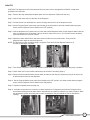
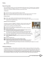
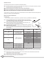
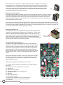
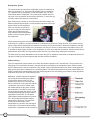
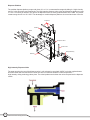
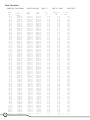
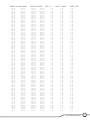
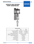
BUNN® TECHNICAL TRAINING
JDF Silver Series
Index
Unit 1: Installation
Site Requirements............................................................................................................... 4
Prepping Machine for Install.............................................................................................. 4
Install Outer Door Cover..................................................................................................... 4
Water Supply Install............................................................................................................ 4
Install the Air Filter.............................................................................................................. 4
Initial Fill............................................................................................................................... 5
Unit 2: Setup
Product Preparation............................................................................................................ 7
Load Product................................................................................................................. 7
Prime the Pumps........................................................................................................... 7
Calibrate the Machine......................................................................................................... 7
Calibration Process...................................................................................................... 7
Water Flow Test and Adjustment................................................................................. 7
Total Dispense Test....................................................................................................... 8
Pump Speed Adjustment.............................................................................................. 8
Set the Portion Control Option........................................................................................... 8
Portion Control Option for Mechanical Buttons and P/H Buttons........................... 8
Portion Control (P/C) Membrane Button..................................................................... 9
Unit 3: Machine Composition
Exterior Overview................................................................................................................ 11
Product Outlets and Removable Parts....................................................................... 11
User Interface................................................................................................................ 11
Product Cabinet................................................................................................................... 11
Accessing the Inside of the Machine................................................................................. 12
Removing the Door Cover.................................................................................................. 12
Machine Function and Operations..................................................................................... 12
Electronic Group........................................................................................................... 12
Door Assembly.............................................................................................................. 14
Refrigeration System.................................................................................................... 14
Cabinet Cooling............................................................................................................ 15
Water Tank Assembly................................................................................................... 16
Water Delivery............................................................................................................... 16
Dispense Platform........................................................................................................ 16
Unit 4: Preventive Maintenance
Tools Required..................................................................................................................... 19
PM Steps.............................................................................................................................. 19
Unit 5: Troubleshooting
LED Indicator Chart............................................................................................................. 23
Accessing the LED’s........................................................................................................... 23
Mechanical or Refrigeration Failure.................................................................................. 24
Rev. B
© 2011 Bunn-O-Matic Corporation. All Rights Reserved
Unit 1 Installation
Unit Objectives
Given a realistic scenario depicting a new site install, the learner will be able to install and setup the
dispenser for customer turnover without error.
Given a new machine, all the necessary tools and safety equipment, the learner will be able to install the dispenser without error.
The learner will be able to verify that the site requirements have been met.
The learner will be able to prepare the machine for install.
The learner will be able to install the outer door cover.
The learner will be able to hook up the water supply.
The learner will be able to install the air filter.
The learner will be able to perform the initial fill.
Installation
Site Requirements
Space
• Counter able to support 150 lbs. (68 kg)
• Minimal clearance is required between the machines side and the wall or another appliance
• Minimum clearance of 4” behind machine
• Minimum clearance of 8” above machine
• JDF-2S approx. dimensions (H 33 x W 10 x D 25.5)
• JDF-4S approx. dimensions (H 33 x W 16 x D 25.5)
Plumbing
• 3/8” flare water connection
• Water supply must be capable of producing 3 fluid oz. a sec
• A shut-off valve should be installed in the line before the machine
• Connected to cold water
• Water pressure 20-100psi, set to 50psi if regulator is needed
Electrical
• 115VAC/208VAC
• Dedicated 20AMP Circuit with proper breaker and receptacle
• Receptacle within 5 feet of machine
Prepping Machine for Install
Step 1: Verify that all of the site requirements have been met.
Step 2: Unbox the machine and all the parts.
Step 3: Place the machine in the desired location on the counter.
Step 4: Document the complete serial number of the machine.
Install Outer Door Cover
Step 1: Connect the ribbon cables from the door cover to the control board. When connecting the ribbon cables
ensure that the number on the cable is at the top of the ribbon. For models without the portion control option you will only need to connect the door and the door cover with a molex connector.
Step 2: Place door cover over the door.
Step 3: Secure the door cover to the door using the five screws provided.
Water Supply Install
Step 1: Flush water lines.
Step 2: Attach to the fitting at the rear of the machine.
Step 3: Turn on water and check for any kinks or leaks in the line.
Install the Air Filter
Step 1: Locate the filter and the Velcro strips supplied.
Step 2: Place Velcro strips on the filter and on the coils at the rear of the machine.
Step 3: Secure the filter to the machine using the Velcro.
After you have install the air filter verify that the refrigeration switch is in the off position.
4
JDF Silver Series Training Manual
Initial Fill
CAUTION: The dispenser must be disconnected from the power source throughout the initial fill, except when
specified in the instruction.
Step 1. Remove drip tray assembly and splash panel from the dispenser. Replace the drip tray.
Step 2. Connect the water source to the back of the dispenser.
Step 3. Pull the fill tube from the dispenser, remove the plug and connect it to the dispense nozzle.
Step 4. Set the Program Switch (near main control board) to the ON position. (On older models without program switch, set the Dispense Lockout Switch to the OFF position)
Step 5. Connect dispenser to the power source. Press and hold the dispense button for the dispense station that the tube is connected to for 10 seconds, until you hear the water valve turn on. (For Portion Control machines, press and hold the PLUS/STOP switch)
Step 6. Monitor the water bath fill level until water starts to trickle from the overflow tube. Then press the dispense button again to stop the fill process.
NOTE: The fill timer may time out before filling is complete. Press and hold the dispense button for 10
seconds to start again if needed.
Step 7. Turn ON the refrigeration switch near the main control board. This will start the water bath pump circulation.
Step 8. Check water level in the overflow tube and top off the tank if necessary (Step 5).
Step 9. Disconnect the fill tube and allow excess water to drain into the drip tray. Replace the plug in the end of the fill tube and store back into the dispenser.
Step 10. Set the Program Switch (near main control board) to the OFF position. (On older models without program switch, set the Dispense Lockout Switch to the ON position)
Step 11. Replace the splash panel and drip tray.
Step 12. It will take several hours to create the ice bank required for full dispenser performance. During this time, some further trickling from the water bath is expected due to expansion caused by ice bank formation. While the refrigeration system is creating the ice bank, the dispenser may be readied for use as described in
Loading,
5
Bunn-O-Matic Corporation
Unit 2 Setup
Unit Objectives
Given a realistic scenario depicting a new site install, the learner will be able to install and setup the dispenser for customer turnover without error.
Given an installed machine, all the necessary tools and safety equipment, the learner will be able to set the machine up for initial operation.
The learner will be able to load the product.
The learner will be able to prime the pumps.
The learner will be able to perform a water flow test and adjustment.
The learner will be able to perform a total dispense test.
The learner will be able to perform a pump speed adjustment.
The learner will be able to set the portion control option.
Setup
Product Preparation
Prior to calibrating the machine you must first load product and prime the pumps. The product must be completely
thawed and be within the temperature range of 35º - 40º F. If the product is not within the acceptable temperature
range you will not be able to calibrate the machine to the product correctly.
Load Product
Step 1: Mix the product by vigorously shaking the product container.
Step 2: Wet or use a food grade lubricate on the container o-ring. This will ease removal of the container.
Step 3: Place the product in the cabinet and press it firmly into the bottle adapter opening.
Prime the Pumps
Step 1: Place a large container under dispense nozzle for the pump you wish to prime.
Step 2: Press and hold the dispense button, (“Stop/Plus” button if using portion control option), until concentrate dispenses from the dispense nozzle.
Ambient Conversion Kit (Optional)
The ambient conversion kit, (BUNN P/N: 33699.0001), allows remotely located ambient
concentrate products to be used in place of dispenser mounted frozen concentrate
products. One kit is required for each dispense station.
Step 1: Disconnect the dispenser from the power source.
Step 2: Remove the right side panel. Set the panel and screws aside for re-assembly.
Step 3: Open the dispenser door.
Step 4: Remove the decorative plugs from convenient openings at the right rear of the refrigerated compartment and the dispenser’s rear panel.
Step 5: Feed the free end of the Convertible Tube Assembly’s concentrate tube through the openings in the refrigerated compartment and dispenser rear panel. Take care to route Tube Assemblies so they won’t kink or interfere with the condenser fan.
Step 6: Connect the concentrate container to the free end of the concentrate tube protruding from the dispenser’s rear panel.
Step 7: Insert the Adapter end of the Convertible Tube Assembly into the desired bottle
interface.
Step 8: Close the dispenser door.
Step 9: Install the right side panel with the screws set aside in Step 2.
Step 10: Apply power to the dispenser and prime the dispense tubing.
Step 11: Open the dispenser door and check for any signs of air bubbles in the dispense tubing. Any bubbles indicate the presence of a vacuum leak. When bubbles are
present, re-check the fastening of all clamped connections, and positioning of the Adapter into the bottle interface.
Step 12: Close the dispenser door.
Calibrate the Machine
To calibrate the JDF Silver Series machines you will need to complete a couple of procedures. The first procedure
required during calibration is to determine you water flow rate. This is accomplished by conducting the water flow test
to identify your known volume of water being dispensed. The next procedure in the calibration process would be to
conduct the total dispense test. You will then need to locate your product mix ratio, (usually found on the product container). Using the total dispense ratio chart found in the “Installation and Operating Guide” you will need to determine
if your total dispense matches your ratio target, if it does not you will need to make a pump speed adjustment.
7
Bunn-O-Matic Corporation
Calibration Process
The following process needs to be completed for all dispense stations.
Step 1: Identify the desired mix ratio for the product being used, (usually found on the product container), and mark the product ratio on the total dispense ratio chart.
Step 2: Conduct water flow test to determine known volume of water dispensed.
Step 3: Perform total dispense test to determine total volume of water and product dispensed.
Step 4: Use the total dispense ratio chart to determine if total dispense matches the ratio target.
Step 5: Make pump speed adjustment if total dispense does not match desired ratio target.
The procedures for conducting a water flow test, and total dispense test are explained in detail below along with the
procedure for making a pump speed adjustment.
Water Flow Testing and Adjustment
Tools Required:
• 64 ounce pitcher (BUNN P/N: 04238.0000) or graduated measuring cup (BUNN P/N: 33095.0000).
Step 1: Place a graduated measuring cup or the large chamber of the empty brixing cup (BUNN-O-MATIC part number 33095.0000) under the appropriate dispense nozzle. Place the Program switch in the ON position.
Step 2: Press and release the desired “Product Dispense Switch” three times. (On
Portion Control models, use the plus/stop switches)
Step 3: The selected position will dispense water (no concentrate) only for 3 seconds.
Step 4: Measure the water dispensed.
Step 5: Adjust the water flow rate with a 1/4 allen wrench, (clockwise to increase flow rate; counterclockwise to decrease flow rate) to the corresponding product mix ratio as follows:
Mix Ratio
(water + concentrate)
2+1
Adjust water flow rate to:
Product
Brix %
*3.75 fl. oz (111 ml)
per 3-second test
Prune Juice
Other
Orange Juice
Pineapple Juice
Cranberry Fruit Cocktail
Grapefruit Juice
Lemonade
Apple Juice
Fruit Punch
Grape Juice
Other
Other
16.0%
*
11.8%
12.8%
14.0%
10.6%
As Required
-
4+1
5+1
3+1 through 7+1
Above 7+1
High Viscosity Juice
*4.0 fl. oz (118 ml)
per 3-second test
*4.0 fl. oz (118 ml)
per 3-second test
2.25 - 3.0 fl. oz (66.5 - 89 ml)
per 3-second test
12.0%
13.0%
*
*
*Maximum flow rate may be less depending on the water pressure supply at each location.
Note: Information for specific products listed in this table is to be used for reference only. Consult the product label for
exact mix ratio and/or brix %. See product label for target brix %.
Step 6: Repeat steps 1 through 5 as necessary until the correct water flow rate is achieved and record the total
dispensed water for each dispense station.
Step 7: Repeat steps 1 through 5 for the remaining dispense positions.
Step 8: Place the Program switch back into the OFF position.
8
JDF Silver Series Training Manual
Total Dispense Ratio Set Up Procedure
Tools Required:
• 64 ounce pitcher (BUNN P/N: 04238.0000) or graduated measuring cup (BUNN P/N: 33095.0000).
Step 1: Reference recorded total dispense water for each dispense station.
Step 2: Place the Program switch in the ON position.
Step 3: Place a measuring container under the dispense nozzle, press and release the DISPENSE button 6 times.
Step 4: Record the total ounces dispensed.
Step 5: Refer to the Brix/Ratio chart below to confirm proper total dispensed amount for ratio desired and water out
put previously recorded.
Step 6: To increase or decrease the product output, refer to Pump Speed Adjustment section.
Step 7: Place the Program switch back into the OFF position.
If the total dispensed liquid does not match the desired total volume based on your mix ratio and water flow rate, you
will need to make a pump speed adjustment.
Pump Speed Adjustment
Tools Required:
• Standard screwdriver
Step 1: Disconnect the machine from the power source.
Step 2: Remove the drip tray.
Step 3: Remove the two screws that secure the splash panel and remove the splash panel.
Step 4: Locate the adjustment knobs on the circuit board.
Step 5: The knob positions directly correspond to dispense station locations. Turn the adjustment knob
associated with the dispense station you wish to adjust, clockwise to increase the pump speed and counter
clockwise to decrease the pump speed. Increasing the pump speed will increase the amount of product
dispensed giving you a higher total dispense, decreasing the pump speed will have the opposite affect.
Note: Some 2-S models will have 4 adjustment knobs on the circuit board. For these models, use the two left most
knobs to make a pump speed adjustment.
Step 5: Reinstall the splash panel and drip tray, then reconnect the dispenser to the power source.
Set the Portion Control Option
The product dispense buttons, for machines using mechanical buttons or membrane buttons, can be set for a
portioned dispense. The mechanical buttons and the P/H membrane buttons have the option to be set with a single
portioned dispense on one or all of the dispense heads. Machines with the P/C membrane buttons are preset at the
factory but can be adjusted to meet the customers requirements. The P/C membrane switches can be set for push
and hold dispensing by programming the dispenser to dispense for less than two seconds.
Portion Control (P/C) Membrane Button
Portion sizes are preset but can be adjusted by following the steps below.
Step 1: Set the program switch (near the main control board) to the ON position (on older models without the
program switch, set the dispense lockout switch to the OFF position.
Step 2: Press and hold the large and medium buttons on the left most (Station #1) dispense station until you hear the machine “beep”.
Step 3: Place a measuring container under the station to be adjusted, then press and hold the appropriate dispense switch until you reach the desired amount of product in the measuring container. The machine will record the amount of time that the button is pressed continuously. If the button is released too soon, simply empty the container and start over.
Step 4: Repeat step 3 for all stations as desired.
Step 5: Turn the program switch to the OFF position.
9
Bunn-O-Matic Corporation
Ratio Target Chart
3 Second
Water
Dispense
(oz.)
Ratio Target
2:1
3:1
4:1
5:1
6:1
7:1
8:1
9:1
10:1
11:1
12:1
13:1
14:1
15:1
1.5
2.25
2.00
1.88
1.80
1.75
1.71
1.69
1.67
1.65
1.64
1.63
1.62
1.61
1.60
1.75
2.63
2.33
2.19
2.10
2.04
2.00
1.97
1.94
1.93
1.91
1.89
1.88
1.88
1.87
2.0
3.00
2.67
2.50
2.40
2.33
2.29
2.25
2.22
2.20
2.18
2.17
2.15
2.14
2.13
2.25
3.38
3.00
2.81
2.70
2.63
2.27
2.53
2.50
2.48
2.45
2.44
2.42
2.41
2.40
2.5
3.75
3.33
3.13
3.00
2.92
2.86
2.81
2.78
2.75
2.73
2.71
2.69
2.68
2.67
2.75
4.13
3.67
3.44
3.30
3.21
3.14
3.09
306
3.03
3.00
2.98
2.96
2.95
2.93
3.0
4.50
4.00
3.75
3.60
3.50
3.43
3.38
3.33
3.30
3.27
3.25
3.23
3.21
3.20
3.25
4.88
4.33
4.06
3.90
3.79
3.71
3.66
3.61
3.58
3.55
3.52
3.50
3.48
3.47
3.5
5.25
4.67
4.38
4.20
4.08
4.00
3.94
3.89
3.85
3.82
3.79
3.77
3.75
3.73
3.75
5.63
5.00
4.69
4.50
4.38
4.29
4.22
4.17
4.13
4.09
4.06
40.4
4.02
4.00
4.0
6.00
5.33
5.00
4.80
4.67
4.57
4.50
4.44
4.40
4.36
4.33
4.31
4.29
4.27
4.25
6.38
5.67
5.31
5.10
4.96
4.86
4.78
4.72
4.68
4.64
4.60
4.58
4.55
4.53
4.5
6.75
6.00
5.63
5.40
5.25
5.14
5.06
5.00
4.95
4.91
4.88
4.85
4.82
4.80
4.75
7.13
6.33
5.94
5.70
5.54
5.43
5.34
5.28
5.23
5.18
5.15
5.12
5.09
5.07
5.0
7.5
6.67
6.25
6.00
5.83
5.71
5.63
5.56
5.50
5.45
5.42
5.38
5.36
5.33
Dispensed Product (oz.)
10
JDF Silver Series Training Manual
Unit 3 Machine Composition
Unit Objectives
Given a realistic scenario in which the learner has access to the machine’s internal components the learner
will understand the composition and functions of the dispenser.
Given a realistic scenario requiring the learner to access the internal components of the machine the learner will be able to remove panels.
Given an operating machine the learner will be able to give a general explanation of how the unit operates.
The learner will be able to identify major components in the machine and describe their
functions.
The learner will be able to explain how the components work in relation to the system.
The learner will be able to explain how the systems work in relation to the machine.
Machine Composition
Exterior Overview
Inlets, Control Switches, Product Outlets, and Removable Parts
•
•
•
•
•
•
•
Water Inlet
Air Filter
Dispense Lockout Switch
Dispense Nozzle (Quick Stop)
Drip Tray
Splash Panel (electrical schematic is located on backside of splash panel)
Cold Water Nozzle (option only available JDF-4S)
Air Filter
Dispense Nozzle
Splash Panel
Drip Tray
User Interface
The user interface allows the customer to dispense a beverage.
Product Cabinet
This houses the product and keeps it cool by maintaining a cabinet temperature range of
35º to 41º F. If the customer wishes to use ambient concentrates you will have to install
the optional Ambient Concentrate Conversion Kit.
12
JDF Silver Series Training Manual
Water Inlet
Accessing the Inside of the Machine
The majority of service work done to a JDF-S will require the service technician to access the inside of the unit. The
unit has four removable panels to facilitate access- the top panel, the two side panels, and front splash panel. Depending on the repair the technician may have to remove one or all of these panels.
In order to work safely the power should be disconnected prior to removal of any body panel. Once the panels
are removed the power can be reconnected in order to
troubleshoot the machine.
Top Lid
Rear Panel
Ambient
Product Line
Entry
Air Filter
Right Panel
Top Panel
The top panel is secured with 4 small flat head screws.
To the remove the panel, remove the four screws, lift
the panel up and away from the dispenser’s body.
Lower
Splash Panel
Side Panels
Each side panel is secured with 4 small flat head
screws. Once the screws have been removed pull the
side panel away from the dispenser.
Front Splash Panel
This panel can be removed by first removing the drip
tray to gain access to the two screws securing the
splash panel in place. Remove the 2 flat head screws
then slide the splash panel down the pull away from the
dispenser.
Serial Number &
Data Plate
Refrigeration
Charge Decal
Left Panel
Drip Tray & Grate
Removing the Door Cover
Bezel Retainer
Door Cover
The door cover may be removed if you need to gain access to the lighting
circuit, switches, switch board or membrane switches.
Step 1: Disconnect unit from power source.
Step 2: Remove the 5 screws securing the door cover to the door assembly.
Step 3: If unit uses a membrane switch disconnect the 6 pin connectors from
auxiliary switch board. If the unit uses mechanical switches disconnect at the
harness molex pin connector.
Step 4: Set door cover aside.
Flavor Label
Holder
Bezel
Machine Function and Operations
Portion Control
Switch Membrane
Electronic Group
Step Down Transformers (A and B)
The top step down transformer connects to J-12 connector, marked
“Right Power” on control board. The transformer is responsible for
operating dispense stations 3 and 4 known as right middle and
right dispense stations.
The bottom step down transformer connects to the J-6 connector,
marked “Power” on the control board. The transformer is responsible for the main power for the control board, machine and dispense
stations 1 and 2 known as left and left middle.
F
A
G
E
H
B
I
D
C
13
Bunn-O-Matic Corporation
Both transformers are 120VAC on the primary side and step the voltage down to 24VAC on
the secondary side of the transformer. Each transformer is protected on the “load” side with
a resettable PTC fuse. The Poly Switch Polymeric Positive Temperature Coefficient (PPTC)
device used on the load side of the transformers will help protect against harmful over/current surges, voltage and over/temperature faults. The PPTC device will reset after the fault
is cleared and power to the circuit is removed.
PPTC
Dispense Lockout Switch (C)
The dispense lockout switch is located on the bottom front behind the drip tray. The switch is used to
lockout the dispense functions of the dispenser to prevent unauthorized use of the dispenser, while
keeping the refrigeration system running. Early juice machines before the release of the program
switch also used the dispense lockout switch to enter the water bath fill mode, semi-automatic sanitizing mode and brixing test modes.
A field retrofit kit is available to convert old style JDF-S machines to the new style should a customer request it. The
PN for the retrofit kit is 44140.0000 and applies only to mechanical switch dispensers. At this time a kit is not offered
for membrane switch models. Installation of the retrofit kit is considered elective and is not covered by warranty. Refer to service bulletin 189 for details regarding the change.
Relay Contact
Compressor Relay K1 (D)
The compressor relay is the component that will pass 120VAC power to the
compressor. By switching the refrigeration to the on position, 120VAC will be
present on one contact terminal waiting to pass on. The relay coil (K1) will
receive 120VAC from the main control board after a 6 minute delay from initial
plug-in and energize, closing the relay contacts. With the contacts closed
120VAC will pass across the contact and onto the compressor limit thermostat
and energize the compressor start and run winding.
Relay Coil - Labeled K1
On Wiring Schematic
Control Board Assembly (CBA) (E)
The CBA is powered by receiving 24VAC from one of the step down
transformers. The CBA microprocessor will receive input signals and in
return will control a sequence event or an output of power to the other
components used throughout the machine. The CBA is responsible of
converting 24VAC to D/C voltage to support the voltage adjustment
dials located at the bottom of the CBA for the pump motor rpm ,cabinet
fan and dispense valve. The pump speed adjustment dials range 9 to
24VDC.
J1
1
2
3
4
5
J2
4
5
6
J13
1
2
3
Other power distributed is 120VAC to inlet valve, compressor run relay,
transformer and condenser fan motor. The CBA will further step down
the voltage to 5VDC for door switches, dispense lockout switch and
water and bath thermistor.
J3
1 2
J11
CBA Connector Identification (BUNN P/N: 40177.1000)
14
J-1: 120VAC supply to the CB for inlet water valve, 120VAC output to
water valve
J-2: Pump motor 1 and 2 and water valves 1 and 2
J-3: Cabinet fan
J-5: Dispense lockout switch
J-6: Power/Lower transformer (Transformer B)
J-7: Cabinet thermistor
J-8: Not used
J-9: Water bath thermistor
J-11: Door auxiliary board
J-12: Right power for stations 3 and 4 (Transformer A)
J-13: Pump motor 3 and 4 and water valves 3 and 4
J-15: Not used
JDF Silver Series Training Manual
6
5
4
3
2
1
1
2
3
4
5
J12
J7
J15
1 2
J9
2 1
J5
2 4
3 2 1
1 3
J6
1
Left
Station
J8
3
2
1
1
2
2
Middle Left
Station
3
Middle Right
Station
4
Right
Station
Connectors and pump speed dials not present on JDF-2 S, CBA (BUNN P/N: 40177.1001)
• J-12
• J-13
• J-15
Pump Speed Dial 3 and 4
Refrigeration Switch (F)
The refrigeration switch is located behind the splash panel next to the circuit board. This switch
passes 120VAC power to the water bath pump and compressor K1 relay contact terminal.
Program Switch (G)
The program switch is located near the main control board next to the refrigeration switch.
The program switch is used to enter timed fill mode, brix test modes and to access the semiautomatic sanitize mode while the dispense lockout switch is in the ON position.
Step Down Transformer for Lighted Display (H)
This step down transformer is rated for 115 Primary/24 Secondary volts with a 40 VA rating. The
maximum current on the secondary winding is 1.6 Amps. Transformers are power rated in VA
(volts x amps) and applies to both the primary and secondary winding. The secondary voltage
24VAC goes to a rectifier before going to a single or two ballasts located on the inner door panel.
Rectifier (I)
The rectifier receives the 24VAC from the step down transformer and converts the 24VAC over to
24VDC before going on to the door light ballasts rated at 24VDC.
Door Assembly
The door gasket is mounted and foamed in place to the inner door. Early models with fluorescent lamps may contain
one or two ballasts mounted on the inner door panel or the latest version being LED lighting. See BUNN service
bulletin 175 about converting fluorescent lighting to LED lighting. The switch circuit board, which communicates with
the main CBA, is isolated and mounted to the inner door panel. The portion control switch membranes connect to
the switch board in logic order from left to right. The user can initiate a portion dispense of product or has the ability
to set the small, medium and large
Door Gasket
buttons as press and hold during
Door Latch
setup. When a membrane switch is
depressed a low input signal is sent to
the switch circuit board. The input is
then communicated to the CBA where
appropriate output voltages are distributed to the components used during
dispense.
Note: Switch circuit board is not used
or present on juice machine that use
mechanical switch buttons in the outer
door cover.
LED Circuit
Board
Inner
Door
Door Harness
Slot
Circuit Board
LED Lights
Label Holder
Dual Ballast Doors
Bezel
P/C Switch
Membrane
15
Early Models with Flourescent Bulbs
Bunn-O-Matic Corporation
Refrigeration System
The components that make up the refrigeration system to create an ice
bank are compressor (1), filter dryer with capillary tube (2), condenser
(3), condenser fan (4), evaporator (5) and accumulator (6). The other
components that are responsible for monitoring the ice bank and turning on/off of the compressor are as follows; thermistor (7), start relay (8),
run relay, transformer and main control board.
Upon initial plug-in or power up, the main control board will monitor the
bath thermistor and go through a six minute delay sequence before supplying 120VAC to the compressor
relay coil. After the six minute delay, the run relay coil will energize,
power cannot pass through the
relay contacts until the refrigeration
switch is turned to supply power to
the compressor.
Power passes through the limit thermostat and powers the start relay mounted on the compressor. The unit will take
several hours to create the ice bank required for full dispenser performance. During this time, some further trickling
from the water bath is expected due to expansion caused by the ice bank formation. When the temperature reaches
27º F, this will shut off the 120VAC to the compressor run relay coil. As the ice block thaws, temperature rises to 32º
F, the CBA will again supply 120VAC to the compressor run relay coil to start the compressor. Anytime the machine is
powered down electrically, the refrigeration system will have a six minute delay starting the compressor.
The delay ensures enough allowable time for the start relay (PTC) resistance to decrease to complete the start winding path for initial start up and refrigerant high and low pressure to stabilize.
Cabinet Cooling
First, the refrigeration system creates an ice block around the evaporator coil in the bath tank. The top load recirculating pump is mounted semi-centered in the bath tank and is activated by the refrigeration switch. Water is drawn
from the bath tank up to the top connection of the cabinet cooling coil and at the same time water is being bypassed
going directly back into the bath tank for increased agitation. The chilled water passes through the cabinet water coil
picking up heat before returning back to the bath tank along side of the recirculating pump. Water is being bypassed
at all times during this 24/7 recirculation process.
Meanwhile, a 24VDC cabinet fan operates
24/7 pulling and recirculating the cabinet
air across the cabinet water coil. This
speeds up the process of removing heat
from the cabinet air or decrease the cabinet
temperature. A thermistor located inside
the cabinet behind the fan panel monitors
the temperature. The CBA will receive the
low input voltage signal and will turn on the
corresponding temperature LED’s located
at the bottom of the CBA. The #5 green
LED indicates cabinet temperature is below
50º F and #4 red LED indicates cabinet
temperature is above 50º F. A thermistor
can also be used to detect rise in
temperature for a period of time and signal
a fault status. The nominal cabinet holding
temperature is expected to be at or below 41º F.
16
JDF Silver Series Training Manual
Pump Assembly Bypass
The bypass holes are used for increased agitation in the water tank which has
an additional purpose of enhancing the performance and burst capacity of the
machine. Both pumps are identical in appearance but have two different service
replacement part numbers. Single hole is used in the JDF-2S and the two hole
bypass is used in the JDF-4S.
Water Tank Assembly
The water tank is used for the purpose of containing the nonpotable water in the development of the ice block and the
process of cooling the potable water in the water coil that will
be used for the purpose of product dispense. In addition, the
chilled non-potable water in the tank is used for the method
of cooling the upper cabinet to keep product at refrigerated
temperature. The size of the tank and ice block relate to the
meaning of burst capacity. Burst capacity refers to the number
of drinks/volume that can be produced without exceeding 41º
F finished drink temperature within a time frame.
Water Return Manifold
Water Coil
Evaporator
Draining Water Tank
The unit will need to be unplugged or refrigeration switch
turned off for a period of 48 hours for the ice block to thaw.
After thaw, remove sight gauge tube from retaining clip and
lower the tube below tank level and the tank will begin draining water out of the sight gauge tube.
Overflow Tube
Cabinet
Drain Line
Sight Gauge
Fill Tube
Water Delivery
When a user depresses a button or membrane on the door an input signal is sent to the CBA. In return the CBA will
send out the corresponding output to turn on the water inlet valve, dispense motor and dispense valve to begin dispense or portion dispense. The water goes through a strainer and is regulated to 2.0gpm by the flow restrictor in the
inlet valve. The water flows through the cold water coil that is submerged in the cold water tank and enters the back
of each dispense valve.
All dispense valves have a water flow
rate adjustment to assist in the calibration or ratio set-up of product. Primarily the water is factory set and the
concentrate is adjusted for ratio set-up
by pump motor rpm. The concentrate
and water mixes in the High Intensity
dispense valve and is being delivered
out the quick stop nozzle.
The optional cold water dispense is
only available on the JDF-4S.
Optional/Cold
Water Valve
Water Inlet Valve
Cold Water Nozzle
Water Coil
Dispense Valve
17
Bunn-O-Matic Corporation
Dispense Platform
The modular dispense platform pumps and mixes 2+1 to 11+1 concentrated beverages including 4+1 high viscosity
and 5+1 juices accurately and consistently. The High Intensity dispense valve mixes and dispenses product at a rate
of 1.0 to 1.5 ounces per second. The rpm for the dispense motor are set by potentiometers on the CBA. The potentiometers range from 9.0 to 25.0 VDC. The advantage to modular dispense platforms is removal and ease of service.
Product In
Water In
Motor
Dispense Valve
Product Out
Pump Assembly
Platform
High Intensity Dispense Valve
The water entering the rear of the dispense valve is coil activated or energized (24VDC) to let the regulated water
flow travel down the stem and out the narrow slot as the concentrate enters the valve body and the
High Intensity mixing technology takes place. The mixed product travels down the valve ramp and out the dispense
nozzle.
18
JDF Silver Series Training Manual
Unit 4 Preventive Maintenance
Unit Objectives
Given a realistic scenario depicting a machine requiring a preventive maintenance, the learner will be able to
identify which elements of a component need to be serviced without error.
Given a machine, all the necessary tools and safety equipment, the learner will be able to identify the components that need to be serviced for the PM.
Preventive Maintenance
In order to maintain proper operation and long service life BUNN recommends performing the preventive maintenance every 6 months. Individual customers will vary with some customers choosing not to receive preventive maintenance. Some of the PM items may require more frequent maintenance depending on the site conditions.
Tools Required:
• Standard screwdriver
• 8 inch crescent wrench (2)
• Needle Nose Pliers
• Velcro Tape
• Graduated measuring cup
• Refractometer
• Thermometer
• Flashlight
• 5 gal. bucket
• Tube PM Kit BUNN PN: 39690.0000 (1 per dispense station)
• Kay-5 Sanitizer (50 Count BUNN P/N: 24634.0001) (200 Count BUNN P/N: 24634.0000)
• BUNN refillable container (BUNN P/N: 39302.0000)
• Condenser Cleaner
• Rubber gloves
• Safety goggles or face shield
• Fin Comb
• Mild non abrasive detergent and cloth
• Vacuum with soft brush attachment
Prior to servicing the dispenser:
• Sanitize the dispenser before you begin the preventive maintenance process.
• Disconnect the water and electrical supply.
• Assess placement of dispenser to perform PM process.
• Check and make sure you have the necessary safety equipment for cleaning the condenser.
• Remove the lower splash panel.
• Remove the right side panel.
PM Steps
Step1: Remove inlet valve connector fitting and clean inlet valve strainer.
□□ Using your hand and unscrew the valve adapter fitting and set aside.
□□ Using the needle nose pliers gently grab the strainer tab and pull the strainer out of the valve.
□□ Clean and rinse strainer of any sediment or mineral build-up.
□□ Re-installation is the opposite of removal.
Step 2: Replacement of lamp in lighted door assembly.
□□ Using a standard screwdriver, remove the five screws securing the outer door cover to the inner door.
□□ Disconnect the door switch connector or connectors from the auxiliary switch CBA and set door cover aside.
□□ Gently grab the failed lamp and rotate half turn until lamp connection studs are aligned up with lamp socket opening and remove lamp.
□□ Re-installation of new lamp is the opposite of removal.
Step 3: Remove and clean the mesh air filter.
□□ Using your hand, grab the mesh filter triangle handle and pull the air filter from the dispenser.
□□ Wash the air filter in warm soapy water and dry.
□□ Using a flashlight, shine the light through the condenser to check for dirt between the fins. Inspect condenser fins for straightness. Go to the next step of Cleaning the Condenser.
□□ Inspect Velcro straps for adhesion to air filter and dispenser and be ready to replace after cleaning of the condenser.
Step 4: Cleaning the condenser.
□□ Using a soft cleaning brush attachment, gently vacuum the condenser coil fins.
20
JDF Silver Series Training Manual
□□ Using a flashlight, shine the light through the condenser fins to re-check for cleanliness or dirt between the fins.
□□ Heavy build-up of grease in the condenser may require the use of a commercial condenser cleaner.
□□ Follow the manufacture warning and safety instructions along with how to instructions supplied with the cleaner.
Step 5: Replacing the peristaltic pump tubing.
□□ Open dispenser door.
□□ Remove all product containers and place them in a refrigerated, (35-40º F [1.6-4.4º C]), environment. Disconnect all connections to ambient products from the bottle adapter.
□□ Rinse all dispense stations using steps outlined in “DAILY RINSE PROCEDURE” in the operating manual.
□□ Disconnect dispenser from power source.
□□ Remove the dispense platform cover.
□□ Disconnect the dispense platform water line(s) from the supply line inside the refrigerated cabinet and disconnect the wiring connection(s) from the cabinet receptacle(s).
□□ Remove the mounting screw(s) securing the dispense platform(s) to the cabinet.
□□ Pull the dispense platform(s) completely out of the cabinet and place it on a flat work surface.
□□ Close the dispenser door.
□□ Remove the 4 screws securing the pump head.
□□ Gently pull the pump head apart.
□□ Gently pull the pump tube from around the pump’s rotor.
□□ Release the clamps securing the old pump tubing to the plastic elbows.
□□ Pull the plastic elbows from the old pump tubing, and discard the old pump tubing.
□□ Insert the plastic elbows into the new pump tubing and secure it with the clamps.
□□ Gently wrap the new pump tubing around the pump’s rotor.
□□ Reassemble the pump housing onto the platform assembly.
□□ Repeat this process for the remaining pumps.
□□ Replace the dispense platform(s) into the refrigerated cabinet, making sure to reconnect all electrical and water connections.
□□ Replace the dispense platform cover.
□□ Turn power on to dispenser.
□□ Install containers of rinse water, run each station and check for leaks. Repair leaks as necessary.
□□ Replace product shelf and product containers. Reconnect any connections to ambient product containers.
□□ Prime the pumps.
Step 6: Follow the daily parts washing procedure in the operating manual.
□□ Remove and wash the dispense nozzle(s); mixing element(s), drip tray and drip tray cover in a mild detergent solution. Rinse thoroughly.
□□ Wipe splash panel, areas around dispense nozzle(s), and refrigerated compartment with a clean, damp cloth.
□□ Inspect door seal gasket for wear and cleanliness.
Step 7: Examine all electrical connections and power cord for loose connection.
Step 8: Examine all water lines and supply for leakage.
Step 9: Check cabinet temperature with thermometer (Note: The dispenser must be on to perform this step).
□□ Install thermometer in cabinet and monitor temperature to see if it comes down below 41 degrees Fahrenheit. Good idea always to leave thermometer in cabinet to monitor proper cooling process and temperature.
□□ Check for proper air flow inside cabinet around product.
Step 10: Check product mix brix/ratio in their corresponding dispense station (Note: The dispenser must be on to
perform this step).
□□ Water Flow Test and Adjustment
Step 1: Place the pitcher beneath the dispense nozzle you are testing.
Step 2: Place the “Dispense Lockout” switch in the Off position and access the internal program switch and
turn it ON.
Step 3: Press and release the appropriate dispense button, (“Stop/Plus” button if using portion control
option). The machine will dispense water from the dispense nozzle for 3 seconds.
Step 4: Measure the water dispensed.
Step 5: Adjust the water flow if needed, (see water flow chart in the “Installation and Operating Guide”). Clockwise will increase flow rate and counterclockwise will decrease the flow rate.
Step 6: Mark the quantity of water dispensed on the total dispense ratio chart.
Bunn-O-Matic Corporation
21
□□ Total Dispense Test
Step 1: Place the pitcher beneath the dispense nozzle you are testing.
Step 2: Place the “Dispense Lockout” switch in the Off position and access the internal program switch and turn ON.
Step 3: Press and release the dispense button, (“Stop/Plus” button if using portion control option), 6 times.
Step 4: Measure the amount of liquid dispensed.
Step 5: Mark the quantity of liquid dispensed on the total dispense ratio chart.
□□ Pump Speed Adjustment
Step 1: Disconnect the machine from the power source.
Step 2: Remove the drip tray.
Step 3: Remove the splash panel by removing the screws holding it in place.
Step 4: Locate the adjustment knobs on the control board. Turn the knob, associated with the dispense station you wish to adjust, clockwise to increase the pump speed and counterclockwise to decrease the pump speed. Increasing the pump speed will increase the amount of product dispensed giving you a higher total dispense, decreasing the pump speed will have the opposite affect.
Step 5: Conduct the total dispense test to determine if more of an adjustment is needed. If no further
adjustments are required, turn OFF the program switch and re-install the lower splash panel.
□□ Temperature Compensated Refractometer Method
Step 1: Adjust the water flow as described in Water Flow Test and Adjustment.
Step 2: Place an empty container under the appropriate dispense nozzle.
Step 3: Press and hold the “Product Dispense Switch”, until water and concentrate begin flowing freely from the dispense nozzle.
Step 4: Discard the product caught previously and place the empty container back under the dispense nozzle.
Step 5: Press and hold the “Product Dispense Switch” until the cup is filled.
Step 6: Stir the contents of the cup, and use the refractometer (according to the manufacturer’s instructions) to check the brix %.
Step 7: Adjust the pump speed (down to decrease the brix %; up to increase the brix %) to achieve the
correct brix % as described in Pump Speed Adjustment.
Step 11: If customer has a BUNN water filtration system installed before the dispenser, replace the filter or filter cartridge.
22
JDF Silver Series Training Manual
Unit 5 Troubleshooting
Unit Objectives
Given a realistic scenario depicting a broken machine, the learner will be able to effectively diagnosis,
troubleshoot, and repair the problem returning the machine to normal operation.
Given a dispenser having a fault condition, all the necessary tools and safety equipment, the learner will be able to diagnose the symptom to the actual problem.
The leaner will be able to access the fault indicators.
The learner will be able to correlate the fault code to the symptom.
Given a dispenser with a malfunction, the learner will be able to effectively troubleshoot the
malfunction and diagnose it as a refrigeration or mechanical problem.
Troubleshooting and Repair
The JDF 2S and 4S dispensers have built in function LED indicators on the main CBA. The indicators, located at the
bottom of the CBA, indicate a function when lighted or could mean a fault status by a flashing sequence.
The circuit board LED indicator chart found in the JDF 2S and JDF 4S Installation & Operating Guide should be referenced when diagnosing a fault.
LED Indicator Chart
LED Number
LED Color
Illuminates
1 Bath
Red
When bath temperature is above 34º F.
Flashes slowly when compressor is in a 6 minute delay period.
Open bath thermistor circuit will flash #2 and #3 LED’s 1 time every 3
seconds. The compressor will not run under this condition.
Shorted bath thermistor circuit will flash #2 and #3 LED’s 2 times
every 3 seconds. The compressor will not run under this condition.
2 Bath
Green
When bath temperature is below 34º F.
3
Green
When the compressor should be On.
4 Cabinet
Red
When the cabinet temperature is above 50º F.
Flashes slowly when cabinet temperature exceeds 50º F for 4 hours.
Dispense functions are locked out under this condition. Power down
the dispenser to reset.
Flashes rapidly if dispense is attempted in lockout condition.
Open cabinet thermistor circuit will flash #4 and #5 LED’s 1 time every
3 seconds.
Shorted cabinet thermistor will turn #4 and #5 LED’s on steady.
5 Cabinet
Green
When cabinet temperature is below 50º F.
Accessing the LED’s
To access the LED indicators:
Step 1: Remove the drip tray.
Step 2: Remove the two standard screws securing the lower splash panel. Slide the splash panel down and outward
away from the dispenser.
Step 3: Locate the LED’s at the bottom of the CBA.
4
1
5
2
3
JDF 4S
24
JDF Silver Series Training Manual
3
4
1
5
2
JDF 2S
Mechanical or Refrigeration Failure
If a repair to the refrigeration system is needed it is required that a certified refrigerant technician handles the repair.
When troubleshooting and repairing any unit with a refrigeration system, the servicing technician needs to check all
possible mechanical failures before contacting a certified refrigerant technician.
The JDF 2S and 4S has one symptom, bath not freezing, where it could be a failure with the refrigeration system.
The bath not freezing is a major fault condition that will need to be determined during troubleshooting if a certified
refrigerant technician needs to be involved on repairing the dispenser. It is up to the servicing technician to determine
if the symptom is caused by a component failure or low refrigerant charge.
Troubleshooting Guide
Bath Frozen
Bath water recirculation problem or control circuit failure. The dispenser will need to be unplugged for 48 hours to
allow complete thaw of bath tank.
Step 1: After thaw of frozen bath, refrigeration switch turned on, determine if recirculating pump is moving water by
simply lifting braided water return hose along side right rear of pump motor. The pump does have by-pass holes in
bottom of pump housing for increased water agitation in bath tank.
Yes: Recirculating pump is okay. Go to the next step and begin the process of troubleshooting the control circuits.
No: Determine pump motor is getting its 120VAC supply when the refrigeration switch is turned on.
120VAC present – Replace recirculating pump assembly.
120VAC not present – Defective switch or loose wire connection in circuit.
Step 2: Bath thermistor can be out of range and cause frozen bath. Thermistor frozen in ice must read 31 K ohms or
greater and will be approximately around 2.0VDC reading. Determine if the ohms value is in relation with real time
temperature. Ohms/Temp chart is available and with notes under Refrigeration and Cabinet Cooling section.
Yes: Go to the next step.
No: Replace bath thermistor.
Step 3: Compressor K1 relay normally open contacts could be welded together keeping compressor running 24/7,
frozen bath. Unplug unit and check normally open contacts for continuity.
Yes: Replace compressor K1 relay.
No: Go to the next step.
Step 4: Circuit failure within the main control board can cause frozen bath. Upon initial or every power up, control
board has a built in 6 minute time delay before activating 120VAC output to K1 relay coil to close the normally open
K1 contacts to turn on the compressor.
Install voltmeter across K1 relay coil and plug in unit, monitor 6 minute delay before 120VAC is present across K1
relay coil. Ultimately if steps 1 thru 3 check out good you will be replacing main control board as a last result step
before step 5.
Step 5: You can have the same symptoms of a frozen bath if the product coil has shifted in the bath tank and is too
close to the ice block which freezes the water in the product coil.
25
Bunn-O-Matic Corporation
Bath Not Freezing
Compressor is not running or low refrigerant charge.
Step 1: Check refrigeration switch is turned on and passing 120VAC to red/black wire on one side of the K1 relay
contact.
Yes: Go to the next step.
No: Replace the switch or check for a loose wire in the circuit.
Step 2: Verify condenser filter is clean and proper ventilation around machine for optimum performance.
Step 3: Determine if the compressor is activating after 6 minute delay from initial plug-in.
Yes: Refrigerant certified technician will be needed to check for low refrigerant charge or locked rotor (com
pressor) which create open circuits identified in step 4.
No: Manually depress the test contact button on the side of K1 compressor relay and see if compressor starts.
Yes: 120VAC must be present after 6 minute delay from power up across K1 relay coil – replace the
compressor relay.
No: 120VAC is not present after 6 minute delay after power up across K1 relay coil – replace main control board.
Step 4: Compressor overload protector or start (ptc) relay is open circuit. Allow overload protector to cool and reset,
check for continuity. Replace overload protector if no continuity is present after cool down. Start (ptc) relay- 4.70
ohms at 70º F. across PTC or less. No continuity, replace start (ptc) relay.
26
JDF Silver Series Training Manual
Resource Material
Cabinet Thermistor
R-T Conversion Table
R0=5.65K?
B0/25=3383K
TX (°C)
-40
-39
-38
-37
-36
-35
-34
-33
-32
-31
-30
-29
-28
-27
-26
-25
-24
-23
-22
-21
-20
-19
-18
-17
-16
-15
-14
-13
-12
-11
-10
-9
-8
-7
-6
-5
-4
-3
-2
-1
0
Rnom (K? )
44.17
41.65
39.29
37.08
35.02
33.09
31.26
29.55
27.95
26.44
25.04
23.71
22.45
21.28
20.17
19.13
18.15
17.22
16.35
15.52
14.75
14.01
13.32
12.67
12.05
11.47
10.92
10.40
9.903
9.432
8.989
8.570
8.171
7.797
7.439
7.101
6.780
6.475
6.185
5.911
5.650
TX (°C)
1
2
3
4
5
6
7
8
9
10
11
12
13
14
15
16
17
18
19
20
21
22
23
24
25
26
27
28
29
30
31
32
33
34
35
36
37
38
39
40
Rnom (K? )
5.402
5.167
4.944
4.731
4.529
4.337
4.154
3.980
3.814
3.657
3.507
3.363
3.227
3.096
2.972
2.853
2.740
2.632
2.529
2.430
2.336
2.246
2.160
2.079
2.000
1.925
1.853
1.784
1.718
1.655
1.595
1.536
1.481
1.428
1.382
1.328
1.281
1.236
1.194
1.152
TX (°C)
41
42
43
44
45
46
47
48
49
50
51
52
53
54
55
56
57
58
59
60
61
62
63
64
65
66
67
68
69
70
71
72
73
74
75
76
77
78
79
80
Rnom (K? )
1.112
1.074
1.037
1.003
0.9681
0.9359
0.9047
0.8746
0.8457
0.8180
0.7914
0.7658
0.7412
0.7173
0.6945
0.6723
0.6511
0.6305
0.6108
0.5917
0.5733
0.5555
0.5384
0.5219
0.5059
0.4905
0.4757
0.4613
0.4474
0.4340
0.4211
0.4085
0.3965
0.3849
0.3736
0.3626
0.3521
0.3419
0.3320
0.3225
Customer: BUNN-O-MATIC CORPORATION
TX (°C)
81
82
83
84
85
86
87
88
89
90
91
92
93
94
95
96
97
98
99
100
101
102
103
104
105
106
107
108
109
110
111
112
113
114
115
116
117
118
119
120
Rnom (K? )
0.3133
0.3044
0.2957
0.2873
0.2792
0.2711
0.2638
0.2565
0.2494
0.2425
0.2359
0.2294
0.2231
0.2171
0.2112
0.2055
0.2000
0.1946
0.1895
0.1844
0.1795
0.1748
0.1703
0.1658
0.1614
0.1573
0.1532
0.1492
0.1454
0.1417
0.1381
0.1346
0.1312
0.1279
0.1247
0.1215
0.1185
0.1155
0.1127
0.1099
27246-0000 Rev. E27
Bunn-O-Matic Corporation
Bath Thermistor
PART NO.: 28891-0000
TEMP
(âF)
28
30.00
31.00
32.00
33.00
34.00
35.00
36.00
37.00
38.00
39.00
40.00
41.00
42.00
43.00
44.00
45.00
46.00
47.00
48.00
49.00
50.00
51.00
52.00
53.00
54.00
55.00
56.00
57.00
58.00
59.00
60.00
61.00
62.00
63.00
64.00
65.00
66.00
67.00
68.00
69.00
70.00
71.00
72.00
73.00
74.00
75.00
76.00
77.00
78.00
79.00
80.00
81.00
82.00
83.00
84.00
85.00
86.00
87.00
88.00
89.00
90.00
91.00
92.00
93.00
94.00
95.00
96.00
97.00
98.00
99.00
100.00
101.00
102.00
103.00
104.00
R
nominal
(OHMS)
34563.00
33592.00
32651.00
31740.00
30857.00
30001.00
29172.00
28369.00
27590.00
26836.00
26104.00
25395.00
24708.00
24041.00
23394.00
22767.00
22159.00
21569.00
20997.00
20442.00
19903.00
19380.00
18873.00
18381.00
17903.00
17439.00
16988.00
16551.00
16126.00
15714.00
15313.00
14924.00
14546.00
14179.00
13822.00
13476.00
13139.00
12811.00
12493.00
12184.00
11884.00
11591.00
11307.00
11031.00
10762.00
10501.00
10247.00
10000.00
9760.00
9526.00
9298.00
9077.00
8862.00
8652.00
8448.00
8249.00
8056.00
7868.00
7685.00
7506.00
7333.00
7164.00
6999.00
6839.00
6682.00
6530.00
6382.00
6238.00
6097.00
5960.00
5826.00
5696.00
5569.00
5446.00
5325.00
1 JDF Silver Series Training Manual
DATE:11AUG98
Rmin
(OHMS)
33051.00
32152.00
31280.00
30434.00
29613.00
28817.00
28044.00
27294.00
26566.00
25859.00
25174.00
24508.00
23861.00
23234.00
22625.00
22033.00
21458.00
20900.00
20358.00
19832.00
19320.00
18823.00
18340.00
17871.00
17415.00
16972.00
16542.00
16123.00
15716.00
15321.00
14937.00
14563.00
14199.00
13846.00
13502.00
13168.00
12843.00
12527.00
12220.00
11920.00
11629.00
11346.00
11071.00
10803.00
10542.00
10288.00
10041.00
9800.00
9562.00
9330.00
9104.00
8885.00
8672.00
8464.00
8262.00
8066.00
7875.00
7689.00
7508.00
7331.00
7160.00
6993.00
6830.00
6672.00
6518.00
6368.00
6221.00
6079.00
5940.00
5805.00
5674.00
5545.00
5420.00
5299.00
5180.00
Rmax
(OHMS)
36077.00
35032.00
34022.00
33045.00
32099.00
31184.00
30299.00
29442.00
28613.00
27810.00
27033.00
26281.00
25552.00
24846.00
24163.00
23501.00
22859.00
22238.00
21635.00
21052.00
20486.00
19937.00
19406.00
18890.00
18390.00
17905.00
17435.00
16979.00
16536.00
16107.00
15690.00
15286.00
14894.00
14513.00
14143.00
13784.00
13435.00
13097.00
12768.00
12449.00
12139.00
11837.00
11544.00
11260.00
10984.00
10715.00
10454.00
10200.00
9958.00
9722.00
9492.00
9269.00
9051.00
8840.00
8634.00
8433.00
8238.00
8048.00
7862.00
7682.00
7506.00
7335.00
7168.00
7006.00
6848.00
6694.00
6543.00
6397.00
6254.00
6115.00
5980.00
5848.00
5719.00
5593.00
5471.00
REV: C
Tol.
±%
0.04
0.04
0.04
0.04
0.04
0.03
0.03
0.03
0.03
0.03
0.03
0.03
0.03
0.03
0.03
0.03
0.03
0.03
0.03
0.03
0.02
0.02
0.02
0.02
0.02
0.02
0.02
0.02
0.02
0.02
0.02
0.02
0.02
0.02
0.02
0.02
0.02
0.02
0.02
0.02
0.02
0.02
0.02
0.02
0.02
0.02
0.02
0.02
0.02
0.02
0.02
0.02
0.02
0.02
0.02
0.02
0.02
0.02
0.02
0.02
0.02
0.02
0.02
0.02
0.02
0.02
0.02
0.02
0.02
0.02
0.02
0.02
0.02
0.02
0.02
NOC #: 7868-2
TempCoef
%/âF
INIT: CJSL
Accuracy
± âF
2.86
2.85
2.84
2.83
2.82
2.81
2.80
2.79
2.78
2.77
2.76
2.75
2.74
2.73
2.72
2.71
2.70
2.69
2.68
2.68
2.67
2.66
2.65
2.64
2.63
2.62
2.61
2.60
2.60
2.59
2.58
2.57
2.56
2.55
2.54
2.53
2.53
2.52
2.51
2.50
2.49
2.49
2.48
2.47
2.46
2.45
2.44
2.44
2.43
2.42
2.41
2.40
2.40
2.39
2.39
2.38
2.36
2.36
2.36
2.34
2.33
2.33
2.32
2.32
2.31
2.30
2.29
2.28
2.28
2.27
2.27
2.26
2.24
2.24
2.23
28891C.SAM
1.53
1.51
1.48
1.46
1.43
1.40
1.38
1.36
1.34
1.31
1.29
1.27
1.25
1.23
1.21
1.19
1.17
1.15
1.13
1.12
1.10
1.08
1.07
1.05
1.04
1.02
1.01
0.99
0.98
0.97
0.95
0.94
0.93
0.92
0.91
0.90
0.89
0.88
0.87
0.87
0.86
0.85
0.84
0.84
0.83
0.83
0.82
0.82
0.84
0.85
0.86
0.88
0.89
0.91
0.92
0.94
0.95
0.97
0.98
1.00
1.01
1.02
1.04
1.05
1.07
1.09
1.10
1.12
1.13
1.14
1.16
1.18
1.20
1.20
1.22
PART NO.: 28891-0000
105.00
106.00
107.00
108.00
109.00
110.00
111.00
112.00
113.00
114.00
115.00
116.00
117.00
118.00
119.00
120.00
121.00
122.00
123.00
124.00
125.00
126.00
127.00
128.00
129.00
130.00
131.00
132.00
133.00
134.00
135.00
136.00
137.00
138.00
139.00
140.00
141.00
142.00
143.00
144.00
145.00
146.00
147.00
148.00
149.00
150.00
151.00
152.00
153.00
154.00
155.00
156.00
157.00
158.00
159.00
160.00
161.00
162.00
163.00
164.00
165.00
166.00
167.00
168.00
169.00
170.00
171.00
172.00
173.00
174.00
175.00
176.00
177.00
178.00
179.00
180.00
181.00
182.00
183.00
2
5208.00
5093.00
4981.00
4872.00
4766.00
4663.00
4562.00
4463.00
4367.00
4273.00
4182.00
4093.00
4006.00
3921.00
3838.00
3757.00
3678.00
3601.00
3526.00
3453.00
3381.00
3311.00
3243.00
3176.00
3111.00
3047.00
2985.00
2925.00
2865.00
2807.00
2751.00
2696.00
2642.00
2589.00
2538.00
2487.00
2438.00
2390.00
2343.00
2297.00
2252.00
2208.00
2165.00
2123.00
2082.00
2042.00
2003.00
1965.00
1927.00
1891.00
1855.00
1820.00
1785.00
1752.00
1719.00
1687.00
1655.00
1624.00
1594.00
1565.00
1536.00
1508.00
1480.00
1453.00
1427.00
1401.00
1375.00
1350.00
1326.00
1302.00
1279.00
1256.00
1234.00
1212.00
1190.00
1169.00
1149.00
1129.00
1109.00
DATE:11AUG98
5064.00
4952.00
4842.00
4735.00
4630.00
4529.00
4429.00
4333.00
4238.00
4146.00
4057.00
3969.00
3884.00
3800.00
3719.00
3640.00
3562.00
3487.00
3413.00
3342.00
3271.00
3203.00
3136.00
3071.00
3007.00
2945.00
2884.00
2825.00
2767.00
2711.00
2655.00
2601.00
2549.00
2497.00
2447.00
2398.00
2350.00
2303.00
2257.00
2213.00
2169.00
2126.00
2084.00
2044.00
2004.00
1965.00
1926.00
1889.00
1853.00
1817.00
1782.00
1748.00
1715.00
1682.00
1650.00
1619.00
1588.00
1558.00
1529.00
1501.00
1473.00
1445.00
1419.00
1392.00
1367.00
1342.00
1317.00
1293.00
1269.00
1246.00
1224.00
1202.00
1180.00
1159.00
1138.00
1118.00
1098.00
1078.00
1059.00
5351.00
5235.00
5121.00
5011.00
4903.00
4797.00
4695.00
4594.00
4497.00
4401.00
4308.00
4217.00
4128.00
4042.00
3957.00
3875.00
3794.00
3716.00
3639.00
3564.00
3491.00
3420.00
3350.00
3282.00
3215.00
3150.00
3087.00
3025.00
2964.00
2905.00
2847.00
2790.00
2735.00
2681.00
2628.00
2577.00
2526.00
2477.00
2429.00
2382.00
2336.00
2291.00
2247.00
2204.00
2162.00
2120.00
2080.00
2041.00
2002.00
1965.00
1928.00
1892.00
1856.00
1822.00
1788.00
1755.00
1722.00
1691.00
1660.00
1629.00
1600.00
1571.00
1542.00
1514.00
1487.00
1460.00
1434.00
1408.00
1383.00
1359.00
1335.00
1311.00
1288.00
1265.00
1243.00
1221.00
1200.00
1179.00
1159.00
REV: C
0.02
0.02
0.02
0.02
0.02
0.02
0.02
0.02
0.03
0.03
0.03
0.03
0.03
0.03
0.03
0.03
0.03
0.03
0.03
0.03
0.03
0.03
0.03
0.03
0.03
0.03
0.03
0.03
0.03
0.03
0.03
0.03
0.03
0.03
0.03
0.03
0.03
0.03
0.03
0.03
0.03
0.03
0.03
0.03
0.03
0.03
0.03
0.03
0.03
0.03
0.03
0.04
0.04
0.04
0.04
0.04
0.04
0.04
0.04
0.04
0.04
0.04
0.04
0.04
0.04
0.04
0.04
0.04
0.04
0.04
0.04
0.04
0.04
0.04
0.04
0.04
0.04
0.04
0.04
NOC #: 7868-2
INIT: CJSL
2.23
2.23
2.22
2.21
2.19
2.19
2.19
2.18
2.18
2.16
2.15
2.15
2.15
2.14
2.14
2.13
2.12
2.11
2.10
2.10
2.10
2.08
2.08
2.08
2.07
2.07
2.04
2.05
2.06
2.03
2.02
2.02
2.02
2.01
2.01
2.01
1.99
1.99
1.98
1.98
1.98
1.97
1.96
1.95
1.95
1.93
1.92
1.93
1.92
1.90
1.91
1.92
1.90
1.88
1.89
1.90
1.90
1.88
1.85
1.85
1.86
1.86
1.86
1.82
1.82
1.86
1.85
1.81
1.81
1.80
1.80
1.79
1.78
1.82
1.81
1.75
1.74
1.77
1.80
1.24
1.25
1.26
1.28
1.31
1.31
1.33
1.34
1.36
1.38
1.39
1.41
1.42
1.44
1.45
1.47
1.49
1.51
1.53
1.53
1.55
1.57
1.59
1.60
1.61
1.63
1.66
1.67
1.67
1.70
1.73
1.73
1.74
1.77
1.77
1.79
1.81
1.83
1.85
1.86
1.88
1.90
1.92
1.93
1.95
1.96
2.00
2.00
2.01
2.06
2.06
2.06
2.07
2.12
2.12
2.13
2.13
2.18
2.22
2.21
2.23
2.25
2.24
2.30
2.31
2.27
2.29
2.35
2.38
2.40
2.41
2.42
2.45
2.41
2.44
2.51
2.55
2.53
2.50
28891C.SAM
Bunn-O-Matic Corporation
29
PART NO.: 28891-0000
184.00
185.00
186.00
187.00
188.00
189.00
190.00
191.00
192.00
193.00
194.00
195.00
196.00
197.00
198.00
199.00
200.00
201.00
202.00
203.00
204.00
205.00
206.00
207.00
208.00
209.00
210.00
211.00
212.00
30
1089.00
1070.00
1052.00
1034.00
1016.00
998.00
981.00
964.00
948.00
932.00
916.00
900.00
885.00
870.00
856.00
841.00
827.00
814.00
800.00
787.00
774.00
761.00
749.00
736.00
724.00
713.00
701.00
690.00
678.00
3
JDF Silver Series Training Manual
DATE:11AUG98
1040.00
1022.00
1004.00
987.00
969.00
952.00
936.00
920.00
904.00
888.00
873.00
858.00
843.00
829.00
815.00
801.00
788.00
774.00
761.00
749.00
736.00
724.00
712.00
700.00
689.00
677.00
666.00
655.00
643.00
1139.00
1119.00
1100.00
1081.00
1063.00
1044.00
1027.00
1009.00
992.00
976.00
959.00
943.00
927.00
912.00
897.00
882.00
867.00
853.00
839.00
825.00
812.00
799.00
786.00
773.00
760.00
748.00
736.00
724.00
713.00
REV: C
0.04
0.04
0.04
0.04
0.04
0.04
0.04
0.04
0.04
0.04
0.04
0.04
0.04
0.04
0.04
0.04
0.04
0.04
0.04
0.04
0.04
0.04
0.04
0.05
0.04
0.05
0.05
0.05
0.05
NOC #: 7868-2
1.79
1.73
1.71
1.74
1.77
1.75
1.73
1.71
1.69
1.72
1.75
1.72
1.69
1.67
1.69
1.72
1.63
1.66
1.69
1.65
1.68
1.64
1.67
1.70
1.59
1.61
1.64
1.67
1.62
28891C.SAM
INIT: CJSL
2.54
2.62
2.67
2.61
2.61
2.63
2.68
2.70
2.75
2.75
2.69
2.74
2.80
2.86
2.83
2.79
2.93
2.93
2.89
2.92
2.92
3.00
2.96
2.92
3.09
3.09
3.04
3.00
3.18