1
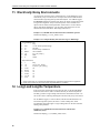
CS547A Conductivity and
Temperature Probe and
A547 Interface
User Manual
Issued 16.11.11
Copyright © 1994-2011 Campbell Scientific Inc.
Printed under licence by Campbell Scientific Ltd.
CSL 421
Guarantee
This equipment is guaranteed against defects in materials and workmanship.
This guarantee applies for twelve months from date of delivery. We will
repair or replace products which prove to be defective during the guarantee
period provided they are returned to us prepaid. The guarantee will not apply
to:
•
Equipment which has been modified or altered in any way without the
written permission of Campbell Scientific
•
Batteries
•
Any product which has been subjected to misuse, neglect, acts of God or
damage in transit.
Campbell Scientific will return guaranteed equipment by surface carrier
prepaid. Campbell Scientific will not reimburse the claimant for costs incurred
in removing and/or reinstalling equipment. This guarantee and the Company’s
obligation thereunder is in lieu of all other guarantees, expressed or implied,
including those of suitability and fitness for a particular purpose. Campbell
Scientific is not liable for consequential damage.
Please inform us before returning equipment and obtain a Repair Reference
Number whether the repair is under guarantee or not. Please state the faults as
clearly as possible, and if the product is out of the guarantee period it should
be accompanied by a purchase order. Quotations for repairs can be given on
request. It is the policy of Campbell Scientific to protect the health of its
employees and provide a safe working environment, in support of this policy a
“Declaration of Hazardous Material and Decontamination” form will be
issued for completion.
When returning equipment, the Repair Reference Number must be clearly
marked on the outside of the package. Complete the “Declaration of
Hazardous Material and Decontamination” form and ensure a completed copy
is returned with your goods. Please note your Repair may not be processed if
you do not include a copy of this form and Campbell Scientific Ltd reserves
the right to return goods at the customers’ expense.
Note that goods sent air freight are subject to Customs clearance fees which
Campbell Scientific will charge to customers. In many cases, these charges are
greater than the cost of the repair.
Campbell Scientific Ltd,
Campbell Park, 80 Hathern Road,
Shepshed, Loughborough, LE12 9GX, UK
Tel: +44 (0) 1509 601141
Fax: +44 (0) 1509 601091
Email: [email protected]
www.campbellsci.co.uk
PLEASE READ FIRST
About this manual
Please note that this manual was originally produced by Campbell Scientific Inc. primarily for the
North American market. Some spellings, weights and measures may reflect this origin.
Some useful conversion factors:
Area: 1 in2 (square inch) = 645 mm2
Length:
1 in. (inch) = 25.4 mm
1 ft (foot) = 304.8 mm
1 yard = 0.914 m
1 mile = 1.609 km
Mass:
1 oz. (ounce) = 28.35 g
1 lb (pound weight) = 0.454 kg
Pressure:
1 psi (lb/in2) = 68.95 mb
Volume:
1 UK pint = 568.3 ml
1 UK gallon = 4.546 litres
1 US gallon = 3.785 litres
In addition, while most of the information in the manual is correct for all countries, certain information
is specific to the North American market and so may not be applicable to European users.
Differences include the U.S standard external power supply details where some information (for
example the AC transformer input voltage) will not be applicable for British/European use. Please
note, however, that when a power supply adapter is ordered it will be suitable for use in your country.
Reference to some radio transmitters, digital cell phones and aerials may also not be applicable
according to your locality.
Some brackets, shields and enclosure options, including wiring, are not sold as standard items in the
European market; in some cases alternatives are offered. Details of the alternatives will be covered in
separate manuals.
Part numbers prefixed with a “#” symbol are special order parts for use with non-EU variants or for
special installations. Please quote the full part number with the # when ordering.
Recycling information
At the end of this product’s life it should not be put in commercial or domestic refuse
but sent for recycling. Any batteries contained within the product or used during the
products life should be removed from the product and also be sent to an appropriate
recycling facility.
Campbell Scientific Ltd can advise on the recycling of the equipment and in some cases
arrange collection and the correct disposal of it, although charges may apply for some
items or territories.
For further advice or support, please contact Campbell Scientific Ltd, or your local agent.
Campbell Scientific Ltd, Campbell Park, 80 Hathern Road, Shepshed, Loughborough, LE12 9GX, UK
Tel: +44 (0) 1509 601141 Fax: +44 (0) 1509 601091
Email: [email protected]
www.campbellsci.co.uk
Contents
PDF viewers note: These page numbers refer to the printed version of this document. Use
the Adobe Acrobat® bookmarks tab for links to specific sections.
1. Overview....................................................................... 1
1.1 EC Sensor .................................................................................................1
1.2 A547 Interface ..........................................................................................1
2. Specifications .............................................................. 2
2.1 CS547A Probe ..........................................................................................2
2.2 A547 Interface ..........................................................................................2
2.3 Temperature Sensor ..................................................................................3
3. Installation.................................................................... 3
3.1 Site Selection ............................................................................................3
3.2 Mounting ..................................................................................................3
4. Wiring ........................................................................... 3
5. Programming ............................................................... 4
5.1 Programming Overview............................................................................4
5.1.1 Measurement Programming – CRBasic Example Code .................5
5.1.2 Measurement Programming – Edlog Program Example.................7
6. Calibration.................................................................. 11
6.1
6.2
6.3
6.4
Conversion Factors .................................................................................11
Typical Ranges .......................................................................................11
Factory Calibration .................................................................................11
Field Calibration .....................................................................................11
6.4.1 CRBasic Program Example ..........................................................12
6.4.2 Edlog Program Example ...............................................................12
7. Maintenance............................................................... 14
8. Analysis of Errors...................................................... 14
8.1 EC Measurement Error ...........................................................................14
8.2 Temperature Measurement Error............................................................15
9. Deriving a Temperature Compensation
Coefficient ................................................................ 16
10. Therm107 / P11 Instruction Details........................ 16
11. Electrically Noisy Environments............................ 18
i
12. Long Lead Lengths Temperature........................... 18
13. CS547A Schematic .................................................. 19
Figures
1-1. A547 Interface and CS547A Conductivity and Temperature Probe .......2
4-1. CS547A Wiring Diagram for Example Below........................................4
8.1-1. Plot of Ideal and Actual Correction between 0 and 0.44 mS cm-1 .....14
8.1-2. Plot of Ideal and Actual Correction between 0.44 and 7.0 mS cm-1 ..15
8.2-1. Error Produced by Polynomial Fit to Published Values.....................16
13-1. CS547A Conductivity and Temperature Circuit Diagram ..................19
13-2. A547 Interface Circuit Diagram..........................................................20
Tables
8.2-1. Thermistor Interchangeability Specification Temperature.................15
8.2-2. Polynomial Error ................................................................................15
10-1. Temperature, Resistance and Datalogger Output................................17
10-2. Polynomial Coefficients ......................................................................17
ii
CS547A Conductivity and Temperature
Probe and A547 Interface
1. Overview
The CS547A conductivity and temperature probe, and A547 interface are designed
for measuring the electrical conductivity, dissolved solids, and temperature of
fresh water with Campbell Scientific dataloggers. This sensor can be used with
any CSI logger that can issue an AC excitation. This includes most new CRBasic
dataloggers as well as older, Edlog loggers. Exceptions include the CR200-series,
the BDR301 and BDR320 loggers which did not have this feature. Use with our
AM16/32(B) multiplexer is possible when needing to measure several of these
probes on one datalogger.
Electrical conductivity (EC) of a solution is a simple physical property, but
measurements can be difficult to interpret. This manual instructs the user how to
make EC measurements with the CS547A. Accuracy specifications apply to
measurements of EC in water containing KCl, Na2SO4, NaHCO3, and/or NaCl,
which are typical calibration compounds, and to EC not yet compensated for
temperature effects.
Statements made on methods of temperature compensation or estimating dissolved
solids are included to introduce common ways of refining and interpreting data, but
are not definitive. Authoritative sources to consult include the USGS Water-Supply
Paper 1473, The pH and Conductivity Handbook published by OMEGA
Engineering, physical chemistry texts, and other sources.
1.1 EC Sensor
The EC sensor consists of three stainless steel rings mounted in an epoxy tube as
shown in Figure 4-1. Resistance of water in the tube is measured by excitation
of the centre electrode with positive and negative voltage.
This electrode configuration eliminates the ground looping problems associated
with sensors in electrical contact with earth ground.
Temperature is measured with a thermistor in a three wire half bridge
configuration.
1.2 A547 Interface
The interface contains the completion resistors and blocking capacitors. The
interface should be kept in a non-condensing environment that is maintained
within the temperature range of the unit.
1
CS547A Conductivity and Temperature Probe and A547 Interface
Figure 1-1. A547 Interface and CS547A Conductivity and Temperature Probe
2. Specifications
2.1 CS547A Probe
Construction
The probe housing is epoxy
Size — L x W x H
89 mm (3.5 inches) x 25.4 mm (1 inch) x 19 mm (0.75
inch)
Maximum Cable
Length
305 m (1000 ft). The sensor must be ordered with desired
length as cable cannot be added to existing probes.
Depth Rating
Maximum 305 m (1000 ft)
pH Range
Solution pH of less than 3.0 or greater than 9.0 may damage
the stainless steel housing.
Electrodes
Passivated 316 SS with DC isolation capacitors.
Cell Constant
Individually calibrated. The cell constant (Kc) is found on
a label near the termination of the cable.
Temp. Range of Use
0° to 50°C.
EC Range
Approx. 0.005 to 7.0 mS cm-1.
Accuracy
in KCl and Na2SO4, NaHCO3, and NaCl standards at 25°C:
±5% of reading 0.44 to 7.0 mS cm-1.
±10% of reading 0.005 to 0.44 mS cm-1.
2.2 A547 Interface
2
Size
Dimensions: 64 mm (2.5”) x 46 mm (1.8”) x 23 mm (0.9”)
Weight: 45 g (2 oz)
Temperature Rating
-15°C to +50°C
User Manual
2.3 Temperature Sensor
Thermistor
Betatherm 100K6A1.
Range
0°C to 50°C.
Accuracy
Error ±0.4°C (See Section 8.2).
3. Installation
CAUTION
Rapid heating and cooling of the probe, such as leaving it in
the sun and then submersing it in a cold stream, may cause
irreparable damage.
3.1 Site Selection
The EC sensor measures the EC of water inside the hole running through the
sensor, so detection of rapid changes in EC requires that the probe be flushed
continuously. This is easy to accommodate in a flowing stream by simply
orienting the sensor parallel to the direction of flow. In stilling wells and ground
wells, however, diffusion rate of ions limits the response time.
3.2 Mounting
The housing and sensor cable are made of water impervious, durable materials.
Care should be taken, however, to mount the probe where contact with abrasives
and moving objects will be avoided. Strain on cables can be minimized by using
a split mesh strain relief sleeve on the cable, which is recommended for cables
over 100 ft. The strain relief sleeve is available from Campbell Scientific as part
number 7421.
Because the CS547A has a slightly positive buoyancy, we recommend securing
the sensor to a fixed or retractable object or selecting the cable weight option.
The A547 is usually mounted in the datalogger enclosure.
4. Wiring
WARNING
The excitation channel used for each EC measurement
must be separate from the one used for temperature or
measurement errors will result.
If multiple
CS547A/A547s are to be wired to a single logger, each
conductivity excitation must be kept on a separate,
dedicated EX channel, but you can combine several
temperature excitations lines onto a single EX port. (On
newer loggers, these are labelled as Vx.)
3
CS547A Conductivity and Temperature Probe and A547 Interface
AG
AG
SE TEMP
EX2
EX TEMP
EX1
EX COND
1H
HI COND
1L
LO COND
Ground
DATALOGGER
SE3
SHIELD
Clear (Shield)
SHIELD
Red (Temp)
TEMP
SENSOR
COND
Orange (Cond)
Black (Ex Cond)
EX COND
Green (Ex Temp)
EX TEMP
Figure 4-1. CS547A Wiring Diagram for Example Below
5. Programming
All example programs may require modification by the user to fit the specific
application's wiring and programming needs. All program examples in this
manual are for the CR10(X) or CR1000 and assume that datalogger is wired to
the A547 interface are as follows: the LO COND lead is connected to 1L, the
HI COND to 1H, the EX COND to EX1, the EX TEMP to EX2, and the SE
TEMP to SE3.
Public Variable Declarations / Input Location Labels
Definitions for the following program:
Rs
Solution resistance
Rp
Resistance of leads/cable and blocking caps
Ct
Solution EC with no temp. correction
Temp_degC
Solution temperature in °C
C25mScm_1 EC corrected for temperature
5.1 Programming Overview
Typical datalogger programs to measure the CS547A consist of four parts:
1.
Measurement of EC and temperature
EC: Resistance across the electrodes is computed from the results of the
BrFull (P6) or BrHalf (P5) instructions (chosen automatically as part of
the autoranging feature) followed by the Bridge Transformation algorithm
(P59).
2.
Correction of ionization errors in EC measurements
Ionization caused by the excitation of the EC sensor can cause large errors.
Campbell Scientific has developed a linear correction for conductivity
between 0.005 and 0.44 mS cm-1, and a quadratic correction for
conductivity between 0.44 and 7.0 mS cm-1. Corrections were determined
in standard salt solutions containing KCl, Na2SO4, NaHCO3, and NaCl.
4
User Manual
3.
Correction of temperature errors in EC measurements
The effect of temperature on the sample solution can cause large errors in
the EC measurement. A simple method of correcting for this effect is to
assume a linear relationship between temperature and EC. This method
generally produces values to within 2% to 3% of a measurement made at
25°C.
The best corrections are made when the temperature coefficient is
determined at a temperature near field conditions. See Section 9 for details
on how to determine the temperature coefficient. If determining the
temperature coefficient is not possible, use a value of 2%/°C as a rough
estimate.
4.
Output processing
Over large ranges, EC is not linear and is best reported as samples using
instruction P70. In limited ranges, averaging (P71) measurements over
time may be acceptable. Convention requires that the temperature at the
time of the measurement be reported.
5.1.1 Measurement Programming - CRBasic Example Code
'Program name: CS547A.CR1
'\\\\\\\\\\\\\\\\\\\\\\\\\ DECLARATIONS /////////////////////////
Public Rp, CellConstant, TempCoef
Public Rs, Ct
Public TempDeg_C
Public C25mScm_1
Dim OneOvrRs, Ct100, A, TC_Proces
'\\\\\\\\\\\\\\\\\\\\\\\\ OUTPUT SECTION ////////////////////////
DataTable (ECSample,True,-1)
DataInterval (0,60,Min,10)
Sample (1,Ct,FP2)
Sample (1,TempDeg_C,FP2)
Sample (1,C25mScm_1,FP2)
EndTable
'\\\\\\\\\\\\\\\\\\\\\\\\\\\ PROGRAM ////////////////////////////
BeginProg
'evaluate and edit each of these 3 user specific values
Rp=25
'edit this value to the actual footage of cable on your sensor
CellConstant=1.50
'edit this value with the Cell Constant (Kc) printed
'on the label of each sensor
TempCoef=2
'see section 9 of the manual for an explanation of how
'to more precisely determine the value of this coefficient
Scan(5,Sec, 3, 0)
'make a preliminary measurement of resistance to determine best range code
BrFull(Rs, 1, mV2500, 1, VX1, 1, 2500, True, True, 0, 250, -0.001, 1)
Rs = 1*(Rs/(1.0-Rs))
'test the initial measurement to then make a more accurate measurement
Select Case Rs
Case Is < 1.8
BRHalf(Rs, 1, mV2500, 2, VX1, 1, 2500, True, 0, 250, 1, 0)
Rs =(Rs/(1-Rs))
5
CS547A Conductivity and Temperature Probe and A547 Interface
Case Is < 9.25
BRFull(Rs, 1, mV2500, 1, VX1, 1, 2500, True, True, 0, 250, -0.001, 1)
Rs =(Rs/(1-Rs))
Case Is < 280
BRFull(Rs, 1, mV250, 1, VX1, 1, 2500, True, True, 0, 250, -0.001, 1)
Rs = (Rs/(1-Rs))
EndSelect
'Subtract resistance errors (Rp) caused by the blocking capacitors
'(0.005Kohm and the cable length(0.000032Kohm/ft)
Rp = (Rp* -0.000032)-0.005
Rs = Rs + Rp
'EC is then calculated by multiplying the reciprocal of the resistance,
'which is conductance, by the cell constant
OneOvrRs = 1 / Rs
Ct = OneOvrRs * CellConstant
'the following corrects for errors of ionization in the EC measurement
If (Ct < 0.474) Then
Ct = (Ct * 0.9503) - 0.0038
Else
Ct=-0.0289+0.9861*Ct+0.0285*Ct^2
EndIf
'correct errors in the EC measurement due to temperature
Therm107(TempDeg_C,1,3,Vx2,0,_50Hz,1,0)
A = TempDeg_C + -25
Ct100 = Ct * 100
TC_Proces = A * TempCoef
TC_Proces = TC_Proces + 100
C25mScm_1 = Ct100 / TC_Proces
'end scan loop by calling output table
CallTable ECSample
NextScan
EndProg
6
User Manual
5.1.2 Measurement Programming - Edlog Dataloggers
*Table 1 Program
01: 5
Execution Interval (seconds)
;Make a preliminary measurement of resistance for autoranging.
1: Full Bridge (P6)
1: 1
Reps
2: 15
±2500 mV Fast Range
3: 1
DIFF Channel
4: 1
Excite all reps w/Exchan 1
5: 2500
mV Excitation
6: 1
Loc [ Rs
]
7: -.001
Mult
8: 1
Offset
2: BR Transform Rf [X/(1-X)] (P59)
1: 1
Reps
2: 1
Loc [ Rs
]
3: 1
Multiplier (Rf)
;
;Test the initial measurement to make a more accurate measurement.
;
3: CASE (P93)
1: 1
Case Loc [ Rs
]
4: If Case Location < F (P83)
1: 1.8
F
2: 30
Then Do
5: AC Half Bridge (P5)
1: 1
Reps
2: 15
±2500 mV Fast Range
3: 2
SE Channel
4: 1
Excite all reps w/Exchan 1
5: 2500
mV Excitation
6: 1
Loc [ Rs
]
7: 1.0
Mult
8: 0.0
Offset
6: BR Transform Rf[X/(1-X)] (P59)
1: 1
Reps
2: 1
Loc [ Rs
]
3: 1
Multiplier (Rf)
7: End (P95)
8: If Case Location < F (P83)
1: 9.25
F
2: 30
Then Do
9: Full Bridge (P6)
1: 1
2: 15
3: 1
4: 1
5: 2500
Reps
±2500 mV Fast Range
DIFF Channel
Excite all reps w/Exchan 1
mV Excitation
7
CS547A Conductivity and Temperature Probe and A547 Interface
6:
7:
8:
1
-.001
1
Loc [ Rs
Mult
Offset
]
10: BR Transform Rf[X/(1-X)] (P59)
1: 1
Reps
2: 1
Loc [ Rs
]
3: 1
Multiplier (Rf)
11: End (P95)
12: If Case Location < F (P83)
1:280
F
2:30
Then Do
13: Full Bridge (P6)
1: 1
Reps
2: 14
±250 mV Fast Range
3: 1
DIFF Channel
4: 1
Excite all reps w/Exchan 1
5: 2500
mV Excitation
6: 1
Loc [ Rs
]
7: -.001
Mult
8: 1
Offset
14: BR Transform Rf[X/(1-X)] (P59)
1: 1
Reps
2: 1
Loc [ Rs
]
3: 1
Multiplier (Rf)
15: End (P95)
16: End (P95)
;
;Subtract resistance errors (Rp) caused by the blocking capacitors
;(0.005Kohm) and the cable length (0.000032kohm/ft). Enter cable lead
;length in nnn below.
;
17: Z=F (P30)
1: nnn
2: 00
3: 5
F
Exponent of 10
Z Loc [ Rp
]
18: Z=X*F (P37)
1: 5
X Loc [ Rp
2: .00032
F
3: 5
Z Loc [ Rp
19: Z=X*F (P37)
1: 5
X Loc [ Rp
2: -.1
F
3: 5
Z Loc [ Rp
20: Z=X+F (P34)
1: 5
X Loc [ Rp
2: -.005
F
3: 5
Z Loc [ Rp
8
]
]
]
]
]
]
Enter cable length in feet.
User Manual
21: Z=X+Y (P33)
1: 1
X Loc [ Rs
2: 5
Y Loc [ Rp
3: 1
Z Loc [ Rs
]
]
]
;EC is then calculated by multiplying the reciprocal of resistance,
;which is conductance, by the cell constant.
NOTE: The cell constant (Kc) is printed on the label of each sensor or it can be calculated (see
Section 6.4). It is entered in place of nnn below.
22: Z=1/X (P42)
1: 1
2: 2
X Loc [ Rs
]
Z Loc [ one_ovrRs ]
23: Z=X*F (P37)
1: 2
X Loc [ one_ovrRs ]
2: nnn
F
3: 3
Z Loc [ Ct
]
Enter cell constant.
24: Temp (107) (P11)
1: 1
Reps
2: 3
SE Channel
3: 2
Excite all reps w/E2
4: 4
Loc [ Temp_degC ]
5: 1.0
Mult
6: 0.0
Offset
;
;The following program set corrects for errors of ionization in the EC
;measurement.
;
25: IF (X<=>F) (P89)
1: 3
X Loc [ Ct
2: 4
<
3: .474
F
4: 30
Then Do
26: Z=X*F (P37)
1: 3 X Loc [ Ct
2: .95031
3: 3 Z Loc [ Ct
27: Z=X+F (P34)
1: 3 X Loc [ Ct
2: -.00378
3: 3 Z Loc [ Ct
]
]
F
]
]
F
]
28: Else (P94)
29: Polynomial (P55)
1: 1
Reps
2: 3
X Loc [ Ct
]
3: 3
F(X) Loc [ Ct
]
4: -.02889
C0
5: .98614
C1
6: .02846
C2
9
CS547A Conductivity and Temperature Probe and A547 Interface
7:
8:
9:
.000000
.000000
.000000
C3
C4
C5
30: End (P95)
;This next program set will correct errors in the EC measurement resulting
;from temperature differences.
;
31: Z=X+F (P34)
1: 4
X Loc [ Temp_degC ]
2: -25
F
3: 6
Z Loc [ A
]
32: Z=X*F (P37)
1: 3
X Loc [ Ct
]
2: 100
F
3: 7
Z Loc [ Ct100 ]
33: Z=X*F (P37)
1: 6
X Loc [ A
2: nnn
F
3: 8Z Loc [ TC_Proces ]
]
Enter TC (%/°C) to correct cond. reading.
34: Z=X+F (P34)
1: 8
X Loc [ TC_Proces ]
2: 100
F
3: 8
Z Loc [ TC_Proces ]
35: Z=X/Y (P38)
1: 7
X Loc [ Ct100 ]
2: 8
Y Loc [ TC_Proces ]
3: 9
Z Loc [ C25mScm_l ]
EC corrected for temperature.
;Output processing, convention states that the temperature be reported
;with the EC measurement.
;
36: Do (P86)
1: 10
Set Output Flag High (Flag 0)
37: Sample (P70)
1: 1
Reps
2: 3
Loc [ Ct
]
38: Sample (P70)
1: 1
Reps
2: 4
Loc [ Temp_degC ]
39: Sample (P70)
1: 1
Reps
2: 9
Loc [ C25mScm_l ]
*Table 2 Program
02: 0.0
Execution Interval (seconds)
*Table 3 Subroutines
End Program
10
User Manual
6. Calibration
6.1 Conversion Factors
1 S (Siemens) = 1 mho = 1/ohm
Although mS·cm-1 and µS·cm-1 are the commonly used units of EC, the SI base
unit is S·m-1. The result of the example programs is mS·cm-1
EC measurements can be used to estimate dissolved solids. For high accuracy,
calibration to the specific stream is required. However, for rough estimates,
values between 550 and 750 mg·l-1 / mS·cm-1 are typical with the higher values
generally being associated with waters high in sulphate concentration (USGS
Water-Supply Paper #1473, p. 99). A common practice is to multiply the EC in
mS·cm-1 by 500 to produce ppm or mg·l-1.
6.2 Typical Ranges
Single distilled water will have an EC of at least 0.001 mS·cm-1. ECs of melted
snow usually range from 0.002 to 0.042 mS·cm-1. ECs of stream water usually
range from 0.05 to 50.0 mS·cm-1, the higher value being close to the EC of sea
water (USGS Water-Supply Paper 1473, p. 102).
6.3 Factory Calibration
The CS547A is shipped with a cell constant calibrated in a 0.01 molal KCl
solution at 25.0°C ±0.05°C. The solution has an EC of 1.408 mS cm-1.
6.4 Field Calibration
The cell constant is a dimensional number expressed in units of cm-1. The unit
cm-1 is slightly easier to understand when expressed as cm·cm-2. Because it is
dimensional, the cell constant as determined at any one standard, will change
only if the physical dimensions inside the CS547A probe change. Error due to
thermal expansion and contraction is negligible. Corrosion and abrasion,
however, have the potential of causing significant errors.
A field calibration of the CS547A cell constant can be accomplished as follows:
1.
Make a 0.01 molal KCL solution by dissolving 0.7456 g of reagent grade
KCl in 1000 g of distilled water, or purchase a calibration solution.
2.
Clean the probe thoroughly with the black nylon brush shipped with the
CS547A and a small amount of soapy water. Rinse thoroughly with
distilled water, dry thoroughly, and place in the KCl solution.
3.
Connect the CS547A and A547 or probe and interface to the datalogger
using the wiring described in Section 4. Enter the following program into
the datalogger.
The calibration solution temperature must be between 1°C and 35°C; the
polynomial in step 11 (P58) corrects for temperature errors within this range.
The solution constant of 1.408 mS cm-1 (for prepared solution mentioned
above), entered in step 13 (P37), is valid only for a 0.01 molal KCl solution.
Location 8 [Kc (cm-1)], generated by step 14, will contain the resultant cell
constant.
11
CS547A Conductivity and Temperature Probe and A547 Interface
6.4.1 CRBasic Program Example
'CR1000 Datalogger
'Field Calibration program to determine new Cell Constant (Kc) for CS547A conductivity probe
Public Rs, Rp, T
Dim T_25, f_of_T
Public Conductivity, Kc
Const CalSolution = 1.408
'for 0.01 molal KCL solution
'Data Table not required for Field Calibration – monitor “Kc” in Public table
'Main Program
BeginProg
'edit cable length (Rp) to reflect footage of actual lead length
Rp = 25 'feet
Scan (10,Sec,0,0)
BrHalf(Rs, 1, mV2500, 2, VX1, 1, 2500, True, 0, 250, 1, 0)
Rs =(Rs/(1-Rs))
'correct for resistance of cabling
Rs = Rs + (((Rp*.00032)* -0.1) - 0.005)
'compensate for temperature effects
Therm107 (T,1,3,Vx2,0,_50Hz,1.0,0)
T_25 = (T-25) * 0.01
f_of_T = 0.99124 - (1.8817*T_25) + (3.4789*T_25^2) - (3.51*T_25^3) - (1.2*T_25^4)
- (43*T_25^5)
Conductivity = (1/f_of_T)*CalSolution
Kc = Conductivity * Rs
NextScan
EndProg
6.4.2 Edlog Program Example
1: AC Half Bridge (P5)
1: 1
Rep
2: 15
2500 mV fast Range (5000 mV fast for 21X)
3: 2
IN Chan
4: 1
Excite all reps w/EXchan 1
5: 2500
mV Excitation (5000 mV for 21X)
6: 1
Loc [Rs
]
7: 1
Mult
8: 0
Offset
2: BR Transform Rf[X/(1-X)] (P59)
1: 1
Rep
2: 1
Loc [Rs
]
3: 1
Multiplier (Rf)
12
3: Z=F (P30)
1: nnn
2: 00
3: 5
F
Exponent of 10
Loc [Rp
]
4: Z=X*F (P37)
1: 5
2: .00032
3: 5
Loc [Rp
F
Loc [Rp
]
5: Z=X*F (P37)
1: 5
2: -.1
3: 5
Loc [Rp
F
Loc [Rp
]
]
]
Enter Cable Length in Feet
User Manual
6: Z=X+F (P34)
1: 5
2: -.005
3: 5
7: Z=X+Y (P33)
1: 1
2: 5
3: 1
Loc [Rp
]
Loc [Rp
]
X Loc [Rs
Y Loc [Rp
Z Loc [Rs
]
]
]
8: Temp 107 Probe (P11)
1: 1
Rep
2: 3
IN Chan
3: 2
Excite all reps w/EXchan 2
4: 2
Loc [t
]
5: 1
Mult
6: 0
Offset
9: Z=X+F (P34)
1: 2
2: -25
3: 3
X Loc [t
]
F
Z Loc [T25_01]
10: Z=X*F (P37)
1: 3
X Loc [T25_01]
2: .01
F
3: 3
Z Loc [T25_01]
11: Polynomial (P55)
1: 1
Rep
2: 3
X Loc [T25_01]
3: 4
F(X) Loc [f_of_T
4: .99124
C0
5: -1.8817
C1
6: 3.4789
C2
7: -3.51
C3
8: -1.2
C4
9: -43
C5
12: Z=1/X (P42)
1: 4
2: 6
]
X Loc [f_of_T
]
Z Loc [one_ovrfT ]
13: Z=X*F (P37)
1: 6
X Loc [one_ovrfT
2: 1.408
F
3: 7
Z Loc [Conductiv]
]
EC of calibration solution
14: Z=X*Y (P36)
1: 7
X Loc [Conductiv]
2: 1
Y Loc [Rs
]
3: 8
Z Loc [Kc
]
End
13
CS547A Conductivity and Temperature Probe and A547 Interface
7. Maintenance
Routine maintenance includes thoroughly cleaning the orifice of the CS547A
probe with the black nylon brush provided and a little soapy water. Rinse
thoroughly.
8. Analysis of Errors
8.1 EC Measurement Error
1.
Bridge Measurement Error: < 1.0%
2.
Calibration Error:
bridge measurement: < 0.5%
calibration solution: < 1.0%
3.
Ionization Error of KCl and Na+ Solutions After Correction:
< 2.0%, 0.45 to 7.0 mS cm-1
< 8.0%, 0.005 to 0.45 mS cm-1
Correction of Ionization Errors: Figures 8.1-1 and 8.1-2 show the amount of
correction applied by the example program to compensate for ionization effects
on the measurements. Also shown is an ideal correction. Factors were derived
by measuring the standard solutions described in Section 2.2 with values of
0.0234, 0.07, 0.4471, 07, 1.413, 2.070, 3.920, and 7.0 mS cm-1.
Figure 8.1-1. Plot of Ideal and Actual Correction
between 0 and 0.44 mS cm-1
14
User Manual
Figure 8.1-2. Plot of Ideal and Actual Correction
between 0.44 and 7.0 mS cm-1
8.2 Temperature Measurement Error
The overall probe accuracy is a combination of the thermistor's
interchangeability specification, the precision of the bridge resistors, and the
polynomial error. In a "worst case" all errors add to an accuracy of ±0.4°C over
the range of -24° to 48°C and ±0.9°C over the range of -38°C to 53°C. The
major error component is the interchangeability specification of the thermistor,
tabulated in Table 8.2-1. For the range of 0° to 50°C the interchangeability error
is predominantly offset and can be determined with a single point calibration.
Compensation can then be done with an offset entered in the measurement
instruction. The bridge resistors are 0.1% tolerance with a 10 ppm temperature
coefficient. Polynomial errors are tabulated in Table 8.2-2 and plotted in Figure
8.2-1.
Table 8.2-1. Thermistor
Interchangeability Specification
Temperature
Temperature (°C)
Tolerance (±°C)
−40
0.40
−30
0.40
−20
0.32
−10
0.25
0 to +50
0.20
Table 8.2-2. Polynomial Error
-40 to +56
<±1.0°C
-38 to +53
<±0.5°C
-24 to +48
<±0.1°C
15
CS547A Conductivity and Temperature Probe and A547 Interface
Figure 8.2-1. Error Produced by Polynomial Fit to Published Values
9. Deriving a Temperature Compensation Coefficient
1.
Place the CS547A in a sample of the solution to be measured. Bring the
sample and the probe to 25°C.
2.
Enter the example program from Section 5.2 in the datalogger and record Ct
at 25°C from Location 3. This number will be C25 in the formula in Step 4.
3.
Bring the solution and the probe to a temperature (t) near the temperature at
which field measurements will be made. This temperature will be t (in °C)
in the formula. Record Ct at the new temperature from Location 3. This
number will be C in the formula in Step 4.
4.
Calculate the temperature coefficient (TC) using the following formula.
TC = 100∗
( C − C 25 )
= %/ ° C
( t − 25)∗ C 25
Enter TC in the appropriate location (nnn) as shown in the program segment in
Section 5.2 .
10. Therm107 / P11 Instruction Details
Understanding the details in this section is not necessary for general operation of
the CS547A probe with CSI's dataloggers.
The Therm107 instruction (or P11 in Edlog) outputs a precise 2 VAC excitation
(4 V with the 21X) and measures the voltage drop due to the sensor resistance.
The thermistor resistance changes with temperature. The instruction calculates
the ratio of voltage measured to excitation voltage (Vs/Vx) which is related to
resistance, as shown below:
Vs/Vx
= 1000/(Rs+249000+1000)
where Rs is the resistance of the thermistor.
16
User Manual
See the measurement section of the datalogger manual for more information on
bridge measurements.
Temperature is calculated using a fifth order polynomial equation correlating
Vs/Vx with temperature. The polynomial coefficients are given in Table 10-2.
The polynomial input is (Vs/Vx)*800. Resistance and datalogger output at
several temperatures are shown in Table 10-1.
Table 10-1. Temperature , Resistance, and
Datalogger Output
0.00
2.00
4.00
6.00
8.00
10.00
12.00
14.00
16.00
18.00
20.00
22.00
24.00
26.00
28.00
30.00
32.00
34.00
36.00
38.00
40.00
42.00
44.00
46.00
48.00
50.00
52.00
54.00
56.00
58.00
60.00
351017
315288
283558
255337
230210
207807
187803
169924
153923
139588
126729
115179
104796
95449
87026
79428
72567
66365
60752
55668
51058
46873
43071
39613
36465
33598
30983
28595
26413
24419
22593
-0.06
1.96
3.99
6.02
8.04
10.06
12.07
14.06
16.05
18.02
19.99
21.97
23.95
25.94
27.93
29.95
31.97
33.99
36.02
38.05
40.07
42.07
44.05
46.00
47.91
49.77
51.59
53.35
55.05
56.70
58.28
Table 10-2. Polynomial
Coefficients
COEFFICIENT
VALUE
C0
C1
C2
C3
C4
C5
-53.4601
9.08067
-8.32569 x 10-01
5.22829 x 10-02
-1.67234 x 10-03
2.21098 x 10-05
17
CS547A Conductivity and Temperature Probe and A547 Interface
11. Electrically Noisy Environments
AC power lines can be the source of electrical noise. If the datalogger is in an
electronically noisy environment, the 107 temperature measurement should be
measured with longer integration periods than 250µSec. For CRBasic loggers,
the Therm107 Integration parameter has options for 60 Hz rejection that impose
a long 3mSec integration. Sixty and 50 Hz rejection is also available as an
option in the Excitation Channel parameter of Instruction 11 for the CR10X,
CR510, and CR23X dataloggers. For the CR10, CR21X and CR7, the 107
should be measured with the AC half bridge (Instruction 5).
Example 11-1, CR1000 measurement instruction with 60 Hz rejection:
Therm107(TempDeg_C,1,3,2,0,_60Hz,1.0,0.0)
Example 11-2. Sample CR10(X) Instructions Using AC Half Bridge
1: AC Half Bridge (P5)
1: 1
Rep
2: 22**
7.5 mV 60 Hz rejection Range
3: 3*
IN Chan
4: 2*
Excite all reps w/EXchan 2
5: 2000**
mV Excitation
6: 11*
Loc [ Air_Temp ]
7: 800
Mult
8: 0
Offset
2: Polynomial (P55)
1: 1
Rep
2: 11*
X Loc [ Air_Temp ]
3: 11*
F(X) Loc [ Air_Temp ]
4: -53.46
C0
5: 90.807
C1
6: -83.257
C2
7: 52.283
C3
8: -16.723
C4
9: 2.211
C5
* Proper entries will vary with program and datalogger channel and input location assignments.
** On the 21X and CR7 use the 15 mV input range and 4000 mV excitation.
12. Long Lead Lengths Temperature
If the CS547A has lead lengths of more than 300 feet, use the DC Half Bridge
instruction (Instruction 4) with a 2 millisecond delay to measure temperature.
The delay provides a longer settling time before the measurement is made. Do
not use the CS547A with long lead lengths in an electrically noisy environment.
For all CRBasic loggers, as well as CR10X, CR510 and CR23X that have 60
and 50 Hz integration options, this forces a 3 mSec settling time, which
accommodates long lead lengths. Longer settling times can be entered into the
Settling Time parameter
Example 12-1. CR1000 measurement instruction with 20 mSec
(20000 uSec) delay:
Therm107(TempDeg_C,1,3,2,20000,_60Hz,1.0,0.0)
18
User Manual
Example 12-2. Sample Program CR10 Using DC Half Bridge with Delay
1: Excite, Delay,Volt(SE) (P4)
1: 1
Rep
2: 2**
7.5 mV slow range
3: 3*
IN Chan
4: 2*
Excite all reps w/EXchan 2
5: 2
Delay (units .01sec)
6: 2000**
mV Excitation
7: 11*
Loc [ Temp_C ]
8: .4***
Mult
9: 0
Offset
2: Polynomial (P55)
1: 1
Rep
2: 11*
X Loc Temp_C
3: 11*
F(X) Loc [ Temp_C ]
4: -53.46
C0
5: 90.807
C1
6: -83.257
C2
7: 52.283
C3
8: -16.723
C4
9: 2.211
C5
*
Proper entries will vary with program and datalogger channel and input location assignments.
** On the 21X and CR7 use the 15 mV input range and 4000 mV excitation.
*** Use a multiplier of 0.2 with a 21X and CR7.
13. CS547A Schematic
Black (Ex Cond)
Green (Ex Temp)
Red (Temp)
Orange (Cond)
Figure 13-1. CS547A Conductivity and Temperature Circuit Diagram
19
CS547A Conductivity and Temperature Probe and A547 Interface
Datalogger
Connections
EX COND
HI COND
LO COND
AG
Sensor
Connections
1K
R2
220µFD
+
220µFD
+
1K
220µFD
+
220µFD
+
EX TEMP
EX COND
COND
R1
SE TEMP
TEMP
EX TEMP
SHIELD
SHIELD
Figure 13-2. A547 Interface Circuit Diagram
20
CAMPBELL SCIENTIFIC COMPANIES
Campbell Scientific, Inc. (CSI)
815 West 1800 North
Logan, Utah 84321
UNITED STATES
www.campbellsci.com • [email protected]
Campbell Scientific Africa Pty. Ltd. (CSAf)
PO Box 2450
Somerset West 7129
SOUTH AFRICA
www.csafrica.co.za • [email protected]
Campbell Scientific Australia Pty. Ltd. (CSA)
PO Box 444
Thuringowa Central
QLD 4812 AUSTRALIA
www.campbellsci.com.au • [email protected]
Campbell Scientific do Brazil Ltda. (CSB)
Rua Luisa Crapsi Orsi, 15 Butantã
CEP: 005543-000 São Paulo SP BRAZIL
www.campbellsci.com.br • [email protected]
Campbell Scientific Canada Corp. (CSC)
11564 - 149th Street NW
Edmonton, Alberta T5M 1W7
CANADA
www.campbellsci.ca • [email protected]
Campbell Scientific Centro Caribe S.A. (CSCC)
300N Cementerio, Edificio Breller
Santo Domingo, Heredia 40305
COSTA RICA
www.campbellsci.cc • [email protected]
Campbell Scientific Ltd. (CSL)
Campbell Park
80 Hathern Road
Shepshed, Loughborough LE12 9GX
UNITED KINGDOM
www.campbellsci.co.uk • [email protected]
Campbell Scientific Ltd. (France)
3 Avenue de la Division Leclerc
92160 ANTONY
FRANCE
www.campbellsci.fr • [email protected]
Campbell Scientific Spain, S. L.
Avda. Pompeu Fabra 7-9
Local 1 - 08024 BARCELONA
SPAIN
www.campbellsci.es • [email protected]
Campbell Scientific Ltd. (Germany)
Fahrenheitstrasse13, D-28359 Bremen
GERMANY
www.campbellsci.de • [email protected]
Please visit www.campbellsci.com to obtain contact information for your local US or International representative.