1
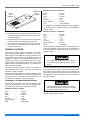
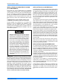
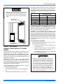
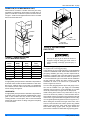
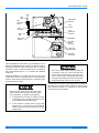
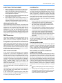
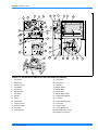
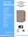
INSTALLATION
INSTRUCTIONS
ALL POSITION
AUTOMATIC IGNITION FURNACES
G8C / FG8 SERIES MODELS
50 - 125 MBH INPUT
UPFLOW / HORIZONTAL
AUTOMATIC IGNITION FURNACES
TABLE OF CONTENTS
G8C / FG8 SERIES MODELS
150 MBH INPUT
GENERAL INFORMATION . . . . . . . . . . . . . . . . . . . . . . . 2
FURNACE SPECIFICATIONS . . . . . . . . . . . . . . . . . . . . 3
PRE-INSTALLATION INSPECTION . . . . . . . . . . . . . . . . 4
CODE COMPLIANCE . . . . . . . . . . . . . . . . . . . . . . . . . . . 4
INSTALLATION POSITION
(50-125 MBH Models) . . . . . . . . . . . . . . . . . . . . . . . . . . . 4
INSTALLATION POSITION
(150 MBH Models) . . . . . . . . . . . . . . . . . . . . . . . . . . . . . 4
CONVERSION INFORMATION
(50-125 MBH Models) . . . . . . . . . . . . . . . . . . . . . . . . . . . 4
TO CONVERT FROM DOWNFLOW TO UPFLOW
CONFIGURATION (50-125 MBH Models) . . . . . . . . . . . 4
TO CONVERT FROM UPFLOW TO DOWNFLOW
CONFIGURATION (50-125 MBH Models) . . . . . . . . . . . 5
FURNACE LOCATION . . . . . . . . . . . . . . . . . . . . . . . . . . 6
COMBUSTION AND VENTILATION AIR . . . . . . . . . . . . 7
FURNACE SIZING AND DUCT
SYSTEM DESIGN . . . . . . . . . . . . . . . . . . . . . . . . . . . . . . 8
RETURN AIR AND FILTERS . . . . . . . . . . . . . . . . . . . . . 9
GAS PIPING . . . . . . . . . . . . . . . . . . . . . . . . . . . . . . . . . 10
VENTING (CATEGORY I) . . . . . . . . . . . . . . . . . . . . . . . 13
SIDEWALL VENTING . . . . . . . . . . . . . . . . . . . . . . . . . . 15
ELECTRICAL WIRING . . . . . . . . . . . . . . . . . . . . . . . . . 15
WIRING DIAGRAM . . . . . . . . . . . . . . . . . . . . . . . . . . . . 19
PRE-OPERATIONAL CHECKS . . . . . . . . . . . . . . . . . . 19
SEQUENCE OF OPERATION . . . . . . . . . . . . . . . . . . . 19
FURNACE OPERATION . . . . . . . . . . . . . . . . . . . . . . . . 20
INSTALLATION CHECKS . . . . . . . . . . . . . . . . . . . . . . 21
SERVICE INSTRUCTIONS . . . . . . . . . . . . . . . . . . . . . . 22
REPLACEMENT PARTS . . . . . . . . . . . . . . . . . . . . . . . 22
EFFICIENCY
RATING
CERTIFIED
CAUTION: READ ALL SAFETY GUIDES
BEFORE YOU START TO INSTALL
YOUR FURNACE.
SAVE THIS MANUAL
035-15241-003 Rev. A (201)
035-15241-003 Rev. A (201)
GENERAL INFORMATION
IMPROPER INSTALLATION MAY CREATE A
CONDITION WHERE THE OPERATION OF
THE PRODUCT COULD CAUSE PERSONAL
INJURY OR PROPERTY DAMAGE.
IMPROPER INSTALLATION, ADJUSTMENT,
ALTERATION, SERVICE OR MAINTENANCE
CAN CAUSE INJURY OR PROPERTY DAMAGE. REFER TO THIS MANUAL. FOR ASSISTANCE OR ADDITIONAL INFORMATION,
CONSULT A QUALIFIED INSTALLER, SERVICE
AGENCY OR THE GAS SUPPLIER.
IMPORTANT - These instructions are for the use of qualified individuals specially trained and experienced in installation of this type equipment and related system components.
Installation and service personnel are required by some
states to be licensed. Persons not qualified shall not
install this equipment nor interpret these instructions.
NOTE: The words "shall" or "must" indicate a requirement
which is essential to satisfactory and safe performance.
The words "should" or "may" indicate a recommendation or advice which is not essential and not
required but which may be useful or helpful.
NOTE: After installing the furnace, show the user how to
turn off the electrical power and gas supply to the furnace.
Make sure that the user understands the importance of following all safety rules.
THIS PRODUCT MUST BE INSTALLED IN
STRICT COMPLIANCE WITH THE ENCLOSED
INSTALLATION INSTRUCTIONS AND ANY APPLICABLE LOCAL, STATE, AND NATIONAL
CODES INCLUDING BUT NOT LIMITED TO,
BUILDING, ELECTRICAL AND MECHANICAL
CODES.
The furnace area must not be used as a broom
closet or for any other storage purposes, as a fire
hazard may be created. Never store items such
as the following on, near or in contact with the furnace.
1.
Spray or aerosol cans, rags, brooms, dust
mops, vacuum cleaners or other cleaning
tools.
2.
Soap powders, bleaches, waxes or other
cleaning compounds; plastic items or containers; gasoline, kerosene, cigarette lighter
fluid, dry cleaning fluids or other volatile fluid.
3.
Paint thinners and other painting compounds.
4.
Paper bags, boxes or other paper products
Never operate the furnace with the blower door
removed. To do so could result in serious personal injury and/or equipment damage.
2
Unitary Products Group
035-15241-003 Rev. A (201)
FURNACE SPECIFICATIONS
FURNACE BLOWER
WIDTH
WHEEL
A
SIZE
BTUH
INPUT
BTUH
OUTPUT
NOMINAL
CFM
50,000
40,000
1200
17-1/2
75,000
60,000
1200
17-1/2
TEMP.
RISE
°F
MAX
OUTLET
TEMP. °F
MOTOR
HP
VENT
DIA.
DOWNFLOW
SUB-BASE
10 x 8
30-60
160
1/3
3”
1FB0318
10 x 8
35-65
165
1/3
4”
1FB0318
75,000
60,000
1600
21
10 x 10
30-60
160
1/2
4”
1FB0319
100,000
80,000
1600
21
10 x 10
40-70
170
1/2
4”
1FB0319
100,000
80,000
2000
24-1/2
(2) 10 x 6
35-65
165
3/4
4”
1FB0320
125,000
100,000
2000
24-1/2
(2) 10 x 6
40-70
170
3/4
5”
1FB0320
150,000**
120,000**
2000
24-1/2
(2) 10 x 6
40-70
170
3/4
5”
NA
* All models are supplied with 3” vent connections. An installer supplied transition to 4” or 5” diameter must be used where necessary.
** Upflow / Horizontal applications only.
DOWNFLOW
UPFLOW
B
E
D
C
16-1/4
31-1/2
14
31-1/2
29-3/4
29-3/4
A
A
F
J
G
BOTTOM VIEW
H
BOTTOM VIEW
MODEL
A
B
C
D
E
F
G
H
J
50/40/1200
75/60/1200
17-1/2
16-1/2
20-3/8
20
16
14-1/2
18-5/8
15-1/8
19
75/60/1600
100/80/1600
21
20
20-3/8
20
19-1/2
18
18-5/8
18-5/8
19
100/80/2000
125/100/2000
24-1/2
23-1/2
20-3/8
20
23
21-1/2
18-5/8
22-1/8
19
FIGURE 1: FURNACE DIMENSIONS AND SPECIFICATIONS
Unitary Products Group
3
035-15241-003 Rev. A (201)
PRE-INSTALLATION INSPECTION
Inspect the shipping container and furnace for any evidence
of shipping damage.
If furnace damage is found, notify freight carrier and file
claim.
NOTE: Some models are equipped with a shipping strap on
the blower motor shaft which supports the blower motor during shipping. This strap must be removed before the furnace
is operated for the first time. It can be removed by removing
the two fastening screws.
CODE COMPLIANCE
CONVERSION INFORMATION
(50-125 MBH Models)
This furnace may be shipped in either the upflow or the
downflow configuration. To convert from upflow to downflow
or vice-versa it is necessary only to exchange the top and
bottom casing caps and to rotate the vent blower 180
degrees. Use the step by step instructions on Page 5 and
Page 6.
TO CONVERT FROM DOWNFLOW TO
UPFLOW CONFIGURATION
(50-125 MBH Models)
The furnaces described in these instructions are design certified to be in compliance with the latest edition of American
National Standard Z21.47. In Canada, these furnaces are
design certified by the Canadian Gas Association to be in
compliance with the latest edition of CSA 2.3.
1.
Lay the furnace on its back.
2.
Remove the front door.
3.
Remove the seven sheet metal screws that are used to
fasten the top cap to the casing. Remove the top cap
and save the screws.
These furnaces are forced air type and may be utilized for
indoor installation in manufactured buildings (modular only),
or buildings constructed on site. These furnaces are not certified for installation in mobile homes, trailers or recreational
vehicles.
4.
Remove the four sheet metal screws that are used to
fasten the bottom cap to the casing. Remove the bottom
cap and save the screws.
5.
Unplug the vent blower wires.
6.
Disconnect the pressure hose from the vent blower.
7.
Remove the four machine screws that fasten the vent
blower to the vent pan and save the screws. Leave the
gasket in place on the pan.
8.
Remove the two extra machine screws in the vent pan
front and save the screws.
9.
Applicable codes take precedence over any recommendation
made in these instructions.
Rotate the vent blower and transition 180° so that its outlet points to the outlet air end of the furnaces as shown in
Figure 2.
In Canada, the installer must conform to the CAN/CGA-B149
Installation Codes, the Canadian Electrical Code, Part I, CSA
C22.1, local plumbing or waste water codes, and other applicable local codes.
10. Line up the vent blower mounting holes with the holes in
the vent pan and screw it into place. Use the same
machine screws that held the vent blower in place previously.
The installer must conform to all state, local and provincial
building codes when installing these appliances. In the
absence of state, local or provincial codes, these furnaces
and related equipment must be installed in accordance with
the latest issue of the following:
NATIONAL FUEL GAS CODE - ANSI Z223.1
NATIONAL ELECTRICAL CODE, ANSI/NFPA 70.
INSTALLATION POSITION
(50-125 MBH Models)
This furnace may be installed in an upflow, downflow or horizontal position. Depending on the configuration shipped from
the factory, it may be necessary to convert the furnace from
downflow to upflow or from upflow to downflow configuration.
Use conversion instructions starting on Page 5 and Page 6.
INSTALLATION POSITION
(150 MBH Models)
This furnace may be installed in an upflow or horizontal poision. No conversion is necessary.
4
11. Install the two extra machine screws in the two open
holes in the front of the vent pan See Figure 2.
12. Plug in the vent motor wires.
13. Plug the pressure hose into the vent blower.
14. Remove the rectangular knockout in the center of the top
cap. See Figure 5.
15. Install the top cap at the same end of the furnace as the
vent blower, using the sheet metal screws saved earlier.
See Figure 2.
16. Install the bottom cap on the bottom of the furnace using
the sheet metal screws saved earlier. See Figure 2.
17. The conversion is now complete. The furnace may now
be installed in the upflow position or in the horizontal
position on either side.
Unitary Products Group
035-15241-003 Rev. A (201)
.
TRANSITION
EXTRA
SCREWS
TOP
CAP
TOP
CAP
VENT
PRESSURE
PAN
HOSE
PRESSURE
SWITCH
GASKET
VENT
BLOWER
TRANSITION
BOTTOM
CAP
GASKET
BOTTOM
CAP
PRESSURE VENT EXTRA
VENT
HOSE
PAN
SCREWS BLOWER
FIGURE 2 : UPFLOW/HORIZONTAL
CONFIGURATION
TO CONVERT FROM UPFLOW TO
DOWNFLOW CONFIGURATION
(50-125 MBH Models)
1.
TRANSITION
Lay the furnace on its back.
2.
Remove the front door.
3.
Remove the seven sheet metal screws that are used to
fasten the top cap to the casing.
4.
Remove the four sheet metal screws that are used to
fasten the bottom cap to the casing. Remove the bottom
cap and save the screws.
5.
Unplug the vent blower wires.
6.
Disconnect the pressure hose from the vent blower.
7.
Remove the four machine screws that fasten the vent
blower to the vent pan and save the screws. Leave the
gasket in place on the vent pan.
8.
Remove the two extra machine screws in the vent pan
front and save the screws.
9.
FIGURE 3 : DOWNFLOW/HORIZONTAL
CONFIGURATION
Install the cast aluminum transition on the vent blower,
using the three screws supplied on the vent blower. See
Figure 4.
10. Rotate the vent blower 180º so that its outlet points
toward the inlet air end of the furnace. See Figure 3.
11. Line up the vent blower mounting holes with the holes in
the vent pan and screw it into place. Use the same
machine screws that held the vent blower in place previously.
Unitary Products Group
FIGURE 4: VENT BLOWER
12. Install the two extra machine screws in the two open
holes in the front of the vent pan. See Figure 3.
13. Plug in the vent motor wires.
14. Plug the pressure hose into the vent blower.
15. Remove the round knockout at the right side of the top
cap. See Figure 5.
5
035-15241-003 Rev. A (201)
UPFLOW
VENT
OPENING
DOWNFLOW
VENT
OPENING
Minimum Clearances - Downflow
Front: . . . . . . . . . . . . . . . .
Back:. . . . . . . . . . . . . . . . .
Sides: . . . . . . . . . . . . . . . .
Top:. . . . . . . . . . . . . . . . . .
B-1 Vent:. . . . . . . . . . . . . .
Single-wall Vent: . . . . . . . .
Floor: . . . . . . . . . . . . . . . .
2 inches
0 inches
0 inches
1 inch
1 inch
6 inches
non-combustible
For installation on combustible flooring only when installed on
the special downflow sub-base listed in the Specifications
Table on Page 3.
FIGURE 5 : TOP CAP
16. Install the top cap at the opposite end of furnace from the
vent blower, using the seven sheet metal screws saved
earlier. See Figure 3.
17. Install the bottom cap on the bottom of the furnace using
the sheet metal screws saved earlier. See Figure 3.
18. The conversion is now complete. The furnace may now
be installed in the downflow position or in the horizontal
position on either side.
FURNACE LOCATION
This furnace is design certified for installation in an alcove,
closet, basement, attic, garage or utility room. The 50-125
MBH models may be installed in an upflow, downflow or horizontal position on either side. The 150 MBH model may be
installed in an upflow or a horizontal left or right position. It is
certified only for use in a home constructed on-site or a manufactured home completed at the final site. This furnace is not
design certified to be installed outdoors, in a mobile home,
trailer or recreational vehicle.
The furnace should be located as close to the chimney or
vent as possible and as close to the center of the warm air
distribution system as possible.
When the furnace is installed in a residential garage it must
be located and installed such that it will be protected from
damage by vehicles. The furnace must be installed so that
the burners are a minimum of 18" above the floor.
Minimum Clearances - Horizontal
Front: . . . . . . . . . . . . . . . .
Back:. . . . . . . . . . . . . . . . .
Ends: . . . . . . . . . . . . . . . .
Top:. . . . . . . . . . . . . . . . . .
B-1 Vent:. . . . . . . . . . . . . .
Single-wall Vent: . . . . . . . .
Floor: . . . . . . . . . . . . . . . .
2 inches
0 inches
1 inch
1 inch
1 inch
6 inches
combustible
When the furnace is installed in the horizontal position, line
contact is permissible. The line formed by the intersection of
the top and sides of the furnace may be in contact with combustible material.
Do not install the furnace on its back. Doing so
could cause a fire, resulting in damage, injury or
death.
Provide sufficient space around and in front of the furnace for
service and cleaning. Allow a minimum of 24 inches from the
front of the furnace for service clearance. If the furnace is to
be installed in a close clearance closet, the door should be of
adequate size to allow for removal of the furnace should it
become necessary.
.
CLEARANES TO COMBUSTIBLE MATERIALS
Proper clearances from the furnace to any combustible materials must be maintained. These required minimum clearances are shown below and on a label in the furnace.
Minimum Clearances - Upflow
Front:. . . . . . . . . . . . . . . . . 2 inches
Back: . . . . . . . . . . . . . . . . . 0 inches
Sides: . . . . . . . . . . . . . . . . 0 inches
Top: . . . . . . . . . . . . . . . . . . 1 inch
B-1 Vent: . . . . . . . . . . . . . . 1 inch
Single-wall Vent: . . . . . . . . 6 inches
Floor . . . . . . . . . . . . . . . . . combustible:
6
Failure to maintain proper clearances to combustible materials can cause a fire, which could result
in damage, death or personal injury.
NOTE: This furnace must be installed so the electrical components are protected from water.
Unitary Products Group
035-15241-003 Rev. A (201)
INSTALLATIONS ON COMBUSTIBLE FLOORING
(50-125 MBH MODELS)
This furnace may not be installed directly on combustible
materials in the downflow position. It may be installed directly
on floors made of concrete or other-non-combustible materials. If it is necessary to install the furnace in the downflow
position on a combustible floor, it is required that a combustible sub-base be used. The part number of the correct subbase accessory is shown in the specification Table on Page
3.
COMBUSTION AND VENTILATION AIR
Provide ventilation and combustion air in accordance with
section 5.3, Air for Combustion and Ventilation, of the
NATIONAL FUEL GAS CODE, ANSI Z223.1, or applicable
provisions of the local building codes. In Canada, refer to the
latest edition of the CAN/CGA-B149 Installation Code and
local codes for specifics.
Adequate ventilation and combustion air must be
provided to insure satisfactory and safe operation
of the furnace. Air openings in front panel and top
panel must not be obstructed. Failure to observe
this recommendation could result in asphyxiation.
Do not store or use halogen emitting substances
in the vicinity of this appliance. Such substances
include chlorine based cleaners and swimming
pool chemicals, water softening chemicals, de-icing salts and chemicals, cleaning solvents such
as carbon tetrachloride or perchloroethylene,
halogen type refrigerants, printing inks, paint and
paint removers, varnishes, hydrochloric acid, cements and glues, and masonry acid washing materials. The air used by the burner for combustion
must be free of halogens to avoid possible corrosion to the heating surfaces, which could result in
asphyxiation.
IMPORTANT - This furnace is not to be used as a construction heater to supply heat to an unfinished building during the
finishing phases of construction. This practice exposes the
furnace to abnormally low return air temperatures, which can
cause condensation in the furnace or vent leading to premature failure. This practice also exposes the furnace to an
abnormally corrosive atmosphere from sources such as
paint, varnish and adhesives, which can lead to premature
heat exchanger or vent failure. The practice also allows foreign materials such as sawdust or sheet rock dust to enter
the furnace blower, burner, heat exchanger, motors, and vent
system resulting in shorter life of the furnace. Use of this furnace as a construction heater will void the warranty.
Unitary Products Group
INSTALLATIONS IN A CONFINED SPACE
A confined space is defined as a space whose volume is less
than 50 cubic feet per 1000 BTUH of the total input ratings of
all appliances installed in the space. If the furnace is to be
installed in a confined space such as a small closet or room,
provisions must be made for supplying combustion and ventilation air to the space surrounding the furnace. (See Figure
6). This air must come from the outside or from some larger
area in the building which meets the requirements of an
unconfined space.
Two openings of equal area must be provided; one starting
within twelve inches of the ceiling and one starting within
twelve inches of the floor of the confined space. The upper
opening must always be above the top of the furnace casing.
The lower opening, if in the sidewall, floor or door, shall be
located below the level of the burner in the furnace.
If all air is from inside building, the total free area of each
opening must be at least one square inch for each 1,000
BTUH of furnace input but not less than 100 square inches.
If all air is from outdoors, when communicating directly with
the outdoors through vertical ducts, the total free area of each
opening must be at least one square inch for each 4,000
BTUH of furnace input. When communicating directly with the
outdoors through horizontal ducts, the total free area of each
duct must be at least one square inch for each 2,000 BTUH
of furnace input.
When ducts are used, they must be of the same cross-sectional area as the free area of the openings to which they
connect. The minimum dimension of rectangular air ducts
must not be less than three inches.
INSTALLATIONS IN AN UNCONFINED SPACE
An unconfined space is defined as a space whose volume is
more than 50 cubic feet per 1000 BTUH of the total input ratings of all appliances installed in the space. In unconfined
spaces in a building of conventional frame, masonry, or metal
construction, infiltration is normally adequate to provide air for
combustion and ventilation.
In buildings of tight construction, all air must be obtained from
outdoors or from spaces communicating freely with outdoors.
A permanent opening or openings having a total free area of
not less than one square inch for each 5000 BTUH of furnace
input must be provided.
If the furnace is to be installed in a commercial building, a
building with an indoor pool, a laundry room, hobby or craft
room, or chemical storage area, all air must be brought in
from outside as described above.
Further details on supplying outdoor air for combustion may
be obtained from Section 5.3 of the National Fuel Gas Code
ANSI Z223.1. In Canada, refer to the latest edition of the
CAN/CGA-B149 Installation Code and local codes for specifics.
7
035-15241-003 Rev. A (201)
When the furnace is installed in an attic or other
insulated space, make sure that all insulation is at
least 12" away from furnace combustion air openings. Failure to do this could cause asphyxiation
or fire.
The supply and return duct system must be of adequate size
and designed such that the furnace will operate within the
designed air temperature rise range and not exceed the maximum designed static pressure. These values are listed in the
table below.
EXT. STATIC IN. W.C.
INPUT BTUH
MINIMUM
MAXIMUM
50,000
.10
.50
75,000
.12
.50
100,000
.15
.50
125,000
.20
.50
150,000
.20
.50
OPENING FOR
VENTILATION AIR
Additional information, values and data necessary for heat
loss, heat gain and duct system design may be found in the
ASHRAE HANDBOOK OF FUNDAMENTALS or in other
nationally recognized publications recognized by municipal,
state, provincial and federal code authorities.
If possible, it is recommended that the supply air duct
attached to the furnace be provided with a removable access
panel. The opening should be accessible when the furnace is
installed in service and should be large enough that smoke or
reflected light may be observed inside the casing to indicate
the presence of leaks in the heat exchanger. The cover panel
for this opening should be attached in such a manner as to
prevent leaks.
A/C USAGE DUCT SYSTEMS
OPENING FOR
COMBUSTION AIR
1.
When a single (common) duct system is used, one of the
following methods shall be used:
a.
A plenum type cooling coil must be installed on the
air discharge side, or
FURNACE SIZING AND DUCT SYSTEM
DESIGN
b.
A blower-coil type cooling coil must be installed in
parallel with and isolated from the furnace, or
The duct system must be installed in conformance with
ASHRAE/NFPA 90, Standard for Installation of Warm Air
Heating and Air Systems and other applicable local codes.
Failure to adhere to proper duct system design standards can
reduce airflow, resulting in reduced system performance and
possible furnace damage.
c.
A self-contained A/C unit must be in parallel with
and isolated from the furnace.
FIGURE 6: AIR OPENINGS
Consideration should be given to the heating capacity
required and also to the air quantity (CFM) required if A/C is
to be installed along with the furnace or at some future time.
These factors can be determined by calculating the heat loss
and heat gain of the home or structure.
If these calculations are not performed and the furnace is
oversized, the following may result:
1.
Short cycling of the furnace.
2.
Wide temperature fluctuations from the thermostat setting.
3.
Reduced overall operating efficiency of the furnace.
8
Dampers must be installed when a coil-blower or
self-contained unit is employed to prevent conditioned cool air from coming in contact with the
heat exchanger to avoid moisture condensation
and rust-out. This can allow products of combustion to be circulated into the living area by the furnace blower resulting in possible asphyxiation. If
dampers are of a manually operated type, a
means must be provided to prevent either the furnace or A/C unit from operating unless dampers
are in full heat or cool position.
Unitary Products Group
035-15241-003 Rev. A (201)
2.
If two duct systems are used as could be the case with a
coil-blower or a self-contained A/C unit, the furnace and
A/C unit should be controlled by a single combination
heating and cooling thermostat which will prevent the furnace and A/C unit from operating simultaneously.
If a separate heating and separate cooling thermostat is used, a manually operated electrical interlock switch must be installed to prevent
simultaneous operation of both systems and to
avoid a possible hazardous condition due to
overheating of the conditioned space.
RETURN AIR AND FILTERS
RETURN AIR TEMPERATURE
This furnace design is to be operated in normal household
temperatures. The continuous return air temperature must
not be below 60°F or above 85°F.
RETURN AIR CONNECTION - UPFLOW
The return air may be brought in through the bottom of the
furnace or through one or both sides of the furnace casing.
The furnace casing may be cut out so that side return air connections may be used. The furnace is supplied with flanges
on the top of the furnace to which the return air duct may be
fastened. The casing top is embossed to indicate where to
bend the flanges. If a side return is to be used, cut out the
side of the casing 14" high by 16 1/4" wide using the lances in
the casing side as a guide. DO NOT CUT THE OPENING
LARGER THAN 14"x 16 1/4". It is not permissible to cut out
the back of the furnace.
When side return air ducts are used, a solid metal
block-off panel must be used to block the bottom
opening in the furnace. Failure to do so could
cause flue gases to be drawn into the living
space, which could result in asphyxiation.
The return air ducts to the furnace must have a total cross
sectional area of not less than two square inches per 1000
BTUH of furnace input rating for heating operation. If air conditioning is to be installed with the furnace, or if it may be
added at a later time, larger return air ducts may be required,
depending on the capacity of the air conditioner and the airflow required. For applications requiring more than 1800
CFM, it will be necessary to use the bottom return, both side
returns or one side plus the bottom return.
RETURN AIR CONNECTION - DOWNFLOW
(50-125 MBH MODELS ONLY)
The return air connection to the furnace must be attached to
the top of the furnace. It is not permissible to cut out the side
of the furnace casing for side return ducts. The furnace is
supplied with flanges on the top of the furnace to which the
return air duct may be fastened. The casing top is embossed
to indicate where to bend the flanges.
The return air ducts to the furnace must have a total cross
sectional area of not less than two square inches per 1000
BTUH of furnace input rating for heating operation. If air conditioning is to be installed with the furnace, or if it may be
added at a later time, larger return air ducts may be required,
depending on the capacity of the air conditioner and the airflow required. The return air opening in the top of the furnace
is large enough for the largest capacity air conditioner for
which the furnace blower is rated.
RETURN AIR CONNECTION - HORIZONTAL
The return air duct must be connected to the inlet end of the
furnace. It is not permissible to cut out the side of the furnace
casing for side return ducts. The furnace is supplied with
flanges on both ends of the furnace to which the supply and
return air ducts may be fastened. The casing is embossed on
both ends to indicate where to bend the flanges.
The return air ducts to the furnace must have a total cross
sectional area of not less than two square inches per 1000
BTUH of furnace input rating for heating operation. If air conditioning is to be installed with the furnace, or if it may be
added at a later time, larger return air ducts may be required,
depending on the capacity of the air conditioner and the airflow required. The return air opening in the top of the furnace
is large enough for the largest capacity air conditioner for
which the furnace blower is rated.
When the furnace is installed so that supply ducts
carry air circulated by the furnace to areas outside the space containing the furnace, the return
air must also be handled by a duct(s) sealed to
the furnace casing and terminating outside the
space containing the furnace. Failure to do so
can result in asphyxiation.
FILTERS
Air filters must be used with this furnace. Failure to do so will
cause dirt to accumulate on the furnace blower motor, blower
wheel, heat exchanger and air conditioning coil, resulting in
reduced system efficiency, erratic control performance and
possible equipment damage.
Air velocity must not exceed 300 feet per minute through low
velocity disposable filters. Air velocity must not exceed 650
feet per minute through high velocity cleanable permanent filters. Use of a filter that is too small will cause static pressure
in the duct system to be too high, which will have an adverse
effect on heating and cooling operation.
Unitary Products Group
9
035-15241-003 Rev. A (201)
DOWNFLOW (50-125 MBH MODELS ONLY)
Filters must be mounted in a location where they are easily
accessible for replacement, either behind a central return air
grille or in a filter box mounted on top of the furnace as shown
in Figure 7. A filter rack is supplied with the furnace. The table
lists the minimum filter sizes.
ACCESS
PANEL
FILTERS
FILTER
RACK
SIDE
RETURN FILTER
BOTTOM
RETURN FILTER
FIGURE 8: UPFLOW FILTERS
GAS PIPING
FIGURE 7: DOWNFLOW FILTERS
(50-125 MBH MODELS ONLY)
INPUT
BTUH
Furnace
Width
Cleanable
Filter
Disposable
Filter
50,000
17-1/2
14 x 20
(2) 10 x 20
75,000
17-1/2
14 x 20
(2) 14 x 20
75,000
21
16 x 20
(2) 16 x 20
100,000
21
16 x 20
(2) 16 x 20
100,000
24-1/2
20 x 20
(2) 20 x 20
125,000
24-1/2
20 x 20
(2) 20 x 20
UPFLOW
An appropriately sized permanent cleanable or disposable filter shall be used. The filter should be installed in a side return
filter rack or, if bottom return is to be used, in a suitable filter
box under the furnace. Filters must be located external to the
furnace casing. See Figure 8.
HORIZONTAL
An appropriately sized permanent cleanable or disposable filter shall be used. The filter should be installed behind a return
grille or other location with easy access for filter change.
Locating the filter in a crawl space, attic or other inaccessible
location will result in filters not being changed as frequently
as recommended.
10
Use only the type of gas for which the furnace is
equipped. Using the wrong gas could create a
hazard, resulting in damage, personal injury or
death.
Before installing gas piping, check with local code authorities
for requirements concerning gas piping.
In the absence of local codes, follow the recommendations
contained in NATIONAL FUEL GAS CODE ANSI Z223.1 for
gas piping materials, pipe sizing, and the requirements for
installation. In Canada, refer to the latest edition of the CAN/
CGA-B149 Installation Code and local codes for specifics. It
is recommended that a gas cock shutoff valve be installed in
the gas supply line outside the casing, where it is readily
accessible, as close to the furnace as is practicable, as
shown in Figures 9, 10 and 11.
An 1/8 in. NPT (plugged) pressure tap for test gauge connection must be installed in the gas supply line immediately
upstream from the furnace, if local authorities do not allow
use of the pressure tap in the gas valve for this purpose.
Install a dirt leg at the bottom of any vertical riser or drop, as
close to the furnace as possible, to collect moisture and foreign material. Install a ground joint union just ahead of the gas
control valve. A typical downflow arrangement is shown in Figure 9. A typical upflow arrangement is shown in Figures 10, 11.
When making the connection at the gas control valve, use a
wrench on the inlet side of the valve to prevent any possible
twisting of the valve body, which could cause damage and
leaks. When making up pipe joints, use pipe thread compound which is resistant to natural and LP (propane) gases.
Unitary Products Group
035-15241-003 Rev. A (201)
VENT
FURNACE
CONTROL
VENT PIPE
TRANSITION
GAS
PIPE
BLOWER
DOOR
SWITCH
3” DIAMETER
VENT PIPE
GAS
SHUT-OFF
VALVE
ROLL-OUT
SWITCHES
BURNERS
ROLL-OUT
SWITCH
HOT
SURFACE
IGNITOR
DIRT LEG
GAS
VALVE
VENT
BLOWER
PRESSURE
SWITCH
FIGURE 9: DOWNFLOW CONFIGURATION (50-125 MBH MODELS ONLY)
GAS
SHUT-OFF
VALVE
GAS
PIPE
PRESSURE
SWITCH
VENT
BLOWER
GAS
VALVE
HOT
SURFACE
IGNITOR
DIRT
LEG
ROLL-OUT
SWITCH
BURNERS
ROLL-OUT
SWITCHES
BLOWER
DOOR
SWITCH
FURNACE
CONTROL
FIGURE 10 : UPFLOW CONFIGURATION (50-125 MBH MODELS ONLY)
Unitary Products Group
11
035-15241-003 Rev. A (201)
GAS
PIPE
PRESSURE
SWITCH
GAS
SHUT-OFF
VALVE
GAS
VALVE
VENT
BLOWER
HOT
SURFACE
IGNITOR
DIRT
LEG
BURNERS
ROLL-OUT
SWITCH
BLOWER
DOOR
SWITCH
ROLL-OUT
SWITCHES
FURNACE
CONTROL
FIGURE 11: UPFLOW/HORIZONTAL (150 MBH MODEL ONLY)
Unless prohibited by local codes, it is permissible to use a
flexible corrugated metal gas connector for the last section of
gas piping connected to the furnace gas valve. If a flexible
connector is used, it must be certified to be in compliance
with ANSI Standard Z21.24 or, in Canada, with Standard
CAN1-6.10.
Following installation of the piping, first ensure that the gas
control lever or switch on the gas valve is in the off position
and then pressurize the system with gas. Thoroughly check
the piping system for leaks.
Never use an open flame to check for leaks. Fire
or explosion could occur. Since some leak solutions, including soap and water, may cause corrosion or stress cracking, the piping must be rinsed
with water after testing unless it has been determined that the leak solution is non-corrosive.
The maximum and minimum gas supply pressure required at
the inlet of the gas control valve is shown on the unit rating
plate. When the furnace is in operation, the inlet pressure
must be within the limits shown.
During pressure testing of the gas supply piping
system, observe the following to avoid fire, explosion, asphyxiation, or damage to the appliance.
a. If test pressure is less than or equal to 1/2 psig
(3.48 kPa)(14" W.C.), isolate the furnace by closing its individual manual shutoff valve.
b.
12
If test pressure is greater than 1/2 psig (3.48
kPa)(14" W.C.), the furnace and its individual
shutoff valve must be disconnected from the gas
supply system.
Unitary Products Group
035-15241-003 Rev. A (201)
VENTING (CATEGORY I)
This furnace is a fan-assisted Category I furnace which operates with a non-positive vent static pressure and has a flue
loss of not less than 17 percent. It may be vented vertically
using B-vent (Category I) or it may be vented horizontally
through a sidewall by using an approved accessory power
venter. For sidewall venting, follow the instructions accompanying the power venter and the additional instructions in the
section on sidewall venting beginning on Page 16.
The vent installation shall be in accordance with Part 7, Venting of Equipment, of the NATIONAL FUEL GAS CODE, ANSI
Z223.1, or applicable provisions of the local building codes.
In Canada, for more information regarding vent design and
installation, refer to the latest edition of the CAN/CGA-B149
Installation Code.
1.
This furnace must be connected to a factory built chimney or vent complying with a recognized standard, or a
masonry or concrete chimney lined with a lining material
acceptable to the authority having jurisdiction.
2.
The vent material can be single wall or B-1 (type B vent
with one-inch clearance) for the first five feet from the
furnace. Beyond five feet it must be B-1 or a permanent,
lined chimney.
3.
Maintain minimum six-inch clearance to combustible
material for single wall vent and one inch clearance for
B-1 vent.
4.
When using listed B-1 vent materials and/or a listed
Manufactured chimney, they must be installed in accordance with the manufacturer's installation instructions
and the terms of the listing.
5.
If horizontal vent pipe is required, it should be as short as
possible and pitch upward toward the vertical riser or
chimney inlet at least 1/4" per foot to help insure proper
venting.
6.
Where two or more appliances are connected to a common vent or flue, use the vent tables in the venting booklet supplied with this furnace to determine the proper
vent connector size.
7.
DO NOT USE dampers or restrictors in vent piping or
flue.
8.
Vent pipe sections must be securely fastened together
and fastened to the furnace flue collar using screws
where required.
9.
This furnace must not be connected into any portion of a mechanical draft system operating under
positive pressure.
This furnace must not be connected to a chimney
flue serving a separate appliance designed to
burn solid fuel.
VENT SYSTEM SIZING
Refer to the venting tables in the NATIONAL FUEL GAS
CODE, ANSI Z223.1 for details on proper sizing of the vent
system for this furnace. The furnace is supplied with a threeinch diameter vent connection. Some models require four
inch or five inch diameter vent pipe. The specification table
on 3 lists the proper size of vent connector pipe for each
model of furnace. If a vent pipe of more than three inch diameter is required for the furnace being installed, the installer
must supply a suitable transition.
VENTING INTO AN EXISTING CHIMNEY
Whenever possible, B-1 metal pipe should be used for venting. Where use of an existing chimney is unavoidable, the following rules must be followed:
1.
The masonry chimney must be built and installed in
accordance with nationally recognized building codes or
standards and must be lined with approved fire clay tile
flue liners or other approved liner material that will resist
corrosion, softening, or cracking from flue gases. THIS
FURNACE IS NOT TO BE VENTED INTO AN UNLINED
MASONRY CHIMNEY.
2.
This furnace may be vented into a fire clay tile lined
masonry chimney only if a source of dilution air is provided, such as by common venting with a draft hood
equipped water heater. If no such source of dilution air is
available, Type B vent must be used. The existing chimney may be used as a chase for the Type B vent.
3.
The chimney must extend at least three feet above the
highest point where it passes through a roof of a building
and at least two feet higher than any portion of the building within a horizontal distance of ten feet.
4.
The chimney must extend at least five feet above the
highest equipment draft hood or flue collar.
Joints in the vent pipe must be securely made and any
horizontal run of the vent pipe must be supported less
than one support every three feet to prevent sagging.
10. This furnace may be common vented with a water heater
or other gas-fired naturally vented appliance
Unitary Products Group
13
035-15241-003 Rev. A (201)
INSPECTION OF EXISTING CHIMNEY
CONDENSATION
1.
Before connecting the vent connector to a chimney, the
chimney passageway must be examined to ascertain
that it is clear and free of obstructions and must be
cleaned if previously used for venting solid or liquid fuelburning appliances or fireplaces.
2.
Clean-outs must be examined to determine that they will
remain tightly closed when not in use.
3.
When inspection reveals that an existing chimney is not
safe for this application, it must be rebuilt to conform to
nationally recognized standards, lined or relined with a
suitable liner, or replaced with a suitable vent or chimney.
These furnaces are not intended to have condensation occur
in the furnace or in the venting system. Such condensation
can cause corrosion and premature failure of the vent system, leading to possible asphyxiation. In most cases, condensation is a result of an oversized vent system. When sizing
the vent system for this furnace, the vent pipe size should be
kept to the minimum allowable according to the vent tables in
the National Fuel Gas Code. Where local experience indicates that condensation may be a problem, the following
steps should be taken:
VENTING WITH METAL PIPE
Type B (double wall) vents must extend in a generally vertical
direction with offsets exceeding 45 degrees, except that one
horizontal run may be allowed. Any angle greater than 45
degrees from the vertical is considered horizontal. The total
horizontal run of a vent, plus any horizontal vent connector,
must not be greater than 75% of the vertical height of the
vent. A Type B vent must terminate at least five feet in vertical
height above the highest connected equipment draft hood or
flue collar.
1.
Usage of single-wall vent pipe should kept to a minimum
and should never be used in any unheated space.
2.
As noted above, all masonry chimneys must be lined
with the liner sized no larger than is necessary for the
capacity of the attached appliances.
3.
If local codes permit, the outside of metal vent pipe may
be insulated with a noncombustible insulating material.
4.
If necessary, the furnace-circulating blower may be set to
a lower speed, which will raise the flue temperature
slightly. However, the temperature rise across the furnace must not exceed the maximum listed in the specification table in these instructions and on the furnace
rating plate.
VENT CONNECTION
The furnace is supplied with a three-inch diameter vent connection at the vent blower. For installations where the vent
passes in front of the blower compartment (downflow and
some horizontal), a two-foot long section of three-inch diameter single-wall vent pipe should be used to extend the vent
outside of the furnace casing. This section of the vent pipe
may be installer supplied, or factory accessory part number
2802-312P may be used. If a transition to type B vent is to be
done, the transition should be outside of the furnace casing. If
a transition to a larger size vent pipe is required, the transition
should be outside of the furnace casing.
In certain conditions, condensation in a lined masonry chimney may be unavoidable. In such cases, provisions must be
made to drain off and dispose of condensate to avoid damage to the chimney.
VENT CONNECTOR SIZING
REPLACEMENT OF EXISTING FURNACE ON
COMMON VENT SYSTEM
A vent connector must be sized properly for the equipment
connected to it. The furnace is supplied with a three-inch
diameter vent connection. Some models require four inch or
five inch diameter vent pipe. The specification table on Page
3 lists the proper size of vent connector pipe for each model
of furnace. If a vent pipe of more than three inch diameter is
required for the furnace being installed, the installer must
supply a suitable transition. Use the vent tables in the
NATIONAL FUEL GAS CODE, ANSI Z223.1 to determine the
proper vent connector size.
The vent connector must be as short as possible and the furnace should be located as close as practicable to the chimney or vent.
The horizontal run of a vent connector must not be more than
75% of the height of the vertical portion of the chimney or
vent above the connector.
A vent connector must not pass through any ceiling, floor,
firewall, or fire partition. A single-wall metal pipe vent connector must not pass through any interior wall.
14
FURTHER INSTRUCTIONS
For more details on venting or other aspects of gas appliance
installation, consult the NATIONAL FUEL GAS CODE, ANSI
Z223.1. In Canada, consult the CAN/CGA-B149 Installation
Code. It is highly recommended that all gas appliance installers and servicemen have a copy of this manual.
When this furnace is installed as a replacement for an old furnace, which is common vented with a water heater or other
gas appliance, and the new furnace is no longer connected to
the common venting system, the common vent system may
be too large for the appliances remaining on the vent system
after the old furnace is removed. To test for an oversized vent
system, the following steps shall be followed with each appliance remaining connected to the common venting system
placed in operation, while the other appliances remaining
connected to the common venting system are not in operation:
1.
Seal any unused openings in the common venting system.
2.
Visually inspect the venting system for proper size and
horizontal pitch and determine that there is no blockage
or restriction, leakage, corrosion or other deficiencies
which could cause an unsafe condition.
Unitary Products Group
035-15241-003 Rev. A (201)
3.
Insofar, as is practical, close all building doors and windows and all doors between the space in which the appliances remaining connected to the common venting
system are located and other spaces of the building.
Turn on clothes dryers and any appliance not connected
to the common venting system.
Turn on any exhaust fans, such as range hoods and
bathroom exhausts, so they will operate at maximum
speed. Do not operate a summer exhaust fan. Close fireplace dampers.
4.
Follow the lighting instructions. Place the appliance
being inspected in operation. Adjust thermostat so appliance will operate continuously.
5.
Test for spillage at the draft hood relief opening after five
minutes of main burner operation. Use the flame of a
match or candle, or smoke from a cigarette, cigar, or
pipe.
6.
7.
After it has been determined that each appliance remaining connected to the common venting system properly
vents when tested as outlined above, return doors, windows, exhaust fans, fireplace dampers, and any other
gas-burning appliance to their previous condition of use.
If improper venting is observed during any of the above
tests, the common venting system must be corrected.
Any changes to the venting system must be in accordance with the National Fuel Gas Code, ANSI Z223.1. In
Canada, any changes to the venting system must be in
accordance with the latest edition of the CAN/CGA-B149
Installation Codes and applicable local codes. If any portion of the common venting system must be resized, it
should be resized to approach the minimum size as
determined using the appropriate tables in Appendix G in
the National Fuel Gas Code, ANSI Z223.1 or in Canada,
the latest edition of the CAN/CGA-B149 Installation
Code.
When sidewall venting these furnaces with a
power venter, it is required that a barometric draft
damper be installed in the vent near the furnace.
Failure to do so could cause a malfunction of the
furnace resulting in asphyxiation.
ELECTRICAL WIRING
All internal wiring has been made at the factory. Field wiring
requires only the connection of line voltage supply wiring and
low voltage thermostat wiring.
Service wiring and control wiring may be brought into the furnace through either side using the holes provided.
Refer to the unit rating plate and specification tables found in
these instructions for applicable electrical characteristics and
requirements. A complete wiring diagram is supplied on Page
19.
SERVICE WIRING
Field wiring connections should be made inside the furnace
casing and a suitable strain relief should be used at the point
the wires exit the furnace casing. In order for the electrical
controls in the furnace to operate properly, correct electrical
polarity must be observed. If the furnace does not work on
initial start-up and the diagnostic light on the furnace control
flashes nine times, the polarity is reversed. Field wiring of the
unit should conform to local codes or in the absence of local
codes with the National Electrical Code ANSI/NFPA 70. In
Canada, field wiring of the unit should conform to local codes
or in the absence of local codes with the Canadian Electrical
Code.
A separate fused circuit from the main electrical panel should
serve only the furnace.
SIDEWALL VENTING
ELECTRICAL GROUNDING
For applications where vertical Category I venting is not possible, the only recommended method of sidewall venting is
through the use of an accessory power venter. Only power
venters approved by a nationally recognized approval agency
may be used.
The furnace casing must have an uninterrupted electrical
ground in accordance with the National Electrical Code ANSI/
NFPA 70 or, in Canada, with the Canadian Electrical Code,
CSA C22.1. DO NOT use gas piping as an electrical ground.
Approved power venters are Tjernlund Models GPAK-JT or
GPAK-1T and Field Controls Models PVG-2 or SWG-4HD.
For installation details, follow the installation instructions supplied with the power venter.
NOTE: It is recommended that a post-purge timer be used.
This is a device that keeps the power venter in operation for a
short period at the end of each burner cycle in order to clear
out all flue gases from the vent. Manufacturers of power venters also can supply post-purge timers.
Unitary Products Group
CONTROL WIRING
The thermostat should be installed in accordance with the
manufacturer's instructions, furnished with the thermostat,
and make connections to the unit as shown on the unit-wiring
diagram. It is recommended that size 18 AWG wire be used.
HEAT ANTICIPATOR
If the wall thermostat has an adjustable heat anticipator, the
setting should be .48 amps. If any accessories are to be connected to the furnace, the heat anticipator setting may
change. Use a suitable ammeter to measure the actual anticipator current.
15
035-15241-003 Rev. A (201)
ACCESSORIES
A humidifier or electronic air cleaner may be used with this
furnace. All accessories should be wired according to the
manufacturer's instructions.
The furnace control board has a terminal marked EAC, which
may be used to power an electronic air cleaner accessory.
This terminal is energized with 115 volts whenever the furnace circulating air blower is operating in either heating or
cooling speed.
The furnace control board has a terminal marked HUM, which
may be used to power an humidifier accessory. This terminal
is energized with 115 volts whenever the wall thermostat calls
for heat.
Make sure that the total load on the furnace transformer does
not exceed 40 VA, including gas valve, furnace relays, accessories, and air conditioner loads.
Do not attempt to wire an electronic air cleaner into the furnace blower relay. Damage to the furnace blower motor may
result.
TWINNING
When two furnaces are installed using the same duct system,
it is very important that the two furnace circulating air blowers
operate simultaneously. If one blower starts before the second blower, the duct system will become pressurized with air
and the second blower will be made to turn backwards. During heating operation, this will cause overheating of the second furnace, possibly causing an unsafe condition and
damage to the furnace. The furnace control board has a terminal marked TWIN which can be used to cause two furnace
blowers to operate together.
If two furnaces are to be twinned using a single wall thermostat, connect an isolation relay as shown in Figure 12 below.
FURNACE 2 CONTROL BOARD
FURNACE 1 CONTROL BOARD
W
W
G
G
C
C
R
R
TWIN
Y
TO A/C
ISOLATION
RELAY
W
G
R
TWIN
Y
Y
WALL THERMOSTAT
FIGURE 12: TWIN CONNECTION DIAGRAM
BLOWER MOTOR SPEED SELECTION
These furnaces are equipped with blowers, which have multispeed direct drive motors.
The blower speed selected is dependent upon the design
and static pressure loss of the duct system. The duct system
external static pressure includes the combined total of the
supply and return ducts and any plenum type air conditioning
coil if used.
The furnace must be adjusted to operate at or below the
maximum external static (in. W.C.), and within the air temperature rise range as shown on the unit rating plate and in the
specification table.
These leads should be connected in the control box to either
the heating terminal or the cooling terminal, depending on the
airflow desired. The unused motor speed lead(s) should be
connected to the terminals marked PARK on the blower control board in the furnace control box.
SHOCK HAZARD - Be sure electrical power to
furnace is turned off before changing motor
speeds.
Dependent upon the conditions in a particular installation, the
blower speeds may need to be changed to give the proper
operation on cooling or heating. The table above shows the
proper blower speed to use for cooling operation.
16
Unitary Products Group
035-15241-003 Rev. A (201)
BLOWER PERFORMANCE
UPFLOW, SINGLE SIDE RETURN APPLICATIONS
MODEL
50/40/1200
75/60/1200
75/60/1600
100/80/1600
100/80/2000
125/100/200
150/120/200
EXTERNAL STATIC PRESSURE, INCHES W.C.
SPEED
TAP
0.10
0.20
0.30
0.40
0.50
0.60
0.70
HIGH
1338
1309
1267
1220
1144
1070
987
892
MED
1106
1092
1081
1048
999
938
874
790
0.80
LOW
863
860
859
845
804
764
718
651
HIGH
1701
1654
1619
1569
1495
1424
1333
1229
1053
MED-HI
1524
1509
1468
1419
1350
1268
1176
MED-LOW
1306
1300
1279
1260
1216
1156
1075
963
LOW
1107
1132
1136
1111
1081
1024
963
871
1201
HIGH
2020
1927
1816
1733
1602
1491
1343
MED-HI
1650
1586
1450
1361
1347
1307
1208
995
MED-LOW
1440
1428
1368
1310
1226
1144
1041
919
LOW
1321
1308
1266
1224
1165
1069
963
866
0.80
Airflow is expressed in standard cubic feet per minute.
Motor voltage at 115V.
UPFLOW, BOTTOM OR TWO SIDE RETURN, & HORIZONTAL END RETURN APPLICATIONS
MODEL
50/40/1200
75/60/1200
75/60/1600
100/80/1600
100/80/2000
125/100/200
150/120/200
EXTERNAL STATIC PRESSURE, INCHES W.C.
SPEED
TAP
0.10
0.20
0.30
0.40
0.50
0.60
0.70
HIGH
1407
1367
1315
1279
1211
1138
1053
961
MED
1141
1130
1092
1059
1009
945
876
782
LOW
885
894
881
863
811
782
719
649
HIGH
1776
1736
1717
1664
1608
1536
1445
1347
1082
MED-HI
1588
1558
1515
1459
1403
1298
1203
MED-LOW
1357
1357
1335
1317
1266
1193
1099
990
LOW
1151
1146
1124
1102
1052
969
879
860
HIGH
2414
2328
2228
2124
2013
1873
1734
1568
MED-HI
1742
1727
1694
1653
1597
1517
1383
1263
MED-LOW
1626
1591
1555
1540
1487
1400
1299
1179
LOW
1454
1462
1460
1455
1407
1332
1225
1098
0.80
Airflow is expressed in standard cubic feet per minute.
Motor voltage at 115V.
DOWNFLOW APPLICATION
MODEL
50/40/1200
75/60/1200
75/60/1600
100/80/1600
100/80/2000
125/100/2000
EXTERNAL STATIC PRESSURE, INCHES W.C.
SPEED
TAP
0.10
0.20
0.30
0.40
0.50
0.60
0.70
HIGH
1445
1343
1328
1248
1165
1063
950
819
MED
1186
1164
1136
1084
1010
930
835
719
LOW
934
934
913
884
835
771
684
583
HIGH
1839
1759
1684
1613
1513
1397
1270
1110
1016
MED-HI
1610
1561
1447
1428
1360
1256
1147
MED-LOW
1416
1395
1360
1307
1242
1162
1050
930
LOW
1213
1223
1198
1178
1131
1060
984
875
HIGH
2341
2261
2154
2042
1914
1800
1653
1504
MED-HI
1791
1743
1714
1664
1581
1496
1386
1258
MED-LOW
1640
1598
1554
1533
1473
1386
1276
1165
LOW
1445
1453
1421
1402
1334
1266
1175
1050
Airflow is expressed in standard cubic feet per minute.
Motor voltage at 115V.
Unitary Products Group
17
035-15241-003 Rev. A (201)
BLOWER TIMINGS
Steady off - Normal operation
The electronic furnace control supplied on this furnace controls the blower delay timings.
One flash - False flame sense - Check for stuck open gas
valve.
The heating on delay, from when the gas valve opens to
when the circulating blower comes on, is fixed at 30 seconds
and is not adjustable.
Two flashes - Pressure switch stuck closed. Check for
shorted wires, bad pressure switch.
The heating off delay, from when the gas valve closes, to
when the circulating blower shuts off, is factory set at 120
seconds. This timing may be adjusted to 60, 90, 120 or 150
seconds on the electronic furnace control. The furnace control has four pins and a small jumper plug, which is used to
adjust the blower off delay. See Figure 13.
60
150
90
PUT JUMPER PLUG ACROSS PINS
FOR DESIRED BLOWER DELAY
TIME (90 SECONDS SHOWN)
120
FIGURE 13: BLOWER TIMING CHANGE
DIAGNOSTICS
The electronic furnace control supplied on this furnace is
equipped with a diagnostic light, which flashes when there is
a service problem with the furnace. The number of times the
light flashes indicates the location of the problem, as listed
below:
18
Three flashes - Pressure switch failed to close - Check vent
blower, pressure switch, vent blockage, disconnected pressure hose.
Four flashes - Limit switch open - Check for open limit
switch, loose connections in limit circuit.
Five flashes - Rollout switch open - Check for open rollout
switches, loose connections in rollout switch circuit.
Six flashes - One hour pressure switch lockout - Pressure
switch has cycled four times in a single call for heat - Check
for vent blockage, loose connections in pressure switch circuit.
Seven flashes - One-hour ignition lockout - Burner failed to
light in three tries - Check gas flow, gas pressure, gas valve
operation, flame sensor.
Eight flashes - One-hour ignition lockout - Five recycles in a
single call for heat. Check gas flow, gas pressure, and gas
valve operation, flame sensor.
Nine flashes - Reversed line voltage polarity - Check incoming power wiring for proper polarity.
Eleven flashes - Jumper wire on control board is disconnected, or furnace is improperly grounded.
Steady on - Gas valve energized with no call for heat from
thermostat, or, control failure.
Unitary Products Group
035-15241-003 Rev. A (201)
WIRING DIAGRAM
DISCONNECT THE ELECTRIC POWER BEFORE SERVICING.
RED
RED
9
5
2
6
G
3
C
RED
BRN
A
1 2 3 4
T’STAT
WHT
XFMR
BDSS = Blower Door Safety Switch
ROS = Rollout Switch
LS
= Limit Switch
PS
= Pressure Switch
T’STAT = Wall thermostat
CAP
BRN
BRN
BLOWER
COM
HI
MH
ML
LO
FS
P-6A
P-5A
P-11A
P-8A
P-7A
P-10A
P-3A
ROS
ROS
ROS
PS
LS
P-1A
P-9A
P-12A
GV
Factory internal wiring shown solid. If any of the original
wire supplied with this unit must be replaced, it must be
replaced with Type 105º C thermoplastic or its equivalent.
PRE-OPERATIONAL CHECKS
SHOCK HAZARD - Be sure electrical power to
furnace is turned off before performing the preoperational checks.
1.
Be sure that the furnace is equipped for the type of gas
being supplied to the furnace. See unit rating plate. If LP
(propane) gas is to be used, make sure that the furnace has been properly converted.
2.
Manually spin circulating air blower wheel to ensure that
it turns freely and does not strike the blower housing.
3.
Was the gas piping tested and/or purged of air then
checked for leaks? See instructions for gas piping. Even
the smallest leak must be eliminated before attempting
to light the furnace.
SEQUENCE OF OPERATION
These furnaces are equipped with an electric hot surface
burner ignition system. In response to a call for heat by the
room thermostat, a hot glowing ignitor lights the burners at
Unitary Products Group
CAP
VM
24V
IGN
BLU
BLU
115V
= Transformer
= Hot Surface Ignitor
= Capacitor
= Vent Motor
= Gas Valve
= Flame Sensor
24V
XFMR
IGN
CAP
VM
GV
FS
B
BLOWER
COM
HI
MH
ML
LO
XFMR
BLU
8
IGN
115V
YEL
RED
GRN
7
NEU
RED
R
10 11 12
4
1
L1
XFMR
P-2A
NEUTRALS
W
Y
W
R
G
P-1B
P-3B
BLK
Y
COOL
PUR
TO
A/C
PUR
P-2B
P-4B
COOL
HEAT
PARK
PARK
HEAT
PARK
PARK
L1
XFMR
EAC
HUM
PUR
BLK
GRY
WHT
ORG
BDSS
BLK
115V
YEL
ORG
FS
VM
PUR
GV
RED
PS
BRN
LS
ROS
ROS
ROS
the beginning of each operation cycle. The burners will continue to operate until the thermostat is satisfied at which time
all burner flame is extinguished. During the off cycle no gas is
consumed. With the room thermostat set below room temperature and with the electrical power and gas supply to the furnace on, the normal sequence of operation is as follows:
1.
When the room temperature falls below the setting of the
room thermostat, the thermostat energizes the furnace
control board.
2.
When the furnace control board is activated, the vent
blower is turned on. A circuit is also made through the
normally open pressure switch contacts.
3.
As the vent blower increases in speed, the contacts of
the pressure switch will close and complete the electrical
circuit to the ignitor.
4.
During the next 30 seconds, the vent blower will bring
fresh air into the heat exchanger and the ignitor will
begin to glow. At the end of this period, the gas valve will
open and the burners will light.
5.
After the burners light, a separate sensor acts as a flame
probe to check for the presence of flame. As long as a
flame is present, the system will monitor it and hold the
gas valve open.
19
035-15241-003 Rev. A (201)
6.
7.
8.
9.
If the burners fail to light within 6-8 seconds after the gas
valve opens, the gas valve will close and the ignitor will
be turned off. After a short pause, the system will recycle
and try again for ignition. If the burners fail to light after
three tries, the ignition system will lock out. The system
will remain in lockout mode until one hour has passed, or
until the room thermostat is cycled off, then back on. The
furnace will then try for ignition again.
4.
The lapsed time from the moment the room thermostat
closes to when the burners light may be 30-40 seconds.
This delay is caused by the time required for the vent
blower to come to full speed, the time required for the
ignitor to heat up and the time required for fresh air to be
brought into the heat exchanger.
1.
STOP! Read the safety information listed above.
2.
Set the thermostat to the lowest setting, or OFF.
3.
Turn off all electric power to the furnace.
4.
This appliance does not have a pilot. It is equipped with
an ignition device, which automatically lights the burners.
DO NOT try to light the burners by hand.
5.
Remove front door panel.
6.
Move gas valve control lever or switch to "OFF". See
Figure 14.
7.
Wait five (5) minutes to clear out any gas. Then smell for
gas, including near the floor. If you smell gas, STOP! Follow "2" in the safety information above. If you don't smell
gas, go to the next step.
8.
Move gas control lever or switch to "ON".
9.
Replace front door panel.
About thirty seconds after the burners have lighted, the
fan switch will close and the furnace air circulation
blower will run.
When room thermostat is satisfied the circuit to the furnace control board is broken. The circuit to the gas valve
is broken and the burners are extinguished. The vent
blower will continue to run for a few seconds. Then the
furnace control board will keep the circulating blower
running for a period of time to allow additional heat to be
drawn from the heat exchanger.
FURNACE OPERATION
FOR YOUR SAFETY READ BEFORE OPERATING
DO NOT USE THIS APPLIANCE IF ANY PART HAS
BEEN UNDER WATER. IMMEDIATELY CALL A QUALIFIED SERVICE TECHNICIAN TO INSPECT THE
APPLIANCE AND TO REPLACE ANY PART OF THE
CONTROL SYSTEM AND ANY GAS CONTROL
WHICH HAS BEEN UNDER WATER.
OPERATING INSTRUCTIONS
10. Turn on all electric power to the furnace.
11. Set thermostat to desired setting.
MANIFOLD PRESSURE
ADJUSTMENT
1
If you do not follow these instructions exactly, a
fire or explosion may result causing property
damage, personal injury or loss of life.
1.
2.
This appliance does not have a pilot. It is equipped with
an ignition device, which automatically lights the burners.
DO NOT try to light the burners by hand.
Before operating, smell all around the appliance area for
gas. Be sure to smell next to the floor because some gas
is heavier than air and will settle on the floor.
WHAT TO DO IF YOU SMELL GAS:
•
Don't try to light any appliance.
•
Don't touch any electric switch; don't use any phone in
your building.
•
Immediately call your gas supplier from a neighbor's
phone. Follow the gas supplier's instructions.
•
If you can not reach your gas supplier, call the fire
department.
3.
20
USE ONLY YOUR HAND TO MOVE THE GAS CONTROL LEVER OR SWITCH. NEVER USE TOOLS. IF
THE LEVER OR SWITCH WILL NOT MOVE BY HAND,
DON'T TRY TO REPAIR IT, CALL A QUALIFIED SERVICE TECHNICIAN. FORCE OR ATTEMPTED REPAIR
MAY RESULT IN A FIRE OR EXPLOSION.
3
O
F
F
2
ON
SUPPLY
PRESSURE
TAP
GAS CONTROL
SWITCH
MANIFOLD
PRESSURE TAP
FIGURE 14: WHITE RODGERS GAS VALVE
GAS SHUTOFF
This furnace is equipped with a gas shutoff lever or switch on
the gas valve, which can be used to prevent gas from flowing
to the furnace. Figure 14 shows the location of the shutoff
lever or switch. To turn off gas to the furnace, move the lever
or switch to the "OFF" position.
The furnace installation should also have a manual shutoff
valve in the gas piping to the furnace, similar to what is
shown in Figure 15. To turn off the gas to the furnace, use a
wrench and turn the switch or lever so that it is pointing 90
degrees from the gas pipe, as shown in Figure 15.
Unitary Products Group
035-15241-003 Rev. A (201)
HOW TO DETERMINE GAS INPUT RATE
OFF
Where gas is metered, the input rate may be determined by
the following method:
ON
OFF
ON
FIGURE 15: MANUAL GAS SHUTOFF VALVE
INSTALLATION CHECKS
Contact the gas supplier, Public Utility Company or LP (propane) gas distributor to obtain the calorific gas value of the
gas being used. When checking the gas input rate, any other
gas burning appliances connected to the same meter should
be completely off. The furnace should be allowed to operate
for five minutes before attempting to check the gas-input rate.
To check flow rate, observe the one cubic foot dial on the gas
meter and determine the number of seconds required for the
dial hand to complete one revolution (seconds to flow one
cubic foot).
CHECKING GAS INPUT RATE
Natural gas heating values can vary widely. It is
the responsibility of the installer to make sure that
the input rate to the furnace as installed does not
exceed the nameplate rating of the furnace. Failure to do so can cause heat exchanger failure, resulting in injury or death.
The maximum BTUH input capacity for each model is shown
on the furnace rating plate and in the specification table. This
input must not be exceeded.
The input shown may be used in geographic areas where the
elevation is from 0 to 2000 feet. The BTU input depends on
the calorific heating value of the gas, orifice size, and manifold pressure. Orifice sizes are based on gas values of 1050
BTU/cu. ft. for natural gas and 2500 BTU/cu. ft. for LP (propane) gas. The orifice sizes supplied with the furnace should
provide satisfactory input capacity for installations in most
areas, except at high altitude.
To determine the number of seconds per cubic foot that is
necessary to achieve the correct input rate, use the following
formula: GAS VALUE X 3600 ÷
DESIRED INPUT = SECONDS NEEDED
Example: 1000 BTU gas, furnace input 100,000 BTUH
Seconds for one cubic foot = 1000 X 3600 ÷
100,000 = 36 seconds.
When clocking the meter, if the one cubic foot dial makes a
complete revolution in less time than was calculated that it
should, the furnace is overfired and should be derated. If it
takes more time for the meter to make one revolution than
was calculated, the furnace is underfired.
The orifice size must be changed to correct an overfired or
underfired condition. If it is determined that different orifices
are needed, please contact your distributor for assistance in
selecting the correct replacement.
MINOR INPUT ADJUSTMENT
The input may be adjusted slightly by adjusting the pressure
in the gas valve in order to change manifold pressure.
HIGH ALTITUDE ADJUSTMENT
In areas above 2000 feet elevation, the furnace BTU input
must be reduced 4% for each 1000 feet of elevation above
sea level. For minor input adjustments, it is permissible to
adjust the manifold pressure at the gas valve pressure regulator. Do not adjust the manifold pressure more than (.3" W.C.
from the specified regulator settings (3.5" for natural gas and
10" for LP (propane gas). In many cases, adjusting the gas
valve manifold pressure may not be enough to reduce the
gas input enough for high altitudes. In such cases, the gas
orifices must be changed to a smaller size. The chart below
shows the proper gas orifice to use at various altitudes for
either natural or LP (propane) gas.
To adjust pressure regulator, remove cover screw (See location on Figure 14) on valve. Turn adjusting screw counterclockwise to decrease pressure, turn clockwise to increase
pressure. IN NO CASE SHOULD THE FINAL MANIFOLD
PRESSURE VARY MORE THAN ± .3" W.C. FROM THE
SPECIFIED REGULATOR PRESSURE SETTINGS (3.5"
FOR NATURAL GAS AND 10" FOR LP, PROPANE GAS).
MEASURING AIR TEMPERATURE RISE
For proper furnace operation, the air temperature rise must
be within the range shown on the furnace rating plate.
High Altitude Gas Orifices
Altitude above sea level in feet
02000
20004500
45008000
80009000
900010,000
Natural
Gas
#42
.093
#43
.089
#44
.086
#45
.082
#46
.081
LP Gas
#54
.055
#55
.052
#55
.052
#56
.046
#56
.046
Unitary Products Group
Operating the furnace outside of the proper air
temperature rise range may cause poor heating
performance and shorter heat exchanger life.
1.
Place thermometer in the supply air plenum about two
feet from the furnace outlet. If an air conditioning coil is
installed, the thermometer should be placed downstream
of the coil. The thermometer tip should be as near as
possible to the center of the plenum for proper measurement.
21
035-15241-003 Rev. A (201)
2.
Place thermometer in return air duct about two feet from
furnace, with the tip of the thermometer as near as possible to the center of the duct.
3.
Set thermostat to highest temperature setting and allow
furnace to run for at least five minutes before checking
temperatures.
4.
Calculate air temperature rise by subtracting supply air
temperature from the return air temperature.
5.
If temperature rise is not within the range shown on the
furnace rating plate, the blower speed may need to be
changed.
6.
If the blower speed is changed, recheck the temperature
rise by repeating steps 1 through 4 above.
7.
If the air temperature rise is not within the proper range
even after changing blower speeds, check ductwork
design with a qualified heating engineer. It may be necessary to re-size the ductwork.
BALANCE THE SYSTEM
BURNER CLEANING
The burners used in this furnace are specially designed to be
non-linting and should not require periodic cleaning. In the
event that cleaning does become necessary, use the suction
hose of a suitable vacuum cleaner to remove dirt and lint. Be
careful not to damage the ignitor or sensor rod during cleaning.
FLUE GAS PASSAGEWAYS
Periodic cleaning of the heat exchanger and flue gas passageways is not necessary and is not recommended under
normal circumstances.
REPLACEMENT PARTS
Should it be necessary to replace any component parts,
these may be obtained through an authorized dealer, who is
experienced and can be of assistance. Information on the
nearest Distributor may be obtained directly from the company shown on the furnace rating plate.
The air distribution system should be balanced, using in-line
duct dampers if employed, to provide for satisfactory air delivery to room. It is recommended that dampers in registers not
be used for balancing the system.
Only genuine Source One authorized replacement parts should be used. Substitute parts
should not be used, as they may not be the same
in operational and safety characteristics.
SERVICE INSTRUCTIONS
Never attempt to modify this furnace - fire, explosion, or asphyxiation may result. If malfunction is
apparent, contact a qualified service agency and/
or gas utility for assistance.
Label all wires prior to disconnection when servicing controls. Wiring errors can cause improper
and dangerous operation.
Verify proper operation after servicing.
MOTOR LUBRICATION
The circulating air blower motor and vent blower are permanently lubricated and do not require periodic lubrication.
22
Following major service or replacement of functional parts, it
is recommended that the furnace be operated in the various
modes to insure that performance is normal and control components are functioning properly.
The parts listed below are only those that are functional parts
and those that might require replacement. The parts listed
are by part name (description) only and CODE reference
NUMBER. The CODE number is used to determine the location of the part in the generalized, pictorial illustration provided. See Figure 16.
When ordering parts - order by name and description. Do not
order by code number. Also when ordering parts please provide:
1.
Complete furnace Model Number and Serial Number.
These may be found on the rating plate located behind
the front panel (door) of the furnace.
2.
Type of gas being used.
3.
Is furnace being used in conjunction with air conditioning
or heat pump?
Unitary Products Group
035-15241-003 Rev. A (201)
23
26
25
4
4
7
7
23
5
3
21
18
12
12
13
5
13
9
14
6
24
16
20
11
6
1
10
2
13
15
11
27
10
17
19
22
8
FIGURE 16: REPAIR PARTS VIEW (UPFLOW CONFIGURATION SHOWN)
1.
Door Panel
15. Gas Orifice
2.
Blower Door
16. Door Switch
3.
Heat Exchanger
17. Capacitor
4.
Vent Blower
18. Blower Wheel
5.
Limit Switch
19. Blower Motor
6.
Rollout Switch
20. Sensor Rod
7.
Top Shield
21. Blower Motor Clamp
8.
Burners
22. Rubber Motor Mounts
9.
Ignitor
23. Transition
10. Transformer
24. Rollout Switch Bracket
11. Furnace Control
25. Door Latch
12. Pressure Switch
26. Pressure Hose
13. Gas Valve
27. Casing Bottom Cap
14. Ignitor Bracket
Gasket Package (not shown)
Wire Harness (not shown)
Unitary Products Group
23
SERVICE RECORDS
Subject to change without notice. Printed in U.S.A.
Copyright © by York International Corp. 2001. All rights reserved.
Unitary
Products
Group
035-15241-003 Rev. A (201)
Supersedes: 035-15241-002 Rev. A (800)
5005
York
Drive
Norman
OK
73069