1
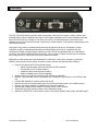
Product Manual ICC1-232 RS-232 Display Controller, 1-way Control Ver. 4 May 6, 2015 Overview ............................................................................................................................................. 3 Specifications ...................................................................................................................................... 4 Physical ................................................................................................................................................... 4 Rear Panel ............................................................................................................................................... 4 iCC-Net .................................................................................................................................................... 4 Includes ................................................................................................................................................... 4 Options .................................................................................................................................................... 4 Installation ......................................................................................................................................... 5 AC Power Test.......................................................................................................................................... 5 RS-232 Control Wiring .............................................................................................................................. 5 RF Coax and iCC-Net Operation ................................................................................................................. 5 RS-232 Control Codes ............................................................................................................................... 5 Setting Device Number and Parameters ..................................................................................................... 6 Unit Address Switch Settings ..................................................................................................................... 7 Installation Process and Documentation ..................................................................................................... 7 RS-232 Control Wiring .............................................................................................................................. 7 Power-Up and Lock Logic .......................................................................................................................... 8 Input Selects ............................................................................................................................................ 8 TV Troubleshooting ............................................................................................................................. 9 NEC –AVT TVS ......................................................................................................................................... 9 Sharp RS-232 Control ............................................................................................................................... 9 RS-232 Control Protocol ................................................................................................................... 10 Overview ................................................................................................................................................10 Command String Structure .......................................................................................................................10 Writing Your Own Control Code ................................................................................................................11 RS-232 Commands............................................................................................................................ 12 iC-Net Zones ..................................................................................................................................... 14 System Map....................................................................................................................................... 15 Typical RF and ICC-Net Signal Flow .................................................................................................. 16 Safety Instructions ........................................................................................................................... 17 Limited Warranty and Disclaimer ..................................................................................................... 18 Contemporary Research 2 ICC1-232 Manual The ICC1-232 RS-232 Display Controller delivers economical 1-way control for power, volume, channels, and available control lockout commands, receiving iCC-Net network commands over the same broadband coax that carries the CATV channels. Compact in size and price, the ICC1-232 features discrete power control and intelligent tuning from a channel list stored in onboard non-volatile memory. Tuning options include analog- and HDTV-format channels. High-speed 1-way control is possible through the same RF cable that carries the TV channels, creating networked operation of distributed media systems without adding control wiring. Compatible with the Contemporary Research Display Express software, the ICC1-232 can be networked with up to 4000 display controllers. For custom systems applications, the ICC1-232 and other CR display controllers can be accessed from a single RS-232 or Telnet port on an ICE-HE Ethernet Head End. Applications include signage and video distribution for retail stores, theme parks, museums, government facilities, sports venues, worship spaces, convention centers, airports and corporate video networks.. Controls most brands of RS-232-controlled displays — Delivers absolute power control with discrete RS-232 commands — Tunes analog or HDTV format channels — Intelligent volume level and mute operation — Enables available control lockout commands Networks with up to 4,000 TVs through the ICE-HE Ethernet Head End Receives 1-way individual and zone commands from a single RS-232/Telnet port on the ICE-HE Head End Provides LED feedback for network and RS-232 control Restores all power and channel status after loss of power from data stored in non-volatile memory Mounts on the back of display for simplified control and RF installation Operates with Display Express software, as well as custom control systems Includes RF loop cable, mounting Velcro, and 12VDC power supply Optional CC-COM RS-232 control cable or custom CC-232 cable (specify make, model, and cable length) Contemporary Research 3 ICC1-232 Manual Physical Size: Weight: Enclosure: Mounting: Rear Panel RF In RF Out: Net LED: RS-232: Tx LED: Rx LED: Power In: DIP Switches: iCC-Net Operation: Data Receive: 5.5" [140mm] wide x 1.1" [28mm] height x 3.4" [86mm] deep 8 oz [226g] All aluminum with durable black powder coat paint Mounts rear of TV ‘F’, female, 75 ohm impedance, RF from CATV system, iCC-Net control ‘F’, female, 75 ohm impedance, RF to TV, less than -1.5 dbmV loss Green LED for iC-Net bus and DC power, flashes once per second if active DB-9 male connector, baud rates from 1200 to 115K baud Optional CC-232 RS-232 available to match specific makes and models Red LED lights when RS-232 information is sent Yellow LED lights when RS-232 information is received 2.1mm coaxial jack (inside center conductor positive), 75 mA maximum 11.5 to 16.5 VDC, 12 VDC typical (may be unregulated) Located on bottom of unit, sets RS-232 code operation and device number 1-way control, carried over the same RF coax connection as TV channels Mid-band VHF, 74.7 MHz, sent from ICC-HE -25 to +35 dBmV signal level Includes RF Loop cable, 18" 12 VDC power supply, 500 mA, (domestic US shipments only) Mounting Velcro Options CC-COM Null Modem cable, 6’ CC-232 RS-232 Control Cable (specify make, model, and length) 12 VDC power supply, 100 mA, (domestic US shipments only) Contemporary Research 4 ICC1-232 Manual AC Power Test 1. Insert DC power supply plug into 12 VDC jack. 2. Plug power adaptor into AC wall outlet. 3. The Net LED should turn on and stay lit. 4. When an RF feed is connected to RF with an installed ICE-HE, LED will blink once a second RS-232 Control Wiring 1. Attach the CC-RS-232 or custom RS-232 cable to the ICC1-232 control port. 2. Connect the cable to the display’s RS-232 control input. RF Coax and iCC-Net Operation 1. Connect the TV to CATV and observe quality of RF broadcasting. A low-quality CATV system can also affect performance of the iCC-Net commands. If needed, fix CATV problems before installing the system. 2. Connect the CATV RF Coax cable into the RF In input on the ICC1-232. 3. If the iCC-Net signal is operating, the Net LED will blink once per second. 4. Connect the RF loop cable from the RF Out jack to the TV’s RF connector (remember, you lose less than 1.5 dbmV by going through the ICC1-232’S internal RF tap). RS-232 Control Codes Presently, one control type is installed at the factory, updateable to other types through the RF or via RS-232. Make Type Legacy/Specialty Enseo Revolution HD Samsung Sampo SunBrite Westinghouse ProAV Contemporary TVs LG NEC NEC NEC Panasonic Samsung Sharp LCD Tuner LCD LCD LCD LCD LCD Contemporary Research LCD LCD LCD LCD LCD LCD LCD Notes Unit controls associated hotel TV Ex-Link (tunes only up to ch. 63) No volume or mute control Older M-series with AVT tuner New M,P,S,V,X-AVT and E-series TVs E-series LRU and LRG series MD, ME, HD series commercial TVs Universal Sharp control. Send H9,1 to set fix Sharps that have tuning bug, H9,0 for default, input selection added. 5 ICC1-232 Manual Installation Setting Device Number and Parameters In the next step, you’ll need to set up the device number and operation parameters for the ICC1-232. Turn the enclosure so that the DIP switches are on the bottom as shown. 1. Make sure S2 Switch 6 is OFF (unit in Device mode). 2. Set the Device number by turning on the switches that add up to the desired device number. For example, for Device #259, turn on S1 switches 1 and 2 (3), S2 switch 1 (256) Zone Switch Settings To define the controller’s Zone #, use the following pattern of switches ON for the S2 DIP. Zone 1 2 3 4 5 6 7 8 9 10 11 12 13 14 15 Value 256 512 768 1024 1280 1536 1792 2048 2304 2560 2816 3072 3328 3584 3840 Contemporary Research 1 2 256 X 512 X 4 1024 2048 X X X X X X X X 3 X X X X X X X X X X X X X X 6 X X X X X X X X ICC1-232 Manual Unit Address Switch Settings The unique address of the controller is the combination of the values of the Zone (S2) and Unit (S1) switches. For example, the first controller in Zone 1 would be set to Zone 1 (256) in S2 and 1 (1) on S2, or 257. To control all the displays in Zone one, Display Express sends a command to device 256. To control just the first unit, create a Preset addressed to 257. Installation Process and Documentation Most dealers will pre-configure the controller’s address before hanging displays. After setting the address, use a label that states the unit’s address and location. Some use this method: Room 305 - 515 - 12/2 The first identifies the location/name of the display. The second shows the specific address. The last set shows the switches in S1/S2 that are set to ON. It’s a good idea to define all this first in a spreadsheet, with the columns defining the name, address, S1 and S2 ON settings. Then, one person can set up all the controllers and label them. Once the controller is configured and labeled, it’s easier for less-trained installers to Velcro the controller on the back of the display, provide power, and hang the displays. It’s much easier to pre-configure ahead of time than perform the task once the displays are installed. RS-232 Control Wiring 1. Connect the CC-232 cable from the ICC1-232 to the display. 2. Mount the ICC1-232 to the TV using included Velcro tape. 3. Connect DC power to unit. For those who make their own cables: Pin 5 = Ground (GND) Pin 2 = Receive (RX) Pin 3 = Transmit (TX) Contemporary Research 7 ICC1-232 Manual Power-Up and Lock Logic The ICC1-232 remembers the current power and Lock state of the connected TV so that the controller can restore power and operation lock to the TV when AC power is restored. Some TVs, such as LG, will lose the locked state (no local button or IR control) when the set loses AC power. Other sets may not automatically power back on when AC power is restored. To deal with this issue, after every power-up or reset, the ICC1-232 will transmit its current (last commanded) power control string (Power On or Power Off) to the TV, as well as work to restore the Lock state. If the TV was On and Locked when power was lost, the controller will send a Power On command when power is restored, then sends a Lock command after a time delay. This assures that the TV stays locked when it is automatically powered up after a reset. If the TV was Locked and Off when power was lost, the controller will send a Power Off command every 16 seconds when power is restored. When a command is sent to turn the TV on, the controller will also send a Lock command after a time delay. Input Selects The code sets listed a Contemporary TVs in the list on Page 5 have the ability to select inputs from a special channel command, 0-NNN. For example, a 0-211 command would send the TV to the HDMI 1 input. For some makes, such as LG, you need to send a TV/Tuner command (0-200) to restore the TV to the current channel. For other sets, sending a channel command automatically selects the tuner if it’s at a different input. The command list covers all the possibilities, not all sets have every option. 115=Captions 200=TV/Tuner 201=Video1 202=Video2 203=Video3 204=S-Video1 205=S-Video2 Contemporary Research 206=Component1 207=Component2 208=RGB1 209=RGB2 210=RGB3 8 211=HDMI1 212=HDMI2 213=HDMI3 214=HDMI4 215=HDMI5 ICC1-232 Manual NEC –AVT TVS TV responds erratically to RS-232 commands, especially channel tuning. Note that older sets with AVT tuners may need a firmware update to perform consistently (often a set of three firmware updates). If the set responds erratically to commands, often for channel commands, check with NEC support for firmware information. Also, we have two commands sets for NEC AVT sets. The standard protocol works with all current models of displays, the alternative code set works with older AVT models where we send emulated IR channel commands instead of modern direct-access channel commands. A third code set works with NEC E-series TVs with integrated tuner. Sharp RS-232 Control While the Sharp RS-232 protocol generally works well, there are several known issues with how the sets perform. Sets will turn off from an RS-232 OFF command, but won’t turn on Sharp sets are shipped in an Energy Star mode that turns off the RS-232 port when the TV is off – so it’s not listening when you send an ON commands. We have a fix for this built into our Sharp control command for ON – use this sequence to fix the issue: Send an OFF command through the Display Express system, using our software, our IC Send app, or your control system Manually turn the Sharp TV(s) on Send an ON command through the DX system. Along with the ON command, we send a command that enables full-time RS-232 operation TVs refuse to activate the RS-232 from the standard ON command Sharp tech support warns that there may be sets that don’t respond to the command that we (as well as AMX and Crestron) send to enable the port. In this case, you will need the SERVICE manual for that specific model and serial #. That will include the hidden menus you will need to access to fix the problem. We have a PDF we’ve put together showing how the typical Sharp Public Mode setup is performed, but your set could need a different sequence. TVs have a problem accessing XXX-1 channels, works fine with XXX-2 and other sub-channels This bug pops up frequently. The symptom is that, when you watch the TV’s on-screen feedback, the tuner will show the correct channel, attempts to change the channel, but snaps back to the previous channel. This only happens with -1 channels; channels that have a -2 and above minor channel will work fine. The problem is frequent enough that we have a fix for this in our Sharp code: In Display Express software, send a Special Command with the text “H9,1″ to the affected Sharp sets In IC Send, use an H9 in the first field, 1 in the second, and the device # or Zone, then Send the command Send the H9,1 command from your control software If all the Sharps in system have this issue, send the command to All controllers (4095) – only controllers with Sharp protocol will be affected Contemporary Research 9 ICC1-232 Manual Overview RS-232 control for up to 4000 TV Controllers is provided through an iC-series Head-End Network Controller. The ICE-HE Ethernet Head End manages iC-Net communication over RF Coax to ICC1 (1-way) and ICC2 (2-Way) TV Controllers. Each TV Controller is assigned a unique device number from 1 to 4000 to which control commands are addressed. The devices are organized into 16 zones of 255 devices. All the devices in each zone will respond to a single “virtual device number” — one device number that represents all devices in each zone. There is also a global device number, 4095, that will command all devices in the system. This feature dramatically speeds up system operation and programming, because one command can affect an entire group of devices—or all. To take advantages of this feature, review the section iC-Net SmartZones in this manual. In ABC-Net, we reserve the first group of devices, 1-255, for components operating on a connected control system. Zones 1-16 are used for CR TV Controllers, Video Display Controllers and Tuners. As it’s unlikely any system will use all 4000 devices, this may be a good device standard for your system as well. The Remote RS-232 port on the Head-End Network Controller can communicate from 1200 to 38.4K baud. The factory default setting is 19.2K baud, 8 data bits, No parity, and 1 stop bit. Command String Structure Characters in command strings are expressed in a combination of hex and ASCII characters. For clarity, the following protocol examples use the following conventions: Single-byte hex numbers are preceded by the ‘$’ symbol ASCII characters or strings are enclosed in single quotes Numbers not marked as hex or ASCII are a single decimal byte Parameters shown in < > brackets are single byte A series of multiple commands or parameters are set apart by [ ] brackets Commas separate the bytes, but are not part of the protocol Double quotes enclose the command string, but are not part of the protocol Command format: “$A5,<dh>,<dl>,<ncb>,<cmd1>,<parameter> [<cmdN>]" $A5 <dh> <dl> <ncb> <cmd1> <parameter> [<cmdN>] Starts the command The zone or high order byte of the device* The unit or low order byte of the device (0 for global zone) The number of command bytes to follow The first command byte Command parameters (not used by all commands) Multiple commands can be concatenated, with byte count added to <ncb> Contemporary Research 10 ICC1-232 Manual Writing Your Own Control Code While most IC systems use our Display Express software to control displays, a growing number of integrator are writing their own control applications, using AMX, Crestron, RTI, or other platforms. We encourage creative solutions, and are happy to support those who take advantage of our protocol. From our history of support activity, we are providing a few tips to help you on your way. Device Numbers iC-Net devices are arranged with a zone structure, arranged in 15 groups of 256 devices. The first address in the group represents the entire zone. For example, Zone 2’s group address is 512 (2*256). When a command is sent to 256, all controllers in that group will respond as one. The Device values reflect that structure. The first number <dh> is the zone, from 1-15. The second defines the unique address of the device, 1-255). For example, a command sent to Device 256, which triggers all the units in Zone 1, would be expressed as $A5, 1, 0 (first zone, device zero). A command sent to 257 would be $A5, 1, 1 (first zone, device 1 in the zone). See iC-Net Zones toward the end of this manual. String Format Every software application has a different denotation for handling hex, ASCII, and decimal formats. The examples in this manual are in AMX format, which is understood by many in the control industry: Hex values begin with a dollar ($) symbol ASCII values are enclosed in single quotes Decimal values are shown as normal If you plan on using a mixed-format structure for commands, convert the symbols to the types required by your software application. For example, a Tune Channel 2-3 command to device 260 could be shown several ways: AMX Mixed Format = “$A5,1,4,5,’TH’,2,2,3” AMX Hex Format “$A5 $01 $04 $05 $54 $48 $02 $02 $03” Standard Hex (no denotation) = A5 01 04 05 54 48 02 02 03 Crestron Hex Format = \xA5\x01\x04\x05\x54\x48\x02\x02\x03 RTI = Select port, Hex mode, enter A5 01 04 05 54 48 02 02 03 Go to www.asciitable.com for a handy Decimal/ASCII/Hex conversion chart. IC Send Download the IC Send application from our crwww.com home page or Downloads page. This easy-to-use tool can send commands to an IC-HE Head End RS-232 or Ethernet port. As you test your code, the program will come in handy to prove the system is operating properly, or reset things you’ve changed. Contemporary Research 11 ICC1-232 Manual Command Power Power Off P0 “$A5,<dh>,<dl>,2,’P0’ ” (6 bytes) Power On P1 “$A5,<dh>,<dl>,2,’P1’ ” (6 bytes) Power Toggle PT “$A5,<dh>,<dl>,2,’PT’ ” (6 bytes) Volume VL “$A5,<dh>,<dl>,3,’VL’,<vol level>” (7 bytes) RS-232 Control Sets TV volume level 0 = Mute 1 – 63 = Minimum level (1) to maximum volume (63) T0 “$A5,<dh>,<dl>,3,’T0’<type> ” (7 bytes) – Sets RS-232 control codes Identical to on-screen menu 45700 command on Page 8. Specify value to match make and model of video display S0= “$A5,<dh>,<dl>,3,’S0’,<format>” (7 bytes) Tuning Format Description 0=CATV 1=Off-Air 2=IRC 3=HRC 4=Cable Auto Tuning Style Not always used by modern displays – normally set by TV on-screen menus H1= “$A5,<dh>,<dl>,3,’H1’,<style>” (7 bytes) 1 = 5-digit CableCard style tuning (1-9999) 2 = Virtual HD Major-Minor tuning (tunes to virtual channel ID in display) 3 = Physical HD Major-Minor tuning (physical channel, minor digital) TC Response H2= “$A5,<dh>,<dl>,3,’H2’,<response>” (7 bytes) This pre-sets how the ICC1-232 will respond to TC tuning commands. Control String UX 0= Ignore, use current settings 1= Analog Only 2= Digital (For CableCard applications only) "$A5,<dh>,<dl>,2+string length>,'UX'<string>" (variable bytes) Sends an RS-232 string (ASCII, decimal, or hex) directly to the TV display. Ex: "$A5,1,2,6,'UX, 'PON', 13" Sends PON, followed by carriage return (device 258) Contemporary Research 12 ICC1-232 Manual RS-232 Commands Command Channel Up TU Description NA Channel Dwn TD NA T Channel Prev Force Channel Select Channel TP TC TT NA “$A5,<dh>,<dl>,3,’TC’, <channel>” (7 bytes) – Tunes to a specific channel 2-127 “$A5,<dh>,<dl>,2,’TT’,<channel>” (7 bytes) – Same as TC Tune HD TH “$A5,<dh>,<dl>,5,’TH’,<H1>,<Major>,<Minor>” (9 bytes) – Digital Tuning Normally, the H1 parameter is 0, allowing the ICC1-232 to use the current H1 tuning format, but it could be used to force a different tuning option. When the display is set to the H1=1 mode, 1-part digital channel, the first byte is (x*256), and the last byte is the value you add to state the channel number. In H1=2 or 3 modes, the bytes represent the Major and Minor channel numbers. Ex: Select Channel Tune Ring TT TR “$A5,1,4,5,’TH’,1,2,3” Device 260, channel 515 (512 +3) “$A5,1,4,5,’TH’,2,2,3” Device 260, virtual channel 2-3 “$A5,1,4,5,’TH’,3,2,3” Device 260, physical channel 2, minor 3 See Page 5 for instructions on using the TH command to select inputs. “$A5,<dh>,<dl>,2,’TT’,<channel>” (7 bytes) – Same as TC “$A5,<dh>,<dl>,<ncb>,’TR’, [<chan 1>, <chan N>]” (variable bytes) This command stores a Tune Ring, Analog channels only, a series of preset channels accessed by channel up/down commands. This is only for old Smart TVs. Control Lock LM Ex1: “$A5,<dh>,<dl>,6,’TR’, 5,4,8,11” sets ring to channels 5, 4, 8 and 11 Tip: The ring follows the stored order, channels do not have to be in ascending order Ex2: “$A5,<dh>,<dl>,8,’TR’, $82,5,$87,11” sets channels 2-5 and 7-11. You can specify a range using MSB bit for the first channel; the next byte is the last. “$A5,<dh>,<dl>,3,'LM',<control>” (7 bytes) 0 = Off (unlocked) 1 = On (locked) Locks out display commands from an IR remote or front-panel buttons. Feature is not available for all models of displays. Check with CR Tech Support if this function is important to your application. “$A5,<dh>,<dl>,3,'H9',<control>” (7 bytes) Used for Sharp control firmware 3.2. Sharp Tuning H9 Send IR H9,1 = Sharp -1 tuning fix (set can't tune a -1 channel, does fine on others) H9,0 = Standard Sharp control LQ= “$A5,<dh>,<dl>,3,’LQ’,<IR Code>” (7 bytes) Emulates an IR command for special applications: 100=Info 115=Captions 22=Channel Up 23=Channel Down Contemporary Research 13 ICC1-232 Manual To simplify controlling groups of devices, iC-Net is divided into 15 Zones of 255 devices. All the devices within each zone can be controlled simultaneously by sending a command to a single virtual device number. For example, noting the zone chart below, if we send a Power On command to device #256, any TV controller numbered between 257 and 511 will instantly turn on. If we send a Power Off command to device #4095, all devices in the system will turn off. The ICC1-IR and ICC1-232 controllers typical for many SignStream display control systems are designed to follow a Zone address format. You can use the 4 top switches in the second DIP switch (S2) to define the controller’s Zone. You could stop at that point, or use the upper switches (S1) to define the controller’s address within the Zone. For example, setting S2/1 On and S1/2 On defines that the controller is part of Zone 1 (256), and is the second unit in the Zone (2). The unique address of the controller would be 258 (256 + 2) Zone 1 2 3 4 5 6 7 8 9 10 11 12 13 14 15 All Zones Device # 256 512 768 1024 1280 1536 1792 2048 2304 2560 2816 3072 3328 3584 3840 4095 Unit 1-255 1-255 1-255 1-255 1-255 1-255 1-255 1-255 1-255 1-255 1-255 1-255 1-255 1-255 1-255 Total Device # 257-511 512-767 769-1023 1025-1279 1281-1535 1537-1791 1793-2047 2049-2303 2305-2559 2561-2815 2817-3071 3073-3327 3329-3583 3585-3839 3841-4094 Tip: While many applications can use just the Zone number, it’s a good practice to assign a unique Unit number to each controller in the zone. This allows the system software to address individual controllers if necessary. Contemporary Research 14 ICC1-232 Manual One of the key tasks for iC-Net integrators is to create a logical System Map, assigning device numbers to TV controllers so they fall into logical zones. The device mapping could be sorted by type or location; whichever suits the application. iC-Net Zone 1 2 3 4 Zone W 1st Floor W 2nd Floor E 1st Floor E 2nd Floor Room Device S1 S2 W151 W152 W153 W154 257 258 259 260 1 2 1+2 3 1 1 1 1 513 514 515 516 1 2 1+2 3 2 2 2 2 769 770 771 772 1 2 1+2 3 1+2 1+2 1+2 1+2 1025 1024 1025 1026 1 2 1+2 3 3 3 3 3 1281 1282 1283 1 2 3 1+3 1+3 1+3 1537 1538 1 2 2+3 2+3 1793 1794 1795 1796 1 2 1+2 3 3+3 3+3 3+3 3+3 2049 2050 1 2 4 4 W251 W252 W253 W254 E151 E152 E153 E154 E251 E252 E253 E254 5 Coffee Areas G100 G150 G151 6 Day Care TV 1 TV 2 7 Hallways W1 W2 E1 E2 8 Office Admin A/V Center All Zones Contemporary Research All 256 512 768 1024 1280 1536 1792 2048 4095 15 ICC1-232 Manual The diagram below shows the structure of a typical Contemporary Research media retrieval system. One of the key aspects for iCC-Net communication is to provide a forward and return (sub-channel) path for data if you’re using ICC2 2-way TV Controllers. Contemporary Research 16 ICC1-232 Manual Read before operating equipment. 1. Cleaning - Unplug this product from the wall outlet before cleaning. Do not use liquid cleaners or aerosol cleaners. Use a damp cloth for cleaning. 2. Power Sources - Use supplied or equivalent UL/CSA approved low voltage DC plug-in transformer. 3. Outdoor Antenna Grounding - If you connect an outside antenna or cable system to the product, be sure the antenna or cable system is grounded so as to provide some protection against voltage surges and built-up static charges. Section 810 of the National Electrical Code, ANSI/NFPA No. 70, provides information with respect to proper grounding of the mast and supporting structure, grounding of the leadin wire to an antenna discharge unit, size of grounding conductors, location of antenna discharge unit, connection to grounding electrodes, and requirements for the grounding electrode. 4. Lightning - Avoid installation or reconfiguration of wiring during lightning activity. 5. Power Lines - Do not locate an outside antenna system near overhead power lines or other electric light or power circuits or where it can fall into such power lines or circuits. When installing an outside antenna system, refrain from touching such power lines or circuits, as contact with them might be fatal. 6. Overloading - Do not overload wall outlets and extension cords as this can result in a risk of fire or electric shock. 7. Object and Liquid Entry - Never push objects of any kind into this product through openings as they may touch dangerous voltage points or short out parts, resulting in a fire or electric shock. Never spill liquid of any kind on the product. 8. Servicing - Do not attempt to service this product yourself as opening or removing covers may expose you to dangerous voltage or other hazards. Refer all servicing to qualified service personnel. 9. Damage Requiring Service - Unplug this product from the wall outlet and refer servicing to qualified service personnel under the following conditions: When the power supply cord or plug is damaged. If liquid spills or objects fall into the product. If the product is exposed to rain or water. If the product does not operate normally by following the operating instructions. Adjust only those controls that are covered by the operating instructions. An improper adjustment of other controls may result in damage and will often require extensive work by a qualified technician to restore the product to its normal operation. If the video product is dropped or the cabinet is damaged. When the video product exhibits a distinct change in performance, this indicates a need for service. * Note to CATV system installer: This reminder is provided to call CATV system installer's attention to Article 820-40 of the National Electrical Code (Section 54 of Canadian Electrical Code, Part I), that provides guidelines for proper grounding and, in particular, specifies that the cable ground shall be connected to the grounding system of the building as close to the point of cable entry as possible. Contemporary Research 17 ICC1-232 Manual Contemporary Research Corporation (CR) warrants this product to be free from defects in material and workmanship under normal use for a period of two years from the date of purchase from CR. Should such a defect occur CR will repair or replace, at their option, the defective product at no cost for parts or labor. This warranty extends to product purchased directly from CR or an Authorized CR Dealer. Consumers should inquire from selling dealer as to the nature and extent of the dealer's warranty, if any. All warranty claims must be shipped pre-paid to the factory. Call or fax to obtain a Return Material Authorization (RMA) number. CR is not liable for any damages caused by any of its products or for the failure of any products to perform, including any lost profits, lost savings, incidental damages, or consequential damages. CR is not responsible for any claim made by a third party or made for you by a third party. This limitation of liability applies whether damages are sought, or a claim is made, under this warranty or as a tort claim (including negligence and strict product liability), a contract claim, or any other claim. This limitation of liability cannot be waived or amended by any person. This limitation of liability will be effective even if CR or an authorized representative of CR has been advised of the possibility of any such damages. Some states do not allow a limitation of how long an implied warranty lasts. Some states do not allow the limitation or exclusion of incidental or consequential damages for consumer products. In such states, the limitation or exclusion of the Limited Warranty may not apply to you. This Limited Warranty gives you specific legal rights. You may also have other rights that may vary from state to state. You are advised to consult applicable state laws for a full determination of your rights. Except as expressly set forth in this Limited Warranty, CR makes no other warranties, expressed or implied, including any implied warranties of merchantability or fitness for a particular purpose. CR expressly disclaims all warranties not stated in this Limited Warranty. Any implied warranties that may be imposed by law are limited to the terms of this Limited Warranty. Contemporary Research 18 ICC1-232 Manual