1
Service Manual
DIGITAL LASER MFP
Model : SCX-4824FN/XBH
The keynote of Product
Basic : SCX-4824FN/SCX-4828FN
- Print/Copy Speed
SCX-4824FN : 24 ppm (A4) / 24 cpm (A4)
SCX-4828FN : 28 ppm (A4) / 28 cpm (A4)
- Memory
SCX-4824FN : 64MB(Max. 320MB)
SCX-4828FN : 128MB(Max. 384MB)
- Print resolrution
: 1200 dpi effective output
- ADF : 30(4824FN) / 50(4828FN) Sheet
- MP : 1 Sheet
- Toner : 2K(Initial)/ 5K(Sales)
- CPU : 360 Mhz
- PCL5e, PCL6, IBM ProPrinter, EPSON PS(4828FN)
GSPN (Global Service Partner Network)
North America : service.samsungportal.com
Latin America : latin.samsungportal.com
CIS : cis.samsungportal.com
Europe : europe.samsungportal.com
China : china.samsungportal.com
Asia : asia.samsungportal.com
Mideast & Africa : mea.samsungportal.com
ͿSamsung Electronics Co.,Ltd. September. 2008
Printed in Korea.
VERSION NO. : 1.00
CODE : 4824-FN0XBH
Contents
chapter 1 Precautions
1.1
1.2
1.3
1.4
Safety Warning ……………………………………………………
Caution for safety …………………………………………………
ESD Precautions …………………………………………………
Super Capacitor or Lithium Battery Precautions ………………
1-1
1-2
1-5
1-5
chapter 2 Product spec and feature
3URGXFW6SHFL¿FDWLRQV ……………………………………………
2.1.1 Product Overview ……………………………………………
6SHFL¿FDWLRQV …………………………………………………
2.1.3 Model Comparison……………………………………………
2.2 Summary of Product ……………………………………………
2.2.1 Printer Components …………………………………………
2.2.2 System Layout ………………………………………………
(QJLQH+:6SHFL¿FDWLRQV …………………………………
2.2.4 S/W Descriptions ……………………………………………
2-1
2-1
2-2
2-9
2-10
2-10
2-12
2-16
2-27
chapter 3 Disassembly and Reassembly
3.1 Disassembly and Reassemblyons on Disassembly …………
3.1.1 Screws used in the printer …………………………………
3.2 General Disassembly ……………………………………………
3.2.1 Front Cover ……………………………………………………
3.2.2 Rear Cover ……………………………………………………
3.2.3 Right/Left Cover ………………………………………………
3.2.4 Scan and ADF Assy …………………………………………
3.2.5 Middle Cover …………………………………………………
3.2.6 Fuser …………………………………………………………
3.2.7 LSU ……………………………………………………………
3.2.8 Main Drive Assy ………………………………………………
3.2.9 HVPS/SMPS/Main board ……………………………………
3-1
3-2
3-3
3-3
3-3
3-4
3-5
3-9
3-9
3-10
3-10
3-11
Contents
3.2.10 Transfer roller ……………………………………………… 3-12
3.2.11 Holder Pad unit……………………………………………… 3-13
chapter 4 Alignment & Troubleshooting
4.1 Alignment and Adjustments………………………………………
4.1.1 Control Panel overview ………………………………………
4.1.2 Understanding The Status LED ……………………………
4.1.3 Paper path ……………………………………………………
4.1.4 Menu Map ……………………………………………………
4.1.5 Tech Mode ……………………………………………………
4.1.6 EDC Mode ……………………………………………………
4.1.7 Abnormal Image Printing and Defective Roller ……………
4.1.8 Error Message ………………………………………………
4.2 Troubleshooting……………………………………………………
4.2.1 Procedure of Checking the Symptoms ……………………
4.2.2 The cause and solution of Bad image………………………
4.2.3 The cause and solution of the bad discharge ……………
4.2.4 The cause and solution of the malfunction…………………
4.2.5 The cause and solutions of bad environment of the software
4.2.6 Fax & Phone Problems ………………………………………
4.2.7 Copy Problems ………………………………………………
4.2.8 Scanning Problems …………………………………………
4-1
4-1
4-2
4-3
4-10
4-12
4-17
4-23
4-24
4-28
4-28
4-29
4-45
4-53
4-62
4-66
4-75
4-79
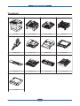
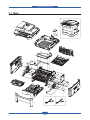
chapter 5 Exploded Views & Parts List
Thumbnail ………………………………………………………………
5.1 Main ………………………………………………………………
5.2 Cover Ass’y ………………………………………………………
5.3 Cover Middle ………………………………………………………
5.4 Frame ………………………………………………………………
5.5 Main Drive …………………………………………………………
5.6 Scan Ass’y …………………………………………………………
5-2
5-3
5-5
5-7
5-9
5-15
5-17
Contents
5.7 ADF Ass’y …………………………………………………………
5.8 Platen Ass’y ………………………………………………………
5.9 OPE Unit …………………………………………………………
5.10 Duplex Unit ………………………………………………………
5.11 Fuser………………………………………………………………
5.12 Cassette …………………………………………………………
5.13 SCF ………………………………………………………………
5-19
5-21
5-23
5-25
5-27
5-30
5-32
chapter 6 System Diagram
6.1 Block Diagram …………………………………………………… 6-1
6.2 Connection Diagram……………………………………………… 6-2
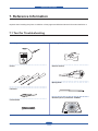
chapter 7 Reference Information
7.1 Tool for Troubleshooting …………………………………………
7.2 Acronyms and Abbreviations ……………………………………
7.2.1 Acronyms ……………………………………………………
7.2.2 Service Parts …………………………………………………
7.3 The Sample Pattern for the Test…………………………………
7.4 Selecting a location ………………………………………………
7-1
7-2
7-2
7-4
7-8
7-9
Precautions
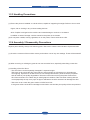
1. Precautions
In order to prevent accidents and to prevent damage to the equipment please read the precautions listed
below carefully before servicing the printer and follow them closely.
1.1 Safety Warning
(1) Only to be serviced by appropriately qualified service engineers.
High voltages and lasers inside this product are dangerous. This printer should only be serviced by a
suitably trained and qualified service engineer.
(2) Use only Samsung replacement parts
There are no user serviceable parts inside the printer. Do not make any unauthorized changes or
additions to the printer, these could cause the printer to malfunction and create electric shock or fire hazards.
(3) Laser Safety Statement
The Printer is certified in the U.S. to conform to the requirements of DHHS 21 CFR, chapter 1 Subchapter
J for Class 1(1) laser products, and elsewhere, it is certified as a Class I laser product con-forming to the
requirements of IEC 825. Class I laser products are not considered to be hazardous. The laser system
and printer are designed so there is never any human access to laser radiation above a Class I level
during normal operation, user maintenance, or prescribed service condition.
Warning >> Never operate or service the printer with the protective cover removed from Laser/
Scanner assembly. The reflected beam, although invisible, can damage your eyes.
When using this product, these basic safety pre-cautions should always be followed to
reduce risk of fire, electric shock, and injury to persons.
Service Manual
1-1
Samsung Electronics
Precautions
1.2 Caution for safety
1.2.1 Toxic material
This product contains toxic materials that could cause illness if ingested.
(1) If the LCD control panel is damaged it is possible for the liquid inside to leak. This liquid is toxic. Contact
with the skin should be avoided, wash any splashes from eyes or skin immediately and contact your
doctor. If the liquid gets into the mouth or is swallowed see a doctor immediately.
(2) Please keep Drum cartridge and Toner Cartridge away from children. The toner powder contained in the
Drum cartridge and Toner Cartridge may be harmful and if swallowed you should contact a doctor.
1.2.2 Electric Shock and Fire Safety Precautions
Failure to follow the following instructions could cause electric shock or potentially cause a fire.
(1) Use only the correct voltage, failure to do so could damage the printer and potentially cause a fire or
electric shock.
(2) Use only the power cable supplied with the printer. Use of an incorrectly specified cable could cause the
cable to overheat and potentially cause a fire.
(3) Do not overload the power socket, this could lead to overheating of the cables inside the wall and could
lead to a fire.
(4) Do not allow water or other liquids to spill into the printer, this can cause electric shock. Do not allow
paper clips, pins or other foreign objects to fall into the printer these could cause a short circuit leading to
an electric shock or fire hazard.
(5) Never touch the plugs on either end of the power cable with wet hands, this can cause electric shock.
When servicing the printer remove the power plug from the wall socket.
(6) Use caution when inserting or removing the power connector. The power connector must be inserted
completely otherwise a poor contact could cause overheating possibly leading to a fire. When removing
the power connector grip it firmly and pull.
(7) Take care of the power cable. Do not allow it to become twisted, bent sharply round corners or other
wise damaged. Do not place objects on top of the power cable. If the power cable is damaged it could
overheat and cause a fire or exposed cables could cause an electric shock. Replace a damaged power
cable immediately, do not reuse or repair the damaged cable. Some chemicals can attack the coating on
the power cable, weakening the cover or exposing cables causing fire and shock risks.
(8) Ensure that the power sockets and plugs are not cracked or broken in any way. Any such defects should
be repaired immediately. Take care not to cut or damage the power cable or plugs when moving the
machine.
(9) Use caution during thunder or lightening storms. Samsung recommend that this machine be disconnected
from the power source when such weather conditions are expected. Do not touch the machine or the
power cord if it is still connected to the wall socket in these weather conditions.
(10) Avoid damp or dusty areas, install the printer in a clean well ventilated location. Do not position the
machine near a humidifier. Damp and dust build up inside the machine can lead to overheating and
cause a fire.
(11) D
o not position the printer in direct sunlight. This will cause the temperature inside the printer to rise
possibly leading to the printer failing to work properly and in extreme conditions could lead to a fire.
(12) Do not insert any metal objects into the machine through the ventilator fan or other part of the casing, it
could make contact with a high voltage conductor inside the machine and cause an electric shock.
Service Manual
1-2
Samsung Electronics
Precautions
1.2.3 Handling Precautions
The following instructions are for your own personal safety, to avoid injury and so as not to damage the
printer
(1) Ensure the printer is installed on a level surface, capable of supporting its weight. Failure to do so could
cause the printer to tip or fall.
(2) The printer contains many rollers, gears and fans. Take great care to ensure that you do not catch your
fingers, hair or clothing in any of these rotating devices.
(3) Do not place any small metal objects, containers of water, chemicals or other liquids close to the printer
which if spilled could get into the machine and cause damage or a shock or fire hazard.
(4) Do not install the machine in areas with high dust or moisture levels, beside on open window or close to a
humidifier or heater. Damage could be caused to the printer in such areas.
(5) Do not place candles, burning cigarettes, etc on the printer, These could cause a fire.
1.2.4 Assembly / Disassembly Precautions
Replace parts carefully, always use Samsung parts. Take care to note the exact location of parts and also
cable routing before dismantling any part of the machine. Ensure all parts and cables are replaced correctly.
Please carry out the following procedures before dismantling the printer or replacing any parts.
(1) Check the contents of the machine memory and make a note of any user settings. These will be erased if
the mainboard or network card is replaced.
(2) Ensure that power is disconnected before servicing or replacing any electrical parts.
(3) Disconnect printer interface cables and power cables.
(4) Only use approved spare parts. Ensure that part number, product name, any voltage, current or
temperature rating are correct.
(5) When removing or re-fitting any parts do not use excessive force, especially when fitting screws into
plastic.
(6) Take care not to drop any small parts into the machine.
(7) Handling of the OPC Drum
- The OPC Drum can be irreparably damaged if it exposed to light.
Take care not to expose the OPC Drum either to direct sunlight or to fluorescent or incandescent
room lighting. Exposure for as little as 5 mins can damage the surface? photoconductive properties
and will result in print quality degradation. Take extra care when servicing the printer. Remove the
OPC Drum and store it in a black bag or other lightproof container. Take care when working with the
covers(especially the top cover) open as light is admitted to the OPC area and can damage the OPC
Drum.
- Take care not to scratch the green surface of OPC Drum Unit.
If the green surface of the Drum Cartridge is scratched or touched the print quality will be compromised.
Service Manual
1-3
Samsung Electronics
Precautions
1.2.5 Disregarding this warning may cause bodily injury
(1) Be careful with the high temperature part.
The fuser unit works at a high temperature. Use caution when working on the printer. Wait for the fuser to
cool down before disassembly.
(2) Do not put finger or hair into the rotating parts.
When operating a printer, do not put hand or hair into the rotating parts (Paper feeding entrance, motor,
fan, etc.). If do, you can get harm.
(3) When you move the printer
-W
hen transporting/installing the equipment be sure to hold the positions as shown in the reference
chapter.
The equipment is quite heavy and weighs approximately 13.6 Kg (including consumables), therefore pay
full attention when handling it.
-B
e sure not to hold the movable parts or units (e.g. the control panel, DADF) when transporting the
equipment.
- Be sure to use a dedicated outlet with 110V/220Vpower input.
- The equipment must be grounded for safety.
-S
elect a suitable place for installation. Avoid excessive heat, high humidity, dust, vibration and direct
sunlight.
- Provide proper ventilation since the equipment emits a slight amount of ozone.
- To insure adequate working space for the copying operation, keep a minimum clearance of 10cm (3.9”
on the left, 10 cm (3.9”) on the right and 18 cm (7.1”) on the rear.
- The equipment shall be installed near the socket outlet and shall be accessible.
- Be sure to fix and plug in the power cable securely after the installation so that no one trips over it.
Service Manual
1-4
Samsung Electronics
Precautions
1.3 ESD Precautions
Certain semiconductor devices can be easily damaged by static electricity. Such components are commonly
called “Electrostatically Sensitive (ES) Devices” or ESDs. Examples of typical ESDs are: integrated circuits,
some field effect transistors, and semiconductor “chip” components.
The techniques outlined below should be followed to help reduce the incidence of component damage
caused by static electricity.
Caution >>Be sure no power is applied to the chassis or circuit, and observe all other safety precautions.
1. Immediately before handling a semiconductor component or semiconductor-equipped assembly, drain
off any electrostatic charge on your body by touching a known earth ground. Alternatively, employ a
commercially available wrist strap device, which should be removed for your personal safety reasons prior
to applying power to the unit under test.
2. After removing an electrical assembly equipped with ESDs, place the assembly on a conductive surface,
such as aluminum or copper foil, or conductive foam, to prevent electrostatic charge buildup in the vicinity
of the assembly.
3. Use only a grounded tip soldering iron to solder or desolder ESDs.
4. Use only an “anti-static” solder removal device. Some solder removal devices not classified as “anti-static”
can generate electrical charges sufficient to damage ESDs.
5. Do not use Freon-propelled chemicals. When sprayed, these can generate electrical charges sufficient to
damage ESDs.
6. Do not remove a replacement ESD from its protective packaging until immediately before installing it. Most
replacement ESDs are packaged with all leads shorted together by conductive foam, aluminum foil, or a
comparable conductive material.
7. Immediately before removing the protective shorting material from the leads of a replacement ESD, touch
the protective material to the chassis or circuit assembly into which the device will be installed.
8. Maintain continuous electrical contact between the ESD and the assembly into which it will be installed,
until completely plugged or soldered into the circuit.
9. Minimize bodily motions when handling unpackaged replacement ESDs. Normal motions, such as
the brushing together of clothing fabric and lifting one’s foot from a carpeted floor, can generate static
electricity sufficient to damage an ESD.
1.4 Super Capacitor or Lithium Battery Precautions
1. Exercise caution when replacing a super capacitor or Lithium battery. There could be a danger of explosion
and subsequent operator injury and/or equipment damage if incorrectly installed.
2. Be sure to replace the battery with the same or equivalent type recommended by the manufacturer.
3. Super capacitor or Lithium batteries contain toxic substances and should not be opened, crushed, or
burned for disposal.
4. Dispose of used batteries according to the manufacture? instructions.
Service Manual
1-5
Samsung Electronics
Product spec and feature
2. Product spec and feature
3URGXFW6SHFL¿FDWLRQV
2.1.1 Product Overview
Concept
Target
Optimized Desktop MFP for Small Workgroup
Entry SMB
SCX-4824FN
SCX-4828FN
SSP$
3ULQW5HVROXWLRQ
$GGUHVVDEOH[GSL
86%1:
&DVVHWWH0DQXDO7UD\
,'&RS\&ORQH3RVWHU&RS\
,QLWLDO.6DOHV.
2SWLRQDO&DVVHWWH
SSP$SSP/WU
'XSOH[SSP$
3ULQW5HVROXWLRQ
$GGUHVVDEOH[GSL
86%1:
&DVVHWWH0DQXDO7UD\
'LUHFW86%
,'&RS\&ORQH3RVWHU&RS\
,QLWLDO.6DOHV.
6WDQGDUG'XSOH[3ULQW
2SWLRQDO&DVVHWWH
Service Manual
2-1
Samsung Electronics
Product spec and feature
6SHFL¿FDWLRQV
3URGXFW6SHFL¿FDWLRQVDUHVXEMHFWWRFKDQJHZLWKRXWQRWLFH6HHEHORZIRUSURGXFWVSHFL¿FDWLRQV
2.1.2.1 General Print Engine
Items
1HW'LPHQVLRQ:['[+
SCX-4824FN
SCX-4828FN
[[PP[[
[[PP[[
LQ
LQ
.JZR&RQVXPDEOH.J
.JZR&RQVXPDEOH.J
/&'
OLQH[FKDUDFWHUV
OLQH[FKDUDFWHUV
System Memory
0%
0%
,QWHUIDFH
+L6SHHG86%(WKHUQHW%DVH
+L6SHHG86%(WKHUQHW%DVH
7;
7;
:LQGRZVELW;3ELW
:LQGRZVELW;3ELW
6HUYHUELW9LVWDELW
6HUYHUELW9LVWDELW
9DULRXV/LQX[26LQFOXGLQJ5HG+DWa
9DULRXV/LQX[26LQFOXGLQJ5HG+DWa
Packing Dimension
:['[+
:HLJKWZLWK&RQVXPDEOHV
3DFNLQJ:HLJKW
26&RPSDWLELOLW\
)HGRUD&RUHa0DQGUDNHaDQG )HGRUD&RUHa0DQGUDNHaDQG
:+4/
6X6(a
6X6(a
0DF
0DF
:LQGRZV;36HUYHU
:LQGRZV;36HUYHU
9LVWDELWV
9LVWDELWV
:LUHGQHWZRUN3URWRFRO
7&3,3(WKHUWDON6103+773
7&3,3(WKHUWDON6103+773
:LUHGQHWZRUN6XSSRUWLQJ
:LQGRZV;3ELWV6HUYHU
:LQGRZV;3ELWV6HUYHU
OS
9LVWDELWV
9LVWDELWV
1HW:DUH[[
1HW:DUH[[
0DF26aa
0DF26aa
9DULRXV/LQX[26LQFOXGLQJ5HG+DWa
9DULRXV/LQX[26LQFOXGLQJ5HG+DWa
)HGRUD&RUHa0DQGUDNHa
)HGRUD&RUHa0DQGUDNHa
6X6(a
6X6(a
8QL[$77V\VWHP95HO%6'+3 8QL[$77V\VWHP95HO%6'+3
1RLVH
3RZHU5HTXLUHPHQW
2SHUDWLQJ&RQGLWLRQV
Service Manual
8;5HO[5HO[6&2[68126
8;5HO[5HO[6&2[68126
6SDUFRU6RODULV
6SDUFRU6RODULV
:DUPXS/HVVWKDQG%$
:DUPXS/HVVWKDQG%$
6WDQGE\/HVVWKDQG%$
6WDQGE\/HVVWKDQG%$
3ULQWLQJ/HVVWKDQG%$
3ULQWLQJ/HVVWKDQG%$
&RSLQJ/HVVWKDQG%$
&RSLQJ/HVVWKDQG%$
a9$&+]$
a9$&+]$
a9$&+]$
a9$&+]$
7HPSHUDWXUHçaççaç
7HPSHUDWXUHçaççaç
+XPLGLW\a5+
+XPLGLW\a5+
2-2
Samsung Electronics
Product spec and feature
Items
3RZHU&RQVXPSWLRQ
SCX-4824FN
SCX-4828FN
5HDG\/HVVWKDQ:
5HDG\/HVVWKDQ:
$YHUDJH/HVVWKDQ:
$YHUDJH/HVVWKDQ:
0D[3HDN:
0D[3HDN:
6OHHSSRZHURII/HVVWKDQ:
6OHHSSRZHURII/HVVWKDQ:
$039
VKHHWV
VKHHWV
'XW\&\FOHPRQWKO\
8SWRSDJHV
8SWRSDJHV
07%)
8SWRSDJHV
8SWRSDJHV
0775
PLQ
PLQ
6&$1/LIH&\FOH
VKHHWVRU\HDUVZKLFKHYHU
VKHHWVRU\HDUVZKLFKHYHU
FRPHV¿UVW
FRPHV¿UVW
VKHHWVRU\HDUVZKLFKHYHU
VKHHWVRU\HDUVZKLFKHYHU
FRPHV¿UVW
FRPHV¿UVW
VKHHWVRU\HDUVZKLFKHYHU
VKHHWVRU\HDUVZKLFKHYHU
FRPHV¿UVW
FRPHV¿UVW
$')/LIH&\FOH
6(7/LIH&\FOH
3ULQW6SHFL¿FDWLRQV
Items
SCX-4824FN
SCX-4828FN
0HWKRG
/DVHU%HDP3ULQWLQJ
/DVHU%HDP3ULQWLQJ
6SHHG6LPSOH[
8SWRSSP$
8SWRSSP$
6SHHG'XSOH[
-
8SWRSSP$
)327
:DUPXSIURPVOHHS
5HVROXWLRQ
/HVVWKDQVIURPVOHHSPRGH
/HVVWKDQVIURPVOHHSPRGH
/HVVWKDQVIURPVWDQE\PRGH
/HVVWKDQVIURPVWDQE\PRGH
/HVVWKDQV
/HVVWKDQV
8SWRGSL(IIHFWLYH2XWSXW
8SWRGSL(IIHFWLYH2XWSXW
$GGUHVVDEOH[GSL
$GGUHVVDEOH[GSL
Processor
&KRUXV0+]
&KRUXV0+]
Memory
0%0D[0%
0%0D[0%
Emulation
3&/H3&/,%03UR3ULQWHU(3621
3&/H3&/,%03UR3ULQWHU(3621
36
Font
'XSOH[3ULQW
Service Manual
VFDODEOHELWPDS3RVW6FULSW
VFDODEOHELWPDS3RVW6FULSW
fonts
fonts
1$
Default
Samsung Electronics
Product spec and feature
&RS\6SHFL¿FDWLRQV
Items
6SHHG
SCX-4824FN
SCX-4828FN
6'0&XSWRFSPLQ$FSPLQ/HWWHU 6'0&XSWRFSPLQ$FSPLQ/HWWHU
0'6&XSWRFSPLQ$FSPLQ/HWWHU
0'6&XSWRFSPLQ$FSPLQ/HWWHU
[GSL
[GSL
7H[W7H[W3KRWR[GSL
7H[W7H[W3KRWR[GSL
3KRWRPRGH[GSL
3KRWRPRGH[GSL
5HVROXWLRQ(QKDQFHG
[GSL
[GSL
)&27IURP6WDQGE\
$SSUR[VHFRQGV3ODWHQ
$SSUR[VHFRQGV3ODWHQ
PRGH
$SSUR[VHFRQGV$')
$SSUR[VHFRQGV$')
=RRP5DWH
aSODWHQa$')
aSODWHQa$')
0XOW\&RS\
aSDJHV
aSDJHV
6SHFLDO&RS\
1XSFRS\XSXS
1XSFRS\XSXS
&ROODWLRQ&RS\<HV
&ROODWLRQ&RS\<HV
$XWR)LW&RS\<HV3ODWHQRQO\
$XWR)LW&RS\<HV3ODWHQRQO\
VLGH&RS\<HV3ODWHQRQO\
VLGH&RS\<HV3ODWHQRQO\
&ORQH<HV3ODWHQRQO\
&ORQH<HV3ODWHQRQO\
3RVWHU<HV3ODWHQRQO\
3RVWHU<HV3ODWHQRQO\
1$
1$
5HVROXWLRQ2SWLFDO
'XSOH[&RS\
6FDQ6SHFL¿FDWLRQV
Items
SCX-4824FN
SCX-4828FN
&RPSDWLELOLW\
7ZDLQ6WDQGDUG:,$6WDQGDUG
7ZDLQ6WDQGDUG:,$6WDQGDUG
0HWKRG
&RORU&,6
&RORU&,6
6FDQ6SHHGWKURXJK$')
/LQHDULW\$SSUR[VHF
/LQHDULW\$SSUR[VHF
*UD\$SSUR[VHF
*UD\$SSUR[VHF
&RORU$SSUR[VHF
&RORU$SSUR[VHF
/LQHDULW\$SSUR[VHF
/LQHDULW\$SSUR[VHF
*UD\$SSUR[VHF
*UD\$SSUR[VHF
&RORU$SSUR[VHF
&RORU$SSUR[VHF
5HVROXWLRQ2SWLFDO
[GSL
[GSL3ODWHQ3&6&$1
5HVROXWLRQ(QKDQFHG
[GSL
[GSL
(IIHFWLYH6FDQ/HQJWK
PP
PP
(IIHFWLYH6FDQ:LGWK
PP
PP
&RORU%LWGHSWK
,QWHUQDOELW([WHUQDOELW
,QWHUQDOELW([WHUQDOELW
%:%LWGHSWK
ELWIRU7H[WPRGHELWIRU*UD\PRGH
ELWIRU7H[WPRGHELWIRU*UD\PRGH
Gray Scale
/HYHOV
/HYHOV
6FDQ6SHHGWKURXJK3ODWHQ
Service Manual
Samsung Electronics
Product spec and feature
)D[6SHFL¿FDWLRQV
Items
&RPSDWLELOLW\
$SSOLFDEOHOLQH
SCX-4824FN
SCX-4828FN
,787*URXS(&0
,787*URXS(&0
3XEOLF6ZLWFKHG7HOHSKRQH1HWZRUN3671
3XEOLF6ZLWFKHG7HOHSKRQH1HWZRUN3671
RUEHKLQG3$%;
RUEHKLQG3$%;
Modem Speed
.ESV
.ESV
7UDQVPLVVLRQ6SHHG
$SSUR[VHFRQGVSHUSDJH
$SSUR[VHFRQGVSHUSDJH
&RPSUHVVLRQ0RGH
0+05005-%,*-3(*
0+05005-%,*-3(*
6FDQ6SHHG
6WG$SSUR[VHFRQGVSHUSDJH/75
6WG$SSUR[VHFRQGVSHUSDJH/75
)LQH6)LQH$SSUR[VHFRQGVSHUSDJH
)LQH6)LQH$SSUR[VHFRQGVSHUSDJH
/75
/75
5HVROXWLRQ
Memory
0D[[GSL
0D[[GSL
6WDQGDUG[GSL
6WDQGDUG[GSL
)LQH[GSL
)LQH[GSL
6XSHU)LQH[GSL
6XSHU)LQH[GSL
3KRWR[GSL
3KRWR[GSL
&RORU[GSL
&RORU[GSL
0%$SSUR[SDJHVDW,787&KDUW 0%$SSUR[SDJHVDW,787&KDUW
0D[ORFDWLRQVWRVWRUHWR*URXS'LDO
0D[ORFDWLRQVWRVWRUHWR*URXS'LDO
locations
locations
)D[)RUZDUG<HV2Q2II
)D[)RUZDUG<HV2Q2II
%URDGFDVWLQJXSWRORFDWLRQV
%URDGFDVWLQJXSWRORFDWLRQV
&RYHUSDJH<HV
&RYHUSDJH<HV
'HOD\HGID[<HV
'HOD\HGID[<HV
0HPRU\5;<HV
0HPRU\5;<HV
9RLFH5HTXHVW1R
9RLFH5HTXHVW1R
77,<HV
77,<HV
57,<HV
57,<HV
3ROOLQJ1R
3ROOLQJ1R
(DUWK5HFDOO1R
(DUWK5HFDOO1R
$XWR5HGXFWLRQ<HV
$XWR5HGXFWLRQ<HV
):5HPRWHXSJUDGH<HV
):5HPRWHXSJUDGH<HV
-XQN)D[EDUULHU
<HV
<HV
6HFXUH5HFHLYH
<HV
<HV
Memory Back-up
<HV0D[KRXUV
<HV0D[KRXUV
$XWR'LDO
8SWR/RFDLRQV
8SWR/RFDLRQV
Functions
Service Manual
Samsung Electronics
Product spec and feature
2.1.2.6 Paper Handling
Items
6WDQGDUG&DSDFLW\
SCX-4824FN
SCX-4828FN
VKHHW&DVVHWWH7UD\VKHHW0XOWL
VKHHW&DVVHWWH7UD\VKHHW0XOWL
3XUSRVH7UD\#J̅
3XUSRVH7UD\#J̅
0D[LPXP&DSDFLW\
VKHHWV#J̅
VKHHWV#J̅
3ULQWLQJ0D[6L]H
[PP[
[PP[
0LQ6L]H
[PP[
[PP[
VW7UD\&DSDFLW\
VKHHWV#J̅
VKHHWV#J̅
Media Sizes
$$/HWWHU/HJDO([HFXWLYH)ROLR2¿FLR $$/HWWHU/HJDO([HFXWLYH)ROLR2¿FLR
,62%-,6%
,62%-,6%
3ODLQSDSHU7KLFN3DSHU7KLQ3DSHU
3ODLQSDSHU7KLFN3DSHU7KLQ3DSHU
5HF\FOHG3DSHU$UFKLYH3DSHU
5HF\FOHG3DSHU$UFKLYH3DSHU
0HGLDZHLJKW
aOEWRJ̅
aOEWRJ̅
Sensing
Paper empty sensor
Paper empty sensor
QG7UD\&DSDFLW\
VKHHWV#J̅
VKHHWV#J̅
Media Sizes
$/HWWHU/HJDO)ROLR2¿FLR
$/HWWHU/HJDO)ROLR2¿FLR
Media types
3ODLQSDSHU7KLFN3DSHU7KLQ3DSHU
3ODLQSDSHU7KLFN3DSHU7KLQ3DSHU
5HF\FOHG3DSHU$UFKLYH3DSHU
5HF\FOHG3DSHU$UFKLYH3DSHU
0HGLDZHLJKW
aOEWRJ̅
aOEWRJ̅
Sensing
Paper empty sensor
Paper empty sensor
0DQXDO7UD\&DSDFLW\
VKHHWV#J̅
VKHHWV#J̅
Media Sizes
$$$/HWWHU/HJDO)ROLR2¿FLR
$$$/HWWHU/HJDO)ROLR2¿FLR
([HFXWLYH,62%-,6%[0RQDUFK
([HFXWLYH,62%-,6%[0RQDUFK
1R'/&&
1R'/&&
3ODLQSDSHU7KLFN3DSHU7KLQ
3ODLQSDSHU7KLFN3DSHU7KLQ
3DSHU5HF\FOHG3DSHU$UFKLYH
3DSHU5HF\FOHG3DSHU$UFKLYH
3DSHU7UDQVSDUHQF\(QYHORSH/DEHOV3RVW
3DSHU7UDQVSDUHQF\(QYHORSH/DEHOV3RVW
&DUG&DUGVWRFN
&DUG&DUGVWRFN
0HGLDZHLJKW
aOEWRJ̅
aOEWRJ̅
Sensing
1$
1$
Output Stacking
VKHHWV#J̅%DVH/LQH3DSHU
VKHHWV#J̅%DVH/LQH3DSHU
Media types
Media types
6DPVXQJ3UHPLXP;HUR[11&RQGLWLRQ 6DPVXQJ3UHPLXP;HUR[11&RQGLWLRQ
'XSOH[0HGLDVL]HV
-
$/HWWHU/HJDO)ROLR2¿FLR
0HGLD7\SHV
-
3ODLQSDSHU7KLFN3DSHU7KLQ3DSHU
5HF\FOHG3DSHU$UFKLYH3DSHU
0HGLDZHLJKW
-
aOEWRJ̅
3ULQWDEOH$UHD
(QYHORSPPIURPHGJH7RS
(QYHORSPPIURPHGJH7RS
1RQ3ULQWDEOH$UHD
%RWWRP/HIW5LJKW
%RWWRP/HIW5LJKW
2WKHU0HGLDPPIURPHGJH7RS
2WKHU0HGLDPPIURPHGJH7RS
%RWWRP/HIW5LJKW
%RWWRP/HIW5LJKW
VKHHWV/HWWHU$OEJ̅
VKHHWV/HWWHU$OEJ̅
$')&DSDFLW\
Service Manual
Samsung Electronics
Product spec and feature
Items
$')'RFXPHQW6L]H
SCX-4824FN
SCX-4828FN
:LGWKaPPa
:LGWKaPPa
/HQJWKaPPa
/HQJWKaPPa
0HGLD6L]HIRU)D[DQG /HWWHU$/HJDO
/HWWHU$/HJDO
&RS\
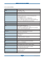
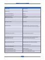
2.1.2.7 Consumables (CRU)
Items
SCX-4824FN
SCX-4828FN
7\SH
6LQJOH&DUWULGJH
6LQJOH&DUWULGJH
<LHOG
6WDQGDUG$YHUDJH&DUWULGJH<LHOG.VWDQGDUG 6WDQGDUG$YHUDJH&DUWULGJH<LHOG.VWDQGDUG
SDJHV
SDJHV
+LJK<LHOG$YHUDJHFDUWULGJH<LHOG.VWDQGDUG +LJK<LHOG$YHUDJHFDUWULGJH<LHOG.VWDQGDUG
SDJHV
SDJHV
'HFODUHGFDUWULGJH\LHOGLQDFFRUGDQFHZLWK
'HFODUHGFDUWULGJH\LHOGLQDFFRUGDQFHZLWK
,62,(&
,62,(&
/LIH'HWHFW
7RQHUJDXJHVHQVRUE\GRWFRXQW
7RQHUJDXJHVHQVRUE\GRWFRXQW
.H\
(OHFWURQLFNH\&5802QO\
(OHFWURQLFNH\&5802QO\
&RGH
0/T-D209S/MLT-D209L
MLT-D209S/MLT-D209L
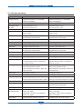
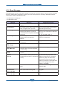
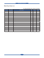
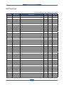
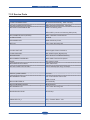
2.1.2.8 Consumables (FRU)
Image
Service Manual
Items
Life
Part code
Transfer roller
50K
Fuser
50K
Pick up rubber
50K
JC97-03062A
Friction Pad (Cassette)
50K
JC96-04743A
Friction Pad (ADF)
20K
JC97-01940A
Pick up Assy(ADF)
20K
JC97-01962A
JC66-01218A
JC96-05132A(220V)
JC96-05133A(110V)
Samsung Electronics
Product spec and feature
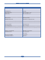
2.1.2.9 Options
Items
SCX-4824FN
SCX-4828FN
1HWZRUN
1$
1$
Memory
0%0%&/30(0&/30(0
0%0%&/30(0&/30(0
6&)
2SWLRQ6&;6$
2SWLRQ6&;6$
PS
1$
Standard
3ULQWVSHHGZLOOEHDIIHFWHGE\2SHUDWLQJV\VWHPXVHGFRPSXWLQJSHUIRUPDQFHDSSOLFDWLRQVRIWZDUHFRQQHFWLQJ
PHWKRGPHGLDW\SHPHGLDVL]HDQGMREFRPSOH[LW\
&RS\6SHHGLVEDVHGRQ6LQJOH'RFXPHQW0XOWLSOH&RS\
&RQGLWLRQ6WDQGDUGUHVROXWLRQ005-%,*0D[LPXPPRGHPVSHHG3KDVH³&´E\,7871R&KDUW0HPRU\7[
(&0
&RQGLWLRQ,7871R&KDUW6WDQGDUG5HVROXWLRQ
3OHDVHYLVLWZZZVDPVXQJSULQWHUFRPWRGRZQORDGWKHODWHVWVRIWZDUHYHUVLRQ
6RXQG3UHVVXUH/HYHO,62
0D\EHDIIHFWHGE\RSHUDWLQJHQYLURQPHQWSULQWLQJLQWHUYDOPHGLDW\SHDQGPHGLDVL]H
Service Manual
Samsung Electronics
Product spec and feature
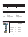
2.1.3 Model Comparison
Samsung
SCX-4824FN
Samsung
SCX-4728FN
HP
M2727nf
Speed
SSP$
SSP$
SSP$
)327
VHF
VHF
VHF
&DVVHWWH
VKHHWV
VKHHWV
VKHHWV
'XSOH[0RGXOH
1$
Default
1$
,PDJH
Printer
)$;
&DUWULGJH
..
..
6DOHV..
Processor
0+]
0+]
0+]
Memory
0%0D[0%
0%0D[0%
0%0D[0%
,QWHUIDFH
86%7;
86%7;
86%7;
Emulation
3&/3&/H
3&/3&/H36
3&/3&/H36
Modem Speed
NESV
NESV
NESV
5HVROXWLRQ6FDQ
GSL
GSL
GSL
Scan
,QSXWFDSDFLW\
$')
VKHHWV
VKHHWV
VKHHWV
&RS\
&RS\6SHHG
6'0&XSWRFSP
0'6&XSWRFSP
6'0&XSWRFSP
0'6&XSWRFSP
FSP
1$
'LUHFW86%VXSSRUW
86%+267
Dimension
:HLJKW
Service Manual
[[PP [[PP
.J
.J
[[PP
.J
Samsung Electronics
Product spec and feature
2.2 Summary of Product
7KLVFKDSWHUGHVFULEHVWKHIXQFWLRQVDQGRSHUDWLQJSULQFLSDORIWKHPDLQFRPSRQHQW
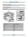
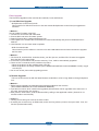
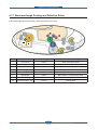
2.2.1 Printer Components
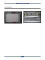
2.2.1.1 Front View
1
Document width guides
9
Document output tray
2
ADF cover
10
USB memory port
3
Control panel
11
Paper level indicator
4
Output support
12
Optional tray 2
5
Front cover
13
Toner cartridge
6
Manual tray
14
Manual tray paper width
guides
7
Tray 1
15
Scanner lid
8
Document input tray
16
Scanner glass
Service Manual
Samsung Electronics
Product spec and feature
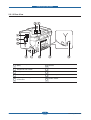
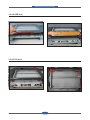
2.2.1.2 Rear View
1
Extension telephone socket
(EXT)
6
Handle
2
Telephone line socket
7
Control board cover
3
USB port
8
Rear cover
4
Network port
9
Power receptacle
5
15-pin optional tray
connection
10
Power switch
Service Manual
2-11
Samsung Electronics
Product spec and feature
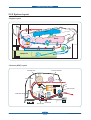
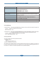
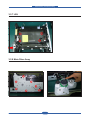
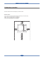
2.2.2 System Layout
- Engine Layout
LSU
DEVE
FUSER
DUPLEX
CASSETTE
- Scanner (ADF) Layout
$')52//(5
3,&.8P 52//(5
&29(523(1
$')833(5
)(('52//(5
(;,752//(5
$')/2:(5
6&$1833(5
$')*/$6S
Service Manual
:+,7(%$5
2-12
Samsung Electronics
Product spec and feature
2.2.2.1 Feeding
,WLVFRQVLVWVRIDEDVLFFDVVHWWHDQ03WUD\IRUVXSSO\LQJGLIIHUHQWW\SHVRIPHGLDHQYHORSHODEHOVSHFLDO
SDSHUGXSOH[XQLWDQGSDUWVUHODWHGWRSDSHUWUDQVIHUULQJ
1) Separation method
6HSDUDWHLWIURPWKHIULFWLRQSDGPRXQWHGWRWKHFHQWHURIWKHFDVVHWWH
2) Basic cassette
,WWDNHVDFHQWHUORDGLQJPHWKRGDQGDSSOLHVµIULFWLRQSDGVHSDUDWLQJPHWKRG
%RWKWKHVLGHJXLGHDQGWKHUHDUJXLGHFDQEHDGMXVWHGIRUIRUYDULRXVW\SHVRISDSHUVIURP$WR
OHJDOVL]HSDSHU
,WKDVDSDSHUH[LVWHQFHVHQVLQJIXQFWLRQ&DSDFLW\VKHHWVRIJHQHUDOSDSHUSDSHUDUUDQJLQJ
IXQFWLRQYDULRXVVL]HSDSHUVDFFHSWLQJIXQFWLRQ6&)SDSHUSDWKIXQFWLRQDQGGLVSOD\LQJIXQFWLRQRI
SDSHUUHPDLQLQJDPRXQW
,QWKHIURQWVLGHWKHUHLVDSDSHUOHYHOLQGLFDWRU
3) Pick-up roller
,WKDVIXQFWLRQVVXFKDVDSDSHUSLFNXSIXQFWLRQGULYLQJFRQWUROIXQFWLRQSDSHUIHHGLQJIXQFWLRQDQG
UHPRYLQJHOHFWURQLFVWDWLFIXQFWLRQ
4) Registration roller
,WKDVDSDSHUDUUDQJLQJIXQFWLRQSDSHUWUDQVIHUULQJIXQFWLRQSDSHUGHWHFWLQJIXQFWLRQMDPUHPRYLQJ
IXQFWLRQDQGVRRQ
5) MP tray
,WKDVDSDSHUDUUDQJLQJIXQFWLRQSDSHUWUDQVIHUULQJIXQFWLRQMDPUHPRYLQJIXQFWLRQDQGVRRQ
,WXVHVUXEELQJSDGPHWKRGWRIHHGVKHHWVRIJHQHUDOSDSHUVDQGHQYHORSV
6) Duplex unit
,WKDVSDSHUWUDQVIHUULQJIXQFWLRQSDSHUJXLGHIXQFWLRQMDPUHPRYLQJIXQFWLRQSDSHUVHQVLQJ
IXQFWLRQDQGPDLQERDUGVXSSRUWLQJIXQFWLRQ
,WLVGHVLJQHGIRUEDVLFDWWDFKPHQWDQGWKHGXSOH[IHHGLQJWDNHVDVLGHIHHGLQJPHWKRG8VDEOH
SDSHUVDUH$OHWWHUDQGOHJDOVL]HSDSHU
)RUUHPRYLQJDMDPRFFXUUHGLQDIURQWSDUWLWLVGHVLJQHGWRRSHQDFDVVHWWHDQGDJXLGH
,WLVGHVLJQHGWRRSHQDUHDUFRYHUWRUHPRYHDMDPLQDUHDUSDUW
7) SCF (Second Cassette Feeder)
,WLVWKHVDPHPHWKRGZLWKWKHPDLQFDVVHWWHDQGWKHFDSDFLW\LVVKHHWV
,WKDVDVHSDUDWHGULYLQJPHFKDQLVP,WLVGHVLJQHGIRUDFRPPRQXVHZLWKDPDLQFDVVHWWH
Service Manual
Samsung Electronics
Product spec and feature
2.2.2.2 Transfer
$WUDQVIHUUROOHUWUDQVIHUVWRQHURQDQ23&GUXPWRWKHSDSHU
/LIHVSDQ3ULQWRYHUVKHHWV,Qaç
2.2.2.3 Driver Ass’y
%\GULYLQJWKHPRWRUWKHV\VWHPWDNHVSRZHU,WFRQVLVWVRIDPDLQPRWRUIRUIHHGLQJIXVHUDQGGXSOH[
UHYHUVHWXUQ
0DLQ0RWRU'&95DWHG530USP
2.2.2.4 Fuser
,WLVFRQVLVWHGRIDKHDWODPSKHDWUROOHUSUHVVXUHUROOHUWKHUPLVWRUDQGWKHUPRVWDW,WVWLFNVWKHWRQHURQD
SDSHUE\KHDWDQGSUHVVXUHWRFRPSOHWHWKHSULQWLQJMRE
+DORJHQODPS:DWW
1) Thermostat
:KHQDKHDWODPSLVRYHUKHDWHGD7KHUPRVWDWFXWVRIIWKHPDLQSRZHUWRSUHYHQWRYHUKHDWLQJ
1RQ&RWDFWW\SH7KHUPRVWDW
2) Heat roller
7KHKHDWUROOHUWUDQVIHUVWKHKHDWIURPWKHODPSWRDSSO\DKHDWRQWKHSDSHU7KHVXUIDFHRIDKHDWUROOHULV
FRDWHGZLWK7HÀRQVRWRQHUGRHVQRWVWLFNWRWKHVXUIDFH
3) Pressure roller
$SUHVVXUHUROOHUPRXQWHGXQGHUDKHDWUROOHULVPDGHRIDVLOLFRQUHVLQDQGWKHVXUIDFHDOVRLVFRDWHGZLWK
7HÀRQ:KHQDSDSHUSDVVHVEHWZHHQDKHDWUROOHUDQGDSUHVVXUHUROOHUWRQHUDGKHUHVWRWKHVXUIDFHRID
SDSHUSHUPDQHQWO\
4) Items for safety
3URWHFWLQJGHYLFHIRURYHUKHDWLQJ
VWSURWHFWLRQGHYLFH+DUGZDUHFXWVRIIZKHQRYHUKHDWHG
QGSURWHFWLRQGHYLFH6RIWZDUHFXWVRIIZKHQRYHUKHDWHG
UGSURWHFWLRQGHYLFH7KHUPRVWDWFXWVRIIPDLQSRZHU
Safety device
$IXVHUSRZHULVFXWRIIZKHQDIURQWFRYHULVRSHQHG
0DLQWDLQDWHPSHUDWXUHRIIXVHUFRYHU¶VVXUIDFHXQGHU&IRUXVHUDQGDWWDFKDFDXWLRQODEHODW
ZKHUHFXVWRPHUFDQVHHHDVLO\ZKHQFXVWRPHURSHQDUHDUFRYHU
2.2.2.5 LSU (Laser Scanner Unit)
,WLVWKHFRUHSDUWRIWKH/%3ZKLFKVZLWFKHVIURPWKHYLGHRGDWDUHFHLYHGWRWKHFRQWUROOHUWRWKHHOHFWURVWDWLF
ODWHQWLPDJHRQWKH23&GUXPE\FRQWUROOLQJODVHUEHDPH[SRVLQJ23&GUXPDQGWXUQLQJSULQFLSOHRI
SRO\JRQPLUURU7KH23&GUXPLVWXUQHGZLWKWKHSDSHUIHHGLQJVSHHG7KH+6<1&VLJQDOLVFUHDWHGZKHQ
WKHODVHUEHDPIURP/68UHDFKHVWKHHQGRIWKHSRO\JRQPLUURUDQGWKHVLJQDOLVVHQWWRWKHFRQWUROOHU
7KHFRQWUROOHUGHWHFWVWKH+6<1&VLJQDOWRDGMXVWWKHYHUWLFDOOLQHRIWKHLPDJHRQSDSHU,QRWKHUZRUGV
DIWHUWKH+6<1&VLJQDOLVGHWHFWHGWKHLPDJHGDWDLVVHQWWRWKH/68WRDGMXVWWKHOHIWPDUJLQRQSDSHU
7KHRQHVLGHRIWKHSRO\JRQPLUURULVRQHOLQHIRUVFDQQLQJ
Service Manual
Samsung Electronics
Product spec and feature
2.2.2.6 Print Cartridge
%\XVLQJWKHHOHFWURQLFSKRWRSURFHVVLWFUHDWHVDYLVXDOLPDJH,QWKHSULQWFDUWULGJHWKH23&XQLWDQGWKH
WRQHUFDUWULGJHXQLWDUHLQDERG\7KH23&XQLWKDV23&GUXPDQGFKDUJLQJUROOHUDQGWKHWRQHUFDUWULGJH
XQLWKDVWRQHUVXSSO\UROOHUGHYHORSLQJUROOHUDQGEODGH'RFWRUEODGH
'HYHORSLQJ0HWKRG1RQFRQWDFWLQJPHWKRG
7RQHU1RQPDJQHWLFFRPSRQHQWSXOYHUL]HGW\SHWRQHU
7KHOLIHVSDQRIWRQHURUSDJHV/6$3DWWHUQ$VWDQGDUG
7RQHUUHPDLQLQJDPRXQWGHWHFWLQJVHQVRU<HV
23&&OHDQLQJ&OHDQLQJEODGHW\SH
0DQDJHPHQWRIGLVXVDEOHWRQHU&ROOHFWWKHWRQHUE\XVLQJ&OHDQLQJ%ODGH
23&'UXPSURWHFWLQJ6KXWWHU1R
&ODVVLI\LQJGHYLFHIRUWRQHUFDUWULGJH,'LVFODVVL¿HGE\&580H[FHSWIRULQLWLDOFDUWULGJH
2 &OHDQLQJ5ROOHU
P:
-
.9a.9
9
9
+
9
1
&OHDQLQJ%ODGH
9D 9
9S 9
N9
Service Manual
Samsung Electronics
Product spec and feature
(QJLQH+:6SHFL¿FDWLRQV
J
S
2.2.3.1 Main Board
0DLQ%RDUGLVFRPSRVHGRIFRQWUROOHUSDUWDQGHQJLQHSDUW,WRSHUDWHVIROORZLQJIXQFWLRQVE\&38
&RQWUROOHU3DUW
3HUIRUPWKHHOHFWURSKRWRJUDSK\
0HPRU\FRQWURO''56'5$0125)/$6+6HULDO)/$6+((3520
+DQGOLQJRIVLJQDOEHWZHHQHDFKGULYHUDQG3&,QWHUIDFH
&ORFNJHQHUDWLRQ
- Engine Part
0RWRUFRQWURO%/'&6WHSSLQJ
$')0RWRU,QWHUIDFH'$')UHVHUYHG
/68EHDP/9'67\SHFRQWURO
)XVHUFRQWURO2Q2II
,2VLJQDOKDQGOLQJ6HQVRU&OXWFKVLJQDO
23(&,602'(06&)FRQWURO
&580&RQWURO
)$1&RQWURO
Direct
Direct USB
USB
Interface
Interface
USB
USB 2.0
2.0 IC
IC
DDR2
DDR2 SDRAM
SDRAM
Power
wer part
DDR2
DDR2
SODIMM
SODIMM
USB
USB Device
Device
Interface
Interface
CHORUS3
CHORUS3
Network
Network IC
IC
Serial
Serial Flash
Flash
NOR
NOR Flash
Flash
Service Manual
EEPROM
EEPROM
Samsung Electronics
Product spec and feature
2.2.3.1(a) Asic(CHRUS3)
Package
3%*$7RWDOSDGQXPEHU>HD@
9ROWDJH
&RUH9ROWDJH>9@
,23DG9ROWDJH>9@
&38&RUH
$50(-6.%,FDFKH.%'FDFKH
2SHUDWLQJ)UHT
0+]
''5&
''5&RPER
%LWV'DWD:LGWK,QWHUQDO%LWV'DWD:LGWK([WHUQDO
>0+]@'5$0,QWHUIDFH
WR>0%@$UUD\V8SWR>0%@WRWDOO\
6XSSRUW$+%6ODYH3RUWVIRU,QGLYLGXDO0HPRU\$FFHVV
6XSSRUW%DQN''56'5$0DQG%DQN''56'5$0
6XSSRUW8SWR'5$05DQNV&KLS6HOHFW2XWSXW
520&
&KDQQHO125)ODVK&RQWUROOHU
,2&
6XSSRUW&KDQQHO([WHUQDO,2'HYLFH&KDQQHO'0$,2
'0$&
&RQWDLQHG&KDQQHOV
+39&
6XSSRUW%LWV$+%0DVWHU,)
$>'3,@$>'3,@$GGUHVVDEOH
>'3,@6XSSRUW>'3,@9HUWLFDOO\>'3,@
6XSSRUW&KDQQHOV6LQJOH'XDO%HDP
8$57
&KDQQHOV
,17(55837
6XSSRUW8SWR'HGLFDWHG([WHUQDO,QWHUUXSWV
6XSSRUW,QWHUQDO,QWHUUXSWV
7,0(5
6\VWHP7LPHUVIRU*HQHUDO3XUSRVH
:DWFKGRJWLPHU
6XSSRUW57&
0$&
>0ESV@>0ESV@
)XOO,(((XFRPSDWLELOLW\
33,
,(((&RPSOLDQW3DUDOOHO3RUW,QWHUIDFH
63,
6ODYH6HOHFW
86%
86%&KDQQHO+RVW'HYLFH6HOHFWDEOH
6XSSRUW>0ESV@
*(8
*UDSKLF([HFXWLRQ8QLW
56+
)XOO\+DUGZDUH5RWDWRU6FDOHU+DOIWRQHUVXSSRUW
6&$1,)
>'3,@&&'6HQVRU,)
&KDQQHOV$)(,QSXW'HGLFDWHG0X[HG
6HQVRU0&/.+DOI&ORFN&RQWURO
/68
&KDQQHOVIRU'XDO%HDP
7HVW3DWWHUQ*HQHUDWLRQ
)6<1&*HQHUDWLRQ
-3(*
(QFRGHU&KDQQHO'HFRGHU&KDQQHO
Service Manual
Samsung Electronics
Product spec and feature
-%,*
-%,*&RPSUHVVRU-%,*'HFRPSUHVVRU
&RGHF
+DOIWRQH&RPSUHVVLRQ'HFRPSUHVVLRQ8QLW
6XSSRUW%LWV$+%0DVWHU,)
0+05005(QFRGHU&KDQQHO
0+05005'HFRGHU&KDQQHO
+&7
&KDQQHO(QFRGHU&KDQQHO'HFRGHU
(QJLQH&RQWUROOHU
3:0&KDQQHOV'HGLFDWHG&KDQQHOV0X[HG&KDQQHOV
6WHS0RWRU&RQWUROOHU
,&&RQWUROOHU
&KDQQHOV
,&EXV60EXV6ODYH'HYLFH6XSSRUW,&9HUVLRQ
3//
3//VIRU0$,139&''5
'$&
&KDQQHO%LWV>0636@
$'&
&KDQQHO%LWV>.636@
2.2.3.1(b) Memory
3URJUDP0HPRU\7KLVPRGHOXVHV125)ODVKDVD3URJUDPPHPRU\ZKLFKVWRUHV6\VWHP3URJUDPDQG
FDQEHXSGDWHGYLD86%,QWHUIDFH
Ƒ&DSDFLW\0%
Ƒ0D[$FFHVV7LPHQV
:RUNLQJ0HPRU\7KLVPRGHOXVHV''56'5$0ZKLFKLVXVHGDV6ZDWK%XIIHULQ3ULQWLQJ6FDQ%XIIHU
LQ6FDQQLQJ(&0%XIIHULQ)$;UHFHLYLQJDQG6\VWHP:RUNLQJ0HPRU\$UHD
Ƒ&DSDFLW\0%RU0%RSWLRQDO0HPRULHVDUHDYDLODEOH
Ƒ7\SH''56'5$00+]ELW
2.2.3.1(C) Interface
7KHV\VWHPVXSSRUWVWKHIROORZLQJVWDQGDUGLQWHUIDFHV
+LJK6SHHG86%
- Device
'LUHFW86%6&;)1RQO\
(WKHUQHW%DVH7;ZLUHG/$1
6&;)16&;)1VXSSRUWVDQLQWHUQDO1HWZRUN,QWHUIDFHWKDWFDQEHLQVWDOOHGSUHFRQ¿JXUHGRQ
WKHYLGHRFRQWUROOHUERDUGDWWKHIDFWRU\7KLVVXSSRUWVDOORIWKHPDMRU1HWZRUN2SHUDWLQJ6\VWHPVVXFKDV
WKH7&3,3HWF'HWDLOVRIWKHQHWZRUNVSHFL¿FDWLRQZLOOEHSURYLGHGVHSDUDWHO\
Service Manual
Samsung Electronics
Product spec and feature
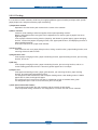
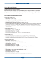
2.2.3.2 SMPS & HVPS board
7KH6036VXSSOLHV'&3RZHUWRWKH6\VWHP
,WWDNHV99DQGRXWSXWVWKH99WRVXSSO\WKHSRZHUWRWKHPDLQERDUGDQGDOORWKHUERDUGV
7KH+936ERDUGFUHDWHVWKHKLJKYROWDJHRI7+90+96XSSO\'HYDQGVXSSOLHVLWWRWKHGHYHORSHUSDUWIRU
PDNLQJEHVWFRQGLWLRQWRGLVSOD\WKHLPDJH7KH+936SDUWWDNHVWKH9DQGRXWSXWVWKHKLJKYROWDJHIRU
7+90+9%,$6DQGWKHRXWSXWWHGKLJKYROWDJHLVVXSSOLHGWRWKHWRQHU23&FDUWULGJHDQGWUDQVIHUUROOHU
2.2.3.2(a) HVPS (High Voltage Power Supply)
7UDQVIHU+LJK9ROWDJH7+9
Ƒ,QSXW9ROWDJH9'&
Ƒ2XWSXW9ROWDJH0$;.9'XW\9DULDEOH
Ƒ/LQH5HJXODWLRQXQGHUÀXFWXDWLRQLQSXW9a9
Ƒ2XWSXW9ROWDJH5LVLQJ7LPHPV0D[
Ƒ2XWSXW9ROWDJH)DOOLQJ7LPHPV0D[
Ƒ)OXFWXDWLQJWUDQVIHUYROWDJHZLWKHQYLURQPHQWDOYDULRXV9a.9
Ƒ(QYLURQPHQW5HFRJQLWLRQ&RQWURO0HWKRG7KH7+93:0$&7,9(LVWUDQVIHUDFWLYHVLJQDO,WGHWHFWVWKH
UHVLVWDQFHE\UHFRJQL]LQJWKHYROWDJHYDOXH)%ZKLOHSHUPLWVWKHHQYLURQPHQWDOUHFRJQLWLRQYROWDJH
Ƒ2XWSXW9ROWDJH&RQWURO0HWKRG7UDQVIHU2XWSXW9ROWDJHLVRXWSXWWHGDQGFRQWUROOHGE\FKDQJLQJ'XW\RI
7+93:06LJQDO
&KDUJH9ROWDJH0+9
Ƒ,QSXW9ROWDJH9'&
Ƒ2XWSXW9ROWDJH.9a.9'&
Ƒ2XWSXW9ROWDJH5LVLQJ7LPHPV0D[
Ƒ2XWSXW9ROWDJH)DOOLQJ7LPHPV0D[
Ƒ2XWSXW&RQWURO6LJQDO0+93:0&38LV+9RXWSXWZKHQ3:0LV/RZ
&OHDQLQJ9ROWDJH7+9
Ƒ.9
Ƒ7KH7UDQVIHU9ROWDJHLVQRWRXWSXWWHGEHFDXVHWKH7+93:0LVFRQWUROOHGZLWKKLJK
Ƒ7KH7UDQVIHU9ROWDJHLVRXWSXWWHGEHFDXVHWKH7+9(QDEOH6LJQDOLVFRQWUROOHGZLWKORZ
Ƒ7KHRXWSXWÀXFWXDWLRQUDQJHLVELJEHFDXVHWKHUHLVQR)HHGEDFNFRQWUROFRQQHFWLRQ5HVLVWRU
'HYHORSLQJ9ROWDJH'(9
Ƒ,QSXW9ROWDJH9'&
Ƒ2XWSXW9ROWDJH9a9'&
Ƒ2XWSXW9ROWDJH)OXFWXDWLRQ0HWKRG3:0&RQWURO
Ƒ/LQH5HJXODWLRQXQGHUÀXFWXDWLRQLQSXW9a9
Ƒ/RDG5HJXODWLRQ8QGHU
Ƒ2XWSXW9ROWDJH5LVLQJ7LPHPV0D[
Ƒ2XWSXW9ROWDJH)DOOLQJ7LPHPV0D[
Ƒ2XWSXW&RQWURO6LJQDO%,$63:0WKH&38RXWSXWLV+9RXWSXWZKHQ3:0LVORZ
6XSSO\
Ƒ2XWSXW9ROWDJH9a9'&=(1(5XVLQJ'(9
Ƒ/LQH5HJXODWLRQXQGHUÀXFWXDWLRQLQSXW9a9
Ƒ/RDG5HJXODWLRQ8QGHU
Ƒ2XWSXW9ROWDJH5LVLQJ7LPHPV0D[
Ƒ2XWSXW9ROWDJH)DOOLQJ7LPHPV0D[
Ƒ2XWSXW&RQWURO6LJQDO%,$63:0WKH&38LV+9RXWSXWZKHQ3:0LVORZ
Service Manual
Samsung Electronics
Product spec and feature
&11
&11
0DLQ3%$&21
0DLQ3%$&21
SW2
SW2
5HDU&RYHU
5HDU&RYHU
2SHQ6ZLWFK
2SHQ6ZLWFK
SW1
SW1
)URQt
)URQt-&RYHU
-&RYHU
2SHQ6ZLWFK
2SHQ6ZLWFK
0+9
0+9
DE9
DE9
OP&
OP&
6833/<
6833/<
7+9
7+9
9$5,6725
9$5,6725
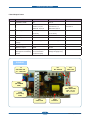
2.2.3.2(b) SMPS (Switching Mode Power Supply)
,WLVWKHSRZHUVRXUFHRIHQWLUHV\VWHP,WLVDVVHPEOHGE\DQLQGHSHQGHQWPRGXOHVRLWLVSRVVLEOHWRXVH
IRUFRPPRQXVH,WLVPRXQWHGDWWKHVLGHRIWKHVHW,WLVFRQVLVWHGRIWKH6036SDUWZKLFKVXSSOLHVWKH'&
SRZHUIRUGULYLQJWKHV\VWHPDQGWKH$&KHDWHUFRQWUROSDUWZKLFKVXSSOLHVWKHSRZHUWRIXVHU6036KDV
WZRRXWSXWFKDQQHOV:KLFKDUH9DQG9
$&,QSXW
Ƒ,QSXW5DWHG9ROWDJH$&9a9$&9a9
Ƒ,QSXW9ROWDJHÀXFWXDWLQJUDQJH$&9a9$&9a9
Ƒ5DWHG)UHTXHQF\+]
Ƒ)UHTXHQF\)OXFWXDWLQJUDQJHa+]
Ƒ,QSXW&XUUHQW8QGHU$UPV$UPV%XWWKHVWDWXVZKHQODPSLVRIIRUUDWHGYROWDJHLVLQSXWWHG
RXWSXWWHG
Service Manual
Samsung Electronics
Product spec and feature
5DWHG2XWSXW3RZHU
NO
ITEM
CH1
CH2
Remark
1
&+$11(/1$0(
9
9
2
&211(&7253,1
&21
&21
&21
93,1
93,1
963,1
*1'3,1
*1'3,1
SUNGHO
5DWHG2XWSXW
9
9
a9
a9
1RU2XWSXW&XUUHQW
$
$
0D[2XWSXW&XUUHQW
$
$
5,33/(12,6(
8QGHUP9SS
8QGHUP9SS
9ROWDJH
1RUPDORXWSXW
:
:
0D[LPXPRXWSXW
:
:
Protection for loading
6KXWGRZQ(2.5~5.0A)
6KXWGRZQ$a5$RU
VKRUWDJHDQGRYHUÀRZLQJ or Fuse Protection
current
9ROWDJH'URSWULS
8QGHU/36VSHF
SUNGHO
F71
F71
SH:
SH: 250V
250V 2A
2A
F1
F1
V2C:
250V
V2C: 250V 8A
8A
V1
V1 :: 250V
250V 10A
10A
F72
F72
250V
250V 2.5A
2.5A
CON1
CON1
(AC
(AC POWER
POWER
CON.)
CON.)
CON3
CON3
(Main
(Main PBA
PBA CON.)
CON.)
24V
24V :: 33 55 77 99
5V
5V :: 11
11 13
13 15
15
CON2
CON2
(Heat
(Heat Lamp
Lamp
CON.)
CON.)
PC22
PC22
TLP3061F
TLP3061F
F02
F02
250V
250V 3.15A
3.15A
Service Manual
2-21
Samsung Electronics
Product spec and feature
SEM
F71
F71
SH:
SH: 250V
250V
4A
4A
F1
F1
V2C:
V2C: 250V
250V 8A
8A
V1
V1 :: 250V
250V 10A
10A
CON1
CON1
(AC
(AC POWER
POWER
CON.)
CON.)
F72
F72
250V
250V 4A
4A
CON4
CON4
(Main
(Main PBA
PBA
CON.)
CON.)
24V
24V :: 33 55 77 99
5V
5V :: 11
11 13
13 15
15
CON2
CON2
(Heat
(Heat
Lamp
Lamp
CON.)
CON.)
F02
F02
250V
250V 3.15A
3.15A
PC51
PC51
TLP3061F
TLP3061F
2.2.3.2(c) FUSER AC POWER CONTROL
)XVHU+($7/$03JHWVKHDWIURP$&SRZHU7KH9$SRZHUFRQWUROVWKHVZLWFKZLWKWKH7ULDFD
VHPLFRQGXFWRUVZLWFK7KHµ212))FRQWURO¶LVRSHUDWHGZKHQWKHJDWHRIWKH7ULDFLVWXUQHGRQRIIE\
3KRWRWULDFLQVXOWLQJSDUW,QRWKHUZRUGVWKH$&FRQWUROSDUWLVSDVVLYHFLUFXLWVRLWWXUQVWKHKHDWHURQRII
ZLWKWDNLQJVLJQDOIURPHQJLQHFRQWUROSDUW
:KHQWKHµ+($7(521¶VLJQDOLVWXUQHGRQDWHQJLQHWKH/('RI3&3KRWR7ULDFWDNHVWKHYROWDJH
DQGÀDVKHV)URPWKHÀDVKLQJOLJKWWKH7ULDFSDUWOLJKWUHFHLYLQJSDUWWDNHVWKHYROWDJHDQGWKHYROWDJHLV
VXSSOLHGWRWKHJDWHRI7ULDFDQGÀRZVLQWRWKH7ULDF$VDUHVXOWWKH$&FXUUHQWÀRZVLQWKHKHDWODPSDQG
KHDWLVRFFXUUHG2QWKHRWKHUKDQGZKHQWKHVLJQDOLVRIIWKH3&LVRIIWKHYROWDJHLVFXWRIIDWWKHJDWH
RI7ULDFWKH7ULDFEHFRPHVRIIDQGWKHQWKHKHDWODPSLVWXUQHGRII
7ULDF4IHDWXUH$/9PRGHO$+9PRGHO96:,7&+,1*
3KRWRWULDF&RXSOHU3&
Ƒ7XUQ2Q,I&XUUHQWP$aP$'HVLJQP$
Ƒ+LJK5HSHWLYH3HDN2II6WDWH9ROWDJH0LQ9
Service Manual
2-22
Samsung Electronics
Product spec and feature
2.2.3.3 Fax
,PSOHPHQWHGE\EDVHGRQ&RQH[DQW'$$'DWD$FFHVV$UUDQJHPHQW6ROXWLRQDQGLVURXJKO\FRPSRVHGRI
WZRNLQGV&KLS6ROXWLRQ
&;6);([LVWLQJ0RGHP&KLSZKLFKDGGV66'6\VWHP6LGH'HYLFHIRULQWHUIDFLQJEHWZHHQ
/6'DQG',%RI)03OXV&RUH
&;/6'/,8/LQH,QWHUIDFH8QLW&KLSZKLFKLVFRQWUROOHGE\66'DQGVDWLV¿HVHDFK3671
5HTXLUHPHQWVE\PRGXODWLQJLQWHUQDO&RQ¿JXUDWLRQZLWKFRQQHFWLQJ7HO/LQH
Service Manual
Samsung Electronics
Product spec and feature
2.2.3.4 Scan
3LFWRULDOVLJQDOLQSXWSDUWRXWSXWVLJQDORI&,6SDVVHVWKURXJK03&DSFKDQJHWR$'&DW+79DQG
GH¿QHGVLJQDOEHWZHHQ+79DQG&+2586SURFHVVHVWKH,PDJHVLJQDO:KHQ$)(DFFHSWHDFK
SL[HO6+$6DPSOHDQG+ROG$PSOL¿HUWHFKQLTXHZKLFKVDPSOHVDUPOHYHORQFHLVXVHGRQHDFKSL[HOE\
&,6VLJQDO
3LFWRULDOLPDJHSURFHVVLQJSDUWUHDG&,63L[HOGDWDLQWHUPVRIGSL/LQHDQGSURFHVV(UURU'LIIXVLRQ
$OJRULWKPWH[W0L[HGPRGHGLWKHUSKRWRPRGHDQGWKHQVWRUH'DWDDW6FDQ%XIIHURQ3&6FDQ
PRGHZLWKRXWDOJRULWKP
2QHYHU\PRGH6KDGLQJ&RUUHFWLRQDQG*DPPD&RUUHFWLRQDUHH[HFXWHGDKHDGWKHQSURFHVVLQJLV
H[HFXWHGODWHU
6FDQ,PDJH&RQWURO6SHFL¿FDWLRQ
Η6FDQ/LQH7LPHPVHFFK
Θ6FDQ5HVROXWLRQ0D['3,
Ι6FDQ:LGWKPP
Κ main function
,QWHUQDOELW$'&
:KLWH6KDGLQJ&RUUHFWLRQ
*DPPD&RUUHFWLRQ
&,6,QWHUIDFH
&,62SHUDWLQJ3DUW&,6,PDJHVHQVRUXVH9
&,60D[LPXP2SHUDWLQJ)UHTXHQF\0+]
&,6/LQHWLPHPVHFFK
:KLWH'DWDRXWSXW9ROWDJH990RQR&RS\PVOLQH
Service Manual
Samsung Electronics
Product spec and feature
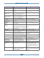
2.2.3.5 Engine F/W
2.2.3.5(a) Control Algorithm
)HHGLQJ
,IIHHGLQJIURPDFDVVHWWHWKHGULYHRIWKHSLFNXSUROOHULVFRQWUROOHGE\FRQWUROOLQJWKHVROHQRLG7KHRQ
RIIRIWKHVROHQRLGLVFRQWUROOHGE\FRQWUROOLQJWKHJHQHUDORXWSXWSRUWRUWKHH[WHUQDORXWSXWSRUW,IIHHGLQJ
IURPDPDQXDOIHHGHUGHFLGHWRLQVHUWWKHSDSHUDFFRUGLQJWRWKHRSHUDWLRQRIWKH5HJLVHQVRUDQGE\
GULYLQJWKHPDLQPRWRULQVHUWWKHSDSHULQIURQWRIWKHIHHGVHQVRU:KLOHSDSHUPRYHVRFFXUUHQFHRI-DP
LVMXGJHGDVEHORZ
Item
Description
-$0
$IWHUSLFNLQJXSSDSHUFDQQRWEHHQWHUHGGXHWRSDSHULVQRWIHG
$IWHUSLFNLQJXSSDSHUHQWHUHGEXWLWFDQQRWUHDFKWRWKHIHHGVHQVRULQFHUWDLQWLPHGXHWR
VOLSHWF
$IWHUSLFNLQJXSLIWKHIHHGVHQVRULVQRWRQUHSLFNXS$IWHUUHSLFNLQJXSLIWKHIHHG
VHQVRULVQRWRQDIWHUFHUWDLQWLPHLWLV-$0
,WLVDVWDWXVWKDWWKHOHDGLQJHGJHRIWKHSDSHUGRHVQ¶WSDVVWKHIHHGVHQVRU
(YHQWKRXJKWKHSDSHUUHDFKHVWRWKHIHHGVHQVRUWKHIHHGVHQVRUGRHVQ¶WEH21
,WLVDVWDWXVWKDWWKHOHDGLQJHGJHRIWKHSDSHUDOUHDG\SDVVHVWKHIHHGVHQVRU
-$0
$IWHUWKHOHDGLQJHGJHRIWKHSDSHUSDVVHVWKHIHHGVHQVRUWKHWUDLOLQJHGJHRIWKHSDSHU
FDQQRWSDVVWKHIHHGVHQVRUDIWHUDFHUWDLQWLPH7KHIHHGVHQVRUFDQQRWEH2))
$IWHUWKHOHDGLQJHGJHRIWKHSDSHUSDVVHVWKHIHHGVHQVRUWKHSDSHUFDQQRWUHDFKWKHH[LW
VHQVRUDIWHUFHUWDLQWLPH7KHH[LWVHQVRUFDQQRWEH21
7KHSDSHUH[LVWVEHWZHHQWKHIHHGVHQVRUDQGWKHH[LWVHQVRU
-$0
$IWHUWKHWUDLOLQJHGJHRIWKHSDSHUSDVVHVWKHIHHGVHQVRUWKHSDSHUFDQQRWSDVVWKHH[LW
VHQVRUDIWHUFHUWDLQWLPH
'83/(;
-$0
$IWHUWKHWUDLOLQJHGJHRIWKHSDSHUSDVVHVWKHH[LWVHQVRUWKHOHDGLQJHGJHRIWKHSDSHU
FDQQRWUHDFKWKH'XSOH[-DP6HQVRUDIWHUFHUWDLQWLPH
'83/(;
-$0
$IWHUWKHOHDGLQJHGJHRIWKHSDSHUSDVVHVWKH5HJLVHQVRUWKHOHDGLQJHGJHRIWKHSDSHU
FDQQRWUHDFKWKHIHHGVHQVRUDIWHUFHUWDLQWLPH
2.2.3.5(b) Driver
\JHDULQJWKHPDLQPRWRUGULYHVWKHUROOHUVVXFKDVIHHGLQJUROOHUGHYHORSLQJUROOHUIXVHUUROOHUDQGH[LWLQJ
%
UROOHU7KH%/'&PRWRULVFRQWUROOHGIRUWKHVXFKDFFHOHUDWLRQVHFWLRQDQGVWHDG\VHFWLRQ
7KH%/'&PDLQPRWRULVRSHUDWHGE\WKH%/'&FORFNDQGWKHHQDEOHVLJQDO
2.2.3.5(c) Transfer
7KHFKDUJLQJYROWDJHGHYHORSLQJYROWDJHDQGWKHWUDQVIHUYROWDJHDUHFRQWUROOHGE\3:03XOVH:LGWK
0RGXODWLRQ7KHHDFKRXWSXWYROWDJHLVFKDQJHDEOHGXHWRWKH3:0GXW\7KHWUDQVIHUYROWDJHDGPLWWHG
ZKHQWKHSDSHUSDVVHVWKHWUDQVIHUUROOHULVGHFLGHGE\HQYLURQPHQWUHFRJQLWLRQ7KHUHVLVWDQFHYDOXHRIWKH
WUDQVIHUUROOHULVFKDQJHGGXHWRWKHVXUURXQGLQJHQYLURQPHQWRUWKHHQYLURQPHQWRIWKHVHWDQGWKHYROWDJH
YDOXHZKLFKFKDQJHVGXHWRWKHHQYLURQPHQWVLVFKDQJHGWKURXJK$'FRQYHUWHU7KHYROWDJHYDOXHIRU
LPSUHVVLQJWRWKHWUDQVIHUUROOHULVGHFLGHGE\WKHFKDQJHGYDOXH(DFKYROWDJHYDOXHLVFRQWUROOHGDFFRUGLQJ
WR7LPLQJ&KDUW
Service Manual
Samsung Electronics
Product spec and feature
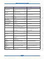
2.2.3.5(d) Fusing
7KHWHPSHUDWXUHFKDQJHRIWKHKHDWUROOHUVVXUIDFHLVFKDQJHGWRWKHUHVLVWDQFHYDOXHWKURXJKWKH
WKHUPLVWRU
%\FRQYHUWLQJWKHYROWDJHYDOXHZKLFKLPSUHVVHGWRWKHUHVLVWDQFHWRWKHGLJLWDOYDOXHWKURXJKWKH$'
FRQYHUWHUWKHWHPSHUDWXUHLVGHFLGHG7KH$&SRZHULVFRQWUROOHUE\FRPSDULQJWKHWDUJHWWHPSHUDWXUHWR
WKHYDOXHIURPWKHWKHUPLVWRU,IWKHYDOXHIURPWKHWKHUPLVWRULVRXWRIFRQWUROOLQJUDQJHZKLOHFRQWUROOLQJWKH
IXVLQJWKHHUURUVWDWHGLQWKHEHORZWDEOHRFFXUV
/DPS0HWKRG
Error
Description
23(1+($7(5525
:KHQZDUPLQJXSLWKDVEHHQORZHUWKDQRYHUVHFRQGV
/2:+($7(5525
6WDQGE\KDVEHHQORZHUWKDQWKH6WDQGE\5HIHUHQFH7HPSHUDWXUHRYHU
VHFRQGV
3ULQWLQJKDVEHHQORZHUWKDQWKH3ULQWLQJ5HIHUHQFH7HPSHUDWXUHRYHU
VHFRQGV
:KHQ:DUP8S(QG3URFHVVLWKDYHEHHQORZHUWKDQWKH:DUP8S5HIHUHQFH
7HPSHUDWXUHRYHUVHFRQGV
29(5+($7(5525
,WKDVEHHQKLJKHUWKDQRYHUVHFRQGV
,WKDVEHHQKLJKHUWKDQRYHUVHFRQGV
,WKDVEHHQKLJKHUWKDQWKH6WDQGE\5HIHUHQFH7HPSHUDWXUHRYHU
VHFRQGV
!7KLVFDQEHFKDQJHGLQWKHIXWXUH
2.2.3.5(e) LSU
7KH/68LVFRQVLVWHGRIWKH/'/DVHU'LRGHDQGWKHSRO\JRQPRWRUFRQWURO:KHQWKHSULQWLQJVLJQDO
RFFXUVLWWXUQVRQWKH/'DQGGULYHVWKHSRO\JRQPRWRU:KHQWKHGHWHFWRUGHWHFWVWKHEHDP+V\QFRFFXUV
:KHQWKHSRO\JRQPRWRUVSHHGEHFRPHVVWUDG\/UHDG\RFFXUV,IWZRFRQGLWLRQVDUHVDWLV¿HGWKHVWDWXVDUH
QRWVDWLV¿HGWKHHUURUVKRZQLQEHORZRFFXUV
Error
Description
Polygon Motor Error
:KHQWKHSRO\JRQPRWRUVSHHGGRHVQWEHFRPHVWHDG\
+V\QF(UURU
7KHSRO\JRQPRWRUVSHHGLVVWHDG\EXWWKH+V\QFLVQRWJHQHUDWHG
Service Manual
Samsung Electronics
Product spec and feature
2.2.4 S/W Descriptions
2.2.4.1 Overview
7KHVRIWZDUHRI6&;[VHULHVV\VWHPLVFRQVWUXFWHGZLWK
+RVW6RIWZDUHSDUWWKDWWKHDSSOLFDWLRQVRIWZDUHRSHUDWHGLQ:LQGRZDQG:HE(QYLURQPHQWDQG
)LUPZDUHSDUWVWKDWLVD(PEHGGHGVRIWZDUHFRQWUROVSULQWLQJMRE
2.2.4.2 Architecture
Host Software is made up of
*UDSKLF8VHU,QWHUIDFHWKDWRIIHUVWKHYDULRXVHGLWLQJIXQFWLRQVWRXVHULQ+RVW
'ULYHUWKDWWUDQVODWHVWKHUHFHLYHGGRFXPHQWWRD3ULQWLQJ&RPPDQGODQJXDJHZKLFKSULQWHUFDQ
XQGHUVWDQGDQGWUDQVIHUVGDWDWRVSRROHU
6WDQGDORQH$SSOLFDWLRQWKDWRIIHUVWKHYDULRXVSULQWLQJDSSOLFDWLRQ3683ULQWHU6HWWLQJV8WLOLW\3ULQWHU
6WDWXV0RQLWRU1HWZRUN0DQDJHPHQWLQ:LQGRZV\VWHP
:HEEDVHG$SSOLFDWLRQWKDWRIIHUVWKHVDPHIXQFWLRQVDV6WDQGDORQH$SSOLFDWLRQDQG5'&5HPRWH
'LDJQRVLV&RQWUROLQ:HEHQYLURQPHQW
Firmware is made up of
$SSOLFDWLRQ(PXODWLRQWKDWLVDLQWHUSUHWHUWUDQVODWHGDWDUHFHLYHGIURP+RVWWRDSULQWLQJODQJXDJH3&/
36*',RQO\6&;)1HWFWREHDEOHWRPDNHWKHXVHUWRWDNHVDPHRXWSXWDVRULJLQDOO\RQHZKDW
FRPSRVHGLQ+RVW
.HUQHOWKDWFRQWURODQGPDQDJHPHQWWKHZKROHSURFHGXUHLQFOXGHRI&RQWUROÀRZDQG3ULQWLQJ-REEHIRUH
WUDQVIHUWR(QJLQHV\VWHP
Service Manual
Samsung Electronics
Product spec and feature
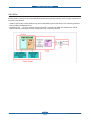
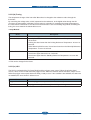
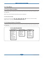
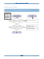
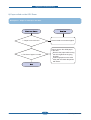
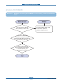
2.2.4.3 Data and Control Flow
*',RQO\6&;)1
3&/3&/;/
The above Block Diagram is explained that:
Host Side is made up of
'ULYHUWKDWLV:LQGRZVDSSOLFDWLRQVRIWZDUHWUDQVODWHSULQWHGGDWDWRRQHRISULQWHUODQJXDJHDQGFUHDWH
VSRROHU¿OH
:HEEDVHG$SSOLFDWLRQWKDWRIIHUDYDULRXVSULQWHUDGGLWLRQDOIXQFWLRQVPDQDJHPHQWRISULQWLQJMRE
SULQWHUDGPLQLVWUDWLRQ6WDWXVPRQLWRUWRPRQLWRULQJWKHSULQWHUVWDWXVE\UHDOWLPHLQ:HELQGHSHQGHQW
HQYLURQPHQWRQ26
6WDQGDORQH$SSOLFDWLRQWKDWLVDVLPLODU:LQGRZVRIWZDUHDVVDPHDVDERYH
3RUW0RQLWRUWKDWPDQDJHVWKHQHWZRUNFRPPXQLFDWLRQEHWZHHQVSRROHUDQG1HWZRUN,QWHUIDFH&DUGRU
YDULRXVDGGLWLRQDODSSOLFDWLRQDQG1HWZRUN,QWHUIDFH&DUGWKLVLVDW¿UVWPDNHFRPPXQLFDWLRQORJLFDO
SRUWPDQDJHWKHGDWDWUDQVIHUWKHPIURPVSRROHUWRQHWZRUNSRUWDQGRIIHUWKHUHVXOWRISULQWLQJ
Service Manual
Samsung Electronics
Product spec and feature
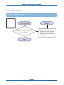
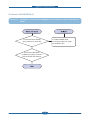
Firmware Side is made up of
1HWZRUN,QWHUIDFH&DUGLVWKDWUHOD\WKHFRPPXQLFDWLRQEHWZHHQ+RVWDQGNHUQHOXVLQJYDULRXVQHWZRUN
SURWRFRO
.HUQHOLVWKDWPDQDJHVWKHÀRZFRQWURORIHPXODWLRQSURFHGXUHUHFHLYLQJGDWDIURP+RVWRU1HWZRUNFDUG
DQGSULQWLQJZLWKHQJLQHUHQGHULQJMRE
(PXODWLRQLVWKDWLQWHUSUHWVWKHYDULRXVRXWSXWGDWDIURPVHOHFWHGHPXODWLRQ
(QJLQHLVWKDWSULQWVUHQGHUHGELWPDSGDWDWRSDSHUZLWKUHTXLUHGVL]HDQGW\SHE\.HUQHO
$QGWKHQIRU-RE6SRROLQJIXQFWLRQIRU0XOWL8VHU0XOWL3ULQWLQJWKDWLVRFFXUUHGLQ1HWZRUNSULQWLQJDQG
YDULRXVDGGLWLRQDOSULQWLQJIXQFWLRQVWKLV.HUQHOXVHPD[4XHXLQJV\VWHPVLQDPHPRU\
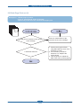
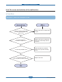
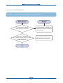
In Printing, the two procedures are
&DVHRIXVLQJ86%3RUW
$IWHUXVHUVWDUWWRSULQWWKHZDQWHGGRFXPHQWWR3&/VWULQJRUFRPSUHVVHG*',ELWPDSGDWD'ULYHU
WUDQVODWHWKHDOOJUDSKLFGDWDRILWDQGVHQGGDWDWRKRVWVSRROHU$QGWKHQWKHVSRROHUVHQGVWKHGDWD
VWUHDPWRWKHSULQWHUYLD86%SRUW
.HUQHOUHFHLYHVWKLVGDWDIURP+RVWDQGWKHQVHOHFWHPXODWLRQ¿WWRGDWDDQGVWDUWVHOHFWHGRQH$IWHU
HPXODWLRQMREHQG.HUQHOVHQGVWKHRXWSXWELWPDSGDWDWR(QJLQHXVLQJ3ULQWHU9LGHR&RQWUROOHUE\
FORFNW\SHIRU/68
(QJLQHSULQWWKHUHFHLYHGGDWDWRUHTXLUHGSDSHUZLWKWKHVHTXHQWLDOGHYHORSLQJSURFHVV
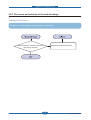
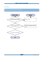
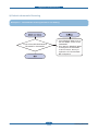
&DVHRIXVLQJ1HWZRUN,QWHUIDFH&DUG
$IWHUXVHUVWDUWWRSULQWWKHZDQWHGGRFXPHQWWR3&/VWULQJRUFRPSUHVVHG*',ELWPDSGDWD'ULYHU
WUDQVODWHWKHDOOJUDSKLFGDWDRILWDQGVHQGGDWDWRKRVWVSRROHU
,IVR3RUWPRQLWRUPDQDJLQJQHWZRUNSRUWUHFHLYHVGDWDIURPVSRROHUDQGVHQGVDGDWDVWUHDPWRWKH
1HWZRUN,QWHUIDFH&DUG
1HWZRUNLQWHUIDFHFDUGUHFHLYHVLWDQGVHQGWR.HUQHOSDUW
.HUQHOUHFHLYHVWKLVGDWDIURP+RVWDQGWKHQVHOHFWHPXODWLRQ¿WWRGDWDDQGVWDUWVHOHFWHGRQH$IWHU
HPXODWLRQMREHQG.HUQHOVHQGVWKHRXWSXWELWPDSGDWDWR(QJLQHXVLQJ3ULQWHU9LGHR&RQWUROOHUE\
FORFNW\SHIRU/68
(QJLQHSULQWWKHUHFHLYHGGDWDWRUHTXLUHGSDSHUZLWKWKHVHTXHQWLDOGHYHORSLQJSURFHVV
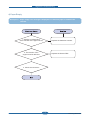
The additional printing function are realized in
:HEHQYLURQPHQW
:LQGRZHQYLURQPHQW
2QDGGLWLRQ.HUQHOLQIRUPVDVWDWXVRISULQWLQJVWDWXVDQGSULQWHUVWDWXVWRXVHUPDGHSULQWLQJMREZLWKWKH
6WDWXV0RQLWRU
Service Manual
Samsung Electronics
Disassembly and Reassembly
3. Disassembly and Reassembly
3.1 General Precautions on Disassembly
Releasing Plastic Latches
When you disassemble and reassemble
components, you must use extreme caution. The
close proximity of cables to moving parts makes
proper routing a must.
If components are removed, any cables disturbed
by the procedure must be restored as close as
possible to their original positions. Before removing
any component from the machine, note the cable
routing that will be affected.
Many of the parts are held in place with plastic
latches. The latches break easily; release them
carefully.
To remove such parts, press the hook end of the
latch away from the part to which it is latched.
Whenever servicing the machine, you
must perform as follows:
1. Check to verify that documents are not stored in
memory.
2. Be sure to remove the toner cartridge before you
disassemble parts.
3. Unplug the power cord.
4. Use a flat and clean surface.
5. Replace only with authorized components.
6. Do not force plastic-material components.
7. Make sure all components are in their proper
position.
Service Manual
3-1
Samsung Electronics
Disassembly and Reassembly
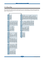
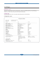
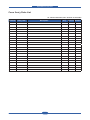
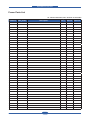
3.1.1 Screws used in the printer
SEC_CODE
Description
Qty
SCREW-TAPPING;PWH,+,-,2,M3,L8,ZPC(BLK),SWRCH18A,-
1
SCREW-TAPTITE;PWH,+,B,M3,L10,NI PLT,SWRCH18A
3
6003-000282 CARTRIDGE-TONER
SCREW-TAPTITE;BH,+,-,B,M3,L8,ZPC(BLK),SWRCH18A,-
10
6003-000196 ELA HOU-SCAN_HIGH
SCREW-TAPTITE;PWH,+,B,M3,L10,NI PLT,SWRCH18A
10
6003-000269 ELA HOU-ADF MOTOR
SCREW-TAPTITE;BH,+,-,S,M3,L6,ZPC(WHT),SWRCH18A,-
3
6003-000196 ELA HOU-ADF LOWER
SCREW-TAPTITE;PWH,+,B,M3,L10,NI PLT,SWRCH18A
6
6003-000196 MEA-COVER PLATEN
SCREW-TAPTITE;PWH,+,B,M3,L10,NI PLT,SWRCH18A
6
6003-000196 ELA HOU-OPE
SCREW-TAPTITE;PWH,+,B,M3,L10,NI PLT,SWRCH18A
4
6003-000196 ELA HOU-PLATEN_HIGH
SCREW-TAPTITE;PWH,+,B,M3,L10,NI PLT,SWRCH18A
4
6003-000196 ELA HOU-SCAN LOWER_H
SCREW-TAPTITE;PWH,+,B,M3,L10,NI PLT,SWRCH18A
9
6003-000196 ELA UNIT-STANDARD SCAN
SCREW-TAPTITE;PWH,+,B,M3,L10,NI PLT,SWRCH18A
3
6003-000269 ELA UNIT-SCAN DRIVE
SCREW-TAPTITE;BH,+,-,S,M3,L6,ZPC(WHT),SWRCH18A,-
2
6002-000440
SCREW-TAPPING;PWH,+,-,2,M3,L8,ZPC(BLK),SWRCH18A,-
13
6003-000196
SCREW-TAPTITE;PWH,+,B,M3,L10,NI PLT,SWRCH18A
64
6003-000301 ELA HOU-FRAME
SCREW-TAPTITE;BH,+,-,S,M4,L6,ZPC(WHT),SWRCH18A,-
1
6002-000440
6003-000196
Location
Duplex Unit
SCREW-TAPTITE;PH,+,WSP,B,M3,L10,ZPC(WHT),
6006-001078
SWRCH18A,-
1
6003-000269 ELA UNIT-DRIVE
SCREW-TAPTITE;BH,+,-,S,M3,L6,ZPC(WHT),SWRCH18A,-
11
6003-000196
SCREW-TAPTITE;PWH,+,B,M3,L10,NI PLT,SWRCH18A
3
SCREW-TAPTITE;BH,+,-,B,M3,L8,ZPC(BLK),SWRCH18A,-
4
6003-000282 MEA-COVER FRONT
SCREW-TAPTITE;BH,+,-,B,M3,L8,ZPC(BLK),SWRCH18A,-
1
6003-000196
SCREW-TAPTITE;PWH,+,B,M3,L10,NI PLT,SWRCH18A
14
SCREW-TAPTITE;BH,+,B,M4,L10,NI PLT,SWRCH18A
4
6003-000282 ELA UNIT-LSU
SCREW-TAPTITE;BH,+,-,B,M3,L8,ZPC(BLK),SWRCH18A,-
10
6003-000282 ELA UNIT-LSU LD
SCREW-TAPTITE;BH,+,-,B,M3,L8,ZPC(BLK),SWRCH18A,-
2
6003-000196
SCREW-TAPTITE;PWH,+,B,M3,L10,NI PLT,SWRCH18A
2
6003-000261 MEA UNIT-CASSETTE
SCREW-TAPTITE;BH,+,-,B,M3,L6,ZPC(WHT),SWRCH18A,-
1
6003-000264
SCREW-TAPTITE;PWH,+,-,B,M3,L6,ZPC(WHT),SWRCH18A,-
1
6003-000282
6003-001256
Service Manual
ELA UNIT-FUSER
ELA HOU-MAIN LINE
3-2
Samsung Electronics
Disassembly and Reassembly
3.2 General Disassembly
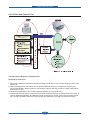
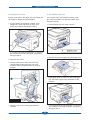
3.2.1 Front Cover
1. Open the front cover after take out the cassette.
2. Separate the front cover from the lock the frame
by pulling the front cover to the direction of
arrow.
3.2.2 Rear Cover
1. Remove the Duplex unit.
Service Manual
2. Open the rear cover. And separate the rear
cover from the locking by pulling the rear cover
to the direction of arrow.
3-3
Samsung Electronics
Disassembly and Reassembly
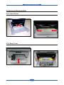
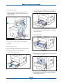
3.2.3 Right/Left Cover
1. Remove the one screw. And pull and release the
right cover somewhat.
3. Pull the left cover to the direction of arrow and
release it.
2. Release the right cover after unplug the 1
connector from Main PBA.
Service Manual
3-4
Samsung Electronics
Disassembly and Reassembly
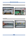
3.2.4 Scan and ADF Assy
1. Remove the 2 screws after remove the right
cover.
2. Remove the one screw and connected harness
from Main board. And lift the Scan Assy to the
direction of arrow.
3.2.4.1 ADF Unit
1. Unplug the harness after remove the cap
harness as shown below.
Service Manual
2. Lift up and release the ADF Assy.
3-5
Samsung Electronics
Disassembly and Reassembly
3.2.4.2 Stacker TX
1. Remove the 2 screws from the bottom of ADF
Assy.
Service Manual
2. Lift up and release the Stacker TX
3-6
Samsung Electronics
Disassembly and Reassembly
3.2.4.3 ADF Engine unit
1. Open the ADF cover and remove it. And remove the pick-up roller by following below sequence.
2
3
1
Locking
2. Remove the ADF engine unit after remove the 2
screws from the bottom of SET.
Service Manual
3. Remove the 2 screws of the ADF cover upper.
And then lift it up.
3-7
Samsung Electronics
Disassembly and Reassembly
3.2.4.4 OPE Unit
1. Pull up the OPE unit.
2. Remove the 2 connector and release the OPE
unit.
Hook
3.2.4.5 CIS Unit
1. Remove the 4 screws of the Scan upper.
Service Manual
2. Remove the 4 screw and 1 CIS cable. And
release the CIS unit.
3-8
Samsung Electronics
Disassembly and Reassembly
3.2.5 Middle Cover
1. Remove the 2 screws as shown below.
2. Remove the 2 screws from the front and rear of
the SET. Unplug the harness connected to the
main board. And lift the middle cover up.
3.2.6 Fuser
1. Remove the rear cover. Remove the Guide rear
by pushing both side and removing the hinge.
2. Remove the 4 screw. And remove the fuser after
remove the connector.
CAUTION
The fuser is very hot. So turn the printer off
and wait until the printer to cool before
replacing it.
Service Manual
3-9
Samsung Electronics
Disassembly and Reassembly
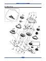
3.2.7 LSU
1. Release the LSU after remove the 4 screws and one connector.
3.2.8 Main Drive Assy
- Before disassembly, remove the cassette, Cover front, Cover left, Cover rear.
1. Remove the rear cover. Remove the Guide rear
by pushing both side and removing the hinge.
Service Manual
2. Remove the 4 screw. And remove the fuser after
remove the connector.
3-10
Samsung Electronics
Disassembly and Reassembly
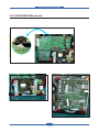
3.2.9 HVPS/SMPS/Main board
- Before disassembly, remove the cover front, cover rear, cover rigth.
1. Release the HVPS board after remove the 6 screws and 1 connector.
2. Release the SMPS board after remove the 4
screws and 2 connector.
Service Manual
3. Release the Main board after remove the 4
screws and all harness.
3-11
Samsung Electronics
Disassembly and Reassembly
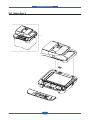
3.2.10 Transfer roller
1. Push HOLDER-TRANSFER, which holds the transfer roller and remove the roller from set.
Caution - Be carefull not to touch the sponge of Transfer Roller.
Service Manual
3-12
Samsung Electronics
Disassembly and Reassembly
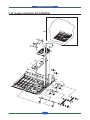
3.2.11 Holder Pad unit
1. Remove the CASSETTE from SET.
Service Manual
2. Disassemble HOLER-PAD after putting out three
HOOKs
3-13
Samsung Electronics
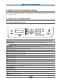
Alignment & Troubleshooting
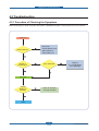
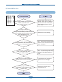
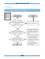
4. Alignment & Troubleshooting
This chapter describes the main functions for service, such as the product maintenance method, the test
output related to maintenance and repair, DCU using method, Jam removing method, and so on. It includes
the contents of manual.
4.1 Alignment and Adjustments
4.1.1 Control Panel overview
1
ID Copy
You can copy both sides of the ID Card like a driver’s license to a single side of paper.
2
Direct USB
Allows you to directly print files stored on a USB Memory device when it is inserted into the
USB memory port on the front of your machine. (SCX-4x28 Series only)
Reduce/Enlarge
Makes a copy smaller or larger than the original. (SCX-4x24 Series only)
3
Display
Shows the current status and prompts during an operation.
4
Status
Shows the status of your machine.
5
Fax
Activates Fax mode.
6
Copy
Activates Copy mode.
7
Scan/Email
Activates Scan mode.
8
Menu
Enters Menu mode and scrolls through the available menus.
9
Left/right arrow
Scroll through the options available in the selected menu, and increase or decrease values.
10
OK
Confirms the selection on the screen.
11
Back
Sends you back to the upper menu level.
12
Number keypad
Dials a number or enters alphanumeric characters.
13
Address Book
Allows you to store frequently used fax numbers in memory or search for stored fax numbers
or email addresses.
14
Redial/Pause
In ready mode, redials the last number, or in Edit mode, inserts a pause into a fax number.
15
On Hook Dial
Engages the telephone line.
16
Stop/Clear
Stops an operation at any time. In ready mode, clears/cancels the copy options, such as the
darkness, the document type setting, the copy size, and the number of copies.
17
Start
Starts a job.
Service Manual
4-1
Samsung Electronics
Alignment & Troubleshooting
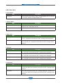
4.1.2 Understanding The Status LED
The color of the Status LED indicates the machine’s current status.
Status
Description
Off
7KHPDFKLQHLVSRZHUHGRIIOLQH
7KHPDFKLQHLVLQSRZHUVDYHPRGH:KHQGDWDLVUHFHLYHGRUDQ\
button is pressed, it switches to on-line automatically.
Green
Red
Service Manual
On
7KHPDFKLQHLVSRZHUHGRQDQGFDQEHXVHG
Blinking
:KHQWKHJUHHQ/('VORZO\EOLQNVWKHPDFKLQHLVUHFHLYLQJGDWDIURP
the computer.
:KHQWKHJUHHQ/('UDSLGO\EOLQNVWKHPDFKLQHLVSULQWLQJGDWD
On
$SUREOHPKDVRFFXUUHGVXFKDVDSDSHUMDPFRYHURSHQRUQRSDSHULQ
the tray, so that the machine cannot continue the job.
7KHWRQHUFDUWULGJHLVHPSW\RUQHHGVWREHFKDQJHG
Blinking
$PLQRUHUURUKDVRFFXUUHGDQGWKHPDFKLQHLVZDLWLQJIRUWKHHUURUWREH
cleared.
7KHWRQHUFDUWULGJHLVORZ2UGHUDQHZWRQHUFDUWULGJH
4-2
Samsung Electronics
Alignment & Troubleshooting
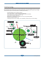
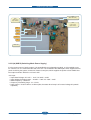
4.1.3 Paper path
Scanner Part
PICK-UP52//(5
$')52//(5
COVER OPEN
ADF-UPPER
)(('52//(5
EXIT 52//(5
$')/2:(5
SCAN UPPER
$')*/$66
:+,7(%$5
Engine Part
LSU
DEVE
FUSER
DUPLEX
CASSETTE
Service Manual
4-3
Samsung Electronics
Alignment & Troubleshooting
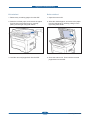
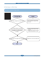
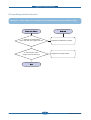
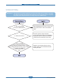
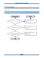
4.1.3.1 Clearing Document Jams
:KHQDQRULJLQDOMDPVZKLOHSDVVLQJWKURXJKWKH$')'RFXPHQW-DPDSSHDUVRQWKHGLVSOD\
Input Misfeed
4. Align the left end of the ADF roller with the slot
and push the right end of the ADF roller into the
right slot (1). Rotate the bushing on the right end
of the roller toward the document input tray (2).
1. Remove any remaining pages from the ADF.
2. Open the ADF cover.
1 ADF cover
5. Close the ADF cover. Then load the removed
page(s), if any, back into the ADF.
3. Rotate the bushing on the right end of the ADF
roller toward the ADF (1) and remove the roller
from the slot (2). Pull the document gently to the
left and out of the ADF.
Service Manual
4-4
Samsung Electronics
Alignment & Troubleshooting
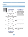
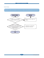
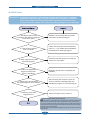
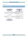
Exit misfeed
Roller misfeed
1. Remove any remaining pages from the ADF.
1. Open the scanner lid.
2. Seize the misfeed paper, and remove the paper
from the document output tray by carefully
pulling it to the right using both hands.
2. Seize the misfeed paper, and remove the paper
from the feed area by carefully pulling it to the
right using both hands.
/RDGWKHUHPRYHGSDJHVEDFNLQWRWKH$')
3. Close the scanner lid. Then load the removed
pages back into the ADF.
Service Manual
4-5
Samsung Electronics
Alignment & Troubleshooting
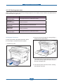
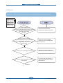
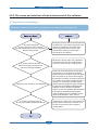
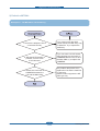
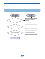
4.1.3.2 Clearing paper jams
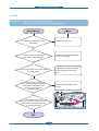
:KHQDSDSHUMDPRFFXUVWKHZDUQLQJPHVVDJHDSSHDUVRQWKHGLVSOD\VFUHHQ5HIHUWRWKHWDEOHEHORZWR
locate and clear the paper jam.
Message
Location of jam
Paper Jam 0
Open/Close Door
In the paper feed area or inside the machine
Paper Jam 1
Open/Close Door
Inside the machine
Paper Jam 2
Check Inside
Inside the machine or in the fuser area
Duplex Jam 0
Check Inside
Inside the machine
Duplex Jam 1
Open/Close Door
In the paper feed area or inside the machine
In the paper feed area
2. Remove the jammed paper by gently pulling it
straight out as shown below.
If paper is jammed in the paper feed area, follow
the next steps to release the jammed paper.
1. Pull the tray open.
If the paper does not move when you pull, or if
you do not see the paper in this area, check In
the toner cartridge area.
3. Insert the tray back into the machine. Printing
automatically resumes.
Service Manual
4-6
Samsung Electronics
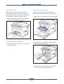
Alignment & Troubleshooting
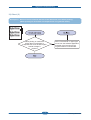
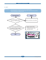
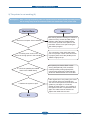
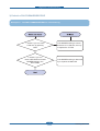
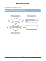
In the manual tray
In the toner cartridge area
:KHQ\RXSULQWXVLQJWKHPDQXDOWUD\DQGWKH
machine detects that there is either no paper or
that the paper has been improperly loaded, follow
the next steps to release the jammed paper.
If paper is jammed in the toner cartridge area,
follow the next steps to release the jammed paper.
1. Open the front cover and pull the toner cartridge
out
1. Check if the paper is stuck in the feeding area,
and if so, pull it out gently and slowly.
/RDGDSDSHULQWRWKHPDQXDOWUD\
2. Remove the jammed paper by gently pulling it
straight out as shown below.
3. Open the front cover and close it. The machine
will resume printing.
3. Replace the toner cartridge and close the front
cover. Printing automatically resumes.
Service Manual
4-7
Samsung Electronics
Alignment & Troubleshooting
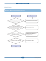
In the paper exit area
In the duplex unit area
If paper is jammed in the paper exit area, follow the
next steps to release the jammed paper.
If the duplex unit is not inserted correctly, paper
jam may occur. Make sure that the duplex unit is
inserted correctly.
1. If a long portion of the paper is visible, pull it
straight out. Open and close the front cover
¿UPO\7KHPDFKLQHZLOOUHVXPHSULQWLQJ
1. Pull the duplex unit out of the machine.
,I\RXFDQQRW¿QGWKHMDPPHGSDSHURULIWKHUHLV
any resistance removing the paper, stop pulling
and go to step 2.
2. Remove the jammed paper from the duplex unit.
2. Open the rear cover.
3. Pull the guide rear on each side down and
carefully take the jammed paper out of the
machine. Return the guide rear to its original
position.
If the paper does not come out with the duplex
unit, remove the paper from the bottom of the
machine.
1 Guide rear
4. Close the rear cover. Printing automatically
resumes.
Service Manual
,I\RXFDQQRW¿QGWKHMDPPHGSDSHURULIWKHUHLV
any resistance removing the paper, stop pulling
and go to step 3.
4-8
Samsung Electronics
Alignment & Troubleshooting
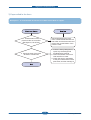
2. If you see the jammed paper, remove the paper
from the machine by gently pulling it straight out
as shown below.
3. Open the rear cover.
4. Pull the guide rear on each side down and
remove the paper. Return the guide rear to its
original position.
,I\RXFDQQRW¿QGWKHMDPPHGSDSHURULIWKHUHLV
any resistance removing the paper, stop pulling
and go to step 3.
3. Pull the tray half.
1 Guide rear
5. Close the rear cover. Printing automatically
resumes.
In the optional tray
If paper is jammed in the optional Tray, follow the
next steps to release the jammed paper.
1. Pull the optional tray open.
4. Remove the jammed paper by gently pulling the
paper straight up and out.
5. Insert the trays back into the machine. Printing
automatically resumes.
Service Manual
4-9
Samsung Electronics
Service Manual
Darkness
Resolution
Multi Send
Delay Send
Prio rity Se nd
Forw ard
Secur e Receive
Add Page
Cancel Job
Fax Feature
Sending
Redial Tim es
Redial Term
Prefix Dial
ECM Mode
Send Report
Image TCR
Dial Mode
Receiv ing
Receiv e Mode
Rin g to An swer
Fax Setup
Fax Setup
(Continued)
Stamp Rcv Name
Rcv Start Code
Auto Re duction
Discard Size
Ju nk Fax Set up
DRPD Mode
Dupl ex Pri nt
Change D efaul t
Resoluti on
Dark ness
Auto Re port
.
TCP/IP
Ethern et Spe ed
Clear Settin g
Network I nfo
Network
Reduce/Enlar ge
Darkness
Origina l Type
/D\ out
Norm al
2-Up
4-Up
ID Copy
Pos ter Cop y
Clon e Cop y
Adjus t Bk gd.
Copy Feature
Clear Settin g
All S etting s
Fax Setup
Copy Setu p
Scan Setup
Sys tem Setup
Network
Addre ss B ook
Sent Report
Fax Rcv Repo rt
System Setup
(Continued)
Duple x
Change Default
Copie s
Copy Colla tion
Redu ce/Enlar ge
Darkness
Origina l Type
Copy Setup
Report
All Report
Configura tion
Supplie s Info
Address Book
Send Report
Sent Report
Fax Rcv Repor t
Schedule Jobs
Junk Fax Report
Netw ork Info.
User Auth /LV t
Main tenance
&/R Empty Msg
Ignore Tone r
Supplie V/ ife
Serial N umbe r
System Setup
(Continued)
USB Feature
Scan Size
Origina l Type
Resolutio n
Scan Colo r
Scan Form at
E-mail Fe ature
Scan Size
Origina l Type
Resolutio n
Scan Colo r
Scan Form at
Scan Feature
Mach ine Setup
Mach ine ID
Mach ine Fax No.
Date & Time
Clock Mod e
/Dngu age
Default Mode
Power Sav e
Timeout
Job Timeout
Alt itude Adj.
Import Setting
Export Se tting
Paper Setup
Paper Si ze
Paper Type
Paper So urce
Sound/Vo lum e
Key Sou nd
Ala rm Sound
Speaker
Ringer
System Setup
Change Default
USB Default
E-mail Defa ult
Scan Setup
Alignment & Troubleshooting
4.1.4 Menu Map
The control panel provides access to various menus to set up the machine or use the machine’s functions.
These menus can be accessed by pressing Menu. Refer to the following diagram. Menus available in Fax,
Copy, or Scan mode vary.
4-10
Samsung Electronics
Alignment & Troubleshooting
4.1.4.1 Accessing to menus
The next steps are the example to print the menu map of this machine, and they are the general way to
VHOHFWPHQXDQGFRQ¿JXUH\RXUPDFKLQH
1. Make sure your machine is properly connected all the necessary cables, and turn on the machine.
2. Press the Menu button until you see the menu (ex. Information) you want on the bottom line of the display.
3. Press the OK button to access the menu.
3UHVVWKH/HIWULJKWDUURZEXWWRQVXQWLOWKHPHQXLWHPH[0HQX0DS\RXZDQWGLVSOD\VRQWKHERWWRP
line.
3UHVVWKH2.EXWWRQWRFRQ¿UPWKHVHOHFWHGLWHP
3UHVVWKH/HIWULJKWDUURZEXWWRQVXQWLOWKHPHQXLWHPH[3ULQW"\RXZDQWGLVSOD\VRQWKHERWWRPOLQH
7. Press the OK button to process your selection, save your input or selection.
An asterisk (*) appears next to the selection on the display, indicating that it is now the default.
8. To exit the menu, press the Back button repeatedly, or the Stop button.
Note - If you want to set the basic menu items, please consult the user guide.
Service Manual
4-11
Samsung Electronics
Alignment & Troubleshooting
4.1.5 Tech Mode
4.1.5.1 How to Enter Tech Mode
In service (tech) mode, the technician can check the machine and perform various test to isolate the cause
of a malfunction.
:KLOHLQ7HFKPRGHWKHPDFKLQHVWLOOSHUIRUPVDOOQRUPDORSHUDWLRQV
To enter the Tech mode
To enter the Tech mode, press
LQVHTXHQFHDQGWKH/&'EULHÀ\
GLVSOD\Vµ7(&+¶WKHPDFKLQHKDVHQWHUHGVHUYLFHWHFKPRGH
4.1.5.2 Setting-up System in Tech Mode
In service (tech) mode, the technician can check the machine and perform various test to isolate the cause
of a malfunction.
SCX-4824FN/4828FN
6HQG/HYHO
'70)/HYHO
Pause Time
Dial Mode
Modem Speed
Error Rate
RDS
Clear All Mem
Clear Counts
Flash Upgrade
Silence Time
Service Manual
Switch Test
Modem Test
Dram Test
Rom Test
Pattern Test
Shading Test
4-12
All Report
Protocol
Configuration
.H\+LVWRU\
Error Info
Usage Page
Component Check
Service Support
Samsung Electronics
Alignment & Troubleshooting
4.1.5.3 Data Setup
SEND LEVEL
You can set the level of the transmission signal. Typically, the Tx level should be under -12 dBm.
&DXWLRQ7KH6HQG)D[/HYHOLVVHWDWWKHEHVWFRQGLWLRQLQWKHVKLSPHQWIURPIDFWRU\1HYHUFKDQJHVHWWLQJV
arbitrarily.
DIAL MODE
This function can choose dial method.
*Default : Dial(Dial/Pulse)
MODEM SPEED
You can set the maximum modem speed.
Communication is done with modem speed automatically set at lower speed when communicating with a
slower speed modem since communication is done on the standard of the side where modem speed is low
for transmission/reception. It is best set 33.6Kbps as default setting.
ERROR RATE
:KHQWKHHUURUUDWHLVDERXWH[FHHGWKHVHWYDOXHWKH%DXGUDWHDXWRPDWLFDOO\DGMXVWVWRESV
This ensures that the error rate remains below the set value.
You can select the rate between 5% and 10%.
CLEAR ALL MEMORY
The function resets the system to factory default settings.
This function is used to reset the system to the initial value when the product is functioning abnormally. All the
values are returned to the default values, and all the information, which was set by the user, will be erased.
< Method >
6HOHFWWKH>0(025<&/($5@DWWKH7(&+02'(
2. Push the OK button.
3. Select you country. (There are four country groups. Refer to the table below.)
4. Push the OK button then it will clear all memory.
NOTICE : Always perform a memory clear after replacing the main board. Otherwise, the system may not
operate properly.
Country Group
USA/Canada
USA/Canada
Mexico
Brazil
Country
Service Manual
UK
UK
Germany
France
Italy
Spain
Austria
Netherlands
Belgium
Portugal
Sweden
Norway
Denmark
Finland
Switzerland
Greece
Ireland
Turkey
4-13
Russia
Russia
India
Oman
Poland
Bangladesh
Kuwait
Moroco
Algeria
Pakistan
UAE
Bahrain
Srilanka
Saudi Arabia
Chile
Peru
Argentina
+XQJDU\
Romania
Bulgaria
Czech
Southafrica
South Africa
Samsung Electronics
Alignment & Troubleshooting
Flash Upgrade
7KH)LUPZDUH8SJUDGHIXQFWLRQDQGKDVWZRPHWKRGV/RFDODQG5HPRWH
1) Local Machine Upgrade
5&35HPRWH&RQWURO3DQHOPRGH
This method is for USB Port Connect to PC and activate RCP(Remote Control Panel) to upgrade the
Firmware.
< Method >
+RZWR8SGDWH)LUPZDUHXVLQJ5&3
1. Connect PC and Printer with USB Cable.
2. Execute RCP and select Firmware Update.
6HDUFK)LUPZDUH¿OHWRXSGDWHZLWK%URZVH,FRQ
&OLFN8SGDWHLFRQ¿UPZDUH¿OHLVWUDQVPLWWHGWR3ULQWHUDXWRPDWLFDOO\DQGSULQWHULVLQLWLDOL]HGZKHQLW
¿QLVKHG
5. Click Refresh icon and check what is updated.
'26&RPPDQGPRGH
This method is just for USB Port. Connect to PC with USB cable and enter DOS Command to upgrade
the Firmware
< Method >
7KH¿UVWRIDOOQHHGWKH¿OHVGRZQEDWGRZQBFRPELQISUWH[HDQG5RP)LOH¿OHQDPHIRUXSJUDGH
6DYHWKH¿OHVLQWKHVDPHIROGHU
2. In the DOS, input as below and push the enter key. Then, it will be automatically upgraded.
3. There are two commands for the conditions of product.
:KHQWKHSURGXFWLVLQLGOHFRQGLWLRQGRZQ³URP¿OH´
:KHQWKHSURGXFWLVLQ5HDG\FRQGLWLRQ7(&+02'('$7$6(783)/$6+83*5$'(/2&$/FRS\E
³URP¿OH´OSW
4. Do not turn off the power while upgrading process.
2) Remote Upgrade
7KLVLVDIXQFWLRQWKDWDID[ZLWKWKHODWHVW¿UPZDUHVHQGV¿OHVWRDID[LQORQJGLVWDQFHWKURXJKWHOHSKRQH
line.
< Method >
%HIRUHUHPRWHXSJUDGHWKHODWHVW¿UPZDUHVKRXOGEHORDGHGLQWRWKHPDFKLQH
7(&+02'('$7$6(783)/$6+83*5$'(5(027(
2. Input the fax number, which needs to be upgraded. (Several faxes can be upgraded at the same time. In
this case, enter the each fax number.)
$IWHUSXVKWKHHQWHUEXWWRQVHQGWKH¿UPZDUH¿OHE\FDOOLQJWRWKHDSSRLQWHGQXPEHU$URXQGa
PLQXWHVQHHGVWRVHQGWKH¿OH
< Caution >
1. sending and receiving fax must be the same model.
2. A sending fax must be set up as ECM mode, and a receiving memory must be set up as 100%. If not, the
function operates abnormally
Service Manual
4-14
Samsung Electronics
Alignment & Troubleshooting
S/W of Maintenance
1. Clearing the Memory
<RXFDQVHOHFWLYHO\FOHDULQIRUPDWLRQVWRUHGLQ\RXUPDFKLQHVPHPRU\
1) Press Menu on the control panel until Maintenance appears on the top line of the display.
2) Press the scroll button (left-key or right-key) until you see Clear Memory on the bottom line and press
OK
7KH¿UVWDYDLODEOHPHQXLWHP&OHDU$OO0HPGLVSOD\VRQWKHERWWRPOLQH
6HHQH[WSDJH7KHUHDUHVRPHLWHPWRGLVSOD\RQWKH/&'
3) Press the scroll button (left-key or right-key) until you see the item you want to clear.
4) Press Enter. The selected memory is cleared and the display asks you to continue clearing the next
item.
5) To clear another item, press Enter and repeat steps 3 and 4
- To return to Standby mode, press Stop/Clear.
- As below item you can selectively clear information stored in your machine s memory.
&OHDU$OO0HP
- Clears all of the data stored in the memory and resets all of your settings to the factory default.
3DSHU6HWWLQJ
- Restores all of the Paper Setting options to the factory default.
&RS\6HWXS
- Restores all of the Copy Setup options to the factory default.
)D[6HWXS
- Restores all of the Fax Setup options to the factory default.
)D[)HDWXUH
- Cancels all of the scheduled fax jobs in the machine s memory.
- As below item you can selectively clear information stored in your machine s memory.
$GYDQFHG)D[
- Restores all of the Advanced Fax setting options to the factory default.
6RXQG9ROXPH
- Resets the sound and volume settings to the factory default.
0DFKLQH6HWXS
- Resets all of the system settings, such as the machine ID, date and time, display language and save
modes, to the factory default.
6HQW5HSRUW
- Clears all of records of your faxes sent.
5&95HSRUW
- Clears all of records of your faxes received.
3KRQH%RRN
- Clears the one-touch, speed and group dial numbers stored in the memory.
2. Adjust shading
:KHQWKHVFDQXQLWEHFRPHVGLUW\LWFDQDOWHUWKHVKDGLQJYDOXH
,I\RXUFRS\KDVEODFNOLQHVRULVEOXUUHGDGMXVWWKHVKDGLQJVHWWLQJ
/RDGDVKHHWRIZKLWHSDSHULQWRWKH$')
2) Make machine Tech mode.
3) Press Menu on the control panel and scroll until Machine Test displays.
4) Scroll to Shading Test and Press OK.
5) Select Shading&Print appears on the bottom line and press OK.
6) Your machine picks up the paper and adjusts the shading value.
7) After adjusting, shading value will be printed with graphic image.
Service Manual
4-15
Samsung Electronics
Alignment & Troubleshooting
3. Remote Diagnostic System(RDS)
5'6DQG)7(*7$XWRPDWLF2UGHULQJ6\VWHPZLOOHQKDQFHWKHTXDOLW\DQGWKHVSHHGRIDIWHUVDOHV
service and monitor the performance of the MFP at the customer site.
0)36KRXOGEHFRQQHFWHGE\0)36HUYHU
3.1 Required components of RDS
RDS for MFP system consists of the following three components that communicate with each other
1. Main RDS Server connected to FAX-MODEM.
2. RDS Client Application.
3. RDS on MFP.
3.2 Enable of RDS on MFP
This value is in Tech Mode.
The factory default for Consumables Status Update / Error Proactive value is Disabled.
< Method >
1. MFP Should be connected by RDS Server.
2. Service numbers should have the proper values.
7(&+02'(!'$7$6(783!127,)<721(5!5'6!6HUYLFH1XPEHU
3. Machine Serial No. should have the proper values.
7(&+02'(!'$7$6(783!127,)<721(5!7RQHU!6HULDO1R
4. Criter value input is optional, default is set to 1000-page.
7(&+02'(!'$7$6(783!127,)<721(5!5'6!&ULWHU9DOXH
5. Remote Test should be On
0DLQWHQDQFH!5HPRWH!7HVW2Q
6. Change the password : if you forgot the Notify Toner password, enter the new password.
7(&+02'(!'$7$6(783!127,)<721(5!5'6!5'63DVVZRUG
,I\RXDUHWRHQDEOHWKH5'6V\VWHP1RWLI\7RQHURSWLRQVKRXOGEH>2II@
3.3 Call setup & Release
In order to perform any RDS activity on a Customer MFP, the SVC will have to setup a call to it.
2QVXFFHVVIXOFRPSOHWLRQRIFDOOVHWXSRQHRUPRUH5'6IXQFWLRQVFDQEHH[HFXWHGEHIRUHFDOOUHOHDVHLV
manually initiated.
:KHQFRQQHFWLQJWRDGHYLFH5'6ZLOOTXHU\WKH0)3IRUVHULDOQR,I6HULDO1RLVD]HUROHQJWKVWULQJ
invalid string, user will be prompted to enter a valid serial no. for the device. If the user chooses not to enter
WKHVHULDOQXPEHUDWWKDWSRLQWKHFDQHQWHUHGLWLWODWHUDOVR6HULDOQXPEHUZLOOEHFRQ¿JXUDEOHMXVWOLNHDQ\
other MFP parameter
)ROORZLQJVXFFHVVIXOFRQQHFWLRQIROORZLQJGHWDLOVRIWKH0)3ZLOOEHGLVSOD\HG
Tel. No, Model, Server Port (that is connected to), Status, Serial Number, Firmware Version, Engine
Version, Emulation Version
,QFDVHWKHHVWDEOLVKHGFDOOLVGURSSHGGXHWRDQHUURUFRQGLWLRQ5'6&OLHQW$SSOLFDWLRQZLOOQRWLI\WKHXVHU
It will then be necessary to manually request for another call setup to the desired MFP before any RDS
function can be reattempted.
,IQRDFWLYLW\LVGHWHFWHGRQDFRQQHFWHGFDOOIRUDPD[LPXPGXUDWLRQRIPLQXWHVVHFRQGVWKHFDOO
will be released / disconnected from the MFP-side.
Service Manual
4-16
Samsung Electronics
Alignment & Troubleshooting
4.1.5.4 Machine Test
SWITCH TEST
8VHWKLVIHDWXUHWRWHVWDOONH\VRQWKHRSHUDWLRQFRQWUROSDQHO7KHUHVXOWLVGLVSOD\HGRQWKH/&'ZLQGRZ
each time you press a key.
MODEM TEST
Use this feature to hear various transmission signals to the telephone line from the modem and to check the
modem. If no transmission signal sound is heard, it means the modem part of the main board malfunctioned.
DRAM TEST
8VHWKLVIHDWXUHWRWHVWWKHPDFKLQH¶V'5$07KHUHVXOWDSSHDUVLQWKH/&'GLVSOD\
,IDOOPHPRU\LVZRUNLQJQRUPDOO\WKH/&'VKRZV2.!!
ROM TEST
8VHWKLVIHDWXUHWRWHVWWKHPDFKLQH¶65207KHUHVXOWDQGWKHVRIWZDUHYHUVLRQDSSHDULQWKH/&'GLVSOD\
)/$6+9(59
(1*,1(9(59
PATTERN TEST
Using this pattern printout, you can check if the printer mechanism is functioning properly.
It is needed in the production progress. Service person doesn’t need to use it.
SHADING TEST
7KHIXQFWLRQLVWRJHWWKHRSWLPXPVFDQTXDOLW\E\WKHVSHFL¿FFKDUDFWHURIWKH&&'&KDUJH&RXSOHG
Device). If the copy image quality is poor, perform this function to check the condition CCD unit.
< Method >
6HOHFWWKH>$'-8676+$',1*@DWWKH7(&+02'(
2. Push the SET UP button then an image will be
scanned.
$IWHUWKHVFDQ&&'6+$',1*352),/(ZLOOEH
print out.
4. If the printed image is different to the image, the
CCD is defect.
NOTICE : When you test CCD, make sure that the
cover is closed.
Service Manual
4-17
Samsung Electronics
Alignment & Troubleshooting
4.1.5.5 Report
PROTOCOL LIST
This list shows the sequence of the CCITT group 3 T.30 protocol during the most recent sending or receiving
operation. Use this list to check for send and receive errors. If a communication error occurs while the
PDFKLQHLVLQ7(&+PRGHWKHSURWRFROOLVWZLOOSULQWDXWRPDWLFDOO\
OTHER ITEM
This list provides a list of the user system data settings and tech mode settings.
&RQ¿JXUDWLRQUHSRUW
Service Manual
4-18
Samsung Electronics
Alignment & Troubleshooting
supplies information report
Service Manual
4-19
Samsung Electronics
Alignment & Troubleshooting
4.1.6 EDC Mode
EDC Mode is independently controled system f/w and diagnose printer’s each function.
Ŷ0HWKRGWRHQWHU
$IWHUWXUQRQWKHV\VWHPSRZHUFKHFNWKH³5HDG\´PHVVDJHRQWKH/&'
2. To enter the EDC Mode, Push the button like next time.
³0HQXĺ6WRSĺ/HIWDUURZĺ%DFNĺ2.ĺ5LJKWDUURZ´
7KHPHVVDJH³&20321(177(673UHVV0HQX.H\´GLVSOD\RQWKH/&'
7RJHWRXWRIWKH('&0RGH3UHVVWKH³6WRS´NH\
Service Manual
4-20
Samsung Electronics
Alignment & Troubleshooting
Ŷ('&0RGH0HQX
0. Cover Status
Item
Front Cover
Description
:KHQWKHIURQWFRYHURSHQHG³2SHQ´PHVVDJHGLVSOD\/&',IWKHIURQW
FRYHUFORVHG³&ORVHG´PHVVDJHGLVSOD\/&'
1. Sensor Status
Item
Description
Regi/Feed/Exit Sensor
,IDFWXDWRULVFKHFNHGE\VHQVRU:LWKRXW3DSHUPHVVDJHZLOOEH
GLVSOD\HGLIQRW:LWK3DSHUZLOOEH
Empty
,ISDSHUH[LVWVLQWKHWUD\³3UHVHQWZLOOEHGLVSOD\HG,IQRW³(PSW\ZLOO
be.
2. Motor Test
Item
Description
Main Mtr Nor.
,I³2.´NH\LVSXVKHGDIWHU³21´GLVSOD\HGPRWRUZLOOEHUXQ0DLQPRWRU
ZLOODXWRVWRSDIWHUVHFRQGVDQG´2))´PHVVDJHZLOOEHGLVSOD\HG
Slow
,I³2.´NH\LVSXVKHGDIWHU³21´GLVSOD\HGPRWRUZLOOEHVORZO\UXQ
0DLQPRWRUZLOODXWRVWRSDIWHUVHFRQGVDQG´2))´PHVVDJHZLOOEH
displayed.
3. Fan Test
Item
Description
Fuser Fan
,I³2.´NH\LVSXVKHGDIWHU³21´GLVSOD\HGIDQZLOOEHUXQ)XVHUIDQZLOO
DXWRVWRSDIWHUVHFRQGVDQG´2))´PHVVDJHZLOOEHGLVSOD\HG
SMPS Fan
,I³2.´NH\LVSXVKHGDIWHU³21´GLVSOD\HGIDQZLOOEHUXQ6036IDQZLOO
DXWRVWRSDIWHUVHFRQGVDQG´2))´PHVVDJHZLOOEHGLVSOD\HG
/68)DQ
,I³2.´NH\LVSXVKHGDIWHU³21´GLVSOD\HGIDQZLOOEHUXQ/68IDQZLOO
DXWRVWRSDIWHUVHFRQGVDQG´2))´PHVVDJHZLOOEHGLVSOD\HG
4. Clutch Test
Item
Description
Pick up Clutch
:KHQ³2.´NH\LVSXVKHGDIWHU´21´PHVVDJHGLVSOD\HGFOXWFKWXUQRQ
SLFNXSFOXWFKZLOOEHWXUQRIIDIWHUVHFRQGVDQG´2))´PHVVDJHZLOOEH
displayed.
Regi Clutch
:KHQ³2.´NH\LVSXVKHGDIWHU´21´PHVVDJHGLVSOD\HGFOXWFKWXUQRQ
SLFNXSFOXWFKZLOOEHWXUQRIIDIWHUVHFRQGVDQG´2))´PHVVDJHZLOOEH
displayed.
Service Manual
4-21
Samsung Electronics
Alignment & Troubleshooting
5. Fuser Ctrl
Item
Description
Temp Control
)XVHURQDQGRII³21´LVVHOHFWHGIXVHUZLOOEHDFWLYHDQGGLVSOD\WKH
IXVHUWHPSHUDWXUH>;;;@EXW³2))´LVVHOHFWHGIXVHUZLOOEHVWRSDQG>@
display
Fuser Temp.
)XVHUWHPSHUDWXUHGLVSOD\HGRQ/&'H[DPSOH>@
6. LSU Control
Item
Description
/'3RZHU
:KHQ³2.´NH\LVSXVKHGDIWHU´21´PHVVDJHGLVSOD\HG´2))´PHVVDJH
will be displayed after 10 seconds
/680RWRU
,I³2.´NH\LVSXVKHGDIWHU³21´GLVSOD\HGPRWRUZLOOEHUXQ/68PRWRU
ZLOODXWRVWRSDIWHUVHFRQGVDQG´2))´PHVVDJHZLOOEHGLVSOD\HG
/685HDG\
,I³2.´NH\LVSXVKHGDIWHU³21´GLVSOD\HGPRWRUZLOOEHUXQ´´PHVVDJH
will be displayed.
+V\QF
,I³2.´NH\LVSXVKHGDIWHU³21´GLVSOD\HGPRWRUZLOOEHUXQ´´PHVVDJH
will be displayed.
7. DEV Control
Item
Description
7+9
,I³2.´NH\LVSXVKHGDIWHU³21´GLVSOD\HG7+9ZLOOEHWXUQHGRQ
7+9
,I³2.´NH\LVSXVKHGDIWHU³21´GLVSOD\HG7+9ZLOOEHWXUQHGRQ
Dev Bias
,I³2.´NH\LVSXVKHGDIWHU³21´GLVSOD\HG'HY%LDVZLOOEHWXUQHGRQ
0+9%LDV
,I³2.´NH\LVSXVKHGDIWHU³21´GLVSOD\HG0+9%LDVZLOOEHWXUQHGRQ
Ŷ$&521<06$1'$%%5(9,$7,216
'(9'HYHORSLQJ+LJK9ROWDJH
('&(PEHGGHG'LDJQRVWLF&RQWURO
):±)LUPZDUH
+936±+LJK9ROWDJH3RZHU6XSSO\
+:+DUGZDUH
/'±/DVHU'LRGH
/68±/DVHU6FDQQLQJ8QLW
0+90DLQ+LJK9ROWDJH&KDUJH9ROWDJH
23&2SWLFDO3KRWR&RQGXFWRU
6&)6HFRQG&DVVHWWH)HHGHU
7+97UDQVIHU+LJK9ROWDJH
Service Manual
4-22
Samsung Electronics
Alignment & Troubleshooting
4.1.7 Abnormal Image Printing and Defective Roller
If abnormal image prints periodically, check the parts shown below.
7-2
7-1
No
Roller
Abnormal image period
Kind of abnormal image
1
OPC Drum
75.5mm
:KLWHVSRW%ORFN6SRWV
2
Charge Roller
26.7mm
Block Spot and Periodic Band
3
Supply Roller
47.1mm
Periodic Band by little difference of density
4
Developing Roller
35.2mm
:KLWH6SRW+RUL]RQWDOEODFNEDQG
5
Transfer Roller
47mm
Ghost, Damaged Image by abnormal transfer
6
+HDW5ROOHU
77.8mm
Black Spots or Vertical Black Band
7-1
3UHVVXUH5ROOHUBVW
62.8mm
Blackground
7-2
3UHVVXUH5ROOHUBVW
37.7mm
Blackground
Service Manual
4-23
Samsung Electronics
Alignment & Troubleshooting
4.1.8 Error Message
Messages appear on the control panel display to indicate the machine’s status or errors. Refer to the tables
below to understand the messages’ meaning and correct the problem if necessary. Messages and their
meanings are listed in alphabetical order.
[[[LQGLFDWHVWKHPHGLDW\SH
\\\LQGLFDWHVWKHWUD\
Message
Meaning
Suggested solutions
[COMM. Error]
The machine has a communication
problem.
Ask the sender to try again.
[Incompatible]
The machine has received a fax from
which is registered as a junk fax.
The received fax data will be deleted.
5HFRQ¿UPMXQNID[VHWXS
[Line Error]
Your machine cannot connect with the
receiving fax machine or has lost
contact because of a problem with the
phone line.
Try again. If the problem persists, wait
an hour or so for the line to clear and
try again.
Or, turn the ECM mode on.
[No Answer]
The receiving fax machine has not
answered after several redial
attempts.
Try again. Make sure that the receiving
machine is operational.
[Stop Pressed]
Stop/Clear has been pressed during
an operation.
Try again.
[yyy]
Paper Empty
There is no paper in the tray.
/RDGSDSHULQWKHWUD\
[yyy]
Paper Mismatch
7KHSDSHUVL]HVSHFL¿HGLQWKHSULQWHU
properties does not match the paper
you are loading.
/RDGWKHFRUUHFWSDSHULQWKHWUD\
Authentication
Failure
The ID or password you entered is
incorrect.
Enter the correct ID or password.
Cancel?
Ĵ Yes Ķ
Your machine’s memory has become To cancel the fax job, press the OK
full while trying to store an original into button to accept Yes. If you want to
memory.
send those pages that have been
successfully stored, press the OK
button to accept No. You should send
the remaining pages later, when
memory is available.
Connection Error
Connection with the SMTP server
failed.
Check the server settings and the
network cable.
Data Read Fail
Check USB Mem.
Time expired while reading data.
Try again.
Data Write Fail
Check USB Mem.
Storing to the USB memory failed.
Check the available USB memory
space.
Service Manual
4-24
Samsung Electronics
Alignment & Troubleshooting
Message
Meaning
Suggested solutions
Document Jam
The loaded original has jammed in the Clear the jam.
ADF.
Door Open
The front cover is not securely
latched.
Close the cover until it
locks into place.
Duplex Jam 0
Check Inside
Paper has jammed during duplex
printing. This is applicable only to
machines with this feature.
Clear the jam.
Duplex Jam 1
Open/Close Door
Paper has jammed during duplex
printing. This is applicable only to
machines with this feature.
Clear the jam.
Enter Again
You entered an unavailable item.
Enter the correct item again.
File Format
Not Supported
7KHVHOHFWHG¿OHIRUPDWLVQRW
supported.
8VHWKHFRUUHFW¿OHIRUPDW
Fuser Fan
Locked
There is a problem in the cooling fan
of the machine.
Open and then close the front cover.
Group Not
Available
Use a speed dial number or dial a
You have tried to select a group
number manually using the number
location number where only a single
location number can be used, such as keypad.
when adding locations for a Multiple
Send operation.
Install Toner
The toner cartridge is not installed.
Install the toner cartridge.
Invalid Toner
The toner cartridge you have installed
is not for your machine.
Install the a Samsunggenuine toner
cartridge designed for your machine.
,3&RQÀLFW
The network IP address you have set
is being used by someone else.
Check the IP address and reset it if
necessary.
Line Busy
The receiving fax machine did not
Try again after a few minutes.
answer or the line is already engaged.
Low Power
The machine is in the previous stage
of the power save mode.
:KHQGDWDLVUHFHLYHGLWVZLWFKHVWR
on-line automatically.
Mail Exceeds
Server Support
The mail size is larger than the
supported size by SMTP server.
Divide your mail or reduce the
resolution.
Main Motor Locked
There is a problem in the main motor.
Open and then close the front cover.
Memory Full
The memory is full.
Delete unnecessary fax jobs and
retransmit after more memory
becomes available. Alternatively, split
the transmission into more than one
operation.
Not Assigned
The speed button or speed dial
number you tried to use has no
number assigned to it.
Enter the number manually using the
number keypad or store the number or
address.
Service Manual
4-25
Samsung Electronics
Alignment & Troubleshooting
Message
Meaning
Suggested solutions
Not Available
Try Again Later
Can not perform the task immediately
because too many tasks are running
at once.
Try again when current task is
completed.
One Page is
Too Large
Single page data exceeds the
FRQ¿JXUHGPDLOVL]H
Reduce the resolution and try again.
Operation Not
Assigned
You are in the Add Page/Cancel Job
operation, but there are no jobs
stored.
Check the display to see if there are
any scheduled jobs.
Out-Bin Full
The output tray of the machine is full
of paper.
Remove paper.
Paper Jam 0
Open/Close Door
Paper has jammed in the feeding area Clear the jam.
of the tray.
Paper Jam 1
Open/Close Door
Paper has jammed inside the
machine.
Paper Jam 2
Check Inside
Special print media has jammed in the Clear the jam.
paper exit area.
Replace Toner
This message appears between Toner Replace the toner cartridge with a new
(PSW\DQG7RQHU/RZVWDWXV
one.
Retry Redial?
7KHPDFKLQHLVZDLWLQJIRUDVSHFL¿HG You can press OK to immediately
redial, or Stop/Clear to cancel the
time interval to redial a previously
redial operation.
busy station.
Scanner locked
The scanner module is locked
Unlock the scanner and press Stop/
Clear.
Self Diagnostics
Temperature
The engine in your machine is
checking problems detected.
:DLWDIHZPLQXWHV
Self Diagnostics
LSU
7KH/68/DVHU6FDQQLQJ8QLWLQ
your machine is checking problems
detected.
:DLWDIHZPLQXWHV
Send Error
(AUTH)
There is a problem in SMTP
authentication.
&RQ¿JXUHWKHDXWKHQWLFDWLRQVHWWLQJ
Send Error
(DNS)
There is a problem in DNS.
&RQ¿JXUHWKH'16VHWWLQJ
Send Error
(POP3)
There is a problem in POP3.
&RQ¿JXUHWKH323VHWWLQJ
Send Error
(SMTP)
There is a problem in SMTP.
Change to the available server.
Send Error
:URQJ&RQ¿J
There is a problem on the network
interface card.
&RQ¿JXUH\RXUQHWZRUNLQWHUIDFHFDUG
correctly.
Service Manual
4-26
Clear the jam.
Samsung Electronics
Alignment & Troubleshooting
Message
Meaning
Suggested solutions
Toner Empty
The toner cartridge has run out. The
machine stops printing.
Press OK to toggle the message to
Stop or Continue.
Ĵ Stop Ķ
You can select the option among Stop
or Continue with the left/right arrow.
If you select Stop by pressing OK on
the control panel, the machine stops
printing. If you select Continue, the
machine keeps printing, but the quality
cannot be guaranteed.
If you do not select any, the machine
will work as Stop is selected.
Replace the toner cartridge with a new
one.
Toner Exhausted
The lifespan of the toner cartridge
which the arrow indicates is reached.
This message appears when the
toner is completely empty, and your
machine stops printing. Replace the
corresponding toner cartridge with a
Samsunggenuine cartridge.
Toner Low
The corresponding toner cartridge is
almost empty.
Take out the toner cartridge and
thoroughly shake it. By doing this, you
can temporarily reestablish printing
operations.
Updating Data
Please Wait...
This message appears when there is
a change in the system setting or
when you back up a data.
Do not turn the power off when this
message is showing. Changes may
not be saved and datas can be lost.
Service Manual
4-27
Samsung Electronics
Alignment & Troubleshooting
4.2 Troubleshooting
4.2.1 Procedure of Checking the Symptoms
%HIRUHDWWHPSWLQJWRUHSDLUWKHSULQWHU¿UVWREWDLQDGHWDLOHGGHVFULSWLRQRIWKHSUREOHPIURPWKHFXVWRPHU
Power On
*UHHQ/('RQ"
- No Power
- Power Module error
- Main PBA error
- Panel PBA error
Ready or
Power save
(UURU/('21"
Refer to
/('6WDWXV
Error Message
Test Print
printing
Quality is
1RPDO"
Refer to "Solution
of Image Problem"
END
Service Manual
4-28
Samsung Electronics
Alignment & Troubleshooting
4.2.2 The cause and solution of Bad image
1) Vertical Black Line and Band
Description : 1. Straight thin black vertical line occurs in the printing.
2. Dark black vertical band occur in the printing.
Digital Printer
Digital Printer
Digital Printer
Digital Printer
Digital Printer
1. Damaged develop roller in
the Toner cartridge. Deformed Doctor-blade
or cleaning-blade.
2. Scratched surface of
the charge roller in the toner cartridge.
3. Partly depression or
deformation on the surface of
the transfer roller.
Service Manual
4-29
If causes 1 and 2 occur in the
toner cartridge, replace the toner
cartridge and try to print out.
Replace the transfer roller if
occurred as No. 3.
Samsung Electronics
Alignment & Troubleshooting
2) Vertical White Line
Description : White vertical voids in the image.
Digital Printer
Digital Printer
Digital Printer
Digital Printer
Digital Printer
1. Foreign matter stuck onto the
window of internal lenses
RI/68PLUURU.
2. Foreign matter or
toner particles between the toner
cartridge roller and blade. (In case the life of the
toner cartridge has been expired, white
lines or light image occur in
front of the image.)
Replace the toner cartridge.
3. It may occur when Burr and
foreign substances are on the window
of the toner cartridge frame.
No 3. : Remove the foreign matter
and burr of the exposure window.
(toner cartridge)
4. If the fuser is defective,
voids occur periodically at the
top of a black image.
No. 4. : Open the front cover and
check ribs that corresponds to the
position of the voids. Remove if
found.
5. It may occur when foreign
substances are on the OPC Drum.
6. Partly depression or
deformation on the surface of the
transfer roller
Service Manual
Foreign matter stuck onto the
ZLQGRZ&OHDQWKH/68ZLQGRZ
with recommended cleaner(IPA)
Clean the window with a clean
cotton swab.
4-30
If the problems are not solved,
replace the toner cartridge.
Replace the transfer roller if
occured as NO.6
Samsung Electronics
Alignment & Troubleshooting
3) Horizontal Black Band
Description : Dark or blurry horizontal stripes occur in the printing periodically.
(They may not occur periodically.)
Digital Printer
Digital Printer
Digital Printer
Digital Printer
Digital Printer
Service Manual
1. Bad contacts of the voltage
terminals to toner cartridge.
Clean each voltage terminal of the
Charge, Supply, Develop and
Transfer roller. (remove the toner
particles and paper particles)
2. The rollers of toner
cartridge may be stained.
Charge roller = 26.7mm
Supply roller = 47.1mm
Develop roller = 35.2mm
Transfer roller = 47mm
1. Clean the right Gear that has
relatively small gap of the teeth
in the OPC.
2. If the malfunction persists,
replace the toner cartridge.
4-31
Samsung Electronics
Alignment & Troubleshooting
4) Black/White Spot
Description : 1. Dark or blurry spots occur periodically in the printing
2. White spots occur periodically in the printing
Digital Printer
Digital Printer
Digital Printer
Digital Printer
Digital Printer
1. If dark or blurry
black spots occur periodically,
the rollers in the Toner cartridge may
be
or
be contaminated
contaminated with
with foreign
foreign matter
matte or
paper particles.
26.7 mm interval
( Charge roller : 37.7
OPC drum : 75.5 mm interval)
2. If faded areas or
voids occur in a black image
at intervals of 75.5 mm, or black spots
occur elsewhere, the OPC drum
surface is damaged.
3. If a black image is
partially broken, the transfer
voltage is abnormal or the transfer
roller's life has expired.
Service Manual
4-32
Run OPC cleaning Mode Print
and run the Self-test 2 or 3 times.
In case of 75.5 mm interval
unremovable in 1, cleanly remove
foreign substances stuck on the
OPC location equivalent to black
spots and white spots with a dry
duster.
1. The transfer roller guarantees
50,000 sheets printing. If the
roller's life is expired, replace it.
2. In case of 75.5 mm interval
unremovable in 1, take measures
as to replace the toner cartridge
and try to print out.
3. Clean the inside of the set
against the paper particles and
foreign matter in order not to
cause the trouble.
Samsung Electronics
Alignment & Troubleshooting
5) Light Image
Description : The printed image is light, with no ghost.
Digital Printer
Digital Printer
Digital Printer
Digital Printer
Digital Printer
1. Develop roller is
stained when the toner of toner
cartridge is almost consumed.
No 1 : Replace the toner cartridge
and try to print out.
1R:ait 30 minutes after printer
is powered on before you start
printing.
2. Ambient temperature
is below than 10.
3. Bad contact
caused by the toner stains
between the high voltage terminal in
WKH+936DQGWKHRQH
in the set.
4. Abnormal output
IURPWKH+936
5XQVHOIWHVWDQGFKHFNa
Service Manual
Check if the Toner Save mode is off.
Check if the density is light.
4-33
No3 : Clean up the contaminated
area by the toner.
5HSODFHWKH+936LIWKH
problems are not solved by the
above four instructions.
Samsung Electronics
Alignment & Troubleshooting
6) Dark Image or a Black Page
Description : The printed image is dark.
Digital Printer
Digital Printer
Digital Printer
Digital Printer
Digital Printer
1. No charge voltage in the engine board.
Service Manual
Check the state of the connector
which connects the engine board
DQG+936
2. Charge voltage is not turned
on due to the bad contacts between
power supply in the side of the Toner
cartridge and charge terminal
RI+936
1. Clean the high voltage charge
terminal.
5HSODFHWKH+936LIQRWVROYHG
by the above direction 1 and 2.
3. VD0 signal of the Main PBALV/RZVWDWH
5HSODFHWKH/688QLWRU0DLQ3%$
4-34
Samsung Electronics
Alignment & Troubleshooting
7) Uneven Density
Description : Print Density is uneven between left and right.
1. The pressure force
on the left and right springs of the
transfer roller is not even, the springs are
damaged, the transfer roller is improperly
installed, or the transfer roller
bushing or holder is
damaged.
2. The life of the Toner cartridge
has expired.
3. The toner level is not even on
the toner cartridge roller due to the
bad blade.
Service Manual
4-35
Replace both the left and right
6SULQJ+ROGHU.
Occur in the toner cartridge gently
shake the toner cartridge.
Replace the toner cartridge and
try to print out.
Samsung Electronics
Alignment & Troubleshooting
8) Background
Description : Light dark background appears in whole area of the printing.
Digital Printer
Digital Printer
Digital Printer
Digital Printer
Digital Printer
1. Does character exist less than
2% per a page, and hasnÕt it been
XVHGORQJWLPH"
,VDUHF\FOHGWRQHUFDUWULGJHEHXVHG"
The A/S is not guaranteed if using
a recyled the toner cartridger.
+DVWKHOLIHVSDQRIWKHWRQHU
FDUWULGJHHQGHG"
Replace the toner cartridge when
the life span of it has been ended.
4. Is the movement(Up and Down)
RIWKHWUDQVIHUUROOHUVPRRWK"
Clean the bushing part of the
transfer roller.
1. If the problem is still not solved,
replace the toner cartridge.
2. Gently shake the toner
cartridge.
,VWKH+936QRUPDO"
Service Manual
The toner cartridge is basically
designed to print 7K sheets with
5% image. If it prints more than
8K sheets with 2% coverage, a
background can occur.
4-36
Samsung Electronics
Alignment & Troubleshooting
9) Ghost (1)
Description : Ghost occurs at 75.5 mm intervals of the OPC drum in the whole printing.
75.5mm
Digital Printer
Digital Printer
Digital Printer
Digital Printer
Digital Printer
Digital Printer
1. Bad contacts
caused by contamination
from toner particles between high voltage
terminal in the main body and the
electrode of the Toner
cartridge.
Clean the terminals when
contaminated by toner particles.
2. Bad contacts caused
by contamination from toner particles
between high voltage terminal in the main
body and the one in the
+936ERDUG
Occur in the toner cartridge,
replace the toner cartridge and
try to print out.
3. The life of toner cartridge is expired.
4. Transfer roller lifetime(50K sheets)
has expired.
Replace the engine board if not
solved by the above directions 1-2.
If not solved by the direction 3,
check the transfer roller lifetime
and replace it.
Continue..
Service Manual
4-37
Samsung Electronics
Alignment & Troubleshooting
Continue..
:ait about 1 hour after power on
before using printer.
5. Abnormal low temperature
(below 10).
Occur in the toner cartridge,
replace the toner cartridge and
try to print out.
6. Damaged cleaning blade in the
toner cartridge.
Service Manual
4-38
Samsung Electronics
Alignment & Troubleshooting
10) Ghost (2)
Description : Ghost occurs at 75.5 mm intervals of the OPC drum in the whole printing.
(When printing on card stock or transparencies using manual feeder)
75.5mm
Digital Printer
Digital Printer
Digital Printer
Digital Printer
Digital Printer
Digital Printer
:KHQSULQWLQJRQFDUGVWRFN
thicker than normal paper or
WUDQVSDUHQFLHVVXFKDV2+3, higher
transfer voltage is
required.
Service Manual
4-39
Select 'Thick Mode' on paper type
menu from the software application
and after using returning to the
original mode is recommended.
Samsung Electronics
Alignment & Troubleshooting
11) Ghost (3) : Fuser
Description : Ghost occurs at 62.8 mm or 77.6mm intervals.
62.8 or 77.6mm
Digital Printer
Digital Printer
Digital Printer
Digital Printer
Digital Printer
Digital Printer
The temperature of the fuser is
maintained high.
Service Manual
4-40
Disassemble the fuser and remove
the contaminated toner particles on
the roller and clean the foreign
matter between Thermistor and
+HDWUROOHU.
(Caution: can be deformed)
Samsung Electronics
Alignment & Troubleshooting
12) Stains on the Face of Page
Description : The background on the face of the printed page is stained.
Digital Printer
Digital Printer
Digital Printer
Digital Printer
Digital Printer
Service Manual
1. Toner leakage due to improperly
sealed toner cartridge.
Replace the toner cartridge.
2. If the transfer roller is
contaminated, stains on the face of
page will occur.
If the transfer roller is
contaminated, run PC Cleaning
Mode Print 2 or 3 times.
And perform Self-Test 2 or 3 times
to remove contamination.
4-41
Samsung Electronics
Alignment & Troubleshooting
13) Stains on Back of Page
Description : The back of the page is stained at 47 mm or 62.8mm intervals.
47 or 62.8mm
Digital Printer
Digital Printer
Digital Printer
Digital Printer
Digital Printer
Digital Printer
Perform the OPC Cleaning Mode
Print 2 or 3 times. Run Self-Test to
remove the contamination of the
transfer roller.
1. 47mm : Transfer roller is
contaminated.
2. 62.8mm : Pressure roller is
contaminated.
Service Manual
4-42
1. Replace the transfer roller if
contaminated severely.
2. Disassemble the fuser and clean
WKH+5+HDW5ROOHUDQG35
(Pressure roller). And check the
DUHDEHWZHHQ+5DQGThermistor.
If contaminated, clean the area
not to be deformed.
Samsung Electronics
Alignment & Troubleshooting
14) Blank Page Print out (1)
Description : Blank page is printed.
Digital Printer
Digital Printer
Digital Printer
Digital Printer
Digital Printer
Bad ground contacts in OPC and/or
toner cartridge.
Service Manual
4-43
1. Check if the Ground-OPC is
defective(set inside right side).
2. Remove contamination of the
terminals of the toner cartridge
and the unit.
Samsung Electronics
Alignment & Troubleshooting
15) Blank Page Print out (2)
Description : 1. Blank page is printed.
2. One or several blank pages are printed.
3. When the printer turns on, several blank pages print.
1. Bad ground contacts in OPC and/or
toner cartridge.
1. Perform the engine self test
using EDC Mode to check if the
Solenoid is normal.
2. If not solved by the above
directions 1-2, Replace the
engine board.
3. Turn the power off, delete the
data of PC and try printing again.
2. Abnormal solenoid.
Service Manual
Remove contamination of the
terminals of the toner cartridge.
4-44
Samsung Electronics
Alignment & Troubleshooting
4.2.3 The cause and solution of the bad discharge
1) Wrong Print Position
Description : Printing begins at wrong position on the paper.
:rong sense time caused by defective
feed sensor actuator.
Service Manual
Replace the defective actuator
4-45
Samsung Electronics
Alignment & Troubleshooting
2) JAM 0
Description : 1. Paper is not exited from the cassette.
2. Jam-0 occurs when the paper feeds into the printer
1. Check the Solenoid by using
EDC Mode.
Replace the solenoid.
2. Check if the pad is loose due to
bad sealing of the side-pad.
Replace the side-pad Assembly
/ or R, if necessary.
3. Check the surface of the roller-pickup
for foreign matter.
Clean with soft cloth dampened
with IPA(Isopropyl Alcohol) or
water.
4. If continuous clusters
occur, check whether the assembly
slot between shaft-pickup and
housing-pickup opens or
is broken away.
Replace the Main PBA and/or
Sensor.
5. If the paper feeds into
the printer and Jam 0 occurs, perform
EDC Mode to check feed-sensor
of the engine board.
Service Manual
4-46
Samsung Electronics
Alignment & Troubleshooting
3) JAM 1
Description : 1. Recording paper is jammed in front of or inside the fuser.
2. Recording paper is stuck in the discharge roller and in the fuser just after
passing through the Actuator-Feed.
Service Manual
1. If the recording paper is jammed in
front of or inside the fuser.
Replace the SMPS or Exit-Sensor.
2. If the recording paper is
stuck in the discharge roller and the
fuser just after passing through the
Actuator-Feed, Feed Actuator
may be defective.
1. Replace the Main PBA.
2. Reassemble the Actuator-Feed
and Spring-Actuator if the
movement is bad.
4-47
Samsung Electronics
Alignment & Troubleshooting
4) JAM 2
Description : 1. Recording paper is jammed in front of or inside the fuser.
2. Recording paper is stuck in the discharge roller and in the fuser just after
passing through the Actuator-Feed.
1. If the paper is
completely fed out of the printer,
but Jam 2 occurs : Exit sensor is defective.
¥ After the paper is completely discharged, actuator
Exit should return to the original position to shut the
photo-sensor. Sometimes it takes longer
hour than it should and does
not return.
Check if the exit sensor actuator is
defective.
¥ Check if the actuator exit is
deformed (Check if the lever part
is deformed in shape).
¥ Check whether burrs occur in the
assembly part of the actuator exit
or not and if the actuator is
smoothly operated.
¥ Check if foreign matter and wire
get caught in the actuator exit's
operation.
2. If the paper is
rolled in the Fuser Roller:
¥ This occurs when a Guide claw is broken
away or transformed.
¥ It occurs when the Spring of a Guide claw is broken
away or transformed.
,WRFFXUVZKHQWKH+HDW5ROOHURU
Pressure-Roller is seriously
contaminated with
the toner.
3. Paper is accordion in the fuser.
Service Manual
4-48
If the paper is stuck in the fuser :
disassemble the fuser and remove
the jammed paper, and clean the
surface of the pressure roller with
dry gauze.
Remove the jammed paper after
disassembling the fuser : Clean
the surface of the pressure roller
with dry gauze.
¥ Remove the toner particles
stained on the rib.
¥ Check the assemblage and
performance of the exit.
Samsung Electronics
Alignment & Troubleshooting
5) JAM Duplex
Description : Recording paper is Jamned in front or inside a duplex module.
1. A case that a paper jam occurs
on (A) after it is reversed:
replace a 2nd exit roller after
checking its operation.
2. A case that a paper jam occurs
on (B) after it is reversed:
replace a duplex roller after
checking its operation
2. It is a case that a paper cannot
reach to a registration sensor.
Service Manual
4-49
Samsung Electronics
Alignment & Troubleshooting
6) Multi-Feeding
Description : Multiple sheets of paper are fed at once.
&KHFNWKH*XLGHVLGH/5RU*XLGH
Rear in the Cassette, if the
position is correct.
Replace the solenoid if necessary.
2. Solenoid malfunction
(the solenoid does not work properly):
Perform EDC Mode.
Service Manual
Replace the Main PBA.
3. Pad-Friction is contaminated
with foreign matter.(oil...)
Clean the pad friction with soft
cloth dampened with IPA
(Isopropyl Alcohol).
4. The face of paper is blended.
Use the smooth paper.
4-50
Samsung Electronics
Alignment & Troubleshooting
7) Paper rolled in the fuser
Description : If contaminated at intervals of 77.6mm on the back of a paper.
After disassembling the fuser,
clean contamination between the
heat roller and the thermostor and
remove the contamination of the
pressure roller.
1. Contamination of the
pressure roller or heat roller
%DFNJURXQG+RWRIf set).
1. If there is heavy background,
repair it by the background
troubleshooting method.
2. Clean the surface of the heat
roller with IPA or water
3. Check the warp or separation
of the print claw and the holder
plate claw, and then manage it.
2. Check the claw of the fuser
whether it is deformed.
Service Manual
4-51
Samsung Electronics
Alignment & Troubleshooting
8) Paper rolled on the OPC Drum
Description : Paper is rolled up in the OPC.
Recommend to use normal paper.
1. Paper is too much thin.
+RZWRUHPRYHWKHUROOHGSDSHU
in the OPC.
Remove the paper while turning
the OPC against the ongoing
direction.
Clean fingerprints on the OPC
softly with soft cloth dampened
with tissue.
2. The face of paper is curled.
Service Manual
4-52
Samsung Electronics
Alignment & Troubleshooting
4.2.4 The cause and solution of the malfunction
1) Fuser Error
Description : Fuser error is displayed on LCD
Replace the fuser if a thermostat
is open.
1. Check whether a thermostat,
AC wire, and heat lamp are
open or not.
2. Check whether a
thermistor is open or not.
Replace the fuser if a thermistor
sensor is located deep inside of
a sponge.
+HDWODPS212))WHVW
Check whether the overheat
mode circuit operates normally
or not.
4. It could not operate
due to a gear of a fuser is melted.
Service Manual
Replace the fuser.
4-53
Samsung Electronics
Alignment & Troubleshooting
2) LSU Error
Description : “PMOTOR ERROR/HSYNC ERROR’
&KHFNZKHWKHUWKH/68
connector is disconnected or not.
5HSODFHD/68
Replace a main board if the same
error occurs again after replacing
D/68
&KHFNZKHWKHUWKH/68
motor is rotating or not.
&KHFNWKH+6<1&VLJQDO
Service Manual
4-54
Samsung Electronics
Alignment & Troubleshooting
3) Not function of the gear of the fuser due to melting away
Description : The motor breaks away from its place due to gear melting away.
1. Replace the Fuser.
2. Replace the Main PBA.
3. Replace the SMPS.
&KHFNWKH+HDW/DPS
Service Manual
4-55
Samsung Electronics
Alignment & Troubleshooting
4) Paper Empty
Description : Paper empty error message is displayed on LCD when paper is loaded in the
cassette.
1. Bending or deformation
of the actuator of the paper sensor.
Replace the defective actuator.
2. The function of the
engine board is defective
Replace the Sensor PBA.
3. Check the Connector.
Service Manual
4-56
Samsung Electronics
Alignment & Troubleshooting
5) Paper Empty without indication
Description : Paper empty error message does not display when the paper cassette is empty.
1. Bending or deformation
of the actuator of the paper sensor.
Replace the defective actuator.
2. The function of the
engine board is defective
Service Manual
Replace the engine board.
4-57
Samsung Electronics
Alignment & Troubleshooting
6) Cover Open
Description : The ERROR lamp is on even when the print cover is closed.
1. The hook lever in the
front cover or Guide rear
may be defective.
Replace the hook lever,
if defective.
2. Check the connector
and circuit of the cover switch department
in the Main Control board.
Service Manual
4-58
1. Check the insertion of the
&RYHU2SHQ6:&RQQHFW
2. Replace the Main Control
ERDUGRU&RYHU2SHQ6:.
Samsung Electronics
Alignment & Troubleshooting
7) No error LED when the cover is open
Description : The Error LED does not come on even when the printer cover is open
1. Check the connector and
circuit of the cover switch department
in the Main Control board.
Perform EDC test
Service Manual
4-59
1. Check the insertion of the
&RYHU2SHQ6:&RQQHFW
2. Replace the Main Control
ERDUGRU&RYHU2SHQ6:.
Samsung Electronics
Alignment & Troubleshooting
8) No Power
Description : When system power is turned on, all lamps on the operator panel do not come on.
Replace the power supply cord
or SMPS.
1. Check if the power input
and SMPS output are normal.
2. Check the inferiority
RI/('3DQHORU/'&ZLQGRZRQWKH
front-cover if the OP panel does not
appear after normal
warming-up.
Service Manual
4-60
1. Replace the control board.
2. Replace the OP panel.
Samsung Electronics
Alignment & Troubleshooting
9) Vertical Line Getting Curved
Description : When printing, vertical line gets curved.
,IWKHVXSSO\RIYLV
unstable in the Main Control board
OLQNLQJZLWK/68FKHFNGULYHE\
EDC Mode:
/68&KHFN
5HSODFH/68
1. Replace theToner Joint PBA.
2. Replace the MainPBA.
2. Chect the Deve PBA
in the Toner Cartridge.
Service Manual
4-61
Samsung Electronics
Alignment & Troubleshooting
4.2.5 The cause and solutions of bad environment of the software
1) The printer is not working (1)
Description : While Power turned on, the printer is not working in the printing mode.
Check the power of the printer and perform
the Self-Test. If the test printing works, that
means no problems in the printer itself.
If the test printing does not work, that
means bad functioning of the printer
(not because of software).
1. Run Self-Test Mode:
Turn the power on while pressing
the test printing button for 2 or 3 seconds
before printing works.
Replace the printer cable. If the problems
not solved even after the cable replaced,
check the amount of the remaining tone.
2. Check if the PC and the
printer is properly connected and
the toner cartridge installed.
Check if the connection between PC and printer
port is proper. If you use windows, check if the
printer driver in the controller is set up. If the printer
driver is properly set up, check in which program
the printing is not working. The best way to find out
is to open the memo pad to check the function of
printing. If it is not working in a certain program,
adjust the setup the program requires. Sometimes,
WKHSULQWRXWLVQRUPDOZLWKLQWKH:LQGRZVEDVLF
programs, but it's not working in a particular
program. In such case, install the new driver again.
,IQRWZRUNLQJLQWKH:LQGRZVEDVLFSURJUDP
Check the setup of the port of CMOS is on ECP.
And check the address of IRQ 7 and 378
3ULQWLQJLVQRUZRUNLQJLQWKH:LQGRZV
4. Check if the printer cable is
directly connected to peripheral devices
Service Manual
If the scanner needs to be connected to the
printer, first the remove the scanner from
the PC to see if the printer is properly
working alone.
4-62
Samsung Electronics
Alignment & Troubleshooting
2) The printer is not working (2)
Description : After receiving the printing order, no response at all or the low speed of printing occurs
due to wrong setup of the environment rather than malfunction of the printer itself.
Not working with the message 'insufficient
printer memory' means hard disk space
problem rather than the RAM problem.
In this case, provide more space for the
hard disk. Secure more space using the
disk utilities program.
1. Secure more space of the hard disk.
2. Printing error occurs even
if there is enough space in the hard disk.
The connection of the cable and printer
port is not proper. Check if the connection
is properly done and if the parallel port in
CMOS is rightly set up.
3. Check the parallel-port-related
items in the CMOS Setup.
As a printer port, Select ECP or SPP
among SPP(Normal), ECP, and EPP
modes(increase printing speed) SPP
normal mode support 8-bit data transfer,
while ECP Mode transfer the 12-bit data.
If the regular font is not printing, the cable
or the printer driver may be defective.
Turn the PC and printer off, and reboot the
system to print again. If not solved,
double-click the printer in my computer If
the regular fonts are not printed this time
again. the cable must be defective so
replace the cable with new one.
4. Reboot the system to print.
Service Manual
4-63
Samsung Electronics
Alignment & Troubleshooting
3) Abnormal Printing
Description : The printing is not working properly even when the cable has no problem. (even after
the cable is replaced) If the printer won’t work at all or the strange fonts are repeated,
the printer driver may be defective or wrong setup in the CMOS Setup.
Select SPP(Normal) or ECP/37 Port the
among ECP, EPP or SPP in the CMOS
Setup.
1. Set up the parallel
port in the CMOS SETUP.
Check the printer in My Computer.
(to see if the printer driver is compatible to
the present driver or delete the old driver,
if defective and reinstall the new driver)
2. Printer Driver Error.
3. Error message
from insufficient memory.
(The printing job sometimes stops or due
to insufficient virtual memory, but it actually
comes from the insufficient
space of the hard
disk.)
Service Manual
Delete the unnecessary files to secure
enough space of the hard disk and start
printing job again.
4-64
Samsung Electronics
Alignment & Troubleshooting
4) SPOOL Error
Description : To spool which stands for “simultaneous peripheral operations online” a computer
document or task list (or “job”) is to read it in and store it, usually on a hard disk or
larger storage medium so that it can be printed or otherwise processed at a more
FRQYHQLHQWWLPHIRUH[DPSOHZKHQDSULQWHULV¿QLVKHGSULQWLQJLWVFXUUHQWGRFXPHQW
1. Insufficient space of the
hard disk in the directory assigned
for the basic spool.
Delete the unnecessary files to provide
more space to start printing job.
If there are some files with the extension
name of ****.jnl, Delete them and Reboot
WKH:LQGRZVWRUHVWDUWSULQWLQJMRE
2. If the previous printing
error not solved.
Shut down all other programs except the
current one, if possible.
:KHQH[SHFWHGWRFROOLGH
with other program.
:KHQDQDSSOLFDWLRQ
program or the printer
driver is damaged.
Delete the printer driver completely and
reinstall it.
After rebooting the computer, check for
viruses, restore the damaged files and
reinstall the program to do the printing job.
:KHQVRPHILOHVUHODWHGWR
OS are damaged or virus infected.
6. Memory is less than
suggested one.
Add up enough memory to the PC.
How to delete the data in the spool manager.
In the spool manager, the installed drivers and the list of the documents waiting to be
printed are shown. Select the document to be deleted and check the delete menu.
If you intend to delete the current document being printed, the data being transferred
to the printer will be put out and then the document is removed. Before choosing the
document, the menu is still inactive.
2USXWWKHGRFXPHQWRXWRIWKHOLVWDQGUHSHDWWKHURXWLQHDVLQWKHDERYHRU¿QLVKWKH
spool manager.
Service Manual
4-65
Samsung Electronics
Alignment & Troubleshooting
4.2.6 Fax & Phone Problems
1) No Dial Tone
Description : While on-hook button is pressed, there is no dial tone.
Service Manual
1. Check if the telephone
line cord is connected to
7(//,1(FRUUHFWO\.
If the telephone cord is normal but
there is no dial tone, then try to
UHSODFHWKH/,8%
G
&KHFNLILWPDNHV&/,&.
VRXQGZKLOH2+'NH\LVSUHVVHG
,I\RXFDQQRWKHDUWKH2+'
&/,&.VRXQGWKH23(Ass'y may
be defective. Try to replace the
OPE Ass'y.
3. Check the connection of
+$51(66EHWZHHQWKH
/,8DQGWKH0DLQ%
G
Check the Speaker connection,
and try to replace it.
4. Check if the SPEAKER
is connected correctly.
/DVWO\, try to replace the Main B'd.
4-66
Samsung Electronics
Alignment & Troubleshooting
2) Defective MF DIAL
Description : The MF DIAL is not functioning.
Service Manual
1. Check if the telephone line is
connected correctly.
,I\RXFDQQRWFDWFKWKH2+'
&/,&.VRXQGWKH23(Ass'y may
be defective. Try to replace the
OPE Ass'y.
:LOHWKH%877ON KEY is
pressed, check to catch
D&/,&.VRXQG
,I\RXFDQFDWFKD&/,&.VRXQG
after checking the connection of
+$51(66EHWZHHQWKH/,8DQG
the Main PBA, try to replace the
+$51(66
3. Check the connection of
+$51(66EHWZHHQWKH
/,8DQGWKH0DLQ3%$
The problem still persists, then
UHSODFHWKH/,8DQGWKHPDLQ%
G
in sequence.
Notes: Product supports the MF
',$/ type only.
4-67
Samsung Electronics
Alignment & Troubleshooting
3) Defective FAX FORWARD/RECEIVE
Description : The FAX FORWARD/RECEIVE is not functioning.
1. Check if you can catch
a dial tone by pressing
2+'
If the MODEM testing is normal
and there is no dial tone, then try
WRUHSODFHWKH/,8%
G
2. Check if you can
catch a RECEIVE tone while
MODEM testing in the
7(&+0RGH
Service Manual
If the MODEM testing is abnormal,
try to replace the Main B'd.
4-68
Samsung Electronics
Alignment & Troubleshooting
4) Defective FAX FORWARD
Description : RECEIVE is functioning, but FORWARD is not functioning or the received data are
broken.
1. Check if there is NOISE
when pressing on-hook dial.
If it makes NOISE while using
on-hook dial, replace or
repair the telephone line.
2. Check the RECEIVE
condition by trying to forward
a FAX to another fax machine from
the forwarding side FAX.
3. Check if the telephone
line connected to the Product
is contaminated or gets
stripped off or down.
Service Manual
4-69
Samsung Electronics
Alignment & Troubleshooting
5) Defective FAX RECEIVE (1)
Description : FORWARD is functioning, but RECEIVE is not functioning or the received data are
broken.
1.Check if there is NOISE
when pressing on-hook dial.
If it makes NOISE while
on-hooking, replace or repair
the telephone line.
2.Check the RECEIVE
condition by trying to receive a
FAX at another fax machine.
Service Manual
4-70
Samsung Electronics
Alignment & Troubleshooting
6) Defective FAX RECEIVE (2)
Description : The received data are lengthened or cut in the printing.
1. Check if there is NOISE
when pressing on-hook dial.
If it makes NOISE, rearrange the
telephone line. (Refer to 'Defective
FAX RECEIVE'.)
2. Ask to the forwarding
side, check the image quality of another
machine receiving a FAX
additionally sent to.
Service Manual
4-71
Check if the FAX status of the
forwarding side is also normal.
Samsung Electronics
Alignment & Troubleshooting
7) Defective FAX RECEIVE (3)
Description : The phone is ringing continuously, but it cannot receive.
Even when the RECEIVE Mode is
changed to FAX MODE, it cannot
UHFHLYHWKHQUHSODFHWKH/,8DQG
the Main B'd in sequence.
Check if the RECEIVE Mode is
7(/ MODE or FAX MODE.
Service Manual
4-72
Samsung Electronics
Alignment & Troubleshooting
8) Defective FAX RECEIVE (4)
Description : The received data is reduced by more than 50% in the printing.
After checking the data of the
forwarding side, correct the
FAX of the forwarding side.
Check the FAX status of the
forwarding side.
Service Manual
4-73
Samsung Electronics
Alignment & Troubleshooting
9) Defective Automatic Receiving
Description : The automatic receiving function is not working.
1. If the RECEIVE Mode is set to
the 7(/ MODE, reset it to the
FAX MODE.
2. Even after the RECEIVE Mode
is changed to the FAX Mode,
it cannot receive, then try to
UHSODFHWKH/,8DQGWKH0DLQ
B'd in sequence.
1. Check if the RECEIVE Mode is
7(/ MODE or FAX MODE.
Service Manual
4-74
Samsung Electronics
Alignment & Troubleshooting
4.2.7 Copy Problems
1) Black Copy
Description : Black page is printed out when copy.
Room light ca transit a thin
original.
1. Check the Scan-Cover open.
Service Manual
2. Check shading profile.
Remake shading profile in the
tech mode.
3. Check white/black reference
voltage in Main PBA.
Replace U60 if it is defective.
. U60-154 = 0.5V
. U60-155 = 3.3V
4-75
Samsung Electronics
Alignment & Troubleshooting
2) White Copy
Description : White page is printed out when Copy.
1. Check the CIS problem in Main PBA.
Check the CIS harness contact.
2. Check shading profile.
Remake shading profile in the
tech mode.
Service Manual
4-76
Samsung Electronics
Alignment & Troubleshooting
3) Abnormal noise
Description : There is noise when copy.
Check the right position of the
Scanner Motor, and check the any
mechanical disturbance in the
CIS carriage part.
1. Check the Scanner Motor
and any mechanical disturbance.
2. Check the Motor Driver in Driver PBA.
Service Manual
4-77
If any driver is defective, replace it.
. Connection PBA U4-1, 19 or
U5-1, 19=0V to 24V swing signal
when operating.
Samsung Electronics
Alignment & Troubleshooting
4) Defective Image Quality
Description : The copied image is light or bad.
Remake shading profile in the
tech mode.
1. Check shading profile.
Service Manual
2. Check the gap between
original and scanner glass.
The gap above 0.5 mm can
cause a blurred image.
3. Check printing quality.
See "Print" troubleshooting.
4-78
Samsung Electronics
Alignment & Troubleshooting
4.2.8 Scanning Problems
1) Defective PC Scan
Description : The PC Scan is not functioning at all.
1. Check the Cable (USB or Parallel)
If the PC and the cable are not
connected properly, reconnect it.
2. Check if the driver is
installed properly.
After confirming that it is proper
by performing a PC printing test
related to driver setup, if it is not
so, reinstall it.
(Refer to User's Manual.)
If copy function works, replace the
Main PBA.
If copy function doesn't work,
replace the CIS Ass'y and try
again.
3. Check if copy function
operates normally.
Service Manual
4-79
Samsung Electronics
Alignment & Troubleshooting
2) Defective Image Quality of PC Scan
Description : The image PC scanned is not clear or bad.
Service Manual
1. Check the waveform form
by performing a CIS
test in 7(&+0RGH
If the CIS waveform form is
abnormal, try to replace the CIS
Ass'y.
2. Check if the resolution is
set too low in PC Scan options.
(Refer to User's Manual.)
If the resolution is set to low, let
the user be acquainted with the
using method well.
4-80
Samsung Electronics
ExplodedView and Parts
5. ExplodedView and Parts
Contents
Thumbnail……………………………………… 5-2
5.7 ADF Ass’y… …………………………… 5-19
5.1 Main… …………………………………… 5-3
5.8 Platen Ass’y… ………………………… 5-21
5.2 Cover Ass’y… …………………………… 5-5
5.9 OPE Unit… …………………………… 5-23
5.3 Cover Middle……………………………… 5-7
5.10 Duplex Unit…………………………… 5-25
5.4 Frame……………………………………… 5-9
5.11 Fuser…………………………………… 5-27
5.5 Main Drive……………………………… 5-15
5.12 Cassette… …………………………… 5-30
5.6 Scan Ass’y……………………………… 5-17
5.13 SCF… ………………………………… 5-32
DIGITAL LASER MFP
The keynote of Product
- Print/Copy Speed
SCX-4824FN : 24 ppm (A4) / 24 cpm (A4)
SCX-4828FN : 28 ppm (A4) / 28 cpm (A4)
- Print resolrution
: 1200 dpi effective output
- CPU : 360 Mhz
- PCL5e, PCL6, IBM ProPrinter, EPSON
PS(4828FN)
- Memory
SCX-4824FN : 64MB(Max. 320MB)
SCX-4828FN : 128MB(Max. 384MB)
- ADF : 30(4824FN) / 50(4828FN) Sheet
- MP : 1 Sheet
- Toner : 2K(Initial)/ 5K(Sales)
Service Manual
5-1
Samsung Electronics
ExplodedView and Parts
Thumbnail
5.1 Main
5.2 Cover Ass'y
5.3 Cover Middle
5.4 Frame
5.5 Main Drive
5.6 Scan Ass’y
5.7 ADF Ass’y
5.8 Platen Ass’y
5.9 OPE Unit
5.10 Duplex Unit
5.11 Fuser
5.12 Cassette
5.13 SCF
Service Manual
5-2
Samsung Electronics
ExplodedView and Parts
5.1 Main
0
20
22
23
29
19
14
12
9
16
10
13
11
8
1
2
21
3
17
5
4
7
6
15
25
18
Service Manual
5-3
Samsung Electronics
ExplodedView and Parts
Main Parts List
SA : SERVICE AVAILABLE, SNA : SERVICE not AVAILABLE
Drawer#
5.1-0
5.1-1
SEC_Code
Description
SCX-4828FN
28 PPM, Mono Laser MFP
SCX-4824FN
24 PPM, Mono Laser MFP
QT’y Service
Remark
JC96-05077A ELA HOU-FRAME_220V
1
SA
JC96-05076A ELA HOU-FRAME_110V
1
SA
JC92-02028A PBA-MAIN
1
SA
SCX-4828FN
JC92-02038A PBA-MAIN
1
SA
SCX-4824FN
5.1-3
JC44-00156A HVPS
1
SA
5.1-4
JC44-00095B SMPS-V1
1
SA
110V
220V
5.1-2
JC44-00096B SMPS-V2C
1
SA
5.1-5
JC39-00817A CBF HARNESS-FUSER AC(SMPS)
1
SA
5.1-6
JC39-00828A HARNESS-SMPS
1
SA
5.1-7
JC39-00824A CBF HARNESS-HVPS
1
SA
5.1-8
JC96-04731A ELA UNIT-RX DRIVE
1
SA
5.1-9
JC39-00820A CBF HARNESS-MOTOR & SOLENOID
1
SA
5.1-10
JC39-00816A CBF HARNESS-AC-INLET
1
SA
5.1-11
JC66-01218A ROLLER-TRANSFER
1
SA
5.1-12
JC96-04733A ELA UNIT-LSU
1
SA
5.1-13
JC96-04736A MEA UNIT-DUPLEX
1
SA
5.1-14
JC97-03015A MEA UNIT-COVER_REAR
1
SA
5.1-15
JC96-05079B ELA HOU-COVER-RIGHT
1
SA
5.1-16
JC97-03221A MEA-COVER LEFT
1
SA
5.1-17
JC97-03017A MEA UNIT-CASSETTE
1
SA
5.1-18
JC97-03222A MEA-COVER FRONT
1
SA
5.1-19
JC96-05078A ELA HOU-COVER-MIDDLE
1
SA
5.1-20
JC96-05074Q ELA HOU-SCAN_LOW
1
SA
5.1-21
JC96-04823B CARTRIDGE-TONER
1
SNA
5.1-22
JC63-01926A COVER-H_FAX_BOARD
1
SA
5.1-23
6003-000196
2
SA
5.1-24
JC92-01746A PBA SUB-MODEM
1
SA
5.1-25
3903-000146
1
SA
Service Manual
SCREW-TAPTITE
CBF-POWER CORD
5-4
Samsung Electronics
ExplodedView and Parts
4-1
1-3
1-1
0
Service Manual
1-4
1-2
2
1-5
1
2-3
2-1
2-4
2-2
5
3
4
3-3
4-3
3-4
4-2
3-2
3-1
4-4
5.2 Cover Ass’y
5-5
Samsung Electronics
ExplodedView and Parts
Cover Ass’y Parts List
SA : SERVICE AVAILABLE, SNA : SERVICE not AVAILABLE
Drawer#
SEC_Code
Description
QT’y
Service Remark
5.2-0
JC96-05099B ELA HOU-COVER
1
SNA
5.2-1
JC97-03222A MEA-COVER FRONT
1
SA
5.2-1-1
6003-000282
1
SNA
5.2-1-2
JB64-00007A LOCKER-LATCH PUSH
1
SA
5.2-1-3
JC61-02267A BRACKET-MANUAL
1
SNA
5.2-1-4
JC63-01569D COVER-MANUAL
1
SA
5.2-1-5
JC63-01919A COVER-FRONT
1
SNA
5.2-2
JC97-03221A MEA-COVER LEFT
1
SA
5.2-2-1
JC63-01920A COVER-LEFT
1
SNA
5.2-2-2
JC72-01405A SPONGE-COVER SIDE L
1
SNA
5.2-2-3
JC72-01460A SPONGE-SIDE BOTTOM L
1
SNA
5.2-2-4
JC72-01462A SPONGE-SIDE FRONT
1
SNA
5.2-3
JC97-03015A MEA UNIT-COVER_REAR
1
SA
5.2-3-1
JC63-01526A COVER-REAR
1
SA
5.2-3-2
JC61-02399A GUIDE-CHANGE_DUP
1
SNA
5.2-3-3
JC72-01444A SPONGE-GUIDE CHANGE DUP
1
SNA
5.2-3-4
JC72-01445A SPONGE-COVER REAR
1
SNA
5.2-4
JC96-05079A ELA HOU-COVER-RIGHT
1
SA
5.2-4-1
JC63-01925B COVER-RIGHT
1
SNA
5.2-4-2
JC63-01928B COVER-RIGHT DIMM
1
SNA
5.2-4-3
JC72-01461A SPONGE-SIDE BOTTOM R
1
SNA
5.2-4-4
JC72-01462A SPONGE-SIDE FRONT
1
SNA
Service Manual
SCREW-TAPTITE
5-6
Samsung Electronics
ExplodedView and Parts
5.3 Cover Middle
0
7
10
11
8
9
1
6
2
4
3
5
5
Service Manual
5-7
Samsung Electronics
ExplodedView and Parts
Cover Middle Parts List
SA : SERVICE AVAILABLE, SNA : SERVICE not AVAILABLE
Drawer#
SEC_Code
Description
QT’y
Service
5.3-0
JC96-05078A ELA HOU-COVER-MIDDLE
1
SA
5.3-1
3001-002262
1
SA
5.3-2
JC61-02583A STACKER-RX LARGE
1
SNA
5.3-3
JC61-02584A STACKER-RX SMALL
1
SNA
5.3-4
JC63-01913A GROUND-BRUSH
1
SNA
5.3-5
JC72-01343A PMO-SUB_M_STACKER
2
SA
5.3-6
JC63-01921A COVER-MIDDLE
1
SNA
5.3-7
JC63-01927A COVER-L_FAX_BOARD
1
SNA
5.3-8
JC61-02701A HOLDER-ACTUATOR BINFUL
1
SNA
5.3-9
JC66-02009A ACTUATOR-BIN FULL
1
SNA
5.3-10
0604-001095
PHOTO-INTERRUPTER
1
SNA
5.3-11
6003-000196
SCREW-TAPTITE
1
SA
-
JC39-00971A HARNESS-BIN FULL UPPER
1
SNA
-
JC39-00949A HARNESS-SPEACKER JOINT
1
SNA
Service Manual
SPEAKER
5-8
Remark
Samsung Electronics
Service Manual
36
5-9
21
34
35
29
22
21-1
18
23
28
21-3
21-2
33 32
19
24
30
31
17
39
38
42
0
37
40
41
25
20
26-1
26-3
26-2
46
26
25
43
23
44
27
45
50
4
51
49
9
10
47
48
7
2
1
8
11
12
4
53
55 56
57 58
13
6-2
5
6-1
3
52
60
14
6
15
116
16
117
54-4
54-1
54-3
54-2
59
54
115
60
ExplodedView and Parts
5.4 Frame1
Samsung Electronics
Service Manual
5-10
86
90
85
83
87
82
100
99
98
91
89
97
84
88
87
75 67
80
81
96
69
101
70
92
93
94
71
78
73
68
104
102
72
79
105
74
75
95
75
76
108
77
109
110
102
106
107
103
0
65
1
112
114
64
66
111
113
63
ExplodedView and Parts
5.4 Frame2
Samsung Electronics
ExplodedView and Parts
Frame Parts List
SA : SERVICE AVAILABLE, SNA : SERVICE not AVAILABLE
Drawer#
SEC_Code
Description
QT’y
Service
Remark
5.4-0
JC96-05076A ELA HOU-FRAME_110V
SA
110V
5.4-0
JC96-05077A ELA HOU-FRAME_220V
SA
220V
5.4-1
JC61-02187A FRAME-BASE
1
SA
5.4-2
JC63-01616A GROUND-ZENOR
1
SA
5.4-3
JC92-01488A PBA MAIN-ZENER
1
SA
5.4-4
JC72-00983A PMO-LOCKER CST
4
SA
5.4-5
JC31-00085A FAN-DC
1
SA
5.4-6-1
JC70-40912A ICT SHAFT HV LARGE
4
SA
5.4-6-2
JC61-00031A SPRING ETC-HV LARGE
4
SA
5.4-7
JC63-01619A GROUND-MOTOR_MAIN
1
SA
5.4-8
JC63-01618A GROUND-CONTROLLER
1
SA
5.4-9
JC63-01620A GROUND-PAPER
1
SA
5.4-10
JC63-01613A GROUND-BRKT FRONT
1
SA
5.4-11
JC63-01621A GROUND-TRANSFER
1
SA
5.4-12
JC61-02233A HOLDER-REGI
1
SA
5.4-13
JC96-04732A MEA UNIT SWING
1
SA
5.4-14
JC66-01651A GEAR DUPLEX RDCN
1
SA
5.4-15
JC61-02220A COLLAR SWING
1
SA
5.4-16
JC61-02225A BRKT SWING
1
SA
5.4-17
JC66-01655A SHAFT-FEED REGI
1
SA
5.4-18
JC66-01865A CLUTCH ELECTRIC
1
SA
5.4-19
JC72-00382B PMO-BUSHING FEED
5
SA
5.4-20
JC66-01656A ROLLER-FEED REGI
1
SA
5.4-21
JC97-03141A MEA UNIT-GEAR PICK UP
1
SA
5.4-21-1
JC72-00979A GEAR PICK UP A
1
SA
5.4-21-2
6107-001167
1
SA
5.4-21-3
JC72-00980A GEAR PICKUP B
1
SA
5.4-22
JC66-01889A CAM-PICK UP
1
SA
5.4-23
JC72-00982A PMO-IDLE PICK_UP
2
SA
5.4-24
JC66-01692A SHAFT-P-PICK_UP
1
SA
5.4-25
JC61-00915A STOPPER-M-PICK UP_R2
2
SA
5.4-26
JC97-03062A MEA UNIT-PICK UP
1
SA
5.4-26-1
JC73-00265A RUBBER PICK_UP
1
SA
5.4-26-2
JC61-00910A HOUSING-M-PICK UP
1
SA
5.4-26-3
JC61-00909A HOUSING-M-PICK UP_R2
1
SA
5.4-27
JC61-00587A BUSH-M-PICK_UP R2
1
SA
5.4-28
JC66-01660A SHAFT-FEED
1
SA
5.4-29
JC66-01634A GEAR-FEED DR 16
1
SA
5.4-30
JC63-01614A GROUND-GUIDE TR
1
SA
Service Manual
SPRING-CS
5-11
Samsung Electronics
ExplodedView and Parts
Frame Parts List
SA : SERVICE AVAILABLE, SNA : SERVICE not AVAILABLE
Drawer#
SEC_Code
Description
Service
1
SA
5.4-31
6107-001352
5.4-32
JC66-00377A CAM-M-PICK_UP
1
SA
5.4-33
6044-000001
1
SA
5.4-34
JC66-40964A GEAR-EXIT,IDLE(Z17)
2
SA
5.4-35
JC66-01627A GEAR-FEED RDCN 24/19
1
SA
5.4-36
JC61-02226A BRACKET-FEED
1
SA
5.4-37
JC33-00026A SOLENOID PCIKUP
1
SA
5.4-38
6003-000301
1
SA
5.4-39
JC31-00085A FAN-DC
1
SA
5.4-40
JC61-02232A HOLDER-POWER
1
SA
5.4-41
JC63-01571A SHIELD-POWER_SWITCH
1
SA
5.4-42
JC61-02238A PLATE-POWER CAP
1
SA
5.4-43
JC63-01615A GROUND-SCF
1
SA
5.4-44
JC92-01439A PBA LED-PANEL
1
SA
5.4-45
JC61-02312A FRAME-LSU-HOLDER-R
1
SA
5.4-46
JC61-02311A FRAME-LSU-HOLDER_L
1
SA
5.4-47
JC61-02574A FRAME-EXIT_HIGH
1
SA
5.4-48
JC66-00875A GEAR-M-FUSER IDLE 1
1
SA
5.4-49
6044-001005
1
SA
5.4-50
JC39-00826A CBF HARNESS-LSU SW&FAN
1
SA
5.4-52
JC65-00019A TERMINAL-CRUM
4
SA
5.4-53
JC92-01829A PBA SUB-TERMINAL
1
SA
5.4-54-1
JC61-02702A HOLDER-EXIT ROLLER
2
SNA
5.4-54-2
JC66-00824A ROLLER-EXIT MAIN
2
SNA
5.4-54-3
JC66-00830A ROLLER-EXIT FR
2
SNA
5.4-54-4
6107-001163
2
SNA
5.4-55
JC66-40209A GEAR-M-EXIT
1
SA
5.4-56
JC72-41191B PMO-BEARING SHAFT
2
SA
5.4-57
JC61-02308A SUPPORT-ROLLER
1
SA
5.4-59
JC66-01662A ROLLER-EXIT F/DOWN
1
SA
5.4-63
JC63-01916A SHIELD-CONTROLLER
1
SA
5.4-64
JC63-01573A SHIELD-SMPS
1
SA
5.4-65
JC62-00461A INSULATION-SMPS
1
SA
5.4-66
JC61-40001A FOOT-ML80
2
SA
5.4-67
JC70-00546A ADJUST-MANUAL L
1
SA
5.4-68
JC70-00547A ADJUST-MANUAL R
1
SA
5.4-69
JC70-00304A ADJUST RACK-M-MANUAL
2
SA
5.4-71
JC66-00387A GEAR-RACK_PINION
1
SA
5.4-72
JC66-01647A ACTUATOR-FEED
1
SA
Service Manual
SPRING-TS
QT’y
RING-CS;ID3,OD3,T0.25,BLACK,SU
SCREW-TAPTITE
RING-CS
SPRING CS
5-12
Remark
Samsung Electronics
ExplodedView and Parts
Frame Parts List
SA : SERVICE AVAILABLE, SNA : SERVICE not AVAILABLE
Drawer#
SEC_Code
Description
QT’y
Service
5.4-73
JC66-01646A ACTUATOR-DUPLEX
1
SA
5.4-74
6107-001164
SPRING-TS
2
SA
5.4-75
0604-001095
PHOTO INTERRRUPTER
3
SA
5.4-76
JC39-00824A CBF HARNESS-HVPS
1
SA
5.4-77
JC61-02309A FRAME-DUPLEX_PATH
1
SA
5.4-78
JC66-01022A ROLLER-M-IDLE SCF
1
SA
5.4-79
JC66-01846A SHAFT-DUP_ROLLER
1
SA
5.4-80
JC61-02303A GUIDE-FRAME_DUPLEX
1
SA
5.4-81
JC63-01743A SHEET-GUIDE_DUP_PATH
1
SA
5.4-82
JC72-00382B PMO-BUSHING FEED
5
SA
5.4-83
JC66-00598A ROLLER-FEED
1
SA
5.4-84
JC66-01648A ACTUATOR-EMPTY
1
SA
5.4-85
JC63-01617A GROUND-PICK_UP
1
SA
5.4-86
JC63-00527A SHEET-BRUSH
1
SA
5.4-87
JC75-00095A MEC-BRUSH PICK UP
1
SNA
5.4-88
JC61-02268A BRACKET-COVER FRONT
1
SA
5.4-89
JC63-01676A GROUND-BRUSH PICK UP
1
SA
5.4-90
JC61-02306A GUIDE-PAPER
1
SA
5.4-91
JC61-02400A GUIDE FRONT PAPER
1
SA
5.4-92
JC61-02305A GUIDE-TR_RIB
1
SA
5.4-93
JC61-00604A PLATE-E_SAW
1
SA
5.4-94
JC61-02307A GUIDE-TR
1
SA
5.4-95
JC61-02196A GUIDE-INPUT
1
SA
5.4-96
JC61-02236A PLATE EARTH TRANSFER
1
SA
5.4-97
JC66-01654A SHAFT-FEED IDLE
1
SA
5.4-98
JC61-00585A BUSH-M-FEED IDLE
2
SA
5.4-99
JC61-70958A SPRING ETC-TR
2
SA
5.4-100
JC61-00914A PLATE-P-PUSH BUSHING
2
SA
5.4-101
JC72-00984A PMO-PLATE GUIDE DEVE_L
1
SA
5.4-102
JC61-70932A SPRING ETC-GUIDE DEVE
2
SA
5.4-103
JC72-00985A PMO-PLATE GUIDE DEVE_R
1
SA
5.4-104
6107-001370
SPRING TR
1
SA
5.4-105
JC61-02468A BUSH-TR_L
1
SA
5.4-106
JC65-00033A TERMINAL SPRING TR
1
SA
5.4-107
JC61-00588A PMO-BUSHING_TR(L)
1
SA
5.4-108
JC61-02304A GUIDE-HOLDER_TR
1
SA
5.4-109
JC61-00553A SPRING ETC-ES (Guide holder TR)
1
SA
5.4-110
JC61-02231A HOLDER-TRANSFER
1
SA
5.4-111
JC66-01649A LINK-COVER_REAR
1
SA
Service Manual
5-13
Remark
Samsung Electronics
ExplodedView and Parts
Frame Parts List
SA : SERVICE AVAILABLE, SNA : SERVICE not AVAILABLE
Drawer#
SEC_Code
Description
Service
1
SA
5.4-112
6107-001172
5.4-114
JC97-03067A MEA UNIT-GUIDE REAR
1
SA
5.4-115
JC61-00424A BUSH-4
1
SNA
5.4-116
JC39-00856A HARNESS-CCD HOME
1
SA
5.4-117
JC39-00945A HANESS-FUSER SMPS
1
SA
Service Manual
SPRING-CS
QT’y
5-14
Remark
Samsung Electronics
ExplodedView and Parts
Service Manual
15
15
9
15
8
12
7
1
6
20
3
2
5
10
12
4
18
13
0
19
11
14
12
15
5.5 Main Drive
5-15
Samsung Electronics
ExplodedView and Parts
Main Drive Parts List
SA : SERVICE AVAILABLE, SNA : SERVICE not AVAILABLE
Drawer#
SEC_Code
Description
QT’y
Service Remark
5.5-0
JC96-04731A ELA UNIT-DRIVE
1
SA
5.5-1
JC61-02195A BRACKET-GEAR
1
SNA
5.5-2
JC66-01641A GEAR-EXIT RDCN 61/28
1
SA
5.5-3
JC66-01628A GEAR-RDCN 83/40
1
SA
5.5-4
JC66-01632A GEAR-FUSER DR IN 61
1
SA
5.5-5
JC66-01626A GEAR-RDCN 89/55
1
SA
5.5-6
JC66-01633A GEAR-OPC DR IN 89
1
SA
5.5-7
JC66-01625A GEAR-FEED RDCN 56/25
1
SA
5.5-8
JC66-01640A GEAR-PICKUP IDLE 31
1
SA
5.5-9
JC66-01650A GEAR-RDCN 52/18
1
SA
5.5-10
JC66-01798A GEAR-OPC CLUTCH 29
1
SA
5.5-11
JC66-01637A GEAR-FUSER DR OUT 37
1
SA
5.5-12
6031-000023
5
SNA
5.5-13
JC61-02227A BRACKET-MOTOR
1
SNA
5.5-14
JC31-00090A MOTOR BLDC
1
SNA
5.5-15
6003-000269
SCREW-TAPTITE
11
SA
5.5-18
6044-001130
RING-C
1
SNA
5.5-19
JC66-00340A GEAR HUB CLUTCH
1
SNA
5.5-20
6107-001372
1
SNA
Service Manual
WASHER-PLAIN
SPRING CLUTCH
5-16
Samsung Electronics
ExplodedView and Parts
5.6 Scan Ass’y
0
2
1
3
4
Service Manual
5-17
Samsung Electronics
ExplodedView and Parts
Scan Ass’y Parts List
SA : SERVICE AVAILABLE, SNA : SERVICE not AVAILABLE
Drawer#
SEC_Code
5.6-0
Description
QT’y Service
Remark
JC96-05074D ELA HOU-SCAN_HIGH
1
SA
SCX-4828FN
JC96-05461A ELA HOU-SCAN_LOW
1
SA
SCX-4824FN
5.6-1
JC67-00304A CAP-ADF CONNECTOR
1
SNA
5.6-2
JC96-05091A ELA HOU-ADF
1
SA
5.6-3
JC96-05095A ELA HOU-PLATEN_HIGH
1
SA
SCX-4828FN
JC96-05097A ELA HOU-PLATEN_LOW
1
SA
SCX-4824FN
JC96-05094D ELA HOU-OPE
1
SA
SCX-4828FN
JC96-05460A ELA HOU-OPE
1
SA
SCX-4824FN
5.6-4
Service Manual
5-18
Samsung Electronics
ExplodedView and Parts
5.7 ADF Ass’y
8
0
9
3
3
7
3
3
3
4
5
10
3
9
3
3
3
Service Manual
5-19
Samsung Electronics
ExplodedView and Parts
ADF Ass’y Parts List
SA : SERVICE AVAILABLE, SNA : SERVICE not AVAILABLE
Drawer#
SEC_Code
Description
QT’y
Service Remark
5.7-0
JC96-05091A
ELA HOU-ADF
1
SA
5.7-3
6003-000196
SCREW-TAPTITE
10
SA
5.7-4
JC96-05092A
ELA HOU-ADF MOTOR
1
SA
5.7-5
JC96-05093A
ELA HOU-ADF LOWER
1
SA
5.7-6
JC97-01962A
MEA UNIT-PICKUP DELL
1
SA
5.7-7
JC97-03223A
MEA-ADF UPPER
1
SA
5.7-8
JC97-03224A
MEA-COVER OPEN
1
SA
5.7-9
JC97-03225A
MEA-COVER PLATEN
1
SA
5.7-10
JC97-03226A
MEA-TX STACKER
1
SA
Service Manual
5-20
Samsung Electronics
2-4
Service Manual
3
2
2-1
2-6
2-2
1
2-2
2-5
2-3
1
1-10-13
1-10-11
1-10-12
1-10-8
1-10-10
1-10-4
1-10-9
1-10-3
1-10-2
1-11
5-21
1-8
1-9
1-10-5
1-7
1-5
1-1
1-3
1-2
1-10-7
1-6
1-10
1-10-14
1-10-16
1-10-15
1-10-17
1-10-6
ExplodedView and Parts
5.8 Platen Ass’y
Samsung Electronics
ExplodedView and Parts
Platen Ass’y Parts List
SA : SERVICE AVAILABLE, SNA : SERVICE not AVAILABLE
Drawer#
5.8-1
SEC_Code
Description
QT’y Service
Remark
JC96-05096A ELA HOU-SCAN LOWER_H
1
SA
SCX-4828FN
JC96-05098A ELA HOU-SCAN LOWER_L
1
SA
SCX-4824FN
5.8-1-1
6003-000196
9
SA
5.8-1-2
JC39-00944A HARNESS-OPE
1
SA
5.8-1-3
JC39-00948A HARNESS-ADF LOWER
1
SNA
5.8-1-4
JC39-00951A FLAT CABLE
1
SNA
5.8-1-5
JC61-02575A HOLDER-USB
1
SNA
5.8-1-6
JC63-01922A COVER-SCAN LOWER
1
SNA
5.8-1-7
JC63-01929A COVER-MIDDLE DECO
1
SNA
5.8-1-8
JC39-00953A HARNESS-USB HOST
1
SNA
5.8-1-9
JC92-02033A PBA-JOINT
1
SNA
5.8-1-10
JC96-05131A ELA UNIT-STANDARD SCAN
1
SNA
5.8-1-10-2
JC66-01580A SLIDER-CIS
2
SA
5.8-1-10-3
0609-001305
1
SA
5.8-1-10-4
JC61-02506A BRACKET-CIS
1
SNA
5.8-1-10-5
6107-001137
2
SA
5.8-1-10-6
JC39-00951A FLAT CABLE
1
SNA
5.8-1-10-7
6602-001637
1
SA
5.8-1-10-8
JB61-00232A CLIP-P-BELT
1
SA
5.8-1-10-9
0604-001095
1
SA
5.8-1-10-10
JC66-00713A PULLEY-M_IDLE
1
SNA
5.8-1-10-11
JC61-00931A BRACKET-P-PULLEY
1
SNA
5.8-1-10-12
6107-001194
1
SA
5.8-1-10-13
JC61-02517A FRAME-SCAN LOWER
1
SNA
5.8-1-10-14
JC66-01448A SHAFT-CIS
1
SA
5.8-1-10-15
JC96-05013A ELA UNIT-SCAN DRIVE
1
SNA
5.8-1-10-16
6003-000196
3
SA
5.8-1-10-17
JC63-01803A COVER-FFC
1
SNA
5.8-1-11
JC92-02065A PBA-USB HOST
1
SA
5.8-2
JC97-03227A MEA-SCAN UPPER
1
SA
5.8-2-1
0203-001266
TAPE-DOUBLE FACE
1
SNA
5.8-2-2
0203-001267
TAPE-DOUBLE FACE
2
SNA
SCREW-TAPTITE
CONTACT IMAGE SENSOR
SPRING-CS
BELT-TIMING GEAR
PHOTO-INTERRUPTER
SPRING-CS
SCREW-TAPTITE
5.8-2-3
JB01-00002A GLASS-PLATEN
1
SA
5.8-2-4
JC63-01906A SHEET-SHADING
1
SNA
5.8-2-5
JC63-01923A COVER-SCAN UPPER
1
SNA
5.8-2-6
JC97-03237A MEA HOU-ADF SHEET
1
SA
Service Manual
5-22
SCX-4828FN
SCX-4828FN
Samsung Electronics
ExplodedView and Parts
5.9 OPE Unit
1
14
2
5
3
9
10
7
6
8
11
12
13
4
Service Manual
5-23
Samsung Electronics
ExplodedView and Parts
OPE Unit Parts List
SA : SERVICE AVAILABLE, SNA : SERVICE not AVAILABLE
Drawer#
SEC_Code
Description
QT’y Service
5.9-1
JC96-05094Q ELA HOU-OPE
1
SA
5.9-2
JC63-01924Q COVER-OPE
1
SNA
5.9-3
JC63-00076A COVER-WINDOW SF-530
1
SNA
5.9-4
6003-000196
4
SA
5.9-5
JC64-00386A KEY-EXTRA
1
SNA
5.9-6
JC64-00387A KEY-FAX
1
SNA
5.9-7
JC64-00388A KEY-MENU
1
SNA
5.9-8
JC64-00389A KEY-OK
1
SNA
5.9-9
JC64-00392A KEY-STATUS
1
SNA
5.9-10
JC64-00393A KEY-STOP
1
SNA
5.9-11
JC64-00394A KEY-TEL
1
SNA
5.9-12
JC64-00410A KEY-START
1
SA
5.9-13
JC92-02019A PBA SUB-OPE
1
SA
5.9-14
JC63-01802A COVER-LCD
1
SNA
Service Manual
SCREW-TAPTITE
5-24
Remark
Samsung Electronics
ExplodedView and Parts
5.10 Duplex Unit(Only SCX-4828FN)
0
17
18
16
19
20
16
17
18
15
14
13
2
3
1
12-1
12-2
12
4
12-1
4
12-2
12
5
6
7
10
8
11
9
Service Manual
5-25
Samsung Electronics
ExplodedView and Parts
Duplex Unit(Only SCX-4828FN) Parts List
SA : SERVICE AVAILABLE, SNA : SERVICE not AVAILABLE
Drawer#
SEC_Code
Description
QT’y
Service
5.10-0
JC96-04736A ELA UNIT-DUPLEX
1
SA
5.10-1
JC61-02188A FRAME-DUPLEX_BASE
1
SNA
5.10-2
JC65-00036A TERMINAL-GND_DUP L
1
SA
5.10-3
JC65-00035A TERMINAL-GND_DUP S
1
SA
5.10-4
JC61-00665A BUSH-M-FEED, DUP
6
SA
5.10-5
JC66-01657A ROLLER-FEED_DUP2
1
SNA
5.10-6
6044-000107
1
SNA
5.10-7
JC66-00900A PULLEY-M-18-DUMMY_DUP
6
SA
5.10-8
JC66-00899A PULLEY-18_DUP
3
SA
5.10-9
JC66-00038A GEAR-EXIT F/DOWN
1
SA
5.10-10
6602-001589
BELT-TIMING GEAR
1
SA
5.10-11
6602-001588
BELT-TIMING GEAR
1
SA
5.10-12
JC96-04983A ELA UNIT-ROLLER_DUP
2
SNA
5.10-12-1
JC66-00901A ROLLER-FEED_DUP
1
SA
5.10-12-2
6044-000107
1
SNA
5.10-13
JC61-02235A BRACKET-DUPLEX_ALIGN
1
SNA
5.10-14
6002-000440
1
SNA
5.10-15
JC61-02314A GUIDE-DUPLEX_UPPER
1
SNA
5.10-16
JC66-00896A ROLLER-M-IDLE_ DUP
2
SA
5.10-17
JK72-00058A PCT-SILP WASHER
4
SNA
5.10-18
JC66-00444A SHAFT-IDLE ROLL, DUP
2
SA
5.10-19
6107-001156
SPRING-TS
2
SA
5.10-20
6003-000196
SCREW-TAPTITE
3
SNA
Service Manual
RING-C
RING-C
SCREW-TAPPING
5-26
Remark
Samsung Electronics
ExplodedView and Parts
5.11 Fuser
0
16
17
15
36
33
18
34
38
19
35
2
8
7
1
31
12
11
29
5
6
37
39
26
22
10
32
13
3
4
21
9
30
23
24
27
25
20
28
Service Manual
5-27
Samsung Electronics
ExplodedView and Parts
Fuser Parts List
SA : SERVICE AVAILABLE, SNA : SERVICE not AVAILABLE
Drawer#
SEC_Code
QT’y
Service
Remark
JC96-05132A ELA UNIT-FUSER
1
SA
220V
JC96-05133A ELA UNIT-FUSER
1
SA
110V
5.11-1
JC63-01917A COVER-FUSER
1
SNA
5.11-2
JC72-40981A PMO-ROLLER UPPER DP
3
SA
5.11-3
JC66-01312A ROLLER-IDLE
5
SA
5.11-4
JC70-20901A IEX-SHAFT IDLE,F/UP
3
SA
5.11-5
1404-001364
THERMISTOR-NTC ASSY
1
SA
5.11-6
6003-000196
SCREW-TAPTITE
3
SA
5.11-7
4712-001031
THERMOSTAT
1
SA
5.11-8
6003-000282
SCREW-TAPTITE
4
SNA
5.11-9
JC63-01536A GROUND-FUSER
1
SNA
5.11-10
JC66-01256B ROLLER-HEAT
1
SA
5.11-11
JC66-01254A GEAR-FUSER
1
SA
5.11-12
JC61-02334A BUSH-HR-L
1
SNA
5.11-13
JC61-02335A BUSH-HR-R
1
SNA
5.11-14
JC72-20902A PEX-ROLLER F/UP(2)
2
SA
5.11-15
6107-001359
SPRING-ETC
4
SA
5.11-16
JC61-02538A GUIDE-CLAW
4
SNA
5.11-17
JC61-01950A SPRING ETC-CLAW
4
SA
5.11-18
6107-001165
1
SA
5.11-19
JC66-01595A ACTUATOR-EXIT
1
SNA
5.11-20
JC61-02197A FRAME-FUSER
1
SNA
5.11-21
JC66-01663A ROLLER-PRESSURE
1
SA
5.11-22
JC61-02336A BUSH-PR-1ST
2
SNA
5.11-23
JC66-01664A ROLLER-PRESSURE_2ND
1
SA
5.11-24
JC61-02337A BUSH-PR-2ND
2
SNA
5.11-25
JC66-01598A LEVER-LINK JAM_R
1
SNA
5.11-26
JC66-01597A LEVER-LINK JAM_L
1
SA
5.11-27
6107-001246
SPRING-CS
2
SA
5.11-28
6044-000159
RING-C
2
SA
5.11-29
6107-001361
SPRING-ES
2
SA
5.11-30
4713-001212
LAMP-HALOGEN
1
SA
220V
4713-001211
LAMP-HALOGEN
1
SA
110V
5.11-31
JC67-00266A CAP-LAMP_L
1
SNA
5.11-32
JC67-00267A CAP-LAMP_R
1
SNA
5.11-33
JC66-01638A GEAR-FUSER RDCN 28-20
1
SA
5.11-34
JC66-00056A GEAR-MPF 5
1
SNA
5.11-35
6031-001051
2
SNA
5.11-0
Service Manual
Description
SPRING-TS
WASHER-PLAIN
5-28
Samsung Electronics
ExplodedView and Parts
Fuser Parts List
SA : SERVICE AVAILABLE, SNA : SERVICE not AVAILABLE
Drawer#
SEC_Code
Description
QT’y
Service
5.11-36
6044-000001
RING-CS
2
SNA
5.11-37
0604-001095
PHOTO-INTERRUPTER
1
SA
5.11-38
JC61-02520A PLATE-ACTUATOR
1
SNA
5.11-39
JC39-00946A HARNESS-FUSER AC
1
SNA
5.11-40
JC39-00819A HARNESS-FUSER JOINT
1
SA
5.11-41
JC39-00823A HARNESS-EXIT SENSOR
1
SA
Service Manual
5-29
Remark
Samsung Electronics
ExplodedView and Parts
5.12 Cassette
0
5
4
3
24
9
8
10
2
11
14
11
14-4
14-1
14-3
14-2
14-5
14-6
12
15
13
22
19
1
18
18
17
19
20
7
16
Service Manual
6
5-30
25
Samsung Electronics
ExplodedView and Parts
Cassette Parts List
SA : SERVICE AVAILABLE, SNA : SERVICE not AVAILABLE
Drawer#
SEC_Code
Description
QT’y
Service
5.12-0
JC97-03017A MEA UNIT-CASSETTE
1
SA
5.12-1
JC61-00876A FRAME-M_CASSETTE
1
SA
5.12-2
JC61-00918B GUIDE-M-EXTENSION L2
1
SA
5.12-3
JC72-00971A PMO-EXTENSION SMALL
1
SA
5.12-4
JC70-00301A ADJUST-M-CASSETTE_R
1
SA
5.12-5
JC70-00300A ADJUST-M-CASSETTE_L
1
SA
5.12-6
JG66-40003A GEAR-PINION
1
SA
5.12-7
6003-000264
1
SA
5.12-8
JC61-00603A PLATE-P-KNOCK_UP
1
SA
5.12-9
JC66-00719A CAM-M-KNOCK UP
1
SA
5.12-10
6003-000261
SCREW-TAPTITE
1
SA
5.12-11
6107-001166
SPRING-CS
2
SA
5.12-12
JC72-00972A PMO-PLATE_LOCKER
1
SA
5.12-13
JG61-70531A SPRING ETC-LOCKER,PLATE
1
SA
5.12-14
JC96-04743A ELA HOU-HOLDER_PAD
1
SA
5.12-14-1
JC61-02159A HOLDER-PAD
1
SNA
5.12-14-2
JC73-00140A RPR-FRICTION PAD
1
SNA
5.12-14-3
JC61-02237A PLATE-PAD
1
SNA
5.12-14-4
JC63-01669A SHEET PAD
1
SNA
5.12-14-5
JC63-01205A GROUND-PAD
1
SNA
5.12-14-6
JC61-70911A SPRING ETC-EXIT ROLL FD
1
SNA
5.12-15
JC61-01978A HOUSING-HOLDER PAD
1
SA
5.12-16
JC63-01531A COVER-HANDLE_CASSETTE
1
SA
5.12-17
6107-001047
2
SA
5.12-18
JC66-00529A ROLLER-M-IDLE FEED
2
SA
5.12-19
6003-000196
2
SA
5.12-20
JC64-00353A INDICATOR-PAPER
1
SA
5.12-21
JC63-01670A SHEET-GUIDE_SIDE_FAR
4
SA
5.12-22
JC72-01442A SPONGE CST TOP
1
SA
5.12-23
JC61-01692A SUPPORT-HOLDER PAD
1
SA
5.12-24
JC73-00141A RPR-PAD CASSETTE
1
SA
5.12-25
JC61-02484A STOPPER-ADJUSTER
1
SA
Service Manual
SCREW-TAPTITE
SPRING-ES
SCREW-TAPTITE
5-31
Remark
Samsung Electronics
15
Service Manual
11-30
8
11-29
11-31
8
4
11-21
11-18
11-22
11-20
11-28
11-4
11-4
8
11-4
5-32
1
9
13
11-4
11-23
11-24
11-25
11-26
11-27 11-5
11-4
11-4
14
11-19
10
11-10
11-16
8
11-3
11-4
11-2
2
11-4
11-4
11-8
11-32
11-6
11-17
11-14
11-18
11-9
11-15
11-24 11-19
10-2
11-7
11-4
11-11
11-8
10-3
10-1
12
11
11-12
11-4
11-13
11-1
0
11-5
11-10
11-4
11-9
11-33
8
3
15
8
5
7
6
ExplodedView and Parts
5.13 SCF
Samsung Electronics
ExplodedView and Parts
SCF Parts List
SA : SERVICE AVAILABLE, SNA : SERVICE not AVAILABLE
Drawer#
SEC_Code
Description
QT’y
Service
5.13-0
JC96-05108A ELA HOU-SCF
1
SNA
5.13-1
JC97-03017A MEA UNIT-CASSETTE
1
SNA
5.13-2
JC63-01964A COVER-FRONT_SCF
1
SNA
5.13-3
JC63-01963A COVER-RIGHT_SCF
1
SNA
5.13-4
JC63-01962A COVER-LEFT_SCF
1
SNA
5.13-5
JC63-01608A COVER-REAR_SCF
1
SA
5.13-6
JC63-01650A COVER-DUPLEX
1
SA
5.13-7
JC63-01651A COVER-REAR DUPLEX
1
SA
5.13-8
6003-000196
6
SA
5.13-9
JC96-04772A ELA HOU-MOTOR_SCF
1
SA
5.13-10
JC97-03062A MEA UNIT-PICK UP
1
SA
5.13-10-1
JC61-00909A HOUSING-M-PICK UP_R2
1
SA
5.13-10-2
JC73-00265A SPONGE-ROLLER PICK UP
1
SA
5.13-10-3
JC61-00910A HOUSING-M-PICK UP2_R2
1
SA
5.13-11
JC96-04771A ELA HOU-FRAME_SCF
1
SA
5.13-11-1
JC61-02189A FRAME-SCF
1
SNA
5.13-11-2
JC63-00369A SHEET-COVER SENSOR
1
SA
5.13-11-3
JC70-11028A IPR-GROUND TOP
1
SA
5.13-11-4
6003-000196
11
SA
5.13-11-5
JC72-00983A PMO-LOCKER CST
2
SA
5.13-11-6
JC72-00975A PMO-ACTUATOR EMPTY
1
SA
5.13-11-7
JC63-00527A SHEET-BRUSH
1
SA
5.13-11-8
JC75-00095A MEC-BRUSH ANTISTATIC
0.5
SA
5.13-11-9
JC61-40001A FOOT-ML80
2
SA
5.13-11-10
JC61-00836A FOOT-FRONT
2
SA
5.13-11-11
JC63-01609A COVER-HARNESS_SCF
1
SNA
5.13-11-12
JC63-00492A COVER-M-SIMM R2
1
SA
5.13-11-13
JC92-01911A PBA-SCF
1
SA
5.13-11-14
JC63-01635A GROUND-BRUSH_SCF
1
SNA
5.13-11-15
JC63-01636A GROUND-PAPER_SCF
1
SNA
5.13-11-16
JC33-00026A SOLENOID-PICK UP
1
SA
5.13-11-17
JC61-00587A BUSH-M-PICK_UP R
1
SA
5.13-11-18
JC61-00915A STOPPER-M-PICK UP_R2
2
SA
5.13-11-19
JC72-00982A PMO-IDLE PICK_UP
2
SA
5.13-11-20
JC66-01658A SHAFT-PICK_UP_SCF
1
SNA
5.13-11-21
JC61-00586A BUSH-M-PICK_UP L
1
SA
5.13-11-22
JC66-01653A SHAFT-FEED_SCF
1
SNA
5.13-11-23
JC66-00598A ROLLER-FEED
1
SA
5.13-11-24
JC72-00382B PMO-BUSHING FEED
2
SA
Service Manual
SCREW-TAPTITE
SCREW-TAPTITE
5-33
Remark
Samsung Electronics
ExplodedView and Parts
SCF Parts List
SA : SERVICE AVAILABLE, SNA : SERVICE not AVAILABLE
Drawer#
SEC_Code
Description
QT’y
Service
5.13-11-25
JC66-00377A CAM-M-PICK_UP
1
SA
5.13-11-26
6107-001170
1
SA
5.13-11-27
JC66-00394A GEAR-FEED 2
1
SA
5.13-11-28
6044-000001
RING-CS
1
SNA
5.13-11-29
JC72-00979A PMO-GEAR PICK_UP A
1
SA
5.13-11-30
JC72-00980A PMO-GEAR PICK_UP B
1
SA
5.13-11-31
6107-001167
1
SA
5.13-11-32
JC41-00133A PCB-SENSOR
1
SNA
5.13-11-33
JC61-00804A BUSH-CABLE
1
SA
5.13-12
JC72-01447A SPONGE-SCF_FRAME
1
SNA
5.13-13
JC72-01448A SPONGE-SCF_FRONT
1
SNA
5.13-14
JC72-01449A SPONGE-SCF_GEAR
1
SNA
5.13-15
JC72-01463A SPONGE-SIDE SCF
2
SNA
-
JC39-00920A CBF HARNESS-SCF
1
SNA
-
JC39-00859A HARNESS-CLUTCH_JOINT
1
SNA
-
JC39-00567A CBF HARNESS-SYS_GND
1
SNA
-
JC39-00228A CBF HARNESS-GND
1
SNA
Service Manual
SPRING-TS
SPRING-CS
5-34
Remark
Samsung Electronics
Service Manual
Front Cover
Micro Switch
HVPS
Varistor
24V
SMPS
THV
Main
S/W
Supply
24VS
S
6-1
OPC
T
M
C
R
U
M
MHV
FUSER Unit
24VS
FUSER ON
5V, 24V
FAN
SMPS
FAN
MAIN
24VS
DDR2 SDRAM
Regi
Clutch
CL
Battery
CR2032
DDR2 SDRAM
SODIMM
(Max 256MB)
SERIAL Flash
AT25DF321
EEPROM
M24256 X 1EA
PickUp
Clutch
SOL
NOR Flash
S29GL128N90TFIR20
(16MB X 1EA)
(128MB X 1EA)
K4T1G164QD-ZCE6
MAIN Controller
LSU
Empty
Sensor
Feed
Sensor
Regi_Dpx
Sensor
CHORUS 3
BLDC
MT
USB
CLK
MAIN
MOTOR
Clock
Generator
12MHz
SFX336
(CX86710)
LIU
SMART
DAA
SCF
(Option)
USB 2.0
ISP1761
Network
BCM5241
25MHz
AFE
HT82V26
PLATEN MOTOR DRIVER
A3983SLP
ASM3P2863A
Exit
Outbin Full
Sensor
Sensor
VCLK
MCLK
LCD (16X2)
OPE
32.768KHz
Thermostat
Thermistor
DEVELOPER Unit
DRUM
INLET
D
DEV
Rear Cover
Micro Switch
5V, 24V
FAN
LSU
LSU
INTERLOCK
S/W
HOST
(SCX-4828FN only)
DEVICE
USB
memory
CISM
STEP
MT
EXIT
REG
EMPTY
ADF
MOTOR
PLATEN
MOTOR
STEP
MT
ADF MOTOR
DRIVER
(TEA3718 X 2)
SPEAKER
System Diagram
6. System Diagram
6.1 Block Diagram
Samsung Electronics
Front Cover
Micro Switch
Varistor
SMPS
THV
S
D
Main
S/W
OPC
INLET
T
DRUM
DEVELOPER Unit
Supply
DEV
M
C
R
U
M
MHV
Rear Cover
Micro Switch
FUSER Unit
1
2
3
4
5
6
7
8
9
10
11
12
13
14
15
16
THERMISTOR & P_EXIT
CN17
24VS
FUSER _ON
GND
24V
GND
24V
GND
24V
GND
24V
GND
5V
GND
5V
GND
5V
3.3V
SDA 1_CHORUS 3
SCL1_CHORUS 3
GND
FAN _SMPS
2
4
3
2
1
24VS
1
GND
GND
FAN _MAIN
CL
Regist
Clutch
SOL
PickUp
Clutch
1
2
3
Main
Motor
BLDC
MT
1
2
3
4
5
6
7
8
9
10
EXIT
Sensor
MAIN MOTOR & PICKUP, REGI CLUTCH
CN21
Battery
CR2032
DDR2 SDRAM
SODIMM
(Max 256MB)
SERIAL Flash
AT25DF321
EEPROM
M24256 X 1EA
NOR Flash
S29GL128N90TFIR20
(16MB X 1EA)
(128MB X 1EA)
DDR2 SDRAM
K4T1G 164QD-ZCE 6
CN7
LSU I/ F
CN8
SENSOR
CN18
CHORUS3
OPE I / F
OUTBIN FULL
CN12
VCLK
MCLK
Empty Regi_Dpx Feed
Sensor Sensor Sensor
Outbin Full
Sensor
1
2
3
ThermoStat
Thermistor
FAN
LSU
FAN SMPS
FAN MAIN
1
2
3
1
GND
2
GND
3 PWM _DEV _DC
4
PWM _MHV
5
THV_READ
6
nTHV _EN
7
PWM _THV
8
5V
9
24VS
10
24VS
11
GND
12
GND
13
24V
14
24V
CN10
CN11
T HE RMI ST OR
F US E R_T HE RM1
24VS
1
2
GND
F AN_LSU
HVP S I/ F
FAN_MAIN
FAN_SMPS
S MP S I /F
24V
24V S
11
HVPS
P ICK UP _CLUTCH
12
CN11
1
2
CN9
24V S
13
CN20
CN16
3. 3V
GND
nS ENS _P_E XI T
3
4
5
5V
3
nDE V_DE T 4
RE GI_CLUTCH
14
LSU S / W & FAN
CRUM
1
2
3
4
5
24V
G ND
nLSU_M OT_EN
nRE A DY _LSU
CLK_LS U_M OT
6
7
8
9
10
11
12
13
14
15
LSU
INTERLOCK
S/W
3. 3V
GND
nS ENS _P_E MP TY
nLDON_LSU
LD_P OWE R1
G ND
HSY NC_1
nSH_LS U_1
G ND
V DO _1_N
V DO_2_P
G ND
5V _LSU
nB LDC_M OTOR_DIR
B LDC_CLK
B LDC_M OTOR_RE ADY
nB LDC_M OTOR_E N
GND
B LDC_M OTOR_B REA K
GND
GND
24V S
24V S
1
2
3
4
5
6
7
8
9
10
LCD (16X2)
3. 3V
GND
nS ENS _P_RE GI
1
2
3
1
2
3
LSU
1
2
3
4
5
6
SFX336
(CX86710)
LIU
SMART
DAA
CN4
12MHz
Clock
Generator
ASM3P2863A
USB
CLK
SCF
(Option)
USB 2.0
ISP1761
Network
BCM5241
25MHz
PLATEN MOTOR DRIVER
A3983SLP
AFE
HT82V26
MAIN Controller
CONEXANT MODEM I /F
CIS
OPE
3. 3V
GND
nS ENS _P_F EE D
A DF MOTO R I/ F
1
2
3
4
1
2
3
4
1
2
3
4
5
6
7
8
9
5V
DM3
DP3
GND
24VS
3. 3V
3. 3V
SCF _RXD
nSCF _DET
SCF _TXD
GND
GND
GND
1
2
3
4
5
6
7
8
9
10
11
12
GND
N.C.
RD 3. 3V_CTR _TAP
RD +
TD3. 3V_CTR _TAP
TD+
LED1 POWER
LED1
LED2 POWER
LED2
VBUS
DM1
DP1
GND
1
2
3
4
PLATEN
MOTOR
STEP
MT
CISM
EXIT
REG
EMPTY
ADF MOTOR
DRIVER
(TEA3718 X 2 )
MT
STEP
ADF
MOTOR
SPEAKER
(SCX-4828FN only)
4
3
2
1
1
2
3
4
5
6
7
8
9
10
11
12
AFE_SIG
1
SCAN _CONTROL 1 2
GND
3
CIS _3.3V
4
CIS _OFFSET
5
CIS _SP
6
CIS _CLK
7
CIS _12V
8
CIS _BLED
9
CIS _GLED
10
CIS _RLED
11
GND
12
OUT1A
OUT1B
OUT2A
OUT2B
1
2
3
4
5
6
7
8
9
10
11
12
13
14
15
16
GND
24V
5V
GND
ADF_MOT _NB
ADF_MOT _PHB
ADF_MOT _PHA
ADF_MOT _B
ADF_MOT _A
ADF_MOT _NA
GND
nADF_P _DET
GND
nADF_P _REGI
GND
nADF_P _POS
1
2
3
4
5
6
7
8
9
10
11
12
13
14
15
16
PLAT EN M OTOR
1
2
3
4
5
6
7
8
1
2
3
7
8
9
CN5
CN22
CN3
CN13
NE TWORK I/ F
CN6
GND
5V
PA NEL_RX D
nRST_P ANE L
PA NEL_TX D
nSCA NNE R_HOME
MOD_B UZZE R
KE YCLI CK
3. 3V
G ND
nS E NS _OUTB IN
_F ULL
1
2
3
1
2
3
4
5
6
7
8
9
10
11
12
13
14
15
16
17
18
19
20
21
22
23
24
25
26
27
28
29
30
1
2
3
4
5
6
7
8
9
10
11
12
13
14
15
16
17
18
19
20
21
22
23
24
25
26
27
28
29
30
USB DEVICE
6-2
CN15
1
2
3
4
5
DIRECT USB
1
2
3
4
5
6
7
8
9
10
G ND
5V
DA TA <15>
DA TA <14>
DA TA <13>
DA TA <12>
DA TA <11>
DA TA <10>
DA TA <9>
DA TA <8>
G ND
A DDR< 1>
A DDR< 2>
A DDR< 3>
A DDR< 4>
A DDR< 5>
A DDR< 6>
A DDR< 7>
G ND
G ND
nCS _MODE M
nRD
nWR
N. C.
nRS T_MO DE M
nI NT_MODE M
N. C.
3. 3V
3. 3V
G ND
Service Manual
1
2
3
4
5
6
7
8
S CF I/ F
32.768KHz
CN19
FAN
LSU
System Diagram
6.2 Connection Diagram
Samsung Electronics
Reference Information
7. Reference Information
This chapter contains the tools list, list of abbreviations used in this manual, and a guide to the location space
required when installing the printer. A definition of test pages and Wireless Network information definition is
also included.
7.1 Tool for Troubleshooting
The following tools are recommended safe and easy troubleshooting as described in this service manual.
• DVM (Digital Volt Meter)
Standard : Indicates more than 3 digits.
• Cleaning Equipments
Standard : An IPA (Isopropyl Alcohol) dry wipe tissue
or a gentle neutral detergent and lint-free
cloth.
• Driver
Standard : “-” type, “+” type (M3 long, M3 short, M2
long, M2 short).
• Vacuum Cleaner
• Spring Hook
Standard : For general use
• Tweezers
Standard : For general home use, small type.
• Software (Driver) installation CD ROM
• Cotton Swab
Standard : For general home use, for medical
service.
Service Manual
7-1
Samsung Electronics
Reference Information
7.2 Acronyms and Abbreviations
The table below explains abbreviations used in this service manual.
The contents of this service manual are declared with abbreviations in many parts. Please refer to the
table.
7.2.1 Acronyms
ABSAutomatic Background Suppression(a
FDI
Foreign Device Interface
kind of copy feature)
FIA
Foreign Interface Attachment
APF
Automatic Paper Feeder(Tray)
FRU
Field Replaceable Unit
BOOTP
BOOTSTRAP PROTOCOL
FPOT
First Print Out Time
CCD
Charged Coupled Device
GW
GateWay
CIS
Contact Image Sensor
HHHigh Temperature, High Humidity
CPM
Copies Per Minute
CP
Control Panel(= OPE)
CQ
Copy Quality
CRU
Customer Replaceable Unit
IDC
International Data Corp.
CRUM
CRU Memory
IMAP
Internet Message Access Protocol
CW
Center Ware
IPP
Internet Printing Protocols
IPM
Images Per Minutes
Software(Samsung equivalent of
IPX
Internetwork Packet Exchange
Samsung’s SyncThru)
IQ
Image Quality
Center Ware Internet Services
ITUInternational Telecommunication Union
(Testing Chamber conditions)
HPVCHalftone Printing Video Controller in the
SPGPm (Graphic Processor for Copy)
CWDPCenter Ware Device Discovery
CWIS
DADFDuplex Auto Document Feeder
JBIGJoint Binary Image Group
(= DADH)
(a kind of image data coding method)
DC
Direct Connect
JPEGJoint Photographic Expert Group
DDNS
Dynamic Domain Name System
DHCP
Dynamic Host Configuration Protocol
LCD
Liquid Crystal Display
DLC
Data Link Control
LEF
Long Edge Feeding
DNS
Domain Name System
LLLow Temperature, Low Humidity
ECM
Error Correction Mode
ECP
Enhanced Capability Port
(a kind of image data coding method)
(Testing Chamber conditions)
LPR/LPDLine Printer Daemon Protocols
e-CoilExtended Coil technology for
(LPR is a TCP-based protocol)
Rapid(Fast) Fusing.
LSU
Laser Scanning Unit
EH&SSamsung Environment, Health,
LUI
Local User Interface
MCBF
Mean Copy Between Failure
ESMTPExtended Simple Mail Transfer Protocol
MDSP
Multiple Document Single Printout
EP
Electro Photography
MFP
Multi-Functional Product
EPC
Electric Pre-Collation
MHModified Huffman
FCOT
First Copy Out Time
& Safty
Service Manual
(a kind of image data coding method)
7-2
Samsung Electronics
Reference Information
MIB
Management Information Base
RT-OS
Real Time Operating System
MIME
Multipurpose Internet Mail Extensions
RX
Receive
S2E
Scan-To-Email
SAD
Solid Area Density
SC
Service Call
(a kind of image data coding method)
SCF
Second Cassette Feeder
MN std
Multi-National Standard
SDSP
Single Document Single Printout
MSOK
Master SOK(System Operation Key)
SDMP
Single Document Multiple Printout
MSO
Mixed Size Original
SDR
Shut Down Rate
MP
Multi Purpose
SEF
Short Edge Feeding
MPBF
Mean Print Between Failure
SIRSacrified(or Standard) Image Reference
MSI
Multi Sheet Input
SOK
MTBF
Mean Time Between Failure
sRGBStandard RGB
MTTR
Mean Time To Repair
NCP
Network Control Protocol
SNMPSimple Network Management Protocol
NIC
Network Interface Card
TCP/IPTransmission Control Protocol/Internet
NOS
Network Operating System
MRModified Read
(a kind of image data coding method)
MMRModified and Modified Read
System Operation Key
(Color Coordinate System)
Protocol
NNNormal Temperature, Normal Humidity
TBC(or tbc) To Be Confirmed
(Testing Chamber conditions)
TBD(or tbd)To Be Determined
NSDR
Non-Shut Down Rate(=USDR)
TIFF(Adobe & Aldus) Tagged Image File
NW
Network
OD
Optical Density
TRIMTechnical Retrofit Interim Maintenance
OHD
On Hook Dial
TTM
Time to Market
OSOK
Optional SOK(System Operation Key)
TX
Transmit
OP
Operational Procedure
UI
User Interface
PCL
Printer Control Language
UMC
Unit Manufacturing Cost
PDF
(Adobe) Portable Document Format
UMR
Unscheduled Maintenance Ratio
PPM
Pages Per Minutes
UPnP
Universal Plug and Play
PQ
Print Quality
USB
Universal Serial Bus
PS/3
PostScript Level-3
USDR
Un-Shut Down Rate(=NSDR)
Format
PVCPrinting Video Controller in the
XCMISamsung’s Management Information
SPGPm(Graphic Processor for Printer)
Base
QCD
Quality, Cost, and Delivery
WA
RCP
Remote Control Panel
W x D x H Width x Depth x Height
Service Manual
7-3
Warranty Action
Samsung Electronics
Reference Information
7.2.2 Service Parts
ACRONYM
EXPLANATION
ELA HOU-SCANNER ASS’Y
ELA=Electrical Assembly, HOU =Housing
MEA UNIT-COVER PA EXIT ASS’Y
MEA= Mechanical Assembly, PA=Paper
PMO-TRAY EXTENTION MP NEPMO= Processing Mold
MP=Multi-Purpose(Bypass) tray
NE=for NEC (common as Samsung Halk printer)
MEC-CASSETTE ASS’Y(LETTER)
MEC = Mechanic Combined unit
COVER-M-FRONT
M=Mold
MPR-NAME/PLATE
MPR= Machinery Press,
UNIT-LSU
LSU =Laser Scanning Unit
SMPS-SMPS(V1)+HVPSSMPS =Switching Mode Power Supply
HVPS =High Voltage Power Supply
ELA-OPC UNIT SET
OPC=Organic Photo-Conductive
ELA HOU-MP ASS’Y
MP =Multi-Purpose (Bypass) tray
PBA MAIN-MAIN
PBA =Printed circuit Board Assembly
PMO-CONNECT PAPER MFP
MFP =Multi-Functional Peripheral
FAN-DC
DC =Direct Current
CBF POWER STITCH GRAY
CBF= Cable Form
MEA UNIT GUIDE CST PA ASS’Y
CST=Cassette(Paper tray), PA=Paper
PBA LIUPBA =Printed circuit Board Assembly
LIU =Line Interface Unit for FAX
SHIELD-P_MAIN LOWER
P=Press
CBF HARNESS-LIU GNDLIU =Line Interface Unit for FAX
GND= Ground
PMO-COVER FEED AY
AY=Assembly
PMO-COVER BRKT MOTER
BRKT=Bracket
CBF HARNESS-LSU
LSU =Laser Scanning Unit
IPR-SHIELD SMPS UPPERI
IPR=Iron Press
PMO-BUSHING P/U.MPP/U=Pickup
MP=Multi-Purpose (Bypass) Tray
PMO-HOLDER GEAR TRr
TR= Transfer Roller
SPRING ETC-TR_L
TR_L=Transfer Roller - Left
PMO-CAM JAM REMOVE
PMO-CAM= Processing Mold-CAM
PMO-LOCKER DEVE
DEVE=Developer
Service Manual
7-4
Samsung Electronics
Reference Information
ACRONYM
EXPLANATION
SPECIAL SCREW(PANNEL MFP)
MFP =Multi-Functional Peripheral
A/S MATERAL-DUMMY UPPER ASS’Y
A/S=After-Service
MCT-GLASS ADFMCT= Machinery Cutting
ADF=Automatic Document Feeder
PPR-REGISTRATION EDGE(F)
PPR= Processing Press
IPR-HOLDER GLASSI
PR=Iron Press
MCT-GLASS SCANNER(LEGAL)
MCT= Machinery Cutting
CBF HARNESS-OPE
OPE=Operation Panel(Control Panel)
PBA SUB-D_SUBPBA SUB-D_SUB =>Sub Printed circuit Board
Assembly for the D-SUB type electrical connector
(D-Sub) a kind of the connector type(shape ‘D’)
COVER-M-CCD CABLEM=Mold
CCD=Charge Coupled Device
COVER-SCAN LOWER(UMAX)
UMAX=> Supplier’s name for CCD module
ICT-INSERT SHAFTI
ICT= Iron Cutting
IPR-BRK SCAN BDIPR=Iron Press
BRK=Bracket
BD= Board
CBF SIGNAL-CCD FFCCCD = Charge Coupled Device
FFC =Flexible Flat Cable
COVER-M-OPEM=Mold
OPE=Operation Panel(Control Panel)
KEY-M-COPY
M=Mold
PLATE-M-ALPHA KEYM=Molde
ALPHA=Alphabet
PMO-GUIDE DP SIDE
DP=Duplex
RING-CS
CS= Compress
GEAR-MP/DUP DRVMP =Multi-Purpose (Bypass) tray
DUP DRV = Duplex Driver
IPR-BRKT G DUPI PR=Iron Press
BRKT=BRACKET
G= Ground
UP=Duplex
PMO-BUSHING TX(B4)
TX=Transmit
PMO-TRAY CASE, MP
MP=Multi-Purpose tray(Bypass tray)
Service Manual
7-5
Samsung Electronics
Reference Information
ACRONYM
EXPLANATION
SPRING CS RECS=Compress
RE=Rear
SPRING CS FRCS=Compress
FR=Front
PMO-BUSHING FINGER, F
F=Front
ICT-SHAFT-EXIT LOWER ID
ID=Idler
SPRING-EXIT ROLL FD
FD=Face Down
PMO-BUSHING_P/U,MPP/U=Pickup
MP =Multi-Purpose (Bypass) tray
PMO-HOLDER CAM MPF
MPF=Multi-Purpose Feeder(=MP)
PMO-GEAR P/U MPFP/U=Pickup
MFP =Multi-Functional Peripheral
RPR-RUBBER PICK UP,MP
RPR=Rubber Press
PBA SUB-MP SENPBA SUB-MP-SEN =>Sub Printed circuit Board
Assembly for the MP-SEN(= Multi-Purpose (Bypass)
tray-Sensor)
A/S MATERAL-PICKUP,MP
FOOT-ML80
HOLDER CATCH CST MC2
MC2=>McKInley2 (Samsung Project code name)
IPR-GROUND PLATE A(OPC)
OPC=Organic Photo-Conductive
ELA M/M-AUD SPEAKERELA M/M => Electrical Assembly M/M
AUD=Audio
CBF HARNESS-OPC GND
OPC GNG=Organic Photo-Conductive-Ground
IPR-GROUND PLATE SCF
SCF=Second Cassette Feeder(Tray2)
PBA SUB-PTLPBA SUB-PTL=>Sub Printed circuit Board Assembly
for the PTL(= Pre Transfer Lamp)
PBA SUB-FEED+P.EMP SEN.PBA SUB-FEED=>Sub Printed circuit Board
Assembly for the feeder
EMP SEN=Empty Sensor
MOTOR STEP-MCK2(MAIN)
GEAR-EXIT/U
EXIT/U=EXIT/Upper
GEAR-RDCN FEED INNER
RDCN=Reduction
CBF-HARNESS-MAIN-THV WIRE
THV =Transfer High Voltage
CBF-HARNESS-MAIN-MHV WIRE
MHV= High Voltage(Charge Voltage)
Service Manual
7-6
Samsung Electronics
Reference Information
ACRONYM
EXPLANATION
GEAR-EXIT/U,IDU=Upper
ID=Idler
IPR-TERMINAL FU
FU=Fuser
PMO-BEARING H/R-F
H/R-F=Heat Roller - Front
BEARING-H/R L
H/R-L=Heat Roller -Left
PEX-ROLLER EXIT F_UPPEX= Processing Extrude
F_UP=Face Up
SPRING ETC-P/R
P/R=Pressure Roller
SPRING(R)-CAU-HOT-FU
CAU-HOT-FU = Caution Hot -Fuser
PMO-ARM ACTUATOR
PMO-ARM= Processing Mold Arm
LABEL(R)-HV FUSER
HV=High Voltage (220V)
LABEL(R)-LV FUSER
LV=Low Voltage (110V)
PPR-SPONG SHEET
PPR=Plastic Press
IPR-P_PINCH(SCAN)I
PR-P = Iron Press
ROLLER-REGI
REGI=Registration
PBA SUB-REGIPBA SUB-REGI => Sub Printed circuit Board
Assembly for the Registration
GROUND-P_SCAN ROLLER
GROUND-P =Ground-Press
IPR-GUARD C/O S/WC/O = Cover Open
S/W= Switch
MEA UNIT-TX STACKER
TX =Transmit
IPR-WASHER SPRING CU
CU=Curve
Service Manual
7-7
Samsung Electronics
Reference Information
7.3 The Sample Pattern for the Test
The sample pattern shown in below is the standard pattern used in the factory.
The life of the toner cartridge and the printing speed are measured using the pattern shown below.
(The image is 70% of the actual A4 size).
7.3.1 A4 ISO 19752 Standard Pattern
This test page is reproduced at 70% of the normal A4 size
Service Manual
7-8
Samsung Electronics
Reference Information
7.4 Selecting a location
Select a level, stable place with adequate space for air circulation. Allow extra space for opening covers and
trays.
The area should be well-ventilated and away from direct sunlight or sources of heat, cold, and humidity. Do
not set the machine close to the edge of your desk or table.
Clearance space
• Front: 482.6 mm (enough space so that the paper tray can be removed)
• Back: 180 mm (enough space for ventilation)
• Right: 100 mm (enough space for ventilation)
• Left: 100 mm (enough space for ventilation)
Service Manual
7-9
Samsung Electronics