1
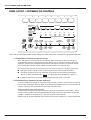
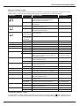
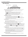
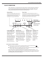
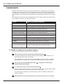
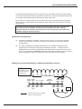
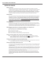
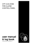
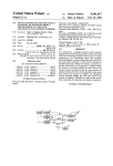
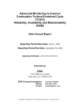
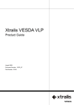
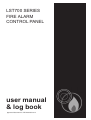
LST700 SERIES FIRE ALARM PANEL
LST700 SERIES
FIRE ALARM
CONTROL PANEL
user manual
& log book
approved document no. DFU7001003 rev 4
LST700 SERIES USER MANUAL • Approved Document No. DFU7001003 Rev 4
1
LST700 SERIES FIRE ALARM PANEL
CONTENTS
Safety ........................................................................................................................................ 3
Important information regarding the safe use of this fire alarm panel
Fire Alarm Systems - An Overview ....................................................................................... 4
How fire alarm systems operate and a general overview of their key features
System Maintenance ............................................................................................................... 5
General guidelines on what the user is expected to do
Panel Layout / Accessing the Controls ................................................................................ 6
A summary of the controls and indicators available on this fire alarm panel, including:Control level definition
How to access the panel’s secure user functions
What the indicators mean
Fire Conditions ....................................................................................................................... 8
How an alarm is indicated, and how to deal with it
How to silence the alarm sounders
How to manually activate the alarm sounders (i.e. to evacuate the building)
How to reset a fire alarm condition
Fault Conditions ..................................................................................................................... 9
The different types of fault that may occur, what they mean and how to deal with them
Disablements ............................................................................................................................ 10
How to inhibit the functionality of certain parts of the fire alarm system
Notes on Delays ....................................................................................................................... 12
Important information about delays, what they mean and what you should do about them
System Set-Up Data Chart .................................................................................................... 13
Details of how the system has been set-up
Log Book .................................................................................................................................. 14
A place for you to record details of events such as fires, false alarms, call outs, etc.
Installation Certificate............................................................................................................. 19
© 2004. Errors & Omissions Excepted. The Manufacturer of this product operates a policy of continuous improvement
and reserves the right to alter product specifications at its discretion and without prior notice. All of the instructions
covered in this manual have been carefully checked prior to publication. However, no responsibility can be accepted by
the Manufacturer for any inaccuracies or for any misinterpretation of an instruction or guidance note by the User.
2
LST700 SERIES USER MANUAL • Approved Document No. DFU7001003 Rev 4
LST700 SERIES FIRE ALARM PANEL
SAFETY
The fire alarm panel is safe to operate provided it has been installed in compliance with the
manufacturers instructions and used in accordance with this manual.
Do not operate the fire alarm panel with its enclosure open. There is no need to open
the enclosure except to carry out commissioning, maintenance and remedial work.
This work must only be carried out by competent service personnel who are fully
conversant with the contents of the separate engineering manual for this product and
have the necessary skills for maintaining this equipment.
If the enclosure is damaged in any way, expert advice should be sought regarding its repair.
Regular servicing of the fire alarm system is highly recommended, preferably on a continuous
maintenance contract and by a competent organisation. A full-itemised report of the installation
should be obtained at least annually.
This product has been manufactured in conformance with the requirements of the
Australian Communications Authority and all applicable EU Council Directives.
N219
LST700 SERIES USER MANUAL • Approved Document No. DFU7001003 Rev 4
3
LST700 SERIES FIRE ALARM PANEL
FIRE ALARM SYSTEMS - AN OVERVIEW
The primary purpose of a fire alarm system is to provide early warning of a fire so that building
occupants can be evacuated and action taken to stop the fire as soon as possible - all according
to a predetermined plan.
Alarms may be raised automatically, by smoke or heat detectors, or manually by a person operating
a manual call point.
To ensure an alarm is dealt with in an orderly manner, it is important to know where the alarm is
coming from. To aid this function, fire alarm systems are usually split into zones, each covering a
different area of a building.
When an alarm has been raised, the fire alarm panel responds by indicating the zone in which the
alarm has occurred and activating all relevant sounders, bells and other alarm outputs to provide a
warning of the fire. Additional alarm outputs available on this fire alarm panel (which may or may
not be used depending on the requirements of the site) are:■
A Remote Output: this output is automatically activated whenever the fire panel is in alarm and
is returned to normal when the alarm sounders are silenced.
■
An Auxiliary Output: this output is activated when the panel is in alarm and is returned to
normal when the panel is reset. It may be used to signal an alarm condition to other parts
of the fire alarm system. If used, its function will be declared on the System Set-up Data
Chart on page 13 of this user manual. This output may be disabled if required.
The building’s fire management plan should always be executed when the fire alarm panel goes into
alarm. See user responsibilities section on page 5 for further details.
Fault monitoring
For obvious reasons, the reliability of the fire alarm system is paramount. To this end, the fire
alarm panel continuously monitors all connections between detectors, manual call points and
sounders and also checks its own power supply and back-up batteries for faults.
If a fault is detected anywhere on the system, the panel responds by illuminating one or more of
the fault light(s) located on the front of its enclosure and sounding its internal fault buzzer. The
panel’s fault output is also activated, sending notification of the fault (if connected) to a remote
manned monitoring centre or other electronic equipment, as required.
Delays
Certain zones on a fire alarm system can be prone to conditions that lead to frequent and unavoidable false alarms, a common example being a waiting room filled with cigarette smoke. In
areas such as these, it may be acceptable to delay the activation of the alarm sounders and other
outputs to give a responsible person time to investigate the cause of the alarm. If the cause is found
to be a true fire hazard, the delay can be overridden. In the event of a false alarm, the panel can be
reset. Should the delay period expire without any user intervention, the alarm sounders will automatically sound to evacuate the premises. To ascertain if any delays have been programmed into the
panel, refer to the System Set-up Data Chart on page 13.
Disablements
In abnormal conditions, certain parts of the fire alarm system can be temporarily turned off (disabled) to suit prevailing conditions. For example, if there is a risk of a false alarm occurring in a
zone, say from vehicle exhaust smoke in a loading bay, it is possible to disable that zone during
the risk period, then enable it again afterwards. Another example is the disablement of outputs
during a routine test or temporary fault.
Coincidence
This feature should only be used where it is acceptable to the Authority Having Jurisdiction. The
function is intended to control the effects of a false alarm but only when this is likely to have a
significant impact, such as the activation of fire suppression systems.
4
LST700 SERIES USER MANUAL • Approved Document No. DFU7001003 Rev 4
LST700 SERIES FIRE ALARM PANEL
SYSTEM MAINTENANCE
AS1670.1 - 2004 Fire Detection Systems design, installation and commissioning and AS18551.8 set
out criteria to ensure that systems are correctly placed into service and then maintained in a fully
operational state.
At the end of this manual we have included an Installer ’s Statement and Commissioning Report which
should be completed for each system. These documents provide essential information which will
assist with the ongoing testing and maintenance of the installation.
Highlighted below are key recommendations on steps which should be taken to ensure the
installation is in a fully operational state at all times.
User responsibilities:
1
2
Check the Fire Indicator Panel system weekly to ensure the system is free of faults and is
capable of activation when an alarm is inititated. Refer to weekly testing below.
Ensure arrangements are in place for the test, maintenance and regular servicing of the
system. Important: AS1851.8 recommends weekly and monthly tests that should be
carried out by the user/responsible person - please refer to the bottom of this page for further details.
3
4
5
6
7
8
9
Ensure the system log book is kept up to date by recording fire signals, fault signals, work on
the system, etc, and make sure it is available for inspection at all times.
Ensure that all relevant occupants of the protected premises are instructed in the proper use
of the system.
Take steps to limit the number of false alarms on the system.
Ensure the effectiveness of the system is not impaired by ensuring there is a space of at
least 500mm in all directions around and below every fire detector and that all manual
call points are unobstructed and easy to see.
Liaise with all relevant building engineers, decorators, etc., to ensure any changes to
(or maintenance of), the building’s fabric does not compromise the protection given by the
fire alarm system, create faults or false alarms.
Ensure that any structural or occupancy changes planned for the building are done so with due
and early consideration given to any changes that may be required to the fire system.
Ensure that a selection of spare parts are held as appropriate within the premises.
Routine weekly and monthly testing to be undertaken by the user/responsible person
We recommend that the following tests are carried out at approximately the same time each week,
during normal working hours:Note: It is essential any alarm receiving centre is contacted before and after these tests to avoid
unwanted alarms and to confirm the fire signal is correctly received.
•
•
•
•
•
•
Carry out an Indicator lamp test to check all zone lights show and the beeper sounds.
Operate a manual call point or smoke/heat detector to test the fire alarm.
Check that the alarm sounders operate.
Reset the system by pressing the Silence/Activate Sounders button and Control Panel Reset button.
Verify that no manual call points or smoke/heat detectors are obstructed in any way.
Test a different zone each week using a different call point or detector so all are tested in rotation.
Monthly attention: Ensure authorized service personnel verify the system’s standby power
supply (or supplies) are in good working order.
Quarterly and periodic inspection, testing, servicing and maintenance
It is the user’s responsibility to ensure that an ongoing inspection and maintenance contract is in
place to meet the requirments of AS1851.8. The work required must be carried out by a competent
person with specialist knowledge of fire detection and alarm systems. The standard recognises
this will normally be an outside specialist fire alarm servicing organization.
Please note: It is good practice to inspect the system on an annual basis to confirm that it is in a fully operational
state. This should include testing all sounders to ensure that they are providing the correct level of sound
generation. Australian Standards require that detectors are fully tested at least every two years. However it is
also essential to regularly identify and clean dirty detectors which are outside manufacturer specification.
LST700 SERIES USER MANUAL • Approved Document No. DFU7001003 Rev 4
5
LST700 SERIES FIRE ALARM PANEL
PANEL LAYOUT / ACCESSING THE CONTROLS
1
2
3
Silence Inter nal
sounder
Silence/Activate
sounders
4
5
8
Fire Zones
2
3
4
5
6
7
8
1
2
3
4
5
6
7
8
fault
output
status
remote
output
status
Zone fault/disabled/test
supply remote
present output
I
7
1
Contr ol Panel
Reset
Enable/
Disable
6
test
accessed
general
disablement
O
Lamp
test
general power system repeater
supply fault
fault
fault
fault
sounder auxiliary output
status output delays
status
Two levels of control are available to the User(s) of this fire alarm panel - General User and Authorised User.
1. General User Controls (access level one)
When the panel is in access level one, the indicator lights on the front of the enclosure give a
comprehensive overview of the system’s current status. Any fire and fault conditions are clearly
displayed, disablements highlighted and the status of all outputs reported. For detailed descriptions of what each indicator means, please refer to the table on the opposite page.
The only functions that can be performed by the user when the panel is in access level one are:■
Muting the panel’s internal sounder by pressing the Silence Internal Sounder button;
■
Overriding any delays which may have been programmed into the panel by pressing the
Silence / Activate Sounders button
(only applicable when the panel is in alarm); or
■
Putting the panel into access level two (the Authorised User state) - see below.
2. Authorised User Controls (access level two)
To avoid unauthorised changes to critical parts of the fire alarm system, controls such as silencing
the sounders, resetting an alarm condition and implementing disablements are only accessible via
a secure method of entry which puts the panel into access level two.
To put the panel into access level two:Turn the key to the I position (please note the key cannot be removed when in this position). When
the key is in the I position, the Accessed light will be lit steady to show the user that the controls are
operative. To leave the access level two, turn the key back to the O position
Details of how to use the Authorised User controls can be found on pages 8 to 11 of this User Manual.
6
LST700 SERIES USER MANUAL • Approved Document No. DFU7001003 Rev 4
LST700 SERIES FIRE ALARM PANEL
What the Indicators mean
The table below summarises the various indicators available on the Fire Alarm Panel and what they mean in their
various States. The final column highlights the page(s) you should turn to for further information.
INDICATOR
(General Fire)
Fire Zones
STATUS OF LIGHT
WHAT THIS MEANS
FURTHER READING
Flashing Red
The Panel has detected a fire alarm condition
or the Activate Sounders button has been
pressed to evacuate the building
Page 8 (Fire Conditions)
Steady Red
There is a silenced fire alarm condition
on the system.
Page 8 (Fire Conditions)
Flashing Red
A fire alarm condition has been detected on
the zones which are flashing
Page 8 (Fire Conditions)
Steady Red
There is a silenced fire alarm condition on
the zones which are lit steady
Page 8 (Fire Conditions)
1 to 8
Zone fault/disabled/test Flashing Yellow
Faulty wiring has been detected on the zones
(in sync. with the which are flashing
1 to 8
gen. fault indicator
Flashing Yellow
(in sync. with the
Test indicator)
Page 9 (Fault Conditions)
The zones which are flashing are in test mode
Steady Yellow
The zones which are lit steady have been disabled Page 10 (Disablements)
supply present
Steady Green
The panel is supplied with power
Page 4 (Overview)
remote output
Steady Red
The remote output has been activated
Page 4 (Overview)
test
Flashing Yellow
The panel is in test mode
accessed
Flashing Yellow
The access code is in the process of being entered Page 6 (Accessing the Controls)
Steady Yellow
The panel is in access level two
Page 6 (Accessing the Controls)
general disablement
Flashing Yellow
The panel is in the disablement selection state
Page 10 (Disablements)
Steady Yellow
Part of the system has been manually disabled
and/or one or more of the fire zones have had
a delay applied to them
Page 10 (Disablements)
Page 12 (Notes on Delays)
Flashing Yellow
Faulty wiring has been detected on the fault
output’s transmission path
Page 9 (Fault Conditions)
Steady Yellow
The fault output has been disabled
Page 10 (Disablements)
Flashing Yellow
Faulty wiring has been detected on the remote
output’s transmission path
Page 9 (Fault Conditions)
Steady Yellow
The remote output has been disabled
Page 10 (Disablements)
general fault
Flashing Yellow
A fault has been detected on the system
Page 9 (Fault Conditions)
power supply fault
Flashing Yellow
The panel has detected a fault with its power
supply, battery charger or back-up batteries
Page 9 (Fault Conditions)
fault output status
remote output status
system fault
Flashing Yellow
The panel has detected a microprocessor fault
Page 9 (Fault Conditions)
repeater fault
Flashing Yellow
The panel has detected a wiring/communication
fault on the repeater network
Page 9 (Fault Conditions)
sounder status
Flashing Yellow
Faulty wiring has been detected on the panel’s
sounder circuits
Page 9 (Fault Conditions)
Steady Yellow
The alarm sounders have been disabled
Page 10 (Disablements)
auxiliary output status
Steady Yellow
The panel’s auxiliary output has been disabled
Page 10 (Disablements)
Flashing Yellow
Faulty wiring has been detected on the auxiliary
output’s transmission path
Page 9 (Fault Conditions)
Steady Yellow
Delays have been programmed into the panel
Page 12 (Notes on Delays)
Flashing Yellow
A delay is running
Page 12 (Notes on Delays)
output delays
Testing the Indicator Lights
To test the panel’s indicator lights are working correctly, press the Lamp Test button
when the panel is in the
Accessed state. The panel’s internal beeper will also sound when pressing the button to show it is working correctly.
LST700 SERIES USER MANUAL • Approved Document No. DFU7001003 Rev 4
7
LST700 SERIES FIRE ALARM PANEL
FIRE CONDITIONS
General Fire Light
Fire Zone Lights
Fire Zones
1
2
3
4
5
6
7
8
When the fire alarm panel receives an alarm trigger from a detector or manual call point located in a
zone that is not already in a fire state, it will:■
Flash the general fire and appropriate fire zone light(s) on the front of its enclosure.
■
Sound its internal sounder.
■
Start the alarm sounders and outputs including, if enabled, the remote output
(provided there are no delays applicable to the zone which is in alarm).
At this point the building’s fire management plan should be executed.
Important Note: Zones which have been disabled cannot be triggered into an alarm
condition (see page 10 for further information on disablements).
Silencing the alarm sounders
■
The alarm sounders may be silenced by putting the panel into access level two and
momentarily pressing the Silence / Activate Sounders button
.
The alarm sounders and the panel’s internal sounder will cease to sound and the light(s) for the
zone(s) in alarm and the red general fire light will be lit steady. All other alarm outputs (i.e. the
remote and auxiliary fire outputs) will remain asserted.
New zone In alarm
Should a new zone be triggered into alarm whilst the alarm sounders are silenced, the panel will:■
Automatically reactivate the alarm sounders
■
Flash the general fire and appropriate fire zone light(s) for any new zone(s) in alarm
■
Keep the light(s) for the previous zone(s) in fire lit steady
Manually activating the alarm sounders (i.e to evacuate the building)
■
Momentarily pressing the Silence / Activate Sounders button
when the panel is in access
level two (see page 6) will cause the alarm sounders to sound. Note: The panel’s remote and
auxiliary fire outputs will not be triggered when the building is manually evacuated in this way.
Pressing the Silence / Activate Sounders button again
will silence the alarm sounders.
NB: If the sounders have been disabled, pressing the Silence/Activate Sounders button will have no effect.
Resetting the panel
■
After the cause of the alarm has been investigated and cleared and the alarm sounders have
been silenced, the panel can be reset by pressing the Control Panel Reset button
.
Fire alarm systems which are directly monitored by a Fire Brigade may only be reset and silenced
by the Fire Service personnel attending an alarm. Users who interfere with monitored systems
which are in alarm may be subject to heavy fines.
The Panel will give a double beep to indicate the reset process has started and, after a few
seconds, the zone fire and general fire lights will go out to indicate the process is complete. If
there are still alarm triggers on any zone the panel will go back into alarm as before.
Exitting access level two
To exit access level two at any time, press the Exit Access Mode button (or, on the keywsitch
version of the panel, turn the key back to the O position).
8
LST700 SERIES USER MANUAL • Approved Document No. DFU7001003 Rev 4
LST700 SERIES FIRE ALARM PANEL
FAULT CONDITIONS
When a fault occurs on a critical part of the fire alarm system, the panel responds by activating its
internal sounder and illuminating the general fault light and any other fault light(s) relating to the
fault. The panel’s fault output will also activate (provided it hasn’t been disabled). The type of
faults typically indicated at the fire alarm panel are described below:-
General Fault
Zone Fault
The general fault light flashes when there is a
fault on any part of the fire alarm system. It
is always lit in tandem with at least one other
fault light which conveys more precise
information on the type of fault detected.
The relevant zone fault light flashes when there is a
wiring problem on a zone or a detector has been removed
from its base. It should be noted that any alarms raised on
the faulty zone(s) may not be recognised by the fire alarm
panel until the fault condition has been cleared.
1
2
supply remote
present output
test
3
accessed
4
5
6
general
disablement
general power system repeater
fault
supply fault
fault
fault
7
8
fault
output
status
remote
output
status
Fault Output,
Remote Output or
Auxiliary Output
Fault
Flashes when a wiring
fault has been detected
on the lit output’s
transmission path.
sounder auxiliary output
status output delays
status
Power Supply Fault
System Fault
Repeater Fault
Sounder Fault
The power supply fault
light flashes when the mains
supply has failed, or the
standby batteries or its
charger are faulty.
If the mains supply fails, the
panel will only operate for
the standby period dictated
by the size of the batteries
fitted. If the batteries or
charger fail at the same
time as the Mains, the
Panel will be inoperative.
The system fault light flashes
when the panel’s microprocessor has reset, typically after
excessive electrical interference,
or if the contents of its memory
have been corrupted. This fault
can only be cleared by pressing
the Control Panel Reset button
. If the fault re-occurs
within two minutes, this is
indicative of a corrupt memory
and expert advice should be
sought.
The repeater fault
light flashes when
the connection
between a repeater
panel (if fitted) and
the master panel
fails. Depending
on where the fault
has occurred, some
or all of the
repeaters may no
longer operate
correctly.
The Sounder
Status light flashes
when there is a
wiring fault on the
sounder circuits.
Depending on
where the fault has
occurred, one or
all of the alarm
sounders may no
longer be
operative.
In the event of a fault condition
■
Mute the panel’s internal sounder by pressing the Silence Internal Sounder button
(The panel does not have to be in access level two to do this).
■
Note the fault(s) down in the Log Book at the back of this manual and take appropriate action to
correct it / them. See User Responsibilities section on page 5.
When a fault has been rectified the indicator light for that fault is automatically turned off. If all
faults are cleared, the general fault light will go out, and the panel’s internal sounder will be silent (if
not already muted). If the fire alarm panel is reset any existing fault(s) will reappear as before and
the silencing process will have to be repeated.
LST700 SERIES USER MANUAL • Approved Document No. DFU7001003 Rev 4
9
LST700 SERIES FIRE ALARM PANEL
DISABLEMENTS
Certain fire alarm panel functions can be temporarily disabled (i.e. switched off) to suit prevailing
conditions. For example, if there is a risk of a false alarm in a zone, say from vehicle exhaust smoke
in a loading bay, it is possible for the user to disable that zone during the risk period and enable it
again afterwards. Another example is the disablement of outputs during a routine test or temporary
fault.
Following is a list of options that may be disabled by the user at the fire alarm panel and the effect
their disablement will have on how the system works:-
OPTION
EFFECT ON SYSTEM WHEN DISABLED
Zone 1
Alarms and faults on zone 1 will not be processed
Zone 2
Alarms and faults on zone 2 will not be processed
Zone 3 (only available if fitted)
Alarms and faults on zone 3 will not be processed
Zone 4 (only available if fitted)
Alarms and faults on zone 4 will not be processed
Zone 5 (only available if fitted)
Alarms and faults on zone 5 will not be processed
Zone 6 (only available if fitted)
Alarms and faults on zone 6 will not be processed
Zone 7 (only available if fitted)
Alarms and faults on zone 7 will not be processed
Zone 8 (only available if fitted)
Alarms and faults on zone 8 will not be processed
Fault output
Faults will not be transmitted to any other equipment (if fitted)
Remote output
Alarms will not be transmitted to remote equipment (if fitted)
Sounders
The alarm sounders will not operate in a fire condition
Auxiliary output
Alarms will not be transmitted to local fire fighting equipment (if fitted)
Output delays (only available
if delays have been programmed
into the panel by an engineer)
If this option is available, please refer to page 12 for important
information regarding delays before attempting to alter this
function
To disable or enable any of the above options
Put the fire alarm panel into access level two (see page 6).
1
Start the selection process by pressing the Next Option button
.
The general disablement light will flash and the fault light relating to the first option in the
above table will flash to show it is selected.
If the light flashes at a slower rate than the general disablement light, the option is enabled
If the light flashes at the same rate as the general disablement light, the option is disabled
2
If necessary, press the Enable/Disable button
between disabled and enabled.
to toggle the selected option
3
To confirm your choice, press the Next Option button
.
This will move the selection process on to the next available option in the above table and the
fault light relating to this new option will flash to show it is selected.
The previous option’s fault light will now be lit steady to confirm it is disabled or switched off to
confirm it is enabled.
4
10
Repeat steps 2 & 3 for every available option until the selection process is complete.
LST700 SERIES USER MANUAL • Approved Document No. DFU7001003 Rev 4
LST700 SERIES FIRE ALARM PANEL
The disablement/enablement process is complete when all available options have been selected
in turn and the Next Option button is pressed for the last time. At this point all disabled options will
be lit steady and all enabled options will have their lights switched off.
To save time, the selection process can be exited at any time by pressing the Exit Access Mode
button (the only changes that will be saved will be those made prior to the last press of the Next
Option button)
To avoid confusion, during the selection process any light in the table of options that
was showing a fault Condition will have the fault indication turned off. After the
selection process is complete, fault indication will be restored unless that option was
disabled during the selection process.
Notes about disablements
(a)
The option of disabling or enabling zones 3 & 4 and zones 5, 6, 7 & 8 is only available
if these zones are fitted. If they are not fitted, the selection process will skip to the next
available option.
(b)
The option of disabling or enabling output delays is only available if delays have been
programmed into the fire alarm panel by the installation engineer. If a delay has been
programmed into the panel the output delays light will be lit when the panel is in the normal
(i.e. non-accessed) state. Important: Please refer to the ‘Notes on Delays’ section on Page 12
before proceeding to make any changes to the way the delays function operates.
Diagram to show the disablement / enablement selection sequence
START (Panel in
accessed state and
Next Option button
pressed once)
1
2
3
4
5
6
7
8
fault
output
status
remote
output
status
Zone fault/disabled/test
supply remote
present output
test
accessed
general power system repeater
fault
supply fault
fault
fault
general
disablement
sounder auxiliary output
status output delays
status
END
indicates option only available
if fitted or programmed
LST700 SERIES USER MANUAL • Approved Document No. DFU7001003 Rev 4
11
LST700 SERIES FIRE ALARM PANEL
NOTES ON DELAYS
What is a delay?
A delay can be programmed into the fire alarm panel to postpone the activation of the alarm
sounders and other outputs for a predetermined length of time. The delay period gives a responsible person time to investigate the cause of an alarm, usually in areas which are prone to false
alarm (such as waiting rooms filled with smoke) before the building is evacuated. If the cause of
the alarm is found to be a true fire hazard, the delay can be overridden and the alarm sounders
activated immediately. Alternatively, in the case of a false alarm, the panel can be reset.
Delay options
One, some or all of the zones on the fire alarm panel can have a delay applied to them to suit the
requirements of the site. The same delay period applies to all delayed zones and is adjustable to
a maximum of 10 minutes. The programming of delays must only be carried out by competent
service personnel who are advised to record all relevant delay data on the System Set-up Data
Chart on page 13 of this user manual. Delays should only be used with the prior knowledge and
consent of all relevant authorities i.e fire officer, building control, etc.
Delay indication
If delays have been programmed into the panel the Output Delays light and the general disablement light will be lit steadily. This means the immediate turning on of the alarm sounders and other
outputs on one or more zones has been disabled. The only way to ascertain which
zones have been programmed with a delay is to refer to the System Set-Up Data Chart on page 13.
What happens when there is a fire alarm condition on a delayed zone?
Should an alarm occur on a delayed zone, the panel will:■
Flash its general fire and appropriate fire zone light(s)
■
Sound its internal sounder
■
Start the delay countdown sequence
■
Indicate a delay is running by flashing its Output Delays light
How to override a delay in the event of a true fire alarm condition
■
If, on investigation, the cause of the alarm on the delayed zone is found to be a true fire
hazard, pressing the Silence / Activate Sounders button
at any time will override the
delay and activate the alarm sounders and outputs with immediate effect.
How to reset the system in the event of a false alarm
■
If, on investigation, the cause of the alarm is found to be false, put the panel into access level
two (see page 6) and press the Control Panel reset button
.
How to turn the delays function on or off
Any delays that have been programmed into the panel can be turned on or off by putting the panel
into access level two and following the disablement / enablement selection process as described
on pages 10 and 11.
Selecting the Output Delays option and then pressing the Enable/Disable button so that the Output
Delays light flashes in synchronisation with the general disablement light shows that the delays are on.
Pressing the Enable/Disable button again will make the Output Delays light flash slower than the
general disablement light, showing that the delays are off.
Having chosen the desired setting, pressing the Next Option button will exit the disablement /
enablement selection process . The Output Delays light will now be lit steadily with the general
disablement light, showing that delays are on, or the Output Delays light will be off, showing that
delays are off.
12
LST700 SERIES USER MANUAL • Approved Document No. DFU7001003 Rev 4
LST700 SERIES FIRE ALARM PANEL
SYSTEM SET-UP DATA CHART
Important: This page should be carefully completed by an authorised engineer prior to system hand-over.
FIRE ZONE INFORMATION
ZONE
NUMBER
ZONE DESCRIPTION
A concise explanation of the rooms and areas contained in each Zone
DELAY
APPLIED?
1
Yes/No
2
Yes/No
3
Yes/No
4
Yes/No
5
Yes/No
6
Yes/No
7
Yes/No
8
Yes/No
COINCIDENCE
(tick if selected)
LENGTH OF DELAY (1 TO 10 MINUTES) IF APPLICABLE
OUTPUT ROUTING INFORMATION
TYPE OF OUTPUT
CONNECTED?
REMOTE OUTPUT
Yes/No
AUXILIARY OUTPUT
Yes/No
FAULT OUTPUT
Yes/No
RESET OUTPUT
Yes/No
WHAT HAPPENS WHEN ACTIVATED?
ADDITIONAL INFORMATION
Any additional information the user needs to know should be entered in this box including repeater location, the
routing of any additional outputs, details of any inputs utilised, etc.
THE INFORMATION ABOVE WAS COMPLETED BY (name) _______________________________
OF (company) _________________________________________ ON (date) __________________
NOTES ON COINCIDENCE: The following applies to all pairs of zones which are set up for coincidence.
There must be alarms on both zones (i.e. zone 1 and zone 2) before the alarm sounders and outputs turn on. If
only one of the zones (i.e. zone 1) goes into alarm, the panel indicates the alarm by illuminating the relevant
indicator on the front of its enclosure and sounding its internal sounder, thus prompting the user to investigate.
If found to be false, the alarm can be reset or, if found to be a true fire condition, the sounders can be manually
activated by pressing the “Silence/Activate Sounders” button - as detailed on page 8.
LST700 SERIES USER MANUAL • Approved Document No. DFU7001003 Rev 4
13
LST700 SERIES FIRE ALARM PANEL
FIRE ALARM LOG BOOK
It is recommended that a log book be kept on all sites and that it be maintained by a responsible person, who should
ensure that all entries are properly recorded. This is necessary to satisfy the requirements of AS1670.1 and noncompliance may be an offence. It is also essential to record all maintenance and testing in accordance with the
provisions of AS1851.8. Failure to comply with these basic requirements may present significant problems if an event
occurs and the history of the system is not available. We recommend the following details and events be recorded:
■
■
■
■
■
■
■
■
■
The name of the responsible person;
Brief details of the maintenance arrangements;
Dates and times of all tests, including fire drills;
Dates and times of all fires to which the system responds;
Dates and times of all false alarms;
Causes, circumstances surrounding, and category of false alarms (if known);
The identity of any manual call point or fire detector that triggers any of the above fire alarm signals (if known);
Dates, times and type of all faults and defects.
Dates and times of all maintenance (e.g service visit or non-routine attention).
USER:
SITE ADDRESS:
RESPONSIBLE PERSON(S) ON SITE:
THE SYSTEM WAS DESIGNED BY:
THE SYSTEM WAS INSTALLED BY:
THE SYSTEM WAS COMMISSIONED BY:
THE SYSTEM WAS ACCEPTED BY:
VERIFICATION WAS UNDERTAKEN BY:
FOR SERVICE (DETAILS OF WHO YOU SHOULD CONTACT IF MAINTENANCE IS REQUIRED)
THE SYSTEM IS MAINTAINED UNDER CONTRACT BY:
Company: _______________________________________________________________________________
Address: _______________________________________________________________________________
______________________________________________________________________________________
Contact No: __________________________________________
Expiry Date: ______________________
NORMAL HOURS (MON-FRI) TEL: ____________________________________________________________
OUTSIDE NORMAL HOURS TEL: ___________________________________________________________
MANNED CENTRE TEL: ___________________________________________________________________
MANNED CENTRE CODE: _________________________________________________________________
THE NORMAL MAXIMUM ATTENDANCE TIME FOR A MAINTENANCE TECHNICIAN IS: _______________
EXPENDABLE COMPONENT REPLACEMENT PERIODS (LIST):-
14
LST700 SERIES USER MANUAL • Approved Document No. DFU7001003 Rev 4
LST700 SERIES FIRE ALARM PANEL
Details of tests (including fire drills), actual fire alarms, disablements or enablements and faults should be
recorded here. False alarms and maintenance work should be recorded on page 18.
DATE
TIME
EVENT e.g. test, fire alarm signal, fault
ZONE
DEVICE
LST700 SERIES USER MANUAL • Approved Document No. DFU7001003 Rev 4
ACTION REQUIRED
COMPLETED INITIALS
15
LST700 SERIES FIRE ALARM PANEL
DATE
16
TIME
EVENT e.g. test, fire alarm signal, fault
ZONE
DEVICE
ACTION REQUIRED
COMPLETED INITIALS
LST700 SERIES USER MANUAL • Approved Document No. DFU7001003 Rev 4
LST700 SERIES FIRE ALARM PANEL
DATE
TIME
EVENT e.g. test, fire alarm signal, fault
ZONE
DEVICE
LST700 SERIES USER MANUAL • Approved Document No. DFU7001003 Rev 4
ACTION REQUIRED
COMPLETED INITIALS
17
LST700 SERIES FIRE ALARM PANEL
False alarms
DATE
TIME
ZONE
DEVICE THAT
TRIGGERED THE
ALARM SIGNAL
CAUSE
(IF KNOWN)
BRIEF CIRCUMSTANCES
(WHERE CAUSE IS UNKNOWN,
RECORD ACTIVITIES IN THE AREA)
MAINTENANCE
VISIT REQUIRED?
(YES OR NO)
FINDINGS OF
MAINTENANCE
TECHNICIAN
CATEGORY
OF FALSE
ALARM
FURTHER
ACTION
REQUIRED
DONE
PLEASE
TICK
Maintenance work
DATE
18
TIME
ZONE
DEVICE
(WHERE APPLICABLE) (WHERE APPLICABLE)
REASONS FOR WORK
WORK CARRIED OUT
FURTHER WORK
REQUIRED
SIGNATURE
LST700 SERIES USER MANUAL • Approved Document No. DFU7001003 Rev 4
LST700 SERIES FIRE ALARM PANEL
Certificate
of INSTALLATION
for the fire alarm system at:
1.
Name of premises .....................................................................................................................................
2.
Situated at .................................................................................................................................................
..............................................................................................................................................................
..............................................................................................................................................................
3.
I/We have installed in the above premises
An alteration to the system of ......................................................................................................
A system of .....................................................................................................................................
(Brand name)
4.
The system is connected to the ................................................................... monitoring service provider
5.
The system incorporates the following ancillary equipment ........................................................................
..............................................................................................................................................................
..............................................................................................................................................................
6.
The quiescent load of ancillary equipment is .......................................................................................
7.
Primary power voltage and source .......................................................................................................
8.
Secondary battery type and capacity ...........................................................................................................
9.
System maintenance agreement details ...................................................................................................
10.
Portion/s of premises not protected by this system ..................................................................................
..............................................................................................................................................................
..............................................................................................................................................................
11.
I/We hereby certify that:
(a)
(b)
(c)
The installation is complete and has been thoroughly tested.
The system is installed in accordance with the current requirements of AS 1670.1*.
The system is installed in accordance with the attached design specification*.
Except in regard to the following details* .............................................................................................................
...........................................................................................................................................................................
...........................................................................................................................................................................
which have been approved by .............................................................................................................. (person)
of ....................................................................................................................................................... (organization)
* Strike out the words that are not applicable.
Location of the fire indicator panel ....................................................................................................................
PLEASE ALSO COMPLETE THE INFORMATION OVERLEAF
LST700 SERIES USER MANUAL • Approved Document No. DFU7001003 Rev 4
19
LST700 SERIES FIRE ALARM PANEL
CONTINUED FROM PREVIOUS PAGE
Zone of
Protection
Alarm
zone
Number and type of actuating devices
Number of
actuating
devices
per zone*
Heat
A
B
C
Fire
D
E
Smoke
Flame
CO
IR
UV
Manual
Call
Point
Other
Zone 1
Zone 2
Zone 3
Zone 4
Zone 5
Zone 6
Zone 7
Zone 8
Total
number
* Indicate with a number in brackets the number of actuating devices in concealed spaces.
Additional information ..................................................................................................................................................
......................................................................................................................................................................................
........................................................................................................................................................................................
.....................................................................................................................................................................................
Name ................................................................................. Signature ........................................................................
Company .......................................................................................................... Date ...............................................
20
LST700 SERIES USER MANUAL • Approved Document No. DFU7001003 Rev 4