1
NBG6716
Simultaneous Dual-Band Wireless AC1750 HD Media Router
Version 1.00
Edition 1, 06/2013
Quick Start Guide
User’s Guide
Default Login Details
LAN IP Address
http://192.168.1.1
(Router Mode)
http://192.168.1.2
www.zyxel.com
(Access Point Mode)
Password
1234
Copyright © 2013 ZyXEL Communications Corporation
IMPORTANT!
READ CAREFULLY BEFORE USE.
KEEP THIS GUIDE FOR FUTURE REFERENCE.
Screenshots and graphics in this book may differ slightly from your product due to differences in
your product firmware or your computer operating system. Every effort has been made to ensure
that the information in this manual is accurate.
Related Documentation
• Quick Start Guide
The Quick Start Guide shows how to connect the NBG6716 and access the Web Configurator
wizards. It contains information on setting up your network and configuring for Internet access.
2
NBG6716 User’s Guide
Contents Overview
Contents Overview
User’s Guide .......................................................................................................................................13
Introduction .............................................................................................................................................15
Connection Wizard ..................................................................................................................................21
Introducing the Web Configurator ...........................................................................................................31
NBG6716 Modes .....................................................................................................................................35
Easy Mode ..............................................................................................................................................37
Router Mode ...........................................................................................................................................49
Access Point Mode .................................................................................................................................57
Tutorials ..................................................................................................................................................65
Technical Reference ..........................................................................................................................77
Monitor ....................................................................................................................................................79
WAN ........................................................................................................................................................85
Wireless LAN ..........................................................................................................................................93
LAN ....................................................................................................................................................... 117
DHCP Server ........................................................................................................................................121
NAT .......................................................................................................................................................127
DDNS ....................................................................................................................................................137
Static Route ...........................................................................................................................................139
Firewall ..................................................................................................................................................143
Content Filtering ....................................................................................................................................149
StreamBoost Management ...................................................................................................................153
Remote Management ............................................................................................................................161
Universal Plug-and-Play (UPnP) ...........................................................................................................165
USB Media Sharing ...............................................................................................................................171
Maintenance ..........................................................................................................................................181
Troubleshooting ....................................................................................................................................191
NBG6716 User’s Guide
3
Contents Overview
4
NBG6716 User’s Guide
Table of Contents
Table of Contents
Contents Overview ..............................................................................................................................3
Table of Contents .................................................................................................................................5
Part I: User’s Guide ......................................................................................... 13
Chapter 1
Introduction.........................................................................................................................................15
1.1 Overview ...........................................................................................................................................15
1.1.1 Dual-Band ................................................................................................................................16
1.2 Applications .......................................................................................................................................16
1.3 Ways to Manage the NBG6716 ........................................................................................................16
1.4 Good Habits for Managing the NBG6716 .........................................................................................17
1.5 Resetting the NBG6716 ....................................................................................................................17
1.5.1 How to Use the RESET Button ................................................................................................17
1.6 The WPS Button ...............................................................................................................................17
1.7 LEDs .................................................................................................................................................18
1.8 Wall Mounting ...................................................................................................................................20
Chapter 2
Connection Wizard .............................................................................................................................21
2.1 Overview ...........................................................................................................................................21
2.2 Accessing the Wizard ........................................................................................................................21
2.3 Connect to Internet ............................................................................................................................22
2.3.1 Connection Type: IPoE ............................................................................................................23
2.3.2 Connection Type: PPPoE ........................................................................................................24
2.4 Router Password ...............................................................................................................................26
2.5 Wireless Security ..............................................................................................................................27
2.5.1 Wireless Security: No Security ................................................................................................27
2.5.2 Wireless Security: WPA2-PSK .................................................................................................28
Chapter 3
Introducing the Web Configurator ....................................................................................................31
3.1 Overview ...........................................................................................................................................31
3.2 Accessing the Web Configurator .......................................................................................................31
3.2.1 Login Screen ...........................................................................................................................31
3.2.2 Password Screen ....................................................................................................................32
NBG6716 User’s Guide
5
Table of Contents
Chapter 4
NBG6716 Modes .................................................................................................................................35
4.1 Overview ...........................................................................................................................................35
4.1.1 Web Configurator Modes .........................................................................................................35
4.1.2 Device Modes ..........................................................................................................................35
Chapter 5
Easy Mode ...........................................................................................................................................37
5.1 Overview ...........................................................................................................................................37
5.2 What You Can Do .............................................................................................................................38
5.3 What You Need to Know ...................................................................................................................38
5.4 Navigation Panel ...............................................................................................................................39
5.5 Network Map .....................................................................................................................................39
5.6 Control Panel ....................................................................................................................................40
5.6.1 Power Saving ..........................................................................................................................40
5.6.2 Content Filter ...........................................................................................................................41
5.6.3 Firewall ....................................................................................................................................42
5.6.4 Internet Setting ........................................................................................................................42
5.6.5 Wireless Security .....................................................................................................................44
5.6.6 WPS ........................................................................................................................................45
5.7 Status Screen in Easy Mode .............................................................................................................46
Chapter 6
Router Mode........................................................................................................................................49
6.1 Overview ...........................................................................................................................................49
6.2 Router Mode Status Screen ..............................................................................................................49
6.2.1 Navigation Panel .....................................................................................................................52
Chapter 7
Access Point Mode.............................................................................................................................57
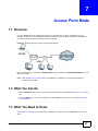
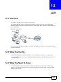
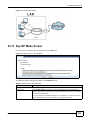
7.1 Overview ...........................................................................................................................................57
7.2 What You Can Do .............................................................................................................................57
7.3 What You Need to Know ...................................................................................................................57
7.3.1 Setting your NBG6716 to AP Mode .........................................................................................58
7.3.2 Accessing the Web Configurator in Access Point Mode ..........................................................58
7.3.3 Configuring your WLAN and Maintenance Settings ................................................................59
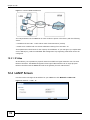
7.4 AP Mode Status Screen ....................................................................................................................59
7.4.1 Navigation Panel .....................................................................................................................61
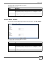
7.5 LAN Screen .......................................................................................................................................61
Chapter 8
Tutorials ...............................................................................................................................................65
8.1 Overview ...........................................................................................................................................65
6
NBG6716 User’s Guide
Table of Contents
8.2 Set Up a Wireless Network with WPS ...............................................................................................65
8.2.1 Push Button Configuration (PBC) ............................................................................................65
8.2.2 PIN Configuration ....................................................................................................................66
8.3 Configure Wireless Security without WPS ........................................................................................67
8.3.1 Configure Your Notebook ........................................................................................................69
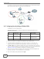
8.4 Using Multiple SSIDs on the NBG6716 .............................................................................................71
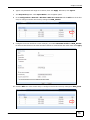
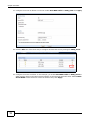
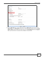
8.4.1 Configuring Security Settings of Multiple SSIDs ......................................................................72
Part II: Technical Reference............................................................................ 77
Chapter 9
Monitor.................................................................................................................................................79
9.1 Overview ...........................................................................................................................................79
9.2 What You Can Do .............................................................................................................................79
9.3 The Log Screen .................................................................................................................................79
9.3.1 View Log ..................................................................................................................................79
9.3.2 Log Setting ..............................................................................................................................80
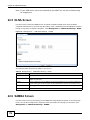
9.4 DHCP Table
...................................................................................................................................80
9.5 Packet Statistics
.............................................................................................................................81
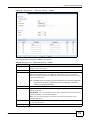
9.6 WLAN Station Status
.....................................................................................................................82
Chapter 10
WAN .....................................................................................................................................................85
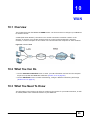
10.1 Overview .........................................................................................................................................85
10.2 What You Can Do ...........................................................................................................................85
10.3 What You Need To Know ................................................................................................................85
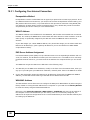
10.3.1 Configuring Your Internet Connection ....................................................................................86
10.4 Internet Connection .........................................................................................................................87
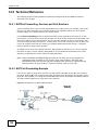
10.4.1 IPoE Encapsulation ...............................................................................................................87
10.4.2 PPPoE Encapsulation ...........................................................................................................89
10.5 Advanced WAN Screen ..................................................................................................................91
Chapter 11
Wireless LAN.......................................................................................................................................93
11.1 Overview .........................................................................................................................................93
11.1.1 What You Can Do ..................................................................................................................94
11.1.2 What You Should Know .........................................................................................................94
11.2 General Wireless LAN Screen .......................................................................................................98
11.3 Wireless Security ...........................................................................................................................100
11.3.1 No Security ..........................................................................................................................100
11.3.2 WEP Encryption ...................................................................................................................101
NBG6716 User’s Guide
7
Table of Contents
11.3.3 WPA-PSK/WPA2-PSK .........................................................................................................103
11.3.4 WPA/WPA2 ..........................................................................................................................104
11.4 More AP Screen ............................................................................................................................106
11.4.1 More AP Edit ........................................................................................................................107
11.5 MAC Filter Screen ........................................................................................................................109
11.6 Wireless LAN Advanced Screen ................................................................................................... 111
11.7 Quality of Service (QoS) Screen ................................................................................................... 111
11.8 WPS Screen .................................................................................................................................. 112
11.9 WPS Station Screen ...................................................................................................................... 114
11.10 Scheduling Screen ...................................................................................................................... 114
Chapter 12
LAN .................................................................................................................................................... 117
12.1 Overview ....................................................................................................................................... 117
12.2 What You Can Do ......................................................................................................................... 117
12.3 What You Need To Know .............................................................................................................. 117
12.3.1 IP Alias ................................................................................................................................ 118
12.4 LAN IP Screen .............................................................................................................................. 118
12.5 IP Alias Screen .............................................................................................................................. 119
Chapter 13
DHCP Server .....................................................................................................................................121
13.1 Overview .......................................................................................................................................121
13.1.1 What You Can Do ................................................................................................................121
13.1.2 What You Need To Know .....................................................................................................121
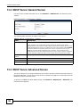
13.2 DHCP Server General Screen ......................................................................................................122
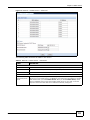
13.3 DHCP Server Advanced Screen
................................................................................................122
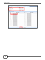
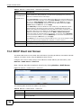
13.4 DHCP Client List Screen ...............................................................................................................124
Chapter 14
NAT.....................................................................................................................................................127
14.1 Overview
....................................................................................................................................127
14.1.1 What You Can Do ................................................................................................................127
14.1.2 What You Need To Know .....................................................................................................128
14.2 General .........................................................................................................................................129
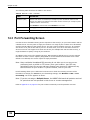
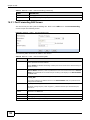
14.3 Port Forwarding Screen ...............................................................................................................130
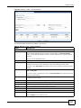
14.3.1 Port Forwarding Edit Screen ..............................................................................................132
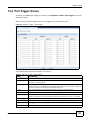
14.4 Port Trigger Screen .......................................................................................................................133
14.5 Technical Reference ......................................................................................................................134
14.5.1 NATPort Forwarding: Services and Port Numbers ..............................................................134
14.5.2 NAT Port Forwarding Example ............................................................................................134
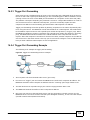
14.5.3 Trigger Port Forwarding .......................................................................................................135
14.5.4 Trigger Port Forwarding Example ........................................................................................135
8
NBG6716 User’s Guide
Table of Contents
14.5.5 Two Points To Remember About Trigger Ports ...................................................................136
Chapter 15
DDNS..................................................................................................................................................137
15.1 Overview ......................................................................................................................................137
15.1.1 What You Need To Know .....................................................................................................137
15.2 General
.......................................................................................................................................137
Chapter 16
Static Route .......................................................................................................................................139
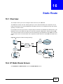
16.1 Overview
....................................................................................................................................139
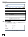
16.2 IP Static Route Screen .................................................................................................................139
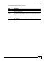
16.2.1 Add/Edit Static Route ..........................................................................................................140
Chapter 17
Firewall ..............................................................................................................................................143
17.1 Overview
.....................................................................................................................................143
17.1.1 What You Can Do ................................................................................................................143
17.1.2 What You Need To Know .....................................................................................................143
17.2 General Screen ............................................................................................................................145
17.3 Services Screen ............................................................................................................................145
Chapter 18
Content Filtering ...............................................................................................................................149
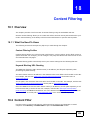
18.1 Overview .......................................................................................................................................149
18.1.1 What You Need To Know .....................................................................................................149
18.2 Content Filter .................................................................................................................................149
18.3 Technical Reference ......................................................................................................................151
18.3.1 Customizing Keyword Blocking URL Checking ...................................................................151
Chapter 19
StreamBoost Management...............................................................................................................153
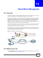
19.1 Overview ......................................................................................................................................153
19.2 What You Can Do .........................................................................................................................153
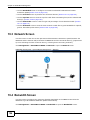
19.3 Network Screen ............................................................................................................................154
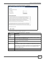
19.4 Banwidth Screen ...........................................................................................................................154
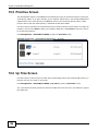
19.5 Priorities Screen ...........................................................................................................................156
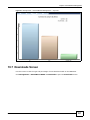
19.6 Up Time Screen ...........................................................................................................................156
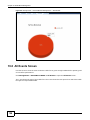
19.7 Downloads Screen .......................................................................................................................157
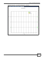
19.8 All Events Screen .........................................................................................................................158
Chapter 20
Remote Management........................................................................................................................161
NBG6716 User’s Guide
9
Table of Contents
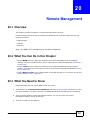
20.1 Overview .......................................................................................................................................161
20.2 What You Can Do in this Chapter .................................................................................................161
20.3 What You Need to Know ...............................................................................................................161
20.3.1 Remote Management and NAT ...........................................................................................162
20.3.2 System Timeout ..................................................................................................................162
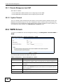
20.4 WWW Screen
.............................................................................................................................162
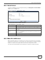
20.5 Telnet Screen
.............................................................................................................................163
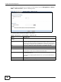
20.6 Wake On LAN Screen ...................................................................................................................163
Chapter 21
Universal Plug-and-Play (UPnP)......................................................................................................165
21.1 Overview ......................................................................................................................................165
21.2 What You Need to Know ...............................................................................................................165
21.2.1 NAT Traversal ......................................................................................................................165
21.2.2 Cautions with UPnP .............................................................................................................165
21.3 UPnP Screen ...............................................................................................................................166
21.4 Technical Reference ......................................................................................................................166
21.4.1 Using UPnP in Windows XP Example .................................................................................166
21.4.2 Web Configurator Easy Access ...........................................................................................168
Chapter 22
USB Media Sharing...........................................................................................................................171
22.1 Overview .......................................................................................................................................171
22.2 What You Can Do .........................................................................................................................172
22.3 What You Need To Know ..............................................................................................................172
22.4 Before You Begin ..........................................................................................................................173
22.5 DLNA Screen ................................................................................................................................174
22.6 SAMBA Screen .............................................................................................................................174
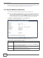
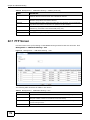
22.7 FTP Screen ...................................................................................................................................176
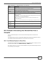
22.8 Example of Accessing Your Shared Files From a Computer ........................................................177
22.8.1 Use Windows Explorer to Share Files .................................................................................177
22.8.2 Use FTP to Share Files .......................................................................................................179
Chapter 23
Maintenance ......................................................................................................................................181
23.1 Overview .......................................................................................................................................181
23.2 What You Can Do .........................................................................................................................181
23.3 General Screen .............................................................................................................................181
23.4 Password Screen ..........................................................................................................................182
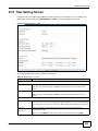
23.5 Time Setting Screen ......................................................................................................................183
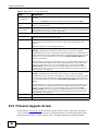
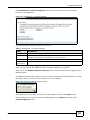
23.6 Firmware Upgrade Screen ............................................................................................................184
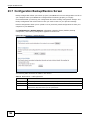
23.7 Configuration Backup/Restore Screen ..........................................................................................186
23.8 Restart Screen ..............................................................................................................................187
10
NBG6716 User’s Guide
Table of Contents
23.9 Language Screen ..........................................................................................................................187
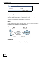
23.10 System Operation Mode Overview .............................................................................................188
23.11 Sys OP Mode Screen ..................................................................................................................189
Chapter 24
Troubleshooting................................................................................................................................191
24.1 Overview .......................................................................................................................................191
24.2 Power, Hardware Connections, and LEDs ....................................................................................191
24.3 NBG6716 Access and Login .........................................................................................................192
24.4 Internet Access .............................................................................................................................193
24.5 Resetting the NBG6716 to Its Factory Defaults ............................................................................195
24.6 Wireless Connections ...................................................................................................................195
24.7 USB Device Problems ...................................................................................................................197
24.8 ZyXEL Share Center Utility Problems ...........................................................................................197
Appendix A Pop-up Windows, JavaScript and Java Permissions ...................................................199
Appendix B Setting Up Your Computer’s IP Address ......................................................................209
Appendix C Common Services........................................................................................................237
Appendix D Legal Information .........................................................................................................241
Index ..................................................................................................................................................247
NBG6716 User’s Guide
11
Table of Contents
12
NBG6716 User’s Guide
P ART I
User’s Guide
13
14
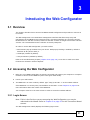
C HAPT ER
1
Introduction
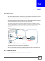
1.1 Overview
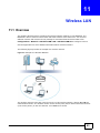
This chapter introduces the main features and applications of the NBG6716.
The NBG6716 extends the range of your existing wired network without additional wiring, providing
easy network access to mobile users. You can set up a wireless network with other IEEE 802.11a/
ac/b/g/n compatible devices.
A range of services such as a firewall and content filtering are also available for secure Internet
computing. The NBG6716 also supports the new StreamBoost technology, which is smart Quality of
Service (QoS), to redistribute traffic over the NBG6716 for the best possible performance in a home
network.
There are two USB 2.0 ports on the side panel of your NBG6716. You can connect USB (version 2.0
or lower) memory sticks, USB hard drives, or USB devices for file sharing. The NBG6716
automatically detects the USB devices.
Two USB eject buttons are located above the USB ports. Push the eject button of the corresponding
USB port for 2 seconds. Make sure the USB LED is off before removing your USB device. This will
remove your USB device safely, preventing file or data loss if it is being transmitted through the
USB device.
Figure 1 USB Ports and Eject Buttons
Eject buttons
USB ports
Note: For the USB function, it is strongly recommended to use version 2.0 or lower USB
storage devices (such as memory sticks, USB hard drives) and/or USB devices
(such as USB printers). Other USB products are not guaranteed to function
properly with the NBG6716.
NBG6716 User’s Guide
15
Chapter 1 Introduction
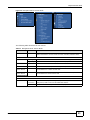
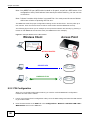
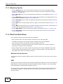
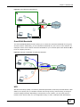
1.1.1 Dual-Band
The NBG6716 is a dual-band AP and able to function both 2.4G and 5G networks at the same time.
You could use the 2.4 GHz band for regular Internet surfing and downloading while using the 5 GHz
band for time sensitive traffic like high-definition video, music, and gaming.
Figure 2 Dual-Band Application
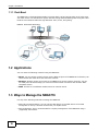
1.2 Applications
Your can have the following networks using the NBG6716:
• Wired. You can connect network devices via the Ethernet ports of the NBG6716 so that they can
communicate with each other and access the Internet.
• Wireless. Wireless clients can connect to the NBG6716 to access network resources. You can
use WPS (Wi-Fi Protected Setup) to create an instant network connection with another WPScompatible device.
• WAN. Connect to a broadband modem/router for Internet access.
1.3 Ways to Manage the NBG6716
Use any of the following methods to manage the NBG6716.
• WPS (Wi-Fi Protected Setup). You can use the WPS button or the WPS section of the Web
Configurator to set up a wireless network with your ZyXEL Device.
• Web Configurator. This is recommended for everyday management of the NBG6716 using a
(supported) web browser.
16
NBG6716 User’s Guide
Chapter 1 Introduction
1.4 Good Habits for Managing the NBG6716
Do the following things regularly to make the NBG6716 more secure and to manage the NBG6716
more effectively.
• Change the password. Use a password that’s not easy to guess and that consists of different
types of characters, such as numbers and letters.
• Write down the password and put it in a safe place.
• Back up the configuration (and make sure you know how to restore it). Restoring an earlier
working configuration may be useful if the device becomes unstable or even crashes. If you
forget your password, you will have to reset the NBG6716 to its factory default settings. If you
backed up an earlier configuration file, you would not have to totally re-configure the NBG6716.
You could simply restore your last configuration.
1.5 Resetting the NBG6716
If you forget your password or IP address, or you cannot access the Web Configurator, you will need
to use the RESET button at the back of the NBG6716 to reload the factory-default configuration
file. This means that you will lose all configurations that you had previously saved, the password
will be reset to “1234” and the IP address will be reset to “192.168.1.1”.
1.5.1 How to Use the RESET Button
1
Make sure the power LED is on.
2
Press the RESET button for one to four seconds to restart/reboot the NBG6716.
3
Press the RESET button for longer than five seconds to set the NBG6716 back to its factory-default
configurations.
1.6 The WPS Button
Your NBG6716 supports Wi-Fi Protected Setup (WPS), which is an easy way to set up a secure
wireless network. WPS is an industry standard specification, defined by the Wi-Fi Alliance.
WPS allows you to quickly set up a wireless network with strong security, without having to
configure security settings manually. Each WPS connection works between two devices. Both
devices must support WPS (check each device’s documentation to make sure).
Depending on the devices you have, you can either press a button (on the device itself, or in its
configuration utility) or enter a PIN (a unique Personal Identification Number that allows one device
to authenticate the other) in each of the two devices. When WPS is activated on a device, it has two
minutes to find another device that also has WPS activated. Then, the two devices connect and set
up a secure network by themselves.
You can use the WPS button (
) on the front panel of the NBG6716 to activate WPS in order to
quickly set up a wireless network with strong security.
NBG6716 User’s Guide
17
Chapter 1 Introduction
1
Make sure the power LED is on (not blinking).
2
Press the WPS button for more than three seconds and release it. Press the WPS button on another
WPS-enabled device within range of the NBG6716.
Note: You must activate WPS in the NBG6716 and in another wireless device within two
minutes of each other.
For more information on using WPS, see Section 8.2 on page 65.
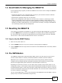
1.7 LEDs
Look at the LED lights on the front panel to determine the status of the NBG6716. Use the LED
button at the side panel of the device to turn the LED lights on or off. If you have already pushed
the LED button to the ON position but none of the LEDS are on, make sure the NBG6716 is
receiving power and the power is turned on.
Note: The Power LED will be on even if you push the LED button to the OFF position.
This is for you to determine whether the NBG6716 is powered on.
Figure 3 LED Button
LED button
18
NBG6716 User’s Guide
Chapter 1 Introduction
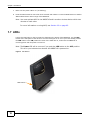
Figure 4 Front Panel
Power
Internet
WAN
WLAN 2.4G
WLAN 5G
WPS
Button
USB 1-2
LAN 1-4
WPS
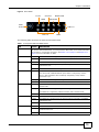
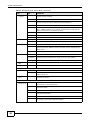
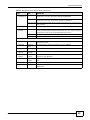
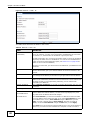
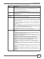
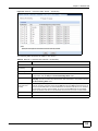
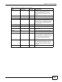
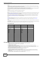
The following table describes the LEDs and the WPS button.
Table 1 Front panel LEDs and WPS button
LED
STATUS
WPS Button
Press this button for 1 second to set up a wireless connection via WiFi Protected Setup
with another WPS-enabled client. You must press the WPS button on the client side within
120 seconds for a successful connection. See Section 1.6 on page 17 and Chapter 9 on
page 57 for more information on WPS.
Power
WAN
Internet
DESCRIPTION
On
The NBG6716 is receiving power and functioning properly.
Off
The NBG6716 is not receiving power.
On
The NBG6716’s WAN connection is ready.
Blinking
The NBG6716 is sending/receiving data through the WAN with a 1000Mbps
transmission rate.
Off
The WAN connection is not ready, or has failed.
On
The NBG6716 has an IP connection but no traffic.
Your device has a WAN IP address (either static or assigned by a DHCP
server), PPP negotiation was successfully completed (if used) and the
connection is up.
WLAN 2.4/5G
Blinking
The NBG6716 is sending or receiving IP traffic.
Off
The NBG6716 does not have an IP connection.
On
The NBG6716 is ready, but is not sending/receiving data through the 5G
wireless LAN.
Blinking
The NBG6716 is sending/receiving data through the 5G wireless LAN.
The NBG6716 is negotiating a WPS connection with a wireless client.
LAN 1-4
USB 1-2
NBG6716 User’s Guide
Off
The wireless LAN is not ready or has failed.
On
The NBG6716’s LAN connection is ready.
Blinking
The NBG6716 is sending/receiving data through the LAN with a 1000Mbps
transmission rate.
Off
The LAN connection is not ready, or has failed.
On
The NBG6716 has a USB device installed.
Blinking
The NBG6716 is transmitting and/or receiving data from routers through an
installed USB device.
Off
There is no USB device connected to the NBG6716.
19
Chapter 1 Introduction
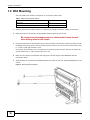
1.8 Wall Mounting
You may need screw anchors if mounting on a concrete or brick wall.
Table 2 Wall Mounting Information
Distance between holes
12.7 cm
M4 Screws
Two
Screw anchors (optional)
Two
1
Select a position free of obstructions on a wall strong enough to hold the weight of the device.
2
Mark two holes on the wall at the appropriate distance apart for the screws.
Be careful to avoid damaging pipes or cables located inside the wall
when drilling holes for the screws.
3
If using screw anchors, drill two holes for the screw anchors into the wall. Push the anchors into the
full depth of the holes, then insert the screws into the anchors. Do not insert the screws all the way
in - leave a small gap of about 0.5 cm.
If not using screw anchors, use a screwdriver to insert the screws into the wall. Do not insert the
screws all the way in - leave a gap of about 0.5 cm.
4
Make sure the screws are fastened well enough to hold the weight of the NBG6716 with the
connection cables.
5
Align the holes on the back of the NBG6716 with the screws on the wall. Hang the NBG6716 on the
screws.
Figure 5 Wall Mounting Example
20
NBG6716 User’s Guide
C HAPT ER
2
Connection Wizard
2.1 Overview
This chapter provides information on the wizard setup screens in the Web Configurator.
The Web Configurator’s wizard setup helps you configure your device to access the Internet. Refer
to your ISP for your Internet account information. Leave a field blank if you don’t have that
information.
2.2 Accessing the Wizard
Launch your web browser and type "http://192.168.1.1" as the website address. Type "1234"
(default) as the password and click Login.
Note: The Wizard appears when the NBG6716 is accessed for the first time or when you
reset the NBG6716 to its default factory settings.
If you have already configured the wizard screens and want to open it again, click
the eaZy123 icon on the network map screen in Easy Mode.
The Web Configurator is set to Easy Mode by default after login. If you are in
Expert Mode, you can click the Easy Mode icon on the upper right corner of any
Web Configurator screen to go to Easy Mode.
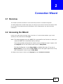
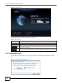
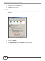
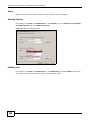
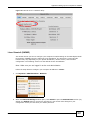
The Wizard screen opens. Choose your Language and click Connect to Internet.
NBG6716 User’s Guide
21
Chapter 2 Connection Wizard
Figure 6 Welcome
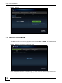
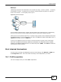
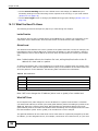
2.3 Connect to Internet
The NBG6716 offers two Internet connection types. They are IPoE or PPPoE. The wizard attempts
to detect which WAN connection type you are using.
Figure 7 Detecting your Internet Connection Type
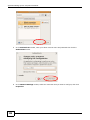
If the wizard does not detect a connection type, you must select one from the drop-down list box.
Check with your ISP to make sure you use the correct type.
22
NBG6716 User’s Guide
Chapter 2 Connection Wizard
Note: If you get an error message, check your hardware connections. Make sure your
Internet connection is up and running.
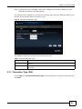
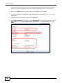
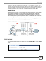
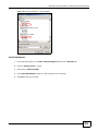
The following screen depends on your Internet connection type. Enter the details provided by your
Internet Service Provider (ISP) in the fields (if any).
Figure 8 Internet Connection Type
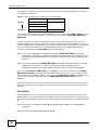
Your NBG6716 detects the following Internet Connection type.
Table 3 Internet Connection Type
CONNECTION TYPE
DESCRIPTION
IPoE
Select the IPoE (IP over Ethernet) option when the WAN port is used as a regular
Ethernet.
PPPoE
Select the PPPoE (Point-to-Point Protocol over Ethernet) option for a dial-up
connection.
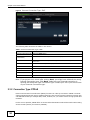
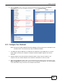
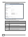
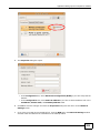
2.3.1 Connection Type: IPoE
Choose IPoE as the Internet Connection Type when the WAN port is used as a regular Ethernet.
Click Next.
NBG6716 User’s Guide
23
Chapter 2 Connection Wizard
Figure 9 Internet Connection Type: IPoE
The following table describes the labels in this screen.
Table 4 Internet Connection Type: IPoE
LABEL
DESCRIPTION
Internet Connection Type
Select the IPoE option.
Obtain an IP Address
Automatically
Select this radio button if your ISP did not assign you a fixed IP address.
Static IP Address
Select this radio button if your ISP assigned an IP address for your Internet
connection.
IP Address
Enter the IP address provided by your ISP.
Subnet Mask
Enter the IP subnet mask in this field.
Gateway IP Address
Enter the gateway IP address in this field.
Exit
Click this to close the wizard screen without saving.
Back
Click this to return to the previous screen.
Next
Click this to continue.
Note: If you get an error screen after clicking Next, you might have selected the wrong
Internet Connection type. Click Back, make sure your Internet connection is
working and select the right Connection Type. Contact your ISP if you are not sure
of your Internet Connection type.
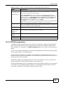
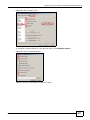
2.3.2 Connection Type: PPPoE
Point-to-Point Protocol over Ethernet (PPPoE) functions as a dial-up connection. PPPoE is an IETF
(Internet Engineering Task Force) standard specifying how a host personal computer interacts with
a broadband modem (for example DSL, cable, wireless, etc.) to achieve access to high-speed data
networks.
For the service provider, PPPoE offers an access and authentication method that works with existing
access control systems (for instance, RADIUS).
24
NBG6716 User’s Guide
Chapter 2 Connection Wizard
One of the benefits of PPPoE is the ability to let end users access one of multiple network services,
a function known as dynamic service selection. This enables the service provider to easily create
and offer new IP services for specific users.
Operationally, PPPoE saves significant effort for both the subscriber and the ISP/carrier, as it
requires no specific configuration of the broadband modem at the subscriber's site.
By implementing PPPoE directly on the NBG6716 (rather than individual computers), the computers
on the LAN do not need PPPoE software installed, since the NBG6716 does that part of the task.
Furthermore, with NAT, all of the LAN's computers will have Internet access.
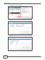
Figure 10 Internet Connection Type: PPPoE
The following table describes the labels in this screen.
Table 5 Internet Connection Type: PPPoE
LABEL
DESCRIPTION
Internet
Connection Type
Select the PPPoE option for a dial-up connection.
Get automatically
from ISP
Select this radio button if your ISP did not assign you a fixed IP address.
Use Fixed IP
Address
Select this radio button, provided by your ISP to give the NBG6716 a fixed, unique IP
address.
PPP Username
Type the user name given to you by your ISP.
PPP Password
Type the password associated with the user name above.
My WAN IP Address
Type the name of your service provider.
Exit
Click this to close the wizard screen without saving.
Back
Click this to return to the previous screen.
Next
Click this to continue.
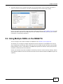
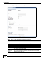
The NBG6716 connects to the Internet.
NBG6716 User’s Guide
25
Chapter 2 Connection Wizard
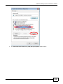
Figure 11 Connecting to the Internet
Note: If the Wizard successfully connects to the Internet, it proceeds to the next step. If
you get an error message, go back to the previous screen and make sure you have
entered the correct information provided by your ISP.
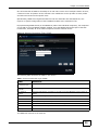
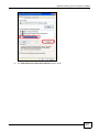
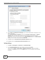
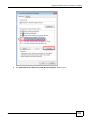
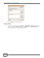
2.4 Router Password
Change the login password in the following screen. Enter the new password and retype it to
confirm. Click Next to proceed with the Wireless Security screen.
Figure 12 Router Password
26
NBG6716 User’s Guide
Chapter 2 Connection Wizard
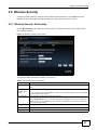
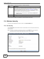
2.5 Wireless Security
Configure Wireless Settings. Configure the wireless network settings on your NBG6716 in the
following screen. The fields that show up depend on the kind of security you select.
2.5.1 Wireless Security: No Security
Choose No Security in the Wireless Security screen to let wireless devices within range access
your wireless network.
Figure 13 Wireless Security: No Security
The following table describes the labels in this screen.
Table 6 Wireless Security: No Security
LABEL
DESCRIPTION
Wireless Radio
Choose whether you want to apply the wireless security to 2.4G Hz or 5G Hz wireless
radio.
Wireless
Network Name
(SSID)
Enter a descriptive name (up to 32 printable 7-bit ASCII characters) for the wireless LAN.
Security Mode
If you change this field on the NBG6716, make sure all wireless stations use the same SSID
in order to access the network.
Select a security level from the drop-down list box.
Choose No Security to have no wireless LAN security configured. If you do not enable any
wireless security on your NBG6716, your network is accessible to any wireless networking
device that is within range.
Exit
Click this to close the wizard screen without saving.
Back
Click this to return to the previous screen.
Next
Click this to continue.
NBG6716 User’s Guide
27
Chapter 2 Connection Wizard
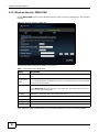
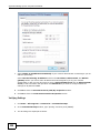
2.5.2 Wireless Security: WPA2-PSK
Choose WPA2-PSK security in the Wireless Security screen to set up a password for your wireless
network.
Figure 14 Wireless Security: WPA2-PSK
The following table describes the labels in this screen.
Table 7 Wireless Security: WPA2-PSK
LABEL
DESCRIPTION
Wireless Radio
Choose whether you want to apply the wireless security to 2.4G Hz or 5G Hz wireless
radio.
Wireless
Network Name
(SSID)
Enter a descriptive name (up to 32 printable 7-bit ASCII characters) for the wireless LAN.
Security Mode
If you change this field on the NBG6716, make sure all wireless stations use the same SSID
in order to access the network.
Select a security level from the drop-down list box.
Choose WPA2-PSK security to configure a Pre-Shared Key. Choose this option only if your
wireless clients support WPA2-PSK.
Wireless
password
Type from 8 to 63 case-sensitive ASCII characters. You can set up the most secure wireless
connection by configuring WPA in the wireless LAN screens.
Verify Password
Retype the password to confirm.
Exit
Click this to close the wizard screen without saving.
Back
Click this to return to the previous screen.
Next
Click this to continue.
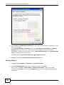
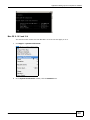
Congratulations! Open a web browser, such as Internet Explorer, to visit your favorite website.
28
NBG6716 User’s Guide
Chapter 2 Connection Wizard
Note: If you cannot access the Internet when your computer is connected to one of the
NBG6716’s LAN ports, check your connections. Then turn the NBG6716 off, wait for
a few seconds then turn it back on. If that does not work, log in to the web
configurator again and check you have typed all information correctly. See the
User’s Guide for more suggestions.
Figure 15 Congratulations
You can also click GO to open the Easy Mode Web Configurator of your NBG6716.
You have successfully set up your NBG6716 to operate on your network and access the Internet.
You are now ready to connect wirelessly to your NBG6716 and access the Internet.
NBG6716 User’s Guide
29
Chapter 2 Connection Wizard
30
NBG6716 User’s Guide
C HAPT ER
3
Introducing the Web Configurator
3.1 Overview
This chapter describes how to access the NBG6716 Web Configurator and provides an overview of
its screens.
The Web Configurator is an HTML-based management interface that allows easy setup and
management of the NBG6716 via Internet browser. Use Internet Explorer 8.0 and later versions,
Mozilla Firefox 21 and later versions, Safari 6.0 and later versions or Google Chrome 26.0 and later
versions. The recommended screen resolution is 1024 by 768 pixels.
In order to use the Web Configurator you need to allow:
• Web browser pop-up windows from your device. Web pop-up blocking is enabled by default in
Windows XP SP (Service Pack) 2.
• JavaScript (enabled by default).
• Java permissions (enabled by default).
Refer to the Troubleshooting chapter (Chapter 24 on page 191) to see how to make sure these
functions are allowed in Internet Explorer.
3.2 Accessing the Web Configurator
1
Make sure your NBG6716 hardware is properly connected and prepare your computer or computer
network to connect to the NBG6716 (refer to the Quick Start Guide).
2
Launch your web browser.
3
The NBG6716 is in router mode by default. Type "http://192.168.1.1" as the website address.
If the NBG6716 is in access point, the IP address is 192.168.1.2. See Chapter 4 on page 35 for
more information about the modes of the NBG6716.
Your computer must be in the same subnet in order to access this website address.
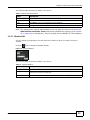
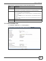
3.2.1 Login Screen
Note: If this is the first time you are accessing the Web Configurator, you may be
redirected to the Wizard. Refer to Chapter 2 on page 21 for the Connection Wizard
screens.
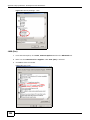
The Web Configurator initially displays the following login screen.
NBG6716 User’s Guide
31
Chapter 3 Introducing the Web Configurator
Figure 16 Login screen
The following table describes the labels in this screen.
Table 8 Login screen
LABEL
DESCRIPTION
Language
Select the language you want to use to configure the Web Configurator.
Password
Type "1234" (default) as the password. Click Login.
This shows the current weather, either in celsius or fahrenheit, of the city you specify in
Section 3.2.2.1 on page 33.
This shows the time (hh:mm:ss) and date (yyyy:mm:dd) of the timezone you select in
Section 23.5 on page 183. The time is in 24-hour format, for example 15:00 is 3:00 PM.
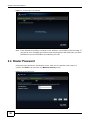
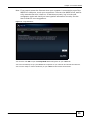
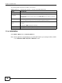
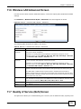
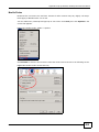
3.2.2 Password Screen
You should see a screen asking you to change your password (highly recommended) as shown
next.
Figure 17 Change Password Screen
32
NBG6716 User’s Guide
Chapter 3 Introducing the Web Configurator
The following table describes the labels in this screen.
Table 9 Change Password Screen
LABEL
DESCRIPTION
New Password
Type a new password.
Retype to Confirm
Retype the password for confirmation.
Apply
Click Apply to save your changes back to the NBG6716.
Ignore
Click Ignore if you do not want to change the password this time.
Note: The management session automatically times out when the time period set in the
Administrator Inactivity Timer field expires (default five minutes; go to Chapter
23 on page 181 to change this). Simply log back into the NBG6716 if this happens.
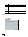
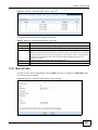
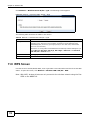
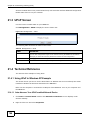
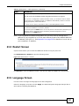
3.2.2.1 Weather Edit
You can change the temperature unit and select the location for which you want to know the
weather.
Click the
icon to change the Weather display.
Figure 18 Change Weather
The following table describes the labels in this screen.
Table 10 Change Weather
LABEL
DESCRIPTION
Change Unit
Choose which temperature unit you want the NBG6716 to display.
Change Location
Select the location for which you want to know the weather. If the city you want is not
listed, choose one that is closest to it.
Finish
Click this to apply the settings and refresh the date and time display.
NBG6716 User’s Guide
33
Chapter 3 Introducing the Web Configurator
34
NBG6716 User’s Guide
C HAPT ER
4
NBG6716 Modes
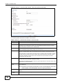
4.1 Overview
This chapter introduces the different modes available on your NBG6716. First, the term “mode”
refers to two things in this User’s Guide.
• Web Configurator mode. This refers to the Web Configurator interface you want to use for
editing NBG6716 features.
• Device mode. This is the operating mode of your NBG6716, or simply how the NBG6716 is
being used in the network.
4.1.1 Web Configurator Modes
This refers to the configuration interface of the Web Configurator, which has two modes:
• Easy Mode: The Web Configurator shows this mode by default. Refer to Chapter 5 on page 37
for more information on the screens in this mode. This interface may be sufficient for users who
just want to use the device.
• Expert Mode: Advanced users can change to this mode to customize all the functions of the
NBG6716. Click Expert Mode after logging into the Web Configurator. The User’s Guide Chapter
3 on page 31 through Chapter 23 on page 189 discusses the screens in this mode.
4.1.2 Device Modes
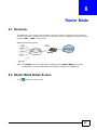
This refers to the operating mode of the NBG6716, which can act as a:
• Router: This is the default device mode of the NBG6716. Use this mode to connect the local
network to another network, like the Internet. Go to Section 6.2 on page 49 to view the Status
screen in this mode.
• Access Point: Use this mode if you want to extend your network by allowing network devices to
connect to the NBG6716 wirelessly. Go to Section 7.4 on page 59 to view the Status screen in
this mode.
For more information on these modes and to change the mode of your NBG6716, refer to Chapter
23 on page 189.
The menu for changing device modes is available in Expert Mode only.
Note: Choose your device mode carefully to avoid having to change it later.
When changing to another mode, the IP address of the NBG6716 changes. The running applications
and services of the network devices connected to the NBG6716 can be interrupted.
NBG6716 User’s Guide
35
Chapter 4 NBG6716 Modes
36
NBG6716 User’s Guide
C HAPT ER
5
Easy Mode
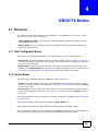
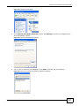
5.1 Overview
The Web Configurator is set to Easy Mode by default. You can configure several key features of the
NBG6716 in this mode. This mode is useful to users who are not fully familiar with some features
that are usually intended for network administrators.
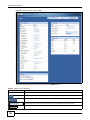
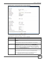
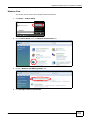
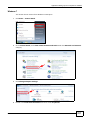
When you log in to the Web Configurator, the following screen opens.
Figure 19 Easy Mode: Network Map
Navigation Panel
Network Map
Go to
Status
Screen
Control Panel
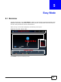
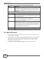
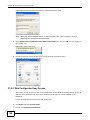
Click Status to open the following screen.
NBG6716 User’s Guide
37
Chapter 5 Easy Mode
Figure 20 Easy Mode: Status Screen
Navigation Panel
Go to
Network
Map
Screen
Status Screen
Control Panel
5.2 What You Can Do
You can do the following in this mode:
• Use the Navigation Panel to opt out of the Easy Mode (Section 5.4 on page 39).
• Use the Network Map screen to check whether your NBG6716 is connected to the Internet or
any networking devices and view the transmission speed between them (Section 5.5 on page
39).
• Use the Control Panel to configure and enable NBG6716 features, including wireless scheduling,
wireless security, content filtering, firewall and so on (Section 5.6 on page 40).
• Use the Status Screen to view read-only information about the NBG6716, including the WAN IP,
MAC address of the NBG6716, the firmware version and wireless settigns (Section 5.7 on page
46).
5.3 What You Need to Know
Between the different device modes, the Control Panel (Section 5.6 on page 40) changes
depending on which features are applicable to the mode:
• Router Mode: All Control Panel features are available.
• Access Point Mode: Only Power Saving and Wireless Security are available.
38
NBG6716 User’s Guide
Chapter 5 Easy Mode
5.4 Navigation Panel
Use this navigation panel to opt out of the Easy Mode.
Figure 21 Control Panel
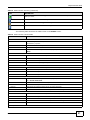
The following table describes the labels in this screen.
Table 11 Control Panel
ITEM
DESCRIPTION
Expert Mode
Click this to change to Expert Mode and customize features of the NBG6716.
eaZy123
Click this icon to open the setup wizard.
Logout
Click this to end the Web Configurator session and go to the Login page.
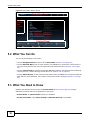
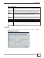
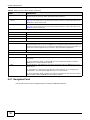
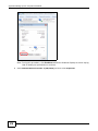
5.5 Network Map
When you log into the Web Configurator, the Network Map is shown as follows.
Figure 22 Network Map
You can view the upstream and downstream transmission speed between the NBG6716 and the
Internet and/or between the NBG6716 and the connected device(s) (represented by icons
indicating the kind of network device), including those connecting wirelessly.
NBG6716 User’s Guide
39
Chapter 5 Easy Mode
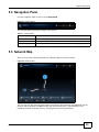
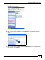
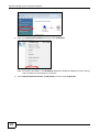
5.6 Control Panel
The features configurable in Easy Mode are shown in the Control Panel.
Figure 23 Control Panel
Switch ON to enable the feature. Otherwise, switch OFF. If the feature is turned on, the green light
flashes. If it is turned off, the red light flashes.
Additionally, click the feature to open a screen where you can edit its settings.
The following table describes the labels in this screen.
Table 12 Control Panel
ITEM
DESCRIPTION
Power Saving
Click this to schedule the wireless feature of the NBG6716.
Disabling the wireless function helps lower the energy consumption of the
NBG6716.
Switch ON to apply wireless scheduling. Otherwise, switch OFF.
Refer to Section 5.6.1 on page 40 to see this screen.
Content Filter
Click this to restrict access to certain websites, based on keywords contained in
URLs, to which you do not want users in your network to open.
Switch ON to apply website filtering. Otherwise, switch OFF.
Refer to Section 5.6.2 on page 41 to see this screen.
Firewall
Switch ON to ensure that your network is protected from Denial of Service (DoS)
attacks. Otherwise, switch OFF.
Refer to Section 5.6.3 on page 42 to see this screen.
Internet Setting
Click this to configure the Internet connection settings.
Refer to Section 5.6.4 on page 42 to see this screen.
Wireless Security
Click this to configure the wireless security, such as SSID, security mode and WPS
key on your NBG6716.
Refer to Section 5.6.5 on page 44 to see this screen.
5.6.1 Power Saving
Use this screen to set the day of the week and time of the day when your wireless LAN is turned on
and off. Wireless LAN scheduling is disabled by default.
Disabling the wireless capability lowers the energy consumption of the of the NBG6716.
40
NBG6716 User’s Guide
Chapter 5 Easy Mode
Figure 24 Power Saving
The following table describes the labels in this screen.
Table 13 Power Saving
LABEL
DESCRIPTION
Wireless Radio
Choose whether you want to apply the power saving schedule to 2.4G Hz or 5G Hz
wireless radio.
WLAN Status
Select On or Off to specify whether the Wireless LAN is turned on or off (depending on
what you selected in the WLAN Status field). This field works in conjunction with the
Day and For the following times fields.
Day
Select Everyday or the specific days to turn the Wireless LAN on or off.
If you select Everyday you can not select any specific days. This field works in
conjunction with the For the following times field.
For the following
times (24-Hour
Format)
Select a begin time using the first set of hour and minute (min) drop down boxes and
select an end time using the second set of hour and minute (min) drop down boxes. If
you have chosen On earlier for the WLAN Status the Wireless LAN will turn on between
the two times you enter in these fields. If you have chosen Off earlier for the WLAN
Status the Wireless LAN will turn off between the two times you enter in these fields.
In this time format, midnight is 00:00 and progresses up to 24:00. For example, 6:00
PM is 18:00.
Apply
Click Apply to save your changes back to the NBG6716.
Cancel
Click Cancel to close this screen without saving any changes.
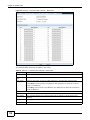
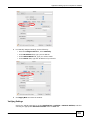
5.6.2 Content Filter
Use this screen to restrict access to certain websites, based on keywords contained in URLs, to
which you do not want users in your network to open.
NBG6716 User’s Guide
41
Chapter 5 Easy Mode
Figure 25 Content Filter
The following table describes the labels in this screen.
Table 14 Content Filter
LABEL
DESCRIPTION
Add
Click Add after you have typed a keyword.
Repeat this procedure to add other keywords. Up to 64 keywords are allowed.
Note: The NBG6716 does not recognize wildcard characters as keywords.
When you try to access a web page containing a keyword, you will get a message telling
you that the content filter is blocking this request.
Delete
Highlight a keyword in the text box and click Delete to remove it. The keyword
disappears from the text box after you click Apply.
Apply
Click Apply to save your changes.
Cancel
Click Cancel to close this screen without saving any changes.
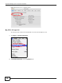
5.6.3 Firewall
Enable this feature to protect the network from Denial of Service (DoS) attacks. The NBG6716
blocks repetitive pings from the WAN that can otherwise cause systems to slow down or hang.
Figure 26 Firewall
Click OK to close this screen.
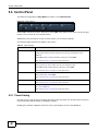
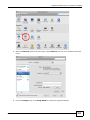
5.6.4 Internet Setting
Use this screen to configure your NBG6716 for Internet access. You should already have Internet
account information from your ISP. The screen varies depending on the Internet connection type
you selected.
42
NBG6716 User’s Guide
Chapter 5 Easy Mode
Figure 27 Internet Setting (IPoE)
Figure 28 Internet Setting (PPPoE)
The following table describes the labels in this screen.
Table 15 Internet Setting
LABEL
DESCRIPTION
Internet
Connection Type
Select the IPoE (IP over Ethernet) option when the WAN port is used as a regular
Ethernet.
Select the PPPoE (Point-to-Point Protocol over Ethernet) option for a dial-up connection.
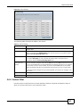
The following fields are available if you select IPoE.
Obtain an IP
Address
Automatically
Select this radio button if your ISP did not assign you a fixed IP address.
Static IP Address Select this radio button if your ISP assigned an IP address for your Internet connection.
IP Address
NBG6716 User’s Guide
Enter the IP address provided by your ISP.
43
Chapter 5 Easy Mode
Table 15 Internet Setting (continued)
LABEL
DESCRIPTION
Subnet Mask
Enter the IP subnet mask in this field.
Gateway IP
Address
Enter the gateway IP address in this field.
The following fields are available if you select PPPoE.
Get
automatically
from ISP
Select this radio button if your ISP did not assign you a fixed IP address.
Use Fixed IP
Address
Select this radio button, provided by your ISP to give the NBG6716 a fixed, unique IP
address.
PPP Username
Type the user name given to you by your ISP.
PPP Password
Type the password associated with the user name above.
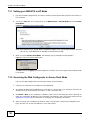
My WAN IP
Address
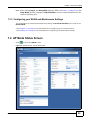
Type the name of your service provider.
Cancel
Click Cancel to close this screen.
Apply
Click Apply to save your changes back to the NBG6716.
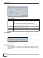
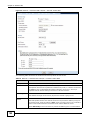
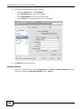
5.6.5 Wireless Security
Use this screen to configure security for your the wireless LAN. You can enter the SSID and select
the wireless security mode in the following screen.
Note: You can enable the wireless function of your NBG6716 by first turning on the switch
in the back panel.
Figure 29 Wireless Security
44
NBG6716 User’s Guide
Chapter 5 Easy Mode
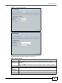
The following table describes the general wireless LAN labels in this screen.
Table 16 Wireless Security
LABEL
DESCRIPTION
Wireless Radio
Choose whether you want to apply the wireless security to 2.4G Hz or 5G Hz wireless
radio.
Wireless
Network Name
(SSID)
(Service Set IDentity) The SSID identifies the Service Set with which a wireless station is
associated. Wireless stations associating to the access point (AP) must have the same
SSID. Enter a descriptive name (up to 32 keyboard characters) for the wireless LAN.
Security mode
Select WPA2-PSK to add security on this wireless network. The wireless clients which
want to associate to this network must have same wireless security settings as this device.
After you select to use a security, additional options appears in this screen.
Select No Security to allow any client to connect to this network without authentication.
Wireless
password
This field appears when you choose wither WPA2-PSK as the security mode.
Verify password
Type the password again to confirm.
Apply
Click Apply to save your changes back to the NBG6716.
Cancel
Click Cancel to close this screen.
WPS
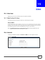
Click this to configure the WPS screen.
Type a pre-shared key from 8 to 63 case-sensitive keyboard characters.
You can transfer the wireless settings configured here (Wireless Security screen) to
another wireless device that supports WPS.
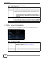
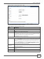
5.6.6 WPS
Use this screen to add a wireless station to the network using WPS. Click WPS in the Wireless
Security to open the following screen.
Figure 30 Wireless Security: WPS
NBG6716 User’s Guide
45
Chapter 5 Easy Mode
The following table describes the labels in this screen.
Table 17 Wireless Security: WPS
LABEL
DESCRIPTION
Wireless Security
Click this to go back to the Wireless Security screen.
WPS
Create a secure wireless network simply by pressing a button.
The NBG6716 scans for a WPS-enabled device within the range and performs wireless
security information synchronization.
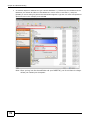
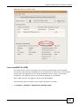
Note: After you click the WPS button on this screen, you have to press a similar button in
the wireless station utility within 2 minutes. To add the second wireless station, you
have to press these buttons on both device and the wireless station again after the
first 2 minutes.
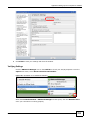
Register
Create a secure wireless network simply by entering a wireless client's PIN (Personal
Identification Number) in the NBG6716’s interface and pushing this button.
Type the same PIN number generated in the wireless station’s utility. Then click Register
to associate to each other and perform the wireless security information synchronization.
Exit
Click Exit to close this screen.
5.7 Status Screen in Easy Mode
In the Network Map screen, click Status to view read-only information about the NBG6716.
Figure 31 Status Screen in Easy Mode
The following table describes the labels in this screen.
Table 18 Status Screen in Easy Mode
ITEM
DESCRIPTION
Name
This is the name of the NBG6716 in the network. You can change this in the
Maintenance > General screen in Section 23.3 on page 181.
Time
This is the current system date and time.
The date is in YYYY:MM:DD (Year-Month-Day) format. The time is in HH:MM:SS
(Hour:Minutes:Seconds) format.
46
WAN IP
This is the IP address of the WAN port.
MAC Address
This is the MAC address of the NBG6716.
NBG6716 User’s Guide
Chapter 5 Easy Mode
Table 18 Status Screen in Easy Mode (continued)
ITEM
DESCRIPTION
Firmware Version
This shows the firmware version of the NBG6716.
The firmware version format shows the trunk version, model code and release
number.
Wireless 2.4G Network
Name (SSID)
This shows the SSID of the wireless network. You can configure this in the Wireless
Security screen (Section 5.6.5 on page 44; Section 11.2 on page 98).
Wireless 5G Network
Name (SSID)
Security
NBG6716 User’s Guide
This shows the wireless security used by the NBG6716.
47
Chapter 5 Easy Mode
48
NBG6716 User’s Guide
C HAPT ER
6
Router Mode
6.1 Overview
The NBG6716 is set to router mode by default. Routers are used to connect the local network to
another network (for example, the Internet). In the figure below, the NBG6716 connects the local
network (LAN1 ~ LAN4) to the Internet.
Figure 32 NBG6716 Network
Modem
Note: The Status screen is shown after changing to the Expert Mode of the Web
Configurator. It varies depending on the device mode of your NBG6716.
6.2 Router Mode Status Screen
Click
NBG6716 User’s Guide
to open the status screen.
49
Chapter 6 Router Mode
Figure 33 Status Screen: Router Mode
The following table describes the icons shown in the Status screen.
Table 19 Status Screen Icon Key
ICON
DESCRIPTION
Logout
Click this at any time to exit the Web Configurator.
Click this icon to view copyright and a link for related product information.
Click this icon to go to Easy Mode. See Chapter 5 on page 37.
Select a number of seconds or None from the drop-down list box to refresh all screen statistics
automatically at the end of every time interval or to not refresh the screen statistics.
Click this button to refresh the status screen statistics.
50
NBG6716 User’s Guide
Chapter 6 Router Mode
Table 19 Status Screen Icon Key (continued)
ICON
DESCRIPTION
Click this icon to see the Status page. The information in this screen depends on the device
mode you select.
Click this icon to see the Monitor navigation menu.
Click this icon to see the Configuration navigation menu.
Click this icon to see the Maintenance navigation menu.
The following table describes the labels shown in the Status screen.
Table 20 Status Screen: Router Mode
LABEL
DESCRIPTION
Device Information
Host Name
This is the System Name you enter in the Maintenance > General screen. It is for
identification purposes.
Model Number
This is the model name of your device.
Firmware Version
This is the firmware version and the date created.
Sys OP Mode
This is the device mode (Section 4.1.2 on page 35) to which the NBG6716 is set - Router
Mode.
WAN Information
MAC Address
This shows the WAN Ethernet adapter MAC Address of your device.
IP Address
This shows the WAN port’s IP address.
IP Subnet Mask
This shows the WAN port’s subnet mask.
Default Gateway
This shows the WAN port’s gateway IP address.
LAN Information
MAC Address
This shows the LAN Ethernet adapter MAC Address of your device.
IP Address
This shows the LAN port’s IP address.
IP Subnet Mask
This shows the LAN port’s subnet mask.
DHCP
This shows the LAN port’s DHCP role - Server or Disable.
WLAN 2.4G Information
WLAN OP Mode
This is the device mode (Section 4.1.2 on page 35) to which the NBG6716’s wireless LAN is
set - Access Point Mode.
MAC Address
This shows the 2.4GHz wireless adapter MAC Address of your device.
SSID
This shows a descriptive name used to identify the NBG6716 in the 2.4GHz wireless LAN.
Channel
This shows the channel number which you select manually.
Security
This shows the level of wireless security the NBG6716 is using.
WLAN 5G Information
MAC Address
This shows the 5GHz wireless adapter MAC Address of your device.
SSID
This shows a descriptive name used to identify the NBG6716 in the 5GHz wireless LAN.
Channel
This shows the channel number which you select manually.
Security
This shows the level of wireless security the NBG6716 is using.
Firewall
This shows whether the firewall is enabled or not.
Summary
NBG6716 User’s Guide
51
Chapter 6 Router Mode
Table 20 Status Screen: Router Mode (continued)
LABEL
DESCRIPTION
Packet Statistics
Click Details... to go to the Monitor > Packet Statistics screen (Section 9.5 on page 81).
Use this screen to view port status and packet specific statistics.
WLAN 2.4G Station
Status
Click Details... to go to the Monitor > WLAN 2.4G Station Status screen (Section 9.6 on
page 82). Use this screen to view the wireless stations that are currently associated to the
NBG6716’s 2.4GHz wireless LAN.
WLAN 5G Station Status
Click Details... to go to the Monitor > WLAN 5G Station Status screen (Section 9.6 on
page 82). Use this screen to view the wireless stations that are currently associated to the
NBG6716’s 5GHz wireless LAN.
System Status
Item
This column shows the type of data the NBG6716 is recording.
Data
This column shows the actual data recorded by the NBG6716.
System Up Time
This is the total time the NBG6716 has been on.
Current Date/Time
This field displays your NBG6716’s present date and time.
System Resource
- CPU Usage
This displays what percentage of the NBG6716’s processing ability is currently used. When
this percentage is close to 100%, the NBG6716 is running at full load, and the throughput is
not going to improve anymore. If you want some applications to have more throughput, you
should turn off other applications (for example, using bandwidth management.)
- Memory Usage
This shows what percentage of the heap memory the NBG6716 is using.
Interface Status
Interface
This displays the NBG6716 port types. The port types are: WAN, LAN and WLAN.
Status
For the LAN and WAN ports, this field displays Down (line is down) or Up (line is up or
connected).
For the 2.4GHz/5GHz WLAN, it displays Up when the 2.4GHz/5GHz WLAN is enabled or
Down when the 2.4G/5G WLAN is disabled.
Rate
For the LAN ports, this displays the port speed and duplex setting or N/A when the line is
disconnected.
For the WAN port, it displays the port speed and duplex setting if you’re using Ethernet
encapsulation. This field displays N/A when the line is disconnected.
For the 2.4GHz/5GHz WLAN, it displays the maximum transmission rate when the 2.4GHz/
5GHz WLAN is enabled and N/A when the WLAN is disabled.
6.2.1 Navigation Panel
Use the sub-menus on the navigation panel to configure NBG6716 features.
52
NBG6716 User’s Guide
Chapter 6 Router Mode
Figure 34 Navigation Panel: Router Mode
The following table describes the sub-menus.
Table 21 Navigation Panel: Router Mode
LINK
TAB
Status
FUNCTION
This screen shows the NBG6716’s general device, system and interface
status information. Use this screen to access summary statistics tables.
MONITOR
Log
View Log
Use this screen to view the list of activities recorded by your NBG6716.
Log Setting
Use this screen to select the logs you wish to display.
DHCP Table
Use this screen to view current DHCP client information.
Packet Statistics
Use this screen to view port status and packet specific statistics.
WLAN 2.4G
Station Status
Use this screen to view the wireless stations that are currently associated
to the NBG6716’s 2.4GHz wireless LAN.
WLAN 5G
Station Status
Use this screen to view the wireless stations that are currently associated
to the NBG6716’s 5GHz wireless LAN.
CONFIGURATION
Network
WAN
NBG6716 User’s Guide
Internet
Connection
This screen allows you to configure ISP parameters, WAN IP address
assignment, DNS servers and the WAN MAC address.
Advanced
Use this screen to configure other advanced properties.
53
Chapter 6 Router Mode
Table 21 Navigation Panel: Router Mode (continued)
LINK
TAB
FUNCTION
General
Use this screen to enable the wireless LAN and configure wireless LAN and
wireless security settings.
More AP
Use this screen to configure multiple BSSs on the NBG6716.
MAC Filter
Use the MAC filter screen to configure the NBG6716 to block access to
devices or block the devices from accessing the NBG6716.
Advanced
This screen allows you to configure advanced wireless settings.
QoS
Use this screen to configure Wi-Fi Multimedia Quality of Service (WMM
QoS). WMM QoS allows you to prioritize wireless traffic according to the
delivery requirements of individual services.
WPS
Use this screen to configure WPS.
WPS Station
Use this screen to add a wireless station using WPS.
Scheduling
Use this screen to schedule the times the Wireless LAN is enabled.
IP
Use this screen to configure LAN IP address and subnet mask.
IP Alias
Use this screen to have the NBG6716 apply IP alias to create LAN subnets.
General
Use this screen to enable the NBG6716’s DHCP server.
Advanced
Use this screen to assign IP addresses to specific individual computers
based on their MAC addresses and to have DNS servers assigned by the
DHCP server.
Client List
Use this screen to view information related to your DHCP status.
General
Use this screen to enable NAT.
Port
Forwarding
Use this screen to configure servers behind the NBG6716 and forward
incoming service requests to the server(s) on your local network.
Port Trigger
Use this screen to change your NBG6716’s port triggering settings.
Dynamic
DNS
Dynamic DNS
Use this screen to set up dynamic DNS.
Static Route
Static Route
Use this screen to configure IP static routes.
General
Use this screen to activate/deactivate the firewall.
Services
This screen shows a summary of the firewall rules, and allows you to edit/
add a firewall rule.
Content Filter
Use this screen to block certain web features and sites containing certain
keywords in the URL.
Network
Use this screen to view transmission data rates between the NBG6716 and
the Internet or conencted devices.
Bandwidth
Use this screen to configure the maximum allowable bandwidth and enable
automatic update.
Priorities
Use this screen to change the priority of the conencted devices.
Up Time
Use this screen to view the top five traffic flows transmitting from/to the
selected LAN device(s).
Downloads
Use this screen to view the type and percentage of most download traffic.
All Events
Use this screen to view the time at which a traffic flow is given bandwidth
for optimal, good or best-effort performance.
Wireless LAN
2.4G/5G
LAN
DHCP Server
NAT
Security
Firewall
Content
Filter
Management
Streamboost
Management
54
NBG6716 User’s Guide
Chapter 6 Router Mode
Table 21 Navigation Panel: Router Mode (continued)
LINK
TAB
FUNCTION
WWW
Use this screen to configure through which interface(s) and from which IP
address(es) users can use HTTP to manage the NBG6716.
Telnet
Use this screen to configure through which interface(s) and from which IP
address(es) users can use Telnet to manage the NBG6716.
Wake On LAN
Use this screen to enable Wake on LAN to remotely turn on a device on the
local network.
UPnP
General
Use this screen to enable UPnP on the NBG6716.
USB Media
Sharing
DLNA
Use this screen to have the NBG6716 function as a DLNA-compliant media
server, that lets DLNA-compliant media clients play video, audio, and photo
content files stored on the connected USB storage device.
SAMBA
Use this screen to enable file sharing through the NBG6716.
FTP
Use this screen to have the NBG6716 act as a FTP server.
General
General
Use this screen to view and change administrative settings such as system
and domain names.
Password
Password
Setup
Use this screen to change the password of your NBG6716.
Time
Time Setting
Use this screen to change your NBG6716’s time and date.
Firmware
Upgrade
Firmware
Upgrade
Use this screen to upload firmware to your NBG6716.
Backup/
Restore
Backup/
Restore
Use this screen to backup and restore the configuration or reset the factory
defaults to your NBG6716.
Restart
System
Restart
This screen allows you to reboot the NBG6716 without turning the power
off.
Language
Language
This screen allows you to select the language you prefer.
Sys OP Mode
Sys OP Mode
This screen allows you to select whether your device acts as a router, or an
access point.
Remote
Management
MAINTENANCE
NBG6716 User’s Guide
55
Chapter 6 Router Mode
56
NBG6716 User’s Guide
C HAPT ER
7
Access Point Mode
7.1 Overview
Use your NBG6716 as an access point (AP) if you already have a router or gateway on your
network. In this mode your NBG6716 bridges a wired network (LAN) and wireless LAN (WLAN) in
the same subnet. See the figure below for an example.
Figure 35 Wireless Internet Access in Access Point Mode
Many screens that are available in Router Mode are not available in Access Point Mode, such as
NAT and firewall.
Note: See Chapter 8 on page 65 for an example of setting up a wireless network in
Access Point mode.
7.2 What You Can Do
• Use the Status screen to view read-only information about your NBG6716 (Section 7.4 on page
59).
• Use the LAN screen to set the IP address for your NBG6716 acting as an access point (Section
7.5 on page 61).
7.3 What You Need to Know
See Chapter 8 on page 65 for a tutorial on setting up a network with the NBG6716 as an access
point.
NBG6716 User’s Guide
57
Chapter 7 Access Point Mode
7.3.1 Setting your NBG6716 to AP Mode
1
Log into the Web Configurator if you haven’t already. See the Quick start Guide for instructions on
how to do this.
2
To use your NBG6716 as an access point, go to Maintenance > Sys OP Mode and select Access
Point Mode.
Figure 36 Changing to Access Point mode
Note: You have to log in to the Web Configurator again when you change modes. As soon
as you do, your NBG6716 is already in Access Point mode.
3
When you select Access Point Mode, the following pop-up message window appears.
Figure 37 Pop up for Access Point mode
Click OK. Then click Apply. The Web Configurator refreshes once the change to Access Point mode
is successful.
7.3.2 Accessing the Web Configurator in Access Point Mode
Log in to the Web Configurator in Access Point mode, do the following:
58
1
Connect your computer to the LAN port of the NBG6716.
2
The default IP address of the NBG6716 is “192.168.1.2”. In this case, your computer must have an
IP address in the range between “192.168.1.3” and “192.168.1.254”.
3
Click Start > Run on your computer in Windows. Type “cmd” in the dialog box. Enter “ipconfig” to
show your computer’s IP address. If your computer’s IP address is not in the correct range then see
Appendix B on page 209 for information on changing your computer’s IP address.
4
After you’ve set your computer’s IP address, open a web browser such as Internet Explorer and
type “192.168.1.2” as the web address in your web browser.
NBG6716 User’s Guide
Chapter 7 Access Point Mode
Note: After clicking Login, the Easy Mode appears. Refer to Section on page 37 for the
Easy Mode screens. Change to Expert Mode to see the screens described in the
sections following this.
7.3.3 Configuring your WLAN and Maintenance Settings
The configuration of wireless and maintenance settings in Access Point Mode is the same as for
Router Mode.
• See Chapter 11 on page 93 for information on the configuring your wireless network.
• See Chapter 23 on page 181 for information on configuring your Maintenance settings.
7.4 AP Mode Status Screen
Click
to open the Status screen.
Figure 38 Status Screen: Access Point Mode
NBG6716 User’s Guide
59
Chapter 7 Access Point Mode
The following table describes the labels shown in the Status screen.
Table 22 Status Screen: Access Point Mode
LABEL
DESCRIPTION
Device Information
Host Name
This is the System Name you enter in the Maintenance > General screen. It is for
identification purposes.
Model Number
This is the model name of your device.
Firmware Version
This is the firmware version and the date created.
Sys OP Mode
This is the device mode (Section 4.1.2 on page 35) to which the NBG6716 is set - AP Mode.
LAN Information
MAC Address
This shows the LAN Ethernet adapter MAC Address of your device.
IP Address
This shows the LAN port’s IP address.
IP Subnet Mask
This shows the LAN port’s subnet mask.
DHCP
This shows the LAN port’s DHCP role - Client or None.
WLAN 2.4G Information
WLAN OP Mode
This is the device mode (Section 4.1.2 on page 35) to which the NBG6716’s wireless LAN is
set - Access Point Mode.
MAC Address
This shows the 2.4GHz wireless adapter MAC Address of your device.
SSID
This shows a descriptive name used to identify the NBG6716 in the 2.4GHz wireless LAN.
Channel
This shows the channel number which you select manually.
Security
This shows the level of wireless security the NBG6716 is using.
WLAN 5G Information
MAC Address
This shows the 5GHz wireless adapter MAC Address of your device.
SSID
This shows a descriptive name used to identify the NBG6716 in the 5GHz wireless LAN.
Channel
This shows the channel number which you select manually.
Security
This shows the level of wireless security the NBG6716 is using.
Summary
Packet Statistics
Click Details... to go to the Monitor > Packet Statistics screen (Section 9.5 on page 81).
Use this screen to view port status and packet specific statistics.
WLAN 2.4G Station
Status
Click Details... to go to the Monitor > WLAN 2.4G Station Status screen (Section 9.6 on
page 82). Use this screen to view the wireless stations that are currently associated to the
NBG6716’s 2.4GHz wireless LAN.
WLAN 5G Station Status
Click Details... to go to the Monitor > WLAN 5G Station Status screen (Section 9.6 on
page 82). Use this screen to view the wireless stations that are currently associated to the
NBG6716’s 5GHz wireless LAN.
System Status
Item
This column shows the type of data the NBG6716 is recording.
Data
This column shows the actual data recorded by the NBG6716.
System Up Time
This is the total time the NBG6716 has been on.
Current Date/Time
This field displays your NBG6716’s present date and time.
System Resource
- CPU Usage
This displays what percentage of the NBG6716’s processing ability is currently used. When
this percentage is close to 100%, the NBG6716 is running at full load, and the throughput is
not going to improve anymore. If you want some applications to have more throughput, you
should turn off other applications (for example, using bandwidth management.)
- Memory Usage
This shows what percentage of the heap memory the NBG6716 is using.
60
NBG6716 User’s Guide
Chapter 7 Access Point Mode
Table 22 Status Screen: Access Point Mode (continued)
LABEL
DESCRIPTION
Interface Status
Interface
This displays the NBG6716 port types. The port types are: LAN and WLAN.
Status
For the LAN ports, this field displays Down (line is down) or Up (line is up or connected).
For the 2.4GHz/5GHz WLAN, it displays Up when the 2.4GHz/5GHz WLAN is enabled or
Down when the 2.4G/5G WLAN is disabled.
Rate
For the LAN ports, this displays the port speed and duplex setting or N/A when the line is
disconnected.
For the 2.4GHz/5GHz WLAN, it displays the maximum transmission rate when the 2.4GHz/
5GHz WLAN is enabled and N/A when the WLAN is disabled.
7.4.1 Navigation Panel
Use the menu in the navigation panel to configure NBG6716 features in Access Point Mode.
Figure 39 Menu: Access Point Mode
Refer to Table 21 on page 53 for descriptions of the labels shown in the navigation panel.
7.5 LAN Screen
Use this section to configure your LAN settings while in Access Point Mode.
Click Network > LAN to see the screen below.
Note: If you change the IP address of the NBG6716 in the screen below, you will need to
log into the NBG6716 again using the new IP address.
NBG6716 User’s Guide
61
Chapter 7 Access Point Mode
Figure 40 Network > LAN > IP
The table below describes the labels in the screen.
Table 23 Network > LAN > IP
LABEL
DESCRIPTION
Obtain an IP Address
Automatically
When you enable this, the NBG6716 gets its IP address from the network’s DHCP
server (for example, your ISP). Users connected to the NBG6716 can now access
the network (i.e., the Internet if the IP address is given by the ISP).
The Web Configurator may no longer be accessible unless you know the IP address
assigned by the DHCP server to the NBG6716. You need to reset the NBG6716 to
be able to access the Web Configurator again (see Section 23.7 on page 186 for
details on how to reset the NBG6716).
Also when you select this, you cannot enter an IP address for your NBG6716 in the
field below.
Static IP Address
Click this if you want to specify the IP address of your NBG6716. Or if your ISP or
network administrator gave you a static IP address to access the network or the
Internet.
IP Address
Type the IP address in dotted decimal notation. The default setting is 192.168.1.2.
If you change the IP address you will have to log in again with the new IP address.
Subnet Mask
The subnet mask specifies the network number portion of an IP address. Your
NBG6716 will automatically calculate the subnet mask based on the IP address that
you assign. Unless you are implementing subnetting, use the subnet mask
computed by the NBG6716.
Gateway IP Address
Enter a Gateway IP Address (if your ISP or network administrator gave you one)
in this field.
DNS Assignment
First DNS Server
Second DNS Server
Third DNS Server
Select Obtained From ISP if your ISP dynamically assigns DNS server information
(and the NBG6716's WAN IP address). The field to the right displays the (readonly) DNS server IP address that the ISP assigns.
Select User-Defined if you have the IP address of a DNS server. Enter the DNS
server's IP address in the field to the right. If you chose User-Defined, but leave
the IP address set to 0.0.0.0, User-Defined changes to None after you click
Apply. If you set a second choice to User-Defined, and enter the same IP
address, the second User-Defined changes to None after you click Apply.
Select None if you do not want to configure DNS servers. If you do not configure a
DNS server, you must know the IP address of a computer in order to access it.
62
NBG6716 User’s Guide
Chapter 7 Access Point Mode
Table 23 Network > LAN > IP (continued)
LABEL
DESCRIPTION
Apply
Click Apply to save your changes to the NBG6716.
Cancel
Click Cancel to reload the previous configuration for this screen.
NBG6716 User’s Guide
63
Chapter 7 Access Point Mode
64
NBG6716 User’s Guide
C HAPT ER
8
Tutorials
8.1 Overview
This chapter provides tutorials for setting up your NBG6716.
• Set Up a Wireless Network with WPS
• Configure Wireless Security without WPS
• Using Multiple SSIDs on the NBG6716
8.2 Set Up a Wireless Network with WPS
This section gives you an example of how to set up wireless network using WPS. This example uses
the NBG6716 as the AP and NWD210N as the wireless client which connects to a notebook.
Note: The wireless client must be a WPS-aware device (for example, a WPS USB adapter
or PCI card).
There are two WPS methods for creating a secure connection. This tutorial shows you how to do
both.
• Push Button Configuration (PBC) - create a secure wireless network simply by pressing a
button. See Section 8.2.1 on page 65.This is the easier method.
• PIN Configuration - create a secure wireless network simply by entering a wireless client's PIN
(Personal Identification Number) in the NBG6716’s interface. See Section 8.2.2 on page 66. This
is the more secure method, since one device can authenticate the other.
8.2.1 Push Button Configuration (PBC)
1
Make sure that your NBG6716 is turned on. Make sure the WIFI button (at the side panel of the
NBG6716) is pushed in, and that the device is placed within range of your notebook.
2
Make sure that you have installed the wireless client (this example uses the NWD210N) driver and
utility in your notebook.
3
In the wireless client utility, find the WPS settings. Enable WPS and press the WPS button (Start or
WPS button)
4
Log into NBG6716’s Web Configurator and press the Push Button in the Configuration >
Network > Wireless LAN 2.4G > WPS Station screen.
NBG6716 User’s Guide
65
Chapter 8 Tutorials
Note: Your NBG6716 has a WPS button located on its panel, as well as a WPS button in its
configuration utility. Both buttons have exactly the same function; you can use one
or the other.
Note: It doesn’t matter which button is pressed first. You must press the second button
within two minutes of pressing the first one.
The NBG6716 sends the proper configuration settings to the wireless client. This may take up to
two minutes. Then the wireless client is able to communicate with the NBG6716 securely.
The following figure shows you an example to set up wireless network and security by pressing a
button on both NBG6716 and wireless client (the NWD210N in this example).
Figure 41 Example WPS Process: PBC Method
Wireless Client
Access Point
WITHIN 2 MINUTES
SECURITY INFO
COMMUNICATION
8.2.2 PIN Configuration
When you use the PIN configuration method, you need to use both NBG6716’s configuration
interface and the client’s utilities.
66
1
Launch your wireless client’s configuration utility. Go to the WPS settings and select the PIN method
to get a PIN number.
2
Enter the PIN number to the PIN field in the Configuration > Network > Wireless LAN 2.4G >
WPS Station screen on the NBG6716.
NBG6716 User’s Guide
Chapter 8 Tutorials
3
Click Start buttons (or button next to the PIN field) on both the wireless client utility screen and the
NBG6716’s WPS Station screen within two minutes.
The NBG6716 authenticates the wireless client and sends the proper configuration settings to the
wireless client. This may take up to two minutes. Then the wireless client is able to communicate
with the NBG6716 securely.
The following figure shows you the example to set up wireless network and security on NBG6716
and wireless client (ex. NWD210N in this example) by using PIN method.
Figure 42 Example WPS Process: PIN Method
Wireless Client
Access Point
WITHIN 2 MINUTES
8.3 Configure Wireless Security without WPS
This example shows you how to configure wireless security settings with the following parameters
on your NBG6716.
SSID
SSID_Example3
Channel
6
Security
WPA2-PSK
(Pre-Shared Key: ThisismyWPA-PSKpre-sharedkey)
Follow the steps below to configure the wireless settings on your NBG6716.
NBG6716 User’s Guide
67
Chapter 8 Tutorials
The instructions require that your hardware is connected (see the Quick Start Guide) and you are
logged into the Web Configurator through your LAN connection (see Section 3.2 on page 31).
68
1
Make sure the WIFI switch (at the back panel of the NBG6716) is set to ON.
2
Open the Configuration > Network > Wireless LAN 2.4G > General screen in the AP’s Web
Configurator.
3
Confirm that the wireless LAN is enabled on the NBG6716.
4
Enter SSID_Example3 as the SSID and select Channel-06 as the channel. Set security mode to
WPA2-PSK and enter ThisismyWPA-PSKpre-sharedkey in the Pre-Shared Key field. Click
Apply.
NBG6716 User’s Guide
Chapter 8 Tutorials
5
Open the Status screen. Verify your wireless and wireless security settings under Device
Information and check if the WLAN connection is up under Interface Status.
8.3.1 Configure Your Notebook
Note: We use the ZyXEL NWD2205 wireless adapter utility screens as an example for the
wireless client. The screens may vary for different models.
1
The NBG6716 supports IEEE 802.11a, IEEE 802.11b, IEEE 802.11g and IEEE 802.11n wireless
clients. Make sure that your notebook or computer’s wireless adapter supports one of these
standards.
2
Wireless adapters come with software sometimes called a “utility” that you install on your
computer. See your wireless adapter’s User’s Guide for information on how to do that.
3
After you’ve installed the utility, open it. If you cannot see your utility’s icon on your screen, go to
Start > Programs and click on your utility in the list of programs that appears. The utility displays
a list of APs within range, as shown in the example screen below.
NBG6716 User’s Guide
69
Chapter 8 Tutorials
70
4
Select SSID_Example3 and click Connect.
5
Select AES and type the security key in the following screen. Click Next.
6
The Confirm Save window appears. Check your settings and click Save to continue.
NBG6716 User’s Guide
Chapter 8 Tutorials
7
Check the status of your wireless connection in the screen below. If your wireless connection is
weak or you have no connection, see the Troubleshooting section of this User’s Guide.
If your connection is successful, open your Internet browser and enter http://www.zyxel.com or the
URL of any other web site in the address bar. If you are able to access the web site, your wireless
connection is successfully configured.
8.4 Using Multiple SSIDs on the NBG6716
You can configure more than one SSID on a NBG6716. See Section 11.4 on page 106.
This allows you to configure multiple independent wireless networks on the NBG6716 as if there
were multiple APs (virtual APs). Each virtual AP has its own SSID, wireless security type and MAC
filtering settings. That is, each SSID on the NBG6716 represents a different access point/wireless
network to wireless clients in the network.
Clients can associate only with the SSIDs for which they have the correct security settings. Clients
using different SSIDs can access the Internet and the wired network behind the NBG6716 (such as
a printer).
NBG6716 User’s Guide
71
Chapter 8 Tutorials
For example, you may set up three wireless networks (A, B and C) in your office. A is for workers,
B is for guests and C is specific to a VoIP device in the meeting room.
A
SSID_Worker
C
SSID_VoIP
B
SSID_Guest
8.4.1 Configuring Security Settings of Multiple SSIDs
The NBG6716 is in router mode by default.
This example shows you how to configure the SSIDs with the following parameters on your
NBG6716 (in router mode).
SSID
SECURITY TYPE
KEY
MAC FILTERING
SSID_Worker
WPA2-PSK
DoNotStealMyWirelessNetwork
Disable
VoIPOnly12345678
Allow
WPA Compatible
SSID_VoIP
WPA-PSK
00:A0:C5:01:23:45
SSID_Guest
72
WPA-PSK
keyexample123
Disable
1
Connect your computer to the LAN port of the NBG6716 using an Ethernet cable.
2
The default IP address of the NBG6716 in router mode is “192.168.1.1”. In this case, your
computer must have an IP address in the range between “192.168.1.2” and “192.168.1.254”.
3
Click Start > Run on your computer in Windows. Type “cmd” in the dialog box. Enter “ipconfig” to
show your computer’s IP address. If your computer’s IP address is not in the correct range then see
Appendix B on page 209 for information on changing your computer’s IP address.
4
After you’ve set your computer’s IP address, open a web browser such as Internet Explorer and
type “http://192.168.1.1” as the web address in your web browser.
5
Enter “1234” (default) as the password and click Login.
NBG6716 User’s Guide
Chapter 8 Tutorials
6
Type a new password and retype it to confirm, then click Apply. Otherwise, click Ignore.
7
The Easy Mode appears. Click Expert Mode in the navigation panel.
8
Go to Configuration > Network > Wireless LAN 2.4G > More AP. Click the Edit icon of the first
entry to configure wireless and security settings for SSID_Worker.
9
Configure the screen as follows. In this example, you enable Intra-BSS Traffic for SSID_Worker
to allow wireless clients in the same wireless network to communicate with each other. Click Apply.
10 Click the Edit icon of the second entry to configure wireless and security settings for SSID_VoIP.
NBG6716 User’s Guide
73
Chapter 8 Tutorials
11 Configure the screen as follows. You do not enable Intra-BSS Traffic for SSID_VoIP. Click Apply.
12 Click the Edit icon of the third entry to configure wireless and security settings for SSID_Guest.
13 Configure the screen as follows. In this example, you enable Intra-BSS Traffic for SSID_Guest to
allow wireless clients in the same wireless network to communicate with each other. Select Enable
Guest WLAN to allow clients to access the Internet only. Click Apply.
74
NBG6716 User’s Guide
Chapter 8 Tutorials
14 Click the MAC Filter tab to configure MAC filtering for the SSID_VoIP wireless network. Select
SSID_VoIP from the SSID Select drop-down list, enable MAC address filtering and set the Filter
Action to Allow. Enter the VoIP device’s MAC address in the Mac Address field and click Apply to
allow only the VoIP device to associate with the NBG6716 using this SSID.
NBG6716 User’s Guide
75
Chapter 8 Tutorials
76
NBG6716 User’s Guide
P ART II
Technical Reference
77
78
C HAPT ER
9
Monitor
9.1 Overview
This chapter discusses read-only information related to the device state of the NBG6716.
To access the Monitor screens, go to Expert Mode after login, then click
.
You can also click the links in the Summary table of the Status screen to view the packets sent/
received as well as the status of clients connected to the NBG6716.
9.2 What You Can Do
• Use the Log screens to see the logs for the activity on the NBG6716 and select the logs you wish
to display (Section 9.3 on page 79).
• Use the DHCP Table screen to view information related to your DHCP status (Section 9.4 on
page 80).
• use the Packet Statistics screen to view port status, packet specific statistics, the "system up
time" and so on (Section 9.5 on page 81).
• Use the WLAN 2.4G/5G Station Status screen to view the wireless stations that are currently
associated to the NBG6716 (Section 9.6 on page 82).
9.3 The Log Screen
The Web Configurator allows you to look at all of the NBG6716’s logs in one location and select the
logs you wish to display.
9.3.1 View Log
Use the View Log screen to see the logged messages for the NBG6716. The log wraps around and
deletes the old entries after it fills. Select what logs you want to see from the Display drop list. The
NBG6716 User’s Guide
79
Chapter 9 Monitor
log choices depend on your settings in the Log Setting screen. Click Refresh to renew the log
screen. Click Clear Log to delete all the logs.
Figure 43 View Log
9.3.2 Log Setting
You can configure which logs to display in the View Log screen. Go to the Log Setting screen and
select the logs you wish to display. Click Apply to save your settings. Click Cancel to start the
screen afresh.
Figure 44 Log Settings
9.4 DHCP Table
DHCP (Dynamic Host Configuration Protocol, RFC 2131 and RFC 2132) allows individual clients to
obtain TCP/IP configuration at start-up from a server. You can configure the NBG6716’s LAN as a
DHCP server or disable it. When configured as a server, the NBG6716 provides the TCP/IP
configuration for the clients. If DHCP service is disabled, you must have another DHCP server on
that network, or else the computer must be manually configured.
Click Monitor > DHCP Table or Configuration > Network > DHCP Server > Client List. Readonly information here relates to your DHCP status. The DHCP table shows current DHCP client
information (including MAC Address, and IP Address) of all network clients using the NBG6716’s
DHCP server.
80
NBG6716 User’s Guide
Chapter 9 Monitor
Figure 45 Monitor > DHCP Table
The following table describes the labels in this screen.
Table 24 Monitor > DHCP Table
LABEL
DESCRIPTION
#
This is the index number of the host computer.
Status
This field displays whether the connection to the host computer is up (a yellow bulb) or
down (a gray bulb).
Host Name
This field displays the computer host name.
IP Address
This field displays the IP address relative to the # field listed above.
MAC Address
This field shows the MAC address of the computer with the name in the Host Name field.
Every Ethernet device has a unique MAC (Media Access Control) address which uniquely
identifies a device. The MAC address is assigned at the factory and consists of six pairs of
hexadecimal characters, for example, 00:A0:C5:00:00:02.
Reserve
Select this if you want to reserve the IP address for this specific MAC address.
Apply
Click Apply to save your changes back to the NBG6716.
Cancel
Click Cancel to reload the previous configuration for this screen.
9.5 Packet Statistics
Click Monitor > Packet Statistics or the Packet Statistics (Details...) hyperlink in the Status
screen. Read-only information here includes port status, packet specific statistics and the "system
up time". The Poll Interval(s) field is configurable and is used for refreshing the screen.
Figure 46 Monitor > Packet Statistics
NBG6716 User’s Guide
81
Chapter 9 Monitor
The following table describes the labels in this screen.
Table 25 Monitor > Packet Statistics
LABEL
DESCRIPTION
Port
This is the NBG6716’s interface type.
Status
For the LAN ports, this displays the port speed and duplex setting or Down when the
line is disconnected.
For the WAN port, it displays the port speed and duplex setting if you’re using Ethernet
encapsulation and Idle (line (ppp) idle), Dial (starting to trigger a call) and Drop
(dropping a call) if you're using PPPoE encapsulation. This field displays Down when
the line is disconnected.
For the 2.4GHz or 5GHz WLAN, it displays the maximum transmission rate when the
WLAN is enabled and Down when the WLAN is disabled.
TxPkts
This is the number of transmitted packets on this port.
RxPkts
This is the number of received packets on this port.
Collisions
This is the number of collisions on this port.
Tx B/s
This displays the transmission speed in bytes per second on this port.
Rx B/s
This displays the reception speed in bytes per second on this port.
Up Time
This is the total time the NBG6716 has been for each session.
System Up Time
This is the total time the NBG6716 has been on.
Poll Interval(s)
Enter the time interval in seconds for refreshing statistics in this field.
Set Interval
Click this button to apply the new poll interval you entered in the Poll Interval(s)
field.
Stop
Click Stop to stop refreshing statistics.
9.6 WLAN Station Status
Click Monitor > WLAN 2.4G/5G Station Status or the WLAN 2.4G/5G Station Status
(Details...) hyperlink in the Status screen. View the wireless stations that are currently associated
to the NBG6716’s 2.4GHz or 5GHz wireless network in the Association List. Association means
that a wireless client (for example, your network or computer with a wireless network card) has
connected successfully to the AP (or wireless router) using the same SSID, channel and security
settings.
Figure 47 Monitor > WLAN Station Status
82
NBG6716 User’s Guide
Chapter 9 Monitor
The following table describes the labels in this screen.
Table 26 Monitor > WLAN Station Status
LABEL
DESCRIPTION
#
This is the index number of an associated wireless station.
MAC Address
This field displays the MAC address of an associated wireless station.
Association Time
This field displays the time a wireless station first associated with the NBG6716’s WLAN.
NBG6716 User’s Guide
83
Chapter 9 Monitor
84
NBG6716 User’s Guide
C HAPTER
10
WAN
10.1 Overview
This chapter discusses the NBG6716’s WAN screens. Use these screens to configure your NBG6716
for Internet access.
A WAN (Wide Area Network) connection is an outside connection to another network or the
Internet. It connects your private networks such as a LAN (Local Area Network) and other
networks, so that a computer in one location can communicate with computers in other locations.
Figure 48 LAN and WAN
10.2 What You Can Do
• Use the Internet Connection screen to enter your ISP information and set how the computer
acquires its IP, DNS and WAN MAC addresses (Section 10.4 on page 87).
• Use the Advanced screen to enable multicasting, configure Windows networking and bridge
(Section 10.5 on page 91).
10.3 What You Need To Know
The information in this section can help you configure the screens for your WAN connection, as well
as enable/disable some advanced features of your NBG6716.
NBG6716 User’s Guide
85
Chapter 10 WAN
10.3.1 Configuring Your Internet Connection
Encapsulation Method
Encapsulation is used to include data from an upper layer protocol into a lower layer protocol. To set
up a WAN connection to the Internet, you need to use the same encapsulation method used by your
ISP (Internet Service Provider). If your ISP offers a dial-up Internet connection using PPPoE (PPP
over Ethernet) or PPTP (Point-to-Point Tunneling Protocol), they should also provide a username
and password (and service name) for user authentication.
WAN IP Address
The WAN IP address is an IP address for the NBG6716, which makes it accessible from an outside
network. It is used by the NBG6716 to communicate with other devices in other networks. It can be
static (fixed) or dynamically assigned by the ISP each time the NBG6716 tries to access the
Internet.
If your ISP assigns you a static WAN IP address, they should also assign you the subnet mask and
DNS server IP address(es) (and a gateway IP address if you use the Ethernet or ENET ENCAP
encapsulation method).
DNS Server Address Assignment
Use Domain Name System (DNS) to map a domain name to its corresponding IP address and vice
versa, for instance, the IP address of www.zyxel.com is 204.217.0.2. The DNS server is extremely
important because without it, you must know the IP address of a computer before you can access
it.
The NBG6716 can get the DNS server addresses in the following ways.
1
The ISP tells you the DNS server addresses, usually in the form of an information sheet, when you
sign up. If your ISP gives you DNS server addresses, manually enter them in the DNS server fields.
2
If your ISP dynamically assigns the DNS server IP addresses (along with the NBG6716’s WAN IP
address), set the DNS server fields to get the DNS server address from the ISP.
WAN MAC Address
The MAC address screen allows users to configure the WAN port's MAC address by either using the
factory default or cloning the MAC address from a computer on your LAN. Choose Factory Default
to select the factory assigned default MAC Address.
Otherwise, click Clone the computer's MAC address - IP Address and enter the IP address of
the computer on the LAN whose MAC you are cloning. Once it is successfully configured, the
address will be copied to configuration file. It is recommended that you clone the MAC address prior
to hooking up the WAN Port.
86
NBG6716 User’s Guide
Chapter 10 WAN
Multicast
Traditionally, IP packets are transmitted in one of either two ways - Unicast (1 sender - 1 recipient)
or Broadcast (1 sender - everybody on the network). Multicast delivers IP packets to a group of
hosts on the network - not everybody and not just 1.
Figure 49 Multicast Example
In the multicast example above, systems A and D comprise one multicast group. In multicasting,
the server only needs to send one data stream and this is delivered to systems A and D.
IGMP (Internet Group Multicast Protocol) is a network-layer protocol used to establish membership
in a multicast group - it is not used to carry user data. The NBG6716 supports both IGMP version 1
(IGMP-v1) and IGMP version 2 (IGMP-v2).
At start up, the NBG6716 queries all directly connected networks to gather group membership.
After that, the NBG6716 periodically updates this information. IP multicasting can be enabled/
disabled on the NBG6716 WAN interface in the Web Configurator (WAN). Select None to disable IP
multicasting on these interfaces.
10.4 Internet Connection
Use this screen to change your NBG6716’s Internet access settings. Click Network > WAN from
the Configuration menu. The screen differs according to the encapsulation you choose.
10.4.1 IPoE Encapsulation
This screen displays when you select IPoE encapsulation.
NBG6716 User’s Guide
87
Chapter 10 WAN
Figure 50 Network > WAN > Internet Connection: IPoE Encapsulation
The following table describes the labels in this screen.
Table 27 Network > WAN > Internet Connection: IPoE Encapsulation
LABEL
DESCRIPTION
ISP Parameters for Internet Access
Encapsulation
You must choose the IPoE option when the WAN port is used as a regular Ethernet.
IP Address
Obtain an IP
Address
Automatically
Select this option If your ISP did not assign you a fixed IP address. This is the default
selection.
Static IP Address
Select this option If the ISP assigned a fixed IP address.
IP Address
Enter your WAN IP address in this field if you selected Static IP Address.
Subnet Mask
Enter the Subnet Mask in this field.
Gateway IP
Address
Enter a Gateway IP Address (if your ISP gave you one) in this field.
MTU Size
Enter the MTU (Maximum Transmission Unit) size for each packet. If a larger packet
arrives, the NBG6716 divides it into smaller fragments.
DNS Server
88
NBG6716 User’s Guide
Chapter 10 WAN
Table 27 Network > WAN > Internet Connection: IPoE Encapsulation (continued)
LABEL
DESCRIPTION
First DNS Server
Select Obtained From ISP if your ISP dynamically assigns DNS server information
(and the NBG6716's WAN IP address). The field to the right displays the (read-only)
DNS server IP address that the ISP assigns.
Second DNS Server
Third DNS Server
Select User-Defined if you have the IP address of a DNS server. Enter the DNS
server's IP address in the field to the right. If you chose User-Defined, but leave the IP
address set to 0.0.0.0, User-Defined changes to None after you click Apply. If you
set a second choice to User-Defined, and enter the same IP address, the second
User-Defined changes to None after you click Apply.
Select None if you do not want to configure DNS servers. If you do not configure a DNS
server, you must know the IP address of a computer in order to access it.
WAN MAC Address
The MAC address section allows users to configure the WAN port's MAC address by
either using the NBG6716’s MAC address, copying the MAC address from a computer on
your LAN or manually entering a MAC address.
Factory default
Select Factory default to use the factory assigned default MAC Address.
Clone the
computer’s MAC
address - IP
Address
Select Clone the computer's MAC address - IP Address and enter the IP address of
the computer on the LAN whose MAC you are cloning.
Set WAN MAC
Address
Select this option and enter the MAC address you want to use.
Apply
Click Apply to save your changes back to the NBG6716.
Cancel
Click Cancel to begin configuring this screen afresh.
10.4.2 PPPoE Encapsulation
The NBG6716 supports PPPoE (Point-to-Point Protocol over Ethernet). PPPoE is an IETF standard
(RFC 2516) specifying how a personal computer (PC) interacts with a broadband modem (DSL,
cable, wireless, etc.) connection. The PPP over Ethernet option is for a dial-up connection using
PPPoE.
For the service provider, PPPoE offers an access and authentication method that works with existing
access control systems (for example Radius).
One of the benefits of PPPoE is the ability to let you access one of multiple network services, a
function known as dynamic service selection. This enables the service provider to easily create and
offer new IP services for individuals.
Operationally, PPPoE saves significant effort for both you and the ISP or carrier, as it requires no
specific configuration of the broadband modem at the customer site.
By implementing PPPoE directly on the NBG6716 (rather than individual computers), the computers
on the LAN do not need PPPoE software installed, since the NBG6716 does that part of the task.
Furthermore, with NAT, all of the LANs’ computers will have access.
NBG6716 User’s Guide
89
Chapter 10 WAN
This screen displays when you select PPPoE encapsulation.
Figure 51 Network > WAN > Internet Connection: PPPoE Encapsulation
The following table describes the labels in this screen.
Table 28 Network > WAN > Internet Connection: PPPoE Encapsulation
LABEL
DESCRIPTION
ISP Parameters for Internet Access
Encapsulation
Select PPPoE if you connect to your Internet via dial-up.
PPP Information
90
PPP Username
Type the user name given to you by your ISP.
PPP Password
Type the password associated with the user name above.
MTU Size
Enter the Maximum Transmission Unit (MTU) or the largest packet size per frame that
your NBG6716 can receive and process.
PPP Auto Connect
Select this option if you do not want the connection to time out.
Idle Timeout
(second)
This value specifies the time in minutes that elapses before the router automatically
disconnects from the PPPoE server.
NBG6716 User’s Guide
Chapter 10 WAN
Table 28 Network > WAN > Internet Connection: PPPoE Encapsulation (continued)
LABEL
DESCRIPTION
PPPoE Service
Name
Enter the PPPoE service name specified in the ISP account.
WAN IP Address Assignment
Get automatically
from ISP
Select this option If your ISP did not assign you a fixed IP address. This is the default
selection.
Use Fixed IP
Address
Select this option If the ISP assigned a fixed IP address.
My WAN IP
Address
Enter your WAN IP address in this field if you selected Use Fixed IP Address.
DNS Server
First DNS Server
Second DNS
Server
Third DNS Server
Select Obtained From ISP if your ISP dynamically assigns DNS server information (and
the NBG6716's WAN IP address). The field to the right displays the (read-only) DNS
server IP address that the ISP assigns.
Select User-Defined if you have the IP address of a DNS server. Enter the DNS server's
IP address in the field to the right. If you chose User-Defined, but leave the IP address
set to 0.0.0.0, User-Defined changes to None after you click Apply. If you set a second
choice to User-Defined, and enter the same IP address, the second User-Defined
changes to None after you click Apply.
Select None if you do not want to configure DNS servers. If you do not configure a DNS
server, you must know the IP address of a computer in order to access it.
WAN MAC Address
The MAC address section allows users to configure the WAN port's MAC address by using
the NBG6716’s MAC address, copying the MAC address from a computer on your LAN or
manually entering a MAC address.
Factory default
Select Factory default to use the factory assigned default MAC Address.
Clone the
computer’s MAC
address - IP
Address
Select Clone the computer's MAC address - IP Address and enter the IP address of
the computer on the LAN whose MAC you are cloning.
Set WAN MAC
Address
Select this option and enter the MAC address you want to use.
Apply
Click Apply to save your changes back to the NBG6716.
Cancel
Click Cancel to begin configuring this screen afresh.
10.5 Advanced WAN Screen
To change your NBG6716’s advanced WAN settings, click Network > WAN > Advanced. The
screen appears as shown.
NBG6716 User’s Guide
91
Chapter 10 WAN
Figure 52 Network > WAN > Advanced
The following table describes the labels in this screen.
Table 29 Network > WAN > Advanced
LABEL
DESCRIPTION
Multicast Setup
Multicast
Select IGMPv1/v2 to enable multicasting. This applies to traffic routed from the
WAN to the LAN.
Select None to disable this feature. This may cause incoming traffic to be dropped or
sent to all connected network devices.
Auto-Subnet Configuration
Enable Auto-IPChange mode
Select this option to have the NBG6716 change its LAN IP address to 10.0.0.1 or
192.168.1.1 accordingly when the NBG6716 gets a dynamic WAN IP address in the
same subnet as the LAN IP address 192.168.1.1 or 10.0.0.1.
The NAT, DHCP server and firewall functions on the NBG6716 are still available in this
mode.
92
Apply
Click Apply to save your changes back to the NBG6716.
Cancel
Click Cancel to begin configuring this screen afresh.
NBG6716 User’s Guide
C HAPTER
11
Wireless LAN
11.1 Overview
This chapter discusses how to configure the wireless network settings in your NBG6716. The
NBG6716 is able to function both 2.4GHz and 5GHz network at the same time. You can have
different wireless and wireless security settings for 2.4GHz and 5GHz wireless LANs. Click
Configuration > Network > Wireless LAN 2.4G or Wireless LAN 5G to configure to do so.
See the appendices for more detailed information about wireless networks.
The following figure provides an example of a wireless network.
Figure 53 Example of a Wireless Network
The wireless network is the part in the blue circle. In this wireless network, devices A and B are
called wireless clients. The wireless clients use the access point (AP) to interact with other devices
(such as the printer) or with the Internet. Your NBG6716 is the AP.
NBG6716 User’s Guide
93
Chapter 11 Wireless LAN
11.1.1 What You Can Do
• Use the General screen to turn the wireless connection on or off, set up wireless security
between the NBG6716 and the wireless clients, and make other basic configuration changes
(Section 11.2 on page 98).
• Use the More AP screen to set up multiple wireless networks on your NBG6716 (Section 11.4 on
page 106).
• Use the MAC Filter screen to allow or deny wireless stations based on their MAC addresses from
connecting to the NBG6716 (Section 11.5 on page 109).
• Use the Advanced screen to allow intra-BSS networking and set the RTS/CTS Threshold (Section
11.6 on page 111).
• Use the QoS screen to ensure Quality of Service (QoS) in your wireless network (Section 11.7 on
page 111).
• Use the WPS screen to quickly set up a wireless network with strong security, without having to
configure security settings manually (Section 11.8 on page 112).
• Use the WPS Station screen to add a wireless station using WPS (Section 11.9 on page 114).
• Use the Scheduling screen to set the times your wireless LAN is turned on and off (Section
11.10 on page 114).
11.1.2 What You Should Know
Every wireless network must follow these basic guidelines.
• Every wireless client in the same wireless network must use the same SSID.
The SSID is the name of the wireless network. It stands for Service Set IDentity.
• If two wireless networks overlap, they should use different channels.
Like radio stations or television channels, each wireless network uses a specific channel, or
frequency, to send and receive information.
• Every wireless client in the same wireless network must use security compatible with the AP.
Security stops unauthorized devices from using the wireless network. It can also protect the
information that is sent in the wireless network.
Wireless Security Overview
The following sections introduce different types of wireless security you can set up in the wireless
network.
SSID
Normally, the AP acts like a beacon and regularly broadcasts the SSID in the area. You can hide the
SSID instead, in which case the AP does not broadcast the SSID. In addition, you should change
the default SSID to something that is difficult to guess.
This type of security is fairly weak, however, because there are ways for unauthorized devices to
get the SSID. In addition, unauthorized devices can still see the information that is sent in the
wireless network.
94
NBG6716 User’s Guide
Chapter 11 Wireless LAN
MAC Address Filter
Every wireless client has a unique identification number, called a MAC address.1 A MAC address is
usually written using twelve hexadecimal characters2; for example, 00A0C5000002 or
00:A0:C5:00:00:02. To get the MAC address for each wireless client, see the appropriate User’s
Guide or other documentation.
You can use the MAC address filter to tell the AP which wireless clients are allowed or not allowed to
use the wireless network. If a wireless client is allowed to use the wireless network, it still has to
have the correct settings (SSID, channel, and security). If a wireless client is not allowed to use the
wireless network, it does not matter if it has the correct settings.
This type of security does not protect the information that is sent in the wireless network.
Furthermore, there are ways for unauthorized devices to get the MAC address of an authorized
wireless client. Then, they can use that MAC address to use the wireless network.
User Authentication
You can make every user log in to the wireless network before they can use it. This is called user
authentication. However, every wireless client in the wireless network has to support IEEE 802.1x
to do this.
For wireless networks, there are two typical places to store the user names and passwords for each
user.
• In the AP: this feature is called a local user database or a local database.
• In a RADIUS server: this is a server used in businesses more than in homes.
If your AP does not provide a local user database and if you do not have a RADIUS server, you
cannot set up user names and passwords for your users.
Unauthorized devices can still see the information that is sent in the wireless network, even if they
cannot use the wireless network. Furthermore, there are ways for unauthorized wireless users to
get a valid user name and password. Then, they can use that user name and password to use the
wireless network.
Local user databases also have an additional limitation that is explained in the next section.
Encryption
Wireless networks can use encryption to protect the information that is sent in the wireless
network. Encryption is like a secret code. If you do not know the secret code, you cannot
understand the message.
1.
Some wireless devices, such as scanners, can detect wireless networks but cannot use wireless networks. These kinds
of wireless devices might not have MAC addresses.
2.
Hexadecimal characters are 0, 1, 2, 3, 4, 5, 6, 7, 8, 9, A, B, C, D, E, and F.
NBG6716 User’s Guide
95
Chapter 11 Wireless LAN
The types of encryption you can choose depend on the type of user authentication. (See page 95
for information about this.)
Table 30 Types of Encryption for Each Type of Authentication
Weakest
NO AUTHENTICATION
RADIUS SERVER
No Security
WPA
Static WEP
WPA-PSK
Strongest
WPA2-PSK
WPA2
For example, if the wireless network has a RADIUS server, you can choose WPA or WPA2. If users
do not log in to the wireless network, you can choose no encryption, Static WEP, WPA-PSK, or
WPA2-PSK.
Usually, you should set up the strongest encryption that every wireless client in the wireless
network supports. For example, suppose the AP does not have a local user database, and you do
not have a RADIUS server. Therefore, there is no user authentication. Suppose the wireless network
has two wireless clients. Device A only supports WEP, and device B supports WEP and WPA.
Therefore, you should set up Static WEP in the wireless network.
Note: It is recommended that wireless networks use WPA-PSK, WPA, or stronger
encryption. IEEE 802.1x and WEP encryption are better than none at all, but it is
still possible for unauthorized devices to figure out the original information pretty
quickly.
Note: It is not possible to use WPA-PSK, WPA or stronger encryption with a local user
database. In this case, it is better to set up stronger encryption with no
authentication than to set up weaker encryption with the local user database.
When you select WPA2 or WPA2-PSK in your NBG6716, you can also select an option (WPA/
WPA-PSK Compatible) to support WPA/WPA-PSK as well. In this case, if some wireless clients
support WPA and some support WPA2, you should set up WPA2-PSK or WPA2 (depending on the
type of wireless network login) and select the WPA/WPA-PSK Compatible option in the
NBG6716.
Many types of encryption use a key to protect the information in the wireless network. The longer
the key, the stronger the encryption. Every wireless client in the wireless network must have the
same key.
Guest WLAN
Guest WLAN allows you to set up a wireless network where users can access to Internet via the
NBG6716 (Z), but not other networks connected to the Z. In the following figure, a guest user can
access the Internet from the guest wireless network A via Z but not the home or company network
N.
Note: The home or company network N and Guest WLAN network are independent
networks.
Note: Only Router mode supports guest WLAN.
96
NBG6716 User’s Guide
Chapter 11 Wireless LAN
Figure 54 Guest Wireless LAN Network
A
Z
N
Guest WLAN Bandwidth
The Guest WLAN Bandwidth function allows you to restrict the maximum bandwidth for the guest
wireless network. Additionally, you can also define bandwidth for your home or office network. An
example is shown next to define maximum bandwidth for your networks (A is Guest WLAN and N is
home or company network.)
Figure 55 Example: Bandwidth for Different Networks
N
600 kbps
300 kbps
A
100 kbps
WPS
WiFi Protected Setup (WPS) is an industry standard specification, defined by the WiFi Alliance. WPS
allows you to quickly set up a wireless network with strong security, without having to configure
security settings manually. Depending on the devices in your network, you can either press a
button (on the device itself, or in its configuration utility) or enter a PIN (Personal Identification
NBG6716 User’s Guide
97
Chapter 11 Wireless LAN
Number) in the devices. Then, they connect and set up a secure network by themselves. See how
to set up a secure wireless network using WPS in the Section 8.2 on page 65.
11.2 General Wireless LAN Screen
Use this screen to configure the SSID and wireless security of the wireless LAN.
Note: If you are configuring the NBG6716 from a computer connected to the wireless LAN
and you change the NBG6716’s SSID, channel or security settings, you will lose
your wireless connection when you press Apply to confirm. You must then change
the wireless settings of your computer to match the NBG6716’s new settings.
Click Network > Wireless LAN 2.4G/5G to open the General screen.
Figure 56 Network > Wireless LAN 2.4G/5G > General
The following table describes the general wireless LAN labels in this screen.
Table 31 Network > Wireless LAN 2.4G/5G > General
LABEL
DESCRIPTION
Wireless LAN
Select Enable to activate the 2.4GHz and/or 5GHz wireless LAN. Select Disable to turn it
off.
You can enable or disable both 2.4GHz and 5GHz wireless LANs by using the WIFI button
located on the back panel of the NBG6716.
98
Name (SSID)
The SSID (Service Set IDentity) identifies the Service Set with which a wireless client is
associated. Enter a descriptive name (up to 32 printable characters found on a typical
English language keyboard) for the wireless LAN.
Hide SSID
Select this check box to hide the SSID in the outgoing beacon frame so a station cannot
obtain the SSID through scanning using a site survey tool.
NBG6716 User’s Guide
Chapter 11 Wireless LAN
Table 31 Network > Wireless LAN 2.4G/5G > General (continued)
LABEL
DESCRIPTION
Channel Selection
Set the operating frequency/channel depending on your particular region.
Select a channel from the drop-down list box. The options vary depending on the
frequency band and the country you are in.
Refer to the Connection Wizard chapter for more information on channels. This option is
only available if Auto Channel Selection is disabled.
Auto Channel
Selection
Select this check box for the NBG6716 to automatically choose the channel with the least
interference. Deselect this check box if you wish to manually select the channel using the
Channel Selection field.
Operating
Channel
This displays the channel the NBG6716 is currently using.
Channel Width
Select the wireless channel width used by NBG6716.
A standard 20MHz channel offers transfer speeds of up to 144Mbps (2.4GHz) or 217Mbps
(5GHZ) whereas a 40MHz channel uses two standard channels and offers speeds of up to
300Mbps (2.4GHz) or 450Mbps (5GHZ). An IEEE 802.11ac-specific 80MHz channel offers
speeds of up to 1.3Gbps.
Because not all devices support 40 MHz and/or 80 MHz channels, select Auto 20/40
MHz or Auto 20/40/80 MHz to allow the NBG6716 to adjust the channel bandwidth
automatically.
40 MHz (channel bonding or dual channel) bonds two adjacent radio channels to increase
throughput. A 80 MHz channel consists of two adjacent 40 MHz channels. The wireless
clients must also support 40 MHz or 80 MHz. It is often better to use the 20 MHz setting
in a location where the environment hinders the wireless signal.
Select 20 MHz if you want to lessen radio interference with other wireless devices in your
neighborhood or the wireless clients do not support channel bonding.
802.11 Mode
If you are in the Wireless LAN 2.4G > General screen, you can select from the
following:
•
•
•
•
•
•
802.11b: allows either IEEE 802.11b or IEEE 802.11g compliant WLAN devices to
associate with the NBG6716. In this mode, all wireless devices can only transmit at
the data rates supported by IEEE 802.11b.
802.11g: allows IEEE 802.11g compliant WLAN devices to associate with the Device.
IEEE 802.11b compliant WLAN devices can associate with the NBG6716 only when
they use the short preamble type.
802.11bg: allows either IEEE 802.11b or IEEE 802.11g compliant WLAN devices to
associate with the NBG6716. The NBG6716 adjusts the transmission rate
automatically according to the wireless standard supported by the wireless devices.
802.11n: allows IEEE 802.11n compliant WLAN devices to associate with the
NBG6716. This can increase transmission rates, although IEEE 802.11b or IEEE
802.11g clients will not be able to connect to the NBG6716. I
802.11gn: allows either IEEE 802.11g or IEEE 802.11n compliant WLAN devices to
associate with the NBG6716. The transmission rate of your NBG6716 might be
reduced.
802.11 bgn: allows IEEE802.11b, IEEE802.11g and IEEE802.11n compliant WLAN
devices to associate with the NBG6716. The transmission rate of your NBG6716 might
be reduced.
If you are in the Wireless LAN 5G > General screen, you can select from the following:
•
•
•
NBG6716 User’s Guide
802.11a: allows only IEEE 802.11a compliant WLAN devices to associate with the
NBG6716.
802.11an: allows both IEEE802.11n and IEEE802.11a compliant WLAN devices to
associate with the NBG6716. The transmission rate of your NBG6716 might be
reduced.
802.11ac: allows only IEEE 802.11ac compliant WLAN devices to associate with the
NBG6716.
99
Chapter 11 Wireless LAN
Table 31 Network > Wireless LAN 2.4G/5G > General (continued)
LABEL
DESCRIPTION
Security Mode
Select Static WEP, WPA-PSK, WPA, WPA2-PSK or WPA2 to add security on this
wireless network. The wireless clients which want to associate to this network must have
same wireless security settings as this device. After you select to use a security,
additional options appears in this screen. See Section 11.3 on page 100 for detailed
information on different security modes. Or you can select No Security to allow any
client to associate this network without authentication.
Note: If the WPS function is enabled (default), only No Security and WPA2-PSK are
available in this field.
Apply
Click Apply to save your changes back to the NBG6716.
Cancel
Click Cancel to reload the previous configuration for this screen.
See the rest of this chapter for information on the other labels in this screen.
11.3 Wireless Security
The screen varies depending on what you select in the Security Mode field.
11.3.1 No Security
Select No Security to allow wireless clients to communicate with the access points without any
data encryption.
Note: If you do not enable any wireless security on your NBG6716, your network is
accessible to any wireless networking device that is within range.
Figure 57 Network > Wireless LAN 2.4G/5G > General: No Security
100
NBG6716 User’s Guide
Chapter 11 Wireless LAN
The following table describes the labels in this screen.
Table 32 Network > Wireless LAN 2.4G/5G > General: No Security
LABEL
DESCRIPTION
Security Mode
Choose No Security from the drop-down list box.
Apply
Click Apply to save your changes back to the NBG6716.
Cancel
Click Cancel to reload the previous configuration for this screen.
11.3.2 WEP Encryption
WEP encryption scrambles the data transmitted between the wireless stations and the access points
to keep network communications private. It encrypts unicast and multicast communications in a
network. Both the wireless stations and the access points must use the same WEP key.
Your NBG6716 allows you to configure up to four 64-bit or 128-bit WEP keys but only one key can
be enabled at any one time.
Select Static WEP from the Security Mode list.
NBG6716 User’s Guide
101
Chapter 11 Wireless LAN
Figure 58 Network > Wireless LAN 2.4G/5G > General: Static WEP
The following table describes the wireless LAN security labels in this screen.
Table 33 Network > Wireless LAN 2.4G/5G > General: Static WEP
LABEL
DESCRIPTION
Security Mode
Select Static WEP to enable data encryption.
PassPhrase
Enter a Passphrase (up to 26 printable characters) and click Generate.
A passphrase functions like a password. In WEP security mode, it is further converted by
the NBG6716 into a complicated string that is referred to as the “key”. This key is
requested from all devices wishing to connect to a wireless network.
WEP Encryption
Select 64-bits or 128-bits.
This dictates the length of the security key that the network is going to use.
Authentication
Method
Select Auto or Shared Key from the drop-down list box.
This field specifies whether the wireless clients have to provide the WEP key to login to
the wireless client. Keep this setting at Auto unless you want to force a key verification
before communication between the wireless client and the NBG6716 occurs.
Select Shared Key to force the clients to provide the WEP key prior to communication.
102
NBG6716 User’s Guide
Chapter 11 Wireless LAN
Table 33 Network > Wireless LAN 2.4G/5G > General: Static WEP (continued)
LABEL
DESCRIPTION
ASCII
Select this option in order to enter ASCII characters as WEP key.
Hex
Select this option in order to enter hexadecimal characters as a WEP key.
The preceding "0x", that identifies a hexadecimal key, is entered automatically.
Key 1 to Key 4
The WEP keys are used to encrypt data. Both the NBG6716 and the wireless stations
must use the same WEP key for data transmission.
If you chose 64-bits, then enter any 5 ASCII characters or 10 hexadecimal characters
("0-9", "A-F").
If you chose 128-bits, then enter 13 ASCII characters or 26 hexadecimal characters ("09", "A-F").
You must configure at least one key, only one key can be activated at any one time. The
default key is key 1.
Apply
Click Apply to save your changes back to the NBG6716.
Cancel
Click Cancel to reload the previous configuration for this screen.
11.3.3 WPA-PSK/WPA2-PSK
Select WPA-PSK or WPA2-PSK from the Security Mode list.
Figure 59 Network > Wireless LAN 2.4G/5G > General: WPA-PSK/WPA2-PSK
NBG6716 User’s Guide
103
Chapter 11 Wireless LAN
The following table describes the labels in this screen.
Table 34 Network > Wireless LAN 2.4G/5G > General: WPA-PSK/WPA2-PSK
LABEL
DESCRIPTION
Security Mode
Select WPA-PSK or WPA2-PSK to enable data encryption.
WPA-PSK
Compatible
This field appears when you choose WPA2-PSK as the Security Mode.
Pre-Shared Key
Check this field to allow wireless devices using WPA-PSK security mode to connect to
your NBG6716.
WPA-PSK/WPA2-PSK uses a simple common password for authentication.
Type a pre-shared key from 8 to 63 case-sensitive keyboard characters.
Group Key Update
Timer
The Group Key Update Timer is the rate at which the AP sends a new group key out to
all clients.
The default is 3600 seconds (60 minutes).
Apply
Click Apply to save your changes back to the NBG6716.
Cancel
Click Cancel to reload the previous configuration for this screen.
11.3.4 WPA/WPA2
Select WPA or WPA2 from the Security Mode list.
Note: WPA or WPA2 is not available if you enable WPS before you configure WPA or WPA2
in the Wireless LAN 2.4G/5G > General screen.
104
NBG6716 User’s Guide
Chapter 11 Wireless LAN
Figure 60 Network > Wireless LAN 2.4G/5G > General: WPA/WPA2
The following table describes the labels in this screen.
Table 35 Network > Wireless LAN 2.4G/5G > General: WPA/WPA2
LABEL
DESCRIPTION
Security Mode
Select WPA or WPA2 to enable data encryption.
WPA Compatible
This check box is available only when you select WPA2-PSK or WPA2 in the Security
Mode field.
Select the check box to have both WPA2 and WPA wireless clients be able to
communicate with the NBG6716 even when the NBG6716 is using WPA2-PSK or WPA2.
Group Key Update
Timer
The Group Key Update Timer is the rate at which the AP (if using WPA-PSK/
WPA2-PSK key management) or RADIUS server (if using WPA/WPA2 key
management) sends a new group key out to all clients. The re-keying process is the
WPA/WPA2 equivalent of automatically changing the WEP key for an AP and all
stations in a WLAN on a periodic basis. Setting of the Group Key Update Timer is
also supported in WPA-PSK/WPA2-PSK mode.
PMK Cache Period
This field is available only when you select WPA2.
Specify how often wireless clients have to resend usernames and passwords in order
to stay connected. Enter a time interval between 10 and 999999 minutes.
Note: If wireless client authentication is done using a RADIUS server, the
reauthentication timer on the RADIUS server has priority.
NBG6716 User’s Guide
105
Chapter 11 Wireless LAN
Table 35 Network > Wireless LAN 2.4G/5G > General: WPA/WPA2 (continued)
LABEL
DESCRIPTION
Pre-Authentication
This field is available only when you select WPA2.
Pre-authentication enables fast roaming by allowing the wireless client (already
connecting to an AP) to perform IEEE 802.1x authentication with another AP before
connecting to it. Select Enable to turn on preauthentication in WAP2. Otherwise,
select Disable.
Authentication Server
IP Address
Enter the IP address of the external authentication server in dotted decimal notation.
Port Number
Enter the port number of the external authentication server.
You need not change this value unless your network administrator instructs you to do
so with additional information.
Shared Secret
Enter a password (up to 127 alphanumeric characters) as the key to be shared
between the external authentication server and the NBG6716.
The key must be the same on the external authentication server and your NBG6716.
The key is not sent over the network.
Session Timeout
The NBG6716 automatically disconnects a wireless client from the wireless and wired
networks after a period of inactivity. The wireless client needs to send the username
and password again before it can use the wireless and wired networks again. Some
wireless clients may prompt users for a username and password; other clients may
use saved login credentials. In either case, there is usually a short delay while the
wireless client logs in to the wireless network again.
Enter the time in seconds from 0 to 999999.
Apply
Click Apply to save your changes back to the NBG6716.
Cancel
Click Cancel to reload the previous configuration for this screen.
11.4 More AP Screen
This screen allows you to enable and configure multiple wireless networks and guest wireless
network settings on the NBG6716.
You can configure up to four SSIDs to enable multiple BSSs (Basic Service Sets) on the NBG6716.
This allows you to use one access point to provide several BSSs simultaneously. You can then
assign varying security types to different SSIDs. Wireless clients can use different SSIDs to
associate with the same access point.
Click Network > Wireless LAN 2.4G/5G > More AP. The following screen displays.
106
NBG6716 User’s Guide
Chapter 11 Wireless LAN
Figure 61 Network > Wireless LAN 2.4G/5G > More AP
The following table describes the labels in this screen.
Table 36 Network > Wireless LAN 2.4G/5G > More AP
LABEL
DESCRIPTION
#
This is the index number of each SSID profile.
Status
This shows whether the SSID profile is active (a yellow bulb) or not (a gray bulb).
SSID
An SSID profile is the set of parameters relating to one of the NBG6716’s BSSs. The SSID
(Service Set IDentifier) identifies the Service Set with which a wireless device is associated.
This field displays the name of the wireless profile on the network. When a wireless client
scans for an AP to associate with, this is the name that is broadcast and seen in the
wireless client utility.
Security
This field indicates the security mode of the SSID profile.
Edit
Click the Edit icon to configure the SSID profile.
11.4.1 More AP Edit
Use this screen to edit an SSID profile. Click the Edit icon next to an SSID in the More AP screen.
The following screen displays.
Figure 62 Network > Wireless LAN 2.4G/5G > More AP: Edit
NBG6716 User’s Guide
107
Chapter 11 Wireless LAN
Figure 63 Network > Wireless LAN 2.4G/5G > More AP: Edit (the last SSID)
The following table describes the labels in this screen.
Table 37 Network > Wireless LAN 2.4G/5G > More AP: Edit
LABEL
DESCRIPTION
Active
Select this to activate the SSID profile.
Name (SSID)
The SSID (Service Set IDentity) identifies the Service Set with which a wireless client is
associated. Enter a descriptive name (up to 32 printable characters found on a typical
English language keyboard) for the wireless LAN.
Hide SSID
Select this check box to hide the SSID in the outgoing beacon frame so a station cannot
obtain the SSID through scanning using a site survey tool.
Intra-BSS Traffic
A Basic Service Set (BSS) exists when all communications between wireless clients or
between a wireless client and a wired network client go through one access point (AP).
Intra-BSS traffic is traffic between wireless clients in the BSS. When Intra-BSS is enabled,
wireless clients can access the wired network and communicate with each other. When
Intra-BSS is disabled, wireless clients can still access the wired network but cannot
communicate with each other.
WMM QoS
Check this to have the NBG6716 automatically give a service a priority level according to
the ToS value in the IP header of packets it sends.
WMM QoS (Wifi MultiMedia Quality of Service) gives high priority to voice and video, which
makes them run more smoothly.
Enable Guest
WLAN
Select the check box to activate guest wireless LAN. This is available only for the last SSID
on the NBG6716.
Note: Only Router mode supports guest WLAN. AP mode, Universal Repeater mode, WISP
mode and WISP + Universal Repeater mode don’t support guest WLAN.
108
IP Address
Type an IP address for the devices on the Guest WLAN using this as the gateway IP
address.
IP Subnet
Mask
Type the subnet mask for the guest wireless LAN.
NBG6716 User’s Guide
Chapter 11 Wireless LAN
Table 37 Network > Wireless LAN 2.4G/5G > More AP: Edit (continued)
LABEL
DESCRIPTION
Enable
Bandwidth
Management
for Guest
WLAN
Select this to turn on bandwidth management for the Guest WLAN network.
Maximum
Bandwidth
Enter a number to specify maximum bandwidth the Guest WLAN network can use.
Security Mode
Select Static WEP, WPA-PSK, WPA, WPA2-PSK or WPA2 to add security on this
wireless network. The wireless clients which want to associate to this network must have
same wireless security settings as this device. After you select to use a security, additional
options appears in this screen. See Section 11.3 on page 100 for detailed information on
different security modes. Or you can select No Security to allow any client to associate
this network without authentication.
Note: If the WPS function is enabled (default), only No Security and WPA2-PSK are
available in this field.
Apply
Click Apply to save your changes back to the NBG6716.
Cancel
Click Cancel to reload the previous configuration for this screen.
11.5 MAC Filter Screen
The MAC filter screen allows you to configure the NBG6716 to give exclusive access to devices
(Allow) or exclude devices from accessing the NBG6716 (Deny). Every Ethernet device has a
unique MAC (Media Access Control) address. The MAC address is assigned at the factory and
consists of six pairs of hexadecimal characters, for example, 00:A0:C5:00:00:02. You need to know
the MAC address of the devices to configure this screen.
To change your NBG6716’s MAC filter settings, click Network > Wireless LAN 2.4G/5G > MAC
Filter. The screen appears as shown.
NBG6716 User’s Guide
109
Chapter 11 Wireless LAN
Figure 64 Network > Wireless LAN 2.4G/5G > MAC Filter
The following table describes the labels in this menu.
Table 38 Network > Wireless LAN 2.4G/5G > MAC Filter
LABEL
DESCRIPTION
SSID Select
Select the SSID for which you want to configure MAC filtering.
MAC Address
Filter
Select to turn on (Enable) or off (Disable) MAC address filtering.
Filter Action
Define the filter action for the list of MAC addresses in the MAC Filter Summary table.
Select Allow to permit access to the NBG6716, MAC addresses not listed will be denied
access to the NBG6716.
Select Deny to block access to the NBG6716, MAC addresses not listed will be allowed to
access the NBG6716.
MAC Filter Summary
110
Set
This is the index number of the MAC address.
MAC Address
Enter the MAC address of the wireless station that are allowed or denied access to the
NBG6716.
Apply
Click Apply to save your changes back to the NBG6716.
Cancel
Click Cancel to reload the previous configuration for this screen.
NBG6716 User’s Guide
Chapter 11 Wireless LAN
11.6 Wireless LAN Advanced Screen
Use this screen to allow wireless advanced features, such as the output power, RTS/CTS Threshold
settings.
Click Network > Wireless LAN 2.4G/5G > Advanced. The screen appears as shown.
Figure 65 Network > Wireless LAN 2.4G/5G > Advanced
The following table describes the labels in this screen.
Table 39 Network > Wireless LAN 2.4G/5G > Advanced
LABEL
DESCRIPTION
RTS/CTS
Threshold
Data with its frame size larger than this value will perform the RTS (Request To Send)/
CTS (Clear To Send) handshake.
This field is not configurable and the NBG6716 automatically changes to use the
maximum value if you select 802.11n, 802.11an, 802.11gn, 802.11bgn or 802.11ac
in the Wireless LAN 2.4G/5G > General screen.
Fragmentation
Threshold
The threshold (number of bytes) for the fragmentation boundary for directed messages.
It is the maximum data fragment size that can be sent.
This field is not configurable and the NBG6716 automatically changes to use the
maximum value if you select 802.11n, 802.11an, 802.11gn, 802.11bgn or 802.11ac
in the Wireless LAN 2.4G/5G > General screen.
Intra-BSS Traffic
A Basic Service Set (BSS) exists when all communications between wireless clients or
between a wireless client and a wired network client go through one access point (AP).
Intra-BSS traffic is traffic between wireless clients in the BSS. When Intra-BSS is
enabled, wireless clients can access the wired network and communicate with each other.
When Intra-BSS is disabled, wireless clients can still access the wired network but cannot
communicate with each other.
Tx Power
Set the output power of the NBG6716 in this field. If there is a high density of APs in an
area, decrease the output power of the NBG6716 to reduce interference with other APs.
Select one of the following 100%, 90%, 75%, 50%, 25% or 10%.
Apply
Click Apply to save your changes back to the NBG6716.
Cancel
Click Cancel to reload the previous configuration for this screen.
11.7 Quality of Service (QoS) Screen
The QoS screen allows you to automatically give a service (such as VoIP and video) a priority level.
NBG6716 User’s Guide
111
Chapter 11 Wireless LAN
Click Network > Wireless LAN 2.4G/5G > QoS. The following screen appears.
Figure 66 Network > Wireless LAN 2.4G/5G > QoS
The following table describes the labels in this screen.
Table 40 Network > Wireless LAN 2.4G/5G > QoS
LABEL
DESCRIPTION
WMM QoS
Select Enable to have the NBG6716 automatically give a service a priority level
according to the ToS value in the IP header of packets it sends. WMM QoS (Wifi
MultiMedia Quality of Service) gives high priority to voice and video, which makes
them run more smoothly.
This field is not configurable and the NBG6716 automatically enables WMM QoS if you
select 802.11n, 802.11an, 802.11gn, 802.11bgn or 802.11ac in the Wireless
LAN 24G/5G > General screen.
Apply
Click Apply to save your changes to the NBG6716.
Cancel
Click Cancel to reload the previous configuration for this screen.
11.8 WPS Screen
Use this screen to enable/disable WPS, view or generate a new PIN number and check current WPS
status. To open this screen, click Network > Wireless LAN 2.4G/5G > WPS.
Note: With WPS, wireless clients can only connect to the wireless network using the first
SSID on the NBG6716.
112
NBG6716 User’s Guide
Chapter 11 Wireless LAN
Figure 67 Network > Wireless LAN 2.4G/5G > WPS
The following table describes the labels in this screen.
Table 41 Network > Wireless LAN 2.4G/5G > WPS
LABEL
DESCRIPTION
WPS Setup
WPS
Select Enable to turn on the WPS feature. Otherwise, select Disable.
PIN Code
Select Enable and click Apply to allow the PIN Configuration method. If you select
Disable, you cannot create a new PIN number.
PIN Number
This is the WPS PIN (Personal Identification Number) of the NBG6716. Enter this PIN in
the configuration utility of the device you want to connect to the NBG6716 using WPS.
The PIN is not necessary when you use WPS push-button method.
Click Generate to generate a new PIN number.
WPS Status
Status
This displays Configured when the NBG6716 has connected to a wireless network using
WPS or when WPS Enable is selected and wireless or wireless security settings have
been changed. The current wireless and wireless security settings also appear in the
screen.
This displays Unconfigured if WPS is disabled and there are no wireless or wireless
security changes on the NBG6716 or you click Release Configuration to remove the
configured wireless and wireless security settings.
Release
Configuration
This button is only available when the WPS status displays Configured.
802.11 Mode
This is the 802.11 mode used. Only compliant WLAN devices can associate with the
NBG6716.
SSID
This is the name of the wireless network (the NBG6716’s first SSID).
Security
This is the type of wireless security employed by the network.
NBG6716 User’s Guide
Click this button to remove all configured wireless and wireless security settings for WPS
connections on the NBG6716.
113
Chapter 11 Wireless LAN
Table 41 Network > Wireless LAN 2.4G/5G > WPS (continued)
LABEL
DESCRIPTION
Apply
Click Apply to save your changes back to the NBG6716.
Cancel
Click Cancel to reload the previous configuration for this screen.
11.9 WPS Station Screen
Use this screen when you want to add a wireless station using WPS. To open this screen, click
Network > Wireless LAN 2.4G/5G > WPS Station tab.
Note: After you click Push Button on this screen, you have to press a similar button in
the wireless station utility within 2 minutes. To add the second wireless station, you
have to press these buttons on both device and the wireless station again after the
first 2 minutes.
Figure 68 Network > Wireless LAN 2.4G/5G > WPS Station
The following table describes the labels in this screen.
Table 42 Network > Wireless LAN 2.4G/5G > WPS Station
LABEL
DESCRIPTION
Push Button
Use this button when you use the PBC (Push Button Configuration) method to configure
wireless stations’s wireless settings.
Click this to start WPS-aware wireless station scanning and the wireless security
information synchronization.
Or input station’s
PIN number
Use this button when you use the PIN Configuration method to configure wireless
station’s wireless settings.
Type the same PIN number generated in the wireless station’s utility. Then click Start to
associate to each other and perform the wireless security information synchronization.
11.10 Scheduling Screen
Use this screen to set the times your wireless LAN is turned on and off. Wireless LAN scheduling is
disabled by default. The wireless LAN can be scheduled to turn on or off on certain days and at
certain times. To open this screen, click Network > Wireless LAN 2.4G/5G > Scheduling tab.
114
NBG6716 User’s Guide
Chapter 11 Wireless LAN
Figure 69 Network > Wireless LAN 2.4G/5G > Scheduling
The following table describes the labels in this screen.
Table 43 Network > Wireless LAN 2.4G/5G > Scheduling
LABEL
DESCRIPTION
Wireless LAN Scheduling
Wireless LAN
Scheduling
Select Enable to activate the wireless LAN scheduling feature. Select Disable to turn it
off.
Scheduling
WLAN Status
Select On or Off to specify whether the Wireless LAN is turned on or off. This field works
in conjunction with the Day and For the following times fields.
Day
Select Everyday or the specific days to turn the Wireless LAN on or off. If you select
Everyday you can not select any specific days. This field works in conjunction with the
For the following times field.
For the following
times (24-Hour
Format)
Select a begin time using the first set of hour and minute (min) drop down boxes and
select an end time using the second set of hour and minute (min) drop down boxes. If
you have chosen On earlier for the WLAN Status the Wireless LAN will turn on between
the two times you enter in these fields. If you have chosen Off earlier for the WLAN
Status the Wireless LAN will turn off between the two times you enter in these fields.
Apply
Click Apply to save your changes back to the NBG6716.
Cancel
Click Cancel to reload the previous configuration for this screen.
NBG6716 User’s Guide
115
Chapter 11 Wireless LAN
116
NBG6716 User’s Guide
C HAPTER
12
LAN
12.1 Overview
This chapter describes how to configure LAN settings.
A Local Area Network (LAN) is a shared communication system to which many computers are
attached. A LAN is a computer network limited to the immediate area, usually the same building or
floor of a building.
Figure 70 LAN Example
The LAN screens can help you configure a manage IP address, and partition your physical network
into logical networks.
12.2 What You Can Do
• Use the IP screen to change the IP address for your NBG6716 (Section 12.4 on page 118).
• Use the IP Alias screen to have the NBG6716 apply IP alias to create LAN subnets (Section 12.5
on page 119).
12.3 What You Need To Know
The actual physical connection determines whether the NBG6716 ports are LAN or WAN ports.
There are two separate IP networks, one inside the LAN network and the other outside the WAN
network as shown next.
NBG6716 User’s Guide
117
Chapter 12 LAN
Figure 71 LAN and WAN IP Addresses
The LAN parameters of the NBG6716 in router mode are preset in the factory with the following
values:
• IP address of 192.168.1.1 with subnet mask of 255.255.255.0 (24 bits)
• DHCP server enabled with 32 client IP addresses starting from 192.168.1.33.
These parameters should work for the majority of installations. If your ISP gives you explicit DNS
server address(es), read the embedded Web Configurator help regarding what fields need to be
configured.
12.3.1 IP Alias
IP alias allows you to partition a physical network into different logical networks over the same
Ethernet interface. The NBG6716 supports three logical LAN interfaces via its single physical
Ethernet interface with the NBG6716 itself as the gateway for each LAN network.
12.4 LAN IP Screen
Use this screen to change the IP address for your NBG6716. Click Network > LAN > IP.
Figure 72 Network > LAN > IP
118
NBG6716 User’s Guide
Chapter 12 LAN
The following table describes the labels in this screen.
Table 44 Network > LAN > IP
LABEL
DESCRIPTION
IP Address
Type the IP address of your NBG6716 in dotted decimal notation.
IP Subnet Mask
The subnet mask specifies the network number portion of an IP address. Your NBG6716
will automatically calculate the subnet mask based on the IP address that you assign.
Unless you are implementing subnetting, use the subnet mask computed by the
NBG6716.
Apply
Click Apply to save your changes back to the NBG6716.
Cancel
Click Cancel to begin configuring this screen afresh.
12.5 IP Alias Screen
Use this screen to have the NBG6716 apply IP alias to create LAN subnets. Click LAN > IP Alias.
Figure 73 Network > LAN > IP Alias
The following table describes the labels in this screen.
Table 45 Network > LAN > IP Alias
LABEL
DESCRIPTION
IP Alias 1, 2
Check this to enable IP alias to configure another LAN network for the NBG6716.
IP Address
Type the IP alias address of your NBG6716 in dotted decimal notation.
IP Subnet Mask
The subnet mask specifies the network number portion of an IP address. Your NBG6716
will automatically calculate the subnet mask based on the IP address that you assign.
Unless you are implementing subnetting, use the subnet mask computed by the
NBG6716.
Apply
Click Apply to save your changes back to the NBG6716.
Cancel
Click Cancel to begin configuring this screen afresh.
NBG6716 User’s Guide
119
Chapter 12 LAN
120
NBG6716 User’s Guide
C HAPTER
13
DHCP Server
13.1 Overview
DHCP (Dynamic Host Configuration Protocol, RFC 2131 and RFC 2132) allows individual clients to
obtain TCP/IP configuration at start-up from a server. You can configure the NBG6716’s LAN as a
DHCP server or disable it. When configured as a server, the NBG6716 provides the TCP/IP
configuration for the clients. If DHCP service is disabled, you must have another DHCP server on
your LAN, or else the computer must be manually configured.
13.1.1 What You Can Do
• Use the General screen to enable the DHCP server (Section 13.2 on page 122).
• Use the Advanced screen to assign IP addresses on the LAN to specific individual computers
based on their MAC Addresses (Section 13.3 on page 122).
• Use the Client List screen to view the current DHCP client information (Section 13.4 on page
124).
13.1.2 What You Need To Know
The following terms and concepts may help as you read through this chapter.
LAN TCP/IP
The NBG6716 has built-in DHCP server capability that assigns IP addresses and DNS servers to
systems that support DHCP client capability.
IP Pool Setup
The NBG6716 is pre-configured with a pool of 32 IP addresses starting from 192.168.1.33 to
192.168.1.64. This configuration leaves 31 IP addresses (excluding the NBG6716 itself) in the
lower range (192.168.1.2 to 192.168.1.32) for other server computers, for instance, servers for
mail, FTP, TFTP, web, etc., that you may have.
MAC Addresses
Every Ethernet device has a unique MAC (Media Access Control) address. The MAC address is
assigned at the factory and consists of six pairs of hexadecimal characters, for example,
00:A0:C5:00:00:02. Find out the MAC addresses of your network devices if you intend to add them
to the DHCP Client List screen.
NBG6716 User’s Guide
121
Chapter 13 DHCP Server
13.2 DHCP Server General Screen
Use this screen to enable the DHCP server. Click Network > DHCP Server. The following screen
displays.
Figure 74 Network > DHCP Server > General
The following table describes the labels in this screen.
Table 46 Network > DHCP Server > General
LABEL
DESCRIPTION
DHCP Server
Select Enable to activate DHCP for LAN.
DHCP (Dynamic Host Configuration Protocol, RFC 2131 and RFC 2132) allows
individual clients (computers) to obtain TCP/IP configuration at startup from a server.
Enable the DHCP server unless your ISP instructs you to do otherwise. Select Disable
to stop the NBG6716 acting as a DHCP server. When configured as a server, the
NBG6716 provides TCP/IP configuration for the clients. If not, DHCP service is
disabled and you must have another DHCP server on your LAN, or else the computers
must be manually configured. When set as a server, fill in the following four fields.
IP Pool Starting
Address
This field specifies the first of the contiguous addresses in the IP address pool for LAN.
Pool Size
This field specifies the size, or count of the IP address pool for LAN.
Apply
Click Apply to save your changes back to the NBG6716.
Cancel
Click Cancel to begin configuring this screen afresh.
13.3 DHCP Server Advanced Screen
This screen allows you to assign IP addresses on the LAN to specific individual computers based on
their MAC addresses. You can also use this screen to configure the DNS server information that the
NBG6716 sends to the DHCP clients.
To change your NBG6716’s static DHCP settings, click Network > DHCP Server > Advanced. The
following screen displays.
122
NBG6716 User’s Guide
Chapter 13 DHCP Server
Figure 75 Network > DHCP Server > Advanced
The following table describes the labels in this screen.
Table 47 Network > DHCP Server > Advanced
LABEL
DESCRIPTION
Static DHCP Table
#
This is the index number of the static IP table entry (row).
MAC Address
Type the MAC address (with colons) of a computer on your LAN.
IP Address
Type the LAN IP address of a computer on your LAN.
DNS Server
DNS Servers
Assigned by DHCP
Server
NBG6716 User’s Guide
The NBG6716 passes a DNS (Domain Name System) server IP address (in the order you
specify here) to the DHCP clients. The NBG6716 only passes this information to the LAN
DHCP clients when you enable DHCP Server. When you disable DHCP Server, DHCP
service is disabled and you must have another DHCP sever on your LAN, or else the
computers must have their DNS server addresses manually configured.
123
Chapter 13 DHCP Server
Table 47 Network > DHCP Server > Advanced (continued)
LABEL
DESCRIPTION
First DNS Server
Select Obtained From ISP if your ISP dynamically assigns DNS server information
(and the NBG6716's WAN IP address). The field to the right displays the (read-only)
DNS server IP address that the ISP assigns.
Second DNS Server
Third DNS Server
Select User-Defined if you have the IP address of a DNS server. Enter the DNS server's
IP address in the field to the right. If you chose User-Defined, but leave the IP address
set to 0.0.0.0, User-Defined changes to None after you click Apply. If you set a
second choice to User-Defined, and enter the same IP address, the second UserDefined changes to None after you click Apply.
Select DNS Relay to have the NBG6716 act as a DNS proxy. The NBG6716's LAN IP
address displays in the field to the right (read-only). The NBG6716 tells the DHCP
clients on the LAN that the NBG6716 itself is the DNS server. When a computer on the
LAN sends a DNS query to the NBG6716, the NBG6716 forwards the query to the
NBG6716's system DNS server (configured in the WAN > Internet Connection
screen) and relays the response back to the computer. You can only select DNS Relay
for one of the three servers; if you select DNS Relay for a second or third DNS server,
that choice changes to None after you click Apply.
Select None if you do not want to configure DNS servers. If you do not configure a DNS
server, you must know the IP address of a computer in order to access it.
Apply
Click Apply to save your changes back to the NBG6716.
Cancel
Click Cancel to begin configuring this screen afresh.
13.4 DHCP Client List Screen
The DHCP table shows current DHCP client information (including IP Address, Host Name and MAC
Address) of network clients using the NBG6716’s DHCP servers.
Configure this screen to always assign an IP address to a MAC address (and host name). Click
Network > DHCP Server > Client List.
Note: You can also view a read-only client list by clicking Monitor > DHCP Server.
Figure 76 Network > DHCP Server > Client List
The following table describes the labels in this screen.
Table 48 Network > DHCP Server > Client List
124
LABEL
DESCRIPTION
#
This is the index number of the host computer.
Status
This field displays whether the connection to the host computer is up (a yellow bulb) or
down (a gray bulb).
NBG6716 User’s Guide
Chapter 13 DHCP Server
Table 48 Network > DHCP Server > Client List (continued)
LABEL
DESCRIPTION
Host Name
This field displays the computer host name.
IP Address
This field displays the IP address relative to the # field listed above.
MAC Address
This field shows the MAC address of the computer with the name in the Host Name field.
Every Ethernet device has a unique MAC (Media Access Control) address which uniquely
identifies a device. The MAC address is assigned at the factory and consists of six pairs of
hexadecimal characters, for example, 00:A0:C5:00:00:02.
Reserve
Select this if you want to reserve the IP address for this specific MAC address.
Apply
Click Apply to save your changes back to the NBG6716.
Cancel
Click Cancel to reload the previous configuration for this screen.
NBG6716 User’s Guide
125
Chapter 13 DHCP Server
126
NBG6716 User’s Guide
C HAPTER
14
NAT
14.1 Overview
NAT (Network Address Translation - NAT, RFC 1631) is the translation of the IP address of a host in
a packet. For example, the source address of an outgoing packet, used within one network is
changed to a different IP address known within another network.
The figure below is a simple illustration of a NAT network. You want to assign ports 21-25 to one
FTP, Telnet and SMTP server (A in the example), port 80 to another (B in the example) and assign
a default server IP address of 192.168.1.35 to a third (C in the example).
You assign the LAN IP addresses to the devices (A to D) connected to your NBG6716. The ISP
assigns the WAN IP address. The NAT network appears as a single host on the Internet. All traffic
coming from A to D going out to the Internet use the IP address of the NBG6716, which is
192.168.1.1.
Figure 77 NAT Example
A: 192.168.1.33
LAN
FTP, Telnet, SNMP
Ports 21 to 25
WAN
192.168.1.1
B: 192.168.1.34
Port 80
IP address
assigned by ISP
C: 192.168.1.35
This chapter discusses how to configure NAT on the NBG6716.
Note: You must create a firewall rule in addition to setting up NAT, to allow traffic from
the WAN to be forwarded through the NBG6716.
14.1.1 What You Can Do
• Use the General screen to enable NAT (Section 14.2 on page 129).
NBG6716 User’s Guide
127
Chapter 14 NAT
• Use the Port Forwarding screen to set a default server and change your NBG6716’s port
forwarding settings to forward incoming service requests to the server(s) on your local network
(Section 14.3 on page 130).
• Use the Port Trigger screen to change your NBG6716’s trigger port settings (Section 14.5.3 on
page 135).
14.1.2 What You Need To Know
The following terms and concepts may help as you read through this chapter.
Inside/Outside
This denotes where a host is located relative to the NBG6716, for example, the computers of your
subscribers are the inside hosts, while the web servers on the Internet are the outside hosts.
Global/Local
This denotes the IP address of a host in a packet as the packet traverses a router, for example, the
local address refers to the IP address of a host when the packet is in the local network, while the
global address refers to the IP address of the host when the same packet is traveling in the WAN
side.
Note: Inside/outside refers to the location of a host, while global/local refers to the IP
address of a host used in a packet.
An inside local address (ILA) is the IP address of an inside host in a packet when the packet is still
in the local network, while an inside global address (IGA) is the IP address of the same inside host
when the packet is on the WAN side. The following table summarizes this information.
Table 49 NAT Definitions
ITEM
DESCRIPTION
Inside
This refers to the host on the LAN.
Outside
This refers to the host on the WAN.
Local
This refers to the packet address (source or destination) as the packet travels on the LAN.
Global
This refers to the packet address (source or destination) as the packet travels on the WAN.
Note: NAT never changes the IP address (either local or global) of an outside host.
What NAT Does
In the simplest form, NAT changes the source IP address in a packet received from a subscriber
(the inside local address) to another (the inside global address) before forwarding the packet to the
WAN side. When the response comes back, NAT translates the destination address (the inside
global address) back to the inside local address before forwarding it to the original inside host. Note
that the IP address (either local or global) of an outside host is never changed.
The global IP addresses for the inside hosts can be either static or dynamically assigned by the ISP.
In addition, you can designate servers, for example, a web server and a telnet server, on your local
128
NBG6716 User’s Guide
Chapter 14 NAT
network and make them accessible to the outside world. If you do not define any servers , NAT
offers the additional benefit of firewall protection. With no servers defined, your NBG6716 filters out
all incoming inquiries, thus preventing intruders from probing your network. For more information
on IP address translation, refer to RFC 1631, The IP Network Address Translator (NAT).
How NAT Works
Each packet has two addresses – a source address and a destination address. For outgoing packets,
the ILA (Inside Local Address) is the source address on the LAN, and the IGA (Inside Global
Address) is the source address on the WAN. For incoming packets, the ILA is the destination
address on the LAN, and the IGA is the destination address on the WAN. NAT maps private (local)
IP addresses to globally unique ones required for communication with hosts on other networks. It
replaces the original IP source address in each packet and then forwards it to the Internet. The
NBG6716 keeps track of the original addresses and port numbers so incoming reply packets can
have their original values restored. The following figure illustrates this.
Figure 78 How NAT Works
14.2 General
Use this screen to enable NAT and set a default server. Click Network > NAT to open the General
screen.
Figure 79 Network > NAT > General
NBG6716 User’s Guide
129
Chapter 14 NAT
The following table describes the labels in this screen.
Table 50 Network > NAT > General
LABEL
DESCRIPTION
Network Address
Translation (NAT)
Network Address Translation (NAT) allows the translation of an Internet protocol
address used within one network (for example a private IP address used in a local
network) to a different IP address known within another network (for example a public
IP address used on the Internet).
Select Enable to activate NAT. Select Disable to turn it off.
Apply
Click Apply to save your changes back to the NBG6716.
Cancel
Click Cancel to begin configuring this screen afresh.
14.3 Port Forwarding Screen
Use this screen to forward incoming service requests to the server(s) on your local network and set
a default server. You may enter a single port number or a range of port numbers to be forwarded,
and the local IP address of the desired server. The port number identifies a service; for example,
web service is on port 80 and FTP on port 21. In some cases, such as for unknown services or
where one server can support more than one service (for example both FTP and web service), it
might be better to specify a range of port numbers.
In addition to the servers for specified services, NAT supports a default server. A service request
that does not have a server explicitly designated for it is forwarded to the default server. If the
default is not defined, the service request is simply discarded.
Note: Many residential broadband ISP accounts do not allow you to run any server
processes (such as a Web or FTP server) from your location. Your ISP may
periodically check for servers and may suspend your account if it discovers any
active services at your location. If you are unsure, refer to your ISP.
Port forwarding allows you to define the local servers to which the incoming services will be
forwarded. To change your NBG6716’s port forwarding settings, click Network > NAT > Port
Forwarding. The screen appears as shown.
Note: If you do not assign a Default Server, the NBG6716 discards all packets received
for ports that are not specified in this screen or remote management.
Refer to Appendix C on page 237 for port numbers commonly used for particular services.
130
NBG6716 User’s Guide
Chapter 14 NAT
Figure 80 Network > NAT > Port Forwarding
The following table describes the labels in this screen.
Table 51 Network > NAT > Port Forwarding
LABEL
DESCRIPTION
Default Server Setup
Default Server
In addition to the servers for specified services, NAT supports a default server. A default
server receives packets from ports that are not specified in the Port Forwarding
screen. You can decide whether you want to use the default server or specify a server
manually.
Select this to use the default server.
Change to Server
Select this and manually enter the server’s IP address.
Service Name
Select a pre-defined service from the drop-down list box. The pre-defined service port
number(s) and protocol will be displayed in the port forwarding summary table.
Otherwise, select User define to manually enter the port number(s) and select the IP
protocol.
Service Protocol
Select the transport layer protocol supported by this virtual server. Choices are TCP,
UDP, or TCP_UDP.
If you have chosen a pre-defined service in the Service Name field, the protocol will be
configured automatically.
Server IP Address
Enter the inside IP address of the virtual server here and click Add to add it in the port
forwarding summary table.
#
This is the number of an individual port forwarding server entry.
Status
This icon is turned on when the rule is enabled.
Name
This field displays a name to identify this rule.
Protocol
This is the transport layer protocol used for the service.
Port
This field displays the port number(s).
Server IP Address
This field displays the inside IP address of the server.
Modify
Click the Edit icon to open the edit screen where you can modify an existing rule.
Click the Delete icon to remove a rule.
NBG6716 User’s Guide
131
Chapter 14 NAT
Table 51 Network > NAT > Port Forwarding (continued)
LABEL
DESCRIPTION
Apply
Click Apply to save your changes back to the NBG6716.
Cancel
Click Cancel to begin configuring this screen afresh.
14.3.1 Port Forwarding Edit Screen
This screen lets you edit a port forwarding rule. Click a rule’s Edit icon in the Port Forwarding
screen to open the following screen.
Figure 81 Network > NAT > Port Forwarding Edit
The following table describes the labels in this screen.
Table 52 Network > NAT > Port Forwarding Edit
LABEL
DESCRIPTION
Port Forwarding
Select Enable to turn on this rule and the requested service can be forwarded to the host
with a specified internal IP address.
Select Disable to disallow forwarding of these ports to an inside server without having to
delete the entry.
Service Name
Type a name (of up to 31 printable characters) to identify this rule in the first field next to
Service Name. Otherwise, select a predefined service in the second field next to Service
Name. The predefined service name and port number(s) will display in the Service Name
and Port fields.
Protocol
Select the transport layer protocol supported by this virtual server. Choices are TCP, UDP,
or TCP_UDP.
If you have chosen a pre-defined service in the Service Name field, the protocol will be
configured automatically.
Port
Type a port number(s) to define the service to be forwarded to the specified server.
To specify a range of ports, enter a hyphen (-) between the first port and the last port,
such as 10-.
132
Server IP
Address
Type the IP address of the server on your LAN that receives packets from the port(s)
specified in the Port field.
Back
Click Back to return to the previous screen.
Apply
Click Apply to save your changes back to the NBG6716.
Cancel
Click Cancel to begin configuring this screen afresh.
NBG6716 User’s Guide
Chapter 14 NAT
14.4 Port Trigger Screen
To change your NBG6716’s trigger port settings, click Network > NAT > Port Trigger. The screen
appears as shown.
Note: Only one LAN computer can use a trigger port (range) at a time.
Figure 82 Network > NAT > Port Trigger
The following table describes the labels in this screen.
Table 53 Network > NAT > Port Trigger
LABEL
DESCRIPTION
#
This is the rule index number (read-only).
Name
Type a unique name (up to 15 characters) for identification purposes. All characters are
permitted - including spaces.
Incoming
Incoming is a port (or a range of ports) that a server on the WAN uses when it sends out
a particular service. The NBG6716 forwards the traffic with this port (or range of ports) to
the client computer on the LAN that requested the service.
Port
Type a port number or the starting port number in a range of port numbers.
End Port
Type a port number or the ending port number in a range of port numbers.
Trigger
The trigger port is a port (or a range of ports) that causes (or triggers) the NBG6716 to
record the IP address of the LAN computer that sent the traffic to a server on the WAN.
Port
Type a port number or the starting port number in a range of port numbers.
End Port
Type a port number or the ending port number in a range of port numbers.
Apply
Click Apply to save your changes back to the NBG6716.
Cancel
Click Cancel to begin configuring this screen afresh.
NBG6716 User’s Guide
133
Chapter 14 NAT
14.5 Technical Reference
The following section contains additional technical information about the NBG6716 features
described in this chapter.
14.5.1 NATPort Forwarding: Services and Port Numbers
A port forwarding set is a list of inside (behind NAT on the LAN) servers, for example, web or FTP,
that you can make accessible to the outside world even though NAT makes your whole inside
network appear as a single machine to the outside world.
Use the Port Forwarding screen to forward incoming service requests to the server(s) on your
local network. You may enter a single port number or a range of port numbers to be forwarded, and
the local IP address of the desired server. The port number identifies a service; for example, web
service is on port 80 and FTP on port 21. In some cases, such as for unknown services or where one
server can support more than one service (for example both FTP and web service), it might be
better to specify a range of port numbers.
In addition to the servers for specified services, NAT supports a default server. A service request
that does not have a server explicitly designated for it is forwarded to the default server. If the
default is not defined, the service request is simply discarded.
Note: Many residential broadband ISP accounts do not allow you to run any server
processes (such as a Web or FTP server) from your location. Your ISP may
periodically check for servers and may suspend your account if it discovers any
active services at your location. If you are unsure, refer to your ISP.
14.5.2 NAT Port Forwarding Example
Let's say you want to assign ports 21-25 to one FTP, Telnet and SMTP server (A in the example),
port 80 to another (B in the example) and assign a default server IP address of 192.168.1.35 to a
third (C in the example). You assign the LAN IP addresses and the ISP assigns the WAN IP address.
The NAT network appears as a single host on the Internet.
Figure 83 Multiple Servers Behind NAT Example
134
NBG6716 User’s Guide
Chapter 14 NAT
14.5.3 Trigger Port Forwarding
Some services use a dedicated range of ports on the client side and a dedicated range of ports on
the server side. With regular port forwarding you set a forwarding port in NAT to forward a service
(coming in from the server on the WAN) to the IP address of a computer on the client side (LAN).
The problem is that port forwarding only forwards a service to a single LAN IP address. In order to
use the same service on a different LAN computer, you have to manually replace the LAN
computer's IP address in the forwarding port with another LAN computer's IP address.
Trigger port forwarding solves this problem by allowing computers on the LAN to dynamically take
turns using the service. The NBG6716 records the IP address of a LAN computer that sends traffic
to the WAN to request a service with a specific port number and protocol (a "trigger" port). When
the NBG6716's WAN port receives a response with a specific port number and protocol ("incoming"
port), the NBG6716 forwards the traffic to the LAN IP address of the computer that sent the
request. After that computer’s connection for that service closes, another computer on the LAN can
use the service in the same manner. This way you do not need to configure a new IP address each
time you want a different LAN computer to use the application.
14.5.4 Trigger Port Forwarding Example
The following is an example of trigger port forwarding.
Figure 84 Trigger Port Forwarding Process: Example
Jane’s computer
Real Audio Server
Port 7070
1
Jane requests a file from the Real Audio server (port 7070).
2
Port 7070 is a “trigger” port and causes the NBG6716 to record Jane’s computer IP address. The
NBG6716 associates Jane's computer IP address with the "incoming" port range of 6970-7170.
3
The Real Audio server responds using a port number ranging between 6970-7170.
4
The NBG6716 forwards the traffic to Jane’s computer IP address.
5
Only Jane can connect to the Real Audio server until the connection is closed or times out. The
NBG6716 times out in three minutes with UDP (User Datagram Protocol), or two hours with TCP/IP
(Transfer Control Protocol/Internet Protocol).
NBG6716 User’s Guide
135
Chapter 14 NAT
14.5.5 Two Points To Remember About Trigger Ports
136
1
Trigger events only happen on data that is coming from inside the NBG6716 and going to the
outside.
2
If an application needs a continuous data stream, that port (range) will be tied up so that another
computer on the LAN can’t trigger it.
NBG6716 User’s Guide
C HAPTER
15
DDNS
15.1 Overview
DDNS services let you use a domain name with a dynamic IP address.
15.1.1 What You Need To Know
The following terms and concepts may help as you read through this chapter.
What is DDNS?
Dynamic Domain Name Service (DDNS) services let you use a fixed domain name with a dynamic
IP address. Users can always use the same domain name instead of a different dynamic IP address
that changes each time to connect to the NBG6716 or a server in your network.
Note: The NBG6716 must have a public global IP address and you should have your
registered DDNS account information on hand.
15.2 General
To change your NBG6716’s DDNS, click Network > DDNS. The screen appears as shown.
Figure 85 Dynamic DNS
NBG6716 User’s Guide
137
Chapter 15 DDNS
The following table describes the labels in this screen.
Table 54 Dynamic DNS
138
LABEL
DESCRIPTION
Dynamic DNS
Select Enable to use dynamic DNS. Select Disable to turn this feature off.
Service Provider
Select the name of your Dynamic DNS service provider.
Host Name
Enter a host names in the field provided. You can specify up to two host names in the
field separated by a comma (",").
Usename
Enter your user name.
Password
Enter the password assigned to you.
Apply
Click Apply to save your changes back to the NBG6716.
Cancel
Click Cancel to begin configuring this screen afresh.
NBG6716 User’s Guide
C HAPTER
16
Static Route
16.1 Overview
This chapter shows you how to configure static routes for your NBG6716.
The NBG6716 usually uses the default gateway to route outbound traffic from computers on the
LAN to the Internet. To have the NBG6716 send data to devices not reachable through the default
gateway, use static routes.
For example, the next figure shows a computer (A) connected to the NBG6716’s LAN interface. The
NBG6716 routes most traffic from A to the Internet through the NBG6716’s default gateway (R1).
You create one static route to connect to services offered by your ISP behind router R2. You create
another static route to communicate with a separate network behind a router R3 connected to the
LAN.
Figure 86 Example of Static Routing Topology
A
R1
LAN
WAN
R3
R2
16.2 IP Static Route Screen
Click Network > Static Route to open the Static Route screen.
NBG6716 User’s Guide
139
Chapter 16 Static Route
Figure 87 Network > Static Route
The following table describes the labels in this screen.
Table 55 Network > Static Route
LABEL
DESCRIPTION
Add Static Route
Click this to create a new rule.
#
This is the number of an individual static route.
Status
This field indicates whether the rule is active (yellow bulb) or not (gray bulb).
Name
This field displays a name to identify this rule.
Destination
This parameter specifies the IP network address of the final destination. Routing is always
based on network number.
Gateway
This is the IP address of the gateway. The gateway is a router or switch on the same
network segment as the device's LAN or WAN port. The gateway helps forward packets to
their destinations.
Subent Mask
This parameter specifies the IP network subnet mask of the final destination.
Modify
Click the Edit icon to open a screen where you can modify an existing rule.
Click the Delete icon to remove a rule from the NBG6716.
Apply
Click Apply to save your changes back to the NBG6716.
Cancel
Click Cancel to begin configuring this screen afresh.
16.2.1 Add/Edit Static Route
Click the Add Static Route button or a rule’s Edit icon in the Static Route screen. Use this screen
to configure the required information for a static route.
Figure 88 Network > Static Route: Add/Edit
140
NBG6716 User’s Guide
Chapter 16 Static Route
The following table describes the labels in this screen.
Table 56 Network > Static Route: Add/Edit
LABEL
DESCRIPTION
Static Route
Select to enable or disable this rule.
Route Name
Type a name to identify this rule. You can use up to printable English keyboard
characters, including spaces.
Destination IP
Address
This parameter specifies the IP network address of the final destination. Routing is
always based on network number. If you need to specify a route to a single host, use a
subnet mask of 255.255.255.255 in the subnet mask field to force the network number to
be identical to the host ID.
IP Subnet Mask
Enter the IP subnet mask here.
Gateway IP
Address
Enter the IP address of the next-hop gateway. The gateway is a router or switch on the
same segment as your NBG6716's interface(s). The gateway helps forward packets to
their destinations.
Back
Click Back to return to the previous screen without saving.
Apply
Click Apply to save your changes back to the NBG6716.
Cancel
Click Cancel to set every field in this screen to its last-saved value.
NBG6716 User’s Guide
141
Chapter 16 Static Route
142
NBG6716 User’s Guide
C HAPTER
17
Firewall
17.1 Overview
Use these screens to enable and configure the firewall that protects your NBG6716 and your LAN
from unwanted or malicious traffic.
Enable the firewall to protect your LAN computers from attacks by hackers on the Internet and
control access between the LAN and WAN. By default the firewall:
• allows traffic that originates from your LAN computers to go to all of the networks.
• blocks traffic that originates on the other networks from going to the LAN.
The following figure illustrates the default firewall action. User A can initiate an IM (Instant
Messaging) session from the LAN to the WAN (1). Return traffic for this session is also allowed (2).
However other traffic initiated from the WAN is blocked (3 and 4).
Figure 89 Default Firewall Action
WAN
LAN
A
1
2
3
4
17.1.1 What You Can Do
• Use the General screen to enable or disable the NBG6716’s firewall (Section 17.2 on page 145).
• Use the Services screen enable service blocking, enter/delete/modify the services you want to
block and the date/time you want to block them (Section 17.3 on page 145).
17.1.2 What You Need To Know
The following terms and concepts may help as you read through this chapter.
NBG6716 User’s Guide
143
Chapter 17 Firewall
What is a Firewall?
Originally, the term “firewall” referred to a construction technique designed to prevent the spread of
fire from one room to another. The networking term "firewall" is a system or group of systems that
enforces an access-control policy between two networks. It may also be defined as a mechanism
used to protect a trusted network from a network that is not trusted. Of course, firewalls cannot
solve every security problem. A firewall is one of the mechanisms used to establish a network
security perimeter in support of a network security policy. It should never be the only mechanism or
method employed. For a firewall to guard effectively, you must design and deploy it appropriately.
This requires integrating the firewall into a broad information-security policy. In addition, specific
policies must be implemented within the firewall itself.
Stateful Inspection Firewall
Stateful inspection firewalls restrict access by screening data packets against defined access rules.
They make access control decisions based on IP address and protocol. They also "inspect" the
session data to assure the integrity of the connection and to adapt to dynamic protocols. These
firewalls generally provide the best speed and transparency; however, they may lack the granular
application level access control or caching that some proxies support. Firewalls, of one type or
another, have become an integral part of standard security solutions for enterprises.
About the NBG6716 Firewall
The NBG6716’s firewall feature physically separates the LAN and the WAN and acts as a secure
gateway for all data passing between the networks.
It is a stateful inspection firewall and is designed to protect against Denial of Service attacks when
activated (click the General tab under Firewall and then click the Enable Firewall check box).
The NBG6716's purpose is to allow a private Local Area Network (LAN) to be securely connected to
the Internet. The NBG6716 can be used to prevent theft, destruction and modification of data, as
well as log events, which may be important to the security of your network.
The NBG6716 is installed between the LAN and a broadband modem connecting to the Internet.
This allows it to act as a secure gateway for all data passing between the Internet and the LAN.
The NBG6716 has one Ethernet WAN port and four Ethernet LAN ports, which are used to physically
separate the network into two areas.The WAN (Wide Area Network) port attaches to the broadband
(cable or DSL) modem to the Internet.
The LAN (Local Area Network) port attaches to a network of computers, which needs security from
the outside world. These computers will have access to Internet services such as e-mail, FTP and
the World Wide Web. However, "inbound access" is not allowed (by default) unless the remote host
is authorized to use a specific service.
Guidelines For Enhancing Security With Your Firewall
144
1
Change the default password via Web Configurator.
2
Think about access control before you connect to the network in any way, including attaching a
modem to the port.
3
Limit who can access your router.
NBG6716 User’s Guide
Chapter 17 Firewall
4
Don't enable any local service (such as NTP) that you don't use. Any enabled service could present
a potential security risk. A determined hacker might be able to find creative ways to misuse the
enabled services to access the firewall or the network.
5
For local services that are enabled, protect against misuse. Protect by configuring the services to
communicate only with specific peers, and protect by configuring rules to block packets for the
services at specific interfaces.
6
Protect against IP spoofing by making sure the firewall is active.
7
Keep the firewall in a secured (locked) room.
17.2 General Screen
Use this screen to enable or disable the NBG6716’s firewall, and set up firewall logs. Click Security
> Firewall to open the General screen.
Figure 90 Security > Firewall > General l
The following table describes the labels in this screen.
Table 57 Security > Firewall > General
LABEL
DESCRIPTION
Enable Firewall
Select this check box to activate the firewall. The NBG6716 performs access control and
protects against Denial of Service (DoS) attacks when the firewall is activated.
Apply
Click Apply to save the settings.
Cancel
Click Cancel to start configuring this screen again.
17.3 Services Screen
If an outside user attempts to probe an unsupported port on your NBG6716, an ICMP response
packet is automatically returned. This allows the outside user to know the NBG6716 exists. Use this
screen to prevent the ICMP response packet from being sent. This keeps outsiders from discovering
your NBG6716 when unsupported ports are probed.
You can also use this screen to enable service blocking, enter/delete/modify the services you want
to block and the date/time you want to block them.
Click Security > Firewall > Services. The screen appears as shown next.
NBG6716 User’s Guide
145
Chapter 17 Firewall
Figure 91 Security > Firewall > Services l
The following table describes the labels in this screen.
Table 58 Security > Firewall > Services
LABEL
DESCRIPTION
LABEL
DESCRIPTION
ICMP
Internet Control Message Protocol is a message control and error-reporting protocol
between a host server and a gateway to the Internet. ICMP uses Internet Protocol (IP)
datagrams, but the messages are processed by the TCP/IP software and directly apparent
to the application user.
Respond to Ping
on
The NBG6716 will not respond to any incoming Ping requests when Disable is selected.
Select LAN to reply to incoming LAN Ping requests. Select WAN to reply to incoming WAN
Ping requests. Otherwise select LAN&WAN to reply to all incoming LAN and WAN Ping
requests.
Apply
Click Apply to save the settings.
Enable Firewall Rule
Enable Firewall
Rule
Select this check box to activate the firewall rules that you define (see Add Firewall Rule
below).
Apply
Click Apply to save the settings.
Add Firewall Rule
Service Name
Enter a name that identifies or describes the firewall rule.
MAC Address
Enter the MAC address of the computer for which the firewall rule applies.
Dest IP Address
Enter the IP address of the computer to which traffic for the application or service is
entering.
The NBG6716 applies the firewall rule to traffic initiating from this computer.
146
NBG6716 User’s Guide
Chapter 17 Firewall
Table 58 Security > Firewall > Services (continued)
LABEL
DESCRIPTION
Source IP Address Enter the IP address of the computer that initializes traffic for the application or service.
The NBG6716 applies the firewall rule to traffic initiating from this computer.
Protocol
Select the protocol (TCP, UDP or ICMP) used to transport the packets for which you want
to apply the firewall rule.
Dest Port Range
Enter the port number/range of the destination that define the traffic type, for example
TCP port 80 defines web traffic.
Source Port
Range
Enter the port number/range of the source that define the traffic type, for example TCP
port 80 defines web traffic.
Add Rule
Click Add to save the firewall rule.
Firewall Rule
#
This is your firewall rule number. The ordering of your rules is important as rules are
applied in turn.
Service Name
This is a name that identifies or describes the firewall rule.
MAC address
This is the MAC address of the computer for which the firewall rule applies.
Dest IP
This is the IP address of the computer to which traffic for the application or service is
entering.
Source IP
This is the IP address of the computer from which traffic for the application or service is
initialized.
Protocol
This is the protocol (TCP, UDP or ICMP) used to transport the packets for which you want
to apply the firewall rule.
Dest Port Range
This is the port number/range of the destination that define the traffic type, for example
TCP port 80 defines web traffic.
Source Port
Range
This is the port number/range of the source that define the traffic type, for example TCP
port 80 defines web traffic.
Action
DROP - Traffic matching the conditions of the firewall rule are stopped.
Delete
Click Delete to remove the firewall rule.
Cancel
Click Cancel to start configuring this screen again.
See Appendix C on page 237 for commonly used services and port numbers.
NBG6716 User’s Guide
147
Chapter 17 Firewall
148
NBG6716 User’s Guide
C HAPTER
18
Content Filtering
18.1 Overview
This chapter provides a brief overview of content filtering using the embedded web GUI.
Internet content filtering allows you to create and enforce Internet access policies tailored to your
needs. Content filtering is the ability to block certain web features or specific URL keywords.
18.1.1 What You Need To Know
The following terms and concepts may help as you read through this chapter.
Content Filtering Profiles
Content filtering allows you to block certain web features, such as cookies, and/or block access to
specific web sites. For example, you can configure one policy that blocks John Doe’s access to arts
and entertainment web pages.
A content filtering profile conveniently stores your custom settings for the following features.
Keyword Blocking URL Checking
The NBG6716 checks the URL’s domain name (or IP address) and file path separately when
performing keyword blocking.
The URL’s domain name or IP address is the characters that come before the first slash in the URL.
For example, with the URL www.zyxel.com.tw/news/pressroom.php, the domain name is
www.zyxel.com.tw.
The file path is the characters that come after the first slash in the URL. For example, with the URL
www.zyxel.com.tw/news/pressroom.php, the file path is news/pressroom.php.
Since the NBG6716 checks the URL’s domain name (or IP address) and file path separately, it will
not find items that go across the two. For example, with the URL www.zyxel.com.tw/news/
pressroom.php, the NBG6716 would find “tw” in the domain name (www.zyxel.com.tw). It would
also find “news” in the file path (news/pressroom.php) but it would not find “tw/news”.
18.2 Content Filter
Use this screen to restrict web features, add keywords for blocking and designate a trusted
computer. Click Security > Content Filter to open the Content Filter screen.
NBG6716 User’s Guide
149
Chapter 18 Content Filtering
Figure 92 Security > Content Filter
The following table describes the labels in this screen.
Table 59 Security > Content Filter
LABEL
DESCRIPTION
Trusted IP Setup
To enable this feature, type an IP address of any one of the computers in your network
that you want to have as a trusted computer. This allows the trusted computer to have
full access to all features that are configured to be blocked by content filtering.
Leave this field blank to have no trusted computers.
Restrict Web
Features
Select the box(es) to restrict a feature. When you download a page containing a
restricted feature, that part of the web page will appear blank or grayed out.
ActiveX
A tool for building dynamic and active Web pages and distributed object applications.
When you visit an ActiveX Web site, ActiveX controls are downloaded to your browser,
where they remain in case you visit the site again.
Java
A programming language and development environment for building downloadable Web
components or Internet and intranet business applications of all kinds.
Cookies
Used by Web servers to track usage and provide service based on ID.
Web Proxy
A server that acts as an intermediary between a user and the Internet to provide
security, administrative control, and caching service. When a proxy server is located on
the WAN it is possible for LAN users to circumvent content filtering by pointing to this
proxy server.
Enable URL
Keyword Blocking
The NBG6716 can block Web sites with URLs that contain certain keywords in the domain
name or IP address. For example, if the keyword "bad" was enabled, all sites containing
this keyword in the domain name or IP address will be blocked, e.g., URL http://
www.website.com/bad.html would be blocked.
Select this check box to enable this feature.
Keyword
Type a keyword in this field. You may use any character (up to 64 characters). Wildcards
are not allowed. You can also enter a numerical IP address.
Add
Click Add after you have typed a keyword.
Repeat this procedure to add other keywords. Up to 64 keywords are allowed.
When you try to access a web page containing a keyword, you will get a message telling
you that the content filter is blocking this request.
150
NBG6716 User’s Guide
Chapter 18 Content Filtering
Table 59 Security > Content Filter (continued)
LABEL
DESCRIPTION
Keyword List
This list displays the keywords already added.
Delete
Highlight a keyword in the lower box and click Delete to remove it. The keyword
disappears from the text box after you click Apply.
Clear All
Click this button to remove all of the listed keywords.
Apply
Click Apply to save your changes.
Cancel
Click Cancel to begin configuring this screen afresh
18.3 Technical Reference
The following section contains additional technical information about the NBG6716 features
described in this chapter.
18.3.1 Customizing Keyword Blocking URL Checking
You can use commands to set how much of a website’s URL the content filter is to check for
keyword blocking. See the appendices for information on how to access and use the command
interpreter.
Domain Name or IP Address URL Checking
By default, the NBG6716 checks the URL’s domain name or IP address when performing keyword
blocking.
This means that the NBG6716 checks the characters that come before the first slash in the URL.
For example, with the URL www.zyxel.com.tw/news/pressroom.php, content filtering only searches
for keywords within www.zyxel.com.tw.
Full Path URL Checking
Full path URL checking has the NBG6716 check the characters that come before the last slash in the
URL.
For example, with the URL www.zyxel.com.tw/news/pressroom.php, full path URL checking
searches for keywords within www.zyxel.com.tw/news/.
Use the ip urlfilter customize actionFlags 6 [disable | enable] command to extend (or
not extend) the keyword blocking search to include the URL's full path.
File Name URL Checking
Filename URL checking has the NBG6716 check all of the characters in the URL.
For example, filename URL checking searches for keywords within the URL www.zyxel.com.tw/
news/pressroom.php.
NBG6716 User’s Guide
151
Chapter 18 Content Filtering
Use the ip urlfilter customize actionFlags 8 [disable | enable] command to extend (or
not extend) the keyword blocking search to include the URL's complete filename.
152
NBG6716 User’s Guide
C HAPTER
19
StreamBoost Management
19.1 Overview
The NBG6716 supports the new StreamBoost technology, introduced by Qualcomm, to redistribute
traffic over the NBG6716 for the best possible performance in a home network.
Streamboost is smart Quality of Service (QoS). Streamboost detects traffic flows and applies traffic
shaping polcies automatically. It gives each device and each application the priority and provides
the exact amount of bandwidth they need at a given time. This helps free up bandwidth for other
applications or connected deivces. If there is not enough bandwidth for optimal performance,
Streamboost makes sure the application or device has the minimum acceptable bandwidth which is
determined according to the StreamBoost’s cloud-based database.
Real-time application traffic (such as on-line games or communications) and video/audio streaming
are given the highest priority. Downloads or torrent files are classified as best effort and placed
lower than general network traffic (general browsing).
In the figure below, the StreamBoost-enabled NBG6716 differentiates incoming traffic flows going
from the LAN device (A) or wireless device (B) to the Internet. It shapes traffic and gives priority
and allocate bandwidth according to traffic types.
Figure 93 StreamBoost Management Example
B
A
19.2 What You Can Do
• Use the Network screen to view transmission data rates between the NBG6716 and the Internet
or conencted devices (Section 19.3 on page 154).
NBG6716 User’s Guide
153
Chapter 19 StreamBoost Management
• Use the Bandwidth screen to configure the maximum allowable bandwidth and enable
automatic update(Section 19.4 on page 154).
• Use the Priorities screen to prioritize the connected devices (Section 19.5 on page 156).
• Use the Up Time screen to view the top five traffic flows transmitting from/to the selected LAN
device(s) (Section 19.6 on page 156).
• Use the Downloads screen to view the type and percentage of most download traffic (Section
19.7 on page 157).
• Use the All Events screen to view the time at which a traffic flow is given bandwidth for optimal,
good or best-effort performance (Section 19.8 on page 158).
19.3 Network Screen
Use this screen to view the current upstream and downstream transmission speeds between the
NBG6716 and the Internet and/or between the NBG6716 and the connected device(s) (represented
by icons indicating the kind of network device), including those connecting wirelessly.
Click Management > StreamBoost MGMT > Network to open the Network screen.
Figure 94 Management > StreamBoost Management > Network
19.4 Banwidth Screen
Use this screen to configure the maximum allowable bandwidth on the NBG6716 and allow the
NBG6716 to get StreamBoost database updates automatically.
Click Management > StreamBoost MGMT > Bandwidth to open the Bandwidth screen.
154
NBG6716 User’s Guide
Chapter 19 StreamBoost Management
Figure 95 Management > StreamBoost Management > Bandwidth
The following table describes the labels in this screen.
Table 60 Management > StreamBoost Management > Bandwidth
LABEL
DESCRIPTION
Automatic
Bandwidth
Detection
Select this option to control the maximum or minimum amounts of bandwidth that can
be used by traffic.
Up Limit
Set the total amount of bandwidth that you want to dedicate to uplink (or outgoing)
traffic. This is traffic from LAN/WLAN to WAN.
Down Limit
Set the total amount of bandwidth that you want to dedicate to downlink (or incoming)
traffic. This is traffic from WAN to LAN/WLAN.
Run Bandwidth Test
Click Test Bandwidth to determine the maximum bandwidth of your internet
connection.
Enable Automatic
Update
StreamBoost provides a cloud-based service to learn any new type of traffic which is not
in its database and update the table in the NBG6716 for traffic detection and policies.
Select this option to have theNBG6716 automatically receives the StreamBoost table
updates. When there is a new type of traffic which is not in the NBG6716’s table, the
NBG6716 will capture some packets and send them to the StreamBoost cloud for
analysis and database update.
Apply
Click Apply to save your customized settings.
Cancel
Click Cancel to begin configuring this screen afresh.
NBG6716 User’s Guide
155
Chapter 19 StreamBoost Management
19.5 Priorities Screen
The StreamBoost engine on the NBG6716 can identify the types of connected devices (such as PC,
smart phone, tablet, TV or game console) in your network. When there is not enough bandwidth to
support traffic of the same priority, the NBG6716 refers to the connected device priority. Traffic
from the device with the lowest priority is classified as best-effort traffic.
Use this screen to prioritize the connected devices by clicking a device’s arrow button to change its
position in the list. Click Save to apply your settings. Otherwise, click Cancel to return the screen
to its last-saved settings.
Click Management > StreamBoost MGMT to open the Priorities screen.
Figure 96 Management > StreamBoost Management > Priorities
19.6 Up Time Screen
Use this screen to view the top five traffic flows transmitting from/to the selected LAN device(s) in
the past one day, one week or one month.
Click Management > StreamBoost MGMT > Up Time to open the Priorities screen.
The y-axis shows the time period over which the traffic flow occurred. The x-axis shows the type of
the traffic flow.
156
NBG6716 User’s Guide
Chapter 19 StreamBoost Management
Figure 97 Management > StreamBoost Management > Up Time
19.7 Downloads Screen
Use this screen to view the type and percentage of most download traffic on the NBG6716.
Click Management > StreamBoost MGMT > Downloads to open the Downloads screen.
NBG6716 User’s Guide
157
Chapter 19 StreamBoost Management
Figure 98 Management > StreamBoost Management > Downloads
19.8 All Events Screen
Use this screen to view the time at which a traffic flow is given enough bandwidth for optimal, good
or best-effort performance.
Click Management > StreamBoost MGMT > All Events to open the All Events screen.
The y-axis shows the type of the traffic flow. The x-axis shows the time period over which the traffic
flow got the required bandwidth.
158
NBG6716 User’s Guide
Chapter 19 StreamBoost Management
Figure 99 Management > StreamBoost Management > All Events
NBG6716 User’s Guide
159
Chapter 19 StreamBoost Management
160
NBG6716 User’s Guide
C HAPTER
20
Remote Management
20.1 Overview
This chapter provides information on the Remote Management screens.
Remote Management allows you to manage your NBG6716 from a remote location through the
following interfaces:
• LAN and WAN
• LAN only
• WAN only
Note: The NBG6716 is managed using the Web Configurator.
20.2 What You Can Do in this Chapter
• Use the WWW screen to define the interface/s from which the NBG6716 can be managed
remotely using the web and specify a secure client that can manage the NBG6716 (Section 20.4
on page 162).
• Use the Telnet screen to define the interface/s from which the NBG6716 can be managed
remotely using Telnet service and specify a secure client that can manage the NBG6716 (Section
20.5 on page 163).
• Use the Wake On LAN screen to enable Wake on LAN and remotely turn on a device on the local
network (Section 20.6 on page 163).
20.3 What You Need to Know
Remote management over LAN or WAN will not work when:
1
The IP address in the Secured Client IP Address field (Section 20.4 on page 162) does not match
the client IP address. If it does not match, the NBG6716 will disconnect the session immediately.
2
There is already another remote management session. You may only have one remote
management session running at one time.
3
There is a firewall rule that blocks it.
NBG6716 User’s Guide
161
Chapter 20 Remote Management
20.3.1 Remote Management and NAT
When NAT is enabled:
• Use the NBG6716’s WAN IP address when configuring from the WAN.
• Use the NBG6716’s LAN IP address when configuring from the LAN.
20.3.2 System Timeout
There is a default system management idle timeout of five minutes (three hundred seconds). The
NBG6716 automatically logs you out if the management session remains idle for longer than this
timeout period. The management session does not time out when a statistics screen is polling. You
can change the timeout period in the Maintenance > General screen
20.4 WWW Screen
To change your NBG6716’s remote management settings, click Management > Remote MGMT >
WWW.
Figure 100 Management > Remote Management > WWW
The following table describes the labels in this screen.
Table 61 Management > Remote Management > WWW
162
LABEL
DESCRIPTION
Port
You may change the server port number for a service if needed, however you must
use the same port number in order to use that service for remote management.
Access Status
Select the interface(s) through which a computer may access the NBG6716 using
this service.
Secured Client IP
Address
Select All to allow all computes to access the NBG6716.
Apply
Click Apply to save your customized settings.
Cancel
Click Cancel to begin configuring this screen afresh.
Otherwise, check Selected and specify the IP address of the computer that can
access the NBG6716.
NBG6716 User’s Guide
Chapter 20 Remote Management
20.5 Telnet Screen
To change your NBG6716’s remote management settings, click Management > Remote MGMT >
Telnet to open the Telnet screen.
Figure 101 Management > Remote MGMT > Telnet
The following table describes the labels in this screen.
Table 62 Management > Remote MGMT > Telnet
LABEL
DESCRIPTION
Port
You may change the server port number for a service if needed, however you must
use the same port number in order to use that service for remote management.
Access Status
Select the interface(s) through which a computer may access the NBG6716 using
this service.
Secured Client IP
Address
Select All to allow all computes to access the NBG6716.
Apply
Click Apply to save your customized settings.
Cancel
Click Cancel to begin configuring this screen afresh.
Otherwise, check Selected and specify the IP address of the computer that can
access the NBG6716.
20.6 Wake On LAN Screen
Wake On LAN (WoL) allows you to remotely turn on a device on the network, such as a computer,
storage device or media server. To use this feature the remote hardware (for example the network
adapter on a computer) must support Wake On LAN using the “Magic Packet” method.
You need to know the MAC address of the remote device. It may be on a label on the device.
NBG6716 User’s Guide
163
Chapter 20 Remote Management
Use this screen to remotely turn on a device on the network. Click the Management > Remote
MGMT > Wake On LAN to open the following screen.
Figure 102 Management > Remote MGMT > Wake On LAN
The following table describes the labels in this screen.
Table 63 Management > Remote MGMT > Wake On LAN
LABEL
DESCRIPTION
Wake On LAN over WAN
Settings
Enable WOL over WAN
Select this option to have the NBG6716 forward a WoL “Magic Packet” to all
devices on the LAN if the packet comes from the WAN or remote network and
uses the port number specified in the Port field. A LAN device whose hardware
supports Wake on LAN then will be powered on if it is turned off previously.
Port
Type a port number from which a WoL packet is forwarded to the LAN.
Wake On LAN
Wake MAC Address
Enter the MAC Address of the device on the network that will be turned on.
A MAC address consists of six hexadecimal character pairs.
Start
Click this to have the NBG6716 generate a WoL packet and forward it to turn
the specified device on.
A screen pops up displaying MAC address error if you input the MAC address
incorrectly.
164
Apply
Click Apply to save the setting to the NBG6716.
Cancel
Click Cancel to begin configuring this screen afresh.
NBG6716 User’s Guide
C HAPTER
21
Universal Plug-and-Play (UPnP)
21.1 Overview
This chapter introduces the UPnP feature in the web configurator.
Universal Plug and Play (UPnP) is a distributed, open networking standard that uses TCP/IP for
simple peer-to-peer network connectivity between devices. A UPnP device can dynamically join a
network, obtain an IP address, convey its capabilities and learn about other devices on the network.
In turn, a device can leave a network smoothly and automatically when it is no longer in use.
21.2 What You Need to Know
UPnP hardware is identified as an icon in the Network Connections folder (Windows XP). Each UPnP
compatible device installed on your network will appear as a separate icon. Selecting the icon of a
UPnP device will allow you to access the information and properties of that device.
21.2.1 NAT Traversal
UPnP NAT traversal automates the process of allowing an application to operate through NAT. UPnP
network devices can automatically configure network addressing, announce their presence in the
network to other UPnP devices and enable exchange of simple product and service descriptions.
NAT traversal allows the following:
• Dynamic port mapping
• Learning public IP addresses
• Assigning lease times to mappings
Windows Messenger is an example of an application that supports NAT traversal and UPnP.
See the NAT chapter for more information on NAT.
21.2.2 Cautions with UPnP
The automated nature of NAT traversal applications in establishing their own services and opening
firewall ports may present network security issues. Network information and configuration may also
be obtained and modified by users in some network environments.
When a UPnP device joins a network, it announces its presence with a multicast message. For
security reasons, the NBG6716 allows multicast messages on the LAN only.
NBG6716 User’s Guide
165
Chapter 21 Universal Plug-and-Play (UPnP)
All UPnP-enabled devices may communicate freely with each other without additional configuration.
Disable UPnP if this is not your intention.
21.3 UPnP Screen
Use this screen to enable UPnP on your NBG6716.
Click Management > UPnP to display the screen shown next.
Figure 103 Management > UPnP
The following table describes the fields in this screen.
Table 64 Management > UPnP
LABEL
DESCRIPTION
UPnP
Select Enable to activate UPnP. Be aware that anyone could use a UPnP application to
open the web configurator's login screen without entering the NBG6716's IP address
(although you must still enter the password to access the web configurator).
Apply
Click Apply to save the setting to the NBG6716.
Cancel
Click Cancel to return to the previously saved settings.
21.4 Technical Reference
The sections show examples of using UPnP.
21.4.1 Using UPnP in Windows XP Example
This section shows you how to use the UPnP feature in Windows XP. You must already have UPnP
installed in Windows XP and UPnP activated on the NBG6716.
Make sure the computer is connected to a LAN port of the NBG6716. Turn on your computer and
the NBG6716.
21.4.1.1 Auto-discover Your UPnP-enabled Network Device
166
1
Click start and Control Panel. Double-click Network Connections. An icon displays under
Internet Gateway.
2
Right-click the icon and select Properties.
NBG6716 User’s Guide
Chapter 21 Universal Plug-and-Play (UPnP)
Figure 104 Network Connections
3
In the Internet Connection Properties window, click Settings to see the port mappings there
were automatically created.
Figure 105 Internet Connection Properties
4
You may edit or delete the port mappings or click Add to manually add port mappings.
Figure 106 Internet Connection Properties: Advanced Settings
NBG6716 User’s Guide
167
Chapter 21 Universal Plug-and-Play (UPnP)
Figure 107 Internet Connection Properties: Advanced Settings: Add
Note: When the UPnP-enabled device is disconnected from your computer, all port
mappings will be deleted automatically.
5
Select Show icon in notification area when connected option and click OK. An icon displays in
the system tray.
Figure 108 System Tray Icon
6
Double-click on the icon to display your current Internet connection status.
Figure 109 Internet Connection Status
21.4.2 Web Configurator Easy Access
With UPnP, you can access the web-based configurator on the NBG6716 without finding out the IP
address of the NBG6716 first. This comes helpful if you do not know the IP address of the
NBG6716.
Follow the steps below to access the web configurator.
168
1
Click Start and then Control Panel.
2
Double-click Network Connections.
NBG6716 User’s Guide
Chapter 21 Universal Plug-and-Play (UPnP)
3
Select My Network Places under Other Places.
Figure 110 Network Connections
4
An icon with the description for each UPnP-enabled device displays under Local Network.
5
Right-click on the icon for your NBG6716 and select Invoke. The web configurator login screen
displays.
Figure 111 Network Connections: My Network Places
6
Right-click on the icon for your NBG6716 and select Properties. A properties window displays with
basic information about the NBG6716.
NBG6716 User’s Guide
169
Chapter 21 Universal Plug-and-Play (UPnP)
Figure 112 Network Connections: My Network Places: Properties: Example
170
NBG6716 User’s Guide
C HAPTER
22
USB Media Sharing
22.1 Overview
This chapter describes how to configure the media sharing settings on the NBG6716.
Note: The read and write performance may be affected by amount of file-sharing traffic
on your network, type of connected USB device and your USB version (1.1 or 2.0).
Media Server
You can set up your NBG6716 to act as a media server to provide media (like video) to DLNAcompliant players, such as Windows Media Player, ZyXEL DMAs (Digital Media Adapters), Xboxes or
PS3s. The media server and clients must have IP addresses in the same subnet.
The NBG6716 media server enables you to:
• Publish all folders for everyone to play media files in the USB storage device connected to the
NBG6716.
• Use hardware-based media clients like the DMA-2500 to play the files.
Note: Anyone on your network can play the media files in the published folders. No user
name and password nor other form of security is required.
The following figure is an overview of the NBG6716’s media server feature. DLNA devices A and B
can access and play files on a USB device (C) which is connected to the NBG6716 (D).
Figure 113 Media Server Overview
A
B
C
D
NBG6716 User’s Guide
171
Chapter 22 USB Media Sharing
File-Sharing Server
You can also share files on a USB memory stick or hard drive connected to your NBG6716 with
users on your network.
The following figure is an overview of the NBG6716’s file-sharing server feature. Computers A and
B can access files on a USB device (C) which is connected to the NBG6716 (D).
Figure 114 File Sharing Overview
B
C
A
D
22.2 What You Can Do
• Use the DLNA screen to use the NBG6716 as a media server and allow DLNA-compliant devices
to play media files stored in the attached USB device (Section 22.5 on page 174).
• Use the SAMBA screen to enable file-sharing via the NBG6716 using Windows Explorer or the
workgroup name. This screen also allow you to configure the workgroup name and create user
accounts (Section 22.6 on page 174).
• Use the FTP screen to allow file sharing via the NBG6716 using FTP and create user accounts
(Section 22.7 on page 176).
22.3 What You Need To Know
DLNA
The Digital Living Network Alliance (DLNA) is a group of personal computer and electronics
companies that works to make products compatible in a home network. DLNA clients play files
stored on DLNA servers. The NBG6716 can function as a DLNA-compliant media server and stream
files to DLNA-compliant media clients without any configuration.
172
NBG6716 User’s Guide
Chapter 22 USB Media Sharing
Workgroup name
This is the name given to a set of computers that are connected on a network and share resources
such as a printer or files. Windows automatically assigns the workgroup name when you set up a
network.
File Systems
A file system is a way of storing and organizing files on your hard drive and storage device. Often
different operating systems such as Windows or Linux have different file systems. The file-sharing
feature on your NBG6716 supports New Technology File System (NTFS), File Allocation Table (FAT)
and FAT32 file systems.
Windows/CIFS
Common Internet File System (CIFS) is a standard protocol supported by most operating systems
in order to share files across the network.
CIFS runs over TCP/IP but uses the SMB (Server Message Block) protocol found in Microsoft
Windows for file and printer access; therefore, CIFS will allow all applications, not just Web
browsers, to open and share files across the Internet.
The NBG6716 uses Common Internet File System (CIFS) protocol for its file sharing functions. CIFS
compatible computers can access the USB file storage devices connected to the NBG6716. CIFS
protocol is supported on Microsoft Windows, Linux Samba and other operating systems (refer to
your systems specifications for CIFS compatibility).
Samba
SMB is a client-server protocol used by Microsoft Windows systems for sharing files, printers, and
so on.
Samba is a free SMB server that runs on most Unix and Unix-like systems. It provides an
implementation of an SMB client and server for use with non-Microsoft operating systems.
File Transfer Protocol
This is a method of transferring data from one computer to another over a network such as the
Internet.
22.4 Before You Begin
Make sure the NBG6716 is connected to your network and turned on.
1
Connect the USB device to one of the NBG6716’s USB ports.
2
The NBG6716 detects the USB device and makes its contents available for browsing. If you are
connecting a USB hard drive that comes with an external power supply, make sure it is connected
to an appropriate power source that is on.
NBG6716 User’s Guide
173
Chapter 22 USB Media Sharing
Note: If your USB device cannot be detected by the NBG6716, see the troubleshooting
for suggestions.
22.5 DLNA Screen
Use this screen to have the NBG6716 act as a DLNA-compliant media server that lets DLNAcompliant media clients on your network play video, music, and photos from the NBG6716 (without
having to copy them to another computer). Click Management > USB Media Sharing > DLNA.
Figure 115 Management > USB Media Sharing > DLNA
The following table describes the labels in this screen.
Table 65 Management > USB Media Sharing > DLNA
LABEL
DESCRIPTION
Enable DLNA
Select this to have the NBG6716 function as a DLNA-compliant media server.
USB1/2
Select the media type that you want to share on the USB device connected to the
NBG6716’s USB port.
Rescan
Click this button to have the NBG6716 scan the media files on the connected USB device
and do indexing of the file list again so that DLNA clients can find the new files if any.
Apply
Click Apply to save your changes back to the NBG6716.
Cancel
Click Cancel to begin configuring this screen afresh.
22.6 SAMBA Screen
Use this screen to set up file-sharing via the NBG6716 using Windows Explorer or the workgroup
name. You can also configure the workgroup name and create file-sharing user accounts. Click
Management > USB Media Sharing > SAMBA.
174
NBG6716 User’s Guide
Chapter 22 USB Media Sharing
Figure 116 Management > USB Media Sharing > SAMBA
The following table describes the labels in this screen.
Table 66 Management > USB Media Sharing > SAMBA
LABEL
DESCRIPTION
Enable SAMBA
Select this to enable file sharing through the NBG6716 using Windows Explorer or by
browsing to your work group.
Name
Specify the name to identify the NBG6716 in a work group.
Work Group
You can add the NBG6716 to an existing or a new workgroup on your network. Enter the
name of the workgroup which your NBG6716 automatically joins. You can set the
NBG6716’s workgroup name to be exactly the same as the workgroup name to which
your computer belongs to.
Note: The NBG6716 will not be able to join the workgroup if your local area network has
restrictions set up that do not allow devices to join a workgroup. In this case,
contact your network administrator.
Decription
Enter the description of the NBG6716 in a work group.
USB1/2
Specify the user’s access rights to the USB storage device which is connected to the
NBG6716’s USB port.
Read & Write - The user has read and write rights, meaning that the user can create
and edit the files on the connected USB device.
Read - The user has read rights only and can not create or edit the files on the
connected USB device.
User Accounts
Before you can share files you need a user account. Configure the following fields to set
up a file-sharing account.
#
This is the index number of the user account.
NBG6716 User’s Guide
175
Chapter 22 USB Media Sharing
Table 66 Management > USB Media Sharing > SAMBA (continued)
LABEL
DESCRIPTION
Enable
This field displays whether a user account is activated or not. Select the check box to
enable the account. Clear the check box to disable the account.
User Name
Enter a user name that will be allowed to access the shared files. You can enter up to 20
characters. Only letters and numbers allowed.
Password
Enter the password used to access the shared files. You can enter up to 20 characters.
Only letters and numbers are allowed. The password is case sensitive.
USB1/2
Select the USB port(s) of the NBG6716. The configured user can access the files on the
USB device(s) connected to the selected USB port(s) only.
Apply
Click Apply to save your changes back to the NBG6716.
Cancel
Click Cancel to begin configuring this screen afresh.
22.7 FTP Screen
Use this screen to set up file sharing via the NBG6716 using FTP and create user accounts. Click
Management > USB Media Sharing > FTP.
Figure 117 Management > USB Media Sharing > FTP
The following table describes the labels in this screen.
Table 67 Management > USB Media Sharing > FTP
176
LABEL
DESCRIPTION
Enable FTP
Select this to enable the FTP server on the NBG6716 for file sharing using FTP.
Port
You may change the server port number for FTP if needed, however you must use the
same port number in order to use that service for file sharing.
User Accounts
Before you can share files you need a user account. Configure the following fields to set
up a file-sharing account.
#
This is the index number of the user account.
NBG6716 User’s Guide
Chapter 22 USB Media Sharing
Table 67 Management > USB Media Sharing > FTP (continued)
LABEL
DESCRIPTION
Enable
This field displays whether a user account is activated or not. Select the check box to
enable the account. Clear the check box to disable the account.
User Name
Enter a user name that will be allowed to access the shared files. You can enter up to 20
characters. Only letters and numbers allowed.
Password
Enter the password used to access the shared files. You can enter up to 20 characters.
Only letters and numbers are allowed. The password is case sensitive.
USB1/2
Specify the user’s access rights to the USB storage device which is connected to the
NBG6716’s USB port.
Read & Write - The user has read and write rights, meaning that the user can create
and edit the files on the connected USB device.
Read - The user has read rights only and can not create or edit the files on the
connected USB device.
None - The user cannot access the files on the USB device(s) connected to the USB
port.
Upstream
Bandwidth
Enter the maximum bandwidth (in Kbps) allowed for incoming FTP traffic.
Downstream
Bandwidth
Enter the maximum bandwidth (in Kbps) allowed for outgoing FTP traffic.
Apply
Click Apply to save your changes back to the NBG6716.
Cancel
Click Cancel to begin configuring this screen afresh.
22.8 Example of Accessing Your Shared Files From a
Computer
You can use Windows Explorer or FTP to access the USB storage devices connected to the
NBG6716.
This example shows you how to use Microsoft’s Windows XP to browse your shared files. Refer to
your operating system’s documentation for how to browse your file structure.
22.8.1 Use Windows Explorer to Share Files
You should have enabled file sharing and create a user account (Bob/1234 for example) with read
and write access to USB 1 in the USB Media Sharing > SAMBA screen.
Open Windows Explorer to access the connected USB device using either Windows Explorer browser
or by browsing to your workgroup.
NBG6716 User’s Guide
177
Chapter 22 USB Media Sharing
1
In Windows Explorer’s Address bar type a double backslash “\\” followed by the IP address of the
NBG6716 (the default IP address of the NBG6716 in router mode is 192.168.1.1) and press
[ENTER]. A screen asking for password authentication appears. Type the user name and password
(Bob and 1234 in this example) and click OK.
Note: Once you log into the shared folder via your NBG6716, you do not have to relogin
unless you restart your computer.
178
NBG6716 User’s Guide
Chapter 22 USB Media Sharing
2
You can also use the workgroup name to access files by browsing to the workgroup folder using the
folder tree on the left side of the screen. It is located under My Network Places. In this example
the workgroup name is the default “Workgroup”.
22.8.2 Use FTP to Share Files
You can use FTP to access the USB storage devices connected to the NBG6716. In this example, we
use the web browser to share files via FTP from the LAN. The way or screen you log into the FTP
server (on the NBG6716) varies depending on your FTP client. See your FTP client documentation
for more information.
You should have enabled file sharing and create a user account (Bob/1234 for example) with read
and write access to USB 1 in the USB Media Sharing > FTP screen.
1
In your web browser’s address or URL bar type “ftp://” followed by the IP address of the NBG6716
(the default LAN IP address of the NBG6716 in router mode is 192.168.1.1) and click Go or press
[ENTER].
NBG6716 User’s Guide
179
Chapter 22 USB Media Sharing
180
2
A screen asking for password authentication appears. Enter the user name and password (you
configured in the USB Media Sharing > FTP screen) and click Log On.
3
The screen changes and shows you the folder for the USB storage device connected to your
NBG6716. Double-click the folder to display the contents in it.
NBG6716 User’s Guide
C HAPTER
23
Maintenance
23.1 Overview
This chapter provides information on the Maintenance screens.
23.2 What You Can Do
• Use the General screen to set the timeout period of the management session (Section 23.3 on
page 181).
• Use the Password screen to change your NBG6716’s system password (Section 23.4 on page
182).
• Use the Time screen to change your NBG6716’s time and date (Section 23.5 on page 183).
• Use the Firmware Upgrade screen to upload firmware to your NBG6716 (Section 23.6 on page
184).
• Use the Backup/Restore screen to view information related to factory defaults, backup
configuration, and restoring configuration (Section 23.8 on page 187).
• Use the Restart screen to reboot the NBG6716 without turning the power off (Section 23.8 on
page 187).
• Use the Language screen to change the language for the Web Configurator (Section 23.9 on
page 187) .
• Use the Sys OP Mode screen to select how you want to use your NBG6716 (Section 23.11 on
page 189).
23.3 General Screen
Use this screen to set the management session timeout period. Click Maintenance > General.
The following screen displays.
Figure 118 Maintenance > General
NBG6716 User’s Guide
181
Chapter 23 Maintenance
The following table describes the labels in this screen.
Table 68 Maintenance > General
LABEL
DESCRIPTION
System Name
System Name is a unique name to identify the NBG6716 in an Ethernet network.
Domain Name
Enter the domain name you want to give to the NBG6716.
Administrator
Inactivity Timer
Type how many minutes a management session can be left idle before the session times
out. The default is 5 minutes. After it times out you have to log in with your password
again. Very long idle timeouts may have security risks. A value of "0" means a
management session never times out, no matter how long it has been left idle (not
recommended).
Apply
Click Apply to save your changes back to the NBG6716.
Cancel
Click Cancel to begin configuring this screen afresh.
23.4 Password Screen
It is strongly recommended that you change your NBG6716's password.
If you forget your NBG6716's password (or IP address), you will need to reset the device. See
Section 23.8 on page 187 for details.
Click Maintenance > Password. The screen appears as shown.
Figure 119 Maintenance > Password
The following table describes the labels in this screen.
Table 69 Maintenance > Password
182
LABEL
DESCRIPTION
Password Setup
Change your NBG6716’s password (recommended) using the fields as shown.
Old Password
Type the default password or the existing password you use to access the system in
this field.
New Password
Type your new system password (up to 30 characters). Note that as you type a
password, the screen displays an asterisk (*) for each character you type.
Retype to Confirm
Type the new password again in this field.
Apply
Click Apply to save your changes back to the NBG6716.
Cancel
Click Cancel to begin configuring this screen afresh.
NBG6716 User’s Guide
Chapter 23 Maintenance
23.5 Time Setting Screen
Use this screen to configure the NBG6716’s time based on your local time zone. To change your
NBG6716’s time and date, click Maintenance > Time. The screen appears as shown.
Figure 120 Maintenance > Time
The following table describes the labels in this screen.
Table 70 Maintenance > Time
LABEL
DESCRIPTION
Current Time and Date
Current Time
This field displays the time of your NBG6716.
Each time you reload this page, the NBG6716 synchronizes the time with the time
server.
Current Date
This field displays the date of your NBG6716.
Each time you reload this page, the NBG6716 synchronizes the date with the time
server.
Current Time and Date
Manual
Select this radio button to enter the time and date manually. If you configure a new
time and date, Time Zone and Daylight Saving at the same time, the new time and date
you entered has priority and the Time Zone and Daylight Saving settings do not affect
it.
New Time
This field displays the last updated time from the time server or the last time
configured manually.
(hh:mm:ss)
When you select Manual, enter the new time in this field and then click Apply.
NBG6716 User’s Guide
183
Chapter 23 Maintenance
Table 70 Maintenance > Time (continued)
LABEL
DESCRIPTION
New Date
This field displays the last updated date from the time server or the last date configured
manually.
(yyyy/mm/dd)
When you select Manual, enter the new date in this field and then click Apply.
Get from Time
Server
Select this radio button to have the NBG6716 get the time and date from the time
server you specified below.
User Defined Time
Server Address
Select User Defined Time Server Address and enter the IP address or URL (up to 20
extended ASCII characters in length) of your time server. Check with your ISP/network
administrator if you are unsure of this information.
Time Zone Setup
Time Zone
Choose the time zone of your location. This will set the time difference between your
time zone and Greenwich Mean Time (GMT).
Daylight Savings
Daylight saving is a period from late spring to early fall when many countries set their
clocks ahead of normal local time by one hour to give more daytime light in the
evening.
Select this option if you use Daylight Saving Time.
Start Date
Configure the day and time when Daylight Saving Time starts if you selected Daylight
Savings. The at field uses the 24 hour format. Here are a couple of examples:
Daylight Saving Time starts in most parts of the United States on the second Sunday of
March. Each time zone in the United States starts using Daylight Saving Time at 2 A.M.
local time. So in the United States you would select Second, Sunday, March and
select 2 in the at field.
Daylight Saving Time starts in the European Union on the last Sunday of March. All of
the time zones in the European Union start using Daylight Saving Time at the same
moment (1 A.M. GMT or UTC). So in the European Union you would select Last,
Sunday, March. The time you select in the at field depends on your time zone. In
Germany for instance, you would select 2 because Germany's time zone is one hour
ahead of GMT or UTC (GMT+1).
End Date
Configure the day and time when Daylight Saving Time ends if you selected Daylight
Savings. The at field uses the 24 hour format. Here are a couple of examples:
Daylight Saving Time ends in the United States on the first Sunday of November. Each
time zone in the United States stops using Daylight Saving Time at 2 A.M. local time.
So in the United States you would select First, Sunday, November and select 2 in the
at field.
Daylight Saving Time ends in the European Union on the last Sunday of October. All of
the time zones in the European Union stop using Daylight Saving Time at the same
moment (1 A.M. GMT or UTC). So in the European Union you would select Last,
Sunday, October. The time you select in the at field depends on your time zone. In
Germany for instance, you would select 2 because Germany's time zone is one hour
ahead of GMT or UTC (GMT+1).
Apply
Click Apply to save your changes back to the NBG6716.
Cancel
Click Cancel to begin configuring this screen afresh.
23.6 Firmware Upgrade Screen
Find firmware at www.zyxel.com in a file that uses the version number and project code with a
“*.bin” extension, e.g., “V1.00(AAKG.0).bin”. The upload process uses HTTP (Hypertext Transfer
Protocol) and may take up to two minutes. After a successful upload, the system will reboot.
184
NBG6716 User’s Guide
Chapter 23 Maintenance
Click Maintenance > Firmware Upgrade. Follow the instructions in this screen to upload
firmware to your NBG6716.
Figure 121 Maintenance > Firmware Upgrade
The following table describes the labels in this screen.
Table 71 Maintenance > Firmware Upgrade
LABEL
DESCRIPTION
File Path
Type in the location of the file you want to upload in this field or click Browse... to find it.
Browse...
Click Browse... to find the .bin file you want to upload. Remember that you must
decompress compressed (.zip) files before you can upload them.
Upload
Click Upload to begin the upload process. This process may take up to two minutes.
Check for Latest
Firmware Now
Click this to check for the latest updated firmware.
Note: Do not turn off the NBG6716 while firmware upload is in progress!
After you see the Firmware Upload In Process screen, wait two minutes before logging into the
NBG6716 again.
The NBG6716 automatically restarts in this time causing a temporary network disconnect. In some
operating systems, you may see the following icon on your desktop.
Figure 122 Network Temporarily Disconnected
After two minutes, log in again and check your new firmware version in the Status screen.
If the upload was not successful, an error message appears. Click Return to go back to the
Firmware Upgrade screen.
NBG6716 User’s Guide
185
Chapter 23 Maintenance
23.7 Configuration Backup/Restore Screen
Backup configuration allows you to back up (save) the NBG6716’s current configuration to a file on
your computer. Once your NBG6716 is configured and functioning properly, it is highly
recommended that you back up your configuration file before making configuration changes. The
backup configuration file will be useful in case you need to return to your previous settings.
Restore configuration allows you to upload a new or previously saved configuration file from your
computer to your NBG6716.
Click Maintenance > Backup/Restore. Information related to factory defaults, backup
configuration, and restoring configuration appears as shown next.
Figure 123 Maintenance > Backup/Restore
The following table describes the labels in this screen.
Table 72 Maintenance > Backup/Restore
186
LABEL
DESCRIPTION
Backup
Click Backup to save the NBG6716’s current configuration to your computer.
File Path
Type in the location of the file you want to upload in this field or click Browse... to find it.
Browse...
Click Browse... to find the file you want to upload. Remember that you must decompress
compressed (.ZIP) files before you can upload them.
NBG6716 User’s Guide
Chapter 23 Maintenance
Table 72 Maintenance > Backup/Restore (continued)
LABEL
DESCRIPTION
Upload
Click Upload to begin the upload process.
Note: Do not turn off the NBG6716 while configuration file upload is in progress.
After you see a “configuration upload successful” screen, you must then wait one minute
before logging into the NBG6716 again. The NBG6716 automatically restarts in this time
causing a temporary network disconnect.
If you see an error screen, click Back to return to the Backup/Restore screen.
Reset
Pressing the Reset button in this section clears all user-entered configuration information
and returns the NBG6716 to its factory defaults.
You can also press the RESET button on the rear panel to reset the factory defaults of your
NBG6716. Refer to the chapter about introducing the Web Configurator for more
information on the RESET button.
Note: If you uploaded the default configuration file you may need to change the IP
address of your computer to be in the same subnet as that of the default NBG6716
IP address (192.168.1.1). See Appendix B on page 209 for details on how to set up
your computer’s IP address.
23.8 Restart Screen
System restart allows you to reboot the NBG6716 without turning the power off.
Click Maintenance > Restart to open the following screen.
Figure 124 Maintenance > Restart
Click Restart to have the NBG6716 reboot. This does not affect the NBG6716's configuration.
23.9 Language Screen
Use this screen to change the language for the Web Configurator.
Select the language you prefer and click Apply. The Web Configurator language changes after a
while without restarting the NBG6716.
NBG6716 User’s Guide
187
Chapter 23 Maintenance
Figure 125 Maintenance > Language
23.10 System Operation Mode Overview
The Sys OP Mode (System Operation Mode) function lets you configure your NBG6716 as a router
or access point. You can choose between Router Mode, and Access Point Mode depending on
your network topology and the features you require from your device.
The following describes the device modes available in your NBG6716.
Router
A router connects your local network with another network, such as the Internet. The router has
two IP addresses, the LAN IP address and the WAN IP address.
Figure 126 LAN and WAN IP Addresses in Router Mode
Access Point
An access point enabled all ethernet ports to be bridged together and be in the same subnet. To
connect to the Internet, another device, such as a router, is required.
188
NBG6716 User’s Guide
Chapter 23 Maintenance
Figure 127 Access Point Mode
23.11 Sys OP Mode Screen
Use this screen to select how you want to use your NBG6716.
Figure 128 Maintenance > Sys OP Mode
The following table describes the labels in the General screen.
Table 73 Maintenance > Sys OP Mode
LABEL
DESCRIPTION
Configuration Mode
Router Mode
Select Router Mode if your device routes traffic between a local network and
another network such as the Internet. This mode offers services such as a firewall
or bandwidth management.
You can configure the IP address settings on your WAN port. Contact your ISP or
system administrator for more information on appropriate settings.
NBG6716 User’s Guide
189
Chapter 23 Maintenance
Table 73 Maintenance > Sys OP Mode (continued)
LABEL
DESCRIPTION
Access Point Mode
Select Access Point Mode if your device bridges traffic between clients on the
same network.
•
•
•
•
•
In Access Point Mode, all Ethernet ports have the same IP address.
All ports on the rear panel of the device are LAN ports, including the port
labeled WAN. There is no WAN port.
The DHCP server on your device is disabled.
Router functions (such as NAT, bandwidth management, remote management,
firewall and so on) are not available when the NBG6716 is in Access Point
Mode.
The IP address of the device on the local network is set to 192.168.1.2.
Apply
Click Apply to save your settings.
Cancel
Click Cancel to return your settings to the default (Router).
Note: If you select the incorrect system operation Mode you may not be able to connect
to the Internet.
190
NBG6716 User’s Guide
C HAPTER
24
Troubleshooting
24.1 Overview
This chapter offers some suggestions to solve problems you might encounter. The potential
problems are divided into the following categories.
• Power, Hardware Connections, and LEDs
• NBG6716 Access and Login
• Internet Access
• Resetting the NBG6716 to Its Factory Defaults
• Wireless Connections
• USB Device Problems
• ZyXEL Share Center Utility Problems
24.2 Power, Hardware Connections, and LEDs
The NBG6716 does not turn on. None of the LEDs turn on.
1
Make sure you are using the power adaptor or cord included with the NBG6716.
2
Make sure the power adaptor or cord is connected to the NBG6716 and plugged in to an appropriate
power source. Make sure the power source is turned on.
3
Disconnect and re-connect the power adaptor or cord to the NBG6716.
4
If the problem continues, contact the vendor.
One of the LEDs does not behave as expected.
1
Make sure you understand the normal behavior of the LED. See Section 1.7 on page 18.
2
Check the hardware connections. See the Quick Start Guide.
3
Inspect your cables for damage. Contact the vendor to replace any damaged cables.
NBG6716 User’s Guide
191
Chapter 24 Troubleshooting
4
Disconnect and re-connect the power adaptor to the NBG6716.
5
If the problem continues, contact the vendor.
24.3 NBG6716 Access and Login
I don’t know the IP address of my NBG6716.
1
The default IP address of the NBG6716 in Router Mode is 192.168.1.1. The default IP address of
the NBG6716 in Access Point Mode is 192.168.1.2.
2
If you changed the IP address and have forgotten it, you might get the IP address of the NBG6716
in Router Mode by looking up the IP address of the default gateway for your computer. To do this
in most Windows computers, click Start > Run, enter cmd, and then enter ipconfig. The IP
address of the Default Gateway might be the IP address of the NBG6716 (it depends on the
network), so enter this IP address in your Internet browser.
3
If your NBG6716 in Access Point Mode is a DHCP client, you can find your IP address from the
DHCP server. This information is only available from the DHCP server which allocates IP addresses
on your network. Find this information directly from the DHCP server or contact your system
administrator for more information.
4
Reset your NBG6716 to change all settings back to their default. This means your current settings
are lost. See Section 24.5 on page 195 in the Troubleshooting for information on resetting your
NBG6716.
I forgot the password.
1
The default password is 1234.
2
If this does not work, you have to reset the device to its factory defaults. See Section 24.5 on page
195.
I cannot see or access the Login screen in the Web Configurator.
1
Make sure you are using the correct IP address.
• The default IP address of the NBG6716 in Router Mode is 192.168.1.1. The default IP
address of the NBG6716 in Access Point Mode is 192.168.1.2.
• If you changed the IP address (Section 12.4 on page 118), use the new IP address.
• If you changed the IP address and have forgotten it, see the troubleshooting suggestions for I
don’t know the IP address of my NBG6716.
192
NBG6716 User’s Guide
Chapter 24 Troubleshooting
2
Check the hardware connections, and make sure the LEDs are behaving as expected. See the Quick
Start Guide.
3
Make sure your Internet browser does not block pop-up windows and has JavaScript and Java
enabled. See Appendix A on page 199.
4
Make sure your computer is in the same subnet as the NBG6716. (If you know that there are
routers between your computer and the NBG6716, skip this step.)
• If there is a DHCP server on your network, make sure your computer is using a dynamic IP
address. See Section 12.4 on page 118.
• If there is no DHCP server on your network, make sure your computer’s IP address is in the
same subnet as the NBG6716. See Section 12.4 on page 118.
5
Reset the device to its factory defaults, and try to access the NBG6716 with the default IP address.
See Section 1.5 on page 17.
6
If the problem continues, contact the network administrator or vendor, or try one of the advanced
suggestions.
Advanced Suggestions
• Try to access the NBG6716 using another service, such as Telnet. If you can access the
NBG6716, check the remote management settings and firewall rules to find out why the
NBG6716 does not respond to HTTP.
• If your computer is connected to the WAN port or is connected wirelessly, use a computer that is
connected to a LAN/ETHERNET port.
I can see the Login screen, but I cannot log in to the NBG6716.
1
Make sure you have entered the password correctly. The default password is 1234. This field is
case-sensitive, so make sure [Caps Lock] is not on.
2
This can happen when you fail to log out properly from your last session. Try logging in again after
5 minutes.
3
Disconnect and re-connect the power adaptor or cord to the NBG6716.
4
If this does not work, you have to reset the device to its factory defaults. See Section 24.5 on page
195.
24.4 Internet Access
I cannot access the Internet.
NBG6716 User’s Guide
193
Chapter 24 Troubleshooting
1
Check the hardware connections, and make sure the LEDs are behaving as expected. See the Quick
Start Guide.
2
Go to Maintenance > Sys OP Mode. Check your System Operation Mode setting.
• If the NBG6716 is in Router Mode, make sure the WAN port is connected to a broadband
modem or router with Internet access. Your computer and the NBG6716 should be in the same
subnet.
• If the NBG6716 is in Access Point Mode, make sure the WAN port is connected to a
broadband modem or router with Internet access and your computer is set to obtain an
dynamic IP address.
3
If the NBG6716 is in Router Mode, make sure you entered your ISP account information correctly
in the wizard or the WAN screen. These fields are case-sensitive, so make sure [Caps Lock] is not
on.
4
If you are trying to access the Internet wirelessly, make sure the wireless settings in the wireless
client are the same as the settings in the AP.
5
Disconnect all the cables from your device, and follow the directions in the Quick Start Guide again.
6
If the problem continues, contact your ISP.
I cannot access the Internet anymore. I had access to the Internet (with the NBG6716), but
my Internet connection is not available anymore.
1
Check the hardware connections, and make sure the LEDs are behaving as expected. See the Quick
Start Guide and Section 1.7 on page 18.
2
Reboot the NBG6716.
3
If the problem continues, contact your ISP.
The Internet connection is slow or intermittent.
1
There might be a lot of traffic on the network. Look at the LEDs, and check Section 1.7 on page 18.
If the NBG6716 is sending or receiving a lot of information, try closing some programs that use the
Internet, especially peer-to-peer applications.
2
Check the signal strength. If the signal strength is low, try moving the NBG6716 closer to the AP if
possible, and look around to see if there are any devices that might be interfering with the wireless
network (for example, microwaves, other wireless networks, and so on).
3
Reboot the NBG6716.
4
If the problem continues, contact the network administrator or vendor, or try one of the advanced
suggestions.
Advanced Suggestion
194
NBG6716 User’s Guide
Chapter 24 Troubleshooting
• Check the settings for QoS. If it is disabled, you might consider activating it.
24.5 Resetting the NBG6716 to Its Factory Defaults
If you reset the NBG6716, you lose all of the changes you have made. The NBG6716 re-loads its
default settings, and the password resets to 1234. You have to make all of your changes again.
You will lose all of your changes when you push the RESET button.
To reset the NBG6716:
1
Make sure the power LED is on.
2
Press the RESET button for one to four seconds to restart/reboot the NBG6716.
3
Press the RESET button for longer than five seconds to set the NBG6716 back to its factory-default
configurations.
If the NBG6716 restarts automatically, wait for the NBG6716 to finish restarting, and log in to the
Web Configurator. The password is “1234”.
If the NBG6716 does not restart automatically, disconnect and reconnect the NBG6716’s power.
Then, follow the directions above again.
24.6 Wireless Connections
I cannot access the NBG6716 or ping any computer from the WLAN.
1
Make sure the wireless LAN is enabled on the NBG6716.
2
Make sure the wireless adapter on your computer is working properly.
3
Make sure the wireless adapter installed on your computer is IEEE 802.11 compatible and supports
the same wireless standard as the NBG6716.
4
Make sure your computer (with a wireless adapter installed) is within the transmission range of the
NBG6716.
5
Check that both the NBG6716 and the wireless adapter on your computer are using the same
wireless and wireless security settings.
6
Make sure traffic between the WLAN and the LAN is not blocked by the firewall on the NBG6716.
NBG6716 User’s Guide
195
Chapter 24 Troubleshooting
7
Make sure you allow the NBG6716 to be remotely accessed through the WLAN interface. Check
your remote management settings.
• See the chapter on Wireless LAN in the User’s Guide for more information.
I set up URL keyword blocking, but I can still access a website that should be blocked.
Make sure that you select the Enable URL Keyword Blocking check box in the Content Filtering
screen. Make sure that the keywords that you type are listed in the Keyword List.
If a keyword that is listed in the Keyword List is not blocked when it is found in a URL, customize
the keyword blocking using commands. See the Customizing Keyword Blocking URL Checking
section in the Content Filtering chapter.
I cannot access the Web Configurator after I switched to AP mode.
When you change from router mode to AP mode, your computer must have an IP address in the
range between “192.168.1.3” and “192.168.1.254”.
Refer to Appendix B on page 209 for instructions on how to change your computer’s IP address.
What factors may cause intermittent or unstabled wireless connection? How can I solve this
problem?
The following factors may cause interference:
• Obstacles: walls, ceilings, furniture, and so on.
• Building Materials: metal doors, aluminum studs.
• Electrical devices: microwaves, monitors, electric motors, cordless phones, and other wireless
devices.
To optimize the speed and quality of your wireless connection, you can:
• Move your wireless device closer to the AP if the signal strength is low.
• Reduce wireless interference that may be caused by other wireless networks or surrounding
wireless electronics such as cordless phones.
• Place the AP where there are minimum obstacles (such as walls and ceilings) between the AP and
the wireless client.
• Reduce the number of wireless clients connecting to the same AP simultaneously, or add
additional APs if necessary.
• Try closing some programs that use the Internet, especially peer-to-peer applications. If the
wireless client is sending or receiving a lot of information, it may have too many programs open
that use the Internet.
196
NBG6716 User’s Guide
Chapter 24 Troubleshooting
• Position the antennas for best reception. If the AP is placed on a table or floor, point the antennas
upwards. If the AP is placed at a high position, point the antennas downwards. Try pointing the
antennas in different directions and check which provides the strongest signal to the wireless
clients.
24.7 USB Device Problems
I cannot access or see a USB device that is connected to the NBG6716.
1
Disconnect the problematic USB device, then reconnect it to the NBG6716.
2
Ensure that the USB device has power.
3
Check your cable connections.
4
Restart the NBG6716 by disconnecting the power and then reconnecting it.
5
If the USB device requires a special driver, install the driver from the installation disc that came
with the device. After driver installation, reconnect the USB device to the NBG6716 and try to
connect to it again with your computer.
6
If the problem persists, contact your vendor.
What kind of USB devices do the NBG6716 support?
1
It is strongly recommended to use version 2.0 or lower USB storage devices (such as memory
sticks, USB hard drives) and/or USB devices (such as USB printers). Other USB products are not
guaranteed to function properly with the NBG6716.
24.8 ZyXEL Share Center Utility Problems
I cannot access or see a USB device that is connected to the NBG6716.
1
Disconnect the problematic USB device, then reconnect it to the NBG6716.
2
Ensure that the USB device in question has power.
3
Check your cable connections.
4
Restart the NBG6716 by disconnecting the power and then reconnecting it.
NBG6716 User’s Guide
197
Chapter 24 Troubleshooting
5
If the USB device requires a special driver, install the driver from the installation disc that came
with the device. After driver installation, reconnect the USB device to the NBG6716 and try to
connect to it again with your computer.
6
If the problem persists, contact your vendor.
I cannot install the ZyXEL Share Center Utility.
198
1
Make sure that the set up program is one required for your operating system.
2
Install the latest patches and updates for your operating system.
3
Check the zyxel.com download site for a newer version of the utility.
NBG6716 User’s Guide
A PPENDIX
A
Pop-up Windows, JavaScript and Java
Permissions
In order to use the web configurator you need to allow:
• Web browser pop-up windows from your device.
• JavaScript (enabled by default).
• Java permissions (enabled by default).
Note: The screens used below belong to Internet Explorer version 6, 7 and 8. Screens for
other Internet Explorer versions may vary.
Internet Explorer Pop-up Blockers
You may have to disable pop-up blocking to log into your device.
Either disable pop-up blocking (enabled by default in Windows XP SP (Service Pack) 2) or allow
pop-up blocking and create an exception for your device’s IP address.
Disable Pop-up Blockers
1
In Internet Explorer, select Tools, Pop-up Blocker and then select Turn Off Pop-up Blocker.
Figure 129 Pop-up Blocker
You can also check if pop-up blocking is disabled in the Pop-up Blocker section in the Privacy tab.
1
In Internet Explorer, select Tools, Internet Options, Privacy.
2
Clear the Block pop-ups check box in the Pop-up Blocker section of the screen. This disables any
web pop-up blockers you may have enabled.
NBG6716 User’s Guide
199
Appendix A Pop-up Windows, JavaScript and Java Permissions
Figure 130 Internet Options: Privacy
3
Click Apply to save this setting.
Enable Pop-up Blockers with Exceptions
Alternatively, if you only want to allow pop-up windows from your device, see the following steps.
200
1
In Internet Explorer, select Tools, Internet Options and then the Privacy tab.
2
Select Settings…to open the Pop-up Blocker Settings screen.
NBG6716 User’s Guide
Appendix A Pop-up Windows, JavaScript and Java Permissions
Figure 131 Internet Options: Privacy
3
Type the IP address of your device (the web page that you do not want to have blocked) with the
prefix “http://”. For example, http://192.168.167.1.
4
Click Add to move the IP address to the list of Allowed sites.
Figure 132 Pop-up Blocker Settings
NBG6716 User’s Guide
201
Appendix A Pop-up Windows, JavaScript and Java Permissions
5
Click Close to return to the Privacy screen.
6
Click Apply to save this setting.
JavaScript
If pages of the web configurator do not display properly in Internet Explorer, check that JavaScript
are allowed.
1
In Internet Explorer, click Tools, Internet Options and then the Security tab.
Figure 133 Internet Options: Security
202
2
Click the Custom Level... button.
3
Scroll down to Scripting.
4
Under Active scripting make sure that Enable is selected (the default).
5
Under Scripting of Java applets make sure that Enable is selected (the default).
6
Click OK to close the window.
NBG6716 User’s Guide
Appendix A Pop-up Windows, JavaScript and Java Permissions
Figure 134 Security Settings - Java Scripting
Java Permissions
1
From Internet Explorer, click Tools, Internet Options and then the Security tab.
2
Click the Custom Level... button.
3
Scroll down to Microsoft VM.
4
Under Java permissions make sure that a safety level is selected.
5
Click OK to close the window.
NBG6716 User’s Guide
203
Appendix A Pop-up Windows, JavaScript and Java Permissions
Figure 135 Security Settings - Java
JAVA (Sun)
1
From Internet Explorer, click Tools, Internet Options and then the Advanced tab.
2
Make sure that Use Java 2 for <applet> under Java (Sun) is selected.
3
Click OK to close the window.
Figure 136 Java (Sun)
204
NBG6716 User’s Guide
Appendix A Pop-up Windows, JavaScript and Java Permissions
Mozilla Firefox
Mozilla Firefox 2.0 screens are used here. Screens for other versions may vary slightly. The steps
below apply to Mozilla Firefox 3.0 as well.
You can enable Java, Javascript and pop-ups in one screen. Click Tools, then click Options in the
screen that appears.
Figure 137 Mozilla Firefox: TOOLS > Options
Click Content to show the screen below. Select the check boxes as shown in the following screen.
Figure 138 Mozilla Firefox Content Security
NBG6716 User’s Guide
205
Appendix A Pop-up Windows, JavaScript and Java Permissions
Opera
Opera 10 screens are used here. Screens for other versions may vary slightly.
Allowing Pop-Ups
From Opera, click Tools, then Preferences. In the General tab, go to Choose how you prefer
to handle pop-ups and select Open all pop-ups.
Figure 139 Opera: Allowing Pop-Ups
Enabling Java
From Opera, click Tools, then Preferences. In the Advanced tab, select Content from the leftside menu. Select the check boxes as shown in the following screen.
206
NBG6716 User’s Guide
Appendix A Pop-up Windows, JavaScript and Java Permissions
Figure 140 Opera: Enabling Java
To customize JavaScript behavior in the Opera browser, click JavaScript Options.
Figure 141 Opera: JavaScript Options
Select the items you want Opera’s JavaScript to apply.
NBG6716 User’s Guide
207
Appendix A Pop-up Windows, JavaScript and Java Permissions
208
NBG6716 User’s Guide
A PPENDIX
B
Setting Up Your Computer’s IP Address
Note: Your specific NBG6716 may not support all of the operating systems described in
this appendix. See the product specifications for more information about which
operating systems are supported.
This appendix shows you how to configure the IP settings on your computer in order for it to be
able to communicate with the other devices on your network. Windows Vista/XP/2000, Mac OS 9/
OS X, and all versions of UNIX/LINUX include the software components you need to use TCP/IP on
your computer.
If you manually assign IP information instead of using a dynamic IP, make sure that your network’s
computers have IP addresses that place them in the same subnet.
In this appendix, you can set up an IP address for:
• Windows XP/NT/2000 on page 209
• Windows Vista on page 213
• Windows 7 on page 217
• Mac OS X: 10.3 and 10.4 on page 221
• Mac OS X: 10.5 and 10.6 on page 224
• Linux: Ubuntu 8 (GNOME) on page 227
• Linux: openSUSE 10.3 (KDE) on page 231
Windows XP/NT/2000
The following example uses the default Windows XP display theme but can also apply to Windows
2000 and Windows NT.
1
Click Start > Control Panel.
NBG6716 User’s Guide
209
Appendix B Setting Up Your Computer’s IP Address
210
2
In the Control Panel, click the Network Connections icon.
3
Right-click Local Area Connection and then select Properties.
4
On the General tab, select Internet Protocol (TCP/IP) and then click Properties.
NBG6716 User’s Guide
Appendix B Setting Up Your Computer’s IP Address
5
The Internet Protocol TCP/IP Properties window opens.
NBG6716 User’s Guide
211
Appendix B Setting Up Your Computer’s IP Address
6
Select Obtain an IP address automatically if your network administrator or ISP assigns your IP
address dynamically.
Select Use the following IP Address and fill in the IP address, Subnet mask, and Default
gateway fields if you have a static IP address that was assigned to you by your network
administrator or ISP. You may also have to enter a Preferred DNS server and an Alternate DNS
server, if that information was provided.
7
Click OK to close the Internet Protocol (TCP/IP) Properties window.
8
Click OK to close the Local Area Connection Properties window.
Verifying Settings
1
Click Start > All Programs > Accessories > Command Prompt.
2
In the Command Prompt window, type "ipconfig" and then press [ENTER].
You can also go to Start > Control Panel > Network Connections, right-click a network
connection, click Status and then click the Support tab to view your IP address and connection
information.
212
NBG6716 User’s Guide
Appendix B Setting Up Your Computer’s IP Address
Windows Vista
This section shows screens from Windows Vista Professional.
1
Click Start > Control Panel.
2
In the Control Panel, click the Network and Internet icon.
3
Click the Network and Sharing Center icon.
4
Click Manage network connections.
NBG6716 User’s Guide
213
Appendix B Setting Up Your Computer’s IP Address
5
Right-click Local Area Connection and then select Properties.
Note: During this procedure, click Continue whenever Windows displays a screen saying
that it needs your permission to continue.
6
214
Select Internet Protocol Version 4 (TCP/IPv4) and then select Properties.
NBG6716 User’s Guide
Appendix B Setting Up Your Computer’s IP Address
7
The Internet Protocol Version 4 (TCP/IPv4) Properties window opens.
NBG6716 User’s Guide
215
Appendix B Setting Up Your Computer’s IP Address
8
Select Obtain an IP address automatically if your network administrator or ISP assigns your IP
address dynamically.
Select Use the following IP Address and fill in the IP address, Subnet mask, and Default
gateway fields if you have a static IP address that was assigned to you by your network
administrator or ISP. You may also have to enter a Preferred DNS server and an Alternate DNS
server, if that information was provided.Click Advanced.
9
Click OK to close the Internet Protocol (TCP/IP) Properties window.
10 Click OK to close the Local Area Connection Properties window.
Verifying Settings
1
Click Start > All Programs > Accessories > Command Prompt.
2
In the Command Prompt window, type "ipconfig" and then press [ENTER].
You can also go to Start > Control Panel > Network Connections, right-click a network
connection, click Status and then click the Support tab to view your IP address and connection
information.
216
NBG6716 User’s Guide
Appendix B Setting Up Your Computer’s IP Address
Windows 7
This section shows screens from Windows 7 Enterprise.
1
Click Start > Control Panel.
2
In the Control Panel, click View network status and tasks under the Network and Internet
category.
3
Click Change adapter settings.
4
Double click Local Area Connection and then select Properties.
NBG6716 User’s Guide
217
Appendix B Setting Up Your Computer’s IP Address
Note: During this procedure, click Continue whenever Windows displays a screen saying
that it needs your permission to continue.
5
218
Select Internet Protocol Version 4 (TCP/IPv4) and then select Properties.
NBG6716 User’s Guide
Appendix B Setting Up Your Computer’s IP Address
6
The Internet Protocol Version 4 (TCP/IPv4) Properties window opens.
NBG6716 User’s Guide
219
Appendix B Setting Up Your Computer’s IP Address
7
Select Obtain an IP address automatically if your network administrator or ISP assigns your IP
address dynamically.
Select Use the following IP Address and fill in the IP address, Subnet mask, and Default
gateway fields if you have a static IP address that was assigned to you by your network
administrator or ISP. You may also have to enter a Preferred DNS server and an Alternate DNS
server, if that information was provided. Click Advanced if you want to configure advanced
settings for IP, DNS and WINS.
8
Click OK to close the Internet Protocol (TCP/IP) Properties window.
9
Click OK to close the Local Area Connection Properties window.
Verifying Settings
220
1
Click Start > All Programs > Accessories > Command Prompt.
2
In the Command Prompt window, type "ipconfig" and then press [ENTER].
3
The IP settings are displayed as follows.
NBG6716 User’s Guide
Appendix B Setting Up Your Computer’s IP Address
Mac OS X: 10.3 and 10.4
The screens in this section are from Mac OS X 10.4 but can also apply to 10.3.
1
Click Apple > System Preferences.
2
In the System Preferences window, click the Network icon.
NBG6716 User’s Guide
221
Appendix B Setting Up Your Computer’s IP Address
222
3
When the Network preferences pane opens, select Built-in Ethernet from the network
connection type list, and then click Configure.
4
For dynamically assigned settings, select Using DHCP from the Configure IPv4 list in the TCP/IP
tab.
NBG6716 User’s Guide
Appendix B Setting Up Your Computer’s IP Address
5
For statically assigned settings, do the following:
• From the Configure IPv4 list, select Manually.
• In the IP Address field, type your IP address.
• In the Subnet Mask field, type your subnet mask.
• In the Router field, type the IP address of your device.
6
Click Apply Now and close the window.
Verifying Settings
Check your TCP/IP properties by clicking Applications > Utilities > Network Utilities, and then
selecting the appropriate Network Interface from the Info tab.
NBG6716 User’s Guide
223
Appendix B Setting Up Your Computer’s IP Address
Figure 142 Mac OS X 10.4: Network Utility
Mac OS X: 10.5 and 10.6
The screens in this section are from Mac OS X 10.5 but can also apply to 10.6.
224
1
Click Apple > System Preferences.
2
In System Preferences, click the Network icon.
NBG6716 User’s Guide
Appendix B Setting Up Your Computer’s IP Address
3
When the Network preferences pane opens, select Ethernet from the list of available connection
types.
4
From the Configure list, select Using DHCP for dynamically assigned settings.
NBG6716 User’s Guide
225
Appendix B Setting Up Your Computer’s IP Address
5
For statically assigned settings, do the following:
• From the Configure list, select Manually.
• In the IP Address field, enter your IP address.
• In the Subnet Mask field, enter your subnet mask.
• In the Router field, enter the IP address of your NBG6716.
6
Click Apply and close the window.
Verifying Settings
Check your TCP/IP properties by clicking Applications > Utilities > Network Utilities, and then
selecting the appropriate Network interface from the Info tab.
226
NBG6716 User’s Guide
Appendix B Setting Up Your Computer’s IP Address
Figure 143 Mac OS X 10.5: Network Utility
Linux: Ubuntu 8 (GNOME)
This section shows you how to configure your computer’s TCP/IP settings in the GNU Object Model
Environment (GNOME) using the Ubuntu 8 Linux distribution. The procedure, screens and file
locations may vary depending on your specific distribution, release version, and individual
configuration. The following screens use the default Ubuntu 8 installation.
Note: Make sure you are logged in as the root administrator.
Follow the steps below to configure your computer IP address in GNOME:
1
Click System > Administration > Network.
2
When the Network Settings window opens, click Unlock to open the Authenticate window. (By
default, the Unlock button is greyed out until clicked.) You cannot make changes to your
configuration unless you first enter your admin password.
NBG6716 User’s Guide
227
Appendix B Setting Up Your Computer’s IP Address
228
3
In the Authenticate window, enter your admin account name and password then click the
Authenticate button.
4
In the Network Settings window, select the connection that you want to configure, then click
Properties.
NBG6716 User’s Guide
Appendix B Setting Up Your Computer’s IP Address
5
The Properties dialog box opens.
• In the Configuration list, select Automatic Configuration (DHCP) if you have a dynamic IP
address.
• In the Configuration list, select Static IP address if you have a static IP address. Fill in the
IP address, Subnet mask, and Gateway address fields.
6
Click OK to save the changes and close the Properties dialog box and return to the Network
Settings screen.
7
If you know your DNS server IP address(es), click the DNS tab in the Network Settings window
and then enter the DNS server information in the fields provided.
NBG6716 User’s Guide
229
Appendix B Setting Up Your Computer’s IP Address
8
Click the Close button to apply the changes.
Verifying Settings
Check your TCP/IP properties by clicking System > Administration > Network Tools, and then
selecting the appropriate Network device from the Devices tab. The Interface Statistics
column shows data if your connection is working properly.
230
NBG6716 User’s Guide
Appendix B Setting Up Your Computer’s IP Address
Figure 144 Ubuntu 8: Network Tools
Linux: openSUSE 10.3 (KDE)
This section shows you how to configure your computer’s TCP/IP settings in the K Desktop
Environment (KDE) using the openSUSE 10.3 Linux distribution. The procedure, screens and file
locations may vary depending on your specific distribution, release version, and individual
configuration. The following screens use the default openSUSE 10.3 installation.
Note: Make sure you are logged in as the root administrator.
Follow the steps below to configure your computer IP address in the KDE:
1
Click K Menu > Computer > Administrator Settings (YaST).
NBG6716 User’s Guide
231
Appendix B Setting Up Your Computer’s IP Address
232
2
When the Run as Root - KDE su dialog opens, enter the admin password and click OK.
3
When the YaST Control Center window opens, select Network Devices and then click the
Network Card icon.
NBG6716 User’s Guide
Appendix B Setting Up Your Computer’s IP Address
4
When the Network Settings window opens, click the Overview tab, select the appropriate
connection Name from the list, and then click the Configure button.
5
When the Network Card Setup window opens, click the Address tab
NBG6716 User’s Guide
233
Appendix B Setting Up Your Computer’s IP Address
Figure 145 openSUSE 10.3: Network Card Setup
6
Select Dynamic Address (DHCP) if you have a dynamic IP address.
Select Statically assigned IP Address if you have a static IP address. Fill in the IP address,
Subnet mask, and Hostname fields.
234
7
Click Next to save the changes and close the Network Card Setup window.
8
If you know your DNS server IP address(es), click the Hostname/DNS tab in Network Settings
and then enter the DNS server information in the fields provided.
NBG6716 User’s Guide
Appendix B Setting Up Your Computer’s IP Address
9
Click Finish to save your settings and close the window.
Verifying Settings
Click the KNetwork Manager icon on the Task bar to check your TCP/IP properties. From the
Options sub-menu, select Show Connection Information.
Figure 146 openSUSE 10.3: KNetwork Manager
When the Connection Status - KNetwork Manager window opens, click the Statistics tab to
see if your connection is working properly.
NBG6716 User’s Guide
235
Appendix B Setting Up Your Computer’s IP Address
Figure 147 openSUSE: Connection Status - KNetwork Manager
236
NBG6716 User’s Guide
A PPENDIX
C
Common Services
The following table lists some commonly-used services and their associated protocols and port
numbers. For a comprehensive list of port numbers, ICMP type/code numbers and services, visit
the IANA (Internet Assigned Number Authority) web site.
• Name: This is a short, descriptive name for the service. You can use this one or create a
different one, if you like.
• Protocol: This is the type of IP protocol used by the service. If this is TCP/UDP, then the service
uses the same port number with TCP and UDP. If this is USER-DEFINED, the Port(s) is the IP
protocol number, not the port number.
• Port(s): This value depends on the Protocol. Please refer to RFC 1700 for further information
about port numbers.
• If the Protocol is TCP, UDP, or TCP/UDP, this is the IP port number.
• If the Protocol is USER, this is the IP protocol number.
• Description: This is a brief explanation of the applications that use this service or the situations
in which this service is used.
Table 74 Commonly Used Services
NAME
PROTOCOL
PORT(S)
DESCRIPTION
AH
(IPSEC_TUNNEL)
User-Defined
51
The IPSEC AH (Authentication Header)
tunneling protocol uses this service.
AIM/New-ICQ
TCP
5190
AOL’s Internet Messenger service. It is
also used as a listening port by ICQ.
AUTH
TCP
113
Authentication protocol used by some
servers.
BGP
TCP
179
Border Gateway Protocol.
BOOTP_CLIENT
UDP
68
DHCP Client.
BOOTP_SERVER
UDP
67
DHCP Server.
CU-SEEME
TCP
7648
A popular videoconferencing solution from
White Pines Software.
UDP
24032
DNS
TCP/UDP
53
Domain Name Server, a service that
matches web names (for example
www.zyxel.com) to IP numbers.
ESP
(IPSEC_TUNNEL)
User-Defined
50
The IPSEC ESP (Encapsulation Security
Protocol) tunneling protocol uses this
service.
FINGER
TCP
79
Finger is a UNIX or Internet related
command that can be used to find out if a
user is logged on.
FTP
TCP
20
TCP
21
File Transfer Program, a program to enable
fast transfer of files, including large files
that may not be possible by e-mail.
TCP
1720
NetMeeting uses this protocol.
H.323
NBG6716 User’s Guide
237
Appendix C Common Services
Table 74 Commonly Used Services (continued)
238
NAME
PROTOCOL
PORT(S)
DESCRIPTION
HTTP
TCP
80
Hyper Text Transfer Protocol - a client/
server protocol for the world wide web.
HTTPS
TCP
443
HTTPS is a secured http session often used
in e-commerce.
ICMP
User-Defined
1
Internet Control Message Protocol is often
used for diagnostic or routing purposes.
ICQ
UDP
4000
This is a popular Internet chat program.
IGMP (MULTICAST)
User-Defined
2
Internet Group Management Protocol is
used when sending packets to a specific
group of hosts.
IKE
UDP
500
The Internet Key Exchange algorithm is
used for key distribution and
management.
IRC
TCP/UDP
6667
This is another popular Internet chat
program.
MSN Messenger
TCP
1863
Microsoft Networks’ messenger service
uses this protocol.
NEW-ICQ
TCP
5190
An Internet chat program.
NEWS
TCP
144
A protocol for news groups.
NFS
UDP
2049
Network File System - NFS is a client/
server distributed file service that provides
transparent file sharing for network
environments.
NNTP
TCP
119
Network News Transport Protocol is the
delivery mechanism for the USENET
newsgroup service.
PING
User-Defined
1
Packet INternet Groper is a protocol that
sends out ICMP echo requests to test
whether or not a remote host is reachable.
POP3
TCP
110
Post Office Protocol version 3 lets a client
computer get e-mail from a POP3 server
through a temporary connection (TCP/IP
or other).
PPTP
TCP
1723
Point-to-Point Tunneling Protocol enables
secure transfer of data over public
networks. This is the control channel.
PPTP_TUNNEL
(GRE)
User-Defined
47
PPTP (Point-to-Point Tunneling Protocol)
enables secure transfer of data over public
networks. This is the data channel.
RCMD
TCP
512
Remote Command Service.
REAL_AUDIO
TCP
7070
A streaming audio service that enables
real time sound over the web.
REXEC
TCP
514
Remote Execution Daemon.
RLOGIN
TCP
513
Remote Login.
RTELNET
TCP
107
Remote Telnet.
RTSP
TCP/UDP
554
The Real Time Streaming (media control)
Protocol (RTSP) is a remote control for
multimedia on the Internet.
SFTP
TCP
115
Simple File Transfer Protocol.
NBG6716 User’s Guide
Appendix C Common Services
Table 74 Commonly Used Services (continued)
NAME
PROTOCOL
PORT(S)
DESCRIPTION
SMTP
TCP
25
Simple Mail Transfer Protocol is the
message-exchange standard for the
Internet. SMTP enables you to move
messages from one e-mail server to
another.
SNMP
TCP/UDP
161
Simple Network Management Program.
SNMP-TRAPS
TCP/UDP
162
Traps for use with the SNMP (RFC:1215).
SQL-NET
TCP
1521
Structured Query Language is an interface
to access data on many different types of
database systems, including mainframes,
midrange systems, UNIX systems and
network servers.
SSH
TCP/UDP
22
Secure Shell Remote Login Program.
STRM WORKS
UDP
1558
Stream Works Protocol.
SYSLOG
UDP
514
Syslog allows you to send system logs to a
UNIX server.
TACACS
UDP
49
Login Host Protocol used for (Terminal
Access Controller Access Control System).
TELNET
TCP
23
Telnet is the login and terminal emulation
protocol common on the Internet and in
UNIX environments. It operates over TCP/
IP networks. Its primary function is to
allow users to log into remote host
systems.
TFTP
UDP
69
Trivial File Transfer Protocol is an Internet
file transfer protocol similar to FTP, but
uses the UDP (User Datagram Protocol)
rather than TCP (Transmission Control
Protocol).
VDOLIVE
TCP
7000
Another videoconferencing solution.
NBG6716 User’s Guide
239
Appendix C Common Services
240
NBG6716 User’s Guide
A PPENDIX
D
Legal Information
Copyright
Copyright © 2013 by ZyXEL Communications Corporation.
The contents of this publication may not be reproduced in any part or as a whole, transcribed, stored in a retrieval system, translated into
any language, or transmitted in any form or by any means, electronic, mechanical, magnetic, optical, chemical, photocopying, manual, or
otherwise, without the prior written permission of ZyXEL Communications Corporation.
Published by ZyXEL Communications Corporation. All rights reserved.
Disclaimer
ZyXEL does not assume any liability arising out of the application or use of any products, or software described herein. Neither does it
convey any license under its patent rights nor the patent rights of others. ZyXEL further reserves the right to make changes in any
products described herein without notice. This publication is subject to change without notice.
Trademarks
Trademarks mentioned in this publication are used for identification purposes only and may be properties of their respective owners.
Certifications
Federal Communications Commission (FCC) Interference Statement
The device complies with Part 15 of FCC rules. Operation is subject to the following two conditions:
• This device may not cause harmful interference.
• This device must accept any interference received, including interference that may cause undesired operations.
This device has been tested and found to comply with the limits for a Class B digital device pursuant to Part 15 of the FCC Rules. These
limits are designed to provide reasonable protection against harmful interference in a residential installation. This device generates, uses,
and can radiate radio frequency energy, and if not installed and used in accordance with the instructions, may cause harmful interference
to radio communications. However, there is no guarantee that interference will not occur in a particular installation.
If this device does cause harmful interference to radio/television reception, which can be determined by turning the device off and on, the
user is encouraged to try to correct the interference by one or more of the following measures:
1
2
3
4
Reorient or relocate the receiving antenna.
Increase the separation between the equipment and the receiver.
Connect the equipment into an outlet on a circuit different from that to which the receiver is connected.
Consult the dealer or an experienced radio/TV technician for help.
FCC Caution: Any changes or modifications not expressly approved by the party responsible for compliance could void the user's authority
to operate this equipment.
FCC Radiation Exposure Statement
•
•
•
This transmitter must not be co-located or operating in conjunction with any other antenna or transmitter.
IEEE 802.11b, 802.11g or 802.11n (20MHz) operation of this product in the U.S.A. is firmware-limited to channels 1 through 11. IEEE
802.11n (40MHz) operation of this product in the U.S.A. is firmware-limited to channels 3 through 9.
To comply with FCC RF exposure compliance requirements, a separation distance of at least 20 cm must be maintained between the
antenna of this device and all persons.
Industry Canada Statement
This device complies with RSS-210 of the Industry Canada Rules. Operation is subject to the following two conditions:
1) this device may not cause interference and
2) this device must accept any interference, including interference that may cause undesired operation of the device
This device has been designed to operate with an antenna having a maximum gain of 2dBi.
Antenna having a higher gain is strictly prohibited per regulations of Industry Canada. The required antenna impedance is 50 ohms.
To reduce potential radio interference to other users, the antenna type and its gain should be so chosen that the EIRP is not more than
required for successful communication.
IC Radiation Exposure Statement
This equipment complies with IC radiation exposure limits set forth for an uncontrolled environment. End users must follow the specific
operating instructions for satisfying RF exposure compliance.
注意 !
NBG6716 User’s Guide
241
Appendix D Legal Information
依據
低功率電波輻射性電機管理辦法
第十二條 經型式認證合格之低功率射頻電機,非經許可,公司、商號或使用
者均不得擅自變更頻率、加大功率或變更原設計之特性及功能。
第十四條 低功率射頻電機之使用不得影響飛航安全及干擾合法通信;經發現
有干擾現象時,應立即停用,並改善至無干擾時方得繼續使用。
前項合法通信,指依電信規定作業之無線電信。低功率射頻電機須忍
受合法通信或工業、科學及醫療用電波輻射性電機設備之干擾。
在 5.25 - 5.35 GHz 頻帶內操作之無線資訊傳輸設備,限於室內使用。
Notices
Changes or modifications not expressly approved by the party responsible for compliance could void the user's authority to operate the
equipment.
This Class B digital apparatus complies with Canadian ICES-003.
Cet appareil numérique de la classe B est conforme à la norme NMB-003 du Canada.
Viewing Certifications
Go to http://www.zyxel.com to view this product’s documentation and certifications.
ZyXEL Limited Warranty
ZyXEL warrants to the original end user (purchaser) that this product is free from any defects in material or workmanship for a specific
period (the Warranty Period) from the date of purchase. The Warranty Period varies by region. Check with your vendor and/or the
authorized ZyXEL local distributor for details about the Warranty Period of this product. During the warranty period, and upon proof of
purchase, should the product have indications of failure due to faulty workmanship and/or materials, ZyXEL will, at its discretion, repair or
replace the defective products or components without charge for either parts or labor, and to whatever extent it shall deem necessary to
restore the product or components to proper operating condition. Any replacement will consist of a new or re-manufactured functionally
equivalent product of equal or higher value, and will be solely at the discretion of ZyXEL. This warranty shall not apply if the product has
been modified, misused, tampered with, damaged by an act of God, or subjected to abnormal working conditions.
Note
Repair or replacement, as provided under this warranty, is the exclusive remedy of the purchaser. This warranty is in lieu of all other
warranties, express or implied, including any implied warranty of merchantability or fitness for a particular use or purpose. ZyXEL shall in
no event be held liable for indirect or consequential damages of any kind to the purchaser.
To obtain the services of this warranty, contact your vendor. You may also refer to the warranty policy for the region in which you bought
the device at http://www.zyxel.com/web/support_warranty_info.php.
Registration
Register your product online to receive e-mail notices of firmware upgrades and information at www.zyxel.com for global products, or at
www.us.zyxel.com for North American products.
Open Source Licenses
This product contains in part some free software distributed under GPL license terms and/or GPL like licenses. Open source licenses are
provided with the firmware package. You can download the latest firmware at www.zyxel.com. To obtain the source code covered under
those Licenses, please contact [email protected] to get it.
Regulatory Information
European Union
The following information applies if you use the product within the European Union.
Declaration of Conformity with Regard to EU Directive 1999/5/EC (R&TTE Directive)
Compliance Information for 2.4GHz and 5GHz Wireless Products Relevant to the EU and Other Countries Following the EU Directive 1999/5/EC
(R&TTE Directive)
242
[Czech]
ZyXEL tímto prohlašuje, že tento zařízení je ve shodě se základními požadavky a dalšími příslušnými ustanoveními
směrnice 1999/5/EC.
[Danish]
Undertegnede ZyXEL erklærer herved, at følgende udstyr udstyr overholder de væsentlige krav og øvrige relevante
krav i direktiv 1999/5/EF.
[German]
Hiermit erklärt ZyXEL, dass sich das Gerät Ausstattung in Übereinstimmung mit den grundlegenden Anforderungen
und den übrigen einschlägigen Bestimmungen der Richtlinie 1999/5/EU befindet.
[Estonian]
Käesolevaga kinnitab ZyXEL seadme seadmed vastavust direktiivi 1999/5/EÜ põhinõuetele ja nimetatud direktiivist
tulenevatele teistele asjakohastele sätetele.
English
Hereby, ZyXEL declares that this equipment is in compliance with the essential requirements and other relevant
provisions of Directive 1999/5/EC.
[Spanish]
Por medio de la presente ZyXEL declara que el equipo cumple con los requisitos esenciales y cualesquiera otras
disposiciones aplicables o exigibles de la Directiva 1999/5/CE.
NBG6716 User’s Guide
Appendix D Legal Information
[Greek]
ΜΕ ΤΗΝ ΠΑΡΟΥΣΑ ZyXEL ΔΗΛΩΝΕΙ ΟΤΙ εξοπλισμός ΣΥΜΜΟΡΦΩΝΕΤΑΙ ΠΡΟΣ ΤΙΣ ΟΥΣΙΩΔΕΙΣ ΑΠΑΙΤΗΣΕΙΣ ΚΑΙ ΤΙΣ
ΛΟΙΠΕΣ ΣΧΕΤΙΚΕΣ ΔΙΑΤΑΞΕΙΣ ΤΗΣ ΟΔΗΓΙΑΣ 1999/5/ΕC.
[French]
Par la présente ZyXEL déclare que l'appareil équipements est conforme aux exigences essentielles et aux autres
dispositions pertinentes de la directive 1999/5/EC.
[Italian]
Con la presente ZyXEL dichiara che questo attrezzatura è conforme ai requisiti essenziali ed alle altre disposizioni
pertinenti stabilite dalla direttiva 1999/5/CE.
[Latvian]
Ar šo ZyXEL deklarē, ka iekārtas atbilst Direktīvas 1999/5/EK būtiskajām prasībām un citiem ar to saistītajiem
noteikumiem.
[Lithuanian]
Šiuo ZyXEL deklaruoja, kad šis įranga atitinka esminius reikalavimus ir kitas 1999/5/EB Direktyvos nuostatas.
[Dutch]
Hierbij verklaart ZyXEL dat het toestel uitrusting in overeenstemming is met de essentiële eisen en de andere
relevante bepalingen van richtlijn 1999/5/EC.
[Maltese]
Hawnhekk, ZyXEL, jiddikjara li dan tagħmir jikkonforma mal-ħtiġijiet essenzjali u ma provvedimenti oħrajn relevanti li
hemm fid-Dirrettiva 1999/5/EC.
[Hungarian]
Alulírott, ZyXEL nyilatkozom, hogy a berendezés megfelel a vonatkozó alapvetõ követelményeknek és az 1999/5/EK
irányelv egyéb elõírásainak.
[Polish]
Niniejszym ZyXEL oświadcza, że sprzęt jest zgodny z zasadniczymi wymogami oraz pozostałymi stosownymi
postanowieniami Dyrektywy 1999/5/EC.
[Portuguese]
ZyXEL declara que este equipamento está conforme com os requisitos essenciais e outras disposições da Directiva
1999/5/EC.
[Slovenian]
ZyXEL izjavlja, da je ta oprema v skladu z bistvenimi zahtevami in ostalimi relevantnimi določili direktive 1999/5/EC.
[Slovak]
ZyXEL týmto vyhlasuje, že zariadenia spĺňa základné požiadavky a všetky príslušné ustanovenia Smernice 1999/5/EC.
[Finnish]
ZyXEL vakuuttaa täten että laitteet tyyppinen laite on direktiivin 1999/5/EY oleellisten vaatimusten ja sitä koskevien
direktiivin muiden ehtojen mukainen.
[Swedish]
Härmed intygar ZyXEL att denna utrustning står I överensstämmelse med de väsentliga egenskapskrav och övriga
relevanta bestämmelser som framgår av direktiv 1999/5/EC.
[Bulgarian]
С настоящото ZyXEL декларира, че това оборудване е в съответствие със съществените изисквания и другите
приложими разпоредбите на Директива 1999/5/ЕC.
[Icelandic]
Hér með lýsir, ZyXEL því yfir að þessi búnaður er í samræmi við grunnkröfur og önnur viðeigandi ákvæði tilskipunar
1999/5/EC.
[Norwegian]
Erklærer herved ZyXEL at dette utstyret er I samsvar med de grunnleggende kravene og andre relevante
bestemmelser I direktiv 1999/5/EF.
[Romanian]
Prin prezenta, ZyXEL declară că acest echipament este în conformitate cu cerinţele esenţiale şi alte prevederi
relevante ale Directivei 1999/5/EC.
National Restrictions
This product may be used in all EU countries (and other countries following the EU directive 1999/5/EC) without any limitation except for
the countries mentioned below:
Ce produit peut être utilisé dans tous les pays de l’UE (et dans tous les pays ayant transposés la directive 1999/5/CE) sans aucune
limitation, excepté pour les pays mentionnés ci-dessous:
Questo prodotto è utilizzabile in tutte i paesi EU (ed in tutti gli altri paesi che seguono le direttive EU 1999/5/EC) senza nessuna
limitazione, eccetto per i paesii menzionati di seguito:
Das Produkt kann in allen EU Staaten ohne Einschränkungen eingesetzt werden (sowie in anderen Staaten die der EU Direktive 1995/5/CE
folgen) mit Außnahme der folgenden aufgeführten Staaten:
In the majority of the EU and other European countries, the 2, 4- and 5-GHz bands have been made available for the use of wireless local
area networks (LANs). Later in this document you will find an overview of countries inwhich additional restrictions or requirements or both
are applicable.
The requirements for any country may evolve. ZyXEL recommends that you check with the local authorities for the latest status of their
national regulations for both the 2,4- and 5-GHz wireless LANs.
The following countries have restrictions and/or requirements in addition to those given in the table labeled “Overview of Regulatory
Requirements for Wireless LANs”:.
Overview of Regulatory Requirements for Wireless LANs
Frequency Band (MHz)
Max Power Level
(EIRP)1 (mW)
2400-2483.5
100
5150-5350
200
5470-5725
1000
NBG6716 User’s Guide
Indoor ONLY
Indoor and Outdoor
V
V
V
243
Appendix D Legal Information
Belgium
The Belgian Institute for Postal Services and Telecommunications (BIPT) must be notified of any outdoor wireless link having a range
exceeding 300 meters. Please check http://www.bipt.be for more details.
Draadloze verbindingen voor buitengebruik en met een reikwijdte van meer dan 300 meter dienen aangemeld te worden bij het Belgisch
Instituut voor postdiensten en telecommunicatie (BIPT). Zie http://www.bipt.be voor meer gegevens.
Les liaisons sans fil pour une utilisation en extérieur d’une distance supérieure à 300 mètres doivent être notifiées à l’Institut Belge des
services Postaux et des Télécommunications (IBPT). Visitez http://www.ibpt.be pour de plus amples détails.
Denmark
In Denmark, the band 5150 - 5350 MHz is also allowed for outdoor usage.
I Danmark må frekvensbåndet 5150 - 5350 også anvendes udendørs.
Italy
This product meets the National Radio Interface and the requirements specified in the National Frequency Allocation Table for Italy. Unless
this wireless LAN product is operating within the boundaries of the owner's property, its use requires a “general authorization.” Please
check http://www.sviluppoeconomico.gov.it/ for more details.
Questo prodotto è conforme alla specifiche di Interfaccia Radio Nazionali e rispetta il Piano Nazionale di ripartizione delle frequenze in
Italia. Se non viene installato all 'interno del proprio fondo, l'utilizzo di prodotti Wireless LAN richiede una “Autorizzazione Generale”.
Consultare http://www.sviluppoeconomico.gov.it/ per maggiori dettagli.
Latvia
The outdoor usage of the 2.4 GHz band requires an authorization from the Electronic Communications Office. Please check http://
www.esd.lv for more details.
2.4 GHz frekvenèu joslas izmantoðanai ârpus telpâm nepiecieðama atïauja no Elektronisko sakaru direkcijas. Vairâk informâcijas: http://www.esd.lv.
Notes:
1. Although Norway, Switzerland and Liechtenstein are not EU member states, the EU Directive 1999/5/EC has also been implemented in
those countries.
2. The regulatory limits for maximum output power are specified in EIRP. The EIRP level (in dBm) of a device can be calculated by adding
the gain of the antenna used(specified in dBi) to the output power available at the connector (specified in dBm).
List of national codes
COUNTRY
ISO 3166 2 LETTER CODE
COUNTRY
ISO 3166 2 LETTER CODE
Austria
AT
Malta
MT
Belgium
BE
Netherlands
NL
Cyprus
CY
Poland
PL
Czech Republic
CR
Portugal
PT
Denmark
DK
Slovakia
SK
Estonia
EE
Slovenia
SI
Finland
FI
Spain
ES
France
FR
Sweden
SE
Germany
DE
United Kingdom
GB
Greece
GR
Iceland
IS
Hungary
HU
Liechtenstein
LI
Ireland
IE
Norway
NO
Italy
IT
Switzerland
CH
Latvia
LV
Bulgaria
BG
Lithuania
LT
Romania
RO
Luxembourg
LU
Turkey
TR
Safety Warnings
•
•
•
•
•
•
•
•
•
•
•
•
•
•
244
Do NOT use this product near water, for example, in a wet basement or near a swimming pool.
Do NOT expose your device to dampness, dust or corrosive liquids.
Do NOT store things on the device.
Do NOT install, use, or service this device during a thunderstorm. There is a remote risk of electric shock from lightning.
Connect ONLY suitable accessories to the device.
Do NOT open the device or unit. Opening or removing covers can expose you to dangerous high voltage points or other risks. ONLY
qualified service personnel should service or disassemble this device. Please contact your vendor for further information.
Make sure to connect the cables to the correct ports.
Place connecting cables carefully so that no one will step on them or stumble over them.
Always disconnect all cables from this device before servicing or disassembling.
Use ONLY an appropriate power adaptor or cord for your device.
Connect the power adaptor or cord to the right supply voltage (for example, 110V AC in North America or 230V AC in Europe).
Do NOT allow anything to rest on the power adaptor or cord and do NOT place the product where anyone can walk on the power
adaptor or cord.
Do NOT use the device if the power adaptor or cord is damaged as it might cause electrocution.
If the power adaptor or cord is damaged, remove it from the power outlet.
NBG6716 User’s Guide
Appendix D Legal Information
•
•
•
•
•
Do NOT attempt to repair the power adaptor or cord. Contact your local vendor to order a new one.
Do not use the device outside, and make sure all the connections are indoors. There is a remote risk of electric shock from lightning.
Do NOT obstruct the device ventilation slots, as insufficient airflow may harm your device.
Antenna Warning! This device meets ETSI and FCC certification requirements when using the included antenna(s). Only use the
included antenna(s).
If you wall mount your device, make sure that no electrical lines, gas or water pipes will be damaged.
Your product is marked with this symbol, which is known as the WEEE mark. WEEE stands for Waste Electronics and
Electrical Equipment. It means that used electrical and electronic products should not be mixed with general waste. Used
electrical and electronic equipment should be treated separately.
NBG6716 User’s Guide
245
Appendix D Legal Information
246
NBG6716 User’s Guide
Index
Index
A
ActiveX 150
Address Assignment 86
AP 15
AP Mode
menu 61
status screen 59
AP+Bridge 15
B
Bridge/Repeater 15
service providers 137
DHCP 80, 121
DHCP server
see also Dynamic Host Configuration Protocol
DHCP server 118, 121
Digital Living Network Alliance 172
disclaimer 241
DLNA 171, 172
indexing 174
overview 171
rescan 174
DLNA-compliant client 172
DNS 123
DNS Server 86
DNS server 123
documentation
related 2
C
Domain Name System 123
Domain Name System. See DNS.
certifications 241
notices 242
viewing 242
Channel 51, 60
channel 94
CIFS 173
duplex setting 52, 61
Dynamic DNS 137
Dynamic Host Configuration Protocol 121
DynDNS 137
DynDNS see also DDNS 137
Common Internet File System, see CIFS
Configuration
restore 186
content filtering 149
by keyword (in URL) 149
Cookies 150
copyright 241
CPU usage 52, 60
D
Daylight saving 184
DDNS 137
see also Dynamic DNS
NBG6716 User’s Guide
E
encryption 95
and local (user) database 96
key 96
WPA compatible 96
ESSID 195
F
FCC interference statement 241
file sharing 172
access right 175, 177
247
Index
bandwidth 177
example 177
FTP 176
overview 172
Samba 174
user account 175, 176
Windows Explorer 174
work group 174
J
Java 150
L
Firewall 144
Firewall overview
guidelines 144
ICMP packets 145
network security
Stateful inspection 144
ZyXEL device firewall 144
LAN 117
IP pool setup 121
firewall
stateful inspection 143
Link type 52, 61
Firmware upload 184
file extension
using HTTP
LAN overview 117
LAN setup 117
LAN TCP/IP 121
Language 187
local (user) database 95
and encryption 96
Local Area Network 117
firmware version 51, 60
M
G
MAC 109
General wireless LAN screen 98
MAC address 86, 95
cloning 86
Guest WLAN 96
MAC address filter 95
Guest WLAN Bandwidth 97
MAC address filtering 109
Guide
Quick Start 2
MAC filter 109
I
IGMP 87
see also Internet Group Multicast Protocol
version
IGMP version 87
Internet Group Multicast Protocol 87
IP Address 119, 130
IP alias 118
IP Pool 122
managing the device
good habits 17
using the web configurator. See web configurator.
using the WPS. See WPS.
MBSSID 15
Media access control 109
media client 171
media file 171, 174
type 174
media server 171
overview 171
meida file play 171
Memory usage 52, 60
mode 15
Multicast 87
IGMP 87
248
NBG6716 User’s Guide
Index
N
R
NAT 127, 130
global 128
how it works 129
inside 128
local 128
outside 128
overview 127
port forwarding 134
see also Network Address Translation
server 128
server sets 134
RADIUS server 95
NAT Traversal 165
Restore configuration 186
Navigation Panel 52, 61
Roaming 111
navigation panel 52, 61
Router Mode
status screen 49
Network Address Translation 127, 130
O
operating mode 15
other documentation 2
registration
product 242
related documentation 2
Remote management
and NAT 162
limitations 161
system timeout 162
Reset button 17
Reset the device 17
RTS/CTS Threshold 94, 111
S
Samba 173
Scheduling 114
Server Message Block, see SMB
P
Point-to-Point Protocol over Ethernet 89
Pool Size 122
Port forwarding 130, 134
default server 130, 134
example 134
local server 130
port numbers
services
port speed 52, 61
PPPoE 89
dial-up connection
product registration 242
Q
Quality of Service (QoS) 111
Quick Start Guide 2
NBG6716 User’s Guide
Service and port numbers 147
Service Set 45, 98, 108
Service Set IDentification 45, 98, 108
Service Set IDentity. See SSID.
SMB 173
SSID 45, 51, 60, 94, 98, 108
stateful inspection firewall 143
Static DHCP 122
Static Route 139
Status 49
StreamBoost 153
automatic update 154
bandwidth 153
bandwidth and performance 158
data rate 154
device priority 156
download traffic 157
example 153
maximum bandwidth 154
overview 153
QoS 153
249
Index
top traffic flows 156
web configurator 16
Subnet Mask 119
Web Proxy 150
Summary
DHCP table 80
Packet statistics 81
Wireless station status 82
WEP encryption 101
System General Setup 181
System restart 187
WEP Encryption 102, 104
WEP key 101
windows media player 171
Wireless association list 82
wireless channel 195
wireless LAN 195
wireless LAN scheduling 114
T
TCP/IP configuration 121
Time setting 183
trademarks 241
trigger port 135
Trigger port forwarding 135
example 135
process 135
U
Wireless network
basic guidelines 94
channel 94
encryption 95
example 93
MAC address filter 95
overview 93
security 94
SSID 94
Wireless security 94
overview 94
type 94
wireless security 195
Wireless tutorial 65
Universal Plug and Play 165
Application 165
Security issues 165
UPnP 165
URL Keyword Blocking 150
USB media sharing 171
user authentication 95
local (user) database 95
RADIUS server 95
Wizard setup 21
WLAN button 17
WoL 163
work group 173
name 173
Windows 173
WPA compatible 96
WPS 16
User Name 138
W
Wake On LAN 163
WAN (Wide Area Network) 85
WAN MAC address 86
warranty 242
note 242
Web Configurator
how to access 31
Overview 31
250
NBG6716 User’s Guide