1
NBG4615
Wireless N Gigabit NetUSB Router
Default Login Details
IP Address
http://192.168.1.1
Password
1234
Firmware Version 1.0
Edition 3, 7/2011
www.zyxel.com
www.zyxel.com
Copyright © 2011
ZyXEL Communications Corporation
About This User's Guide
About This User's Guide
Intended Audience
This manual is intended for people who want to configure the NBG4615 using the Web Configurator.
Tips for Reading User’s Guides On-Screen
When reading a ZyXEL User’s Guide On-Screen, keep the following in mind:
• If you don’t already have the latest version of Adobe Reader, you can download it from http://
www.adobe.com.
• Use the PDF’s bookmarks to quickly navigate to the areas that interest you. Adobe Reader’s
bookmarks pane opens by default in all ZyXEL User’s Guide PDFs.
• If you know the page number or know vaguely which page-range you want to view, you can
enter a number in the toolbar in Reader, then press [ENTER] to jump directly to that page.
• Type [CTRL]+[F] to open the Adobe Reader search utility and enter a word or phrase. This can
help you quickly pinpoint the information you require. You can also enter text directly into the
toolbar in Reader.
• To quickly move around within a page, press the [SPACE] bar. This turns your cursor into a
“hand” with which you can grab the page and move it around freely on your screen.
• Embedded hyperlinks are actually cross-references to related text. Click them to jump to the
corresponding section of the User’s Guide PDF.
Related Documentation
• Quick Start Guide
The Quick Start Guide is designed to help you get your NBG4615 up and running right away. It
contains information on setting up your network and configuring for Internet access.
• Support Disc
Refer to the included CD for support documents.
NBG4615 User’s Guide
3
Document Conventions
Document Conventions
Warnings and Notes
These are how warnings and notes are shown in this User’s Guide.
Warnings tell you about things that could harm you or your device.
Note: Notes tell you other important information (for example, other things you may
need to configure or helpful tips) or recommendations.
Syntax Conventions
• The NBG4615 may be referred to as the “NBG4615”, the “device”, the “product” or the “system”
in this User’s Guide.
• Product labels, screen names, field labels and field choices are all in bold font.
• A key stroke is denoted by square brackets and uppercase text, for example, [ENTER] means the
“enter” or “return” key on your keyboard.
• “Enter” means for you to type one or more characters and then press the [ENTER] key. “Select”
or “choose” means for you to use one of the predefined choices.
• A right angle bracket ( > ) within a screen name denotes a mouse click. For example,
Maintenance > Log > Log Setting means you first click Maintenance in the navigation panel,
then the Log sub menu and finally the Log Setting tab to get to that screen.
• Units of measurement may denote the “metric” value or the “scientific” value. For example, “k”
for kilo may denote “1000” or “1024”, “M” for mega may denote “1000000” or “1048576” and so
on.
• “e.g.,” is a shorthand for “for instance”, and “i.e.,” means “that is” or “in other words”.
4
NBG4615 User’s Guide
Document Conventions
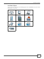
Icons Used in Figures
Figures in this User’s Guide may use the following generic icons. The NBG4615 icon is not an exact
representation of your device.
NBG4615
Computer
Notebook computer
Server
DSLAM
Firewall
Telephone
Switch
Router
Modem
NBG4615 User’s Guide
5
Safety Warnings
Safety Warnings
•
•
•
•
•
•
•
•
•
•
•
•
•
•
•
•
•
•
•
Do NOT use this product near water, for example, in a wet basement or near a swimming pool.
Do NOT expose your device to dampness, dust or corrosive liquids.
Do NOT store things on the device.
Do NOT install, use, or service this device during a thunderstorm. There is a remote risk of electric shock
from lightning.
Connect ONLY suitable accessories to the device.
Do NOT open the device or unit. Opening or removing covers can expose you to dangerous high voltage
points or other risks. ONLY qualified service personnel should service or disassemble this device. Please
contact your vendor for further information.
Make sure to connect the cables to the correct ports.
Place connecting cables carefully so that no one will step on them or stumble over them.
Always disconnect all cables from this device before servicing or disassembling.
Use ONLY an appropriate power adaptor or cord for your device.
Connect the power adaptor or cord to the right supply voltage (for example, 110V AC in North America or
230V AC in Europe).
Do NOT allow anything to rest on the power adaptor or cord and do NOT place the product where anyone can
walk on the power adaptor or cord.
Do NOT use the device if the power adaptor or cord is damaged as it might cause electrocution.
If the power adaptor or cord is damaged, remove it from the power outlet.
Do NOT attempt to repair the power adaptor or cord. Contact your local vendor to order a new one.
Do not use the device outside, and make sure all the connections are indoors. There is a remote risk of
electric shock from lightning.
Do NOT obstruct the device ventilation slots, as insufficient airflow may harm your device.
Antenna Warning! This device meets ETSI and FCC certification requirements when using the included
antenna(s). Only use the included antenna(s).
If you wall mount your device, make sure that no electrical lines, gas or water pipes will be damaged.
Your product is marked with this symbol, which is known as the WEEE mark. WEEE stands for
Waste Electronics and Electrical Equipment. It means that used electrical and electronic
products should not be mixed with general waste. Used electrical and electronic equipment
should be treated separately.
6
NBG4615 User’s Guide
Contents Overview
Contents Overview
User’s Guide ........................................................................................................................... 19
Introduction ................................................................................................................................21
The WPS Button ........................................................................................................................24
ZyXEL NetUSB Share Center Utility ..........................................................................................25
Connection Wizard .....................................................................................................................33
Introducing the Web Configurator ..............................................................................................43
Monitor .......................................................................................................................................49
NBG4615 Modes ........................................................................................................................55
Easy Mode .................................................................................................................................57
Router Mode ..............................................................................................................................68
Access Point Mode ....................................................................................................................75
Universal Repeater Mode ..........................................................................................................82
WISP Mode ................................................................................................................................90
WISP + UR Mode .......................................................................................................................99
Tutorials ...................................................................................................................................105
Technical Reference ............................................................................................................ 123
Wireless LAN ...........................................................................................................................125
IPv6 ..........................................................................................................................................143
WAN .........................................................................................................................................149
LAN ..........................................................................................................................................163
DHCP Server ...........................................................................................................................167
NAT ..........................................................................................................................................171
DDNS .......................................................................................................................................179
Static Route ..............................................................................................................................181
RIP ...........................................................................................................................................183
Firewall .....................................................................................................................................185
Content Filtering .......................................................................................................................190
Bandwidth Management ..........................................................................................................195
Remote Management ...............................................................................................................203
Universal Plug-and-Play (UPnP) ..............................................................................................205
Maintenance .............................................................................................................................213
Troubleshooting .......................................................................................................................223
NBG4615 User’s Guide
7
Contents Overview
8
NBG4615 User’s Guide
Table of Contents
Table of Contents
About This User's Guide .......................................................................................................... 3
Document Conventions ........................................................................................................... 4
Safety Warnings........................................................................................................................ 6
Contents Overview .................................................................................................................. 7
Table of Contents ..................................................................................................................... 9
Part I: User’s Guide ................................................................................19
Chapter 1
Introduction............................................................................................................................. 21
1.1 Overview ..............................................................................................................................21
1.2 Applications ..........................................................................................................................21
1.3 Ways to Manage the NBG4615 ...........................................................................................21
1.4 Good Habits for Managing the NBG4615 ............................................................................22
1.5 LEDs ....................................................................................................................................22
Chapter 2
The WPS Button...................................................................................................................... 24
2.1 Overview ..............................................................................................................................24
Chapter 3
ZyXEL NetUSB Share Center Utility...................................................................................... 25
3.1 Overview ..............................................................................................................................25
3.1.1 Quick Setup ................................................................................................................25
3.1.2 Installing ZyXEL NetUSB Share Center Utility ............................................................25
3.2 The ZyXEL NetUSB Share Center Utility .............................................................................26
3.2.1 The Menus ..................................................................................................................27
3.2.2 The ZyXEL NetUSB Share Center Configuration Window .........................................29
3.2.3 The Auto-Connect Printer List Window ......................................................................29
3.2.4 Exit the ZyXEL NetUSB Share Center Utility ..............................................................30
Chapter 4
Connection Wizard ................................................................................................................. 33
4.1 Overview ..............................................................................................................................33
4.2 Accessing the Wizard ...........................................................................................................33
NBG4615 User’s Guide
9
Table of Contents
4.3 Connect to Internet ...............................................................................................................34
4.3.1 Connection Type: DHCP ............................................................................................35
4.3.2 Connection Type: Static IP .........................................................................................35
4.3.3 Connection Type: PPPoE ...........................................................................................36
4.3.4 Connection Type: PPTP .............................................................................................37
4.3.5 Connection Type: L2TP ..............................................................................................38
4.4 Router Password ..................................................................................................................40
4.5 Wireless Security .................................................................................................................40
4.5.1 Wireless Security: No Security ...................................................................................40
4.5.2 Wireless Security: WPA-PSK/WPA2-PSK ..................................................................41
Chapter 5
Introducing the Web Configurator ........................................................................................ 43
5.1 Overview ..............................................................................................................................43
5.2 Accessing the Web Configurator ..........................................................................................43
5.2.1 Login Screen ..............................................................................................................43
5.2.2 Password Screen .......................................................................................................44
5.2.3 Home Screen ..............................................................................................................45
5.3 Resetting the NBG4615 .......................................................................................................47
5.3.1 How to Use the RESET Button ...................................................................................47
Chapter 6
Monitor..................................................................................................................................... 49
6.1 Overview ..............................................................................................................................49
6.2 What You Can Do ................................................................................................................49
6.3 The Log Screen ....................................................................................................................49
6.3.1 View Log .....................................................................................................................50
6.4 BW MGMT Monitor ..............................................................................................................51
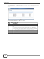
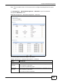
6.5 DHCP Table
......................................................................................................................51
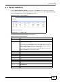
6.6 Packet Statistics
................................................................................................................53
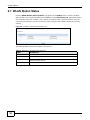
6.7 WLAN Station Status
........................................................................................................54
Chapter 7
NBG4615 Modes ..................................................................................................................... 55
7.1 Overview ..............................................................................................................................55
7.1.1 Web Configurator Modes ............................................................................................55
7.1.2 Device Modes .............................................................................................................55
Chapter 8
Easy Mode ............................................................................................................................... 57
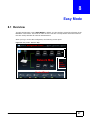
8.1 Overview ..............................................................................................................................57
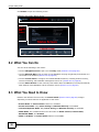
8.2 What You Can Do ................................................................................................................58
8.3 What You Need to Know ......................................................................................................58
10
NBG4615 User’s Guide
Table of Contents
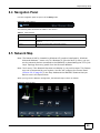
8.4 Navigation Panel ..................................................................................................................59
8.5 Network Map ........................................................................................................................59
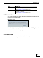
8.6 Control Panel .......................................................................................................................60
8.6.1 Game Engine ..............................................................................................................61
8.6.2 Power Saving .............................................................................................................61
8.6.3 Content Filter ..............................................................................................................63
8.6.4 Bandwidth MGMT .......................................................................................................63
8.6.5 Firewall .......................................................................................................................64
8.6.6 Wireless Security ........................................................................................................64
8.6.7 WPS ...........................................................................................................................66
8.7 Status Screen in Easy Mode ................................................................................................67
Chapter 9
Router Mode............................................................................................................................ 68
9.1 Overview ..............................................................................................................................68
9.2 Router Mode Status Screen .................................................................................................69
9.2.1 Navigation Panel ........................................................................................................72
Chapter 10
Access Point Mode................................................................................................................. 75
10.1 Overview ............................................................................................................................75
10.2 What You Can Do ..............................................................................................................75
10.3 What You Need to Know ....................................................................................................75
10.3.1 Setting your NBG4615 to AP Mode ..........................................................................76
10.3.2 Accessing the Web Configurator in Access Point Mode ...........................................76
10.3.3 Configuring your WLAN, Bandwidth Management and Maintenance Settings .........77
10.4 AP Mode Status Screen .....................................................................................................78
10.5 LAN Screen ........................................................................................................................80
Chapter 11
Universal Repeater Mode....................................................................................................... 82
11.1 Overview ............................................................................................................................82
11.2 What You Can Do ...............................................................................................................82
11.3 What You Need to Know ....................................................................................................83
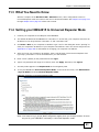
11.4 Setting your NBG4615 to Universal Repeater Mode ..........................................................83
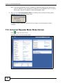
11.5 Universal Repeater Mode Status Screen ...........................................................................84
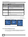
11.6 Universal Repeater Screen ................................................................................................86
11.6.1 No Security ...............................................................................................................87
11.6.2 Static WEP ................................................................................................................88
11.6.3 WPA(2)-PSK .............................................................................................................89
Chapter 12
WISP Mode .............................................................................................................................. 90
NBG4615 User’s Guide
11
Table of Contents
12.1 Overview ............................................................................................................................90
12.2 What You Can Do ..............................................................................................................90
12.3 What You Need to Know ....................................................................................................90
12.3.1 Setting your NBG4615 to WISP Mode .....................................................................91
12.3.2 Accessing the Web Configurator in WISP Mode ......................................................91
12.4 WISP Mode Status Screen .................................................................................................92
12.5 Wireless LAN General Screen ...........................................................................................95
12.5.1 Static WEP ................................................................................................................96
12.5.2 WPA(2)-PSK .............................................................................................................97
12.5.3 Site Survey Screen ...................................................................................................98
Chapter 13
WISP + UR Mode ..................................................................................................................... 99
13.1 Overview ............................................................................................................................99
13.2 What You Can Do ..............................................................................................................99
13.3 What You Need to Know ....................................................................................................99
13.3.1 Setting your NBG4615 to WISP + UR Mode ..........................................................100
13.3.2 Accessing the Web Configurator in WISP Mode ....................................................100
13.4 WISP + UR Mode Status Screen .....................................................................................101
Chapter 14
Tutorials ................................................................................................................................. 105
14.1 Overview ..........................................................................................................................105
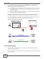
14.2 Set Up a Wireless Network with WPS ..............................................................................105
14.2.1 Push Button Configuration (PBC) ...........................................................................105
14.2.2 PIN Configuration ...................................................................................................106
14.3 Configure Wireless Security without WPS .......................................................................107
14.3.1 Configure Your Notebook .......................................................................................109
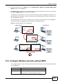
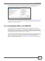
14.4 Using Multiple SSIDs on the NBG4615 ............................................................................ 111
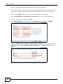
14.4.1 Configuring Security Settings of Multiple SSIDs ..................................................... 112
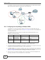
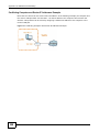
14.5 Connecting the NBG4615 (in Universal Repeater Mode) to an AP or Wireless Router ... 115
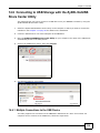
14.6 Connecting to USB Storage with the ZyXEL NetUSB Share Center Utility ...................... 119
14.6.1 Multiple Connections to the USB Device ................................................................ 119
14.7 Automatically Connecting to a USB Printer ......................................................................121
Part II: Technical Reference.................................................................123
Chapter 15
Wireless LAN......................................................................................................................... 125
15.1 Overview ..........................................................................................................................125
15.1.1 What You Can Do ...................................................................................................125
12
NBG4615 User’s Guide
Table of Contents
15.1.2 What You Should Know ..........................................................................................126
15.2 General Wireless LAN Screen ........................................................................................128
15.2.1 Guest WLAN ...........................................................................................................129
15.3 Wireless Security Screen .................................................................................................132
15.3.1 No Security .............................................................................................................132
15.3.2 WEP Encryption .....................................................................................................132
15.3.3 WPA-PSK/WPA2-PSK ............................................................................................134
15.4 MAC Filter ........................................................................................................................135
15.5 Wireless LAN Advanced Screen ......................................................................................136
15.6 Quality of Service (QoS) Screen ......................................................................................137
15.7 WPS Screen .....................................................................................................................137
15.8 WPS Station Screen .........................................................................................................139
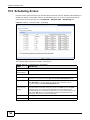
15.9 Scheduling Screen ...........................................................................................................140
15.10 WDS Screen ..................................................................................................................141
Chapter 16
IPv6 ........................................................................................................................................ 143
16.1 Overview ..........................................................................................................................143
16.1.1 What You Need to Know .........................................................................................143
16.2 The IPv6 Screen ..............................................................................................................144
16.2.1 IPv6 Connection: Ethernet ......................................................................................145
16.2.2 IPv6 Connection: DHCPv6 .....................................................................................146
16.2.3 IPv6 Connection: Link-local only ............................................................................147
Chapter 17
WAN ....................................................................................................................................... 149
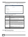
17.1 Overview ..........................................................................................................................149
17.2 What You Can Do ............................................................................................................149
17.3 What You Need To Know .................................................................................................149
17.3.1 Configuring Your Internet Connection .....................................................................150
17.3.2 Multicast .................................................................................................................151
17.4 Internet Connection ..........................................................................................................151
17.4.1 Ethernet Encapsulation ..........................................................................................151
17.4.2 PPPoE Encapsulation ............................................................................................153
17.4.3 PPTP Encapsulation ...............................................................................................155
17.4.4 L2TP Encapsulation ...............................................................................................157
17.5 Advanced WAN Screen ...................................................................................................159
17.6 IGMP Snooping Screen ...................................................................................................160
Chapter 18
LAN ........................................................................................................................................ 163
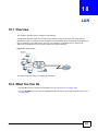
18.1 Overview ..........................................................................................................................163
18.2 What You Can Do ............................................................................................................163
NBG4615 User’s Guide
13
Table of Contents
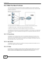
18.3 What You Need To Know .................................................................................................164
18.3.1 IP Pool Setup ..........................................................................................................164
18.3.2 LAN TCP/IP ............................................................................................................164
18.3.3 IP Alias ...................................................................................................................164
18.4 LAN IP Screen .................................................................................................................165
18.5 IP Alias Screen .................................................................................................................165
Chapter 19
DHCP Server ......................................................................................................................... 167
19.1 Overview ..........................................................................................................................167
19.1.1 What You Can Do ...................................................................................................167
19.1.2 What You Need To Know ........................................................................................167
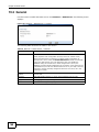
19.2 General ............................................................................................................................168
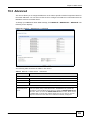
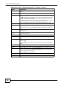
19.3 Advanced
......................................................................................................................169
Chapter 20
NAT......................................................................................................................................... 171
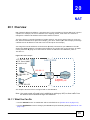
20.1 Overview
.......................................................................................................................171
20.1.1 What You Can Do ...................................................................................................171
20.1.2 What You Need To Know ........................................................................................172
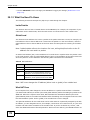
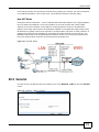
20.2 General ............................................................................................................................173
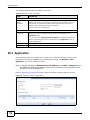
20.3 Application .......................................................................................................................174
20.4 Advanced .........................................................................................................................176
20.5 Technical Reference .........................................................................................................177
20.5.1 NATPort Forwarding: Services and Port Numbers .................................................177
20.5.2 NAT Port Forwarding Example ...............................................................................177
20.5.3 Trigger Port Forwarding ..........................................................................................177
20.5.4 Trigger Port Forwarding Example ...........................................................................178
20.5.5 Two Points To Remember About Trigger Ports ......................................................178
Chapter 21
DDNS...................................................................................................................................... 179
21.1 Overview .........................................................................................................................179
21.1.1 What You Need To Know ........................................................................................179
21.2 General
..........................................................................................................................180
Chapter 22
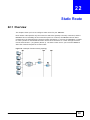
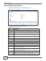
Static Route ........................................................................................................................... 181
22.1 Overview
.......................................................................................................................181
22.2 IP Static Route Screen ....................................................................................................182
Chapter 23
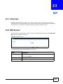
RIP.......................................................................................................................................... 183
14
NBG4615 User’s Guide
Table of Contents
23.1 Overview .........................................................................................................................183
23.2 RIP Screen .....................................................................................................................183
Chapter 24
Firewall .................................................................................................................................. 185
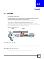
24.1 Overview
........................................................................................................................185
24.1.1 What You Can Do ...................................................................................................185
24.1.2 What You Need To Know ........................................................................................185
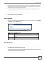
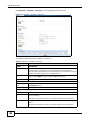
24.2 General ...........................................................................................................................187
24.3 Services ...........................................................................................................................187
Chapter 25
Content Filtering ................................................................................................................... 190
25.1 Overview ..........................................................................................................................190
25.1.1 What You Need To Know ........................................................................................190
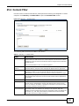
25.2 Content Filter ....................................................................................................................191
25.3 Technical Reference .........................................................................................................192
25.3.1 Customizing Keyword Blocking URL Checking ......................................................192
Chapter 26
Bandwidth Management....................................................................................................... 195
26.1 Overview .........................................................................................................................195
26.2 What You Can Do ............................................................................................................195
26.3 What You Need To Know .................................................................................................196
26.4 General Screen ...............................................................................................................196
26.5 Advanced Screen ............................................................................................................196
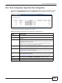
26.5.1 Rule Configuration: Application Rule Configuration ..............................................199
26.5.2 Rule Configuration: User Defined Service Rule Configuration
............................200
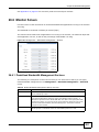
26.6 Monitor Screen .................................................................................................................201
26.6.1 Predefined Bandwidth Management Services ........................................................201
Chapter 27
Remote Management............................................................................................................ 203
27.1 Overview ..........................................................................................................................203
27.2 What You Need to Know ..................................................................................................203
27.2.1 Remote Management and NAT ..............................................................................203
27.2.2 System Timeout .....................................................................................................203
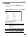
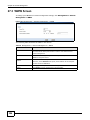
27.3 WWW Screen
................................................................................................................204
Chapter 28
Universal Plug-and-Play (UPnP).......................................................................................... 205
28.1 Overview .........................................................................................................................205
28.2 What You Need to Know ..................................................................................................205
NBG4615 User’s Guide
15
Table of Contents
28.2.1 NAT Traversal .........................................................................................................205
28.2.2 Cautions with UPnP ................................................................................................205
28.3 UPnP Screen ..................................................................................................................206
28.4 Technical Reference .........................................................................................................206
28.4.1 Using UPnP in Windows XP Example ....................................................................206
28.4.2 Web Configurator Easy Access ..............................................................................209
Chapter 29
Maintenance .......................................................................................................................... 213
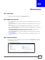
29.1 Overview ..........................................................................................................................213
29.2 What You Can Do ............................................................................................................213
29.3 General Screen ................................................................................................................213
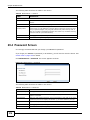
29.4 Password Screen .............................................................................................................214
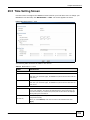
29.5 Time Setting Screen .........................................................................................................215
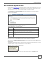
29.6 Firmware Upgrade Screen ...............................................................................................217
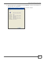
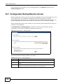
29.7 Configuration Backup/Restore Screen .............................................................................218
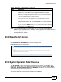
29.8 Reset/Restart Screen .......................................................................................................219
29.9 System Operation Mode Overview ..................................................................................219
29.10 Sys OP Mode Screen .....................................................................................................221
Chapter 30
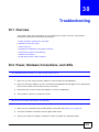
Troubleshooting.................................................................................................................... 223
30.1 Overview ..........................................................................................................................223
30.2 Power, Hardware Connections, and LEDs .......................................................................223
30.3 NBG4615 Access and Login ............................................................................................224
30.4 Internet Access ................................................................................................................226
30.5 Resetting the NBG4615 to Its Factory Defaults ...............................................................227
30.6 Wireless Router/AP Troubleshooting ...............................................................................227
30.7 USB Device Problems ......................................................................................................229
30.8 ZyXEL Share Center Utility Problems ..............................................................................230
Appendix A Product Specifications ...................................................................................... 233
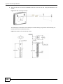
30.9 Wall-mounting Instructions ...............................................................................................235
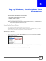
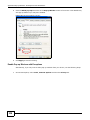
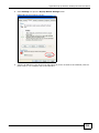
Appendix B Pop-up Windows, JavaScript and Java Permissions ....................................... 237
Appendix C IP Addresses and Subnetting........................................................................... 249
Appendix D Setting Up Your Computer’s IP Address .......................................................... 259
Appendix E Wireless LANs.................................................................................................. 287
Appendix F Common Services ............................................................................................ 301
Appendix G IPv6.................................................................................................................. 305
16
NBG4615 User’s Guide
Table of Contents
Appendix H Open Software Announcements ...................................................................... 313
Appendix I Legal Information ............................................................................................... 347
Index ...................................................................................................................................... 355
NBG4615 User’s Guide
17
Table of Contents
18
NBG4615 User’s Guide
P ART I
User’s Guide
19
20
C HAPT ER
1
Introduction
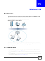
1.1 Overview
This chapter introduces the main features and applications of the NBG4615.
The NBG4615 extends the range of your existing wired network without additional wiring, providing
easy network access to mobile users. You can set up a wireless network with other IEEE 802.11b/g/
n compatible devices.
A range of services such as a firewall and content filtering are also available for secure Internet
computing.
Note: Be sure to install the ZyXEL NetUSBTM Share Center Utility (for NetUSB
functionality) from the included disc, or download the latest version from the
zyxel.com website.
1.2 Applications
Your can create the following networks using the NBG4615:
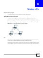
• Wired. You can connect network devices via the Ethernet ports of the NBG4615 so that they can
communicate with each other and access the Internet.
• Wireless. Wireless clients can connect to the NBG4615 to access network resources.
• WAN. Connect to a broadband modem/router for Internet access.
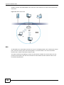
• WPS. Create an instant network connection with another WPS-compatible device, sharing your
network connection with it.
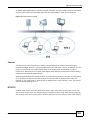
• NetUSB. The NBG4615 allows you to connect a USB device (such as printer, scanner, or portable
hard disk) directly to the USB port and then share that device over the Internet. You can also
connect a USB to the NBG4615, which can then share up to 3 additional USB devices with the
rest of your personal home network.
1.3 Ways to Manage the NBG4615
Use any of the following methods to manage the NBG4615.
• WPS (Wi-Fi Protected Setup). You can use the WPS button or the WPS section of the Web
Configurator to set up a wireless network with your ZyXEL Device.
• Web Configurator. This is recommended for everyday management of the NBG4615 using a
(supported) web browser.
NBG4615 User’s Guide
21
Chapter 1 Introduction
1.4 Good Habits for Managing the NBG4615
Do the following things regularly to make the NBG4615 more secure and to manage the NBG4615
more effectively.
• Change the password. Use a password that’s not easy to guess and that consists of different
types of characters, such as numbers and letters.
• Write down the password and put it in a safe place.
• Back up the configuration (and make sure you know how to restore it). Restoring an earlier
working configuration may be useful if the device becomes unstable or even crashes. If you
forget your password, you will have to reset the NBG4615 to its factory default settings. If you
backed up an earlier configuration file, you would not have to totally re-configure the NBG4615.
You could simply restore your last configuration.
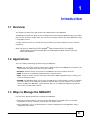
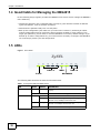
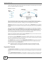
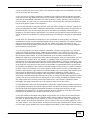
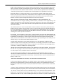
1.5 LEDs
Figure 1 Front Panel
LAN 1-4
WAN
Power
USB 1-2
WLAN/WPS
The following table describes the LEDs and the WPS button.
Table 1 Front panel LEDs and WPS button
LED
COLOR
STATUS
DESCRIPTION
Power
Green
On
The NBG4615 is receiving power and functioning
properly.
Off
LAN 1-4
Green
Amber
Off
22
The NBG4615 is not receiving power.
On
The NBG4615’s LAN connection is ready.
Blinking
The NBG4615 is sending/receiving data through the
LAN with a 10/100Mbps transmission rate.
Blinking
The NBG4615 is sending/receiving data through the
LAN with a 1000Mbps transmission rate.
The LAN connection is not ready, or has failed.
NBG4615 User’s Guide
Chapter 1 Introduction
Table 1 Front panel LEDs and WPS button (continued)
LED
COLOR
WAN
Green
Amber
STATUS
On
The NBG4615’s WAN connection is ready.
Blinking
The NBG4615 is sending/receiving data through the
WAN with a 10/100Mbps transmission rate.
Blinking
The NBG4615 is sending/receiving data through the
WAN with a 1000Mbps transmission rate.
Off
WLAN/WPS
Green
DESCRIPTION
The WAN connection is not ready, or has failed.
On
The NBG4615 is ready, but is not sending/receiving
data through the wireless LAN.
Blinking
The NBG4615 is sending/receiving data through the
wireless LAN.
The NBG4615 is negotiating a WPS connection with a
wireless client.
Off
USB 1-2
Green
Off
NBG4615 User’s Guide
The wireless LAN is not ready or has failed.
On
The NBG4615 has a USB device installed.
Blinking
The NBG4615 is transmitting and/or receiving data
from routers through an installed USB device.
There is no USB device connected to the NBG4615.
23
C HAPT ER
2
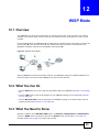
The WPS Button
2.1 Overview
Your NBG4615 supports WiFi Protected Setup (WPS), which is an easy way to set up a secure
wireless network. WPS is an industry standard specification, defined by the WiFi Alliance.
WPS allows you to quickly set up a wireless network with strong security, without having to
configure security settings manually. Each WPS connection works between two devices. Both
devices must support WPS (check each device’s documentation to make sure).
Depending on the devices you have, you can either press a button (on the device itself, or in its
configuration utility) or enter a PIN (a unique Personal Identification Number that allows one device
to authenticate the other) in each of the two devices. When WPS is activated on a device, it has two
minutes to find another device that also has WPS activated. Then, the two devices connect and set
up a secure network by themselves.
For more information on using WPS, see Section 14.2 on page 105.
NBG4615 User’s Guide
24
C HAPT ER
3
ZyXEL NetUSB Share Center Utility
3.1 Overview
The ZyXEL NetUSB Share Center Utility allows you to work with the USB devices that are connected
directly to the NBG4615 as if they are connected directly to your computer. This allows you to easily
share USB-based devices such as printers, scanners, portable hard disks, MP3 players, faxes, and
digital cameras (to name a few) with all the other people in your home or office as long as they are
connected to the NBG4615 and have the ZyXEL NetUSB Share Center Utility installed.
Note: Be sure to install the ZyXEL NetUSB Share Center Utility (for NetUSB functionality)
from the included disc, or download the latest version from the zyxel.com website.
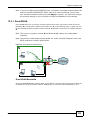
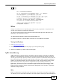
3.1.1 Quick Setup
This section shows you how to get started using the ZyXEL NetUSB Share Center Utility.
1
Install the ZyXEL NetUSB Share Center Utility on each computer connected to the NBG4615.
2
Connect a USB device to the USB port on the NBG4615.
Note: If you are connecting multiple devices to the NBG4615, first connect a USB hub to
the NBG4615 then connect your other USB devices to it.
3
Run the ZyXEL NetUSB Share Center Utility to display a list of all connected USB devices, then use
it to connect your computer to them.
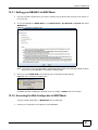
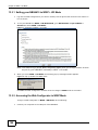
3.1.2 Installing ZyXEL NetUSB Share Center Utility
Before you can access USB devices connected to the NBG4615, you must first install the ZyXEL
NetUSB Share Center Utility on any computer on your LAN to which you want to allow access to
these devices.
Note: In order to properly use the utility with your NBG4615, ensure that the NBG4615
firmware is version v1.00(BWQ.0) or higher. See Chapter 29 on page 217 for
information on updating your device’s firmware.
To install the ZyXEL NetUSB Share Center Utility:
1
Insert the disc that came with your NBG4615 into your computer’s disc drive.
2
Run the Setup program by double-clicking it and then follow the on-screen instructions for
installing it on your computer.
NBG4615 User’s Guide
25
Chapter 3 ZyXEL NetUSB Share Center Utility
Note: The following operating systems are supported: Windows XP/Vista/7 (32 and 64-bit
versions), and Mac OS X 10.6.
3
To open the ZyXEL NetUSB Share Center Utility, double-click its system tray icon.
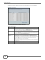
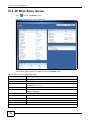
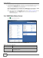
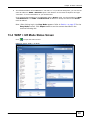
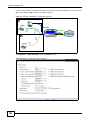
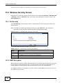
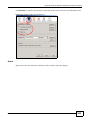
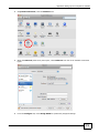
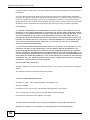
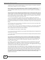
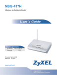
3.2 The ZyXEL NetUSB Share Center Utility
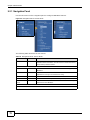
This section describes the ZyXEL NetUSB Share Center Utility main window.
Figure 2 ZyXEL NetUSB Share Center Utility Main Window
26
NBG4615 User’s Guide
Chapter 3 ZyXEL NetUSB Share Center Utility
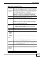
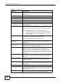
The following table describes the icons in this window.
Table 2 ZyXEL NetUSB Share Center Utility Main Window Icons
ICON
DESCRIPTION
Configure Server
Click to open the NBG4615’s built-in Web Configurator, which you can use to
set up the NBG4615 (see Chapter 5 on page 43 for details).
Auto-Connect Printer
You can set the selected printer to ‘auto-connect’ after you have connected it
to your computer during inital connection. If the printer is auto-connected to
your computer, they will always be connected over the network. You do not
need to configure it manually each time.
Note: If the computer is connecting to the shared USB printer for the first time,
you need to click Connect and setup the printer before you can use the
Auto-Connect Printer function. See Chapter 14 on page 121 for more
details.
Note: You first must install the appropriate drivers for the printer that you intend
to use.
Connect
Select a USB device and then click this button to connect to it. Your computer
can connect to as many USB devices as are connected to the NBG4615.
Disconnect
Select a device to which your computer is connected and then click this
button to disconnect from it.
Request to Connect
Some USB devices may not allow automatic connections over the network. If
so, select the device in question and click this button to issue a request to
connect to it.
Network Scanner
Click this to open the scanner options on your computer for working with a
scanner connected to the network.
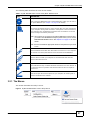
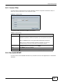
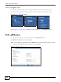
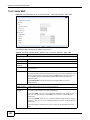
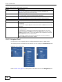
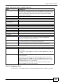
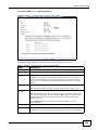
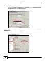
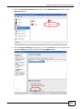
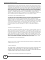
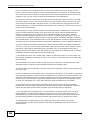
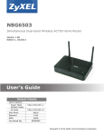
3.2.1 The Menus
This section describes the utility’s menus.
Figure 3 ZyXEL NetUSB Share Center Utility Menus
NBG4615 User’s Guide
27
Chapter 3 ZyXEL NetUSB Share Center Utility
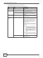
The following table describes the menus in this screen.
Table 3 ZyXEL NetUSB Share Center Utility Main Screen Menus
MENU
ITEM
DESCRIPTION
System
Exit
This closes the ZyXEL NetUSB Share Center
Utility.
Tools
Configuration
This opens the ZyXEL NetUSB Share Center
Utility configuration window.
Auto-Connect Printer List
This opens the list window that displays all
of the printing devices connected to the
NBG4615.
Help
About
This opens the about window, which
provides information of the utility software
and driver versions.
Auto-Connect
Printer
Set Auto-Connect Printer
You can set the selected printer to ‘autoconnect’ after you have connected it to your
computer during inital connection. If the
printer is auto-connected to your computer,
they will always be connected over the
network. You do not need to configure it
manually each time.
Click this to show your installed printer list
and select the one you want to set as autoconnected.
Note: If the computer is connecting to the
shared USB printer for the first time,
you need to click Connect and setup
the printer before you can use the
Auto-Connect Printer function. See
Chapter 14 on page 121 for more
details.
Note: You first must install the appropriate
drivers for the printer that you intend
to use.
Delete Auto-Connect Printer
28
This removes the auto-connect option from
the selected printer.
NBG4615 User’s Guide
Chapter 3 ZyXEL NetUSB Share Center Utility
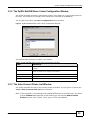
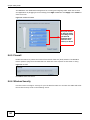
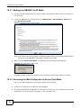
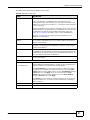
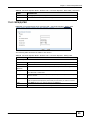
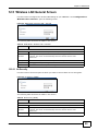
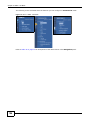
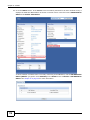
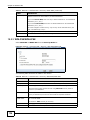
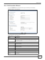
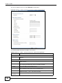
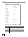
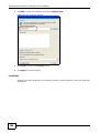
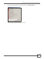
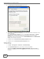
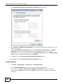
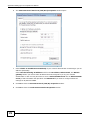
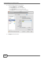
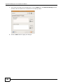
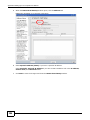
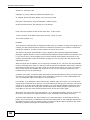
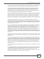
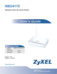
3.2.2 The ZyXEL NetUSB Share Center Configuration Window
This section describes the utility’s configuration window, which allows you to set certain options for
the utility. These options do not apply to the USB devices connected to the NBG4615.
You can open it by clicking the Tools > Configuration menu command.
Figure 4 ZyXEL NetUSB Share Center Utility Configuration Window
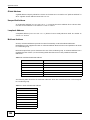
The following table describes the labels in this window.
Table 4 ZyXEL NetUSB Share Center Utility Configuration Window
LABEL
DESCRIPTION
Basic
Select this to run the utility automatically when you log into or start up
Windows.
Language
Select a language for the ZyXEL NetUSB Share Center Utility. You must
restart the utility for the change to take effect.
OK
Click this to save your changes and close the window.
Cancel
Click this cancel to close the window without saving.
Apply
Click this to save your changes without closing the window.
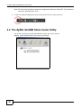
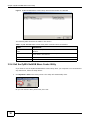
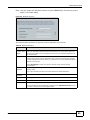
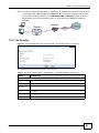
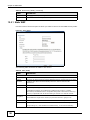
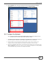
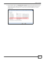
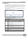
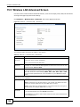
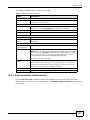
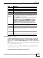
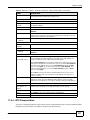
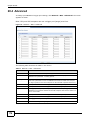
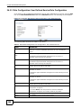
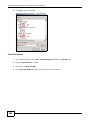
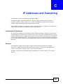
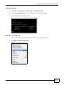
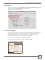
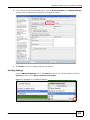
3.2.3 The Auto-Connect Printer List Window
This section describes the utility’s auto-connect printer list window. You can open it by clicking the
Tools > Auto-Connect Printer List menu command.
Note: If the computer is connecting to the shared USB printer for the first time, you need
to click Connect and setup the printer before you can use the Auto-Connect
Printer function. See Chapter 14 on page 121 for more details.
NBG4615 User’s Guide
29
Chapter 3 ZyXEL NetUSB Share Center Utility
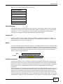
Figure 5 ZyXEL NetUSB Share Center Utility Auto-Connect Printer List Window
The following table describes the labels in this screen.
Table 5 ZyXEL NetUSB Share Center Utility Auto-Connect Printer List Window
LABEL
DESCRIPTION
Server IP & Printer
Name
Displays a list of print server IPs and printer names connected to this
NBG4615.
Windows Printer Name
Displays a corresponding list of Windows printer names connected to this
devices listed in the other list.
Delete
Select an printer from the list and click this to remove it.
Close
Click this to close the window.
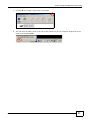
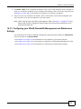
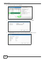
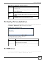
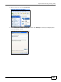
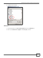
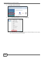
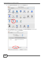
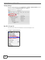
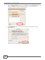
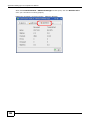
3.2.4 Exit the ZyXEL NetUSB Share Center Utility
If you want to exit the ZyXEL NetUSB Share Center Utility when your computer is not connected to
any USB device, follow the steps below:
1
Click System > Exit on the Utility screen. The Utility will automatically close.
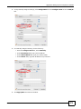
Or you can close the Utlity screen first, then exit:
30
NBG4615 User’s Guide
Chapter 3 ZyXEL NetUSB Share Center Utility
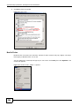
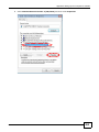
1
Click the X on the upper-right corner of the Utility:
2
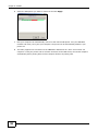
This will close the Utility screen to an icon at the system tray of your computer. Right-click on the
Utility’s icon and click Exit.
NBG4615 User’s Guide
31
Chapter 3 ZyXEL NetUSB Share Center Utility
32
NBG4615 User’s Guide
C HAPT ER
4
Connection Wizard
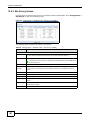
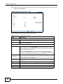
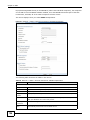
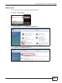
4.1 Overview
This chapter provides information on the wizard setup screens in the Web Configurator.
The Web Configurator’s wizard setup helps you configure your device to access the Internet. Refer
to your ISP for your Internet account information. Leave a field blank if you don’t have that
information.
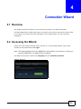
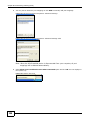
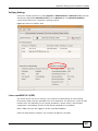
4.2 Accessing the Wizard
Launch your web browser and type "http://192.168.1.1" as the website address. Type "1234"
(default) as the password and click Login.
Note: The Wizard appears when the NBG4615 is accessed for the first time or when you
reset the NBG4615 to its default factory settings.
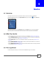
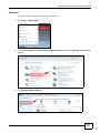
The Wizard screen opens. Choose your Language and click Connect to Internet.
Figure 6 Welcome
NBG4615 User’s Guide
33
Chapter 4 Connection Wizard
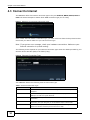
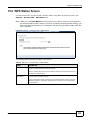
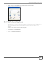
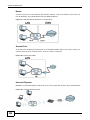
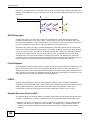
4.3 Connect to Internet
The NBG4615 offers five Internet connection types. They are Static IP, DHCP, PPPoE, PPTP or
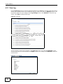
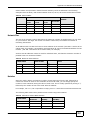
L2TP. The wizard attempts to detect which WAN connection type you are using.
Figure 7 Detecting your Internet Connection Type
If the wizard does not detect a connection type, you must select one from the drop-down list box.
Check with your ISP to make sure you use the correct type.
Note: If you get an error message, check your hardware connections. Make sure your
Internet connection is up and running.
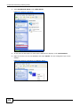
The following screen depends on your Internet connection type. Enter the details provided by your
Internet Service Provider (ISP) in the fields (if any).
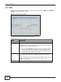
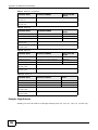
Figure 8 Internet Connection Type
Your NBG4615 detects the following Internet Connection type.
Table 6 Internet Connection Type
34
CONNECTION TYPE
DESCRIPTION
Static IP
Select the Static IP if an administrator assigns the IP address of your
computer.
DHCP
Select the DHCP (Dynamic Host Configuration Protocol) option when the
WAN port is used as a regular Ethernet.
PPPoE
Select the PPPoE (Point-to-Point Protocol over Ethernet) option for a dial-up
connection.
PPTP
Select the PPTP (Point-to-Point Tunneling Protocol) option for a dial-up
connection, and your ISP gave you an IP address and/or subnet mask.
L2TP
Select the L2TP (Layer 2 Tunnel Protocol) if you are connecting to another
device over another network (like the Internet or VPN).
NBG4615 User’s Guide
Chapter 4 Connection Wizard
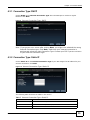
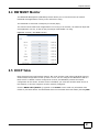
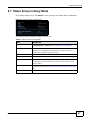
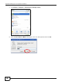
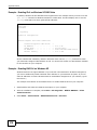
4.3.1 Connection Type: DHCP
Choose DHCP as the Internet Connection Type when the WAN port is used as a regular
Ethernet. Click Next.
Figure 9 Internet Connection Type: DHCP
Note: If you get an error screen after clicking Next, you might have selected the wrong
Internet Connection type. Click Back, make sure your Internet connection is
working and select the right Connection Type. Contact your ISP if you are not sure
of your Internet Connection type.
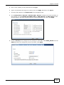
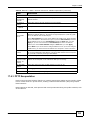
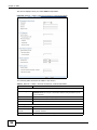
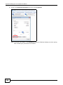
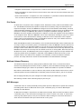
4.3.2 Connection Type: Static IP
Choose Static IP as the Internet Connection Type if your ISP assigned an IP address for your
Internet connection. Click Next.
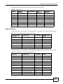
Figure 10 Internet Connection Type: Static IP
The following table describes the labels in this screen.
Table 7 Internet Connection Type: Static IP
LABEL
DESCRIPTION
Internet Connection Type
Select the Static IP option.
IP Address
Enter the IP address provided by your ISP.
Subnet Mask
Enter the IP subnet mask in this field.
NBG4615 User’s Guide
35
Chapter 4 Connection Wizard
Table 7 Internet Connection Type: Static IP (continued)
LABEL
DESCRIPTION
Default Gateway
Enter the gateway IP address in this field.
Primary DNS
DNS (Domain Name System) is for mapping a domain name to its
corresponding IP address and vice versa. The DNS server is extremely
important because without it, you must know the IP address of a
computer before you can access it. The NBG4615 uses a system DNS
server (in the order you specify here) to resolve domain names for DDNS
and the time server.
Enter the primary DNS server's IP address in the fields provided.
Secondary DNS
Enter the secondary DNS server's IP address in the fields provided.
Exit
Click this to close the wizard screen without saving.
Back
Click this to return to the previous screen.
Next
Click this to continue.
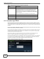
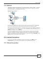
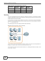
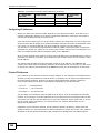
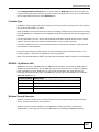
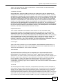
4.3.3 Connection Type: PPPoE
Point-to-Point Protocol over Ethernet (PPPoE) functions as a dial-up connection. PPPoE is an IETF
(Internet Engineering Task Force) standard specifying how a host personal computer interacts with
a broadband modem (for example DSL, cable, wireless, etc.) to achieve access to high-speed data
networks.
For the service provider, PPPoE offers an access and authentication method that works with existing
access control systems (for instance, RADIUS).
One of the benefits of PPPoE is the ability to let end users access one of multiple network services,
a function known as dynamic service selection. This enables the service provider to easily create
and offer new IP services for specific users.
Operationally, PPPoE saves significant effort for both the subscriber and the ISP/carrier, as it
requires no specific configuration of the broadband modem at the subscriber's site.
By implementing PPPoE directly on the NBG4615 (rather than individual computers), the computers
on the LAN do not need PPPoE software installed, since the NBG4615 does that part of the task.
Furthermore, with NAT, all of the LAN's computers will have Internet access.
Figure 11 Internet Connection Type: PPPoE
36
NBG4615 User’s Guide
Chapter 4 Connection Wizard
The following table describes the labels in this screen.
Table 8 Internet Connection Type: PPPoE
LABEL
DESCRIPTION
Internet
Connection Type
Select the PPPoE option for a dial-up connection.
Dynamic IP
Select this radio button if your ISP did not assign you a fixed IP address.
Static IP
Select this radio button, provided by your ISP to give the NBG4615 a fixed,
unique IP address.
IP Address
Type the name of your service provider.
User Name
Type the user name given to you by your ISP.
Password
Type the password associated with the user name above.
Exit
Click this to close the wizard screen without saving.
Back
Click this to return to the previous screen.
Next
Click this to continue.
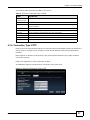
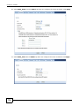
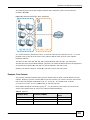
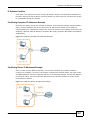
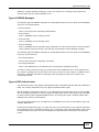
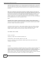
4.3.4 Connection Type: PPTP
Point-to-Point Tunneling Protocol (PPTP) is a network protocol that enables transfers of data from a
remote client to a private server, creating a Virtual Private Network (VPN) using TCP/IP-based
networks.
PPTP supports on-demand, multi-protocol, and virtual private networking over public networks,
such as the Internet.
Refer to the appendix for more information on PPTP.
The NBG4615 supports one PPTP server connection at any given time.
Figure 12 Internet Connection Type: PPTP
NBG4615 User’s Guide
37
Chapter 4 Connection Wizard
The following table describes the fields in this screen
Table 9 Internet Connection Type: PPTP
LABEL
DESCRIPTION
Internet
Connection Type
Select PPTP from the drop-down list box. To configure a PPTP client, you must
configure the User Name and Password fields for a PPP connection and the
PPTP parameters for a PPTP connection.
Dynamic IP
Select this radio button if your ISP did not assign you a fixed IP address.
Static IP
Select this radio button, provided by your ISP to give the NBG4615 a fixed,
unique IP address.
PPTP Address
Type the (static) IP address assigned to you by your ISP.
PPTP Subnet Mask
Type the subnet mask assigned to you by your ISP (if given).
PPTP Gateway IP
Address
Type the gateway IP address of the PPTP server.
PPTP Server IP
Address
Type the server IP address of the PPTP server.
User Name
Type the user name given to you by your ISP.
Password
Type the password associated with the User Name above.
Exit
Click this to close the wizard screen without saving.
Back
Click this to return to the previous screen.
Next
Click this to continue.
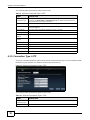
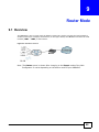
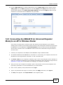
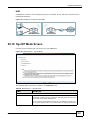
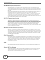
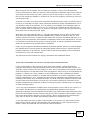
4.3.5 Connection Type: L2TP
The Layer 2 Tunneling Protocol (L2TP) works at layer 2 (the data link layer) to tunnel network traffic
between two peer devices over another network (like the Internet).
Figure 13 Internet Connection Type: L2TP
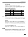
The following table describes the fields in this screen
Table 10 Internet Connection Type: L2TP
38
LABEL
DESCRIPTION
Internet
Connection Type
Select L2TP from the drop-down list box.
Dynamic IP
Select this radio button if your ISP did not assign you a fixed IP address.
NBG4615 User’s Guide
Chapter 4 Connection Wizard
Table 10 Internet Connection Type: L2TP (continued)
LABEL
DESCRIPTION
Static IP
Select this radio button, provided by your ISP to give the NBG4615 a fixed,
unique IP address.
L2TP Address
Type the (static) IP address assigned to you by your ISP.
L2TP Subnet Mask
Type the subnet mask assigned to you by your ISP (if given).
L2TP Gateway IP
Address
Type the gateway IP address of the L2TP server.
L2TP Server IP
Address
Type the server IP address of the L2TP server.
User Name
Type the user name given to you by your ISP.
Password
Type the password associated with the User Name above.
Exit
Click this to close the wizard screen without saving.
Back
Click this to return to the previous screen.
Next
Click this to continue.
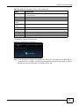
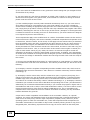
The NBG4615 connects to the Internet.
Figure 14 Connecting to the Internet
Note: If the Wizard successfully connects to the Internet, it proceeds to the next step. If
you get an error message, go back to the previous screen and make sure you have
entered the correct information provided by your ISP.
NBG4615 User’s Guide
39
Chapter 4 Connection Wizard
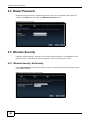
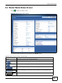
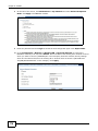
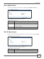
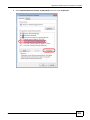
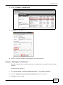
4.4 Router Password
Change the login password in the following screen. Enter the new password and retype it to
confirm. Click Next to proceed with the Wireless Security screen.
Figure 15 Router Password
4.5 Wireless Security
Configure Wireless Settings. Configure the wireless network settings on your NBG4615 in the
following screen. The fields that show up depend on the kind of security you select.
4.5.1 Wireless Security: No Security
Choose No Security in the Wireless Security screen to let wireless devices within range access
your wireless network.
Figure 16 Wireless Security: No Security
40
NBG4615 User’s Guide
Chapter 4 Connection Wizard
The following table describes the labels in this screen.
Table 11 Wireless Security: No Security
LABEL
DESCRIPTION
Wireless
Network
Name (SSID)
Enter a descriptive name (up to 32 printable 7-bit ASCII characters) for the wireless
LAN.
Security mode
Select a Security level from the drop-down list box.
If you change this field on the NBG4615, make sure all wireless stations use the
same SSID in order to access the network.
Choose No Security to have no wireless LAN security configured. If you do not
enable any wireless security on your NBG4615, your network is accessible to any
wireless networking device that is within range.
Exit
Click this to close the wizard screen without saving.
Back
Click this to return to the previous screen.
Next
Click this to continue.
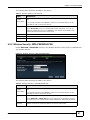
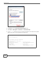
4.5.2 Wireless Security: WPA-PSK/WPA2-PSK
Choose WPA-PSK or WPA2-PSK security in the Wireless Security screen to set up a password for
your wireless network.
Figure 17 Wireless Security: WPA-PSK/WPA2-PSK
The following table describes the labels in this screen.
Table 12 Wireless Security: WPA-PSK/WPA2-PSK
LABEL
DESCRIPTION
Wireless
Network
Name (SSID)
Enter a descriptive name (up to 32 printable 7-bit ASCII characters) for the wireless
LAN.
Security mode
Select a Security level from the drop-down list box.
If you change this field on the NBG4615, make sure all wireless stations use the
same SSID in order to access the network.
Choose WPA-PSK or WPA2-PSK security to configure a Pre-Shared Key. Choose
this option only if your wireless clients support WPA-PSK or WPA2-PSK respectively.
Wireless
password
NBG4615 User’s Guide
Type from 8 to 63 case-sensitive ASCII characters. You can set up the most secure
wireless connection by configuring WPA in the wireless LAN screens.
41
Chapter 4 Connection Wizard
Table 12 Wireless Security: WPA-PSK/WPA2-PSK (continued)
LABEL
DESCRIPTION
Verify
Password
Retype the password to confirm.
Exit
Click this to close the wizard screen without saving.
Back
Click this to return to the previous screen.
Next
Click this to continue.
Congratulations! Open a web browser, such as Internet Explorer, to visit your favorite website.
Note: If you cannot access the Internet when your computer is connected to one of the
NBG4615’s LAN ports, check your connections. Then turn the NBG4615 off, wait for
a few seconds then turn it back on. If that does not work, log in to the web
configurator again and check you have typed all information correctly. See the
User’s Guide for more suggestions.
Figure 18 Congratulations
You can also click GO to open the Easy Mode Web Configurator of your NBG4615.
You have successfully set up your NBG4615 to operate on your network and access the Internet.
You are now ready to connect wirelessly to your NBG4615 and access the Internet.
42
NBG4615 User’s Guide
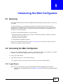
C HAPT ER
5
Introducing the Web Configurator
5.1 Overview
This chapter describes how to access the NBG4615 Web Configurator and provides an overview of
its screens.
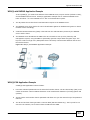
The Web Configurator is an HTML-based management interface that allows easy setup and
management of the NBG4615 via Internet browser. Use Internet Explorer 6.0 and later versions,
Mozilla Firefox 3 and later versions, or Safari 2.0 and later versions. The recommended screen
resolution is 1024 by 768 pixels.
In order to use the Web Configurator you need to allow:
• Web browser pop-up windows from your device. Web pop-up blocking is enabled by default in
Windows XP SP (Service Pack) 2.
• JavaScript (enabled by default).
• Java permissions (enabled by default).
Refer to the Troubleshooting chapter (Chapter 30 on page 223) to see how to make sure these
functions are allowed in Internet Explorer.
5.2 Accessing the Web Configurator
1
Make sure your NBG4615 hardware is properly connected and prepare your computer or computer
network to connect to the NBG4615 (refer to the Quick Start Guide).
2
Launch your web browser.
3
Type "http://192.168.1.1" as the website address.
Your computer must be in the same subnet in order to access this website address.
5.2.1 Login Screen
Note: If this is the first time you are accessing the Web Configurator, you may be
redirected to the Wizard. Refer to Chapter 4 on page 33 for the Connection Wizard
screens.
NBG4615 User’s Guide
43
Chapter 5 Introducing the Web Configurator
The Web Configurator initially displays the following login screen.
Figure 19 Login screen
The following table describes the labels in this screen.
Table 13 Login screen
LABEL
DESCRIPTION
Password
Type "1234" (default) as the password.
Language
Select the language you want to use to configure the Web Configurator. Click
Login.
This shows the current weather, either in celsius or fahrenheit, of the city you
specify in Section 5.2.3.1 on page 46.
This shows the time (hh:mm:ss) and date (yyyy:mm:dd) of the timezone you
select in Section 5.2.3.2 on page 46 or Section 29.5 on page 215. The time is in
24-hour format, for example 15:00 is 3:00 PM.
5.2.2 Password Screen
You should see a screen asking you to change your password (highly recommended) as shown
next.
Figure 20 Change Password Screen
44
NBG4615 User’s Guide
Chapter 5 Introducing the Web Configurator
The following table describes the labels in this screen.
Table 14 Change Password Screen
LABEL
DESCRIPTION
New Password
Type a new password.
Retype to Confirm Retype the password for confirmation.
Apply
Click Apply to save your changes back to the NBG4615.
Ignore
Click Ignore if you do not want to change the password this time.
Note: The management session automatically times out when the time period set in the
Administrator Inactivity Timer field expires (default five minutes; go to Chapter
29 on page 213 to change this). Simply log back into the NBG4615 if this happens.
5.2.3 Home Screen
If you have previously logged into the Web Configurator but did not click Logout, you may be
redirected to the Home screen.
You can also open this screen by clicking Home (
mode screens.
or
) in the Easy Mode or Expert
The Home screen displays as follows.
Figure 21 Home Screen
The following table describes the labels in this screen.
Table 15 Home Screen
LABEL
DESCRIPTION
Go
Click this to open the Easy Mode Web Configurator.
Language
Select a language to go to the Easy mode Web Configurator in that language and
click Login.
NBG4615 User’s Guide
45
Chapter 5 Introducing the Web Configurator
Table 15 Home Screen (continued)
LABEL
DESCRIPTION
(This is just an example). This shows the current weather, either in celsius or
fahrenheit, of the city you specify in Section 5.2.3.1 on page 46.
(This is just an example). This shows the time (hh:mm:ss) and date
(yyyy:mm:dd) of the timezone you select in Section 5.2.3.2 on page 46 or
Section 29.5 on page 215.
5.2.3.1 Weather Edit
You can change the temperature unit and select the location for which you want to know the
weather.
Click the
icon to change the Weather display.
Figure 22 Change Weather
The following table describes the labels in this screen.
Table 16 Change Weather
LABEL
DESCRIPTION
o
Choose which temperature unit you want the NBG4615 to display.
o
C or F
Change Location
Select the location for which you want to know the weather. If the city you want
is not listed, choose one that is closest to it.
Finish
Click this to apply the settings and refresh the date and time display.
5.2.3.2 Time/Date Edit
One timezone can cover more than one country. You can choose a particular country in which the
NBG4615 is located and have the NBG4615 display and use the current time and date for its logs.
Click the
icon to change the Weather display.
Figure 23 Change Password Screen
The following table describes the labels in this screen.
Table 17 Change Password Screen
LABEL
DESCRIPTION
Change time zone
Select the specific country whose current time and date you want the NBG4615
to display.
Finish
Click this to apply the settings and refresh the weather display.
Note: You can also edit the timezone in Section 29.5 on page 215.
46
NBG4615 User’s Guide
Chapter 5 Introducing the Web Configurator
5.3 Resetting the NBG4615
If you forget your password or IP address, or you cannot access the Web Configurator, you will need
to use the RESET button at the back of the NBG4615 to reload the factory-default configuration
file. This means that you will lose all configurations that you had previously saved, the password
will be reset to “1234” and the IP address will be reset to “192.168.1.1”.
5.3.1 How to Use the RESET Button
1
Make sure the power LED is on.
2
Press the RESET button for longer than 1 second to restart/reboot the NBG4615.
3
Press the RESET button for longer than 5 seconds to set the NBG4615 back to its factory-default
configurations.
NBG4615 User’s Guide
47
Chapter 5 Introducing the Web Configurator
48
NBG4615 User’s Guide
C HAPT ER
6
Monitor
6.1 Overview
This chapter discusses read-only information related to the device state of the NBG4615.
To access the Monitor screens, go to Expert Mode after login, then click
show the complete menu.
. Click open all to
You can also click the links in the Summary table of the Status screen to view the bandwidth
consumed, packets sent/received as well as the status of clients connected to the NBG4615.
6.2 What You Can Do
• Use the Log screen to see the logs for the activity on the NBG4615 (Section 6.3 on page 49).
• Use the BW MGMT Monitor screen to view the amount of network bandwidth that applications
running in the network are using (Section 6.4 on page 51).
• Use the DHCP Table screen to view information related to your DHCP status (Section 6.5 on
page 51).
• use the Packet Statistics screen to view port status, packet specific statistics, the "system up
time" and so on (Section 6.6 on page 53).
• Use the WLAN Station Status screen to view the wireless stations that are currently associated
to the NBG4615 (Section 6.7 on page 54).
6.3 The Log Screen
The Web Configurator allows you to look at all of the NBG4615’s logs in one location.
NBG4615 User’s Guide
49
Chapter 6 Monitor
6.3.1 View Log
Use the View Log screen to see the logged messages for the NBG4615. The log wraps around and
deletes the old entries after it fills. Select what logs you want to see from the Display drop list. The
log choices depend on your settings in the Log Settings screen. Click Refresh to renew the log
screen. Click Clear to delete all the logs.
Figure 24 View Log
You can configure which logs to display in the View Log screen. Go to the Log Settings screen
and select the logs you wish to display. Click Apply to save your settings. Click Refresh to start the
screen afresh.
Figure 25 Log Settings
50
NBG4615 User’s Guide
Chapter 6 Monitor
6.4 BW MGMT Monitor
The Bandwidth Management (BW MGMT) Monitor allows you to view the amount of network
bandwidth that applications running in the network are using.
The bandwidth is measured in kilobytes per second (kbps).
The monitor shows what kinds of applications are running in the network, the maximum kbps that
each application can use, as well as the percentage of bandwidth it is using.
Figure 26 Summary: BW MGMT Monitor
6.5 DHCP Table
DHCP (Dynamic Host Configuration Protocol, RFC 2131 and RFC 2132) allows individual clients to
obtain TCP/IP configuration at start-up from a server. You can configure the NBG4615’s LAN as a
DHCP server or disable it. When configured as a server, the NBG4615 provides the TCP/IP
configuration for the clients. If DHCP service is disabled, you must have another DHCP server on
that network, or else the computer must be manually configured.
Click the DHCP Table (Details...) hyperlink in the Status screen. Read-only information here
relates to your DHCP status. The DHCP table shows current DHCP client information (including MAC
NBG4615 User’s Guide
51
Chapter 6 Monitor
Address, IP Address, and Expiration time) of all network clients using the NBG4615’s DHCP
server.
Figure 27 Summary: DHCP Table
The following table describes the labels in this screen.
Table 18 Summary: DHCP Table
LABEL
DESCRIPTION
#
This is the index number of the host computer.
MAC Address
This field shows the MAC address of the computer with the name in the Host Name
field.
Every Ethernet device has a unique MAC (Media Access Control) address which
uniquely identifies a device. The MAC address is assigned at the factory and consists
of six pairs of hexadecimal characters, for example, 00:A0:C5:00:00:02.
52
IP Address
This field displays the IP address relative to the # field listed above.
Expires in
This field displays the time when the IP address and MAC address association ends.
Refresh
Click Refresh to renew the screen.
NBG4615 User’s Guide
Chapter 6 Monitor
6.6 Packet Statistics
Click the Packet Statistics (Details...) hyperlink in the Status screen. Read-only information
here includes port status, packet specific statistics and the "system up time". The Poll Interval(s)
field is configurable and is used for refreshing the screen.
Figure 28 Summary: Packet Statistics
The following table describes the labels in this screen.
Table 19 Summary: Packet Statistics
LABEL
DESCRIPTION
Port
This is the NBG4615’s port type.
Status
For the LAN ports, this displays the port speed and duplex setting or Down
when the line is disconnected.
For the WAN port, it displays the port speed and duplex setting if you’re using
Ethernet encapsulation and Idle (line (ppp) idle), Dial (starting to trigger a
call) and Drop (dropping a call) if you're using PPPoE or PPTP encapsulation.
This field displays Down when the line is disconnected.
For the WLAN, it displays the maximum transmission rate when the WLAN is
enabled and Down when the WLAN is disabled.
TxPkts
This is the number of transmitted packets on this port.
RxPkts
This is the number of received packets on this port.
Collisions
This is the number of collisions on this port.
Tx B/s
This displays the transmission speed in bytes per second on this port.
Rx B/s
This displays the reception speed in bytes per second on this port.
Up Time
This is the total time the NBG4615 has been for each session.
System Up Time
This is the total time the NBG4615 has been on.
Poll Interval(s)
Enter the time interval in seconds for refreshing statistics in this field.
Set Interval
Click this button to apply the new poll interval you entered in the Poll
Interval(s) field.
Stop
Click Stop to stop refreshing statistics.
NBG4615 User’s Guide
53
Chapter 6 Monitor
6.7 WLAN Station Status
Click the WLAN Station Status (Details...) hyperlink in the Status screen. View the wireless
stations that are currently associated to the NBG4615 in the Association List. Association means
that a wireless client (for example, your network or computer with a wireless network card) has
connected successfully to the AP (or wireless router) using the same SSID, channel and security
settings.
Figure 29 Summary: Wireless Association List
The following table describes the labels in this screen.
Table 20 Summary: Wireless Association List
54
LABEL
DESCRIPTION
#
This is the index number of an associated wireless station.
MAC Address
This field displays the MAC address of an associated wireless station.
Association Time
This field displays the time a wireless station first associated with the
NBG4615’s WLAN network.
Refresh
Click Refresh to reload the list.
NBG4615 User’s Guide
C HAPT ER
7
NBG4615 Modes
7.1 Overview
This chapter introduces the different modes available on your NBG4615. First, the term “mode”
refers to two things in this User’s Guide.
• Web Configurator mode. This refers to the Web Configurator interface you want to use for
editing NBG4615 features.
• Device mode. This is the operating mode of your NBG4615, or simply how the NBG4615 is
being used in the network.
7.1.1 Web Configurator Modes
This refers to the configuration interface of the Web Configurator, which has two modes:
• Easy: The Web Configurator shows this mode by default. Refer to Chapter 8 on page 57 for more
information on the screens in this mode. This interface may be sufficient for users who just want
to use the device.
• Expert: Advanced users can change to this mode to customize all the functions of the NBG4615.
Click Expert Mode after logging into the Web Configurator. The User’s Guide Chapter 5 on page
43 through Chapter 29 on page 221 discusses the screens in this mode.
7.1.2 Device Modes
This refers to the operating mode of the NBG4615, which can act as a:
• Router: This is the default device mode of the NBG4615. Use this mode to connect the local
network to another network, like the Internet. Go to Section 9.2 on page 69 to view the Status
screen in this mode.
• Access Point: Use this mode if you want to extend your network by allowing network devices to
connect to the NBG4615 wirelessly. Go to Section 10.4 on page 78 to view the Status screen in
this mode.
• Universal Repeater: In this mode, the NBG4615 can be an access point and a wireless client at
the same time. Use this mode if there is an existing wireless router or access point in your
network and you also want to allow clients to connect to the NBG4615. Go to Section 11.5 on
page 84 to view the Status screen in this mode.
• WISP: Use this mode if there is an existing wireless router or access point in the network to
which you want to connect your local network. Go to Section 11.5 on page 84 to view the Status
screen in this mode.
• WISP + UR: In this mode, the NBG4615 has the same function as in WISP mode. In addition, it
can provide WiFi function to the clients on the LAN side. Go to Section 13.4 on page 101 to view
the Status screen in this mode.
NBG4615 User’s Guide
55
Chapter 7 NBG4615 Modes
For more information on these modes and to change the mode of your NBG4615, refer to Chapter
29 on page 221.
The menu for changing device modes is available in Expert mode only.
Note: Choose your Device Mode carefully to avoid having to change it later.
When changing to another mode, the IP address of the NBG4615 changes. The running applications
and services of the network devices connected to the NBG4615 can be interrupted.
In WISP and WISP + UR mode, you should know the SSID and wireless security details of the
access point to which you want to connect.
56
NBG4615 User’s Guide
C HAPT ER
8
Easy Mode
8.1 Overview
The Web Configurator is set to Easy Mode by default. You can configure several key features of the
NBG4615 in this mode. This mode is useful to users who are not fully familiar with some features
that are usually intended for network administrators.
When you log in to the Web Configurator, the following screen opens.
Figure 30 Easy Mode: Network Map
Navigation Panel
Network Map
Go to
Status
Screen
Control Panel
NBG4615 User’s Guide
57
Chapter 8 Easy Mode
Click Status to open the following screen.
Figure 31 Easy Mode: Status Screen
Navigation Panel
Go to
Network
Map
Screen
Status Screen
Control Panel
8.2 What You Can Do
You can do the following in this mode:
• Use this Navigation Panel to opt out of the Easy mode (Section 8.4 on page 59).
• Use the Network Map screen to check if your NBG4615 can ping the gateway and whether it is
connected to the Internet (Section 8.5 on page 59).
• Use the Control Panel to configure and enable NBG4615 features, including wireless security,
wireless scheduling and bandwidth management and so on (Section 8.6 on page 60).
• Use the Status Screen to view read-only information about the NBG4615, including the WAN IP,
MAC Address of the NBG4615 and the firmware version (Section 8.7 on page 67).
8.3 What You Need to Know
Between the different device modes, the Control Panel (Section 8.6 on page 60) changes
depending on which features are applicable to the mode:
• Router Mode: All Control Panel features are available.
• Access Point Mode: Only Power Saving and Wireless Security are available.
• Universal Repeater Mode: Only Power Saving and Wireless Security are available.
• WISP Mode: The available features for this mode are Game Console, Content Filter,
Bandwidth MGMT, and Firewall.
• WISP + UR Mode: All Control Panel features are available.
58
NBG4615 User’s Guide
Chapter 8 Easy Mode
8.4 Navigation Panel
Use this navigation panel to opt out of the Easy mode.
Figure 32 Control Panel
The following table describes the labels in this screen.
Table 21 Control Panel
ITEM
DESCRIPTION
Home
Click this to go to the Login page.
Expert Mode
Click this to change to Expert mode and customize features of the
NBG4615.
Logout
Click this to end the Web Configurator session.
8.5 Network Map
Note: The Network MAP is viewable by Windows XP (need to install patch), Windows
Vista and Windows 7 users only. For Windows XP (Service Pack 2) users, you can
see the network devices connected to the NBG4615 by downloading the LLTD (Link
Layer Topology Discovery) patch from the Microsoft Website.
Note: Don’t worry if the Network Map does not display in your web browser. This feature
may not be supported by your system. You can still configure the Control Panel
(Section 8.6 on page 60) in the Easy Mode and the NBG4615 features that you
want to use in the Expert Mode.
When you log into the Network Configurator, the Network Map is shown as follows.
Figure 33 Network Map
NBG4615 User’s Guide
59
Chapter 8 Easy Mode
The line connecting the NBG4615 to the gateway becomes green when the NBG4615 is able to ping
the gateway. It becomes red when the ping initiating from the NBG4615 does not get a response
from the gateway. The same rule applies to the line connecting the gateway to the Internet.
You can also view the devices (represented by icons indicating the kind of network device)
connected to the NBG4615, including those connecting wirelessly. Right-click on the NBG4615 icon
to refresh the network map and go to the Wizard. Right click on the other icons to view information
about the device.
8.6 Control Panel
The features configurable in Easy Mode are shown in the Control Panel.
Figure 34 Control Panel
Switch ON to enable the feature. Otherwise, switch OFF. If the feature is turned on, the green light
flashes. If it is turned off, the red light flashes.
Additionally, click the feature to open a screen where you can edit its settings.
The following table describes the labels in this screen.
Table 22 Control Panel
ITEM
DESCRIPTION
Game Engine
Switch ON to maximize bandwidth for gaming traffic in your network.
Otherwise, switch OFF.
Refer to Section 8.6.1 on page 61 to see this screen.
Power Saving
Click this to schedule the wireless feature of the NBG4615.
Disabling the wireless function helps lower the energy consumption of the
NBG4615.
Switch ON to apply wireless scheduling. Otherwise, switch OFF.
Refer to Section 8.6.2 on page 61 to see this screen.
Content Filter
Click this to restrict access to certain websites, based on keywords
contained in URLs, to which you do not want users in your network to
open.
Switch ON to apply website filtering. Otherwise, switch OFF.
Refer to Section 8.6.3 on page 63 to see this screen.
Bandwidth MGMT
Click this to edit bandwidth management for predefined applications.
Switch ON to have the NBG4615 management bandwidth for uplink and
downlink traffic according to an application or service. Otherwise, switch
OFF.
Refer to Section 8.6.4 on page 63 to see this screen.
60
NBG4615 User’s Guide
Chapter 8 Easy Mode
Table 22 Control Panel (continued)
ITEM
DESCRIPTION
Firewall
Switch ON to ensure that your network is protected from Denial of Service
(DoS) attacks. Otherwise, switch OFF.
Refer to Section 8.6.5 on page 64 to see this screen.
Wireless Security
Click this to configure the wireless security, such as SSID, security mode
and WPS key on your NBG4615.
Refer to Section 8.6.6 on page 64 to see this screen.
8.6.1 Game Engine
When this feature is enabled, the NBG4615 maximizes the bandwidth for gaming traffic that
it forwards out through an interface.
Figure 35 Game Engine
Note: When this is switched on, the Game Console tab in the Bandwidth Mgmt screen is
automatically positioned on top.
Turn this off if your network is not using gaming.
Click OK to close this screen.
8.6.2 Power Saving
Use this screen to set the day of the week and time of the day when your wireless LAN is turned on
and off. Wireless LAN scheduling is disabled by default.
NBG4615 User’s Guide
61
Chapter 8 Easy Mode
Disabling the wireless capability lowers the energy consumption of the of the NBG4615.
Figure 36 Power Saving
The following table describes the labels in this screen.
Table 23 Power Saving
LABEL
DESCRIPTION
WLAN Status
Select On or Off to specify whether the Wireless LAN is turned on or off
(depending on what you selected in the WLAN Status field). This field works in
conjunction with the Day and For the following times fields.
Day
Select Everyday or the specific days to turn the Wireless LAN on or off.
If you select Everyday you can not select any specific days. This field works in
conjunction with the For the following times field.
For the following
times (24-Hour
Format)
Select a begin time using the first set of hour and minute (min) drop down
boxes and select an end time using the second set of hour and minute (min)
drop down boxes. If you have chosen On earlier for the WLAN Status the
Wireless LAN will turn on between the two times you enter in these fields. If you
have chosen Off earlier for the WLAN Status the Wireless LAN will turn off
between the two times you enter in these fields.
In this time format, midnight is 00:00 and progresses up to 24:00. For example,
6:00 PM is 18:00.
62
Apply
Click Apply to save your changes back to the NBG4615.
Reset
Click Reset to begin configuring this screen afresh.
NBG4615 User’s Guide
Chapter 8 Easy Mode
8.6.3 Content Filter
Use this screen to restrict access to certain websites, based on keywords contained in URLs, to
which you do not want users in your network to open.
Figure 37 Content Filter
The following table describes the labels in this screen.
Table 24 Content Filter
LABEL
DESCRIPTION
Add
Click Add after you have typed a keyword.
Repeat this procedure to add other keywords. Up to 64 keywords are allowed.
Note: The NBG4615 does not recognize wildcard characters as keywords.
When you try to access a web page containing a keyword, you will get a
message telling you that the content filter is blocking this request.
Delete
Highlight a keyword in the text box and click Delete to remove it. The keyword
disappears from the text box after you click Apply.
Apply
Click Apply to save your changes.
Cancel
Click Cancel to close this screen without saving any changes.
8.6.4 Bandwidth MGMT
Use this screen to set bandwidth allocation to pre-defined services and applications for bandwidth
allocation.
NBG4615 User’s Guide
63
Chapter 8 Easy Mode
The NBG4615 uses bandwidth management for incoming and outgoing traffic. Rank the services
and applications by dragging them accordingly from High to Low and click Apply. Click Cancel to
close the screen.
Figure 38 Bandwidth MGNT
Use your mouse
to drag the items
according to how
you want to
prioritize them.
Left-click and
slide up or down.
8.6.5 Firewall
Enable this feature to protect the network from Denial of Service (DoS) attacks. The NBG4615
blocks repetitive pings from the WAN that can otherwise cause systems to slow down or hang.
Figure 39 Firewall
Click OK to close this screen.
8.6.6 Wireless Security
Use this screen to configure security for your the Wireless LAN. You can enter the SSID and select
the wireless security mode in the following screen.
64
NBG4615 User’s Guide
Chapter 8 Easy Mode
Note: You can enable the Wireless function of your NBG4615 by first turning on the
switch in the back panel.
Figure 40 Wireless Security
The following table describes the general wireless LAN labels in this screen.
Table 25 Wireless Security
LABEL
DESCRIPTION
Wireless
Network Name
(SSID)
(Service Set IDentity) The SSID identifies the Service Set with which a wireless
station is associated. Wireless stations associating to the access point (AP) must
have the same SSID. Enter a descriptive name (up to 32 keyboard characters) for
the wireless LAN.
Security mode
Select WPA-PSK or WPA2-PSK to add security on this wireless network. The
wireless clients which want to associate to this network must have same wireless
security settings as this device. After you select to use a security, additional options
appears in this screen.
Select No Security to allow any client to connect to this network without
authentication.
Wireless
password
This field appears when you choose wither WPA-PSK or WPA2-PSK as the
security mode.
Type a pre-shared key from 8 to 63 case-sensitive keyboard characters.
Verify
password
Type the password again to confirm.
Apply
Click Apply to save your changes back to the NBG4615.
Cancel
Click Cancel to close this screen.
WPS
Click this to configure the WPS screen.
You can transfer the wireless settings configured here (Wireless Security screen)
to another wireless device that supports WPS.
NBG4615 User’s Guide
65
Chapter 8 Easy Mode
8.6.7 WPS
Use this screen to add a wireless station to the network using WPS. Click WPS in the Wireless
Security to open the following screen.
Figure 41 Wireless Security: WPS
The following table describes the labels in this screen.
Table 26 Wireless Security: WPS
LABEL
DESCRIPTION
Wireless Security
Click this to go back to the Wireless Security screen.
WPS
Create a secure wireless network simply by pressing a button.
The NBG4615 scans for a WPS-enabled device within the range and performs
wireless security information synchronization.
Note: After you click the WPS button on this screen, you have to press a similar
button in the wireless station utility within 2 minutes. To add the second
wireless station, you have to press these buttons on both device and the
wireless station again after the first 2 minutes.
Register
Create a secure wireless network simply by entering a wireless client's PIN
(Personal Identification Number) in the NBG4615’s interface and pushing this
button.
Type the same PIN number generated in the wireless station’s utility. Then click
Register to associate to each other and perform the wireless security
information synchronization.
Exit
66
Click Exit to close this screen.
NBG4615 User’s Guide
Chapter 8 Easy Mode
8.7 Status Screen in Easy Mode
In the Network Map screen, click Status to view read-only information about the NBG4615.
Figure 42 Status Screen in Easy Mode
The following table describes the labels in this screen.
Table 27 Status Screen in Easy Mode
ITEM
DESCRIPTION
Name
This is the name of the NBG4615 in the network. You can change this in
the Maintenance > General screen in Section 29.3 on page 213.
Time
This is the current system date and time.
The date is in YYYY:MM:DD (Year-Month-Day) format. The time is in
HH:MM:SS (Hour:Minutes:Seconds) format.
WAN IP
This is the IP address of the WAN port.
MAC Address
This is the MAC address of the NBG4615.
Firmware Version
This shows the firmware version of the NBG4615.
The firmware version format shows the trunk version, model code and
release number.
Wireless Network Name
This shows the SSID of the wireless network. You can configure this in the
Wireless Security screen (Section 8.6.6 on page 64; Section 15.2 on page
128).
Security
This shows the wireless security used by the NBG4615.
NBG4615 User’s Guide
67
C HAPT ER
9
Router Mode
9.1 Overview
The NBG4615 is set to router mode by default. Routers are used to connect the local network to
another network (for example, the Internet). In the figure below, the NBG4615 connects the local
network (LAN1 ~ LAN4) to the Internet.
Figure 43 NBG4615 Network
Modem
Note: The Status screen is shown after changing to the Expert mode of the Web
Configurator. It varies depending on the device mode of your NBG4615.
NBG4615 User’s Guide
68
Chapter 9 Router Mode
9.2 Router Mode Status Screen
Click
to open the status screen.
Figure 44 Status Screen: Router Mode
The following table describes the icons shown in the Status screen.
Table 28 Status Screen Icon Key: Router Mode
ICON
DESCRIPTION
Logout
Click this at any time to exit the Web Configurator.
Click this to go to the Home page. See Chapter 6 on page 49.
Click this icon to view copyright and a link for related product information.
Click this icon to go to Easy Mode. See Chapter 8 on page 57.
Select a number of seconds or None from the drop-down list box to refresh all screen
statistics automatically at the end of every time interval or to not refresh the screen
statistics.
Click this button to refresh the status screen statistics.
NBG4615 User’s Guide
69
Chapter 9 Router Mode
Table 28 Status Screen Icon Key: Router Mode (continued)
ICON
DESCRIPTION
Click this icon to see the Status page. The information in this screen depends on the
device mode you select.
Click this icon to see the Monitor navigation menu.
Click this icon to see the Configuration navigation menu.
Click this icon to see the Maintenance navigation menu.
The following table describes the labels shown in the Status screen.
Table 29 Status Screen: Router Mode
LABEL
DESCRIPTION
Device Information
Host Name
This is the System Name you enter in the Maintenance > General screen. It is
for identification purposes.
Firmware Version
This is the firmware version and the date created.
Sys OP Mode
This is the device mode (Section 7.1.2 on page 55) to which the NBG4615 is set Router Mode.
WAN Information
- MAC Address
This shows the WAN Ethernet adapter MAC Address of your device.
- IP Address
This shows the WAN port’s IP address.
- IP Subnet Mask
This shows the WAN port’s subnet mask.
- Default Gateway
This shows the WAN port’s gateway IP address.
- DHCP
This shows the LAN port’s DHCP role - Client or None.
LAN Information
- MAC Address
This shows the LAN Ethernet adapter MAC Address of your device.
- IP Address
This shows the LAN port’s IP address.
- IP Subnet Mask
This shows the LAN port’s subnet mask.
- DHCP
This shows the LAN port’s DHCP role - Server or Disable.
WLAN Information
- WLAN OP Mode
This is the device mode (Section 7.1.2 on page 55) to which the NBG4615’s
wireless LAN is set - Access Point Mode.
- MAC Address
This shows the wireless adapter MAC Address of your device.
- Status
This shows the current status of the Wireless LAN - ON or OFF.
- Name (SSID)
This shows a descriptive name used to identify the NBG4615 in the wireless LAN.
- Channel
This shows the channel number which you select manually.
- Operating Channel
This shows the channel number which the NBG4615 is currently using over the
wireless LAN.
- Security Mode
This shows the level of wireless security the NBG4615 is using.
- 802.11 Mode
This shows the wireless standard.
- WPS
This displays Configured when the WPS has been set up.
This displays Unconfigured if the WPS has not been set up.
Click the status to display Network > Wireless LAN > WPS screen.
70
NBG4615 User’s Guide
Chapter 9 Router Mode
Table 29 Status Screen: Router Mode (continued)
LABEL
DESCRIPTION
System Status
Item
This column shows the type of data the NBG4615 is recording.
Data
This column shows the actual data recorded by the NBG4615.
System Up Time
This is the total time the NBG4615 has been on.
Current Date/Time
This field displays your NBG4615’s present date and time.
System Resource
- CPU Usage
This displays what percentage of the NBG4615’s processing ability is currently
used. When this percentage is close to 100%, the NBG4615 is running at full load,
and the throughput is not going to improve anymore. If you want some applications
to have more throughput, you should turn off other applications (for example,
using bandwidth management.)
- Memory Usage
This shows what percentage of the heap memory the NBG4615 is using.
System Setting
- Firewall
This shows whether the firewall is enabled or not.
- Bandwidth
Management
This shows whether the bandwidth management is enabled or not.
- UPnP
This shows whether UPnP is enabled or not.
- Configuration Mode
This shows the web configurator mode you are viewing - Expert.
IPv6 Status
Item
This column shows the type of data the NBG4615 is recording.
Data
This column shows the actual data recorded by the NBG4615.
IPv6 Connection Type
This shows the type of IPv6 connection that is currently in use.
LAN IPv6 Link Local Address
This shows the NBG4615’s LAN IPv6 link local address.
Summary
BW MGMT Monitor
Click Details... to go to the Monitor > BW MGMT Monitor screen (Section 6.4 on
page 51). Use this screen to view the amount of network bandwidth that
applications running in the network are using.
DHCP Table
Click Details... to go to the Monitor > DHCP Table screen (Section 6.5 on page
51). Use this screen to view current DHCP client information.
Packet Statistics
Click Details... to go to the Monitor > Packet Statistics screen (Section 6.6 on
page 53). Use this screen to view port status and packet specific statistics.
WLAN Station Status
Click Details... to go to the Monitor > WLAN Station Status screen (Section 6.7
on page 54). Use this screen to view the wireless stations that are currently
associated to the NBG4615.
Interface Status
Interface
This displays the NBG4615 port types. The port types are: WAN, LAN and WLAN.
Status
For the LAN and WAN ports, this field displays Down (line is down) or Up (line is up
or connected).
For the WLAN, it displays Up when the WLAN is enabled or Down when the WLAN
is disabled.
Rate
For the LAN ports, this displays the port speed and duplex setting or N/A when the
line is disconnected.
For the WAN port, it displays the port speed and duplex setting if you’re using
Ethernet encapsulation. This field displays N/A when the line is disconnected.
For the WLAN, it displays the maximum transmission rate when the WLAN is
enabled and N/A when the WLAN is disabled.
NBG4615 User’s Guide
71
Chapter 9 Router Mode
9.2.1 Navigation Panel
Use the sub-menus on the navigation panel to configure NBG4615 features.
Figure 45 Navigation Panel: Router Mode
The following table describes the sub-menus.
Table 30 Navigation Panel: Router Mode
LINK
TAB
Status
FUNCTION
This screen shows the NBG4615’s general device, system and
interface status information. Use this screen to access the wizard,
and summary statistics tables.
MONITOR
Log
Use this screen to view the list of activities recorded by your
NBG4615.
BW MGMT
Use this screen to view the amount of network bandwidth that
applications running in the network are using.
DHCP Table
Use this screen to view current DHCP client information.
Packet Statistics
Use this screen to view port status and packet specific statistics.
WLAN Station
Status
Use this screen to view the wireless stations that are currently
associated to the NBG4615.
CONFIGURATION
Network
72
NBG4615 User’s Guide
Chapter 9 Router Mode
Table 30 Navigation Panel: Router Mode (continued)
LINK
TAB
FUNCTION
General
Use this screen to configure wireless LAN.
Security
Use this screen to configure the level of wireless security for the
NBG4615.
MAC Filter
Use the MAC filter screen to configure the NBG4615 to block
access to devices or block the devices from accessing the
NBG4615.
Advanced
This screen allows you to configure advanced wireless settings.
QoS
Use this screen to configure Wi-Fi Multimedia Quality of Service
(WMM QoS). WMM QoS allows you to prioritize wireless traffic
according to the delivery requirements of individual services.
WPS
Use this screen to configure WPS.
WPS Station
Use this screen to add a wireless station using WPS.
Scheduling
Use this screen to schedule the times the Wireless LAN is enabled.
WDS
Use this screen to set up Wireless Distribution System (WDS) on
your NBG4615.
IPv6
IPv6
Use this screen to set the IPv6 settings for your NBG4615.
WAN
Internet
Connection
This screen allows you to configure ISP parameters, WAN IP
address assignment, DNS servers and the WAN MAC address.
Advanced
Use this screen to configure other advanced properties.
IGMP
Snooping
Use this screen to enable IGMP snooping if you have LAN users
that subscribe to multicast services.
IP
Use this screen to configure LAN IP address and subnet mask.
IP Alias
Use this screen to have the NBG4615 apply IP alias to create LAN
subnets.
General
Use this screen to enable the NBG4615’s DHCP server.
Advanced
Use this screen to assign IP addresses to specific individual
computers based on their MAC addresses and to have DNS
servers assigned by the DHCP server.
General
Use this screen to enable NAT.
Application
Use this screen to configure servers behind the NBG4615.
Advanced
Use this screen to change your NBG4615’s port triggering
settings.
DDNS
General
Use this screen to set up dynamic DNS.
Static Route
IP Static
Route
Use this screen to configure IP static routes.
RIP
RIP
Use this screen to enable RIPv1 or RIPv2, which are LAN
broadcast protocols.
General
Use this screen to activate/deactivate the firewall.
Services
This screen shows a summary of the firewall rules, and allows you
to edit/add a firewall rule.
Content Filter
Use this screen to block certain web features and sites containing
certain keywords in the URL.
Wireless LAN
LAN
DHCP Server
NAT
Security
Firewall
Content Filter
Management
NBG4615 User’s Guide
73
Chapter 9 Router Mode
Table 30 Navigation Panel: Router Mode (continued)
LINK
TAB
FUNCTION
General
Use this screen to enable bandwidth management.
Advanced
Use this screen to set the upstream bandwidth and edit a
bandwidth management rule.
Monitor
Use this screen to view the amount of network bandwidth that
applications running in the network are using.
Remote
Management
WWW
Use this screen to be able to access the NBG4615 from the LAN,
WAN or both.
UPnP
General
Use this screen to enable UPnP on the NBG4615.
General
General
Use this screen to view and change administrative settings such
as system and domain names.
Password
Password
Setup
Use this screen to change the password of your NBG4615.
Time
Time Setting
Use this screen to change your NBG4615’s time and date.
Firmware
Upgrade
Firmware
Upgrade
Use this screen to upload firmware to your NBG4615.
Backup/
Restore
Backup/
Restore
Use this screen to backup and restore the configuration or reset
the factory defaults to your NBG4615.
Reset/
Restart
Restart
This screen allows you to reboot the NBG4615 without turning the
power off.
Sys OP Mode
Sys OP Mode
This screen allows you to select whether your device acts as a
Router or a Access Point.
Bandwidth
Management
MAINTENANCE
74
NBG4615 User’s Guide
C HAPTER
10
Access Point Mode
10.1 Overview
Use your NBG4615 as an access point (AP) if you already have a router or gateway on your
network. In this mode your NBG4615 bridges a wired network (LAN) and wireless LAN (WLAN) in
the same subnet. See the figure below for an example.
Figure 46 Wireless Internet Access in Access Point Mode
Many screens that are available in Router mode are not available in Access Point mode, such as
bandwidth management and firewall.
Note: See Chapter 14 on page 105 for an example of setting up a wireless network in
Access Point mode.
10.2 What You Can Do
• Use the Status screen to view read-only information about your NBG4615 (Section 10.4 on page
78).
• Use the LAN screen to set the IP address for your NBG4615 acting as an access point (Section
10.5 on page 80).
10.3 What You Need to Know
See Chapter 14 on page 105 for a tutorial on setting up a network with the NBG4615 as an access
point.
NBG4615 User’s Guide
75
Chapter 10 Access Point Mode
10.3.1 Setting your NBG4615 to AP Mode
1
Log into the Web Configurator if you haven’t already. See the Quick start Guide for instructions on
how to do this.
2
To use your NBG4615 as an access point, go to Maintenance > Sys OP Mode > General and
select Access Point mode.
Figure 47 Changing to Access Point mode
Note: You have to log in to the Web Configurator again when you change modes.As soon
as you do, your NBG4615 is already in Access Point mode.
3
When you select Access Point Mode, the following pop-up message window appears.
Figure 48 Pop up for Access Point mode
Click OK. The Web Configurator refreshes once the change to Access Point mode is successful.
10.3.2 Accessing the Web Configurator in Access Point Mode
Log in to the Web Configurator in Access Point mode, do the following:
76
1
Connect your computer to the LAN port of the NBG4615.
2
The default IP address of the NBG4615 is “192.168.1.2”. In this case, your computer must have an
IP address in the range between “192.168.1.3” and “192.168.1.254”.
NBG4615 User’s Guide
Chapter 10 Access Point Mode
3
Click Start > Run on your computer in Windows. Type “cmd” in the dialog box. Enter “ipconfig” to
show your computer’s IP address. If your computer’s IP address is not in the correct range then see
Appendix D on page 259 for information on changing your computer’s IP address.
4
After you’ve set your computer’s IP address, open a web browser such as Internet Explorer and
type “192.168.1.2” as the web address in your web browser.
Note: After clicking Login, the Easy mode appears. Refer to Section on page 57 for the
Easy mode screens. Change to Expert mode to see the screens described in the
sections following this.
10.3.3 Configuring your WLAN, Bandwidth Management and Maintenance
Settings
The configuration of wireless, bandwidth management and maintenance settings in Access Point
mode is the same as for Router Mode.
• See Chapter 15 on page 125 for information on the configuring your wireless network.
• See Chapter 26 on page 195 for information on configuring your Bandwidth Management screen.
• See Chapter 29 on page 213 for information on configuring your Maintenance settings.
NBG4615 User’s Guide
77
Chapter 10 Access Point Mode
10.4 AP Mode Status Screen
Click
to open the Status screen.
Figure 49 Status Screen: Access Point Mode
The following table describes the labels shown in the Status screen.
Table 31 Status Screen: Access Point Mode
LABEL
DESCRIPTION
Logout
Click this at any time to exit the Web Configurator.
Device Information
Host Name
This is the System Name you enter in the Maintenance > General screen. It is
for identification purposes.
Firmware Version
This is the firmware version and the date created.
Sys OP Mode
This is the device mode (Section 7.1.2 on page 55) to which the NBG4615 is set Access Point Mode.
LAN Information
- MAC Address
This shows the LAN Ethernet adapter MAC Address of your device.
- IP Address
This shows the LAN port’s IP address.
- IP Subnet Mask
This shows the LAN port’s subnet mask.
- DHCP
This shows the LAN port’s DHCP role - Client or None.
WLAN Information
78
NBG4615 User’s Guide
Chapter 10 Access Point Mode
Table 31 Status Screen: Access Point Mode (continued)
LABEL
DESCRIPTION
- WLAN OP Mode
This is the device mode (Section 7.1.2 on page 55) to which the NBG4615’s
wireless LAN is set - Access Point Mode.
- MAC Address
This shows the wireless adapter MAC Address of your device.
- Status
This shows the current status of the Wireless LAN - ON or OFF.
- Name (SSID)
This shows a descriptive name used to identify the NBG4615 in the wireless LAN.
- Channel
This shows the channel number which you select manually.
- Operating Channel
This shows the channel number which the NBG4615 is currently using over the
wireless LAN.
- Security Mode
This shows the level of wireless security the NBG4615 is using.
- 802.11 Mode
This shows the wireless standard.
- WPS
This displays Configured when the WPS has been set up.
This displays Unconfigured if the WPS has not been set up.
Click the status to display Network > Wireless LAN > WPS screen.
System Status
Item
This column shows the type of data the NBG4615 is recording.
Data
This column shows the actual data recorded by the NBG4615.
System Up Time
This is the total time the NBG4615 has been on.
Current Date/Time
This field displays your NBG4615’s present date and time.
System Resource
- CPU Usage
This displays what percentage of the NBG4615’s processing ability is currently
used. When this percentage is close to 100%, the NBG4615 is running at full load,
and the throughput is not going to improve anymore. If you want some applications
to have more throughput, you should turn off other applications (for example,
using bandwidth management.
- Memory Usage
This shows what percentage of the heap memory the NBG4615 is using.
System Setting
- Configuration Mode
This shows the web configurator mode you are viewing - Expert.
Summary
Packet Statistics
Click Details... to go to the Monitor > Packet Statistics screen (Section 6.6 on
page 53). Use this screen to view port status and packet specific statistics.
WLAN Station Status
Click Details... to go to the Monitor > WLAN Station Status screen (Section 6.7
on page 54). Use this screen to view the wireless stations that are currently
associated to the NBG4615.
Interface Status
Interface
This displays the NBG4615 port types. The port types are: LAN and WLAN.
Status
For the LAN and WAN ports, this field displays Down (line is down) or Up (line is up
or connected).
For the WLAN, it displays Up when the WLAN is enabled or Down when the WLAN
is disabled.
Rate
For the LAN ports, this displays the port speed and duplex setting or N/A when the
line is disconnected.
For the WAN port, it displays the port speed and duplex setting if you’re using
Ethernet encapsulation. This field displays N/A when the line is disconnected.
For the WLAN, it displays the maximum transmission rate when the WLAN is
enabled and N/A when the WLAN is disabled.
NBG4615 User’s Guide
79
Chapter 10 Access Point Mode
10.4.0.1 Navigation Panel
Use the menu in the navigation panel to configure NBG4615 features in Access Point mode.
The following screen and table show the features you can configure in Access Point mode.
Figure 50 Menu: Access Point Mode
Refer to Table 30 on page 72 for descriptions of the labels shown in the Navigation panel.
10.5 LAN Screen
Use this section to configure your LAN settings while in Access Point mode.
Click Network > LAN to see the screen below.
Note: If you change the IP address of the NBG4615 in the screen below, you will need to
log into the NBG4615 again using the new IP address.
Figure 51 Network > LAN > IP
80
NBG4615 User’s Guide
Chapter 10 Access Point Mode
The table below describes the labels in the screen.
Table 32 Network > LAN > IP
LABEL
DESCRIPTION
Get from DHCP Server
Click this to deploy the NBG4615 as an access point in the network.
When you enable this, the NBG4615 gets its IP address from the
network’s DHCP server (for example, your ISP). Users connected to the
NBG4615 can now access the network (i.e., the Internet if the IP address
is given by the ISP).
The Web Configurator may no longer be accessible unless you know the IP
address assigned by the DHCP server to the NBG4615. You need to reset
the NBG4615 to be able to access the Web Configurator again (see
Section 29.7 on page 218 for details on how to reset the NBG4615).
Also when you select this, you cannot enter an IP address for your
NBG4615 in the field below.
Use Defined LAN IP
Address
Click this if you want to specify the IP address of your NBG4615. Or if your
ISP or network administrator gave you a static IP address to access the
network or the Internet.
IP Address
Type the IP address in dotted decimal notation. The default setting is
192.168.1.2. If you change the IP address you will have to log in again
with the new IP address.
IP Subnet Mask
The subnet mask specifies the network number portion of an IP address.
Your NBG4615 will automatically calculate the subnet mask based on the
IP address that you assign. Unless you are implementing subnetting, use
the subnet mask computed by the NBG4615.
Gateway IP Address
Enter a Gateway IP Address (if your ISP or network administrator gave
you one) in this field.
DNS Assignment
First DNS Server
Second DNS Server
Select From ISP if your ISP dynamically assigns DNS server information
(and the NBG4615's WAN IP address). The field to the right displays the
(read-only) DNS server IP address that the ISP assigns.
Select User-Defined if you have the IP address of a DNS server. Enter
the DNS server's IP address in the field to the right. If you chose UserDefined, but leave the IP address set to 0.0.0.0, User-Defined changes
to None after you click Apply. If you set a second choice to UserDefined, and enter the same IP address, the second User-Defined
changes to None after you click Apply.
Select None if you do not want to configure DNS servers. If you do not
configure a DNS server, you must know the IP address of a computer in
order to access it.
Apply
Click Apply to save your changes to the NBG4615.
Cancel
Click Cancel to reload the previous configuration for this screen.
NBG4615 User’s Guide
81
C HAPTER
11
Universal Repeater Mode
11.1 Overview
In universal repeater mode, your NBG4615 can act as an access point and wireless client at the
same time. The NBG4615 can connect to an existing network through another access point and also
lets wireless clients connect to the network through it. This helps you expand wireless coverage
when you have an access point or wireless router already in your network.
In the example below, the NBG4615 (A) is configured as a universal repeater. It has three clients
that want to connect to the Internet. The NBG4615 wirelessly connects to the available access point
(B).
Figure 52 Universal Repeater Mode
B
A
After the NBG4615 and the access point connect, the NBG4615 acquires its IP address from the
access point. The clients of the NBG4615 can now surf the Internet.
11.2 What You Can Do
• Use the Status screen to view read-only information about your NBG4615 (Section 11.5 on page
84).
• Use the LAN screen to set the IP address for your NBG4615 acting as an access point (Section
10.5 on page 80).
• Use the Universal Repeater screen to configure the security between the NBG4615 and
another access point (Section 11.6 on page 86).
• Use other Wireless LAN screens to configure the wireless settings and wireless security
between the wireless clients and the NBG4615.
NBG4615 User’s Guide
82
Chapter 11 Universal Repeater Mode
11.3 What You Need to Know
With the exception of the Wireless LAN > AP Client screen, other configuration screens in
Universal Repeater mode are similar to the ones in Access Point Mode. See Chapter 15 on page 125
through Chapter 29 on page 221 of this User’s Guide.
11.4 Setting your NBG4615 to Universal Repeater Mode
1
Connect your computer to the LAN port of the NBG4615.
2
The default IP address of the NBG4615 is “192.168.1.2”. In this case, your computer must have an
IP address in the range between “192.168.1.3” and “192.168.1.254”.
3
Click Start > Run on your computer in Windows. Type “cmd” in the dialog box. Enter “ipconfig” to
show your computer’s IP address. If your computer’s IP address is not in the correct range then see
Appendix D on page 259 for information on changing your computer’s IP address.
4
After you’ve set your computer’s IP address, open a web browser such as Internet Explorer and
type “http://192.168.1.2” as the web address in your web browser.
5
Enter “1234” (default) as the password and click Login.
6
Type a new password and retype it to confirm, then click Apply. Otherwise, click Ignore.
7
The Easy mode appears. Click Expert Mode in the navigation panel.
8
To set your NBG4615 to Universal Repeater Mode, on the left of the screen, click Maintenance
> Sys OP Mode and select Universal Repeater Mode.
Figure 53 Changing to Universal Repeater mode
Note: You have to log in to the Web Configurator again when you change modes. As soon
as you do, your NBG4615 is already in Universal Repeater mode.
NBG4615 User’s Guide
83
Chapter 11 Universal Repeater Mode
Note: The Universal Repeater mode IP address is always the same as the Access Point
mode IP address. If you changed the IP address of your NBG4615 while in Access
Point mode, use this IP address in Universal Repeater mode.
9
When you select Universal Repeater Mode, the following pop-up message window appears.
Figure 54 Pop up for Universal Repeater mode
Click OK. The Web Configurator refreshes once the change to Universal Repeater mode is
successful.
11.5 Universal Repeater Mode Status Screen
Click
to open the status screen.
Figure 55 Status: Universal Repeater Mode
84
NBG4615 User’s Guide
Chapter 11 Universal Repeater Mode
The following table describes the labels shown in the Status screen.
Table 33 Status Screen: Universal Repeater Mode
LABEL
DESCRIPTION
Logout
Click this at any time to exit the Web Configurator.
Device Information
Host Name
This is the System Name you enter in the Maintenance > General screen. It is
for identification purposes.
Firmware Version
This is the firmware version and the date created.
Sys OP Mode
This is the device mode (Section 7.1.2 on page 55) to which the NBG4615 is set Universal Repeater Mode.
LAN Information
MAC Address
This shows the LAN Ethernet adapter MAC Address of your device.
IP Address
This shows the LAN port’s IP address.
IP Subnet Mask
This shows the LAN port’s subnet mask.
DHCP
This shows the LAN port’s DHCP role - Client or None.
WLAN Information
WLAN OP Mode
This is the device mode (Section 7.1.2 on page 55) to which the NBG4615’s
wireless LAN is set - Universal Repeater Mode.
MAC Address
This shows the wireless adapter MAC Address of your device.
Status
This shows the current status of the Wireless LAN - ON.
Name (SSID)
This shows a descriptive name used to identify the NBG4615 in the wireless LAN.
Channel
This shows the channel number which you select manually or the NBG4615
automatically scans and selects.
Operating Channel
This shows the channel number which the NBG4615 is currently using over the
wireless LAN.
Security Mode
This shows the level of wireless security the NBG4615 is using.
802.11 Mode
This shows the wireless standard.
WLAN Station Status
If the NBG4615 has successfully connected to an AP or wireless router, it displays
the SSID and MAC address of the AP or wireless router in this field.
WPS
This displays Configured when the WPS has been set up.
This displays Unconfigured if the WPS has not been set up.
Click the status to display Network > Wireless LAN > WPS screen.
System Status
Item
This column shows the type of data the NBG4615 is recording.
Data
This column shows the actual data recorded by the NBG4615.
System Up Time
This is the total time the NBG4615 has been on.
Current Date/Time
This field displays your NBG4615’s present date and time.
System Resource
CPU Usage
This displays what percentage of the NBG4615’s processing ability is currently
used. When this percentage is close to 100%, the NBG4615 is running at full load,
and the throughput is not going to improve anymore. If you want some applications
to have more throughput, you should turn off other applications (for example,
using bandwidth management.
Memory Usage
This shows what percentage of the heap memory the NBG4615 is using.
System Setting
NBG4615 User’s Guide
85
Chapter 11 Universal Repeater Mode
Table 33 Status Screen: Universal Repeater Mode (continued)
LABEL
DESCRIPTION
Configuration Mode
This shows the web configurator mode you are viewing - Expert.
Summary
Packet Statistics
Click Details... to go to the Monitor > Packet Statistics screen (Section 6.6 on
page 53). Use this screen to view port status and packet specific statistics.
WLAN Station Status
Click Details... to go to the Monitor > WLAN Station Status screen (Section 6.7
on page 54). Use this screen to view the wireless stations that are currently
associated to the NBG4615.
Interface Status
Interface
This displays the NBG4615 port types. The port types are: LAN and WLAN.
Status
For the LAN and WAN ports, this field displays Down (line is down) or Up (line is up
or connected).
For the WLAN, it displays Up when the WLAN is enabled or Down when the WLAN
is disabled.
Rate
For the LAN ports, this displays the port speed or N/A when the line is
disconnected.
For the WLAN, it displays the maximum transmission rate when the WLAN is
enabled and N/A when the WLAN is disabled.
11.5.0.1 Navigation Panel
Use the menu in the navigation panel to configure NBG4615 features in Universal Repeater
mode.
The following screen and table show the features you can configure in Universal Repeater mode.
Figure 56 Menu: Universal Repeater Mode
Refer to Table 30 on page 72 for descriptions of the labels shown in the Navigation panel.
11.6 Universal Repeater Screen
Use this screen to enter the SSID and select the wireless security mode used by the wireless device
to which you want to connect. Go to Configuration > Wireless LAN > Universal Repeater to
open the Universal Repeater screen. The screen varies depending on security mode.
86
NBG4615 User’s Guide
Chapter 11 Universal Repeater Mode
Note: To have wireless clients access or acquire an IP address from another access point
or wireless router (B) through the NBG4615 (A) in universal repeater mode, you
must set the channel number in the Wireless LAN > General screen to be the
same as the one on the wireless router or AP to which the NBG4615 wants to
connect.
B
A
11.6.1 No Security
Figure 57 Universal Repeater Mode: Wireless LAN > Universal Repeater: No Security
The following table describes the labels in this screen.
Table 34 Universal Repeater Mode: Wireless LAN > Universal Repeater: No Security
LABEL
DESCRIPTION
Universal Repeater Parameters
Enable
Select this option to have the NBG4615 connect to the specified access point.
SSID
Enter the name of the access point to which you are connecting.
MAC Address
(Optional)
Enter the MAC address of the access point to which you are connecting.
Security Mode
Select No Security if the access point to which you want to connect does not use
encryption.
Apply
Click Apply to save your changes back to the NBG4615.
Cancel
Click Cancel to reload the previous configuration for this screen.
NBG4615 User’s Guide
87
Chapter 11 Universal Repeater Mode
11.6.2 Static WEP
Figure 58 Universal Repeater Mode: Wireless LAN > Universal Repeater: Static WEP
The following table describes the labels in this screen.
Table 35 Universal Repeater Mode: Wireless LAN > Universal Repeater: Static WEP
LABEL
DESCRIPTION
Universal Repeater Parameters
Enable
Select this option to have the NBG4615 connect to the specified access point.
SSID
Enter the name of the access point to which you are connecting.
MAC Address
(Optional)
Enter the MAC address of the access point to which you are connecting.
Security Mode
Select Static WEP if the access point to which you want to connect uses WEP
data encryption.
Encryption Type
Select Open or Shared Key from the drop-down list box.
This field specifies whether the wireless clients have to provide the WEP key to log
into the wireless network. Keep this setting at Open unless you want to force a
key verification before communication between the wireless client and the
NBG4615 occurs.
Select Shared Key to force the clients to provide the WEP key prior to
communication.
WEP Key Title
WEPKey Default
Select a default WEP key to use for data encryption.
WEP Key 1 ~
WEP Key 4
The WEP keys are used to encrypt data. Both the NBG4615 and the access point
must use the same WEP key for data transmission.
If you chose HEX, enter 10 or 26 hexadecimal characters in the range of "A-F",
"a-f" and "0-9" (for example, 11AA22BB33) for a 64-bit or 128-bit WEP key
respectively.
If you chose ASCII, enter any 5 or 13 ASCII characters (case sensitive) ranging
from "a-z", "A-Z" and "0-9" (for example, MyKey) for a 64-bit or 128-bit WEP key
respectively.
You must configure at least one key, only one key can be activated at any one
time.
88
NBG4615 User’s Guide
Chapter 11 Universal Repeater Mode
Table 35 Universal Repeater Mode: Wireless LAN > Universal Repeater: Static WEP (continued)
LABEL
DESCRIPTION
Apply
Click Apply to save your changes back to the NBG4615.
Cancel
Click Cancel to reload the previous configuration for this screen.
11.6.3 WPA(2)-PSK
Figure 59 Universal Repeater Mode: Wireless LAN > Universal Repeater: WPA(2)-PSK
The following table describes the labels in this screen.
Table 36 Universal Repeater Mode: Wireless LAN > Universal Repeater: WPA(2)-PSK
LABEL
DESCRIPTION
Universal Repeater Parameters
Enable
Select this option to have the NBG4615 connect to the specified access point.
SSID
Enter the name of the access point to which you are connecting.
MAC Address
(Optional)
Enter the MAC address of the access point to which you are connecting.
Security Mode
Select WPA-PSK or WPA2-PSK if the access point to which you want to connect
uses WPA-PSK or WPA2-PSK.
Encryption Type
Select the type of wireless encryption employed by the access point to which you
want to connect.
Pre-Shared Key
WPA-PSK or WPA2-PSK uses a simple common password for authentication.
Type the password employed by the access point to which you want to connect.
Apply
Click Apply to save your changes back to the NBG4615.
Reset
Click Reset to reload the previous configuration for this screen.
NBG4615 User’s Guide
89
C HAPTER
12
WISP Mode
12.1 Overview
Your NBG4615 can act as a wireless client. In wireless client mode, it can connect to an existing
network via an access point. Use this mode if you already have an access point or router in your
network.
In the example below, one NBG4615 (A) is configured as a wireless client and another is used as an
access point (B). The wireless client has two clients that need to connect to the Internet. The
NBG4615 wirelessly connects to the available access point (B).
Figure 60 Wireless Client Mode
A
B
WISP
Access
Point
built-in
firewall
After the NBG4615 and the access point connect, the NBG4615 acquires its WAN IP address from
the access point. The clients of the NBG4615 can now surf the Internet.
12.2 What You Can Do
• Use the Status screen to view read-only information about your NBG4615 (Section 11.5 on page
84).
• Use the LAN screen to set the IP address for your NBG4615 acting as an access point (Section
10.5 on page 80).
• Use the Wireless LAN screen to associate your NBG4615 (acting as a wireless client) with an
existing access point (Section 12.5 on page 95).
12.3 What You Need to Know
With the exception of the Wireless LAN screen, the Monitor, Configuration and Maintenance
screens in WISP mode are similar to the ones in Router mode. See Chapter 15 on page 125
through Chapter 29 on page 221 of this User’s Guide.
NBG4615 User’s Guide
90
Chapter 12 WISP Mode
12.3.1 Setting your NBG4615 to WISP Mode
1
Log into the Web Configurator if you haven’t already. See the Quick start Guide for instructions on
how to do this.
2
To set your NBG4615 to WISP Mode, go to Maintenance > Sys OP Mode > General and select
WISP Mode.
Figure 61 Changing to WISP mode
Note: You have to log in to the Web Configurator again when you change modes.As soon
as you do, your NBG4615 is already in WISP mode.
3
When you select WISP Mode, the following pop-up message window appears.
Figure 62 Pop up window for WISP mode
Click OK. The Web Configurator refreshes once the change to WISP mode is successful.
12.3.2 Accessing the Web Configurator in WISP Mode
To login to Web Configurator in WISP Mode, do the following:
1
Connect your computer to the LAN port of the NBG4615.
NBG4615 User’s Guide
91
Chapter 12 WISP Mode
2
The default IP address of the NBG4615 is “192.168.1.1”. If you did not change this, you can use the
same IP address in WISP Mode. Open a web browser such as Internet Explorer and type
“192.168.1.1” as the web address in your web browser.
If you changed the IP address of your NBG4615 while in Router mode, use this IP address in WISP
Mode. The WISP Mode IP address is always the same as the Router mode IP address.
Note: After clicking Login, the Easy Mode appears. Refer to Section on page 57 for the
Easy Mode screens. Click Expert mode to see the screens described in the
sections following this.
12.4 WISP Mode Status Screen
Click
to open the status screen.
Figure 63 Status: WISP Mode
The following table describes the labels shown in the Status screen.
Table 37 Status Screen: WISP Mode
LABEL
DESCRIPTION
Logout
Click this at any time to exit the Web Configurator.
Device Information
Host Name
This is the System Name you enter in the Maintenance > General screen. It is
for identification purposes.
Firmware Version
This is the firmware version and the date created.
92
NBG4615 User’s Guide
Chapter 12 WISP Mode
Table 37 Status Screen: WISP Mode (continued)
LABEL
DESCRIPTION
Sys OP Mode
This is the device mode (Section 7.1.2 on page 55) to which the NBG4615 is set WISP Mode.
WAN Information
- MAC Address
This shows the WAN Ethernet adapter MAC Address of your device.
- IP Address
This shows the WAN port’s IP address.
- IP Subnet Mask
This shows the WAN port’s subnet mask.
- Default Gateway
This shows the WAN port’s gateway IP address.
- DHCP
This shows the LAN port’s DHCP role - Client or None.
LAN Information
- MAC Address
This shows the LAN Ethernet adapter MAC Address of your device.
- IP Address
This shows the LAN port’s IP address.
- IP Subnet Mask
This shows the LAN port’s subnet mask.
- DHCP
This shows the LAN port’s DHCP role - Server or Disable.
WLAN Information
- WLAN OP Mode
This is the device mode (Section 7.1.2 on page 55) to which the NBG4615’s
wireless LAN is set - WISP Mode.
- MAC Address
This shows the wireless adapter MAC Address of your device.
- Status
This shows the current status of the Wireless LAN - ON or OFF.
- Name (SSID)
This shows a descriptive name used to identify the NBG4615 in the wireless LAN.
- Connect Status
This shows whether or not the NBG4615 has successfully associated with an access
point - Associated or Disassociated.
- Security Mode
This shows the level of wireless security the NBG4615 is using.
- 802.11 Mode
This shows the wireless standard.
System Status
Item
This column shows the type of data the NBG4615 is recording.
Data
This column shows the actual data recorded by the NBG4615.
System Up Time
This is the total time the NBG4615 has been on.
Current Date/Time
This field displays your NBG4615’s present date and time.
System Resource
- CPU Usage
This displays what percentage of the NBG4615’s processing ability is currently
used. When this percentage is close to 100%, the NBG4615 is running at full load,
and the throughput is not going to improve anymore. If you want some applications
to have more throughput, you should turn off other applications (for example,
using bandwidth management.
- Memory Usage
This shows what percentage of the heap memory the NBG4615 is using.
System Setting
- Firewall
This shows whether the firewall is enabled or not.
- Bandwidth
Management
This shows whether the bandwidth management is enabled or not.
- UPnP
This shows whether UPnP is enabled or not.
- Configuration Mode
This shows the web configurator mode you are viewing - Expert.
Summary
NBG4615 User’s Guide
93
Chapter 12 WISP Mode
Table 37 Status Screen: WISP Mode (continued)
LABEL
DESCRIPTION
BW MGMT Monitor
Click Details... to go to the Monitor > BW MGMT Monitor screen (Section 6.4 on
page 51). Use this screen to view the amount of network bandwidth that
applications running in the network are using.
DHCP Table
Click Details... to go to the Monitor > DHCP Table screen (Section 6.5 on page
51). Use this screen to view current DHCP client information.
Packet Statistics
Click Details... to go to the Monitor > Packet Statistics screen (Section 6.6 on
page 53). Use this screen to view port status and packet specific statistics.
Interface Status
Interface
This displays the NBG4615 port types. The port types are: LAN and WLAN.
Status
For the LAN and WAN ports, this field displays Down (line is down) or Up (line is up
or connected).
For the WLAN, it displays Up when the WLAN is enabled or Down when the WLAN
is disabled.
Rate
For the LAN ports, this displays the port speed and duplex setting or N/A when the
line is disconnected.
For the WAN port, it displays the port speed and duplex setting if you’re using
Ethernet encapsulation and Idle (line (ppp) idle), Dial (starting to trigger a call)
and Drop (dropping a call) if you're using PPPoE or PPTP encapsulation. This field
displays N/A when the line is disconnected.
For the WLAN, it displays the maximum transmission rate when the WLAN is
enabled and N/A when the WLAN is disabled.
12.4.0.1 Navigation Panel
Use the menu in the navigation panel to configure NBG4615 features in WISP mode.
The following screen and table show the features you can configure in Access Point mode.
Figure 64 Menu: WISP Mode
Refer to Table 30 on page 72 for descriptions of the labels shown in the Navigation panel.
94
NBG4615 User’s Guide
Chapter 12 WISP Mode
12.5 Wireless LAN General Screen
Use this screen to configure the wireless LAN settings of your NBG4615. Go to Configuration >
Wireless LAN > General to open the following screen.
Figure 65 WISP Mode: Wireless LAN > General
The following table describes the labels in this screen.
Table 38 WISP Mode: Wireless LAN > General
LABEL
DESCRIPTION
WISP Parameters
SSID
Enter the name of the access point to which you are connecting.
Channel
Selection
The range of radio frequencies used by IEEE 802.11b/g/n wireless devices is called
a channel. The device will automatically select the channel with the least
interference.
Security Mode
Select the security mode of the access point to which you want to connect.
Apply
Click Apply to save your changes back to the NBG4615.
Cancel
Click Cancel to reload the previous configuration for this screen.
12.5.0.1 No Security
Use this screen if the access point to which you want to connect does not use encryption.
Figure 66 No Security (WISP)
The following table describes the labels in this screen.
Table 39 No Security (WISP)
LABEL
DESCRIPTION
WISP Parameters
SSID
Enter the name of the access point to which you are connecting.
Channel
Selection
The range of radio frequencies used by IEEE 802.11b/g/n wireless devices is called
a channel. The device will automatically select the channel with the least
interference.
Security Mode
Select No Security in this field.
NBG4615 User’s Guide
95
Chapter 12 WISP Mode
Table 39 No Security (WISP) (continued)
LABEL
DESCRIPTION
Apply
Click Apply to save your changes back to the NBG4615.
Cancel
Click Cancel to reload the previous configuration for this screen.
12.5.1 Static WEP
Use this screen if the access point to which you want to connect to uses WEP security mode.
Figure 67 WEP (WISP)
The following table describes the labels in this screen.
Table 40 WEP (WISP)
LABEL
DESCRIPTION
WISP Parameters
SSID
Enter the name of the access point to which you are connecting.
Channel
Selection
The range of radio frequencies used by IEEE 802.11b/g/n wireless devices is called
a channel. The device will automatically select the channel with the least
interference.
Security Mode
Select Static WEP to enable data encryption.
PassPhrase
Enter a Passphrase (up to 26 printable characters) and click Generate.
A passphrase functions like a password. In WEP security mode, it is further
converted by the NBG4615 into a complicated string that is referred to as the “key”.
This key is requested from all devices wishing to connect to a wireless network.
WEP
Encryption
Select 64-bit WEP or 128-bit WEP.
ASCII
Select this option in order to enter ASCII characters as WEP key.
Hex
Select this option in order to enter hexadecimal characters as a WEP key.
This dictates the length of the security key that the network is going to use.
The preceding "0x", that identifies a hexadecimal key, is entered automatically.
96
NBG4615 User’s Guide
Chapter 12 WISP Mode
Table 40 WEP (WISP) (continued)
LABEL
DESCRIPTION
Key 1 to Key 4
The WEP keys are used to encrypt data. Both the NBG4615 and the wireless
stations must use the same WEP key for data transmission.
If you chose 64-bit WEP, then enter any 5 ASCII characters or 10 hexadecimal
characters ("0-9", "A-F").
If you chose 128-bit WEP, then enter 13 ASCII characters or 26 hexadecimal
characters ("0-9", "A-F").
You must configure at least one key, only one key can be activated at any one time.
The default key is key 1.
Apply
Click Apply to save your changes back to the NBG4615.
Cancel
Click Cancel to reload the previous configuration for this screen.
12.5.2 WPA(2)-PSK
Use this screen if the access point to which you want to connect uses WPA(2)-PSK security mode.
Figure 68 WPA-PSK/WPA2-PSK (WISP)
The following table describes the labels in this screen.
Table 41 WPA-PSK/WPA2-PSK (WISP)
LABEL
DESCRIPTION
WISP Parameters
SSID
Enter the name of the access point to which you are connecting.
Channel Selection
The range of radio frequencies used by IEEE 802.11b/g/n wireless devices is
called a channel. The device will automatically select the channel with the least
interference.
Security Mode
Select WPA-PSK or WPA2-PSK to enable data encryption.
Encryption Type
Select the type of wireless encryption employed by the access point to which you
want to connect.
Pre-Shared Key
WPA-PSK/WPA2-PSK uses a simple common password for authentication.
Type the pre-shared key employed by the access point to which you want to
connect.
Apply
Click Apply to save your changes back to the NBG4615.
Cancel
Click Cancel to reload the previous configuration for this screen.
NBG4615 User’s Guide
97
Chapter 12 WISP Mode
12.5.3 Site Survey Screen
Use this screen to scan for and connect to a wireless network automatically. Go to Configuration >
Site Survey to open the following screen.
Figure 69 Configuration > Wireless LAN > Site Survey (WISP)
The following table describes the labels in this screen.
Table 42 Configuration > Wireless LAN > Site Survey (WISP)
LABEL
DESCRIPTION
Station Site Survey
#
Select a wireless device and click Add Profile to open a configuration screen where
you can add the selected wireless device to a profile and then enable it.
SSID
This displays the SSID of the wireless device.
indicates the wireless device is added to an activated profile and the NBG4615
is connecting to it.
98
BSSID
This displays the MAC address of the wireless device.
Signal
Strength
This displays the strength of the wireless signal. The signal strength mainly depends
on the antenna output power and the distance between your NBG4615 and this
device.
Channel
This displays the channel number used by this wireless device.
station encryp
This displays the data encryption method used by this wireless device.
station auth
This displays the authentication method used by this wireless device.
Network Type
This displays the network type (In (Infrastructure) or Ad (Ad Hoc) of this wireless
device.
Rescan
Click this button to search for available wireless devices within transmission range
and update this table.
Setting
Select a wireless device and click this button to add it to a profile.
NBG4615 User’s Guide
C HAPTER
13
WISP + UR Mode
13.1 Overview
In WISP + UR mode, the NBG4615 has the same function as in WISP mode. In addition, it can
provide WiFi function to the clients on the LAN side.
In the example below, one NBG4615 (A) is configured as WISP +UR mode and another is used as
an access point (B). The NBG4615 (A) wirelessly connects to the available access point (B), and
can provide WiFi wireless function to clients on its LAN side.
Figure 70 WISP + UR Mode
A
B
WISP + UR
Access
Point
built-in
firewall
13.2 What You Can Do
• Use the Status screen to view read-only information about your NBG4615 (Section 11.5 on page
84).
• Use the LAN screen to set the IP address for your NBG4615 acting as an access point (Section
10.5 on page 80).
• Use the Wireless LAN screen to associate your NBG4615 (acting as a wireless client) with an
existing access point (Section 12.5 on page 95).
13.3 What You Need to Know
The Monitor, Configuration and Maintenance screens in WISP + UR mode are similar to the
ones in Router mode. See Chapter 15 on page 125 through Chapter 29 on page 221 of this User’s
Guide.
NBG4615 User’s Guide
99
Chapter 13 WISP + UR Mode
13.3.1 Setting your NBG4615 to WISP + UR Mode
1
Log into the Web Configurator if you haven’t already. See the Quick start Guide for instructions on
how to do this.
2
To set your NBG4615 to WISP + UR Mode Mode, go to Maintenance > Sys OP Mode >
General and select WISP + UR Mode.
Figure 71 Changing to WISP + UR mode
Note: You have to log in to the Web Configurator again when you change modes. As soon
as you do, your NBG4615 is already in WISP + UR mode.
3
When you select WISP + UR Mode, the following pop-up message window appears.
Figure 72 Pop up window for WISP mode
Click OK. The Web Configurator refreshes once the change to WISP mode is successful.
13.3.2 Accessing the Web Configurator in WISP Mode
To login to Web Configurator in WISP + UR Mode, do the following:
1
100
Connect your computer to the LAN port of the NBG4615.
NBG4615 User’s Guide
Chapter 13 WISP + UR Mode
2
The default IP address of the NBG4615 is “192.168.1.1”. If you did not change this, you can use the
same IP address in WISP + UR Mode. Open a web browser such as Internet Explorer and type
“192.168.1.1” as the web address in your web browser.
If you changed the IP address of your NBG4615 while in Router mode, use this IP address in WISP
+ UR Mode Mode. The WISP + UR Mode Mode IP address is always the same as the Router
mode IP address.
Note: After clicking Login, the Easy Mode appears. Refer to Section on page 57 for the
Easy Mode screens. Click Expert mode to see the screens described in the
sections following this.
13.4 WISP + UR Mode Status Screen
Click
to open the status screen.
Figure 73 Status: WISP + UR Mode
NBG4615 User’s Guide
101
Chapter 13 WISP + UR Mode
The following table describes the labels shown in the Status screen.
Table 43 Status Screen: WISP + UR Mode
LABEL
DESCRIPTION
Logout
Click this at any time to exit the Web Configurator.
Device Information
Host Name
This is the System Name you enter in the Maintenance > General screen. It is
for identification purposes.
Firmware Version
This is the firmware version and the date created.
Sys OP Mode
This is the device mode (Section 7.1.2 on page 55) to which the NBG4615 is set WISP + UR Mode.
WAN Information
- MAC Address
This shows the WAN Ethernet adapter MAC Address of your device.
- IP Address
This shows the WAN port’s IP address.
- IP Subnet Mask
This shows the WAN port’s subnet mask.
- Default Gateway
This shows the WAN port’s gateway IP address.
- DHCP
This shows the LAN port’s DHCP role - Client or None.
LAN Information
- MAC Address
This shows the LAN Ethernet adapter MAC Address of your device.
- IP Address
This shows the LAN port’s IP address.
- IP Subnet Mask
This shows the LAN port’s subnet mask.
- DHCP
This shows the LAN port’s DHCP role - Server or Disable.
WLAN Information
- WLAN OP Mode
This is the device mode (Section 7.1.2 on page 55) to which the NBG4615’s
wireless LAN is set.
- MAC Address
This shows the wireless adapter MAC Address of your device.
- Status
This shows the current status of the Wireless LAN - ON or OFF.
- Name (SSID)
This shows a descriptive name used to identify the NBG4615 in the wireless LAN.
- Channel
This shows the channel number which you select manually.
- Operating Channel
This shows the channel number which the NBG4615 is currently using over the
wireless LAN.
- Security Mode
This shows the level of wireless security the NBG4615 is using.
- 802.11 Mode
This shows the wireless standard.
- WPS
This displays Configured when the WPS has been set up.
This displays Unconfigured if the WPS has not been set up.
Click the status to display Network > Wireless LAN > WPS screen.
System Status
Item
This column shows the type of data the NBG4615 is recording.
Data
This column shows the actual data recorded by the NBG4615.
System Up Time
This is the total time the NBG4615 has been on.
Current Date/Time
This field displays your NBG4615’s present date and time.
System Resource
102
NBG4615 User’s Guide
Chapter 13 WISP + UR Mode
Table 43 Status Screen: WISP + UR Mode (continued)
LABEL
DESCRIPTION
- CPU Usage
This displays what percentage of the NBG4615’s processing ability is currently
used. When this percentage is close to 100%, the NBG4615 is running at full load,
and the throughput is not going to improve anymore. If you want some applications
to have more throughput, you should turn off other applications (for example,
using bandwidth management.
- Memory Usage
This shows what percentage of the heap memory the NBG4615 is using.
System Setting
- Firewall
This shows whether the firewall is enabled or not.
- Bandwidth
Management
This shows whether the bandwidth management is enabled or not.
- UPnP
This shows whether UPnP is enabled or not.
- Configuration Mode
This shows the web configurator mode you are viewing - Expert.
IPv6 Status
Item
This column shows the type of data the NBG4615 is recording.
Data
This column shows the actual data recorded by the NBG4615.
IPv6 Connection Type
This shows the type of IPv6 connection that is currently in use.
LAN IPv6 Link Local Address
This shows the NBG4615’s LAN IPv6 link local address.
Summary
BW MGMT Monitor
Click Details... to go to the Monitor > BW MGMT Monitor screen (Section 6.4 on
page 51). Use this screen to view the amount of network bandwidth that
applications running in the network are using.
DHCP Table
Click Details... to go to the Monitor > DHCP Table screen (Section 6.5 on page
51). Use this screen to view current DHCP client information.
Packet Statistics
Click Details... to go to the Monitor > Packet Statistics screen (Section 6.6 on
page 53). Use this screen to view port status and packet specific statistics.
Interface Status
Interface
This displays the NBG4615 port types. The port types are: LAN and WLAN.
Status
For the LAN and WAN ports, this field displays Down (line is down) or Up (line is up
or connected).
For the WLAN, it displays Up when the WLAN is enabled or Down when the WLAN
is disabled.
Rate
For the LAN ports, this displays the port speed and duplex setting or N/A when the
line is disconnected.
For the WAN port, it displays the port speed and duplex setting if you’re using
Ethernet encapsulation and Idle (line (ppp) idle), Dial (starting to trigger a call)
and Drop (dropping a call) if you're using PPPoE or PPTP encapsulation. This field
displays N/A when the line is disconnected.
For the WLAN, it displays the maximum transmission rate when the WLAN is
enabled and N/A when the WLAN is disabled.
13.4.0.1 Navigation Panel
Use the menu in the navigation panel to configure NBG4615 features in WISP + UR mode.
NBG4615 User’s Guide
103
Chapter 13 WISP + UR Mode
The following screen and table show the features you can configure in Access Point mode.
Figure 74 Menu: WISP +UR Mode
Refer to Table 30 on page 72 for descriptions of the labels shown in the Navigation panel.
104
NBG4615 User’s Guide
C HAPTER
14
Tutorials
14.1 Overview
This chapter provides tutorials for setting up your NBG4615.
• Set Up a Wireless Network with WPS
• Configure Wireless Security without WPS
• Using Multiple SSIDs on the NBG4615
• Connecting the NBG4615 (in Universal Repeater Mode) to an AP or Wireless Router
• Connecting to USB Storage with the ZyXEL NetUSB Share Center Utility
• Automatically Connecting to a USB Printer
14.2 Set Up a Wireless Network with WPS
This section gives you an example of how to set up wireless network using WPS. This example uses
the NBG4615 as the AP and NWD210N as the wireless client which connects to a notebook.
Note: The wireless client must be a WPS-aware device (for example, a WPS USB adapter
or PCI card).
There are two WPS methods for creating a secure connection. This tutorial shows you how to do
both.
• Push Button Configuration (PBC) - create a secure wireless network simply by pressing a
button. See Section 14.2.1 on page 105.This is the easier method.
• PIN Configuration - create a secure wireless network simply by entering a wireless client's PIN
(Personal Identification Number) in the NBG4615’s interface. See Section 14.2.2 on page 106.
This is the more secure method, since one device can authenticate the other.
14.2.1 Push Button Configuration (PBC)
1
Make sure that your NBG4615 is turned on. Make sure the WLAN switch (at the back panel of the
NBG4615) is set to ON, and that the device is placed within range of your computer.
2
Make sure that you have installed the wireless client (this example uses the NWD210N) driver and
utility in your notebook.
3
In the wireless client utility, find the WPS settings. Enable WPS and press the WPS button (Start or
WPS button)
NBG4615 User’s Guide
105
Chapter 14 Tutorials
4
Log into NBG4615’s Web Configurator and press the Push Button in the Configuration >
Network > Wireless Client > WPS Station screen.
Note: Your NBG4615 has a WPS button located on its back panel, as well as a WPS button
in its configuration utility. Both buttons have exactly the same function; you can
use one or the other.
Note: It doesn’t matter which button is pressed first. You must press the second button
within two minutes of pressing the first one.
The NBG4615 sends the proper configuration settings to the wireless client. This may take up to
two minutes. Then the wireless client is able to communicate with the NBG4615 securely.
The following figure shows you an example to set up wireless network and security by pressing a
button on both NBG4615 and wireless client (the NWD210N in this example).
Figure 75 Example WPS Process: PBC Method
Wireless Client
Access Point
WITHIN 2 MINUTES
SECURITY INFO
COMMUNICATION
14.2.2 PIN Configuration
When you use the PIN configuration method, you need to use both NBG4615’s configuration
interface and the client’s utilities.
1
106
Launch your wireless client’s configuration utility. Go to the WPS settings and select the PIN method
to get a PIN number.
NBG4615 User’s Guide
Chapter 14 Tutorials
2
Enter the PIN number to the PIN field in the Configuration > Network > Wireless LAN > WPS
Station screen on the NBG4615.
3
Click Start buttons (or button next to the PIN field) on both the wireless client utility screen and the
NBG4615’s WPS Station screen within two minutes.
The NBG4615 authenticates the wireless client and sends the proper configuration settings to the
wireless client. This may take up to two minutes. Then the wireless client is able to communicate
with the NBG4615 securely.
The following figure shows you the example to set up wireless network and security on NBG4615
and wireless client (ex. NWD210N in this example) by using PIN method.
Figure 76 Example WPS Process: PIN Method
Wireless Client
Access Point
WITHIN 2 MINUTES
14.3 Configure Wireless Security without WPS
This example shows you how to configure wireless security settings with the following parameters
on your NBG4615.
SSID
SSID_Example3
Channel
6
Security
WPA-PSK
(Pre-Shared Key: ThisismyWPA-PSKpre-sharedkey)
NBG4615 User’s Guide
107
Chapter 14 Tutorials
Follow the steps below to configure the wireless settings on your NBG4615.
The instructions require that your hardware is connected (see the Quick Start Guide) and you are
logged into the Web Configurator through your LAN connection (see Section 5.2 on page 43).
108
1
Make sure the WLAN switch (at the back panel of the NBG4615) is set to ON.
2
Open the Configuration > Wireless LAN > General screen in the AP’s Web Configurator.
3
Confirm that the status of wireless LAN is ON.
4
Enter SSID_Example3 as the SSID and select Channel-06 as the channel. Click Apply.
5
Go to the Configuration > Network > Wireless LAN > Security screen. Set security mode to
WPA-PSK and enter ThisismyWPA-PSKpre-sharedkey in the Pre-Shared Key field. Click
Apply.l
NBG4615 User’s Guide
Chapter 14 Tutorials
6
Open the Status screen. Verify your wireless and wireless security settings under Device
Information and check if the WLAN connection is up under Interface Status.
14.3.1 Configure Your Notebook
Note: We use the ZyXEL M-302 wireless adapter utility screens as an example for the
wireless client. The screens may vary for different models.
1
The NBG4615 supports IEEE 802.11b, IEEE 802.11g and IEEE 802.11n wireless clients. Make sure
that your notebook or computer’s wireless adapter supports one of these standards.
2
Wireless adapters come with software sometimes called a “utility” that you install on your
computer. See your wireless adapter’s User’s Guide for information on how to do that.
3
After you’ve installed the utility, open it. If you cannot see your utility’s icon on your screen, go to
Start > Programs and click on your utility in the list of programs that appears. The utility displays
a list of APs within range, as shown in the example screen below.
NBG4615 User’s Guide
109
Chapter 14 Tutorials
110
4
Select SSID_Example3 and click Connect.
5
Select WPA-PSK and type the security key in the following screen. Click Next.
6
The Confirm Save window appears. Check your settings and click Save to continue.
NBG4615 User’s Guide
Chapter 14 Tutorials
7
Check the status of your wireless connection in the screen below. If your wireless connection is
weak or you have no connection, see the Troubleshooting section of this User’s Guide.
If your connection is successful, open your Internet browser and enter http://www.zyxel.com or the
URL of any other web site in the address bar. If you are able to access the web site, your wireless
connection is successfully configured.
14.4 Using Multiple SSIDs on the NBG4615
You can configure more than one SSID on a NBG4615 when it is operating in access point or
universal repeater mode. This allows you to configure multiple independent wireless networks on
the NBG4615 as if there were multiple APs (virtual APs). Each virtual AP has its own SSID, wireless
security type and MAC filtering settings. That is, each SSID on the NBG4615 represents a different
access point/wireless network to wireless clients in the network.
Clients can associate only with the SSIDs for which they have the correct security settings. Clients
using different SSIDs can access the Internet and the wired network behind the NBG4615 (such as
a printer). You can allow communication between wireless clients of different SSIDs in the
Network > Wireless LAN > General screen. See Section 15.2 on page 128 for more information.
NBG4615 User’s Guide
111
Chapter 14 Tutorials
For example, you may set up three wireless networks (A, B and C) in your office. A is for workers,
B is for guests and C is specific to a VoIP device in the meeting room.
A
SSID_Worker
C
SSID_VoIP
B
SSID_Guest
14.4.1 Configuring Security Settings of Multiple SSIDs
The NBG4615 is in access point mode by default. If you want to use multiple SSIDs when the
NBG4615 is in universal repeater mode, see Chapter 11 on page 82 for how to set the NBG4615 to
universal repeater mode.
This example shows you how to configure the SSIDs with the following parameters on your
NBG4615 (in access point mode).
SSID
SECURITY TYPE
KEY
MAC FILTERING
SSID_Worker
WPA2-PSK
DoNotStealMyWirelessNet
work
Disable
WPA Compatible
SSID_Guest
Static WEP 128bit
keyexample123
Disable
SSID_VoIP
WPA-PSK
VoIPOnly12345678
Allow
00:A0:C5:01:23:45
112
1
Connect your computer to the LAN port of the NBG4615 using an Ethernet cable.
2
The default IP address of the NBG4615 is “192.168.1.2”. In this case, your computer must have an
IP address in the range between “192.168.1.3” and “192.168.1.254”.
3
Click Start > Run on your computer in Windows. Type “cmd” in the dialog box. Enter “ipconfig” to
show your computer’s IP address. If your computer’s IP address is not in the correct range then see
Appendix D on page 259 for information on changing your computer’s IP address.
4
After you’ve set your computer’s IP address, open a web browser such as Internet Explorer and
type “http://192.168.1.2” as the web address in your web browser.
NBG4615 User’s Guide
Chapter 14 Tutorials
5
Enter “1234” (default) as the password and click Login.
6
Type a new password and retype it to confirm, then click Apply. Otherwise, click Ignore.
7
The Easy mode appears. Click Expert Mode in the navigation panel.
8
Go to Configuration > Network > Wireless LAN > General. Configure the screen as follows. In
this example, you select Enable Intra-BSS Traffic for SSID_Worker and SSID_Guest to allow
wireless clients in the same wireless network to communicate with each other. Click Apply.
9
Click the Security tab to configure security settings for each SSID. Select SSID_Worker from the
SSID drop-down list. Configure the screen as follows. Click Apply.
NBG4615 User’s Guide
113
Chapter 14 Tutorials
10 Select SSID_Guest from the SSID drop-down list. Configure the screen as follows. Click Apply.
11 Select SSID_VoIP from the SSID drop-down list. Configure the screen as follows. Click Apply.
114
NBG4615 User’s Guide
Chapter 14 Tutorials
12 Click the MAC Filter tab to configure MAC filtering for the SSID_VoIP wireless network. Select
SSID_VoIP from the SSID drop-down list and select Allow in the Policy field. Enter the VoIP
device’s MAC address in the Add a station Mac Address field and click Apply to allow only the
VoIP device to associate with the NBG4615 using this SSID.
14.5 Connecting the NBG4615 (in Universal Repeater
Mode) to an AP or Wireless Router
If you have an access point or wireless router with Internet access deployed in your network
already, and you want to have wireless clients connect to the existing AP or wireless router through
the NBG4615, set the NBG4615 to Universal Repeater mode and then associate the NBG4615
with the AP or wireless router. The NBG4615 must be within the transmission range of the AP or
wireless router.
1
Connect your computer to the LAN port of the NBG4615 using an Ethernet cable.
2
The default IP address of the NBG4615 is “192.168.1.2”. In this case, your computer must have an
IP address in the range between “192.168.1.3” and “192.168.1.254”.
3
Click Start > Run on your computer in Windows. Type “cmd” in the dialog box. Enter “ipconfig” to
show your computer’s IP address. If your computer’s IP address is not in the correct range then see
Appendix D on page 259 for information on changing your computer’s IP address.
4
After you’ve set your computer’s IP address, open a web browser such as Internet Explorer and
type “http://192.168.1.2” as the web address in your web browser.
5
Enter “1234” (default) as the password and click Login.
6
Type a new password and retype it to confirm, then click Apply. Otherwise, click Ignore.
7
The Easy mode appears. Click Expert Mode in the navigation panel.
NBG4615 User’s Guide
115
Chapter 14 Tutorials
8
On the left of the screen, click Maintenance > Sys OP Mode and select Universal Repeater
Mode. Click Apply. The NBG4615 restarts.
9
Enter the password and click Login to access the web configurator again. Click Expert Mode.
10 Go to Configuration > Network > Wireless LAN > Universal Repeater to connect the
NBG4615 wirelessly to an AP. Select Enable. Enter the SSID of the existing AP or wireless router to
which you want to connect (“SSIDofMyAP” in this example). Enter the wireless security settings
which are the same as those on the existing AP or wireless router to access it (WPA-PSK and
“KeyofMyWirelessNetwork” in this example). Click Apply.
116
NBG4615 User’s Guide
Chapter 14 Tutorials
11 Set the channel number in the Wireless LAN > General screen to be the same as the one on the
wireless router or AP to which the NBG4615 is connecting. This allows wireless clients access or
acquire an IP address from another AP or wireless router through the NBG4615 in universal
repeater mode.
NBG4615 User’s Guide
117
Chapter 14 Tutorials
12 Go to the Status screen. If the NBG4615 has successfully connected to an AP or wireless router, it
displays the SSID and MAC address of the AP or wireless router in the field next to WLAN Station
Status under Device Information.
To check whether a wireless client is currently connecting to the NBG4615, click the WLAN Station
Status (Details...) hyperlink under Summary in the Status screen or Monitor > WLAN Station
Status. See Chapter 6 on page 49 for more information.
118
NBG4615 User’s Guide
Chapter 14 Tutorials
14.6 Connecting to USB Storage with the ZyXEL NetUSB
Share Center Utility
This tutorial shows you how to connect to a USB device over your NBG4615 network by using the
ZyXEL NetUSB Share Center Utility.
1
Install the ZyXEL NetUSB Share Center Utility on the computer to which you want to connect the
USB device. See Chapter 3 on page 26 for details on the installation.
2
Connect a USB device to one of the USB ports of the NBG4615.
3
Open the ZyXEL NetUSB Sharing Center Utility on your computer. The name of the USB device
automatically shows in the Utility screen.
4
Click on the USB device’s name. Then click Connect.
5
The device mounts on your system.
14.6.1 Multiple Connections to the USB Device
The Utility supports one connection to the NBG4615’s USB device at a time. If more than one
computer want to connect to the USB device, follow the steps below:
NBG4615 User’s Guide
119
Chapter 14 Tutorials
1
After the first computer (A) finishes using the USB device, click Disconnect on the Utilty to
unmount it.
2
Click Connect on the Utility of the second computer (B) to mount the USB device on B.
3
If A does not disconnect from the USB device, B cannot use it. B can click the Request to Connect
button to request A to disconnect. B will see the following message on its Utility:
4
A will receive the following message on its Utility screen.
5
A should click Accept to disconnect to the USB device.
6
After A is disconnected from USB device, B will see the following message on its Utility. Now B can
access the USB device.
Note: If your computer is connected to a USB device, you must disconnect it and use Exit
to close the Utility. If you use the X on the Utility screen, it only closes the Utility
window. The Utility is still connected. Do not exit the Utility until the USB device is
disconnected via the Utility or until you receive a request to disconnect. See
Chapter 3 on page 30 for details on how to exit the Utility.
120
NBG4615 User’s Guide
Chapter 14 Tutorials
14.7 Automatically Connecting to a USB Printer
Your computer can connect to a shared USB printer by using the ZyXEL NetUSB Share Center
Utility. This tutorial shows you how to set your computer to automatically connect to a shared USB
printer over your NBG4615 network each time you log into your computer.
1
Install the ZyXEL NetUSB Share Center Utility to your computer. See Chapter 3 on page 26 for
details on the installation.
2
Connect a USB printer to one of the USB ports of the NBG4615.
3
Open the ZyXEL NetUSB Sharing Center Utility on your computer. The name of the USB printer
automatically shows in the Utility screen.
4
Click on the printer name. Then click Connect. Your computer will search for the printer driver. You
may be prompted to install the driver. Follow the driver’s installation steps to finish installing.
5
Click the Auto-Connect Printer menu and select Set Auto-Connect Printer from the menu.
NBG4615 User’s Guide
121
Chapter 14 Tutorials
122
6
Select the USB printer you want to connect to and click Apply.
7
Now your computer can automatically connect to this shared USB printer over your NBG4615
network each time you log into your computer. The printer will be automatically added to your
printer list.
8
The Utility supports one connection to the NBG4615’s USB device at a time. If more than one
computer is using the printer and are all auto-connected to the USB device, the second computer
automatically starts printing after the first computer finishes its printing task.
NBG4615 User’s Guide
P ART II
Technical Reference
123
124
C HAPTER
15
Wireless LAN
15.1 Overview
This chapter discusses how to configure the wireless network settings in your NBG4615. See the
appendices for more detailed information about wireless networks.
The following figure provides an example of a wireless network.
Figure 77 Example of a Wireless Network
The wireless network is the part in the blue circle. In this wireless network, devices A and B are
called wireless clients. The wireless clients use the access point (AP) to interact with other devices
(such as the printer) or with the Internet. Your NBG4615 is the AP.
15.1.1 What You Can Do
• Use the General screen to enter the SSID, enable intra-BSS traffic, enable guest WLAN, and
select the channel. (Section 15.2 on page 128).
• Use the Security screen to configure wireless security between the NBG4615 and the wireless
clients.
• Use the MAC Filter screen to allow or deny wireless stations based on their MAC addresses from
connecting to the NBG4615 (Section 15.4 on page 135).
NBG4615 User’s Guide
125
Chapter 15 Wireless LAN
• Use the Advanced screen to allow intra-BSS networking and set the RTS/CTS Threshold (Section
15.5 on page 136).
• Use the QoS screen to ensure Quality of Service (QoS) in your wireless network (Section 15.6 on
page 137).
• Use the WPS screen to quickly set up a wireless network with strong security, without having to
configure security settings manually (Section 15.7 on page 137).
• Use the WPS Station screen to add a wireless station using WPS (Section 15.8 on page 139).
• Use the Scheduling screen to set the times your wireless LAN is turned on and off (Section 15.9
on page 140).
• Use the WDS screen to configure Wireless Distribution System on your NBG4615 (Section 15.10
on page 141).
15.1.2 What You Should Know
Every wireless network must follow these basic guidelines.
• Every wireless client in the same wireless network must use the same SSID.
The SSID is the name of the wireless network. It stands for Service Set IDentity.
• If two wireless networks overlap, they should use different channels.
Like radio stations or television channels, each wireless network uses a specific channel, or
frequency, to send and receive information.
• Every wireless client in the same wireless network must use security compatible with the AP.
Security stops unauthorized devices from using the wireless network. It can also protect the
information that is sent in the wireless network.
Wireless Security Overview
The following sections introduce different types of wireless security you can set up in the wireless
network.
SSID
Normally, the AP acts like a beacon and regularly broadcasts the SSID in the area. You can hide the
SSID instead, in which case the AP does not broadcast the SSID. In addition, you should change
the default SSID to something that is difficult to guess.
This type of security is fairly weak, however, because there are ways for unauthorized devices to
get the SSID. In addition, unauthorized devices can still see the information that is sent in the
wireless network.
MAC Address Filter
Every wireless client has a unique identification number, called a MAC address.1 A MAC address is
usually written using twelve hexadecimal characters2; for example, 00A0C5000002 or
126
1.
Some wireless devices, such as scanners, can detect wireless networks but cannot use wireless networks. These kinds
of wireless devices might not have MAC addresses.
2.
Hexadecimal characters are 0, 1, 2, 3, 4, 5, 6, 7, 8, 9, A, B, C, D, E, and F.
NBG4615 User’s Guide
Chapter 15 Wireless LAN
00:A0:C5:00:00:02. To get the MAC address for each wireless client, see the appropriate User’s
Guide or other documentation.
You can use the MAC address filter to tell the AP which wireless clients are allowed or not allowed to
use the wireless network. If a wireless client is allowed to use the wireless network, it still has to
have the correct settings (SSID, channel, and security). If a wireless client is not allowed to use the
wireless network, it does not matter if it has the correct settings.
This type of security does not protect the information that is sent in the wireless network.
Furthermore, there are ways for unauthorized devices to get the MAC address of an authorized
wireless client. Then, they can use that MAC address to use the wireless network.
User Authentication
You can make every user log in to the wireless network before they can use it. This is called user
authentication. However, every wireless client in the wireless network has to support IEEE 802.1x
to do this.
For wireless networks, there are two typical places to store the user names and passwords for each
user.
• In the AP: this feature is called a local user database or a local database.
• In a RADIUS server: this is a server used in businesses more than in homes.
If your AP does not provide a local user database and if you do not have a RADIUS server, you
cannot set up user names and passwords for your users.
Unauthorized devices can still see the information that is sent in the wireless network, even if they
cannot use the wireless network. Furthermore, there are ways for unauthorized wireless users to
get a valid user name and password. Then, they can use that user name and password to use the
wireless network.
Local user databases also have an additional limitation that is explained in the next section.
Encryption
Wireless networks can use encryption to protect the information that is sent in the wireless
network. Encryption is like a secret code. If you do not know the secret code, you cannot
understand the message.
The types of encryption you can choose depend on the type of user authentication. (See page 127
for information about this.)
Table 44 Types of Encryption for Each Type of Authentication
Weakest
NO AUTHENTICATION
RADIUS SERVER
No Security
WPA
Static WEP
WPA-PSK
Strongest
NBG4615 User’s Guide
WPA2-PSK
WPA2
127
Chapter 15 Wireless LAN
For example, if the wireless network has a RADIUS server, you can choose WPA or WPA2. If users
do not log in to the wireless network, you can choose no encryption, Static WEP, WPA-PSK, or
WPA2-PSK.
Usually, you should set up the strongest encryption that every wireless client in the wireless
network supports. For example, suppose the AP does not have a local user database, and you do
not have a RADIUS server. Therefore, there is no user authentication. Suppose the wireless network
has two wireless clients. Device A only supports WEP, and device B supports WEP and WPA.
Therefore, you should set up Static WEP in the wireless network.
Note: It is recommended that wireless networks use WPA-PSK, WPA, or stronger
encryption. IEEE 802.1x and WEP encryption are better than none at all, but it is
still possible for unauthorized devices to figure out the original information pretty
quickly.
Note: It is not possible to use WPA-PSK, WPA or stronger encryption with a local user
database. In this case, it is better to set up stronger encryption with no
authentication than to set up weaker encryption with the local user database.
When you select WPA2 or WPA2-PSK in your NBG4615, you can also select an option (WPA
Compatible) to support WPA as well. In this case, if some wireless clients support WPA and some
support WPA2, you should set up WPA2-PSK or WPA2 (depending on the type of wireless network
login) and select the WPA Compatible option in the NBG4615.
Many types of encryption use a key to protect the information in the wireless network. The longer
the key, the stronger the encryption. Every wireless client in the wireless network must have the
same key.
WPS
WiFi Protected Setup (WPS) is an industry standard specification, defined by the WiFi Alliance. WPS
allows you to quickly set up a wireless network with strong security, without having to configure
security settings manually. Depending on the devices in your network, you can either press a
button (on the device itself, or in its configuration utility) or enter a PIN (Personal Identification
Number) in the devices. Then, they connect and set up a secure network by themselves. See how
to set up a secure wireless network using WPS in the Section 14.2 on page 105.
WDS
Wireless Distribution System or WDS security is used between bridged APs. It is independent of the
security between the wired networks and their respective APs. If you do not enable WDS security,
traffic between APs is not encrypted. When WDS security is enabled, both APs must use the same
pre-shared key.
15.2 General Wireless LAN Screen
Use this screen to configure the SSIDs of the wireless LAN and configure guest wireless network
settings.
128
NBG4615 User’s Guide
Chapter 15 Wireless LAN
Note: If you are configuring the NBG4615 from a computer connected to the wireless LAN
and you change the NBG4615’s SSID, channel or security settings, you will lose
your wireless connection when you press Apply to confirm. You must then change
the wireless settings of your computer to match the NBG4615’s new settings.
15.2.1 Guest WLAN
Guest WLAN allows you to set up a wireless network where users can access to Internet via the
NBG4615 (Z), but not other networks connected to the Z. In the following figure, a guest user can
access the Internet from the guest wireless network A via Z but not the home or company network
N.
Note: The home or company network N and Guest WLAN network are independent
networks.
Note: Only Router mode supports guest WLAN. AP mode, Universal Repeater mode, and
WISP mode don’t support guest WLAN.
Figure 78 Guest Wireless LAN Network
A
Z
N
Guest WLAN Bandwidth
The Guest WLAN Bandwidth function allows you to specify a priority level and restrict the maximum
bandwidth for the guest wireless network. Additionally, you can also define bandwidth for your
NBG4615 User’s Guide
129
Chapter 15 Wireless LAN
home or office network. An example is shown next to define maximum bandwidth for your networks
(A is Guest WLAN and N is home or company network.)
Figure 79 Example: Bandwidth for Different Networks
N
600 kbps
300 kbps
A
100 kbps
Click Network > Wireless LAN to open the General screen.
Figure 80 Network > Wireless LAN > General
130
NBG4615 User’s Guide
Chapter 15 Wireless LAN
The following table describes the general wireless LAN labels in this screen.
Table 45 Network > Wireless LAN > General
LABEL
DESCRIPTION
Wireless LAN
This shows whether the wireless LAN is ON or OFF. You can enable or disable the
wireless LAN by using the WLAN switch located on the back panel of the NBG4615.
Network
Name(SSID)
The SSID (Service Set IDentity) identifies the Service Set with which a wireless
client is associated. Enter a descriptive name (up to 32 printable characters found
on a typical English language keyboard) for the wireless LAN.
You can configure up to four SSIDs to enable multiple BSSs (Basic Service Sets) on
the NBG4615. This allows you to use one access point to provide several BSSs
simultaneously. You can then assign varying security types to different SSIDs.
Wireless clients can use different SSIDs to associate with the same access point.
Hide
Select this check box to hide the SSID in the outgoing beacon frame so a station
cannot obtain the SSID through scanning using a site survey tool.
Enable IntraBSS Traffic
A Basic Service Set (BSS) exists when all communications between wireless clients
or between a wireless client and a wired network client go through one access point
(AP).
Intra-BSS traffic is traffic between wireless clients in the BSS. When Intra-BSS is
enabled, wireless clients can access the wired network and communicate with each
other. When Intra-BSS is disabled, wireless clients can still access the wired
network but cannot communicate with each other.
Enable Guest
WLAN
Select the check box to activate guest wireless LAN.
Note: Only Router mode supports guest WLAN. AP mode, Universal Repeater
mode, and WISP mode don’t support guest WLAN.
IP Address
Type an IP address for the devices on the Guest WLAN using this as the gateway IP
address.
IP Subnet
Mask
Type the subnet mask for the guest wireless LAN.
Enable
Bandwidth
Management
for Guest
WLAN
Select this to turn on bandwidth management for the Guest WLAN network.
Maximum
Bandwidth
Enter a number to specify maximum bandwidth the Guest WLAN network can use.
Channel
Selection
Set the operating frequency/channel depending on your particular region.
Select a channel from the drop-down list box. The options vary depending on the
frequency band and the country you are in.
Refer to the Connection Wizard chapter for more information on channels. This
option is only available if Auto Channel Selection is disabled.
Auto Channel
Selection
Select this check box for the NBG4615 to automatically choose the channel with
the least interference. Deselect this check box if you wish to manually select the
channel using the Channel Section field.
Operating
Channel
This displays the channel the NBG4615 is currently using.
Communication
between
wireless clients
with different
SSIDs
Select the check box to allow communication between wireless clients of different
SSIDs. Do not select the check box if you do not want to enable this function.
Apply
Click Apply to save your changes back to the NBG4615.
Cancel
Click Cancel to reload the previous configuration for this screen.
NBG4615 User’s Guide
131
Chapter 15 Wireless LAN
See the rest of this chapter for information on the other labels in this screen.
15.3 Wireless Security Screen
Use this screen to select the wireless security mode for each SSID. Click Network > Wireless LAN
> Security to open the Security screen. The screen varies depending on what you select in the
Security Mode field.
15.3.1 No Security
Select No Security to allow wireless clients to communicate with the access points without any
data encryption.
Note: If you do not enable any wireless security on your NBG4615, your network is
accessible to any wireless networking device that is within range.
Figure 81 Network > Wireless LAN > Security: No Security
The following table describes the labels in this screen.
Table 46 Network > Wireless LAN > Security: No Security
LABEL
DESCRIPTION
SSID
Select the SSID for which you want to configure the security.
Security Mode
Choose No Security from the drop-down list box.
Apply
Click Apply to save your changes back to the NBG4615.
Cancel
Click Cancel to reload the previous configuration for this screen.
15.3.2 WEP Encryption
WEP encryption scrambles the data transmitted between the wireless stations and the access points
to keep network communications private. It encrypts unicast and multicast communications in a
network. Both the wireless stations and the access points must use the same WEP key.
Your NBG4615 allows you to configure up to four 64-bit or 128-bit WEP keys but only one key can
be enabled at any one time.
132
NBG4615 User’s Guide
Chapter 15 Wireless LAN
Select Static WEP from the Security Mode list.
Figure 82 Network > Wireless LAN > Security: Static WEP
The following table describes the wireless LAN security labels in this screen.
Table 47 Network > Wireless LAN > Security: Static WEP
LABEL
DESCRIPTION
SSID
Select the SSID for which you want to configure the security.
Security Mode
Select Static WEP to enable data encryption.
PassPhrase
Enter a Passphrase (up to 26 printable characters) and click Generate.
A passphrase functions like a password. In WEP security mode, it is further
converted by the NBG4615 into a complicated string that is referred to as the
“key”. This key is requested from all devices wishing to connect to a wireless
network.
WEP Encryption
Select 64-bits or 128-bits.
This dictates the length of the security key that the network is going to use.
Authentication
Method
Select Auto or Shared Key from the drop-down list box.
This field specifies whether the wireless clients have to provide the WEP key to
login to the wireless client. Keep this setting at Auto unless you want to force a
key verification before communication between the wireless client and the
NBG4615 occurs.
Select Shared Key to force the clients to provide the WEP key prior to
communication.
ASCII
Select this option in order to enter ASCII characters as WEP key.
Hex
Select this option in order to enter hexadecimal characters as a WEP key.
The preceding "0x", that identifies a hexadecimal key, is entered automatically.
NBG4615 User’s Guide
133
Chapter 15 Wireless LAN
Table 47 Network > Wireless LAN > Security: Static WEP (continued)
LABEL
DESCRIPTION
Key 1 to Key 4
The WEP keys are used to encrypt data. Both the NBG4615 and the wireless
stations must use the same WEP key for data transmission.
If you chose 64-bit WEP, then enter any 5 ASCII characters or 10 hexadecimal
characters ("0-9", "A-F").
If you chose 128-bit WEP, then enter 13 ASCII characters or 26 hexadecimal
characters ("0-9", "A-F").
You must configure at least one key, only one key can be activated at any one
time. The default key is key 1.
Apply
Click Apply to save your changes back to the NBG4615.
Cancel
Click Cancel to reload the previous configuration for this screen.
15.3.3 WPA-PSK/WPA2-PSK
Select WPA-PSK or WPA2-PSK from the Security Mode list.
Figure 83 Network > Wireless LAN > Security: WPA-PSK/WPA2-PSK
The following table describes the labels in this screen.
Table 48 Network > Wireless LAN > Security: WPA-PSK/WPA2-PSK
LABEL
DESCRIPTION
SSID
Select the SSID for which you want to configure the security.
Security Mode
Select WPA-PSK or WPA2-PSK to enable data encryption.
WPA Compatible
This field appears when you choose WPA2-PSK as the Security Mode.
Check this field to allow wireless devices using WPA-PSK security mode to
connect to your NBG4615.
Pre-Shared Key
WPA-PSK/WPA2-PSK uses a simple common password for authentication.
Type a pre-shared key from 8 to 63 case-sensitive keyboard characters.
Group Key
Update Timer
The Group Key Update Timer is the rate at which the AP sends a new group
key out to all clients.
The default is 3600 seconds (60 minutes).
134
Apply
Click Apply to save your changes back to the NBG4615.
Cancel
Click Cancel to reload the previous configuration for this screen.
NBG4615 User’s Guide
Chapter 15 Wireless LAN
15.4 MAC Filter
The MAC filter screen allows you to configure the NBG4615 to give exclusive access to devices
(Allow) or exclude devices from accessing the NBG4615 (Deny). Every Ethernet device has a unique
MAC (Media Access Control) address. The MAC address is assigned at the factory and consists of six
pairs of hexadecimal characters, for example, 00:A0:C5:00:00:02. You need to know the MAC
address of the devices to configure this screen.
To change your NBG4615’s MAC filter settings, click Network > Wireless LAN > MAC Filter. The
screen appears as shown.
Figure 84 Network > Wireless LAN > MAC Filter
The following table describes the labels in this menu.
Table 49 Network > Wireless LAN > MAC Filter
LABEL
DESCRIPTION
Access Policy
SSID
Select the SSID for which you want to configure MAC filtering.
Policy
Define the filter action for the list of MAC addresses in the MAC Address table.
Select Disable to deactivate the MAC filtering rule you configure below.
Select Allow to permit access to the NBG4615, MAC addresses not listed will be
denied access to the NBG4615.
Select Reject to block access to the NBG4615, MAC addresses not listed will be
allowed to access the NBG4615
Add a station
Mac Address
Enter the MAC addresses of the wireless station that are allowed or denied access to
the NBG4615 in these address fields. Enter the MAC addresses in a valid MAC
address format, that is, six hexadecimal character pairs, for example,
12:34:56:78:9a:bc. Click Add.
MAC Filter Summary
Delete
Click the delete icon to remove the MAC address from the list.
MAC Address
This is the MAC address of the wireless station that are allowed or denied access to
the NBG4615.
Apply
Click Apply to save your changes back to the NBG4615.
Cancel
Click Cancel to reload the previous configuration for this screen.
NBG4615 User’s Guide
135
Chapter 15 Wireless LAN
15.5 Wireless LAN Advanced Screen
Use this screen to allow wireless advanced features, such as the output power, RTS/CTS Threshold
and high-throughput physical mode settings.
Click Network > Wireless LAN > Advanced. The screen appears as shown.
Figure 85 Network > Wireless LAN > Advanced
The following table describes the labels in this screen.
Table 50 Network > Wireless LAN > Advanced
LABEL
DESCRIPTION
RTS/CTS
Threshold
Data with its frame size larger than this value will perform the RTS (Request To
Send)/CTS (Clear To Send) handshake.
Enter a value between 256 and 2432.
Fragmentation
Threshold
The threshold (number of bytes) for the fragmentation boundary for directed
messages. It is the maximum data fragment size that can be sent. Enter an even
number between 256 and 2346.
Output Power
Set the output power of the NBG4615 in this field. If there is a high density of APs
in an area, decrease the output power of the NBG4615 to reduce interference with
other APs. Select one of the following 100%, 90%, 75%, 50%, 25% or 10%.
See the product specifications for more information on your NBG4615’s output
power.
HT (High Throughput) Physical Mode - Use the fields below to configure the 802.11 wireless
environment of your NBG4615.
Operating Mode
Choose this according to the wireless mode(s) used in your network.
Mixed - Select this if the wireless clients in your network use different wireless
modes (for example, IEEE 802.11b/g and IEEE 802.1n modes)
Green - Select this if the wireless clients in your network uses only one type of
wireless mode (for example, IEEEE 802.11 n only)
Channel
Bandwidth
Select the channel bandwidth you want to use for your wireless network.
It is recommended that you select 20/40 (20/40 MHz).
Select 20 MHz if you want to lessen radio interference with other wireless devices
in your neighborhood.
136
NBG4615 User’s Guide
Chapter 15 Wireless LAN
Table 50 Network > Wireless LAN > Advanced (continued)
LABEL
DESCRIPTION
Guard Interval
Select Auto to increase data throughput. However, this may make data transfer
more prone to errors.
Select Long to prioritize data integrity. This may be because your wireless
network is busy and congested or the NBG4615 is located in an environment
prone to radio interference.
Extension
Channel
This is set to Auto by default.
If you select 20/40 as your Channel Bandwidth, the extension channel enables
the NBG4615 to get higher data throughput. This also lowers radio interference
and traffic.
Apply
Click Apply to save your changes back to the NBG4615.
Cancel
Click Cancel to reload the previous configuration for this screen.
15.6 Quality of Service (QoS) Screen
The QoS screen allows you to automatically give a service (such as VoIP and video) a priority level.
Click Network > Wireless LAN > QoS. The following screen appears.
Figure 86 Network > Wireless LAN > QoS
The following table describes the labels in this screen.
Table 51 Network > Wireless LAN > QoS
LABEL
DESCRIPTION
Enable WMM QoS
Check this to have the NBG4615 automatically give a service a priority level
according to the ToS value in the IP header of packets it sends. WMM QoS
(Wifi MultiMedia Quality of Service) gives high priority to voice and video,
which makes them run more smoothly.
Apply
Click Apply to save your changes to the NBG4615.
Cancel
Click Cancel to reload the previous configuration for this screen.
15.7 WPS Screen
Use this screen to enable/disable WPS, view or generate a new PIN number and check current WPS
status. To open this screen, click Network > Wireless LAN > WPS tab.
NBG4615 User’s Guide
137
Chapter 15 Wireless LAN
Note: With WPS, wireless clients can only connect to the wireless network using the first
SSID on the NBG4615.
Figure 87 Network > Wireless LAN > WPS
The following table describes the labels in this screen.
Table 52 Network > Wireless LAN > WPS
LABEL
DESCRIPTION
WPS Setup
Enable WPS
Select this to enable the WPS feature.
PIN Number
This displays a PIN number last time system generated. Click Generate to
generate a new PIN number.
Status
Status
This displays Configured when the NBG4615 has connected to a wireless
network using WPS or when Enable WPS is selected and wireless or wireless
security settings have been changed. The current wireless and wireless security
settings also appear in the screen.
This displays Unconfigured if WPS is disabled and there are no wireless or
wireless security changes on the NBG4615 or you click Release_Configuration
to remove the configured wireless and wireless security settings.
Release
Configuration
138
This button is only available when the WPS status displays Configured.
Click this button to remove all configured wireless and wireless security settings
for WPS connections on the NBG4615.
802.11 Mode
This is the 802.11 mode used. Only compliant WLAN devices can associate with
the NBG4615.
SSID
This is the name of the wireless network (the NBG4615’s first SSID).
Security
This is the type of wireless security employed by the network.
Apply
Click Apply to save your changes back to the NBG4615.
Cancel
Click Cancel to reload the previous configuration for this screen.
NBG4615 User’s Guide
Chapter 15 Wireless LAN
15.8 WPS Station Screen
Use this screen when you want to add a wireless station using WPS. To open this screen, click
Network > Wireless LAN > WPS Station tab.
Note: After you click Push Button on this screen, you have to press a similar button in
the wireless station utility within 2 minutes. To add the second wireless station, you
have to press these buttons on both device and the wireless station again after the
first 2 minutes.
Figure 88 Network > Wireless LAN > WPS Station
The following table describes the labels in this screen.
Table 53 Network > Wireless LAN > WPS Station
LABEL
DESCRIPTION
Push Button
Use this button when you use the PBC (Push Button Configuration) method to
configure wireless stations’s wireless settings.
Click this to start WPS-aware wireless station scanning and the wireless security
information synchronization.
Or input station’s
PIN number
Use this button when you use the PIN Configuration method to configure
wireless station’s wireless settings.
Type the same PIN number generated in the wireless station’s utility. Then click
Start to associate to each other and perform the wireless security information
synchronization.
NBG4615 User’s Guide
139
Chapter 15 Wireless LAN
15.9 Scheduling Screen
Use this screen to set the times your wireless LAN is turned on and off. Wireless LAN scheduling is
disabled by default. The wireless LAN can be scheduled to turn on or off on certain days and at
certain times. To open this screen, click Network > Wireless LAN > Scheduling tab.
Figure 89 Network > Wireless LAN > Scheduling
The following table describes the labels in this screen.
Table 54 Network > Wireless LAN > Scheduling
LABEL
DESCRIPTION
Wireless LAN Scheduling
Enable Wireless
LAN Scheduling
Select this to enable Wireless LAN scheduling.
Scheduling
140
WLAN Status
Select On or Off to specify whether the Wireless LAN is turned on or off. This
field works in conjunction with the Day and For the following times fields.
Day
Select Everyday or the specific days to turn the Wireless LAN on or off. If you
select Everyday you can not select any specific days. This field works in
conjunction with the For the following times field.
For the following
times (24-Hour
Format)
Select a begin time using the first set of hour and minute (min) drop down
boxes and select an end time using the second set of hour and minute (min)
drop down boxes. If you have chosen On earlier for the WLAN Status the
Wireless LAN will turn on between the two times you enter in these fields. If you
have chosen Off earlier for the WLAN Status the Wireless LAN will turn off
between the two times you enter in these fields.
Apply
Click Apply to save your changes back to the NBG4615.
Cancel
Click Cancel to reload the previous configuration for this screen.
NBG4615 User’s Guide
Chapter 15 Wireless LAN
15.10 WDS Screen
A Wireless Distribution System (WDS) is a wireless connection between two or more APs. Use this
screen to set the operating mode of your NBG4615 to AP + Bridge or Bridge and establish
wireless links with other APs. You need to know the MAC address of the peer device, which also
must be in bridge mode.
Note: You must enable the same wireless security settings on the NBG4615 and on all
wireless clients that you want to associate with it.
Click Network > Wireless LAN > WDS tab. The following screen opens with the Basic Setting
set to Disabled, and Security Mode set to No Security.
Figure 90 Network > Wireless LAN > WDS
The following table describes the labels in this screen.
Table 55 Network > Wireless LAN > WDS
LABEL
DESCRIPTION
WDS Setup
Basic Settings
Select the operating mode for your NBG4615.
•
•
•
Disable - The NBG4615 works as an access point only and cannot establish
wireless links with other APs.
AP + Bridge - The NBG4615 functions as a bridge and access point
simultaneously.
Bridge - The NBG4615 acts as a wireless network bridge and establishes
wireless links with other APs.
You need to know the MAC address of the peer device, which also must be in
bridge mode. The NBG4615 can establish up to five wireless links with other APs.
Local MAC
Address
This is the MAC address of your NBG4615.
Phy Mode
Select the Phy mode you want the NBG4615 to use. This dictates the maximum
size of packets during data transmission.
This field is not available when you select Disable in the Basic Setting field.
NBG4615 User’s Guide
141
Chapter 15 Wireless LAN
Table 55 Network > Wireless LAN > WDS (continued)
LABEL
DESCRIPTION
Remote MAC
Address
This is the MAC address of the peer device that your NBG4615 wants to make a
bridge connection with.
You can connect to up to 4 peer devices.
Security
EncrypType
Select whether to use WEP, TKIP or AES encryption for your WDS connection in
this field.
Otherwise, select No Security.
142
EncrypKey
The Encryp Key is used to encrypt data. Peers must use the same key for data
transmission.
Apply
Click Apply to save your changes to NBG4615.
Cancel
Click Cancel to reload the previous configuration for this screen.
NBG4615 User’s Guide
C HAPTER
16
IPv6
16.1 Overview
IPv6 (Internet Protocol version 6), is designed to enhance IP address size and features. The
increase in IPv6 address size to 128 bits (from the 32-bit IPv4 address) allows up to 3.4 x 1038 IP
addresses.
• See Appendix G on page 305 for more information on IPv6.
16.1.1 What You Need to Know
IPv6 Addressing
The 128-bit IPv6 address is written as eight 16-bit hexadecimal blocks separated by colons (:). This
is an example IPv6 address 2001:0db8:1a2b:0015:0000:0000:1a2f:0000.
IPv6 addresses can be abbreviated in two ways:
• Leading zeros in a block can be omitted. So 2001:0db8:1a2b:0015:0000:0000:1a2f:0000 can
be written as 2001:db8:1a2b:15:0:0:1a2f:0.
• Any number of consecutive blocks of zeros can be replaced by a double colon. A double colon can
only appear once in an IPv6 address. So 2001:0db8:0000:0000:1a2f:0000:0000:0015 can be
written as 2001:0db8::1a2f:0000:0000:0015, 2001:0db8:0000:0000:1a2f::0015,
2001:db8::1a2f:0:0:15 or 2001:db8:0:0:1a2f::15.
IPv6 Prefix and Prefix Length
Similar to an IPv4 subnet mask, IPv6 uses an address prefix to represent the network address. An
IPv6 prefix length specifies how many most significant bits (start from the left) in the address
compose the network address. The prefix length is written as “/x” where x is a number. For
example,
2001:db8:1a2b:15::1a2f:0/32
means that the first 32 bits (2001:db8) is the subnet prefix.
Stateless Autoconfiguration
With stateless autoconfiguration in IPv6, addresses can be uniquely and automatically generated.
Unlike DHCPv6 (Dynamic Host Configuration Protocol version six) which is used in IPv6 stateful
autoconfiguration, the owner and status of addresses don’t need to be maintained by a DHCP
server. Every IPv6 device is able to generate its own and unique IP address automatically when
IPv6 is initiated on its interface. It combines the prefix and the interface ID (generated from its own
Ethernet MAC address) to form a complete IPv6 address.
NBG4615 User’s Guide
143
Chapter 16 IPv6
When IPv6 is enabled on a device, its interface automatically generates a link-local address
(beginning with fe80).
When the interface is connected to a network with a router and the NBG4615 is set to automatically
obtain an IPv6 network prefix from the router for the interface, it generates 3another address which
combines its interface ID and global and subnet information advertised from the router. This is a
routable global IP address.
DHCPv6
The Dynamic Host Configuration Protocol for IPv6 (DHCPv6, RFC 3315) is a server-client protocol
that allows a DHCP server to assign and pass IPv6 network addresses, prefixes and other
configuration information to DHCP clients. DHCPv6 servers and clients exchange DHCP messages
using UDP.
Each DHCP client and server has a unique DHCP Unique IDentifier (DUID), which is used for
identification when they are exchanging DHCPv6 messages. The DUID is generated from the MAC
address, time, vendor assigned ID and/or the vendor's private enterprise number registered with
the IANA. It should not change over time even after you reboot the device.
16.2 The IPv6 Screen
Click Network > IPv6 to open the IPv6 screen. Use this screen to configure the IPv6 settings for
your NBG4615.
3.
144
In IPv6, all network interfaces can be associated with several addresses.
NBG4615 User’s Guide
Chapter 16 IPv6
16.2.1 IPv6 Connection: Ethernet
If you select Ethernet as the IPv6 Connection Type, the following screen displays.
Figure 91 Network > IPv6: Ethernet
The following table describes the fields in this screen.
Table 56 Network > IPv6: Ethernet
LABEL
DESCRIPTION
IPv6 Connection Type Setup
IPv6 Connection Type
Select Ethernet as the IPv6 connection type if your ISP provides you a static
IPv6 address. You need to enter the IPv6 information below according to
what your ISP provided.
WAN IPv6 Address Setup
IPv6 Address
Enter the static IPv6 address provided by your ISP using colon (:)
hexadecimal notation.
Subnet Prefix Length
Enter the bit number of the IPv6 subnet mask provided by your ISP.
Gateway IP Address
Enter the IPv6 address of the default outgoing gateway using a colon (:)
hexadecimal notation.
First DNS Server
Enter the primary DNS server's IP address in this field.
Second DNS Server
Enter the secondary DNS server's IP address in this field.
LAN IPv6 Address Setup
LAN IPv6 address
Enter a valid IPv6 address for the LAN using colon (:) hexadecimal notation.
LAN IPv6 Link-local
Address
This shows the IPv6 link-local address that the NBG4615 generates
automatically.
NBG4615 User’s Guide
145
Chapter 16 IPv6
Table 56 Network > IPv6: Ethernet (continued)
LABEL
DESCRIPTION
Address Autoconfiguration Setup
Enable Address
Autoconfiguration
Select the checkbox to enable Address Autoconfiguration on the NBG4615.
Type
Select the IPv6 autoconfiguration type: Stateless or Stateful. If you choose
Stateful, enter the beginning and end of the IPv6 address range in the fields
below. If you choose Stateless, IP addresses are not generated by a DHCP
server. They are formed by combining network prefixes with an interface
identifier, which are derived from embedded IEEE Identifiers.
See page 143 for more information.
Router Advertisement
Lifetime
Specify the lifetime of the router advertisement.
Router advertisement is a response to a router solicitation or a periodical
multicast advertisement from a router to advertise its presence and other
parameters, such as IPv6 prefix and DNS information.
Apply
Click Apply to save your changes back to the NBG4615.
Cancel
Click Cancel to reload the previous configuration for this screen.
16.2.2 IPv6 Connection: DHCPv6
If you select DHCPv6 as the IPv6 Connection Type, the following screen displays.
Figure 92 Network > IPv6: DHCPv6
146
NBG4615 User’s Guide
Chapter 16 IPv6
The following table describes the fields in this screen.
Table 57 Network > IPv6: DHCPv6
LABEL
DESCRIPTION
IPv6 Connection Type Setup
IPv6 Connection Type
Select DHCPv6 as the IPv6 connection type if you want to obtain an IPv6
address from a DHCPv6 server.
IPv6 DNS Setup
DNS Setup
Select From ISP if your ISP dynamically assigns IPv6 DNS server
information. Or select User-Defined to configure them manually.
First DNS Server
Enter the primary DNS server's IP address in this field.
Second DNS Server
Enter the secondary DNS server's IP address in this field.
LAN IPv6 Address Setup
LAN IPv6 address
Enter a valid IPv6 address for the LAN using colon (:) hexadecimal notation.
LAN IPv6 Link-local
Address
This shows the IPv6 link-local address that the NBG4615 generates
automatically.
Address Autoconfiguration Setup
Enable Address
Autoconfiguration
Select the checkbox to enable Address Autoconfiguration on the NBG4615.
Type
Select the IPv6 autoconfiguration type: Stateless or Stateful. If you choose
Stateful, enter the beginning and end of the IPv6 address range in the fields
below. If you choose Stateless, IP addresses are not generated by a DHCP
server. They are formed by combining network prefixes with an interface
identifier, which are derived from embedded IEEE Identifiers.
See page 143 for more information.
Router Advertisement
Lifetime
Specify the lifetime of the router advertisement.
Router advertisement is a response to a router solicitation or a periodical
multicast advertisement from a router to advertise its presence and other
parameters, such as IPv6 prefix and DNS information.
Apply
Click Apply to save your changes back to the NBG4615.
Cancel
Click Cancel to reload the previous configuration for this screen.
16.2.3 IPv6 Connection: Link-local only
Use the Link-local only connection mode for the NBG4615 to communicate with other IPv6
devices on the LAN side. If you choose this mode, the LAN IPv6 Link-local Address will be shown
in the screen.
NBG4615 User’s Guide
147
Chapter 16 IPv6
If you select Link-local only as the IPv6 Connection Type, the following screen displays.
Figure 93 Network > IPv6: Link-local only
148
NBG4615 User’s Guide
C HAPTER
17
WAN
17.1 Overview
This chapter discusses the NBG4615’s WAN screens. Use these screens to configure your NBG4615
for Internet access.
A WAN (Wide Area Network) connection is an outside connection to another network or the
Internet. It connects your private networks such as a LAN (Local Area Network) and other
networks, so that a computer in one location can communicate with computers in other locations.
Figure 94 LAN and WAN
17.2 What You Can Do
• Use the Internet Connection screen to enter your ISP information and set how the computer
acquires its IP, DNS and WAN MAC addresses (Section 17.4 on page 151).
• Use the Advanced screen to enable multicasting, configure Windows networking and bridge
(Section 17.5 on page 159).
• Use IGMP Snooping screen to enable IGMP snooping in the LAN ports (Section 17.6 on page
160).
17.3 What You Need To Know
The information in this section can help you configure the screens for your WAN connection, as well
as enable/disable some advanced features of your NBG4615.
NBG4615 User’s Guide
149
Chapter 17 WAN
17.3.1 Configuring Your Internet Connection
Encapsulation Method
Encapsulation is used to include data from an upper layer protocol into a lower layer protocol. To set
up a WAN connection to the Internet, you need to use the same encapsulation method used by your
ISP (Internet Service Provider). If your ISP offers a dial-up Internet connection using PPPoE (PPP
over Ethernet) or PPTP (Point-to-Point Tunneling Protocol), they should also provide a username
and password (and service name) for user authentication.
WAN IP Address
The WAN IP address is an IP address for the NBG4615, which makes it accessible from an outside
network. It is used by the NBG4615 to communicate with other devices in other networks. It can be
static (fixed) or dynamically assigned by the ISP each time the NBG4615 tries to access the
Internet.
If your ISP assigns you a static WAN IP address, they should also assign you the subnet mask and
DNS server IP address(es) (and a gateway IP address if you use the Ethernet or ENET ENCAP
encapsulation method).
DNS Server Address Assignment
Use Domain Name System (DNS) to map a domain name to its corresponding IP address and vice
versa, for instance, the IP address of www.zyxel.com is 204.217.0.2. The DNS server is extremely
important because without it, you must know the IP address of a computer before you can access
it.
The NBG4615 can get the DNS server addresses in the following ways.
1
The ISP tells you the DNS server addresses, usually in the form of an information sheet, when you
sign up. If your ISP gives you DNS server addresses, manually enter them in the DNS server fields.
2
If your ISP dynamically assigns the DNS server IP addresses (along with the NBG4615’s WAN IP
address), set the DNS server fields to get the DNS server address from the ISP.
WAN MAC Address
The MAC address screen allows users to configure the WAN port's MAC address by either using the
factory default or cloning the MAC address from a computer on your LAN. Choose Factory Default
to select the factory assigned default MAC Address.
Otherwise, click Clone the computer's MAC address - IP Address and enter the IP address of
the computer on the LAN whose MAC you are cloning. Once it is successfully configured, the
address will be copied to configuration file. It is recommended that you clone the MAC address prior
to hooking up the WAN Port.
150
NBG4615 User’s Guide
Chapter 17 WAN
17.3.2 Multicast
Traditionally, IP packets are transmitted in one of either two ways - Unicast (1 sender - 1 recipient)
or Broadcast (1 sender - everybody on the network). Multicast delivers IP packets to a group of
hosts on the network - not everybody and not just 1.
Figure 95 Multicast Example
In the multicast example above, systems A and D comprise one multicast group. In multicasting,
the server only needs to send one data stream and this is delivered to systems A and D.
IGMP (Internet Group Multicast Protocol) is a network-layer protocol used to establish membership
in a multicast group - it is not used to carry user data. The NBG4615 supports both IGMP version 1
(IGMP-v1) and IGMP version 2 (IGMP-v2).
At start up, the NBG4615 queries all directly connected networks to gather group membership.
After that, the NBG4615 periodically updates this information. IP multicasting can be enabled/
disabled on the NBG4615 LAN and/or WAN interfaces in the Web Configurator (LAN; WAN). Select
None to disable IP multicasting on these interfaces.
17.4 Internet Connection
Use this screen to change your NBG4615’s Internet access settings. Click WAN from the
Configuration menu. The screen differs according to the encapsulation you choose.
17.4.1 Ethernet Encapsulation
NBG4615 User’s Guide
151
Chapter 17 WAN
This screen displays when you select Ethernet encapsulation.
Figure 96 Network > WAN > Internet Connection: Ethernet Encapsulation
The following table describes the labels in this screen.
Table 58 Network > WAN > Internet Connection: Ethernet Encapsulation
LABEL
DESCRIPTION
ISP Parameters for Internet Access
Encapsulation
You must choose the Ethernet option when the WAN port is used as a regular
Ethernet.
WAN IP Address Assignment
Get automatically
from ISP (Default)
152
Select this option If your ISP did not assign you a fixed IP address. This is the
default selection.
Bigpond
Select Enable if you subscribe to Internet service from BigPond in Australia.
Then configure the fields below with the information provided.
Server
Type the IP address of the BigPond server.
User Name
Type the user name given to you by your ISP. You can use alphanumeric and _@$./ characters, and it can be up to 31 characters long.
Password
Type the password associated with the user name above. Use up to 64 ASCII
characters except [, ] and ?. This field can be blank.
Retype to
Confirm
Type your password again for confirmation.
NBG4615 User’s Guide
Chapter 17 WAN
Table 58 Network > WAN > Internet Connection: Ethernet Encapsulation (continued)
LABEL
DESCRIPTION
Use Fixed IP
Address
Select this option If the ISP assigned a fixed IP address.
IP Address
Enter your WAN IP address in this field if you selected Use Fixed IP Address.
IP Subnet
Mask
Enter the IP Subnet Mask in this field.
Gateway IP
Address
Enter a Gateway IP Address (if your ISP gave you one) in this field.
WAN DNS Assignment
First DNS Server
Second DNS
Server
Select From ISP if your ISP dynamically assigns DNS server information (and
the NBG4615's WAN IP address). The field to the right displays the (read-only)
DNS server IP address that the ISP assigns.
Select User-Defined if you have the IP address of a DNS server. Enter the DNS
server's IP address in the field to the right. If you chose User-Defined, but
leave the IP address set to 0.0.0.0, User-Defined changes to None after you
click Apply. If you set a second choice to User-Defined, and enter the same IP
address, the second User-Defined changes to None after you click Apply.
Select None if you do not want to configure DNS servers. If you do not
configure a DNS server, you must know the IP address of a computer in order to
access it.
WAN MAC Address
The MAC address section allows users to configure the WAN port's MAC address
by either using the NBG4615’s MAC address, copying the MAC address from a
computer on your LAN or manually entering a MAC address.
Factory default
Select Factory default to use the factory assigned default MAC Address.
Clone the
computer’s MAC
address - IP
Address
Select Clone the computer's MAC address - IP Address and enter the IP
address of the computer on the LAN whose MAC you are cloning.
Set WAN MAC
Address
Select this option and enter the MAC address you want to use.
Apply
Click Apply to save your changes back to the NBG4615.
Cancel
Click Cancel to begin configuring this screen afresh.
17.4.2 PPPoE Encapsulation
The NBG4615 supports PPPoE (Point-to-Point Protocol over Ethernet). PPPoE is an IETF standard
(RFC 2516) specifying how a personal computer (PC) interacts with a broadband modem (DSL,
cable, wireless, etc.) connection. The PPP over Ethernet option is for a dial-up connection using
PPPoE.
For the service provider, PPPoE offers an access and authentication method that works with existing
access control systems (for example Radius).
One of the benefits of PPPoE is the ability to let you access one of multiple network services, a
function known as dynamic service selection. This enables the service provider to easily create and
offer new IP services for individuals.
Operationally, PPPoE saves significant effort for both you and the ISP or carrier, as it requires no
specific configuration of the broadband modem at the customer site.
NBG4615 User’s Guide
153
Chapter 17 WAN
By implementing PPPoE directly on the NBG4615 (rather than individual computers), the computers
on the LAN do not need PPPoE software installed, since the NBG4615 does that part of the task.
Furthermore, with NAT, all of the LANs’ computers will have access.
This screen displays when you select PPPoE encapsulation.
Figure 97 Network > WAN > Internet Connection: PPPoE Encapsulation
The following table describes the labels in this screen.
Table 59 Network > WAN > Internet Connection: PPPoE Encapsulation
LABEL
DESCRIPTION
ISP Parameters for Internet Access
154
Encapsulation
Select PPP over Ethernet if you connect to your Internet via dial-up.
User Name
Type the user name given to you by your ISP.
Password
Type the password associated with the user name above.
Retype to
Confirm
Type your password again to make sure that you have entered is correctly.
MTU Size
Enter the Maximum Transmission Unit (MTU) or the largest packet size per frame
that your NBG4615 can receive and process.
Nailed-Up
Connection
Select Nailed-Up Connection if you do not want the connection to time out.
Idle Timeout
(sec)
This value specifies the time in minutes that elapses before the router
automatically disconnects from the PPPoE server.
NBG4615 User’s Guide
Chapter 17 WAN
Table 59 Network > WAN > Internet Connection: PPPoE Encapsulation (continued)
LABEL
DESCRIPTION
WAN IP Address Assignment
Get
automatically
from ISP
Select this option If your ISP did not assign you a fixed IP address. This is the
default selection.
Use Fixed IP
Address
Select this option If the ISP assigned a fixed IP address.
My WAN IP
Address
Enter your WAN IP address in this field if you selected Use Fixed IP Address.
WAN DNS Assignment
First DNS Server
Second DNS
Server
Select From ISP if your ISP dynamically assigns DNS server information (and the
NBG4615's WAN IP address). The field to the right displays the (read-only) DNS
server IP address that the ISP assigns.
Select User-Defined if you have the IP address of a DNS server. Enter the DNS
server's IP address in the field to the right. If you chose User-Defined, but leave
the IP address set to 0.0.0.0, User-Defined changes to None after you click
Apply. If you set a second choice to User-Defined, and enter the same IP
address, the second User-Defined changes to None after you click Apply.
Select None if you do not want to configure DNS servers. If you do not configure
a DNS server, you must know the IP address of a computer in order to access it.
WAN MAC
Address
The MAC address section allows users to configure the WAN port's MAC address
by using the NBG4615’s MAC address, copying the MAC address from a computer
on your LAN or manually entering a MAC address.
Factory default
Select Factory default to use the factory assigned default MAC Address.
Clone the
computer’s MAC
address - IP
Address
Select Clone the computer's MAC address - IP Address and enter the IP
address of the computer on the LAN whose MAC you are cloning.
Set WAN MAC
Address
Select this option and enter the MAC address you want to use.
Apply
Click Apply to save your changes back to the NBG4615.
Cancel
Click Cancel to begin configuring this screen afresh.
17.4.3 PPTP Encapsulation
Point-to-Point Tunneling Protocol (PPTP) is a network protocol that enables secure transfer of data
from a remote client to a private server, creating a Virtual Private Network (VPN) using TCP/IPbased networks.
PPTP supports on-demand, multi-protocol and virtual private networking over public networks, such
as the Internet.
NBG4615 User’s Guide
155
Chapter 17 WAN
This screen displays when you select PPTP encapsulation.
Figure 98 Network > WAN > Internet Connection: PPTP Encapsulation
The following table describes the labels in this screen.
Table 60 Network > WAN > Internet Connection: PPTP Encapsulation
LABEL
DESCRIPTION
ISP Parameters for Internet Access
156
Connection Type
To configure a PPTP client, you must configure the User Name and
Password fields for a PPP connection and the PPTP parameters for a PPTP
connection.
User Name
Type the user name given to you by your ISP.
Password
Type the password associated with the User Name above.
Retype to Confirm
Type your password again to make sure that you have entered is correctly.
Nailed-up Connection
Select Nailed-Up Connection if you do not want the connection to time
out.
NBG4615 User’s Guide
Chapter 17 WAN
Table 60 Network > WAN > Internet Connection: PPTP Encapsulation (continued)
LABEL
DESCRIPTION
Idle Timeout
This value specifies the time in minutes that elapses before the NBG4615
automatically disconnects from the PPTP server.
PPTP Configuration
Server IP Address
Type the IP address of the PPTP server.
Get automatically
from ISP
Select this option If your ISP did not assign you a fixed IP address. This is
the default selection.
Use Fixed IP Address
Select this option If the ISP assigned a fixed IP address.
IP Address
Enter your WAN IP address in this field if you selected Use Fixed IP
Address.
IP Subnet Mask
Your NBG4615 will automatically calculate the subnet mask based on the IP
address that you assign. Unless you are implementing subnetting, use the
subnet mask computed by the NBG4615.
Gateway IP
Address
Enter a Gateway IP Address (if your ISP gave you one) in this field.
WAN IP Address Assignment
Get automatically
from ISP
Select this to get your WAN IP address from your ISP.
Use Fixed IP Address
Select this option If the ISP assigned a fixed IP address.
My WAN IP
Address
Enter your WAN IP address in this field if you selected Use Fixed IP
Address.
WAN DNS Assignment
First DNS Server
Second DNS Server
Select From ISP if your ISP dynamically assigns DNS server information
(and the NBG4615's WAN IP address). The field to the right displays the
(read-only) DNS server IP address that the ISP assigns.
Select User-Defined if you have the IP address of a DNS server. Enter the
DNS server's IP address in the field to the right. If you chose User-Defined,
but leave the IP address set to 0.0.0.0, User-Defined changes to None
after you click Apply. If you set a second choice to User-Defined, and
enter the same IP address, the second User-Defined changes to None
after you click Apply.
Select None if you do not want to configure DNS servers. If you do not
configure a DNS server, you must know the IP address of a computer in
order to access it.
WAN MAC Address
The MAC address section allows users to configure the WAN port's MAC
address by either using the NBG4615’s MAC address, copying the MAC
address from a computer on your LAN or manually entering a MAC address.
Factory default
Select Factory default to use the factory assigned default MAC Address.
Clone the computer’s
MAC address - IP
Address
Select Clone the computer's MAC address - IP Address and enter the IP
address of the computer on the LAN whose MAC you are cloning.
Set WAN MAC Address Select this option and enter the MAC address you want to use.
Apply
Click Apply to save your changes back to the NBG4615.
Cancel
Click Cancel to begin configuring this screen afresh.
17.4.4 L2TP Encapsulation
The Layer 2 Tunneling Protocol (L2TP) works at layer 2 (the data link layer) to tunnel network traffic
between two peer devices over another network (like the Internet).
NBG4615 User’s Guide
157
Chapter 17 WAN
This screen displays when you select L2TP encapsulation.
Figure 99 Network > WAN > Internet Connection: L2TP Encapsulation
The following table describes the labels in this screen.
Table 61 Network > WAN > Internet Connection: L2TP Encapsulation
LABEL
DESCRIPTION
ISP Parameters for Internet Access
Connection Type
To configure a L2TP client, you must configure the User Name and
Password fields for a layer-2 connection and the L2TP parameters for an
L2TP connection.
User Name
Type the user name given to you by your ISP.
Password
Type the password associated with the User Name above.
Retype to Confirm
Type your password again to make sure that you have entered is correctly.
L2TP Configuration
158
Server IP Address
Type the IP address of the L2TP server.
Get automatically
from ISP
Select this option If your ISP did not assign you a fixed IP address. This is
the default selection.
Use Fixed IP Address
Select this option If the ISP assigned a fixed IP address.
NBG4615 User’s Guide
Chapter 17 WAN
Table 61 Network > WAN > Internet Connection: L2TP Encapsulation (continued)
LABEL
DESCRIPTION
IP Address
Enter your WAN IP address in this field if you selected Use Fixed IP
Address.
IP Subnet Mask
Your NBG4615 will automatically calculate the subnet mask based on the IP
address that you assign. Unless you are implementing subnetting, use the
subnet mask computed by the NBG4615.
Gateway IP
Address
Enter a Gateway IP Address (if your ISP gave you one) in this field.
WAN IP Address Assignment
Get automatically
from ISP
Select this to get your WAN IP address from your ISP.
Use Fixed IP Address
Select this option If the ISP assigned a fixed IP address.
My WAN IP
Address
Enter your WAN IP address in this field if you selected Use Fixed IP
Address.
WAN DNS Assignment
First DNS Server
Second DNS Server
Select From ISP if your ISP dynamically assigns DNS server information
(and the NBG4615's WAN IP address). The field to the right displays the
(read-only) DNS server IP address that the ISP assigns.
Select User-Defined if you have the IP address of a DNS server. Enter the
DNS server's IP address in the field to the right. If you chose User-Defined,
but leave the IP address set to 0.0.0.0, User-Defined changes to None
after you click Apply. If you set a second choice to User-Defined, and
enter the same IP address, the second User-Defined changes to None
after you click Apply.
Select None if you do not want to configure DNS servers. If you do not
configure a DNS server, you must know the IP address of a computer in
order to access it.
WAN MAC Address
The MAC address section allows users to configure the WAN port's MAC
address by either using the NBG4615’s MAC address, copying the MAC
address from a computer on your LAN or manually entering a MAC address.
Factory default
Select Factory default to use the factory assigned default MAC Address.
Clone the computer’s
MAC address - IP
Address
Select Clone the computer's MAC address - IP Address and enter the IP
address of the computer on the LAN whose MAC you are cloning.
Set WAN MAC Address Select this option and enter the MAC address you want to use.
Apply
Click Apply to save your changes back to the NBG4615.
Reset
Click Reset to begin configuring this screen afresh.
17.5 Advanced WAN Screen
Use this screen to enable Multicast and enable Auto-bridge.
Note: The categories shown in this screen are independent of each other.
NBG4615 User’s Guide
159
Chapter 17 WAN
To change your NBG4615’s advanced WAN settings, click Network > WAN > Advanced. The
screen appears as shown.
Figure 100 Network > WAN > Advanced
The following table describes the labels in this screen.
Table 62 Network > WAN > Advanced
LABEL
DESCRIPTION
Multicast Setup
Multicast
Select IGMPv1/v2 to enable multicasting. This applies to traffic routed
from the WAN to the LAN.
Select None to disable this feature. This may cause incoming traffic to be
dropped or sent to all connected network devices.
Auto-Subnet Configuration
None
Select this option to have the NBG4615 do nothing when it gets a WAN IP
address in the range of 192.168.x.y (where x and y are from zero to nine)
or in the same subnet as the LAN IP address.
Enable Auto-bridge
mode
Select this option to have the NBG4615 switch to bridge mode automatically
when the NBG4615 gets a WAN IP address in the range of 192.168.x.y
(where x and y are from zero to nine) no matter what the LAN IP address is.
Enable Auto-IPChange mode
Select this option to have the NBG4615 change its LAN IP address to
10.0.0.1 or 192.168.1.1 accordingly when the NBG4615 gets a dynamic
WAN IP address in the same subnet as the LAN IP address 192.168.1.1 or
10.0.0.1.
The NAT, DHCP server and firewall functions on the NBG4615 are still
available in this mode.
Apply
Click Apply to save your changes back to the NBG4615.
Cancel
Click Cancel to begin configuring this screen afresh.
17.6 IGMP Snooping Screen
Use this screen to enable IGMP snooping if you have LAN users that subscribe to multicast services.
160
NBG4615 User’s Guide
Chapter 17 WAN
IGMP (Internet Group Multicast Protocol) is a network-layer protocol used to establish membership
in a multicast group - it is not used to carry user data.
Click Network > WAN > IGMP Snooping. The screen appears as shown.
Figure 101 Network > WAN > IGMP Snooping
The following table describes the labels in this screen.
Table 63 Network > WAN > IGMP Snooping
LABEL
DESCRIPTION
Enable IGMP Snooping
Select this option to have the NBG4615 use IGMP snooping.
Check the LAN port/s to which IGMP snooping applies.
Apply
Click Apply to save your changes back to the NBG4615.
Cancel
Click Cancel to begin configuring this screen afresh.
NBG4615 User’s Guide
161
Chapter 17 WAN
162
NBG4615 User’s Guide
C HAPTER
18
LAN
18.1 Overview
This chapter describes how to configure LAN settings.
A Local Area Network (LAN) is a shared communication system to which many computers are
attached. A LAN is a computer network limited to the immediate area, usually the same building or
floor of a building. The LAN screens can help you configure a LAN DHCP server, manage IP
addresses, and partition your physical network into logical networks.
Figure 102 LAN Example
The LAN screens can help you manage IP addresses.
18.2 What You Can Do
• Use the IP screen to change the IP address for your (Section 18.4 on page 165).
• Use the IP Alias screen to have the NBG4615 apply IP alias to create LAN subnets (Section 18.5
on page 165).
NBG4615 User’s Guide
163
Chapter 18 LAN
18.3 What You Need To Know
The actual physical connection determines whether the NBG4615 ports are LAN or WAN ports.
There are two separate IP networks, one inside the LAN network and the other outside the WAN
network as shown next.
Figure 103 LAN and WAN IP Addresses
The LAN parameters of the NBG4615 are preset in the factory with the following values:
• IP address of 192.168.1.1 with subnet mask of 255.255.255.0 (24 bits)
• DHCP server enabled with 32 client IP addresses starting from 192.168.1.33.
These parameters should work for the majority of installations. If your ISP gives you explicit DNS
server address(es), read the embedded Web Configurator help regarding what fields need to be
configured.
18.3.1 IP Pool Setup
The NBG4615 is pre-configured with a pool of 32 IP addresses starting from 192.168.1.33 to
192.168.1.64. This configuration leaves 31 IP addresses (excluding the NBG4615 itself) in the
lower range (192.168.1.2 to 192.168.1.32) for other server computers, for instance, servers for
mail, FTP, TFTP, web, etc., that you may have.
18.3.2 LAN TCP/IP
The NBG4615 has built-in DHCP server capability that assigns IP addresses and DNS servers to
systems that support DHCP client capability.
18.3.3 IP Alias
IP alias allows you to partition a physical network into different logical networks over the same
Ethernet interface. The NBG4615 supports three logical LAN interfaces via its single physical
Ethernet interface with the NBG4615 itself as the gateway for each LAN network.
164
NBG4615 User’s Guide
Chapter 18 LAN
18.4 LAN IP Screen
Use this screen to change the IP address for your NBG4615. Click Network > LAN > IP.
Figure 104 Network > LAN > IP
The following table describes the labels in this screen.
Table 64 Network > LAN > IP
LABEL
DESCRIPTION
IP Address
Type the IP address of your NBG4615 in dotted decimal notation.
IP Subnet Mask
The subnet mask specifies the network number portion of an IP address. Your
NBG4615 will automatically calculate the subnet mask based on the IP address
that you assign. Unless you are implementing subnetting, use the subnet mask
computed by the NBG4615.
Apply
Click Apply to save your changes back to the NBG4615.
Cancel
Click Cancel to begin configuring this screen afresh.
18.5 IP Alias Screen
Use this screen to have the NBG4615 apply IP alias to create LAN subnets. Click LAN > IP Alias.
Figure 105 Network > LAN > IP Alias
The following table describes the labels in this screen.
Table 65 Network > LAN > IP Alias
LABEL
DESCRIPTION
IP Alias
Check this to enable IP alias.
IP Address
Type the IP alias address of your NBG4615 in dotted decimal notation.
NBG4615 User’s Guide
165
Chapter 18 LAN
Table 65 Network > LAN > IP Alias (continued)
166
LABEL
DESCRIPTION
IP Subnet Mask
The subnet mask specifies the network number portion of an IP address. Your
NBG4615 will automatically calculate the subnet mask based on the IP address
that you assign. Unless you are implementing subnetting, use the subnet mask
computed by the NBG4615.
Apply
Click Apply to save your changes back to the NBG4615.
Cancel
Click Cancel to begin configuring this screen afresh.
NBG4615 User’s Guide
C HAPTER
19
DHCP Server
19.1 Overview
DHCP (Dynamic Host Configuration Protocol, RFC 2131 and RFC 2132) allows individual clients to
obtain TCP/IP configuration at start-up from a server. You can configure the NBG4615’s LAN as a
DHCP server or disable it. When configured as a server, the NBG4615 provides the TCP/IP
configuration for the clients. If DHCP service is disabled, you must have another DHCP server on
your LAN, or else the computer must be manually configured.
19.1.1 What You Can Do
• Use the General screen to enable the DHCP server (Section 19.2 on page 168).
• Use the Advanced screen to assign IP addresses on the LAN to specific individual computers
based on their MAC Addresses (Section 19.3 on page 169).
19.1.2 What You Need To Know
The following terms and concepts may help as you read through this chapter.
MAC Addresses
Every Ethernet device has a unique MAC (Media Access Control) address. The MAC address is
assigned at the factory and consists of six pairs of hexadecimal characters, for example,
00:A0:C5:00:00:02. Find out the MAC addresses of your network devices if you intend to add them
to the DHCP Client List screen.
NBG4615 User’s Guide
167
Chapter 19 DHCP Server
19.2 General
Use this screen to enable the DHCP server. Click Network > DHCP Server. The following screen
displays.
Figure 106 Network > DHCP Server > General
The following table describes the labels in this screen.
Table 66 Network > DHCP Server > General
LABEL
DESCRIPTION
Enable DHCP Server
Select the checkbox to enable DHCP for LAN.
DHCP (Dynamic Host Configuration Protocol, RFC 2131 and RFC 2132)
allows individual clients (computers) to obtain TCP/IP configuration at
startup from a server. Leave the Enable DHCP Server check box selected
unless your ISP instructs you to do otherwise. Clear it to disable the
NBG4615 acting as a DHCP server. When configured as a server, the
NBG4615 provides TCP/IP configuration for the clients. If not, DHCP service
is disabled and you must have another DHCP server on your LAN, or else the
computers must be manually configured. When set as a server, fill in the
following four fields.
168
IP Pool Starting
Address
This field specifies the first of the contiguous addresses in the IP address
pool for LAN.
Pool Size
This field specifies the size, or count of the IP address pool for LAN.
Apply
Click Apply to save your changes back to the NBG4615.
Cancel
Click Cancel to begin configuring this screen afresh.
NBG4615 User’s Guide
Chapter 19 DHCP Server
19.3 Advanced
This screen allows you to assign IP addresses on the LAN to specific individual computers based on
their MAC addresses. You can also use this screen to configure the DNS server information that the
NBG4615 sends to the DHCP clients.
To change your NBG4615’s static DHCP settings, click Network > DHCP Server > Advanced. The
following screen displays.
Figure 107 Network > DHCP Server > Advanced
The following table describes the labels in this screen.
Table 67 Network > DHCP Server > Advanced
LABEL
DESCRIPTION
LAN Static DHCP Table
#
This is the index number of the static IP table entry (row).
MAC Address
Type the MAC address (with colons) of a computer on your LAN.
IP Address
Type the LAN IP address of a computer on your LAN.
DNS Server
DNS Servers
Assigned by DHCP
Server
NBG4615 User’s Guide
The NBG4615 passes a DNS (Domain Name System) server IP address (in the
order you specify here) to the DHCP clients. The NBG4615 only passes this
information to the LAN DHCP clients when you select the Enable DHCP Server
check box. When you clear the Enable DHCP Server check box, DHCP service
is disabled and you must have another DHCP sever on your LAN, or else the
computers must have their DNS server addresses manually configured.
169
Chapter 19 DHCP Server
Table 67 Network > DHCP Server > Advanced (continued)
LABEL
DESCRIPTION
First DNS Server
Select From ISP if your ISP dynamically assigns DNS server information (and
the NBG4615's WAN IP address). The field to the right displays the (read-only)
DNS server IP address that the ISP assigns.
Second DNS Server
Select User-Defined if you have the IP address of a DNS server. Enter the
DNS server's IP address in the field to the right. If you chose User-Defined,
but leave the IP address set to 0.0.0.0, User-Defined changes to None after
you click Apply. If you set a second choice to User-Defined, and enter the
same IP address, the second User-Defined changes to None after you click
Apply.
Select DNS Relay to have the NBG4615 act as a DNS proxy. The NBG4615's
LAN IP address displays in the field to the right (read-only). The NBG4615 tells
the DHCP clients on the LAN that the NBG4615 itself is the DNS server. When a
computer on the LAN sends a DNS query to the NBG4615, the NBG4615
forwards the query to the NBG4615's system DNS server (configured in the
WAN > Internet Connection screen) and relays the response back to the
computer. You can only select DNS Relay for one of the three servers; if you
select DNS Relay for a second or third DNS server, that choice changes to
None after you click Apply.
Select None if you do not want to configure DNS servers. If you do not
configure a DNS server, you must know the IP address of a computer in order
to access it.
170
Apply
Click Apply to save your changes back to the NBG4615.
Cancel
Click Cancel to begin configuring this screen afresh.
NBG4615 User’s Guide
C HAPTER
20
NAT
20.1 Overview
NAT (Network Address Translation - NAT, RFC 1631) is the translation of the IP address of a host in
a packet. For example, the source address of an outgoing packet, used within one network is
changed to a different IP address known within another network.
The figure below is a simple illustration of a NAT network. You want to assign ports 21-25 to one
FTP, Telnet and SMTP server (A in the example), port 80 to another (B in the example) and assign
a default server IP address of 192.168.1.35 to a third (C in the example).
You assign the LAN IP addresses to the devices (A to D) connected to your NBG4615. The ISP
assigns the WAN IP address. The NAT network appears as a single host on the Internet. All traffic
coming from A to D going out to the Internet use the IP address of the NBG4615, which is
192.168.1.1.
Figure 108 NAT Example
A: 192.168.1.33
LAN
FTP, Telnet, SNMP
Ports 21 to 25
WAN
192.168.1.1
B: 192.168.1.34
Port 80
IP address
assigned by ISP
C: 192.168.1.35
This chapter discusses how to configure NAT on the NBG4615.
Note: You must create a firewall rule in addition to setting up NAT, to allow traffic from
the WAN to be forwarded through the NBG4615.
20.1.1 What You Can Do
• Use the General screen to enable NAT and set a default server (Section 20.2 on page 173).
• Use the Application screen to change your NBG4615’s port forwarding settings (Section 20.3 on
page 174).
NBG4615 User’s Guide
171
Chapter 20 NAT
• Use the Advanced screen to change your NBG4615’s trigger port settings (Section 20.5.3 on
page 177).
20.1.2 What You Need To Know
The following terms and concepts may help as you read through this chapter.
Inside/Outside
This denotes where a host is located relative to the NBG4615, for example, the computers of your
subscribers are the inside hosts, while the web servers on the Internet are the outside hosts.
Global/Local
This denotes the IP address of a host in a packet as the packet traverses a router, for example, the
local address refers to the IP address of a host when the packet is in the local network, while the
global address refers to the IP address of the host when the same packet is traveling in the WAN
side.
Note: Inside/outside refers to the location of a host, while global/local refers to the IP
address of a host used in a packet.
An inside local address (ILA) is the IP address of an inside host in a packet when the packet is still
in the local network, while an inside global address (IGA) is the IP address of the same inside host
when the packet is on the WAN side. The following table summarizes this information.
Table 68 NAT Definitions
ITEM
DESCRIPTION
Inside
This refers to the host on the LAN.
Outside
This refers to the host on the WAN.
Local
This refers to the packet address (source or
destination) as the packet travels on the LAN.
Global
This refers to the packet address (source or
destination) as the packet travels on the WAN.
Note: NAT never changes the IP address (either local or global) of an outside host.
What NAT Does
In the simplest form, NAT changes the source IP address in a packet received from a subscriber
(the inside local address) to another (the inside global address) before forwarding the packet to the
WAN side. When the response comes back, NAT translates the destination address (the inside
global address) back to the inside local address before forwarding it to the original inside host. Note
that the IP address (either local or global) of an outside host is never changed.
The global IP addresses for the inside hosts can be either static or dynamically assigned by the ISP.
In addition, you can designate servers, for example, a web server and a telnet server, on your local
network and make them accessible to the outside world. If you do not define any servers , NAT
offers the additional benefit of firewall protection. With no servers defined, your NBG4615 filters out
172
NBG4615 User’s Guide
Chapter 20 NAT
all incoming inquiries, thus preventing intruders from probing your network. For more information
on IP address translation, refer to RFC 1631, The IP Network Address Translator (NAT).
How NAT Works
Each packet has two addresses – a source address and a destination address. For outgoing packets,
the ILA (Inside Local Address) is the source address on the LAN, and the IGA (Inside Global
Address) is the source address on the WAN. For incoming packets, the ILA is the destination
address on the LAN, and the IGA is the destination address on the WAN. NAT maps private (local)
IP addresses to globally unique ones required for communication with hosts on other networks. It
replaces the original IP source address in each packet and then forwards it to the Internet. The
NBG4615 keeps track of the original addresses and port numbers so incoming reply packets can
have their original values restored. The following figure illustrates this.
Figure 109 How NAT Works
20.2 General
Use this screen to enable NAT and set a default server. Click Network > NAT to open the General
screen.
Figure 110 Network > NAT > General
NBG4615 User’s Guide
173
Chapter 20 NAT
The following table describes the labels in this screen.
Table 69 Network > NAT > General
LABEL
DESCRIPTION
NAT Setup
Enable Network
Address
Translation
Network Address Translation (NAT) allows the translation of an Internet protocol
address used within one network (for example a private IP address used in a
local network) to a different IP address known within another network (for
example a public IP address used on the Internet).
Select the check box to enable NAT.
Default Server Setup
Server IP
Address
In addition to the servers for specified services, NAT supports a default server. A
default server receives packets from ports that are not specified in the
Application screen.
If you do not assign a Default Server IP address, the NBG4615 discards all
packets received for ports that are not specified in the Application screen or
remote management.
Apply
Click Apply to save your changes back to the NBG4615.
Cancel
Click Cancel to begin configuring this screen afresh.
20.3 Application
Port forwarding allows you to define the local servers to which the incoming services will be
forwarded. To change your NBG4615’s port forwarding settings, click Network > NAT >
Application. The screen appears as shown.
Note: If you do not assign a Default Server IP address in the NAT > General screen,
the NBG4615 discards all packets received for ports that are not specified in this
screen or remote management.
Refer to Appendix F on page 301 for port numbers commonly used for particular services.
Figure 111 Network > NAT > Application
174
NBG4615 User’s Guide
Chapter 20 NAT
The following table describes the labels in this screen.
Table 70 Network > NAT > Application
LABEL
DESCRIPTION
Add Application Rule
Active
Select the check box to enable this rule and the requested service can be
forwarded to the host with a specified internal IP address.
Clear the checkbox to disallow forwarding of these ports to an inside server
without having to delete the entry.
Service Name
Type a name (of up to 31 printable characters) to identify this rule in the first
field next to Service Name. Otherwise, select a predefined service in the second
field next to Service Name. The predefined service name and port number(s)
will display in the Service Name and Port fields.
Port
Enter the start and end port(s) to be forwarded.
Server IP Address
Type the inside IP address of the server that receives packets from the port(s)
specified in the Port field.
Application Rules Summary
#
This is the number of an individual port forwarding server entry.
Active
This icon is turned on when the rule is enabled.
Name
This field displays a name to identify this rule.
Port
This field displays the port number(s).
Server IP Address
This field displays the inside IP address of the server.
Modify
Click the Edit icon to display and modify an existing rule setting in the fields
under Add Application Rule.
Click the Remove icon to delete a rule.
Apply
Click Apply to save your changes back to the NBG4615.
Cancel
Click Cancel to begin configuring this screen afresh.
NBG4615 User’s Guide
175
Chapter 20 NAT
20.4 Advanced
To change your NBG4615’s trigger port settings, click Network > NAT > Advanced. The screen
appears as shown.
Note: Only one LAN computer can use a trigger port (range) at a time.
Figure 112 Network > NAT > Advanced
The following table describes the labels in this screen.
Table 71 Network > NAT > Advanced
LABEL
DESCRIPTION
#
This is the rule index number (read-only).
Name
Type a unique name (up to 15 characters) for identification purposes. All
characters are permitted - including spaces.
Incoming
Incoming is a port (or a range of ports) that a server on the WAN uses when it
sends out a particular service. The NBG4615 forwards the traffic with this port
(or range of ports) to the client computer on the LAN that requested the service.
Port
Type a port number or the starting port number in a range of port numbers.
End Port
Type a port number or the ending port number in a range of port numbers.
Trigger
176
The trigger port is a port (or a range of ports) that causes (or triggers) the
NBG4615 to record the IP address of the LAN computer that sent the traffic to a
server on the WAN.
Port
Type a port number or the starting port number in a range of port numbers.
End Port
Type a port number or the ending port number in a range of port numbers.
Apply
Click Apply to save your changes back to the NBG4615.
Cancel
Click Cancel to begin configuring this screen afresh.
NBG4615 User’s Guide
Chapter 20 NAT
20.5 Technical Reference
The following section contains additional technical information about the NBG4615 features
described in this chapter.
20.5.1 NATPort Forwarding: Services and Port Numbers
A port forwarding set is a list of inside (behind NAT on the LAN) servers, for example, web or FTP,
that you can make accessible to the outside world even though NAT makes your whole inside
network appear as a single machine to the outside world.
Use the Application screen to forward incoming service requests to the server(s) on your local
network. You may enter a single port number or a range of port numbers to be forwarded, and the
local IP address of the desired server. The port number identifies a service; for example, web
service is on port 80 and FTP on port 21. In some cases, such as for unknown services or where one
server can support more than one service (for example both FTP and web service), it might be
better to specify a range of port numbers.
In addition to the servers for specified services, NAT supports a default server. A service request
that does not have a server explicitly designated for it is forwarded to the default server. If the
default is not defined, the service request is simply discarded.
Note: Many residential broadband ISP accounts do not allow you to run any server
processes (such as a Web or FTP server) from your location. Your ISP may
periodically check for servers and may suspend your account if it discovers any
active services at your location. If you are unsure, refer to your ISP.
20.5.2 NAT Port Forwarding Example
Let's say you want to assign ports 21-25 to one FTP, Telnet and SMTP server (A in the example),
port 80 to another (B in the example) and assign a default server IP address of 192.168.1.35 to a
third (C in the example). You assign the LAN IP addresses and the ISP assigns the WAN IP address.
The NAT network appears as a single host on the Internet.
Figure 113 Multiple Servers Behind NAT Example
20.5.3 Trigger Port Forwarding
Some services use a dedicated range of ports on the client side and a dedicated range of ports on
the server side. With regular port forwarding you set a forwarding port in NAT to forward a service
(coming in from the server on the WAN) to the IP address of a computer on the client side (LAN).
NBG4615 User’s Guide
177
Chapter 20 NAT
The problem is that port forwarding only forwards a service to a single LAN IP address. In order to
use the same service on a different LAN computer, you have to manually replace the LAN
computer's IP address in the forwarding port with another LAN computer's IP address.
Trigger port forwarding solves this problem by allowing computers on the LAN to dynamically take
turns using the service. The NBG4615 records the IP address of a LAN computer that sends traffic
to the WAN to request a service with a specific port number and protocol (a "trigger" port). When
the NBG4615's WAN port receives a response with a specific port number and protocol ("incoming"
port), the NBG4615 forwards the traffic to the LAN IP address of the computer that sent the
request. After that computer’s connection for that service closes, another computer on the LAN can
use the service in the same manner. This way you do not need to configure a new IP address each
time you want a different LAN computer to use the application.
20.5.4 Trigger Port Forwarding Example
The following is an example of trigger port forwarding.
Figure 114 Trigger Port Forwarding Process: Example
1
Jane requests a file from the Real Audio server (port 7070).
2
Port 7070 is a “trigger” port and causes the NBG4615 to record Jane’s computer IP address. The
NBG4615 associates Jane's computer IP address with the "incoming" port range of 6970-7170.
3
The Real Audio server responds using a port number ranging between 6970-7170.
4
The NBG4615 forwards the traffic to Jane’s computer IP address.
5
Only Jane can connect to the Real Audio server until the connection is closed or times out. The
NBG4615 times out in three minutes with UDP (User Datagram Protocol), or two hours with TCP/IP
(Transfer Control Protocol/Internet Protocol).
20.5.5 Two Points To Remember About Trigger Ports
178
1
Trigger events only happen on data that is going coming from inside the NBG4615 and going to the
outside.
2
If an application needs a continuous data stream, that port (range) will be tied up so that another
computer on the LAN can’t trigger it.
NBG4615 User’s Guide
C HAPTER
21
DDNS
21.1 Overview
DDNS services let you use a domain name with a dynamic IP address.
21.1.1 What You Need To Know
The following terms and concepts may help as you read through this chapter.
What is DDNS?
DDNS, or Dynamic DNS, allows you to update your current dynamic IP address with one or many
dynamic DNS services so that anyone can contact you (in NetMeeting, CU-SeeMe, etc.). You can
also access your FTP server or Web site on your own computer using a domain name (for instance
myhost.dhs.org, where myhost is a name of your choice) that will never change instead of using an
IP address that changes each time you reconnect. Your friends or relatives will always be able to
call you even if they don't know your IP address.
DynDNS Wildcard
Enabling the wildcard feature for your host causes *.yourhost.dyndns.org to be aliased to the same
IP address as yourhost.dyndns.org. This feature is useful if you want to be able to use, for example,
www.yourhost.dyndns.org and still reach your hostname.
Note: If you have a private WAN IP address, then you cannot use Dynamic DNS. You
must have a public WAN IP address.
NBG4615 User’s Guide
179
Chapter 21 DDNS
21.2 General
To change your NBG4615’s DDNS, click Network > DDNS. The screen appears as shown.
Figure 115 Dynamic DNS
The following table describes the labels in this screen.
Table 72 Dynamic DNS
LABEL
DESCRIPTION
Dynamic DNS Setup
180
Enable Dynamic DNS
Select this check box to use dynamic DNS.
Service Provider
Select the name of your Dynamic DNS service provider.
Host Name
Enter a host names in the field provided. You can specify up to two host
names in the field separated by a comma (",").
User Name
Enter your user name.
Password
Enter the password assigned to you.
Apply
Click Apply to save your changes back to the NBG4615.
Cancel
Click Cancel to begin configuring this screen afresh.
NBG4615 User’s Guide
C HAPTER
22
Static Route
22.1 Overview
This chapter shows you how to configure static routes for your NBG4615.
Each remote node specifies only the network to which the gateway is directly connected, and the
NBG4615 has no knowledge of the networks beyond. For instance, the NBG4615 knows about
network N2 in the following figure through remote node Router 1. However, the NBG4615 is unable
to route a packet to network N3 because it doesn't know that there is a route through the same
remote node Router 1 (via gateway Router 2). The static routes are for you to tell the NBG4615
about the networks beyond the remote nodes.
Figure 116 Example of Static Routing Topology
NBG4615 User’s Guide
181
Chapter 22 Static Route
22.2 IP Static Route Screen
Click Network > Static Route to open the IP Static Route screen.
Figure 117 Network > Static Route
The following table describes the labels in this screen.
Table 73 Network > Static Route
LABEL
DESCRIPTION
Static Routing Settings
Route Name
Enter a the name that describes or identifies this route.
Destination IP
Address
Enter the IP network address of the final destination.
IP Subnet
Netmask
This is the subnet to which the route’s final destination belongs.
Gateway IP
Address
Enter the IP address of the gateway.
Metric
Assign a number to identify the route.
Interface
Select the interface through which the traffic is routed.
Add Rule
Click this to add the IP static route.
Application Rules Summary
182
No.
This is the number of an individual static route.
Active
The rules are always on and this is indicated by the icon.
Name
This is the name that describes or identifies this route.
Destination
This parameter specifies the IP network address of the final destination. Routing is
always based on network number.
Gateway
This is the IP address of the gateway. The gateway is a router or switch on the
same network segment as the device's LAN or WAN port. The gateway helps
forward packets to their destinations.
Metric
This is the number assigned to the route.
Delete
Click the Delete icon to remove a static route from the NBG4615. A window
displays asking you to confirm that you want to delete the route.
Cancel
Click Cancel to begin configuring this screen afresh.
NBG4615 User’s Guide
C HAPTER
23
RIP
23.1 Overview
Routing Information Protocol (RIP) is an interior or intra-domain routing protocol that uses
distance-vector routing algorithms. RIP is used on the Internet and is common in the NetWare
environment as a method for exchanging routing information between routers.
23.2 RIP Screen
Use this screen to enable RIPv1 or RIPv2, which are LAN broadcast protocols. Click Network >
RIP. The screen appears as shown.
Figure 118 Network > RIP
The following table describes the labels in this screen.
Table 74 Network > RIP
LABEL
DESCRIPTION
RIP
Select the RIPv1 or RIPv2 you want the NBG4615 to use.
Apply
Click Apply to save your changes back to the NBG4615.
Cancel
Click Cancel to begin configuring this screen afresh.
Otherwise select None.
NBG4615 User’s Guide
183
Chapter 23 RIP
184
NBG4615 User’s Guide
C HAPTER
24
Firewall
24.1 Overview
Use these screens to enable and configure the firewall that protects your NBG4615 and your LAN
from unwanted or malicious traffic.
Enable the firewall to protect your LAN computers from attacks by hackers on the Internet and
control access between the LAN and WAN. By default the firewall:
• allows traffic that originates from your LAN computers to go to all of the networks.
• blocks traffic that originates on the other networks from going to the LAN.
The following figure illustrates the default firewall action. User A can initiate an IM (Instant
Messaging) session from the LAN to the WAN (1). Return traffic for this session is also allowed (2).
However other traffic initiated from the WAN is blocked (3 and 4).
Figure 119 Default Firewall Action
WAN
LAN
A
1
2
3
4
24.1.1 What You Can Do
• Use the General screen to enable or disable the NBG4615’s firewall (Section 24.2 on page 187).
• Use the Services screen enable service blocking, enter/delete/modify the services you want to
block and the date/time you want to block them (Section 24.3 on page 187).
24.1.2 What You Need To Know
The following terms and concepts may help as you read through this chapter.
NBG4615 User’s Guide
185
Chapter 24 Firewall
What is a Firewall?
Originally, the term “firewall” referred to a construction technique designed to prevent the spread of
fire from one room to another. The networking term "firewall" is a system or group of systems that
enforces an access-control policy between two networks. It may also be defined as a mechanism
used to protect a trusted network from a network that is not trusted. Of course, firewalls cannot
solve every security problem. A firewall is one of the mechanisms used to establish a network
security perimeter in support of a network security policy. It should never be the only mechanism or
method employed. For a firewall to guard effectively, you must design and deploy it appropriately.
This requires integrating the firewall into a broad information-security policy. In addition, specific
policies must be implemented within the firewall itself.
Stateful Inspection Firewall
Stateful inspection firewalls restrict access by screening data packets against defined access rules.
They make access control decisions based on IP address and protocol. They also "inspect" the
session data to assure the integrity of the connection and to adapt to dynamic protocols. These
firewalls generally provide the best speed and transparency; however, they may lack the granular
application level access control or caching that some proxies support. Firewalls, of one type or
another, have become an integral part of standard security solutions for enterprises.
About the NBG4615 Firewall
The NBG4615’s firewall feature physically separates the LAN and the WAN and acts as a secure
gateway for all data passing between the networks.
It is a stateful inspection firewall and is designed to protect against Denial of Service attacks when
activated (click the General tab under Firewall and then click the Enable Firewall check box).
The NBG4615's purpose is to allow a private Local Area Network (LAN) to be securely connected to
the Internet. The NBG4615 can be used to prevent theft, destruction and modification of data, as
well as log events, which may be important to the security of your network.
The NBG4615 is installed between the LAN and a broadband modem connecting to the Internet.
This allows it to act as a secure gateway for all data passing between the Internet and the LAN.
The NBG4615 has one Ethernet WAN port and four Ethernet LAN ports, which are used to physically
separate the network into two areas.The WAN (Wide Area Network) port attaches to the broadband
(cable or DSL) modem to the Internet.
The LAN (Local Area Network) port attaches to a network of computers, which needs security from
the outside world. These computers will have access to Internet services such as e-mail, FTP and
the World Wide Web. However, "inbound access" is not allowed (by default) unless the remote host
is authorized to use a specific service.
Guidelines For Enhancing Security With Your Firewall
186
1
Change the default password via Web Configurator.
2
Think about access control before you connect to the network in any way, including attaching a
modem to the port.
3
Limit who can access your router.
NBG4615 User’s Guide
Chapter 24 Firewall
4
Don't enable any local service (such as NTP) that you don't use. Any enabled service could present
a potential security risk. A determined hacker might be able to find creative ways to misuse the
enabled services to access the firewall or the network.
5
For local services that are enabled, protect against misuse. Protect by configuring the services to
communicate only with specific peers, and protect by configuring rules to block packets for the
services at specific interfaces.
6
Protect against IP spoofing by making sure the firewall is active.
7
Keep the firewall in a secured (locked) room.
24.2 General
Use this screen to enable or disable the NBG4615’s firewall, and set up firewall logs. Click Security
> Firewall to open the General screen.
Figure 120 Security > Firewall > General l
The following table describes the labels in this screen.
Table 75 Security > Firewall > General
LABEL
DESCRIPTION
Enable Firewall
Select this check box to activate the firewall. The NBG4615 performs access
control and protects against Denial of Service (DoS) attacks when the firewall is
activated.
Apply
Click Apply to save the settings.
Cancel
Click Cancel to start configuring this screen again.
24.3 Services
If an outside user attempts to probe an unsupported port on your NBG4615, an ICMP response
packet is automatically returned. This allows the outside user to know the NBG4615 exists. Use this
screen to prevent the ICMP response packet from being sent. This keeps outsiders from discovering
your NBG4615 when unsupported ports are probed.
You can also use this screen to enable service blocking, enter/delete/modify the services you want
to block and the date/time you want to block them.
NBG4615 User’s Guide
187
Chapter 24 Firewall
Click Security > Firewall > Services. The screen appears as shown next.
Figure 121 Security > Firewall > Services l
The following table describes the labels in this screen.
Table 76 Security > Firewall > Services
LABEL
DESCRIPTION
LABEL
DESCRIPTION
ICMP
Internet Control Message Protocol is a message control and error-reporting
protocol between a host server and a gateway to the Internet. ICMP uses
Internet Protocol (IP) datagrams, but the messages are processed by the TCP/IP
software and directly apparent to the application user.
Respond to Ping
on
The NBG4615 will not respond to any incoming Ping requests when Disable is
selected. Select WAN to reply to incoming WAN Ping requests.
Apply
Click Apply to save the settings.
Enable Firewall Rule
Enable Firewall
Rule
Select this check box to activate the firewall rules that you define (see Add
Firewall Rule below).
Apply
Click Apply to save the settings.
Add Firewall Rule
Service Name
Enter a name that identifies or describes the firewall rule.
Dest IP Address
Enter the IP address of the computer to which traffic for the application or
service is entering.
The NBG4615 applies the firewall rule to traffic initiating from this computer.
Source IP Address Enter the IP address of the computer that initializes traffic for the application or
service.
The NBG4615 applies the firewall rule to traffic initiating from this computer.
188
NBG4615 User’s Guide
Chapter 24 Firewall
Table 76 Security > Firewall > Services (continued)
LABEL
DESCRIPTION
Protocol
Select the protocol (ALL,TCP, UDP or BOTH) used to transport the packets for
which you want to apply the firewall rule.
Dest Port Range
Enter the port number/range of the destination that define the traffic type, for
example TCP port 80 defines web traffic.
Source Port
Range
Enter the port number/range of the source that define the traffic type, for
example TCP port 80 defines web traffic.
Add Rule
Click Add to save the firewall rule.
Firewall Rule
#
This is your firewall rule number. The ordering of your rules is important as rules
are applied in turn.
Service Name
This is a name that identifies or describes the firewall rule.
Dest IP
This is the IP address of the computer to which traffic for the application or
service is entering.
Source IP
This is the IP address of the computer from which traffic for the application or
service is initialized.
Protocol
This is the protocol (ALL,TCP, UDP or BOTH) used to transport the packets for
which you want to apply the firewall rule.
Dest Port Range
This is the port number/range of the destination that define the traffic type, for
example TCP port 80 defines web traffic.
Source Port
Range
This is the port number/range of the source that define the traffic type, for
example TCP port 80 defines web traffic.
Action
Drop - Traffic matching the conditions of the firewall rule are stopped.
Delete
Click Delete to remove the firewall rule.
Cancel
Click Cancel to start configuring this screen again.
See Appendix F on page 301 for commonly used services and port numbers.
NBG4615 User’s Guide
189
C HAPTER
25
Content Filtering
25.1 Overview
This chapter provides a brief overview of content filtering using the embedded web GUI.
Internet content filtering allows you to create and enforce Internet access policies tailored to your
needs. Content filtering is the ability to block certain web features or specific URL keywords.
25.1.1 What You Need To Know
The following terms and concepts may help as you read through this chapter.
Content Filtering Profiles
Content filtering allows you to block certain web features, such as cookies, and/or block access to
specific web sites. For example, you can configure one policy that blocks John Doe’s access to arts
and entertainment web pages.
A content filtering profile conveniently stores your custom settings for the following features.
Keyword Blocking URL Checking
The NBG4615 checks the URL’s domain name (or IP address) and file path separately when
performing keyword blocking.
The URL’s domain name or IP address is the characters that come before the first slash in the URL.
For example, with the URL www.zyxel.com.tw/news/pressroom.php, the domain name is
www.zyxel.com.tw.
The file path is the characters that come after the first slash in the URL. For example, with the URL
www.zyxel.com.tw/news/pressroom.php, the file path is news/pressroom.php.
Since the NBG4615 checks the URL’s domain name (or IP address) and file path separately, it will
not find items that go across the two. For example, with the URL www.zyxel.com.tw/news/
pressroom.php, the NBG4615 would find “tw” in the domain name (www.zyxel.com.tw). It would
also find “news” in the file path (news/pressroom.php) but it would not find “tw/news”.
NBG4615 User’s Guide
190
Chapter 25 Content Filtering
25.2 Content Filter
Use this screen to restrict web features, add keywords for blocking and designate a trusted
computer. Click Security > Content Filter to open the Content Filter screen.
Figure 122 Security > Content Filter
The following table describes the labels in this screen.
Table 77 Security > Content Filter
LABEL
DESCRIPTION
Trusted IP Setup
To enable this feature, type an IP address of any one of the computers in your
network that you want to have as a trusted computer. This allows the trusted
computer to have full access to all features that are configured to be blocked by
content filtering.
Leave this field blank to have no trusted computers.
Restrict Web
Features
Select the box(es) to restrict a feature. When you download a page containing a
restricted feature, that part of the web page will appear blank or grayed out.
ActiveX
A tool for building dynamic and active Web pages and distributed object
applications. When you visit an ActiveX Web site, ActiveX controls are
downloaded to your browser, where they remain in case you visit the site again.
Java
A programming language and development environment for building
downloadable Web components or Internet and intranet business applications
of all kinds.
Cookies
Used by Web servers to track usage and provide service based on ID.
Web Proxy
A server that acts as an intermediary between a user and the Internet to
provide security, administrative control, and caching service. When a proxy
server is located on the WAN it is possible for LAN users to circumvent content
filtering by pointing to this proxy server.
Enable URL
Keyword Blocking
The NBG4615 can block Web sites with URLs that contain certain keywords in
the domain name or IP address. For example, if the keyword "bad" was
enabled, all sites containing this keyword in the domain name or IP address will
be blocked, e.g., URL http://www.website.com/bad.html would be blocked.
Select this check box to enable this feature.
NBG4615 User’s Guide
191
Chapter 25 Content Filtering
Table 77 Security > Content Filter (continued)
LABEL
DESCRIPTION
Keyword
Type a keyword in this field. You may use any character (up to 64 characters).
Wildcards are not allowed. You can also enter a numerical IP address.
Keyword List
This list displays the keywords already added.
Add
Click Add after you have typed a keyword.
Repeat this procedure to add other keywords. Up to 64 keywords are allowed.
When you try to access a web page containing a keyword, you will get a
message telling you that the content filter is blocking this request.
Delete
Highlight a keyword in the lower box and click Delete to remove it. The
keyword disappears from the text box after you click Apply.
Clear All
Click this button to remove all of the listed keywords.
Apply
Click Apply to save your changes.
Cancel
Click Cancel to begin configuring this screen afresh
25.3 Technical Reference
The following section contains additional technical information about the NBG4615 features
described in this chapter.
25.3.1 Customizing Keyword Blocking URL Checking
You can use commands to set how much of a website’s URL the content filter is to check for
keyword blocking. See the appendices for information on how to access and use the command
interpreter.
Domain Name or IP Address URL Checking
By default, the NBG4615 checks the URL’s domain name or IP address when performing keyword
blocking.
This means that the NBG4615 checks the characters that come before the first slash in the URL.
For example, with the URL www.zyxel.com.tw/news/pressroom.php, content filtering only searches
for keywords within www.zyxel.com.tw.
Full Path URL Checking
Full path URL checking has the NBG4615 check the characters that come before the last slash in the
URL.
For example, with the URL www.zyxel.com.tw/news/pressroom.php, full path URL checking
searches for keywords within www.zyxel.com.tw/news/.
Use the ip urlfilter customize actionFlags 6 [disable | enable] command to extend (or
not extend) the keyword blocking search to include the URL's full path.
192
NBG4615 User’s Guide
Chapter 25 Content Filtering
File Name URL Checking
Filename URL checking has the NBG4615 check all of the characters in the URL.
For example, filename URL checking searches for keywords within the URL www.zyxel.com.tw/
news/pressroom.php.
Use the ip urlfilter customize actionFlags 8 [disable | enable] command to extend (or
not extend) the keyword blocking search to include the URL's complete filename.
NBG4615 User’s Guide
193
Chapter 25 Content Filtering
194
NBG4615 User’s Guide
C HAPTER
26
Bandwidth Management
26.1 Overview
This chapter contains information about configuring bandwidth management and editing rules.
ZyXEL’s Bandwidth Management allows you to specify bandwidth management rules based on an
application.
In the figure below, uplink traffic goes from the LAN device (A) to the WAN device (B). Bandwidth
management is applied before sending the packets out to the WAN. Downlink traffic comes back
from the WAN device (B) to the LAN device (A). Bandwidth management is applied before sending
the traffic out to LAN.
Figure 123 Bandwidth Management Example
-> VOIP
-> FTP
-> HTTP
-> Chat, Email
B
A
You can allocate specific amounts of bandwidth capacity (bandwidth budgets) to individual
applications (like VoIP, Web, FTP, and E-mail for example).
26.2 What You Can Do
• Use the General screen to enable bandwidth management and assign bandwidth values (Section
26.4 on page 196).
• Use the Advanced screen to configure bandwidth managements rule for the pre-defined services
and applications (Section 26.5 on page 196).
• Use the Monitor screen to view the amount of network bandwidth that applications running in
the network are using (Section 26.6 on page 201).
NBG4615 User’s Guide
195
Chapter 26 Bandwidth Management
26.3 What You Need To Know
The sum of the bandwidth allotments that apply to the WAN interface (LAN to WAN, WLAN to WAN)
must be less than or equal to the Upstream Bandwidth that you configure in the Bandwidth
Management Advanced screen (Section 26.5 on page 196).
The sum of the bandwidth allotments that apply to the LAN interface (WAN to LAN, WAN to WLAN)
must be less than or equal to the Downstream Bandwidth that you configure in the Bandwidth
Management Advanced screen Section 26.5 on page 196.
26.4 General Screen
Use this screen to have the NBG4615 apply bandwidth management.
Click Management > Bandwidth MGMT to open the bandwidth management General screen.
Figure 124 Management > Bandwidth Management > General
The following table describes the labels in this screen.
Table 78 Management > Bandwidth Management > General
LABEL
DESCRIPTION
Enable Bandwidth
Management
This field allows you to have NBG4615 apply bandwidth management.
Enable bandwidth management to give traffic that matches a bandwidth rule
priority over traffic that does not match a bandwidth rule.
Enabling bandwidth management also allows you to control the maximum or
minimum amounts of bandwidth that can be used by traffic that matches a
bandwidth rule.
Apply
Click Apply to save your customized settings.
Cancel
Click Cancel to begin configuring this screen afresh.
26.5 Advanced Screen
Use this screen to configure bandwidth management rules for the pre-defined services or
applications.
You can also use this screen to configure bandwidth management rule for other services or
applications that are not on the pre-defined list of NBG4615. Additionally, you can define the source
and destination IP addresses and port for a service or application.
196
NBG4615 User’s Guide
Chapter 26 Bandwidth Management
Note: The two tables shown in this screen can be configured and applied at the same
time.
Click Management > Bandwidth Management > Advanced to open the bandwidth
management Advanced screen.
Figure 125 Management > Bandwidth Management > Advanced
The following table describes the labels in this screen.
Table 79 Management > Bandwidth Management > Advanced
LABEL
DESCRIPTION
Management Bandwidth
Upstream
Bandwidth
Select the total amount of bandwidth (from 64 Kilobits to 32 Megabits) that you
want to dedicate to uplink traffic.
This is traffic from LAN/WLAN to WAN.
Downstream
Bandwidth
Select the total amount of bandwidth (from 64 Kilobits to 32 Megabits) that you
want to dedicate to uplink traffic.
This is traffic from WAN to LAN/WLAN.
NBG4615 User’s Guide
197
Chapter 26 Bandwidth Management
Table 79 Management > Bandwidth Management > Advanced (continued)
LABEL
DESCRIPTION
Application List
Use this table to allocate specific amounts of bandwidth based on a pre-defined
service.
#
This is the number of an individual bandwidth management rule.
Priority
Select a priority from the drop down list box. Choose High, Mid or Low.
•
•
•
High - Select this for voice traffic or video that is especially sensitive to jitter
(jitter is the variations in delay).
Mid - Select this for "excellent effort" or better than best effort and would
include important business traffic that can tolerate some delay.
Low - Select this for non-critical "background" traffic such as bulk transfers
that are allowed but that should not affect other applications and users.
Category
This is the category where a service belongs.
Service
This is the name of the service.
Select the check box to have the NBG4615 apply this bandwidth management
rule.
Advanced Setting
Click the Edit icon to open the Rule Configuration screen where you can
modify the rule.
User-defined
Service
Use this table to allocate specific amounts of bandwidth to specific applications
or services you specify.
#
This is the number of an individual bandwidth management rule.
Enable
Select this check box to have the NBG4615 apply this bandwidth management
rule.
Direction
Select To LAN&WLAN to apply bandwidth management to traffic from WAN to
LAN and WLAN.
Select To WAN to apply bandwidth management to traffic from LAN/WLAN to
WAN.
Service Name
Enter a descriptive name for the bandwidth management rule.
Category
This is the category where a service belongs.
Modify
Click the Edit icon to open the Rule Configuration screen. Modify an existing
rule or create a new rule in the Rule Configuration screen. See Section 26.5.2
on page 200 for more information.
Click the Remove icon to delete a rule.
198
Apply
Click Apply to save your customized settings.
Cancel
Click Cancel to begin configuring this screen afresh.
NBG4615 User’s Guide
Chapter 26 Bandwidth Management
26.5.1 Rule Configuration: Application Rule Configuration
If you want to edit a bandwidth management rule for a pre-defined service or application, click the
Edit icon in the Application List table of the Advanced screen. The following screen displays.
Figure 126 Bandwidth Management Rule Configuration: Application List
The following table describes the labels in this screen.
Table 80 Bandwidth Management Rule Configuration: Application List
LABEL
DESCRIPTION
#
This is the number of an individual bandwidth management rule.
Enable
Select an interface’s check box to enable bandwidth management on that
interface.
Direction
These read-only labels represent the physical interfaces. Bandwidth
management applies to all traffic flowing out of the router through the interface,
regardless of the traffic’s source.
Traffic redirect or IP alias may cause LAN-to-LAN traffic to pass through the
NBG4615 and be managed by bandwidth management.
Bandwidth
Select Maximum Bandwidth or Minimum Bandwidth and specify the
maximum or minimum bandwidth allowed for the rule in kilobits per second.
Destination Port
This is the port number of the destination that define the traffic type, for
example TCP port 80 defines web traffic.
See Appendix F on page 301 for some common services and port numbers.
Source Port
This is the port number of the source that define the traffic type, for example
TCP port 80 defines web traffic.
Protocol
This is the protocol (TCP, UDP or user-defined) used for the service.
Apply
Click Apply to save your customized settings.
Cancel
Click Cancel to exit this screen without saving.
See Appendix F on page 301 for some common services and port numbers.
NBG4615 User’s Guide
199
Chapter 26 Bandwidth Management
26.5.2 Rule Configuration: User Defined Service Rule Configuration
If you want to edit a bandwidth management rule for other applications or services, click the Edit
icon in the User-defined Service table of the Advanced screen. The following screen displays.
Figure 127 Bandwidth Management Rule Configuration: User-defined Service
The following table describes the labels in this screen.
Table 81 Bandwidth Management Rule Configuration: User-defined Service
LABEL
DESCRIPTION
BW Budget
Select Maximum Bandwidth or Minimum Bandwidth and specify the
maximum or minimum bandwidth allowed for the rule in kilobits per
second.
Destination Address
Start
Enter the starting IP address of the destination computer.
Destination Address End
Enter the ending IP address of the destination computer.
The NBG4615 applies bandwidth management to the service or
application that is entering this computer.
The NBG4615 applies bandwidth management to the service or
application that is entering this computer.
Destination Port
This is the port number of the destination that define the traffic type, for
example TCP port 80 defines web traffic.
Source Address Start
Enter the starting IP address of the computer that initializes traffic for the
application or service.
The NBG4615 applies bandwidth management to traffic initiating from this
computer.
Source Address End
Enter the ending IP address of the computer that initializes traffic for the
application or service.
The NBG4615 applies bandwidth management to traffic initiating from this
computer.
Source Port
This is the port number of the source that define the traffic type, for
example TCP port 80 defines web traffic.
Protocol
Select the protocol (TCP, UDP, BOTH) for which the bandwidth
management rule applies.
If you select BOTH, enter the protocol for which the bandwidth
management rule applies. For example, ICMP for ping traffic.
200
Apply
Click Apply to save your customized settings.
Cancel
Click Cancel to exit this screen without saving.
NBG4615 User’s Guide
Chapter 26 Bandwidth Management
See Appendix F on page 301 for commonly used services and port numbers.
26.6 Monitor Screen
Use this screen to view the amount of network bandwidth that applications running in the network
are using.
The bandwidth is measured in kilobits per second (kbps).
The monitor shows what kinds of applications are running in the network, the maximum kbps that
each application can use, as well as the percentage of bandwidth it is using.
Figure 128 Management > Bandwidth Management > Monitor
26.6.1 Predefined Bandwidth Management Services
The following is a description of some services that you can select and to which you can apply
media bandwidth management in the Management > Bandwidth Management > Advanced
screen.
Table 82 Media Bandwidth Management Setup: Services
SERVICE
DESCRIPTION
FTP
File Transfer Program enables fast transfer of files, including large files that may
not be possible by e-mail.
WWW
The World Wide Web (WWW) is an Internet system to distribute graphical,
hyper-linked information, based on Hyper Text Transfer Protocol (HTTP) - a
client/server protocol for the World Wide Web. The Web is not synonymous with
the Internet; rather, it is just one service on the Internet. Other services on the
Internet include Internet Relay Chat and Newsgroups. The Web is accessed
through use of a browser.
E-Mail
Electronic mail consists of messages sent through a computer network to
specific groups or individuals. Here are some default ports for e-mail:
NBG4615 User’s Guide
201
Chapter 26 Bandwidth Management
Table 82 Media Bandwidth Management Setup: Services (continued)
SERVICE
DESCRIPTION
VoIP (SIP)
Sending voice signals over the Internet is called Voice over IP or VoIP. Session
Initiated Protocol (SIP) is an internationally recognized standard for
implementing VoIP. SIP is an application-layer control (signaling) protocol that
handles the setting up, altering and tearing down of voice and multimedia
sessions over the Internet.
SIP is transported primarily over UDP but can also be transported over TCP.
202
BitTorrent
BitTorrent is a free P2P (peer-to-peer) sharing tool allowing you to distribute
large software and media files. BitTorrent requires you to search for a file with a
searching engine yourself. It distributes files by corporation and trading, that is,
the client downloads the file in small pieces and share the pieces with other
peers to get other half of the file.
Gaming
Online gaming services lets you play multiplayer games on the Internet via
broadband technology. As of this writing, your NBG4615 supports Xbox,
Playstation, Battlenet and MSN Game Zone.
NBG4615 User’s Guide
C HAPTER
27
Remote Management
27.1 Overview
This chapter provides information on the Remote Management screens.
Remote Management allows you to manage your NBG4615 from a remote location through the
following interfaces:
• LAN and WAN
• LAN only
• WAN only
Note: The NBG4615 is managed using the Web Configurator.
27.2 What You Need to Know
Remote management over LAN or WAN will not work when:
1
The IP address in the Secured Client IP Address field (Section 27.3 on page 204) does not match
the client IP address. If it does not match, the NBG4615 will disconnect the session immediately.
2
There is already another remote management session. You may only have one remote
management session running at one time.
3
There is a firewall rule that blocks it.
27.2.1 Remote Management and NAT
When NAT is enabled:
• Use the NBG4615’s WAN IP address when configuring from the WAN.
• Use the NBG4615’s LAN IP address when configuring from the LAN.
27.2.2 System Timeout
There is a default system management idle timeout of five minutes (three hundred seconds). The
NBG4615 automatically logs you out if the management session remains idle for longer than this
timeout period. The management session does not time out when a statistics screen is polling. You
can change the timeout period in the System screen
NBG4615 User’s Guide
203
Chapter 27 Remote Management
27.3 WWW Screen
To change your NBG4615’s remote management settings, click Management > Remote
Management > WWW.
Figure 129 Management > Remote Management > WWW
The following table describes the labels in this screen.
Table 83 Management > Remote Management > WWW
204
LABEL
DESCRIPTION
Server Port
You may change the server port number for a service if needed, however
you must use the same port number in order to use that service for
remote management.
Server Access
Select the interface(s) through which a computer may access the
NBG4615 using this service.
Secured Client IP
Address
Select All to allow all computes to access the NBG4615.
Apply
Click Apply to save your customized settings and exit this screen.
Cancel
Click Cancel to begin configuring this screen afresh.
Otherwise, check Selected and specify the IP address of the computer
that can access the NBG4615.
NBG4615 User’s Guide
C HAPTER
28
Universal Plug-and-Play (UPnP)
28.1 Overview
This chapter introduces the UPnP feature in the web configurator.
Universal Plug and Play (UPnP) is a distributed, open networking standard that uses TCP/IP for
simple peer-to-peer network connectivity between devices. A UPnP device can dynamically join a
network, obtain an IP address, convey its capabilities and learn about other devices on the network.
In turn, a device can leave a network smoothly and automatically when it is no longer in use.
28.2 What You Need to Know
UPnP hardware is identified as an icon in the Network Connections folder (Windows XP). Each UPnP
compatible device installed on your network will appear as a separate icon. Selecting the icon of a
UPnP device will allow you to access the information and properties of that device.
28.2.1 NAT Traversal
UPnP NAT traversal automates the process of allowing an application to operate through NAT. UPnP
network devices can automatically configure network addressing, announce their presence in the
network to other UPnP devices and enable exchange of simple product and service descriptions.
NAT traversal allows the following:
• Dynamic port mapping
• Learning public IP addresses
• Assigning lease times to mappings
Windows Messenger is an example of an application that supports NAT traversal and UPnP.
See the NAT chapter for more information on NAT.
28.2.2 Cautions with UPnP
The automated nature of NAT traversal applications in establishing their own services and opening
firewall ports may present network security issues. Network information and configuration may also
be obtained and modified by users in some network environments.
When a UPnP device joins a network, it announces its presence with a multicast message. For
security reasons, the NBG4615 allows multicast messages on the LAN only.
NBG4615 User’s Guide
205
Chapter 28 Universal Plug-and-Play (UPnP)
All UPnP-enabled devices may communicate freely with each other without additional configuration.
Disable UPnP if this is not your intention.
28.3 UPnP Screen
Use this screen to enable UPnP on your NBG4615.
Click Management > UPnP to display the screen shown next.
Figure 130 Management > UPnP
The following table describes the fields in this screen.
Table 84 Management > UPnP
LABEL
DESCRIPTION
Enable the Universal Plug
and Play (UPnP) Feature
Select this check box to activate UPnP. Be aware that anyone could
use a UPnP application to open the web configurator's login screen
without entering the NBG4615's IP address (although you must still
enter the password to access the web configurator).
Apply
Click Apply to save the setting to the NBG4615.
Cancel
Click Cancel to return to the previously saved settings.
28.4 Technical Reference
The sections show examples of using UPnP.
28.4.1 Using UPnP in Windows XP Example
This section shows you how to use the UPnP feature in Windows XP. You must already have UPnP
installed in Windows XP and UPnP activated on the NBG4615.
Make sure the computer is connected to a LAN port of the NBG4615. Turn on your computer and
the NBG4615.
28.4.1.1 Auto-discover Your UPnP-enabled Network Device
1
206
Click start and Control Panel. Double-click Network Connections. An icon displays under
Internet Gateway.
NBG4615 User’s Guide
Chapter 28 Universal Plug-and-Play (UPnP)
2
Right-click the icon and select Properties.
Figure 131 Network Connections
3
In the Internet Connection Properties window, click Settings to see the port mappings there
were automatically created.
Figure 132 Internet Connection Properties
NBG4615 User’s Guide
207
Chapter 28 Universal Plug-and-Play (UPnP)
4
You may edit or delete the port mappings or click Add to manually add port mappings.
Figure 133 Internet Connection Properties: Advanced Settings
Figure 134 Internet Connection Properties: Advanced Settings: Add
Note: When the UPnP-enabled device is disconnected from your computer, all port
mappings will be deleted automatically.
5
Select Show icon in notification area when connected option and click OK. An icon displays in
the system tray.
Figure 135 System Tray Icon
208
NBG4615 User’s Guide
Chapter 28 Universal Plug-and-Play (UPnP)
6
Double-click on the icon to display your current Internet connection status.
Figure 136 Internet Connection Status
28.4.2 Web Configurator Easy Access
With UPnP, you can access the web-based configurator on the NBG4615 without finding out the IP
address of the NBG4615 first. This comes helpful if you do not know the IP address of the
NBG4615.
Follow the steps below to access the web configurator.
1
Click Start and then Control Panel.
2
Double-click Network Connections.
NBG4615 User’s Guide
209
Chapter 28 Universal Plug-and-Play (UPnP)
3
Select My Network Places under Other Places.
Figure 137 Network Connections
4
An icon with the description for each UPnP-enabled device displays under Local Network.
5
Right-click on the icon for your NBG4615 and select Invoke. The web configurator login screen
displays.
Figure 138 Network Connections: My Network Places
210
NBG4615 User’s Guide
Chapter 28 Universal Plug-and-Play (UPnP)
6
Right-click on the icon for your NBG4615 and select Properties. A properties window displays with
basic information about the NBG4615.
Figure 139 Network Connections: My Network Places: Properties: Example
NBG4615 User’s Guide
211
Chapter 28 Universal Plug-and-Play (UPnP)
212
NBG4615 User’s Guide
C HAPTER
29
Maintenance
29.1 Overview
This chapter provides information on the Maintenance screens.
29.2 What You Can Do
• Use the General screen to set the timeout period of the management session (Section 29.3 on
page 213).
• Use the Password screen to change your NBG4615’s system password (Section 29.4 on page
214).
• Use the Time screen to change your NBG4615’s time and date (Section 29.5 on page 215).
• Use the Firmware Upgrade screen to upload firmware to your NBG4615 (Section 29.6 on page
217).
• Use the Backup/Restore screen to view information related to factory defaults, backup
configuration, and restoring configuration (Section 29.8 on page 219).
• Use the Reset/Restart screen to reboot the NBG4615 without turning the power off (Section
29.8 on page 219).
• Use the Sys OP Mode screen to select how you want to use your NBG4615 (Section 29.10 on
page 221).
29.3 General Screen
Use this screen to set the management session timeout period. Click Maintenance > General.
The following screen displays.
Figure 140 Maintenance > General
NBG4615 User’s Guide
213
Chapter 29 Maintenance
The following table describes the labels in this screen.
Table 85 Maintenance > General
LABEL
DESCRIPTION
System Setup
System Name
System Name is a unique name to identify the NBG4615 in an Ethernet
network.
Domain Name
Enter the domain name you want to give to the NBG4615.
Administrator
Inactivity Timer
Type how many minutes a management session can be left idle before the
session times out. The default is 5 minutes. After it times out you have to log in
with your password again. Very long idle timeouts may have security risks. A
value of "0" means a management session never times out, no matter how long
it has been left idle (not recommended).
Apply
Click Apply to save your changes back to the NBG4615.
Cancel
Click Cancel to begin configuring this screen afresh.
29.4 Password Screen
It is strongly recommended that you change your NBG4615's password.
If you forget your NBG4615's password (or IP address), you will need to reset the device. See
Section 29.8 on page 219 for details.
Click Maintenance > Password. The screen appears as shown.
Figure 141 Maintenance > Password
The following table describes the labels in this screen.
Table 86 Maintenance > Password
214
LABEL
DESCRIPTION
Password Setup
Change your NBG4615’s password (recommended) using the fields as shown.
Old Password
Type the default password or the existing password you use to access the
system in this field.
New Password
Type your new system password (up to 30 characters). Note that as you type
a password, the screen displays an asterisk (*) for each character you type.
Retype to Confirm
Type the new password again in this field.
Apply
Click Apply to save your changes back to the NBG4615.
Cancel
Click Cancel to begin configuring this screen afresh.
NBG4615 User’s Guide
Chapter 29 Maintenance
29.5 Time Setting Screen
Use this screen to configure the NBG4615’s time based on your local time zone. To change your
NBG4615’s time and date, click Maintenance > Time. The screen appears as shown.
Figure 142 Maintenance > Time
The following table describes the labels in this screen.
Table 87 Maintenance > Time
LABEL
DESCRIPTION
Current Time and Date
Current Time
This field displays the time of your NBG4615.
Each time you reload this page, the NBG4615 synchronizes the time with the
time server.
Current Date
This field displays the date of your NBG4615.
Each time you reload this page, the NBG4615 synchronizes the date with the
time server.
Current Time and Date
Manual
Select this radio button to enter the time and date manually. If you configure
a new time and date, Time Zone and Daylight Saving at the same time, the
new time and date you entered has priority and the Time Zone and Daylight
Saving settings do not affect it.
New Time
This field displays the last updated time from the time server or the last time
configured manually.
(hh:mm:ss)
When you select Manual, enter the new time in this field and then click
Apply.
NBG4615 User’s Guide
215
Chapter 29 Maintenance
Table 87 Maintenance > Time (continued)
LABEL
DESCRIPTION
New Date
This field displays the last updated date from the time server or the last date
configured manually.
(yyyy/mm/dd)
When you select Manual, enter the new date in this field and then click
Apply.
Get from Time
Server
Select this radio button to have the NBG4615 get the time and date from the
time server you specified below.
Auto
Select Auto to have the NBG4615 automatically search for an available time
server and synchronize the date and time with the time server after you click
Apply.
User Defined Time
Server Address
Select User Defined Time Server Address and enter the IP address or URL
(up to 20 extended ASCII characters in length) of your time server. Check with
your ISP/network administrator if you are unsure of this information.
Time Zone Setup
Time Zone
Choose the time zone of your location. This will set the time difference
between your time zone and Greenwich Mean Time (GMT).
Daylight Savings
Daylight saving is a period from late spring to early fall when many countries
set their clocks ahead of normal local time by one hour to give more daytime
light in the evening.
Select this option if you use Daylight Saving Time.
Start Date
Configure the day and time when Daylight Saving Time starts if you selected
Daylight Savings. The o'clock field uses the 24 hour format. Here are a
couple of examples:
Daylight Saving Time starts in most parts of the United States on the first
Sunday of April. Each time zone in the United States starts using Daylight
Saving Time at 2 A.M. local time. So in the United States you would select
First, Sunday, April and type 2 in the o'clock field.
Daylight Saving Time starts in the European Union on the last Sunday of
March. All of the time zones in the European Union start using Daylight Saving
Time at the same moment (1 A.M. GMT or UTC). So in the European Union
you would select Last, Sunday, March. The time you type in the o'clock field
depends on your time zone. In Germany for instance, you would type 2
because Germany's time zone is one hour ahead of GMT or UTC (GMT+1).
End Date
Configure the day and time when Daylight Saving Time ends if you selected
Daylight Savings. The o'clock field uses the 24 hour format. Here are a
couple of examples:
Daylight Saving Time ends in the United States on the last Sunday of October.
Each time zone in the United States stops using Daylight Saving Time at 2
A.M. local time. So in the United States you would select Last, Sunday,
October and type 2 in the o'clock field.
Daylight Saving Time ends in the European Union on the last Sunday of
October. All of the time zones in the European Union stop using Daylight
Saving Time at the same moment (1 A.M. GMT or UTC). So in the European
Union you would select Last, Sunday, October. The time you type in the
o'clock field depends on your time zone. In Germany for instance, you would
type 2 because Germany's time zone is one hour ahead of GMT or UTC
(GMT+1).
216
Apply
Click Apply to save your changes back to the NBG4615.
Cancel
Click Cancel to begin configuring this screen afresh.
NBG4615 User’s Guide
Chapter 29 Maintenance
29.6 Firmware Upgrade Screen
Find firmware at www.zyxel.com in a file that (usually) uses the system model name with a “*.bin”
extension, e.g., “NBG4615.bin”. The upload process uses HTTP (Hypertext Transfer Protocol) and
may take up to two minutes. After a successful upload, the system will reboot.
Click Maintenance > Firmware Upgrade. Follow the instructions in this screen to upload
firmware to your NBG4615.
Figure 143 Maintenance > Firmware Upgrade
The following table describes the labels in this screen.
Table 88 Maintenance > Firmware Upgrade
LABEL
DESCRIPTION
File Path
Type in the location of the file you want to upload in this field or click Browse... to
find it.
Browse...
Click Browse... to find the .bin file you want to upload. Remember that you must
decompress compressed (.zip) files before you can upload them.
Upload
Click Upload to begin the upload process. This process may take up to two
minutes.
Check for
Latest
Firmware Now
Click this to check for the latest updated firmware.
Note: Do not turn off the NBG4615 while firmware upload is in progress!
After you see the Firmware Upload In Process screen, wait two minutes before logging into the
NBG4615 again.
The NBG4615 automatically restarts in this time causing a temporary network disconnect. In some
operating systems, you may see the following icon on your desktop.
Figure 144 Network Temporarily Disconnected
After two minutes, log in again and check your new firmware version in the Status screen.
NBG4615 User’s Guide
217
Chapter 29 Maintenance
If the upload was not successful, an error message appears. Click Return to go back to the
Firmware Upgrade screen.
29.7 Configuration Backup/Restore Screen
Backup configuration allows you to back up (save) the NBG4615’s current configuration to a file on
your computer. Once your NBG4615 is configured and functioning properly, it is highly
recommended that you back up your configuration file before making configuration changes. The
backup configuration file will be useful in case you need to return to your previous settings.
Restore configuration allows you to upload a new or previously saved configuration file from your
computer to your NBG4615.
Click Maintenance > Backup/Restore. Information related to factory defaults, backup
configuration, and restoring configuration appears as shown next.
Figure 145 Maintenance > Backup/Restore
The following table describes the labels in this screen.
Table 89 Maintenance > Backup/Restore
218
LABEL
DESCRIPTION
Backup
Click Backup to save the NBG4615’s current configuration to your computer.
File Path
Type in the location of the file you want to upload in this field or click Browse... to
find it.
Browse...
Click Browse... to find the file you want to upload. Remember that you must
decompress compressed (.ZIP) files before you can upload them.
NBG4615 User’s Guide
Chapter 29 Maintenance
Table 89 Maintenance > Backup/Restore (continued)
LABEL
DESCRIPTION
Upload
Click Upload to begin the upload process.
Note: Do not turn off the NBG4615 while configuration file upload is in progress.
After you see a “configuration upload successful” screen, you must then wait one
minute before logging into the NBG4615 again. The NBG4615 automatically restarts
in this time causing a temporary network disconnect.
If you see an error screen, click Back to return to the Backup/Restore screen.
Reset
Pressing the Reset button in this section clears all user-entered
configuration information and returns the NBG4615 to its factory defaults.
You can also press the RESET button on the rear panel to reset the factory defaults
of your NBG4615. Refer to the chapter about introducing the Web Configurator for
more information on the RESET button.
Note: If you uploaded the default configuration file you may need to change the IP
address of your computer to be in the same subnet as that of the default NBG4615
IP address (192.168.1.2). See Appendix D on page 259 for details on how to set up
your computer’s IP address.
29.8 Reset/Restart Screen
System restart allows you to reboot the NBG4615 without turning the power off.
Click Maintenance > Reset/Restart to open the following screen.
Figure 146 Maintenance > Reset/Restart
Click Restart to have the NBG4615 reboot. This does not affect the NBG4615's configuration.
29.9 System Operation Mode Overview
The Sys OP Mode (System Operation Mode) function lets you configure your NBG4615 as an
access point, wireless client or both at the same time. You can choose between Router, Access
Point Mode, Universal Repeater Mode, and WISP Mode depending on your network topology
and the features you require from your device.
The following describes the device modes available in your NBG4615.
NBG4615 User’s Guide
219
Chapter 29 Maintenance
Router
A router connects your local network with another network, such as the Internet. The router has
two IP addresses, the LAN IP address and the WAN IP address.
Figure 147 LAN and WAN IP Addresses in Router Mode
Access Point
An access point enabled all ethernet ports to be bridged together and be in the same subnet. To
connect to the Internet, another device, such as a router, is required.
Figure 148 Access Point Mode
Universal Repeater
NBG4615 in Universal Repeater mode work as an access point and wireless client simultaneously.
Figure 149 Universal Repeater Mode
220
NBG4615 User’s Guide
Chapter 29 Maintenance
WISP
A WISP client connects to an existing access point wirelessly. It acts just like a wireless client in
notebooks/computers.
Figure 150 IP Address in Access Point Mode
Wireless Client
Access Point
29.10 Sys OP Mode Screen
Use this screen to select how you want to use your NBG4615.
Figure 151 Maintenance > Sys OP Mode
The following table describes the labels in the General screen.
Table 90 Maintenance > Sys OP Mode
LABEL
DESCRIPTION
System Operation Mode
Router
Select Router Mode if your device routes traffic between a local network
and another network such as the Internet. This mode offers services such
as a firewall or bandwidth management.
You can configure the IP address settings on your WAN port. Contact your
ISP or system administrator for more information on appropriate settings.
NBG4615 User’s Guide
221
Chapter 29 Maintenance
Table 90 Maintenance > Sys OP Mode (continued)
LABEL
DESCRIPTION
Access Point
Select Access Point Mode if your device bridges traffic between clients
on the same network.
•
•
•
•
In Access Point Mode, all Ethernet ports have the same IP address.
All ports on the rear panel of the device are LAN ports, including the
port labeled WAN. There is no WAN port.
The DHCP server on your device is disabled.
The IP address of the device on the local network is set to
192.168.1.2.
Universal Repeater Mode Select Universal Repeater Mode if you want to have wireless clients
associate with the NBG4615 and also want to connect the NBG4615 to an
existing access point.
•
•
•
WISP Mode
In addition to wireless LAN settings between the NBG4615 and
wireless clients, you also need to configure security and wireless
settings between the NBG4615 and another access point.
WDS is not available when the NBG4615 is in Universal Repeater
Mode.
The IP address of the device on the local network is the same as the IP
address given to the NBG4615 while in Access Point Mode (default is
192.168.1.2).
Select WISP Mode if your device needs a wireless client to connect to an
existing access point.
•
•
You cannot configure Wireless LAN settings (including WPS) and
scheduling in the WISP Mode.
The IP address of the device on the local network is the same as the IP
address given to the NBG4615 while in router mode (default is
192.168.1.1).
Apply
Click Apply to save your settings.
Cancel
Click Cancel to return your settings to the default (Router).
Note: If you select the incorrect System Operation Mode you may not be able to connect
to the Internet.
222
NBG4615 User’s Guide
C HAPTER
30
Troubleshooting
30.1 Overview
This chapter offers some suggestions to solve problems you might encounter. The potential
problems are divided into the following categories.
• Power, Hardware Connections, and LEDs
• NBG4615 Access and Login
• Internet Access
• Resetting the NBG4615 to Its Factory Defaults
• Wireless Router/AP Troubleshooting
• USB Device Problems
• ZyXEL Share Center Utility Problems
30.2 Power, Hardware Connections, and LEDs
The NBG4615 does not turn on. None of the LEDs turn on.
1
Make sure you are using the power adaptor or cord included with the NBG4615.
2
Make sure the power adaptor or cord is connected to the NBG4615 and plugged in to an appropriate
power source. Make sure the power source is turned on.
3
Disconnect and re-connect the power adaptor or cord to the NBG4615.
4
If the problem continues, contact the vendor.
One of the LEDs does not behave as expected.
1
Make sure you understand the normal behavior of the LED. See Section 1.5 on page 22.
2
Check the hardware connections. See the Quick Start Guide.
3
Inspect your cables for damage. Contact the vendor to replace any damaged cables.
NBG4615 User’s Guide
223
Chapter 30 Troubleshooting
4
Disconnect and re-connect the power adaptor to the NBG4615.
5
If the problem continues, contact the vendor.
30.3 NBG4615 Access and Login
I don’t know the IP address of my NBG4615.
1
The default IP address is 192.168.1.1.
2
If you changed the IP address and have forgotten it, you might get the IP address of the NBG4615
by looking up the IP address of the default gateway for your computer. To do this in most Windows
computers, click Start > Run, enter cmd, and then enter ipconfig. The IP address of the Default
Gateway might be the IP address of the NBG4615 (it depends on the network), so enter this IP
address in your Internet browser.Set your device to Router Mode, login (see the Quick Start Guide
for instructions) and go to the Device Information table in the Status screen. Your NBG4615’s IP
address is available in the Device Information table.
• If the DHCP setting under LAN information is None, your device has a fixed IP address.
• If the DHCP setting under LAN information is Client, then your device receives an IP
address from a DHCP server on the network.
3
If your NBG4615 is a DHCP client, you can find your IP address from the DHCP server. This
information is only available from the DHCP server which allocates IP addresses on your network.
Find this information directly from the DHCP server or contact your system administrator for more
information.
4
Reset your NBG4615 to change all settings back to their default. This means your current settings
are lost. See Section 30.5 on page 227 in the Troubleshooting for information on resetting your
NBG4615.
I forgot the password.
1
The default password is 1234.
2
If this does not work, you have to reset the device to its factory defaults. See Section 30.5 on page
227.
I cannot see or access the Login screen in the Web Configurator.
1
Make sure you are using the correct IP address.
• The default IP address is 192.168.1.1.
224
NBG4615 User’s Guide
Chapter 30 Troubleshooting
• If you changed the IP address (Section 18.4 on page 165), use the new IP address.
• If you changed the IP address and have forgotten it, see the troubleshooting suggestions for I
don’t know the IP address of my NBG4615.
2
Check the hardware connections, and make sure the LEDs are behaving as expected. See the Quick
Start Guide.
3
Make sure your Internet browser does not block pop-up windows and has JavaScript and Java
enabled. See Appendix B on page 237.
4
Make sure your computer is in the same subnet as the NBG4615. (If you know that there are
routers between your computer and the NBG4615, skip this step.)
• If there is a DHCP server on your network, make sure your computer is using a dynamic IP
address. See Section 18.4 on page 165.
• If there is no DHCP server on your network, make sure your computer’s IP address is in the
same subnet as the NBG4615. See Section 18.4 on page 165.
5
Reset the device to its factory defaults, and try to access the NBG4615 with the default IP address.
See Section 5.3.1 on page 47.
6
If the problem continues, contact the network administrator or vendor, or try one of the advanced
suggestions.
Advanced Suggestions
• Try to access the NBG4615 using another service, such as Telnet. If you can access the
NBG4615, check the remote management settings and firewall rules to find out why the
NBG4615 does not respond to HTTP.
• If your computer is connected to the WAN port or is connected wirelessly, use a computer that is
connected to a LAN/ETHERNET port.
I can see the Login screen, but I cannot log in to the NBG4615.
1
Make sure you have entered the password correctly. The default password is 1234. This field is
case-sensitive, so make sure [Caps Lock] is not on.
2
You cannot log in to the Web Configurator while someone is using Telnet to access the NBG4615.
Log out of the NBG4615 in the other session, or ask the person who is logged in to log out.
3
This can happen when you fail to log out properly from your last session. Try logging in again after
5 minutes.
4
Disconnect and re-connect the power adaptor or cord to the NBG4615.
5
If this does not work, you have to reset the device to its factory defaults. See Section 30.5 on page
227.
NBG4615 User’s Guide
225
Chapter 30 Troubleshooting
30.4 Internet Access
I cannot access the Internet.
1
Check the hardware connections, and make sure the LEDs are behaving as expected. See the Quick
Start Guide.
2
Make sure you entered your ISP account information correctly in the wizard. These fields are casesensitive, so make sure [Caps Lock] is not on.
3
If you are trying to access the Internet wirelessly, make sure the wireless settings in the wireless
client are the same as the settings in the AP.
• Go to Network > Wireless LAN > General > WDS and check if the NBG4615 is set to bridge
mode. Select Disable and try to connect to the Internet again.
4
Disconnect all the cables from your device, and follow the directions in the Quick Start Guide again.
5
Go to Maintenance > Sys OP Mode > General. Check your System Operation Mode setting.
• Select Router if your device routes traffic between a local network and another network such
as the Internet.
• Select Access Point if your device bridges traffic between clients on the same network.
6
If the problem continues, contact your ISP.
I cannot access the Internet anymore. I had access to the Internet (with the NBG4615), but
my Internet connection is not available anymore.
1
Check the hardware connections, and make sure the LEDs are behaving as expected. See the Quick
Start Guide and Section 1.5 on page 22.
2
Reboot the NBG4615.
3
If the problem continues, contact your ISP.
The Internet connection is slow or intermittent.
226
1
There might be a lot of traffic on the network. Look at the LEDs, and check Section 1.5 on page 22.
If the NBG4615 is sending or receiving a lot of information, try closing some programs that use the
Internet, especially peer-to-peer applications.
2
Check the signal strength. If the signal strength is low, try moving the NBG4615 closer to the AP if
possible, and look around to see if there are any devices that might be interfering with the wireless
network (for example, microwaves, other wireless networks, and so on).
NBG4615 User’s Guide
Chapter 30 Troubleshooting
3
Reboot the NBG4615.
4
If the problem continues, contact the network administrator or vendor, or try one of the advanced
suggestions.
Advanced Suggestion
• Check the settings for QoS. If it is disabled, you might consider activating it.
30.5 Resetting the NBG4615 to Its Factory Defaults
If you reset the NBG4615, you lose all of the changes you have made. The NBG4615 re-loads its
default settings, and the password resets to 1234. You have to make all of your changes again.
You will lose all of your changes when you push the RESET button.
To reset the NBG4615:
1
Make sure the power LED is on.
2
Press the RESET button for longer than 1 second to restart/reboot the NBG4615.
3
Press the RESET button for longer than five seconds to set the NBG4615 back to its factory-default
configurations.
If the NBG4615 restarts automatically, wait for the NBG4615 to finish restarting, and log in to the
Web Configurator. The password is “1234”.
If the NBG4615 does not restart automatically, disconnect and reconnect the NBG4615’s power.
Then, follow the directions above again.
30.6 Wireless Router/AP Troubleshooting
I cannot access the NBG4615 or ping any computer from the WLAN (wireless AP or router).
1
Make sure the wireless LAN is enabled on the NBG4615.
2
Make sure the wireless adapter on the wireless station is working properly.
3
Make sure the wireless adapter installed on your computer is IEEE 802.11 compatible and supports
the same wireless standard as the NBG4615.
NBG4615 User’s Guide
227
Chapter 30 Troubleshooting
4
Make sure your computer (with a wireless adapter installed) is within the transmission range of the
NBG4615.
5
Check that both the NBG4615 and your wireless station are using the same wireless and wireless
security settings.
6
Make sure traffic between the WLAN and the LAN is not blocked by the firewall on the NBG4615.
7
Make sure you allow the NBG4615 to be remotely accessed through the WLAN interface. Check
your remote management settings.
• See the chapter on Wireless LAN in the User’s Guide for more information.
I set up URL keyword blocking, but I can still access a website that should be blocked.
Make sure that you select the Enable URL Keyword Blocking check box in the Content Filtering
screen. Make sure that the keywords that you type are listed in the Keyword List.
If a keyword that is listed in the Keyword List is not blocked when it is found in a URL, customize
the keyword blocking using commands. See the Customizing Keyword Blocking URL Checking
section in the Content Filtering chapter.
I can access the Internet, but I cannot open my network folders.
In the Network > LAN > Advanced screen, make sure Allow between LAN and WAN is
checked. This is not checked by default to keep the LAN secure.
If you still cannot access a network folder, make sure your account has access rights to the folder
you are trying to open.
I cannot access the Web Configurator after I switched to AP mode.
When you change from router mode to AP mode, your computer must have an IP address in the
range between “192.168.1.3” and “192.168.1.254”.
Refer to Appendix D on page 259 for instructions on how to change your computer’s IP address.
What factors may cause intermittent or unstabled wireless connection? How can I solve this
problem?
The following factors may cause interference:
• Obstacles: walls, ceilings, furniture, and so on.
228
NBG4615 User’s Guide
Chapter 30 Troubleshooting
• Building Materials: metal doors, aluminum studs.
• Electrical devices: microwaves, monitors, electric motors, cordless phones, and other wireless
devices.
To optimize the speed and quality of your wireless connection, you can:
• Move your wireless device closer to the AP if the signal strength is low.
• Reduce wireless interference that may be caused by other wireless networks or surrounding
wireless electronics such as cordless phones.
• Place the AP where there are minimum obstacles (such as walls and ceilings) between the AP and
the wireless client.
• Reduce the number of wireless clients connecting to the same AP simultaneously, or add
additional APs if necessary.
• Try closing some programs that use the Internet, especially peer-to-peer applications. If the
wireless client is sending or receiving a lot of information, it may have too many programs open
that use the Internet.
• Position the antennas for best reception. If the AP is placed on a table or floor, point the antennas
upwards. If the AP is placed at a high position, point the antennas downwards. Try pointing the
antennas in different directions and check which provides the strongest signal to the wireless
clients.
30.7 USB Device Problems
I cannot access or see a USB device that is connected to the NBG4615.
1
Be sure to install the ZyXEL NetUSB Share Center Utility (for NetUSB functionality) first from the
included disc, or download the latest version from the zyxel.com website.
2
Disconnect the problematic USB device, then reconnect it to the NBG4615.
3
Ensure that the USB device has power.
4
Check your cable connections.
5
Restart the NBG4615 by disconnecting the power and then reconnecting it.
6
If the USB device requires a special driver, install the driver from the installation disc that came
with the device. After driver installation, reconnect the USB device to the NBG4615 and try to
connect to it again with your computer.
7
If the problem persists, contact your vendor.
What kind of USB devices do the NBG4615 support?
NBG4615 User’s Guide
229
Chapter 30 Troubleshooting
1
It is strongly recommended to use version 2.0 or lower USB storage devices (such as memory
sticks, USB hard drives) and/or USB devices (such as USB printers). Other USB products are not
guaranteed to function properly with the NBG4615.
30.8 ZyXEL Share Center Utility Problems
I cannot access or see a USB device that is connected to the NBG4615.
1
Disconnect the problematic USB device, then reconnect it to the NBG4615.
2
Ensure that the USB device in question has power.
3
Check your cable connections.
4
Restart the NBG4615 by disconnecting the power and then reconnecting it.
5
If the USB device requires a special driver, install the driver from the installation disc that came
with the device. After driver installation, reconnect the USB device to the NBG4615 and try to
connect to it again with your computer.
6
If the problem persists, contact your vendor.
I cannot install the ZyXEL Share Center Utility.
1
Make sure that the set up program is one required for your operating system.
2
Install the latest patches and updates for your operating system.
3
Check the zyxel.com download site for a newer version of the utility.
Two computers cannot connect the USB storage at the same time using the ZyXEL Share
Center Utility.
Only one computer can connect to the USB storage through the ZyXEL Share Center Utlity at a
time. If two computers (A and B) want to connect to the USB storage by using the Utility, do the
following:
230
1
After A finishes connection to the USB storage, disconnect it by clicking Disconnect in A’s Utlity.
2
Connect B to the USB storage (through the Utility) by clicking Connect in B’s Utility.
NBG4615 User’s Guide
Chapter 30 Troubleshooting
3
If A does not disconnect the USB storage, B should click Request to Connect in the Utility to
request A to disconnect. B cannot access the USB storage until A disconnects.
• See Chapter 14 on page 119 for more details on connecting to USB storage by the Utility.
NBG4615 User’s Guide
231
Chapter 30 Troubleshooting
232
NBG4615 User’s Guide
A PPENDIX
A
Product Specifications
The following tables summarize the NBG4615’s hardware and firmware features.
Table 91 Hardware Features
Dimensions
162 mm (W) x 106 mm (D) x 28 mm (H)
Weight
285g
SDRAM
32 MB
Flash Memory
8 MB
Power Specification
Input: 100~240 AC, 50~60 Hz
Output: 12 V DC 1.5A
Ethernet ports
Auto-negotiating: 100 Mbps, 1000 Mbps in either half-duplex or fullduplex mode.
Auto-crossover: Use either crossover or straight-through Ethernet cables.
Built-in Switch
A combination of switch and router makes your NBG4615 a cost-effective
and viable network solution. You can add up to two computers to the
NBG4615 without the cost of a hub when connecting to the Internet
through the WAN port. You can add up to three computers to the NBG4615
when you connect to the Internet in AP mode. Add more than four
computers to your LAN by using a hub.
LEDs
Power, LAN1-4, WAN, Internet/WPS, USB1-2
Reset button
The reset button is built into the rear panel. Use this button to restore the
NBG4615 to its factory default settings. Press for 1 second to restart the
device. Press for 5 seconds to restore to factory default settings.
WPS button
Press the WPS on two WPS enabled devices within 120 seconds for a
security-enabled wireless connection.
Power switch
Turn on or turn off the power of the NBG4615 using this switch.
WLAN switch
Turn on or turn off the wireless function of the NBG4615 using this switch.
There is no need to go into the Web Configurator.
Antenna
The NBG4615 is equipped with two 2dBi (2.4GHz) detachable antenna to
provide clear radio transmission and reception on the wireless network.
USB Port
The NBG4615 has two built-in USB 2.0 type A for USB device connectivity
and supports 3G USB dongle.
Operation Environment
Temperature: 0º C ~ 40º C / 32ºF ~ 104ºF
Humidity: 10% ~ 90%
Storage Environment
Temperature: -30º C ~ 70º C / -22ºF ~ 158ºF
Humidity: 10% ~ 95%
NBG4615 User’s Guide
233
Appendix A Product Specifications
Table 92 Firmware Features
FEATURE
DESCRIPTION
Default LAN IP Address
192.168.1.1 (router)
192.168.1.2. (AP)
Default LAN Subnet Mask
255.255.255.0 (24 bits)
Default Password
1234
DHCP Pool
192.168.1.33 to 192.168.1.64
Wireless Interface
Wireless LAN
Default Wireless SSID
ZyXEL
Device Management
Use the Web Configurator to easily configure the rich range of features
on the NBG4615.
Wireless Functionality
Allows IEEE 802.11b, IEEE 802.11g and/or IEEE 802.11n wireless
clients to connect to the NBG4615 wirelessly. Enable wireless security
(WPA(2)-PSK) and/or MAC filtering to protect your wireless network.
Note: The NBG4615 may be prone to RF (Radio Frequency)
interference from other 2.4 GHz devices such as microwave
ovens, wireless phones, Bluetooth enabled devices, and other
wireless LANs.
Firmware Upgrade
Download new firmware (when available) from the ZyXEL web site and
use the Web Configurator to put it on the NBG4615.
Note: Only upload firmware for your specific model!
234
Configuration Backup &
Restoration
Make a copy of the NBG4615’s configuration and put it back on the
NBG4615 later if you decide you want to revert back to an earlier
configuration.
Network Address
Translation (NAT)
Each computer on your network must have its own unique IP address.
Use NAT to convert a single public IP address to multiple private IP
addresses for the computers on your network.
Firewall
You can configure firewall on the NBG4615 for secure Internet access.
When the firewall is on, by default, all incoming traffic from the
Internet to your network is blocked unless it is initiated from your
network. This means that probes from the outside to your network are
not allowed, but you can safely browse the Internet and download files
for example.
Content Filter
The NBG4615 blocks or allows access to web sites that you specify and
blocks access to web sites with URLs that contain keywords that you
specify.
Bandwidth Management
You can efficiently manage traffic on your network by reserving
bandwidth and giving priority to certain types of traffic and/or to
particular computers.
Remote Management
This allows you to decide whether a service (HTTP traffic for example)
from a computer on a network (LAN or WAN for example) can access
the NBG4615.
Wireless LAN Scheduler
You can schedule the times the Wireless LAN is enabled/disabled.
Time and Date
Get the current time and date from an external server when you turn
on your NBG4615. You can also set the time manually. These dates and
times are then used in logs.
Port Forwarding
If you have a server (mail or web server for example) on your network,
then use this feature to let people access it from the Internet.
NBG4615 User’s Guide
Appendix A Product Specifications
Table 92 Firmware Features (continued)
FEATURE
DESCRIPTION
DHCP (Dynamic Host
Configuration Protocol)
Use this feature to have the NBG4615 assign IP addresses, an IP
default gateway and DNS servers to computers on your network.
Dynamic DNS Support
With Dynamic DNS (Domain Name System) support, you can use a
fixed URL, www.zyxel.com for example, with a dynamic IP address. You
must register for this service with a Dynamic DNS service provider.
IP Multicast
IP Multicast is used to send traffic to a specific group of computers. The
NBG4615 supports versions 1 and 2 of IGMP (Internet Group
Management Protocol) used to join multicast groups (see RFC 2236).
Logging
Use logs for troubleshooting. You can view logs in the Web
Configurator.
PPPoE
PPPoE mimics a dial-up Internet access connection.
PPTP Encapsulation
Point-to-Point Tunneling Protocol (PPTP) enables secure transfer of data
through a Virtual Private Network (VPN). The NBG4615 supports one
PPTP connection at a time.
Universal Plug and Play
(UPnP)
The NBG4615 can communicate with other UPnP enabled devices in a
network.
30.9 Wall-mounting Instructions
Complete the following steps to hang your NBG4615 on a wall.
1
Select a position free of obstructions on a sturdy wall.
2
Drill two holes for the screws.
Be careful to avoid damaging pipes or cables located inside the wall
when drilling holes for the screws.
3
Do not insert the screws all the way into the wall. Leave a small gap of about 0.5 cm between the
heads of the screws and the wall.
4
Make sure the screws are snugly fastened to the wall. They need to hold the weight of the NBG4615
with the connection cables.
NBG4615 User’s Guide
235
Appendix A Product Specifications
5
Align the holes on the back of the NBG4615 with the screws on the wall. Hang the NBG4615 on the
screws.
Figure 152 Wall-mounting Example
The following are dimensions of an M4 tap screw and masonry plug used for wall mounting. All
measurements are in millimeters (mm).
Figure 153 Masonry Plug and M4 Tap Screw
236
NBG4615 User’s Guide
A PPENDIX
B
Pop-up Windows, JavaScript and Java
Permissions
In order to use the web configurator you need to allow:
• Web browser pop-up windows from your device.
• JavaScript (enabled by default).
• Java permissions (enabled by default).
Note: The screens used below belong to Internet Explorer version 6, 7 and 8. Screens for
other Internet Explorer versions may vary.
Internet Explorer Pop-up Blockers
You may have to disable pop-up blocking to log into your device.
Either disable pop-up blocking (enabled by default in Windows XP SP (Service Pack) 2) or allow
pop-up blocking and create an exception for your device’s IP address.
Disable Pop-up Blockers
1
In Internet Explorer, select Tools, Pop-up Blocker and then select Turn Off Pop-up Blocker.
Figure 154 Pop-up Blocker
You can also check if pop-up blocking is disabled in the Pop-up Blocker section in the Privacy tab.
1
In Internet Explorer, select Tools, Internet Options, Privacy.
NBG4615 User’s Guide
237
Appendix B Pop-up Windows, JavaScript and Java Permissions
2
Clear the Block pop-ups check box in the Pop-up Blocker section of the screen. This disables any
web pop-up blockers you may have enabled.
Figure 155 Internet Options: Privacy
3
Click Apply to save this setting.
Enable Pop-up Blockers with Exceptions
Alternatively, if you only want to allow pop-up windows from your device, see the following steps.
1
238
In Internet Explorer, select Tools, Internet Options and then the Privacy tab.
NBG4615 User’s Guide
Appendix B Pop-up Windows, JavaScript and Java Permissions
2
Select Settings…to open the Pop-up Blocker Settings screen.
Figure 156 Internet Options: Privacy
3
Type the IP address of your device (the web page that you do not want to have blocked) with the
prefix “http://”. For example, http://192.168.167.1.
NBG4615 User’s Guide
239
Appendix B Pop-up Windows, JavaScript and Java Permissions
4
Click Add to move the IP address to the list of Allowed sites.
Figure 157 Pop-up Blocker Settings
5
Click Close to return to the Privacy screen.
6
Click Apply to save this setting.
JavaScript
If pages of the web configurator do not display properly in Internet Explorer, check that JavaScript
are allowed.
240
NBG4615 User’s Guide
Appendix B Pop-up Windows, JavaScript and Java Permissions
1
In Internet Explorer, click Tools, Internet Options and then the Security tab.
Figure 158 Internet Options: Security
2
Click the Custom Level... button.
3
Scroll down to Scripting.
4
Under Active scripting make sure that Enable is selected (the default).
5
Under Scripting of Java applets make sure that Enable is selected (the default).
NBG4615 User’s Guide
241
Appendix B Pop-up Windows, JavaScript and Java Permissions
6
Click OK to close the window.
Figure 159 Security Settings - Java Scripting
Java Permissions
242
1
From Internet Explorer, click Tools, Internet Options and then the Security tab.
2
Click the Custom Level... button.
3
Scroll down to Microsoft VM.
4
Under Java permissions make sure that a safety level is selected.
NBG4615 User’s Guide
Appendix B Pop-up Windows, JavaScript and Java Permissions
5
Click OK to close the window.
Figure 160 Security Settings - Java
JAVA (Sun)
1
From Internet Explorer, click Tools, Internet Options and then the Advanced tab.
2
Make sure that Use Java 2 for <applet> under Java (Sun) is selected.
NBG4615 User’s Guide
243
Appendix B Pop-up Windows, JavaScript and Java Permissions
3
Click OK to close the window.
Figure 161 Java (Sun)
Mozilla Firefox
Mozilla Firefox 2.0 screens are used here. Screens for other versions may vary slightly. The steps
below apply to Mozilla Firefox 3.0 as well.
You can enable Java, Javascript and pop-ups in one screen. Click Tools, then click Options in the
screen that appears.
Figure 162 Mozilla Firefox: TOOLS > Options
244
NBG4615 User’s Guide
Appendix B Pop-up Windows, JavaScript and Java Permissions
Click Content to show the screen below. Select the check boxes as shown in the following screen.
Figure 163 Mozilla Firefox Content Security
Opera
Opera 10 screens are used here. Screens for other versions may vary slightly.
NBG4615 User’s Guide
245
Appendix B Pop-up Windows, JavaScript and Java Permissions
Allowing Pop-Ups
From Opera, click Tools, then Preferences. In the General tab, go to Choose how you prefer
to handle pop-ups and select Open all pop-ups.
Figure 164 Opera: Allowing Pop-Ups
Enabling Java
From Opera, click Tools, then Preferences. In the Advanced tab, select Content from the leftside menu. Select the check boxes as shown in the following screen.
Figure 165 Opera: Enabling Java
246
NBG4615 User’s Guide
Appendix B Pop-up Windows, JavaScript and Java Permissions
To customize JavaScript behavior in the Opera browser, click JavaScript Options.
Figure 166 Opera: JavaScript Options
Select the items you want Opera’s JavaScript to apply.
NBG4615 User’s Guide
247
Appendix B Pop-up Windows, JavaScript and Java Permissions
248
NBG4615 User’s Guide
A PPENDIX
C
IP Addresses and Subnetting
This appendix introduces IP addresses and subnet masks.
IP addresses identify individual devices on a network. Every networking device (including
computers, servers, routers, printers, etc.) needs an IP address to communicate across the
network. These networking devices are also known as hosts.
Subnet masks determine the maximum number of possible hosts on a network. You can also use
subnet masks to divide one network into multiple sub-networks.
Introduction to IP Addresses
One part of the IP address is the network number, and the other part is the host ID. In the same
way that houses on a street share a common street name, the hosts on a network share a common
network number. Similarly, as each house has its own house number, each host on the network has
its own unique identifying number - the host ID. Routers use the network number to send packets
to the correct network, while the host ID determines to which host on the network the packets are
delivered.
Structure
An IP address is made up of four parts, written in dotted decimal notation (for example,
192.168.1.1). Each of these four parts is known as an octet. An octet is an eight-digit binary
number (for example 11000000, which is 192 in decimal notation).
Therefore, each octet has a possible range of 00000000 to 11111111 in binary, or 0 to 255 in
decimal.
NBG4615 User’s Guide
249
Appendix C IP Addresses and Subnetting
The following figure shows an example IP address in which the first three octets (192.168.1) are
the network number, and the fourth octet (16) is the host ID.
Figure 167 Network Number and Host ID
How much of the IP address is the network number and how much is the host ID varies according
to the subnet mask.
Subnet Masks
A subnet mask is used to determine which bits are part of the network number, and which bits are
part of the host ID (using a logical AND operation). The term “subnet” is short for “sub-network”.
A subnet mask has 32 bits. If a bit in the subnet mask is a “1” then the corresponding bit in the IP
address is part of the network number. If a bit in the subnet mask is “0” then the corresponding bit
in the IP address is part of the host ID.
The following example shows a subnet mask identifying the network number (in bold text) and host
ID of an IP address (192.168.1.2 in decimal).
Table 93 IP Address Network Number and Host ID Example
1ST OCTET: 2ND
OCTET:
(192)
(168)
3RD
OCTET:
4TH OCTET
(1)
(2)
IP Address (Binary)
11000000
10101000
00000001
00000010
Subnet Mask (Binary)
11111111
11111111
11111111
00000000
Network Number
11000000
10101000
00000001
Host ID
00000010
By convention, subnet masks always consist of a continuous sequence of ones beginning from the
leftmost bit of the mask, followed by a continuous sequence of zeros, for a total number of 32 bits.
Subnet masks can be referred to by the size of the network number part (the bits with a “1” value).
For example, an “8-bit mask” means that the first 8 bits of the mask are ones and the remaining 24
bits are zeroes.
250
NBG4615 User’s Guide
Appendix C IP Addresses and Subnetting
Subnet masks are expressed in dotted decimal notation just like IP addresses. The following
examples show the binary and decimal notation for 8-bit, 16-bit, 24-bit and 29-bit subnet masks.
Table 94 Subnet Masks
BINARY
DECIMAL
1ST
OCTET
2ND
OCTET
3RD
OCTET
4TH OCTET
8-bit mask
11111111
00000000
00000000
00000000
255.0.0.0
16-bit mask
11111111
11111111
00000000
00000000
255.255.0.0
24-bit mask
11111111
11111111
11111111
00000000
255.255.255.0
29-bit mask
11111111
11111111
11111111
11111000
255.255.255.248
Network Size
The size of the network number determines the maximum number of possible hosts you can have
on your network. The larger the number of network number bits, the smaller the number of
remaining host ID bits.
An IP address with host IDs of all zeros is the IP address of the network (192.168.1.0 with a 24-bit
subnet mask, for example). An IP address with host IDs of all ones is the broadcast address for that
network (192.168.1.255 with a 24-bit subnet mask, for example).
As these two IP addresses cannot be used for individual hosts, calculate the maximum number of
possible hosts in a network as follows:
Table 95 Maximum Host Numbers
SUBNET MASK
HOST ID SIZE
8 bits
24 bits
16 bits
255.0.0.0
255.255.0.0
MAXIMUM NUMBER OF
HOSTS
224 – 2
16
16 bits
2
16777214
–2
65534
8
24 bits
255.255.255.0
8 bits
2 –2
254
29 bits
255.255.255.248
3 bits
23 – 2
6
Notation
Since the mask is always a continuous number of ones beginning from the left, followed by a
continuous number of zeros for the remainder of the 32 bit mask, you can simply specify the
number of ones instead of writing the value of each octet. This is usually specified by writing a “/”
followed by the number of bits in the mask after the address.
For example, 192.1.1.0 /25 is equivalent to saying 192.1.1.0 with subnet mask 255.255.255.128.
The following table shows some possible subnet masks using both notations.
Table 96 Alternative Subnet Mask Notation
SUBNET MASK
ALTERNATIVE
NOTATION
LAST OCTET
(BINARY)
LAST OCTET
(DECIMAL)
255.255.255.0
/24
0000 0000
0
255.255.255.128
/25
1000 0000
128
255.255.255.192
/26
1100 0000
192
NBG4615 User’s Guide
251
Appendix C IP Addresses and Subnetting
Table 96 Alternative Subnet Mask Notation (continued)
SUBNET MASK
ALTERNATIVE
NOTATION
LAST OCTET
(BINARY)
LAST OCTET
(DECIMAL)
255.255.255.224
/27
1110 0000
224
255.255.255.240
/28
1111 0000
240
255.255.255.248
/29
1111 1000
248
255.255.255.252
/30
1111 1100
252
Subnetting
You can use subnetting to divide one network into multiple sub-networks. In the following example
a network administrator creates two sub-networks to isolate a group of servers from the rest of the
company network for security reasons.
In this example, the company network address is 192.168.1.0. The first three octets of the address
(192.168.1) are the network number, and the remaining octet is the host ID, allowing a maximum
of 28 – 2 or 254 possible hosts.
The following figure shows the company network before subnetting.
Figure 168 Subnetting Example: Before Subnetting
You can “borrow” one of the host ID bits to divide the network 192.168.1.0 into two separate subnetworks. The subnet mask is now 25 bits (255.255.255.128 or /25).
The “borrowed” host ID bit can have a value of either 0 or 1, allowing two subnets; 192.168.1.0 /25
and 192.168.1.128 /25.
252
NBG4615 User’s Guide
Appendix C IP Addresses and Subnetting
The following figure shows the company network after subnetting. There are now two subnetworks, A and B.
Figure 169 Subnetting Example: After Subnetting
In a 25-bit subnet the host ID has 7 bits, so each sub-network has a maximum of 27 – 2 or 126
possible hosts (a host ID of all zeroes is the subnet’s address itself, all ones is the subnet’s
broadcast address).
192.168.1.0 with mask 255.255.255.128 is subnet A itself, and 192.168.1.127 with mask
255.255.255.128 is its broadcast address. Therefore, the lowest IP address that can be assigned to
an actual host for subnet A is 192.168.1.1 and the highest is 192.168.1.126.
Similarly, the host ID range for subnet B is 192.168.1.129 to 192.168.1.254.
Example: Four Subnets
The previous example illustrated using a 25-bit subnet mask to divide a 24-bit address into two
subnets. Similarly, to divide a 24-bit address into four subnets, you need to “borrow” two host ID
bits to give four possible combinations (00, 01, 10 and 11). The subnet mask is 26 bits
(11111111.11111111.11111111.11000000) or 255.255.255.192.
Each subnet contains 6 host ID bits, giving 26 - 2 or 62 hosts for each subnet (a host ID of all
zeroes is the subnet itself, all ones is the subnet’s broadcast address).
Table 97 Subnet 1
IP/SUBNET MASK
NETWORK NUMBER
LAST OCTET BIT
VALUE
IP Address (Decimal)
192.168.1.
0
IP Address (Binary)
11000000.10101000.00000001.
00000000
Subnet Mask (Binary)
11111111.11111111.11111111.
11000000
NBG4615 User’s Guide
253
Appendix C IP Addresses and Subnetting
Table 97 Subnet 1 (continued)
IP/SUBNET MASK
NETWORK NUMBER
Subnet Address:
192.168.1.0
Lowest Host ID: 192.168.1.1
Broadcast Address:
192.168.1.63
Highest Host ID: 192.168.1.62
LAST OCTET BIT
VALUE
Table 98 Subnet 2
IP/SUBNET MASK
NETWORK NUMBER
LAST OCTET BIT
VALUE
IP Address
192.168.1.
64
IP Address (Binary)
11000000.10101000.00000001.
01000000
Subnet Mask (Binary)
11111111.11111111.11111111.
11000000
Subnet Address:
192.168.1.64
Lowest Host ID: 192.168.1.65
Broadcast Address:
192.168.1.127
Highest Host ID: 192.168.1.126
Table 99 Subnet 3
IP/SUBNET MASK
NETWORK NUMBER
LAST OCTET BIT
VALUE
IP Address
192.168.1.
128
IP Address (Binary)
11000000.10101000.00000001.
10000000
Subnet Mask (Binary)
11111111.11111111.11111111.
11000000
Subnet Address:
192.168.1.128
Lowest Host ID: 192.168.1.129
Broadcast Address:
192.168.1.191
Highest Host ID: 192.168.1.190
Table 100 Subnet 4
IP/SUBNET MASK
NETWORK NUMBER
LAST OCTET BIT
VALUE
IP Address
192.168.1.
192
IP Address (Binary)
11000000.10101000.00000001.
11000000
Subnet Mask (Binary)
11111111.11111111.11111111.
11000000
Subnet Address:
192.168.1.192
Lowest Host ID: 192.168.1.193
Broadcast Address:
192.168.1.255
Highest Host ID: 192.168.1.254
Example: Eight Subnets
Similarly, use a 27-bit mask to create eight subnets (000, 001, 010, 011, 100, 101, 110 and 111).
254
NBG4615 User’s Guide
Appendix C IP Addresses and Subnetting
The following table shows IP address last octet values for each subnet.
Table 101 Eight Subnets
SUBNET
SUBNET
ADDRESS
FIRST ADDRESS
LAST
ADDRESS
BROADCAST
ADDRESS
1
0
1
30
31
2
32
33
62
63
3
64
65
94
95
4
96
97
126
127
5
128
129
158
159
6
160
161
190
191
7
192
193
222
223
8
224
225
254
255
Subnet Planning
The following table is a summary for subnet planning on a network with a 24-bit network number.
Table 102 24-bit Network Number Subnet Planning
NO. “BORROWED”
HOST BITS
SUBNET MASK
NO. SUBNETS
NO. HOSTS PER
SUBNET
1
255.255.255.128 (/25)
2
126
2
255.255.255.192 (/26)
4
62
3
255.255.255.224 (/27)
8
30
4
255.255.255.240 (/28)
16
14
5
255.255.255.248 (/29)
32
6
6
255.255.255.252 (/30)
64
2
7
255.255.255.254 (/31)
128
1
The following table is a summary for subnet planning on a network with a 16-bit network number.
Table 103 16-bit Network Number Subnet Planning
NO. “BORROWED”
HOST BITS
SUBNET MASK
NO. SUBNETS
NO. HOSTS PER
SUBNET
1
255.255.128.0 (/17)
2
32766
2
255.255.192.0 (/18)
4
16382
3
255.255.224.0 (/19)
8
8190
4
255.255.240.0 (/20)
16
4094
5
255.255.248.0 (/21)
32
2046
6
255.255.252.0 (/22)
64
1022
7
255.255.254.0 (/23)
128
510
8
255.255.255.0 (/24)
256
254
9
255.255.255.128 (/25)
512
126
10
255.255.255.192 (/26)
1024
62
11
255.255.255.224 (/27)
2048
30
12
255.255.255.240 (/28)
4096
14
NBG4615 User’s Guide
255
Appendix C IP Addresses and Subnetting
Table 103 16-bit Network Number Subnet Planning (continued)
NO. “BORROWED”
HOST BITS
SUBNET MASK
NO. SUBNETS
NO. HOSTS PER
SUBNET
13
255.255.255.248 (/29)
8192
6
14
255.255.255.252 (/30)
16384
2
15
255.255.255.254 (/31)
32768
1
Configuring IP Addresses
Where you obtain your network number depends on your particular situation. If the ISP or your
network administrator assigns you a block of registered IP addresses, follow their instructions in
selecting the IP addresses and the subnet mask.
If the ISP did not explicitly give you an IP network number, then most likely you have a single user
account and the ISP will assign you a dynamic IP address when the connection is established. If this
is the case, it is recommended that you select a network number from 192.168.0.0 to
192.168.255.0. The Internet Assigned Number Authority (IANA) reserved this block of addresses
specifically for private use; please do not use any other number unless you are told otherwise. You
must also enable Network Address Translation (NAT) on the NBG4615.
Once you have decided on the network number, pick an IP address for your NBG4615 that is easy to
remember (for instance, 192.168.1.1) but make sure that no other device on your network is using
that IP address.
The subnet mask specifies the network number portion of an IP address. Your NBG4615 will
compute the subnet mask automatically based on the IP address that you entered. You don't need
to change the subnet mask computed by the NBG4615 unless you are instructed to do otherwise.
Private IP Addresses
Every machine on the Internet must have a unique address. If your networks are isolated from the
Internet (running only between two branch offices, for example) you can assign any IP addresses to
the hosts without problems. However, the Internet Assigned Numbers Authority (IANA) has
reserved the following three blocks of IP addresses specifically for private networks:
• 10.0.0.0
• 172.16.0.0
— 10.255.255.255
— 172.31.255.255
• 192.168.0.0 — 192.168.255.255
You can obtain your IP address from the IANA, from an ISP, or it can be assigned from a private
network. If you belong to a small organization and your Internet access is through an ISP, the ISP
can provide you with the Internet addresses for your local networks. On the other hand, if you are
part of a much larger organization, you should consult your network administrator for the
appropriate IP addresses.
Regardless of your particular situation, do not create an arbitrary IP address; always follow the
guidelines above. For more information on address assignment, please refer to RFC 1597, Address
Allocation for Private Internets and RFC 1466, Guidelines for Management of IP Address Space.
256
NBG4615 User’s Guide
Appendix C IP Addresses and Subnetting
IP Address Conflicts
Each device on a network must have a unique IP address. Devices with duplicate IP addresses on
the same network will not be able to access the Internet or other resources. The devices may also
be unreachable through the network.
Conflicting Computer IP Addresses Example
More than one device can not use the same IP address. In the following example computer A has a
static (or fixed) IP address that is the same as the IP address that a DHCP server assigns to
computer B which is a DHCP client. Neither can access the Internet. This problem can be solved by
assigning a different static IP address to computer A or setting computer A to obtain an IP address
automatically.
Figure 170 Conflicting Computer IP Addresses Example
Conflicting Router IP Addresses Example
Since a router connects different networks, it must have interfaces using different network
numbers. For example, if a router is set between a LAN and the Internet (WAN), the router’s LAN
and WAN addresses must be on different subnets. In the following example, the LAN and WAN are
on the same subnet. The LAN computers cannot access the Internet because the router cannot
route between networks.
Figure 171 Conflicting Router IP Addresses Example
NBG4615 User’s Guide
257
Appendix C IP Addresses and Subnetting
Conflicting Computer and Router IP Addresses Example
More than one device can not use the same IP address. In the following example, the computer and
the router’s LAN port both use 192.168.1.1 as the IP address. The computer cannot access the
Internet. This problem can be solved by assigning a different IP address to the computer or the
router’s LAN port.
Figure 172 Conflicting Computer and Router IP Addresses Example
258
NBG4615 User’s Guide
A PPENDIX
D
Setting Up Your Computer’s IP Address
Note: Your specific NBG4615 may not support all of the operating systems described in
this appendix. See the product specifications for more information about which
operating systems are supported.
This appendix shows you how to configure the IP settings on your computer in order for it to be
able to communicate with the other devices on your network. Windows Vista/XP/2000, Mac OS 9/
OS X, and all versions of UNIX/LINUX include the software components you need to use TCP/IP on
your computer.
If you manually assign IP information instead of using a dynamic IP, make sure that your network’s
computers have IP addresses that place them in the same subnet.
In this appendix, you can set up an IP address for:
• Windows XP/NT/2000 on page 260
• Windows Vista on page 263
• Windows 7 on page 267
• Mac OS X: 10.3 and 10.4 on page 271
• Mac OS X: 10.5 and 10.6 on page 274
• Linux: Ubuntu 8 (GNOME) on page 277
• Linux: openSUSE 10.3 (KDE) on page 281
NBG4615 User’s Guide
259
Appendix D Setting Up Your Computer’s IP Address
Windows XP/NT/2000
The following example uses the default Windows XP display theme but can also apply to Windows
2000 and Windows NT.
260
1
Click Start > Control Panel.
2
In the Control Panel, click the Network Connections icon.
NBG4615 User’s Guide
Appendix D Setting Up Your Computer’s IP Address
3
Right-click Local Area Connection and then select Properties.
4
On the General tab, select Internet Protocol (TCP/IP) and then click Properties.
NBG4615 User’s Guide
261
Appendix D Setting Up Your Computer’s IP Address
5
The Internet Protocol TCP/IP Properties window opens.
6
Select Obtain an IP address automatically if your network administrator or ISP assigns your IP
address dynamically.
Select Use the following IP Address and fill in the IP address, Subnet mask, and Default
gateway fields if you have a static IP address that was assigned to you by your network
administrator or ISP. You may also have to enter a Preferred DNS server and an Alternate DNS
server, if that information was provided.
7
Click OK to close the Internet Protocol (TCP/IP) Properties window.
8
Click OK to close the Local Area Connection Properties window.
Verifying Settings
1
Click Start > All Programs > Accessories > Command Prompt.
2
In the Command Prompt window, type "ipconfig" and then press [ENTER].
You can also go to Start > Control Panel > Network Connections, right-click a network
connection, click Status and then click the Support tab to view your IP address and connection
information.
262
NBG4615 User’s Guide
Appendix D Setting Up Your Computer’s IP Address
Windows Vista
This section shows screens from Windows Vista Professional.
1
Click Start > Control Panel.
2
In the Control Panel, click the Network and Internet icon.
3
Click the Network and Sharing Center icon.
NBG4615 User’s Guide
263
Appendix D Setting Up Your Computer’s IP Address
4
Click Manage network connections.
5
Right-click Local Area Connection and then select Properties.
Note: During this procedure, click Continue whenever Windows displays a screen saying
that it needs your permission to continue.
264
NBG4615 User’s Guide
Appendix D Setting Up Your Computer’s IP Address
6
Select Internet Protocol Version 4 (TCP/IPv4) and then select Properties.
NBG4615 User’s Guide
265
Appendix D Setting Up Your Computer’s IP Address
7
The Internet Protocol Version 4 (TCP/IPv4) Properties window opens.
8
Select Obtain an IP address automatically if your network administrator or ISP assigns your IP
address dynamically.
Select Use the following IP Address and fill in the IP address, Subnet mask, and Default
gateway fields if you have a static IP address that was assigned to you by your network
administrator or ISP. You may also have to enter a Preferred DNS server and an Alternate DNS
server, if that information was provided.Click Advanced.
9
Click OK to close the Internet Protocol (TCP/IP) Properties window.
10 Click OK to close the Local Area Connection Properties window.
Verifying Settings
1
Click Start > All Programs > Accessories > Command Prompt.
2
In the Command Prompt window, type "ipconfig" and then press [ENTER].
You can also go to Start > Control Panel > Network Connections, right-click a network
connection, click Status and then click the Support tab to view your IP address and connection
information.
266
NBG4615 User’s Guide
Appendix D Setting Up Your Computer’s IP Address
Windows 7
This section shows screens from Windows 7 Enterprise.
1
Click Start > Control Panel.
2
In the Control Panel, click View network status and tasks under the Network and Internet
category.
3
Click Change adapter settings.
NBG4615 User’s Guide
267
Appendix D Setting Up Your Computer’s IP Address
4
Double click Local Area Connection and then select Properties.
Note: During this procedure, click Continue whenever Windows displays a screen saying
that it needs your permission to continue.
268
NBG4615 User’s Guide
Appendix D Setting Up Your Computer’s IP Address
5
Select Internet Protocol Version 4 (TCP/IPv4) and then select Properties.
NBG4615 User’s Guide
269
Appendix D Setting Up Your Computer’s IP Address
6
The Internet Protocol Version 4 (TCP/IPv4) Properties window opens.
7
Select Obtain an IP address automatically if your network administrator or ISP assigns your IP
address dynamically.
Select Use the following IP Address and fill in the IP address, Subnet mask, and Default
gateway fields if you have a static IP address that was assigned to you by your network
administrator or ISP. You may also have to enter a Preferred DNS server and an Alternate DNS
server, if that information was provided. Click Advanced if you want to configure advanced
settings for IP, DNS and WINS.
270
8
Click OK to close the Internet Protocol (TCP/IP) Properties window.
9
Click OK to close the Local Area Connection Properties window.
NBG4615 User’s Guide
Appendix D Setting Up Your Computer’s IP Address
Verifying Settings
1
Click Start > All Programs > Accessories > Command Prompt.
2
In the Command Prompt window, type "ipconfig" and then press [ENTER].
3
The IP settings are displayed as follows.
Mac OS X: 10.3 and 10.4
The screens in this section are from Mac OS X 10.4 but can also apply to 10.3.
1
Click Apple > System Preferences.
NBG4615 User’s Guide
271
Appendix D Setting Up Your Computer’s IP Address
272
2
In the System Preferences window, click the Network icon.
3
When the Network preferences pane opens, select Built-in Ethernet from the network
connection type list, and then click Configure.
NBG4615 User’s Guide
Appendix D Setting Up Your Computer’s IP Address
4
For dynamically assigned settings, select Using DHCP from the Configure IPv4 list in the TCP/IP
tab.
5
For statically assigned settings, do the following:
• From the Configure IPv4 list, select Manually.
• In the IP Address field, type your IP address.
• In the Subnet Mask field, type your subnet mask.
• In the Router field, type the IP address of your device.
6
Click Apply Now and close the window.
NBG4615 User’s Guide
273
Appendix D Setting Up Your Computer’s IP Address
Verifying Settings
Check your TCP/IP properties by clicking Applications > Utilities > Network Utilities, and then
selecting the appropriate Network Interface from the Info tab.
Figure 173 Mac OS X 10.4: Network Utility
Mac OS X: 10.5 and 10.6
The screens in this section are from Mac OS X 10.5 but can also apply to 10.6.
1
274
Click Apple > System Preferences.
NBG4615 User’s Guide
Appendix D Setting Up Your Computer’s IP Address
2
In System Preferences, click the Network icon.
3
When the Network preferences pane opens, select Ethernet from the list of available connection
types.
4
From the Configure list, select Using DHCP for dynamically assigned settings.
NBG4615 User’s Guide
275
Appendix D Setting Up Your Computer’s IP Address
5
For statically assigned settings, do the following:
• From the Configure list, select Manually.
• In the IP Address field, enter your IP address.
• In the Subnet Mask field, enter your subnet mask.
• In the Router field, enter the IP address of your NBG4615.
6
276
Click Apply and close the window.
NBG4615 User’s Guide
Appendix D Setting Up Your Computer’s IP Address
Verifying Settings
Check your TCP/IP properties by clicking Applications > Utilities > Network Utilities, and then
selecting the appropriate Network interface from the Info tab.
Figure 174 Mac OS X 10.5: Network Utility
Linux: Ubuntu 8 (GNOME)
This section shows you how to configure your computer’s TCP/IP settings in the GNU Object Model
Environment (GNOME) using the Ubuntu 8 Linux distribution. The procedure, screens and file
locations may vary depending on your specific distribution, release version, and individual
configuration. The following screens use the default Ubuntu 8 installation.
Note: Make sure you are logged in as the root administrator.
Follow the steps below to configure your computer IP address in GNOME:
1
Click System > Administration > Network.
NBG4615 User’s Guide
277
Appendix D Setting Up Your Computer’s IP Address
278
2
When the Network Settings window opens, click Unlock to open the Authenticate window. (By
default, the Unlock button is greyed out until clicked.) You cannot make changes to your
configuration unless you first enter your admin password.
3
In the Authenticate window, enter your admin account name and password then click the
Authenticate button.
NBG4615 User’s Guide
Appendix D Setting Up Your Computer’s IP Address
4
In the Network Settings window, select the connection that you want to configure, then click
Properties.
5
The Properties dialog box opens.
• In the Configuration list, select Automatic Configuration (DHCP) if you have a dynamic IP
address.
• In the Configuration list, select Static IP address if you have a static IP address. Fill in the
IP address, Subnet mask, and Gateway address fields.
6
Click OK to save the changes and close the Properties dialog box and return to the Network
Settings screen.
NBG4615 User’s Guide
279
Appendix D Setting Up Your Computer’s IP Address
280
7
If you know your DNS server IP address(es), click the DNS tab in the Network Settings window
and then enter the DNS server information in the fields provided.
8
Click the Close button to apply the changes.
NBG4615 User’s Guide
Appendix D Setting Up Your Computer’s IP Address
Verifying Settings
Check your TCP/IP properties by clicking System > Administration > Network Tools, and then
selecting the appropriate Network device from the Devices tab. The Interface Statistics
column shows data if your connection is working properly.
Figure 175 Ubuntu 8: Network Tools
Linux: openSUSE 10.3 (KDE)
This section shows you how to configure your computer’s TCP/IP settings in the K Desktop
Environment (KDE) using the openSUSE 10.3 Linux distribution. The procedure, screens and file
locations may vary depending on your specific distribution, release version, and individual
configuration. The following screens use the default openSUSE 10.3 installation.
Note: Make sure you are logged in as the root administrator.
Follow the steps below to configure your computer IP address in the KDE:
NBG4615 User’s Guide
281
Appendix D Setting Up Your Computer’s IP Address
282
1
Click K Menu > Computer > Administrator Settings (YaST).
2
When the Run as Root - KDE su dialog opens, enter the admin password and click OK.
NBG4615 User’s Guide
Appendix D Setting Up Your Computer’s IP Address
3
When the YaST Control Center window opens, select Network Devices and then click the
Network Card icon.
4
When the Network Settings window opens, click the Overview tab, select the appropriate
connection Name from the list, and then click the Configure button.
NBG4615 User’s Guide
283
Appendix D Setting Up Your Computer’s IP Address
5
When the Network Card Setup window opens, click the Address tab
Figure 176 openSUSE 10.3: Network Card Setup
6
Select Dynamic Address (DHCP) if you have a dynamic IP address.
Select Statically assigned IP Address if you have a static IP address. Fill in the IP address,
Subnet mask, and Hostname fields.
7
284
Click Next to save the changes and close the Network Card Setup window.
NBG4615 User’s Guide
Appendix D Setting Up Your Computer’s IP Address
8
If you know your DNS server IP address(es), click the Hostname/DNS tab in Network Settings
and then enter the DNS server information in the fields provided.
9
Click Finish to save your settings and close the window.
Verifying Settings
Click the KNetwork Manager icon on the Task bar to check your TCP/IP properties. From the
Options sub-menu, select Show Connection Information.
Figure 177 openSUSE 10.3: KNetwork Manager
NBG4615 User’s Guide
285
Appendix D Setting Up Your Computer’s IP Address
When the Connection Status - KNetwork Manager window opens, click the Statistics tab to
see if your connection is working properly.
Figure 178 openSUSE: Connection Status - KNetwork Manager
286
NBG4615 User’s Guide
A PPENDIX
E
Wireless LANs
Wireless LAN Topologies
This section discusses ad-hoc and infrastructure wireless LAN topologies.
Ad-hoc Wireless LAN Configuration
The simplest WLAN configuration is an independent (Ad-hoc) WLAN that connects a set of
computers with wireless adapters (A, B, C). Any time two or more wireless adapters are within
range of each other, they can set up an independent network, which is commonly referred to as an
ad-hoc network or Independent Basic Service Set (IBSS). The following diagram shows an example
of notebook computers using wireless adapters to form an ad-hoc wireless LAN.
Figure 179 Peer-to-Peer Communication in an Ad-hoc Network
BSS
A Basic Service Set (BSS) exists when all communications between wireless clients or between a
wireless client and a wired network client go through one access point (AP).
Intra-BSS traffic is traffic between wireless clients in the BSS. When Intra-BSS is enabled, wireless
client A and B can access the wired network and communicate with each other. When Intra-BSS is
NBG4615 User’s Guide
287
Appendix E Wireless LANs
disabled, wireless client A and B can still access the wired network but cannot communicate with
each other.
Figure 180 Basic Service Set
ESS
An Extended Service Set (ESS) consists of a series of overlapping BSSs, each containing an access
point, with each access point connected together by a wired network. This wired connection
between APs is called a Distribution System (DS).
This type of wireless LAN topology is called an Infrastructure WLAN. The Access Points not only
provide communication with the wired network but also mediate wireless network traffic in the
immediate neighborhood.
288
NBG4615 User’s Guide
Appendix E Wireless LANs
An ESSID (ESS IDentification) uniquely identifies each ESS. All access points and their associated
wireless clients within the same ESS must have the same ESSID in order to communicate.
Figure 181 Infrastructure WLAN
Channel
A channel is the radio frequency(ies) used by wireless devices to transmit and receive data.
Channels available depend on your geographical area. You may have a choice of channels (for your
region) so you should use a channel different from an adjacent AP (access point) to reduce
interference. Interference occurs when radio signals from different access points overlap causing
interference and degrading performance.
Adjacent channels partially overlap however. To avoid interference due to overlap, your AP should
be on a channel at least five channels away from a channel that an adjacent AP is using. For
example, if your region has 11 channels and an adjacent AP is using channel 1, then you need to
select a channel between 6 or 11.
RTS/CTS
A hidden node occurs when two stations are within range of the same access point, but are not
within range of each other. The following figure illustrates a hidden node. Both stations (STA) are
within range of the access point (AP) or wireless gateway, but out-of-range of each other, so they
NBG4615 User’s Guide
289
Appendix E Wireless LANs
cannot "hear" each other, that is they do not know if the channel is currently being used. Therefore,
they are considered hidden from each other.
Figure 182
RTS/CTS
When station A sends data to the AP, it might not know that the station B is already using the
channel. If these two stations send data at the same time, collisions may occur when both sets of
data arrive at the AP at the same time, resulting in a loss of messages for both stations.
RTS/CTS is designed to prevent collisions due to hidden nodes. An RTS/CTS defines the biggest
size data frame you can send before an RTS (Request To Send)/CTS (Clear to Send) handshake is
invoked.
When a data frame exceeds the RTS/CTS value you set (between 0 to 2432 bytes), the station
that wants to transmit this frame must first send an RTS (Request To Send) message to the AP for
permission to send it. The AP then responds with a CTS (Clear to Send) message to all other
stations within its range to notify them to defer their transmission. It also reserves and confirms
with the requesting station the time frame for the requested transmission.
Stations can send frames smaller than the specified RTS/CTS directly to the AP without the RTS
(Request To Send)/CTS (Clear to Send) handshake.
You should only configure RTS/CTS if the possibility of hidden nodes exists on your network and
the "cost" of resending large frames is more than the extra network overhead involved in the RTS
(Request To Send)/CTS (Clear to Send) handshake.
If the RTS/CTS value is greater than the Fragmentation Threshold value (see next), then the
RTS (Request To Send)/CTS (Clear to Send) handshake will never occur as data frames will be
fragmented before they reach RTS/CTS size.
Note: Enabling the RTS Threshold causes redundant network overhead that could
negatively affect the throughput performance instead of providing a remedy.
Fragmentation Threshold
A Fragmentation Threshold is the maximum data fragment size (between 256 and 2432 bytes)
that can be sent in the wireless network before the AP will fragment the packet into smaller data
frames.
A large Fragmentation Threshold is recommended for networks not prone to interference while
you should set a smaller threshold for busy networks or networks that are prone to interference.
290
NBG4615 User’s Guide
Appendix E Wireless LANs
If the Fragmentation Threshold value is smaller than the RTS/CTS value (see previously) you
set then the RTS (Request To Send)/CTS (Clear to Send) handshake will never occur as data frames
will be fragmented before they reach RTS/CTS size.
Preamble Type
Preamble is used to signal that data is coming to the receiver. Short and long refer to the length of
the synchronization field in a packet.
Short preamble increases performance as less time sending preamble means more time for sending
data. All IEEE 802.11 compliant wireless adapters support long preamble, but not all support short
preamble.
Use long preamble if you are unsure what preamble mode other wireless devices on the network
support, and to provide more reliable communications in busy wireless networks.
Use short preamble if you are sure all wireless devices on the network support it, and to provide
more efficient communications.
Use the dynamic setting to automatically use short preamble when all wireless devices on the
network support it, otherwise the NBG4615 uses long preamble.
Note: The wireless devices MUST use the same preamble mode in order to communicate.
IEEE 802.11g Wireless LAN
IEEE 802.11g is fully compatible with the IEEE 802.11b standard. This means an IEEE 802.11b
adapter can interface directly with an IEEE 802.11g access point (and vice versa) at 11 Mbps or
lower depending on range. IEEE 802.11g has several intermediate rate steps between the
maximum and minimum data rates. The IEEE 802.11g data rate and modulation are as follows:
Table 104 IEEE 802.11g
DATA RATE (MBPS)
MODULATION
1
DBPSK (Differential Binary Phase Shift Keyed)
2
DQPSK (Differential Quadrature Phase Shift Keying)
5.5 / 11
CCK (Complementary Code Keying)
6/9/12/18/24/36/48/
54
OFDM (Orthogonal Frequency Division Multiplexing)
Wireless Security Overview
Wireless security is vital to your network to protect wireless communication between wireless
clients, access points and the wired network.
Wireless security methods available on the NBG4615 are data encryption, wireless client
authentication, restricting access by device MAC address and hiding the NBG4615 identity.
NBG4615 User’s Guide
291
Appendix E Wireless LANs
The following figure shows the relative effectiveness of these wireless security methods available on
your NBG4615.
Table 105 Wireless Security Levels
SECURITY
LEVEL
Least
Secure
SECURITY TYPE
Unique SSID (Default)
Unique SSID with Hide SSID Enabled
MAC Address Filtering
WEP Encryption
IEEE802.1x EAP with RADIUS Server Authentication
Wi-Fi Protected Access (WPA)
WPA2
Most Secure
Note: You must enable the same wireless security settings on the NBG4615 and on all
wireless clients that you want to associate with it.
IEEE 802.1x
In June 2001, the IEEE 802.1x standard was designed to extend the features of IEEE 802.11 to
support extended authentication as well as providing additional accounting and control features. It
is supported by Windows XP and a number of network devices. Some advantages of IEEE 802.1x
are:
• User based identification that allows for roaming.
• Support for RADIUS (Remote Authentication Dial In User Service, RFC 2138, 2139) for
centralized user profile and accounting management on a network RADIUS server.
• Support for EAP (Extensible Authentication Protocol, RFC 2486) that allows additional
authentication methods to be deployed with no changes to the access point or the wireless
clients.
RADIUS
RADIUS is based on a client-server model that supports authentication, authorization and
accounting. The access point is the client and the server is the RADIUS server. The RADIUS server
handles the following tasks:
• Authentication
Determines the identity of the users.
• Authorization
Determines the network services available to authenticated users once they are connected to the
network.
• Accounting
Keeps track of the client’s network activity.
292
NBG4615 User’s Guide
Appendix E Wireless LANs
RADIUS is a simple package exchange in which your AP acts as a message relay between the
wireless client and the network RADIUS server.
Types of RADIUS Messages
The following types of RADIUS messages are exchanged between the access point and the RADIUS
server for user authentication:
• Access-Request
Sent by an access point requesting authentication.
• Access-Reject
Sent by a RADIUS server rejecting access.
• Access-Accept
Sent by a RADIUS server allowing access.
• Access-Challenge
Sent by a RADIUS server requesting more information in order to allow access. The access point
sends a proper response from the user and then sends another Access-Request message.
The following types of RADIUS messages are exchanged between the access point and the RADIUS
server for user accounting:
• Accounting-Request
Sent by the access point requesting accounting.
• Accounting-Response
Sent by the RADIUS server to indicate that it has started or stopped accounting.
In order to ensure network security, the access point and the RADIUS server use a shared secret
key, which is a password, they both know. The key is not sent over the network. In addition to the
shared key, password information exchanged is also encrypted to protect the network from
unauthorized access.
Types of EAP Authentication
This section discusses some popular authentication types: EAP-MD5, EAP-TLS, EAP-TTLS, PEAP and
LEAP. Your wireless LAN device may not support all authentication types.
EAP (Extensible Authentication Protocol) is an authentication protocol that runs on top of the IEEE
802.1x transport mechanism in order to support multiple types of user authentication. By using EAP
to interact with an EAP-compatible RADIUS server, an access point helps a wireless station and a
RADIUS server perform authentication.
The type of authentication you use depends on the RADIUS server and an intermediary AP(s) that
supports IEEE 802.1x. .
For EAP-TLS authentication type, you must first have a wired connection to the network and obtain
the certificate(s) from a certificate authority (CA). A certificate (also called digital IDs) can be used
to authenticate users and a CA issues certificates and guarantees the identity of each certificate
owner.
NBG4615 User’s Guide
293
Appendix E Wireless LANs
EAP-MD5 (Message-Digest Algorithm 5)
MD5 authentication is the simplest one-way authentication method. The authentication server
sends a challenge to the wireless client. The wireless client ‘proves’ that it knows the password by
encrypting the password with the challenge and sends back the information. Password is not sent in
plain text.
However, MD5 authentication has some weaknesses. Since the authentication server needs to get
the plaintext passwords, the passwords must be stored. Thus someone other than the
authentication server may access the password file. In addition, it is possible to impersonate an
authentication server as MD5 authentication method does not perform mutual authentication.
Finally, MD5 authentication method does not support data encryption with dynamic session key. You
must configure WEP encryption keys for data encryption.
EAP-TLS (Transport Layer Security)
With EAP-TLS, digital certifications are needed by both the server and the wireless clients for
mutual authentication. The server presents a certificate to the client. After validating the identity of
the server, the client sends a different certificate to the server. The exchange of certificates is done
in the open before a secured tunnel is created. This makes user identity vulnerable to passive
attacks. A digital certificate is an electronic ID card that authenticates the sender’s identity.
However, to implement EAP-TLS, you need a Certificate Authority (CA) to handle certificates, which
imposes a management overhead.
EAP-TTLS (Tunneled Transport Layer Service)
EAP-TTLS is an extension of the EAP-TLS authentication that uses certificates for only the serverside authentications to establish a secure connection. Client authentication is then done by sending
username and password through the secure connection, thus client identity is protected. For client
authentication, EAP-TTLS supports EAP methods and legacy authentication methods such as PAP,
CHAP, MS-CHAP and MS-CHAP v2.
PEAP (Protected EAP)
Like EAP-TTLS, server-side certificate authentication is used to establish a secure connection, then
use simple username and password methods through the secured connection to authenticate the
clients, thus hiding client identity. However, PEAP only supports EAP methods, such as EAP-MD5,
EAP-MSCHAPv2 and EAP-GTC (EAP-Generic Token Card), for client authentication. EAP-GTC is
implemented only by Cisco.
LEAP
LEAP (Lightweight Extensible Authentication Protocol) is a Cisco implementation of IEEE 802.1x.
Dynamic WEP Key Exchange
The AP maps a unique key that is generated with the RADIUS server. This key expires when the
wireless connection times out, disconnects or reauthentication times out. A new WEP key is
generated each time reauthentication is performed.
294
NBG4615 User’s Guide
Appendix E Wireless LANs
If this feature is enabled, it is not necessary to configure a default encryption key in the wireless
security configuration screen. You may still configure and store keys, but they will not be used while
dynamic WEP is enabled.
Note: EAP-MD5 cannot be used with Dynamic WEP Key Exchange
For added security, certificate-based authentications (EAP-TLS, EAP-TTLS and PEAP) use dynamic
keys for data encryption. They are often deployed in corporate environments, but for public
deployment, a simple user name and password pair is more practical. The following table is a
comparison of the features of authentication types.
Table 106 Comparison of EAP Authentication Types
EAP-MD5
EAP-TLS
EAP-TTLS
PEAP
LEAP
Mutual Authentication
No
Yes
Yes
Yes
Yes
Certificate – Client
No
Yes
Optional
Optional
No
Certificate – Server
No
Yes
Yes
Yes
No
Dynamic Key Exchange
No
Yes
Yes
Yes
Yes
Credential Integrity
None
Strong
Strong
Strong
Moderate
Deployment Difficulty
Easy
Hard
Moderate
Moderate
Moderate
Client Identity Protection
No
No
Yes
Yes
No
WPA and WPA2
Wi-Fi Protected Access (WPA) is a subset of the IEEE 802.11i standard. WPA2 (IEEE 802.11i) is a
wireless security standard that defines stronger encryption, authentication and key management
than WPA.
Key differences between WPA or WPA2 and WEP are improved data encryption and user
authentication.
If both an AP and the wireless clients support WPA2 and you have an external RADIUS server, use
WPA2 for stronger data encryption. If you don't have an external RADIUS server, you should use
WPA2-PSK (WPA2-Pre-Shared Key) that only requires a single (identical) password entered into
each access point, wireless gateway and wireless client. As long as the passwords match, a wireless
client will be granted access to a WLAN.
If the AP or the wireless clients do not support WPA2, just use WPA or WPA-PSK depending on
whether you have an external RADIUS server or not.
Select WEP only when the AP and/or wireless clients do not support WPA or WPA2. WEP is less
secure than WPA or WPA2.
Encryption
WPA improves data encryption by using Temporal Key Integrity Protocol (TKIP), Message Integrity
Check (MIC) and IEEE 802.1x. WPA2 also uses TKIP when required for compatibility reasons, but
offers stronger encryption than TKIP with Advanced Encryption Standard (AES) in the Counter
mode with Cipher block chaining Message authentication code Protocol (CCMP).
TKIP uses 128-bit keys that are dynamically generated and distributed by the authentication server.
AES (Advanced Encryption Standard) is a block cipher that uses a 256-bit mathematical algorithm
NBG4615 User’s Guide
295
Appendix E Wireless LANs
called Rijndael. They both include a per-packet key mixing function, a Message Integrity Check
(MIC) named Michael, an extended initialization vector (IV) with sequencing rules, and a re-keying
mechanism.
WPA and WPA2 regularly change and rotate the encryption keys so that the same encryption key is
never used twice.
The RADIUS server distributes a Pairwise Master Key (PMK) key to the AP that then sets up a key
hierarchy and management system, using the PMK to dynamically generate unique data encryption
keys to encrypt every data packet that is wirelessly communicated between the AP and the wireless
clients. This all happens in the background automatically.
The Message Integrity Check (MIC) is designed to prevent an attacker from capturing data packets,
altering them and resending them. The MIC provides a strong mathematical function in which the
receiver and the transmitter each compute and then compare the MIC. If they do not match, it is
assumed that the data has been tampered with and the packet is dropped.
By generating unique data encryption keys for every data packet and by creating an integrity
checking mechanism (MIC), with TKIP and AES it is more difficult to decrypt data on a Wi-Fi
network than WEP and difficult for an intruder to break into the network.
The encryption mechanisms used for WPA(2) and WPA(2)-PSK are the same. The only difference
between the two is that WPA(2)-PSK uses a simple common password, instead of user-specific
credentials. The common-password approach makes WPA(2)-PSK susceptible to brute-force
password-guessing attacks but it’s still an improvement over WEP as it employs a consistent,
single, alphanumeric password to derive a PMK which is used to generate unique temporal
encryption keys. This prevent all wireless devices sharing the same encryption keys. (a weakness of
WEP)
User Authentication
WPA and WPA2 apply IEEE 802.1x and Extensible Authentication Protocol (EAP) to authenticate
wireless clients using an external RADIUS database. WPA2 reduces the number of key exchange
messages from six to four (CCMP 4-way handshake) and shortens the time required to connect to a
network. Other WPA2 authentication features that are different from WPA include key caching and
pre-authentication. These two features are optional and may not be supported in all wireless
devices.
Key caching allows a wireless client to store the PMK it derived through a successful authentication
with an AP. The wireless client uses the PMK when it tries to connect to the same AP and does not
need to go with the authentication process again.
Pre-authentication enables fast roaming by allowing the wireless client (already connecting to an
AP) to perform IEEE 802.1x authentication with another AP before connecting to it.
Wireless Client WPA Supplicants
A wireless client supplicant is the software that runs on an operating system instructing the wireless
client how to use WPA. At the time of writing, the most widely available supplicant is the WPA patch
for Windows XP, Funk Software's Odyssey client.
The Windows XP patch is a free download that adds WPA capability to Windows XP's built-in "Zero
Configuration" wireless client. However, you must run Windows XP to use it.
296
NBG4615 User’s Guide
Appendix E Wireless LANs
WPA(2) with RADIUS Application Example
To set up WPA(2), you need the IP address of the RADIUS server, its port number (default is 1812),
and the RADIUS shared secret. A WPA(2) application example with an external RADIUS server
looks as follows. "A" is the RADIUS server. "DS" is the distribution system.
1
The AP passes the wireless client's authentication request to the RADIUS server.
2
The RADIUS server then checks the user's identification against its database and grants or denies
network access accordingly.
3
A 256-bit Pairwise Master Key (PMK) is derived from the authentication process by the RADIUS
server and the client.
4
The RADIUS server distributes the PMK to the AP. The AP then sets up a key hierarchy and
management system, using the PMK to dynamically generate unique data encryption keys. The
keys are used to encrypt every data packet that is wirelessly communicated between the AP and
the wireless clients.
Figure 183 WPA(2) with RADIUS Application Example
WPA(2)-PSK Application Example
A WPA(2)-PSK application looks as follows.
1
First enter identical passwords into the AP and all wireless clients. The Pre-Shared Key (PSK) must
consist of between 8 and 63 ASCII characters or 64 hexadecimal characters (including spaces and
symbols).
2
The AP checks each wireless client's password and allows it to join the network only if the password
matches.
3
The AP and wireless clients generate a common PMK (Pairwise Master Key). The key itself is not
sent over the network, but is derived from the PSK and the SSID.
NBG4615 User’s Guide
297
Appendix E Wireless LANs
4
The AP and wireless clients use the TKIP or AES encryption process, the PMK and information
exchanged in a handshake to create temporal encryption keys. They use these keys to encrypt data
exchanged between them.
Figure 184 WPA(2)-PSK Authentication
Security Parameters Summary
Refer to this table to see what other security parameters you should configure for each
authentication method or key management protocol type. MAC address filters are not dependent on
how you configure these security features.
Table 107 Wireless Security Relational Matrix
AUTHENTICATION
ENCRYPTIO
METHOD/ KEY
MANAGEMENT PROTOCOL N METHOD
ENTER
MANUAL KEY
IEEE 802.1X
Open
No
Disable
None
Enable without Dynamic WEP Key
Open
Shared
WEP
WEP
No
Enable with Dynamic WEP Key
Yes
Enable without Dynamic WEP Key
Yes
Disable
No
Enable with Dynamic WEP Key
Yes
Enable without Dynamic WEP Key
Yes
Disable
WPA
TKIP/AES
No
Enable
WPA-PSK
TKIP/AES
Yes
Disable
WPA2
TKIP/AES
No
Enable
WPA2-PSK
TKIP/AES
Yes
Disable
Antenna Overview
An antenna couples RF signals onto air. A transmitter within a wireless device sends an RF signal to
the antenna, which propagates the signal through the air. The antenna also operates in reverse by
capturing RF signals from the air.
298
NBG4615 User’s Guide
Appendix E Wireless LANs
Positioning the antennas properly increases the range and coverage area of a wireless LAN.
Antenna Characteristics
Frequency
An antenna in the frequency of 2.4GHz (IEEE 802.11b and IEEE 802.11g) or 5GHz (IEEE 802.11a)
is needed to communicate efficiently in a wireless LAN
Radiation Pattern
A radiation pattern is a diagram that allows you to visualize the shape of the antenna’s coverage
area.
Antenna Gain
Antenna gain, measured in dB (decibel), is the increase in coverage within the RF beam width.
Higher antenna gain improves the range of the signal for better communications.
For an indoor site, each 1 dB increase in antenna gain results in a range increase of approximately
2.5%. For an unobstructed outdoor site, each 1dB increase in gain results in a range increase of
approximately 5%. Actual results may vary depending on the network environment.
Antenna gain is sometimes specified in dBi, which is how much the antenna increases the signal
power compared to using an isotropic antenna. An isotropic antenna is a theoretical perfect antenna
that sends out radio signals equally well in all directions. dBi represents the true gain that the
antenna provides.
Types of Antennas for WLAN
There are two types of antennas used for wireless LAN applications.
• Omni-directional antennas send the RF signal out in all directions on a horizontal plane. The
coverage area is torus-shaped (like a donut) which makes these antennas ideal for a room
environment. With a wide coverage area, it is possible to make circular overlapping coverage
areas with multiple access points.
• Directional antennas concentrate the RF signal in a beam, like a flashlight does with the light
from its bulb. The angle of the beam determines the width of the coverage pattern. Angles
typically range from 20 degrees (very directional) to 120 degrees (less directional). Directional
antennas are ideal for hallways and outdoor point-to-point applications.
Positioning Antennas
In general, antennas should be mounted as high as practically possible and free of obstructions. In
point-to–point application, position both antennas at the same height and in a direct line of sight to
each other to attain the best performance.
For omni-directional antennas mounted on a table, desk, and so on, point the antenna up. For
omni-directional antennas mounted on a wall or ceiling, point the antenna down. For a single AP
application, place omni-directional antennas as close to the center of the coverage area as possible.
NBG4615 User’s Guide
299
Appendix E Wireless LANs
For directional antennas, point the antenna in the direction of the desired coverage area.
300
NBG4615 User’s Guide
A PPENDIX
F
Common Services
The following table lists some commonly-used services and their associated protocols and port
numbers. For a comprehensive list of port numbers, ICMP type/code numbers and services, visit
the IANA (Internet Assigned Number Authority) web site.
• Name: This is a short, descriptive name for the service. You can use this one or create a
different one, if you like.
• Protocol: This is the type of IP protocol used by the service. If this is TCP/UDP, then the service
uses the same port number with TCP and UDP. If this is USER-DEFINED, the Port(s) is the IP
protocol number, not the port number.
• Port(s): This value depends on the Protocol. Please refer to RFC 1700 for further information
about port numbers.
• If the Protocol is TCP, UDP, or TCP/UDP, this is the IP port number.
• If the Protocol is USER, this is the IP protocol number.
• Description: This is a brief explanation of the applications that use this service or the situations
in which this service is used.
Table 108 Commonly Used Services
NAME
PROTOCOL
PORT(S)
DESCRIPTION
AH
(IPSEC_TUNNEL)
User-Defined
51
The IPSEC AH (Authentication Header)
tunneling protocol uses this service.
AIM/New-ICQ
TCP
5190
AOL’s Internet Messenger service. It is
also used as a listening port by ICQ.
AUTH
TCP
113
Authentication protocol used by some
servers.
BGP
TCP
179
Border Gateway Protocol.
BOOTP_CLIENT
UDP
68
DHCP Client.
BOOTP_SERVER
UDP
67
DHCP Server.
CU-SEEME
TCP
7648
A popular videoconferencing solution from
White Pines Software.
UDP
24032
DNS
TCP/UDP
53
Domain Name Server, a service that
matches web names (for example
www.zyxel.com) to IP numbers.
ESP
(IPSEC_TUNNEL)
User-Defined
50
The IPSEC ESP (Encapsulation Security
Protocol) tunneling protocol uses this
service.
FINGER
TCP
79
Finger is a UNIX or Internet related
command that can be used to find out if a
user is logged on.
FTP
TCP
20
TCP
21
File Transfer Program, a program to enable
fast transfer of files, including large files
that may not be possible by e-mail.
TCP
1720
NetMeeting uses this protocol.
H.323
NBG4615 User’s Guide
301
Appendix F Common Services
Table 108 Commonly Used Services (continued)
302
NAME
PROTOCOL
PORT(S)
DESCRIPTION
HTTP
TCP
80
Hyper Text Transfer Protocol - a client/
server protocol for the world wide web.
HTTPS
TCP
443
HTTPS is a secured http session often used
in e-commerce.
ICMP
User-Defined
1
Internet Control Message Protocol is often
used for diagnostic or routing purposes.
ICQ
UDP
4000
This is a popular Internet chat program.
IGMP (MULTICAST)
User-Defined
2
Internet Group Management Protocol is
used when sending packets to a specific
group of hosts.
IKE
UDP
500
The Internet Key Exchange algorithm is
used for key distribution and
management.
IRC
TCP/UDP
6667
This is another popular Internet chat
program.
MSN Messenger
TCP
1863
Microsoft Networks’ messenger service
uses this protocol.
NEW-ICQ
TCP
5190
An Internet chat program.
NEWS
TCP
144
A protocol for news groups.
NFS
UDP
2049
Network File System - NFS is a client/
server distributed file service that provides
transparent file sharing for network
environments.
NNTP
TCP
119
Network News Transport Protocol is the
delivery mechanism for the USENET
newsgroup service.
PING
User-Defined
1
Packet INternet Groper is a protocol that
sends out ICMP echo requests to test
whether or not a remote host is reachable.
POP3
TCP
110
Post Office Protocol version 3 lets a client
computer get e-mail from a POP3 server
through a temporary connection (TCP/IP
or other).
PPTP
TCP
1723
Point-to-Point Tunneling Protocol enables
secure transfer of data over public
networks. This is the control channel.
PPTP_TUNNEL
(GRE)
User-Defined
47
PPTP (Point-to-Point Tunneling Protocol)
enables secure transfer of data over public
networks. This is the data channel.
RCMD
TCP
512
Remote Command Service.
REAL_AUDIO
TCP
7070
A streaming audio service that enables
real time sound over the web.
REXEC
TCP
514
Remote Execution Daemon.
RLOGIN
TCP
513
Remote Login.
RTELNET
TCP
107
Remote Telnet.
RTSP
TCP/UDP
554
The Real Time Streaming (media control)
Protocol (RTSP) is a remote control for
multimedia on the Internet.
SFTP
TCP
115
Simple File Transfer Protocol.
NBG4615 User’s Guide
Appendix F Common Services
Table 108 Commonly Used Services (continued)
NAME
PROTOCOL
PORT(S)
DESCRIPTION
SMTP
TCP
25
Simple Mail Transfer Protocol is the
message-exchange standard for the
Internet. SMTP enables you to move
messages from one e-mail server to
another.
SNMP
TCP/UDP
161
Simple Network Management Program.
SNMP-TRAPS
TCP/UDP
162
Traps for use with the SNMP (RFC:1215).
SQL-NET
TCP
1521
Structured Query Language is an interface
to access data on many different types of
database systems, including mainframes,
midrange systems, UNIX systems and
network servers.
SSH
TCP/UDP
22
Secure Shell Remote Login Program.
STRM WORKS
UDP
1558
Stream Works Protocol.
SYSLOG
UDP
514
Syslog allows you to send system logs to a
UNIX server.
TACACS
UDP
49
Login Host Protocol used for (Terminal
Access Controller Access Control System).
TELNET
TCP
23
Telnet is the login and terminal emulation
protocol common on the Internet and in
UNIX environments. It operates over TCP/
IP networks. Its primary function is to
allow users to log into remote host
systems.
TFTP
UDP
69
Trivial File Transfer Protocol is an Internet
file transfer protocol similar to FTP, but
uses the UDP (User Datagram Protocol)
rather than TCP (Transmission Control
Protocol).
VDOLIVE
TCP
7000
Another videoconferencing solution.
NBG4615 User’s Guide
303
Appendix F Common Services
304
NBG4615 User’s Guide
A PPENDIX
G
IPv6
Overview
IPv6 (Internet Protocol version 6), is designed to enhance IP address size and features. The
increase in IPv6 address size to 128 bits (from the 32-bit IPv4 address) allows up to 3.4 x 1038 IP
addresses.
IPv6 Addressing
The 128-bit IPv6 address is written as eight 16-bit hexadecimal blocks separated by colons (:). This
is an example IPv6 address 2001:0db8:1a2b:0015:0000:0000:1a2f:0000.
IPv6 addresses can be abbreviated in two ways:
• Leading zeros in a block can be omitted. So 2001:0db8:1a2b:0015:0000:0000:1a2f:0000 can
be written as 2001:db8:1a2b:15:0:0:1a2f:0.
• Any number of consecutive blocks of zeros can be replaced by a double colon. A double colon can
only appear once in an IPv6 address. So 2001:0db8:0000:0000:1a2f:0000:0000:0015 can be
written as 2001:0db8::1a2f:0000:0000:0015, 2001:0db8:0000:0000:1a2f::0015,
2001:db8::1a2f:0:0:15 or 2001:db8:0:0:1a2f::15.
Prefix and Prefix Length
Similar to an IPv4 subnet mask, IPv6 uses an address prefix to represent the network address. An
IPv6 prefix length specifies how many most significant bits (start from the left) in the address
compose the network address. The prefix length is written as “/x” where x is a number. For
example,
2001:db8:1a2b:15::1a2f:0/32
means that the first 32 bits (2001:db8) is the subnet prefix.
Link-local Address
A link-local address uniquely identifies a device on the local network (the LAN). It is similar to a
“private IP address” in IPv4. You can have the same link-local address on multiple interfaces on a
device. A link-local unicast address has a predefined prefix of fe80::/10. The link-local unicast
address format is as follows.
Table 109 Link-local Unicast Address Format
1111 1110 10
0
Interface ID
10 bits
54 bits
64 bits
NBG4615 User’s Guide
305
Appendix G IPv6
Global Address
A global address uniquely identifies a device on the Internet. It is similar to a “public IP address” in
IPv4. A global unicast address starts with a 2 or 3.
Unspecified Address
An unspecified address (0:0:0:0:0:0:0:0 or ::) is used as the source address when a device does
not have its own address. It is similar to “0.0.0.0” in IPv4.
Loopback Address
A loopback address (0:0:0:0:0:0:0:1 or ::1) allows a host to send packets to itself. It is similar to
“127.0.0.1” in IPv4.
Multicast Address
In IPv6, multicast addresses provide the same functionality as IPv4 broadcast addresses.
Broadcasting is not supported in IPv6. A multicast address allows a host to send packets to all hosts
in a multicast group.
Multicast scope allows you to determine the size of the multicast group. A multicast address has a
predefined prefix of ff00::/8. The following table describes some of the predefined multicast
addresses.
Table 110 Predefined Multicast Address
MULTICAST ADDRESS
DESCRIPTION
FF01:0:0:0:0:0:0:1
All hosts on a local node.
FF01:0:0:0:0:0:0:2
All routers on a local node.
FF02:0:0:0:0:0:0:1
All hosts on a local connected link.
FF02:0:0:0:0:0:0:2
All routers on a local connected link.
FF05:0:0:0:0:0:0:2
All routers on a local site.
FF05:0:0:0:0:0:1:3
All DHCP severs on a local site.
The following table describes the multicast addresses which are reserved and can not be assigned
to a multicast group.
Table 111 Reserved Multicast Address
MULTICAST ADDRESS
FF00:0:0:0:0:0:0:0
FF01:0:0:0:0:0:0:0
FF02:0:0:0:0:0:0:0
FF03:0:0:0:0:0:0:0
FF04:0:0:0:0:0:0:0
FF05:0:0:0:0:0:0:0
FF06:0:0:0:0:0:0:0
FF07:0:0:0:0:0:0:0
306
NBG4615 User’s Guide
Appendix G IPv6
Table 111 Reserved Multicast Address (continued)
MULTICAST ADDRESS
FF08:0:0:0:0:0:0:0
FF09:0:0:0:0:0:0:0
FF0A:0:0:0:0:0:0:0
FF0B:0:0:0:0:0:0:0
FF0C:0:0:0:0:0:0:0
FF0D:0:0:0:0:0:0:0
FF0E:0:0:0:0:0:0:0
FF0F:0:0:0:0:0:0:0
Subnet Masking
Both an IPv6 address and IPv6 subnet mask compose of 128-bit binary digits, which are divided
into eight 16-bit blocks and written in hexadecimal notation. Hexadecimal uses four bits for each
character (1 ~ 10, A ~ F). Each block’s 16 bits are then represented by four hexadecimal
characters. For example, FFFF:FFFF:FFFF:FFFF:FC00:0000:0000:0000.
Interface ID
In IPv6, an interface ID is a 64-bit identifier. It identifies a physical interface (for example, an
Ethernet port) or a virtual interface (for example, the management IP address for a VLAN). One
interface should have a unique interface ID.
EUI-64
The EUI-64 (Extended Unique Identifier) defined by the IEEE (Institute of Electrical and Electronics
Engineers) is an interface ID format designed to adapt with IPv6. It is derived from the 48-bit (6byte) Ethernet MAC address as shown next. EUI-64 inserts the hex digits fffe between the third and
fourth bytes of the MAC address and complements the seventh bit of the first byte of the MAC
address. See the following example.
MAC
EUI-64
02
00
: 13
: 49
: 12
: 34
: 56
: 13
: 49
: FF
: FE
: 12
: 34
: 56
Identity Association
An Identity Association (IA) is a collection of addresses assigned to a DHCP client, through which
the server and client can manage a set of related IP addresses. Each IA must be associated with
exactly one interface. The DHCP client uses the IA assigned to an interface to obtain configuration
from a DHCP server for that interface. Each IA consists of a unique IAID and associated IP
information.
The IA type is the type of address in the IA. Each IA holds one type of address. IA_NA means an
identity association for non-temporary addresses and IA_TA is an identity association for temporary
addresses. An IA_NA option contains the T1 and T2 fields, but an IA_TA option does not. The
DHCPv6 server uses T1 and T2 to control the time at which the client contacts with the server to
extend the lifetimes on any addresses in the IA_NA before the lifetimes expire. After T1, the client
sends the server (S1) (from which the addresses in the IA_NA were obtained) a Renew message. If
NBG4615 User’s Guide
307
Appendix G IPv6
the time T2 is reached and the server does not respond, the client sends a Rebind message to any
available server (S2). For an IA_TA, the client may send a Renew or Rebind message at the client's
discretion.
T2
T1
Renew Renew
to S1
to S1
Renew Renew
to S1
to S1
Renew
to S1
Renew
to S1
Rebind
to S2
Rebind
to S2
DHCP Relay Agent
A DHCP relay agent is on the same network as the DHCP clients and helps forward messages
between the DHCP server and clients. When a client cannot use its link-local address and a wellknown multicast address to locate a DHCP server on its network, it then needs a DHCP relay agent
to send a message to a DHCP server that is not attached to the same network.
The DHCP relay agent can add the remote identification (remote-ID) option and the interface-ID
option to the Relay-Forward DHCPv6 messages. The remote-ID option carries a user-defined string,
such as the system name. The interface-ID option provides slot number, port information and the
VLAN ID to the DHCPv6 server. The remote-ID option (if any) is stripped from the Relay-Reply
messages before the relay agent sends the packets to the clients. The DHCP server copies the
interface-ID option from the Relay-Forward message into the Relay-Reply message and sends it to
the relay agent. The interface-ID should not change even after the relay agent restarts.
Prefix Delegation
Prefix delegation enables an IPv6 router to use the IPv6 prefix (network address) received from the
ISP (or a connected uplink router) for its LAN. The NBG4615 uses the received IPv6 prefix (for
example, 2001:db2::/48) to generate its LAN IP address. Through sending Router Advertisements
(RAs) regularly by multicast, the NBG4615 passes the IPv6 prefix information to its LAN hosts. The
hosts then can use the prefix to generate their IPv6 addresses.
ICMPv6
Internet Control Message Protocol for IPv6 (ICMPv6 or ICMP for IPv6) is defined in RFC 4443.
ICMPv6 has a preceding Next Header value of 58, which is different from the value used to identify
ICMP for IPv4. ICMPv6 is an integral part of IPv6. IPv6 nodes use ICMPv6 to report errors
encountered in packet processing and perform other diagnostic functions, such as "ping".
Neighbor Discovery Protocol (NDP)
The Neighbor Discovery Protocol (NDP) is a protocol used to discover other IPv6 devices and track
neighbor’s reachability in a network. An IPv6 device uses the following ICMPv6 messages types:
• Neighbor solicitation: A request from a host to determine a neighbor’s link-layer address (MAC
address) and detect if the neighbor is still reachable. A neighbor being “reachable” means it
responds to a neighbor solicitation message (from the host) with a neighbor advertisement
message.
308
NBG4615 User’s Guide
Appendix G IPv6
• Neighbor advertisement: A response from a node to announce its link-layer address.
• Router solicitation: A request from a host to locate a router that can act as the default router and
forward packets.
• Router advertisement: A response to a router solicitation or a periodical multicast advertisement
from a router to advertise its presence and other parameters.
IPv6 Cache
An IPv6 host is required to have a neighbor cache, destination cache, prefix list and default router
list. The NBG4615 maintains and updates its IPv6 caches constantly using the information from
response messages. In IPv6, the NBG4615 configures a link-local address automatically, and then
sends a neighbor solicitation message to check if the address is unique. If there is an address to be
resolved or verified, the NBG4615 also sends out a neighbor solicitation message. When the
NBG4615 receives a neighbor advertisement in response, it stores the neighbor’s link-layer address
in the neighbor cache. When the NBG4615 uses a router solicitation message to query for a router
and receives a router advertisement message, it adds the router’s information to the neighbor
cache, prefix list and destination cache. The NBG4615 creates an entry in the default router list
cache if the router can be used as a default router.
When the NBG4615 needs to send a packet, it first consults the destination cache to determine the
next hop. If there is no matching entry in the destination cache, the NBG4615 uses the prefix list to
determine whether the destination address is on-link and can be reached directly without passing
through a router. If the address is unlink, the address is considered as the next hop. Otherwise, the
NBG4615 determines the next-hop from the default router list or routing table. Once the next hop
IP address is known, the NBG4615 looks into the neighbor cache to get the link-layer address and
sends the packet when the neighbor is reachable. If the NBG4615 cannot find an entry in the
neighbor cache or the state for the neighbor is not reachable, it starts the address resolution
process. This helps reduce the number of IPv6 solicitation and advertisement messages.
Multicast Listener Discovery
The Multicast Listener Discovery (MLD) protocol (defined in RFC 2710) is derived from IPv4's
Internet Group Management Protocol version 2 (IGMPv2). MLD uses ICMPv6 message types, rather
than IGMP message types. MLDv1 is equivalent to IGMPv2 and MLDv2 is equivalent to IGMPv3.
MLD allows an IPv6 switch or router to discover the presence of MLD listeners who wish to receive
multicast packets and the IP addresses of multicast groups the hosts want to join on its network.
MLD snooping and MLD proxy are analogous to IGMP snooping and IGMP proxy in IPv4.
MLD filtering controls which multicast groups a port can join.
MLD Messages
A multicast router or switch periodically sends general queries to MLD hosts to update the multicast
forwarding table. When an MLD host wants to join a multicast group, it sends an MLD Report
message for that address.
An MLD Done message is equivalent to an IGMP Leave message. When an MLD host wants to leave
a multicast group, it can send a Done message to the router or switch. The router or switch then
sends a group-specific query to the port on which the Done message is received to determine if
other devices connected to this port should remain in the group.
NBG4615 User’s Guide
309
Appendix G IPv6
Example - Enabling IPv6 on Windows XP/2003/Vista
By default, Windows XP and Windows 2003 support IPv6. This example shows you how to use the
ipv6 install command on Windows XP/2003 to enable IPv6. This also displays how to use the
ipconfig command to see auto-generated IP addresses.
C:\>ipv6 install
Installing...
Succeeded.
C:\>ipconfig
Windows IP Configuration
Ethernet adapter Local Area Connection:
Connection-specific
IP Address. . . . .
Subnet Mask . . . .
IP Address. . . . .
Default Gateway . .
DNS
. .
. .
. .
. .
Suffix
. . . .
. . . .
. . . .
. . . .
.
.
.
.
.
:
:
:
:
:
10.1.1.46
255.255.255.0
fe80::2d0:59ff:feb8:103c%4
10.1.1.254
IPv6 is installed and enabled by default in Windows Vista. Use the ipconfig command to check
your automatic configured IPv6 address as well. You should see at least one IPv6 address available
for the interface on your computer.
Example - Enabling DHCPv6 on Windows XP
Windows XP does not support DHCPv6. If your network uses DHCPv6 for IP address assignment,
you have to additionally install a DHCPv6 client software on your Windows XP. (Note: If you use
static IP addresses or Router Advertisement for IPv6 address assignment in your network, ignore
this section.)
This example uses Dibbler as the DHCPv6 client. To enable DHCPv6 client on your computer:
310
1
Install Dibbler and select the DHCPv6 client option on your computer.
2
After the installation is complete, select Start > All Programs > Dibbler-DHCPv6 > Client
Install as service.
3
Select Start > Control Panel > Administrative Tools > Services.
NBG4615 User’s Guide
Appendix G IPv6
4
Double click Dibbler - a DHCPv6 client.
5
Click Start and then OK.
6
Now your computer can obtain an IPv6 address from a DHCPv6 server.
Example - Enabling IPv6 on Windows 7
Windows 7 supports IPv6 by default. DHCPv6 is also enabled when you enable IPv6 on a Windows 7
computer.
To enable IPv6 in Windows 7:
1
Select Control Panel > Network and Sharing Center > Local Area Connection.
2
Select the Internet Protocol Version 6 (TCP/IPv6) checkbox to enable it.
3
Click OK to save the change.
NBG4615 User’s Guide
311
Appendix G IPv6
4
Click Close to exit the Local Area Connection Status screen.
5
Select Start > All Programs > Accessories > Command Prompt.
6
Use the ipconfig command to check your dynamic IPv6 address. This example shows a global
address (2001:b021:2d::1000) obtained from a DHCP server.
C:\>ipconfig
Windows IP Configuration
Ethernet adapter Local Area Connection:
Connection-specific DNS
IPv6 Address. . . . . .
Link-local IPv6 Address
IPv4 Address. . . . . .
Subnet Mask . . . . . .
Default Gateway . . . .
312
Suffix
. . . .
. . . .
. . . .
. . . .
. . . .
.
.
.
.
.
.
:
:
:
:
:
:
2001:b021:2d::1000
fe80::25d8:dcab:c80a:5189%11
172.16.100.61
255.255.255.0
fe80::213:49ff:feaa:7125%11
172.16.100.254
NBG4615 User’s Guide
A PPENDIX
H
Open Software Announcements
End-User License Agreement for "NBG4615"
WARNING: ZyXEL Communications Corp. IS WILLING TO LICENSE THE SOFTWARE TO YOU ONLY
UPON THE CONDITION THAT YOU ACCEPT ALL OF THE TERMS CONTAINED IN THIS LICENSE
AGREEMENT. PLEASE READ THE TERMS CAREFULLY BEFORE COMPLETING THE INSTALLATION
PROCESS AS INSTALLING THE SOFTWARE WILL INDICATE YOUR ASSENT TO THEM. IF YOU DO
NOT AGREE TO THESE TERMS, THEN ZyXEL IS UNWILLING TO LICENSE THE SOFTWARE TO YOU,
IN WHICH EVENT YOU SHOULD RETURN THE UNINSTALLED SOFTWARE AND PACKAGING TO THE
PLACE FROM WHICH IT WAS ACQUIRED OR ZyXEL, AND YOUR MONEY WILL BE REFUNDED.
HOWEVER, CERTAIN ZYXEL'S PRODUCTS MAY CONTAIN-IN PART-SOME THIRD PARTY'S FREE AND
OPEN SOFTWARE PROGRAMS WHICH ALLOW YOU TO FREELY COPY, RUN, DISTRIBUTE, MODIFY
AND IMPROVE THE SOFTWARE UNDER THE APPLICABLE TERMS OF SUCH THRID PARTY'S
LICENSES ("OPEN-SOURCED COMPONENTS"). THE OPEN-SOURCED COMPONENTS ARE LISTED IN
THE NOTICE OR APPENDIX BELOW. ZYXEL MAY HAVE DISTRIBUTED TO YOU HARDWARE AND/OR
SOFTWARE, OR MADE AVAILABLE FOR ELECTRONIC DOWNLOADS THESE FREE SOFTWARE
PROGRAMS OF THRID PARTIES AND YOU ARE LICENSED TO FREELY COPY, MODIFY AND
REDISTIBUTE THAT SOFTWARE UNDER THE APPLICABLE LICENSE TERMS OF SUCH THIRD PARTY.
NONE OF THE STATEMENTS OR DOCUMENTATION FROM ZYXEL INCLUDING ANY RESTRICTIONS OR
CONDITIONS STATED IN THIS END USER LICENSE AGREEMENT SHALL RESTRICT ANY RIGHTS AND
LICENSES YOU MAY HAVE WITH RESPECT TO THE OPEN-SOURCED COMPONENTS UNDER THE
APPLICABLE LICENSE TERMS OF SUCH THIRD PARTY.
1.Grant of License for Personal Use
ZyXEL Communications Corp. ("ZyXEL") grants you a non-exclusive, non-sublicense, nontransferable license to use the program with which this license is distributed (the "Software"),
including any documentation files accompanying the Software ("Documentation"), for internal
business use only, for up to the number of users specified in sales order and invoice. You have the
right to make one backup copy of the Software and Documentation solely for archival, back-up or
disaster recovery purposes. You shall not exceed the scope of the license granted hereunder. Any
rights not expressly granted by ZyXEL to you are reserved by ZyXEL, and all implied licenses are
disclaimed.
2.Ownership
You have no ownership rights in the Software. Rather, you have a license to use the Software as
long as this License Agreement remains in full force and effect. Ownership of the Software,
Documentation and all intellectual property rights therein shall remain at all times with ZyXEL. Any
other use of the Software by any other entity is strictly forbidden and is a violation of this License
Agreement.
3.Copyright
NBG4615 User’s Guide
313
Appendix H Open Software Announcements
The Software and Documentation contain material that is protected by international copyright law,
trade secret law, international treaty provisions, and the applicable national laws of each respective
country. All rights not granted to you herein are expressly reserved by ZyXEL. You may not
remove any proprietary notice of ZyXEL or any of its licensors from any copy of the Software or
Documentation.
4.Restrictions
You may not publish, display, disclose, sell, rent, lease, modify, store, loan, distribute, or create
derivative works of the Software, or any part thereof. You may not assign, sublicense, convey or
otherwise transfer, pledge as security or otherwise encumber the rights and licenses granted
hereunder with respect to the Software. ZyXEL is not obligated to provide any maintenance,
technical or other support for the resultant modified Software. You may not copy, reverse engineer,
decompile, reverse compile, translate, adapt, or disassemble the Software, or any part thereof, nor
shall you attempt to create the source code from the object code for the Software. Except as and
only to the extent expressly permitted in this License, you may not market, co-brand, and private
label or otherwise permit third parties to link to the Software, or any part thereof. You may not use
the Software, or any part thereof, in the operation of a service bureau or for the benefit of any
other person or entity. You may not cause, assist or permit any third party to do any of the
foregoing. Portions of the Software utilize or include third party software and other copyright
material. Acknowledgements, licensing terms and disclaimers for such material are contained in the
License Notice as below for the third party software, and your use of such material is exclusively
governed by their respective terms. ZyXEL has provided, as part of the Software package, access to
certain third party software as a convenience. To the extent that the Software contains third party
software, ZyXEL has no express or implied obligation to provide any technical or other support for
such software other than compliance with the applicable license terms of such third party, and
makes no warranty (express, implied or statutory) whatsoever with respect thereto. Please contact
the appropriate software vendor or manufacturer directly for technical support and customer
service related to its software and products.
5.Confidentiality
You acknowledge that the Software contains proprietary trade secrets of ZyXEL and you hereby
agree to maintain the confidentiality of the Software using at least as great a degree of care as you
use to maintain the confidentiality of your own most confidential information. You agree to
reasonably communicate the terms and conditions of this License Agreement to those persons
employed by you who come into contact with the Software, and to use reasonable best efforts to
ensure their compliance with such terms and conditions, including, without limitation, not
knowingly permitting such persons to use any portion of the Software for the purpose of deriving
the source code of the Software.
6.No Warranty
THE SOFTWARE IS PROVIDED "AS IS." TO THE MAXIMUM EXTENT PERMITTED BY LAW, ZyXEL
DISCLAIMS ALL WARRANTIES OF ANY KIND, EITHER EXPRESSED OR IMPLIED, INCLUDING,
WITHOUT LIMITATION, IMPLIED WARRANTIES OF MERCHANTABILITY AND FITNESS FOR A
PARTICULAR PURPOSE, AND NON-INFRINGEMENT. ZyXEL DOES NOT WARRANT THAT THE
FUNCTIONS CONTAINED IN THE SOFTWARE WILL MEET ANY REQUIREMENTS OR NEEDS YOU MAY
HAVE, OR THAT THE SOFTWARE WILL OPERATE ERROR FREE, OR IN AN UNINTERUPTED FASHION,
OR THAT ANY DEFECTS OR ERRORS IN THE SOFTWARE WILL BE CORRECTED, OR THAT THE
SOFTWARE IS COMPATIBLE WITH ANY PARTICULAR PLATFORM. SOME JURISDICTIONS DO NOT
ALLOW THE WAIVER OR EXCLUSION OF IMPLIED WARRANTIES SO THEY MAY NOT APPLY TO YOU.
IF THIS EXCLUSION IS HELD TO BE UNENFORCEABLE BY A COURT OF COMPETENT JURISDICTION,
THEN ALL EXPRESS AND IMPLIED WARRANTIES SHALL BE LIMITED IN DURATION TO A PERIOD OF
314
NBG4615 User’s Guide
Appendix H Open Software Announcements
THIRTY (30) DAYS FROM THE DATE OF PURCHASE OF THE SOFTWARE, AND NO WARRANTIES
SHALL APPLY AFTER THAT PERIOD.
7.Limitation of Liability
IN NO EVENT WILL ZyXEL BE LIABLE TO YOU OR ANY THIRD PARTY FOR ANY INCIDENTAL OR
CONSEQUENTIAL DAMAGES (INCLUDING, WITHOUT LIMITATION, INDIRECT, SPECIAL, PUNITIVE,
OR EXEMPLARY DAMAGES FOR LOSS OF BUSINESS, LOSS OF PROFITS, BUSINESS INTERRUPTION,
OR LOSS OF BUSINESS INFORMATION) ARISING OUT OF THE USE OF OR INABILITY TO USE THE
SOFTWARE OR PROGRAM, OR FOR ANY CLAIM BY ANY OTHER PARTY, EVEN IF ZyXEL HAS BEEN
ADVISED OF THE POSSIBILITY OF SUCH DAMAGES. ZyXEL's TOTAL AGGREGATE LIABILITY WITH
RESPECT TO ITS OBLIGATIONS UNDER THIS AGREEMENT OR OTHERWISE WITH RESPECT TO THE
SOFTWARE AND DOCUMENTATION OR OTHERWISE SHALL BE EQUAL TO THE PURCHASE PRICE,
BUT SHALL IN NO EVENT EXCEED THE PRODUCT'S PRICE. BECAUSE SOME STATES/COUNTRIES DO
NOT ALLOW THE EXCLUSION OR LIMITATION OF LIABILITY FOR CONSEQUENTIAL OR INCIDENTAL
DAMAGES, THE ABOVE LIMITATION MAY NOT APPLY TO YOU.
8.Export Restrictions
THIS LICENSE AGREEMENT IS EXPRESSLY MADE SUBJECT TO ANY APPLICABLE LAWS,
REGULATIONS, ORDERS, OR OTHER RESTRICTIONS ON THE EXPORT OF THE SOFTWARE OR
INFORMATION ABOUT SUCH SOFTWARE WHICH MAY BE IMPOSED FROM TIME TO TIME. YOU
SHALL NOT EXPORT THE SOFTWARE, DOCUMENTATION OR INFORMATION ABOUT THE SOFTWARE
AND DOCUMENTATION WITHOUT COMPLYING WITH SUCH LAWS, REGULATIONS, ORDERS, OR
OTHER RESTRICTIONS. YOU AGREE TO INDEMNIFY ZyXEL AGAINST ALL CLAIMS, LOSSES,
DAMAGES, LIABILITIES, COSTS AND EXPENSES, INCLUDING REASONABLE ATTORNEYS' FEES, TO
THE EXTENT SUCH CLAIMS ARISE OUT OF ANY BREACH OF THIS SECTION 8.
9.Audit Rights
ZyXEL SHALL HAVE THE RIGHT, AT ITS OWN EXPENSE, UPON REASONABLE PRIOR NOTICE, TO
PERIODICALLY INSPECT AND AUDIT YOUR RECORDS TO ENSURE YOUR COMPLIANCE WITH THE
TERMS AND CONDITIONS OF THIS LICENSE AGREEMENT.
10.Termination
This License Agreement is effective until it is terminated. You may terminate this License
Agreement at any time by destroying or returning to ZyXEL all copies of the Software and
Documentation in your possession or under your control. ZyXEL may terminate this License
Agreement for any reason, including, but not limited to, if ZyXEL finds that you have violated any of
the terms of this License Agreement. Upon notification of termination, you agree to destroy or
return to ZyXEL all copies of the Software and Documentation and to certify in writing that all
known copies, including backup copies, have been destroyed. All provisions relating to
confidentiality, proprietary rights, and non-disclosure shall survive the termination of this Software
License Agreement.
11.General
This License Agreement shall be construed, interpreted and governed by the laws of Republic of
China without regard to conflicts of laws provisions thereof. The exclusive forum for any disputes
arising out of or relating to this License Agreement shall be an appropriate court or Commercial
Arbitration Association sitting in ROC, Taiwan if the parties agree to a binding arbitration. This
License Agreement shall constitute the entire Agreement between the parties hereto. This License
Agreement, the rights granted hereunder, the Software and Documentation shall not be assigned
by you without the prior written consent of ZyXEL. Any waiver or modification of this License
NBG4615 User’s Guide
315
Appendix H Open Software Announcements
Agreement shall only be effective if it is in writing and signed by both parties hereto. If any part of
this License Agreement is found invalid or unenforceable by a court of competent jurisdiction, the
remainder of this License Agreement shall be interpreted so as to reasonably effect the intention of
the parties.
NOTE: Some components of this product incorporate free software programs covered under the
open source code licenses which allows you to freely copy, modify and redistribute the software. For
at least three (3) years from the date of distribution of the applicable product or software, we will
give to anyone who contacts us at the ZyXEL Technical Support ([email protected]), for a
charge of no more than our cost of physically performing source code distribution, a complete
machine-readable copy of the complete corresponding source code for the version of the Programs
that we distributed to you if we are in possession of such.
Notice
Information herein is subject to change without notice. Companies, names, and data used in
examples herein are fictitious unless otherwise noted. No part may be reproduced or transmitted in
any form or by any means, electronic or mechanical, for any purpose, except the express written
permission of ZyXEL Communications Corporation.
This Product includes Linux Kernel , Uboot, Busybox, bpalogin, bridge-utils, dnsmasq, hotplug2,
igmpproxy, iproute2, iptables, linux-igd, mtd-utils, ntpclient, ppp(pppd plugins), pptp, rp-l2pt,
quagga, syslog-ng, updated, wireless_tools and gcc software under GPL 2.0 license.
GNU GENERAL PUBLIC LICENSE
Version 2, June 1991
Copyright (C) 1989, 1991 Free Software Foundation, Inc.
59 Temple Place - Suite 330, Boston, MA 02111-1307, USA
Everyone is permitted to copy and distribute verbatim copies of this license document, but
changing it is not allowed.
Preamble
The licenses for most software are designed to take away your freedom to share and change it. By
contrast, the GNU General Public License is intended to guarantee your freedom to share and
change free software--to make sure the software is free for all its users. This General Public License
applies to most of the Free Software Foundation's software and to any other program whose
authors commit to using it. (Some other Free Software Foundation software is covered by the GNU
Library General Public License instead.) You can apply it to your programs, too.
316
NBG4615 User’s Guide
Appendix H Open Software Announcements
When we speak of free software, we are referring to freedom, not price. Our General Public
Licenses are designed to make sure that you have the freedom to distribute copies of free software
(and charge for this service if you wish), that you receive source code or can get it if you want it,
that you can change the software or use pieces of it in new free programs; and that you know you
can do these things.
To protect your rights, we need to make restrictions that forbid anyone to deny you these rights or
to ask you to surrender the rights. These restrictions translate to certain responsibilities for you if
you distribute copies of the software, or if you modify it. For example, if you distribute copies of
such a program, whether gratis or for a fee, you must give the recipients all the rights that you
have. You must make sure that they, too, receive or can get the source code. And you must show
them these terms so they know their rights.
We protect your rights with two steps: (1) copyright the software, and (2) offer you this license
which gives you legal permission to copy, distribute and/or modify the software. Also, for each
author's protection and ours, we want to make certain that everyone understands that there is no
warranty for this free software. If the software is modified by someone else and passed on, we want
its recipients to know that what they have is not the original, so that any problems introduced by
others will not reflect on the original authors' reputations.
Finally, any free program is threatened constantly by software patents. We wish to avoid the danger
that redistributors of a free program will individually obtain patent licenses, in effect making the
program proprietary. To prevent this, we have made it clear that any patent must be licensed for
everyone's free use or not licensed at all.
The precise terms and conditions for copying, distribution and modification follow.
TERMS AND CONDITIONS FOR COPYING, DISTRIBUTION AND MODIFICATION
0. This License applies to any program or other work which contains a notice placed by the
copyright holder saying it may be distributed under the terms of this General Public License. The
"Program", below, refers to any such program or work, and a "work based on the Program" means
either the Program or any derivative work under copyright law: that is to say, a work containing the
Program or a portion of it, either verbatim or with modifications and/or translated into another
language. (Hereinafter, translation is included without limitation in the term "modification".) Each
licensee is addressed as "you". Activities other than copying, distribution and modification are not
covered by this License; they are outside its scope. The act of running the Program is not restricted,
and the output from the Program is covered only if its contents constitute a work based on the
Program (independent of having been made by running the Program). Whether that is true depends
on what the Program does.
1. You may copy and distribute verbatim copies of the Program's source code as you receive it, in
any medium, provided that you conspicuously and appropriately publish on each copy an
appropriate copyright notice and disclaimer of warranty; keep intact all the notices that refer to this
License and to the absence of any warranty; and give any other recipients of the Program a copy of
this License along with the Program. You may charge a fee for the physical act of transferring a
copy, and you may at your option offer warranty protection in exchange for a fee.
2. You may modify your copy or copies of the Program or any portion of it, thus forming a work
based on the Program, and copy and distribute such modifications or work under the terms of
Section 1 above, provided that you also meet all of these conditions:
NBG4615 User’s Guide
317
Appendix H Open Software Announcements
a) You must cause the modified files to carry prominent notices stating that you changed the files
and the date of any change.
b) You must cause any work that you distribute or publish, that in whole or in part contains or is
derived from the Program or any part thereof, to be licensed as a whole at no charge to all third
parties under the terms of this License.
c) If the modified program normally reads commands interactively when run, you must cause it,
when started running for such interactive use in the most ordinary way, to print or display an
announcement including an appropriate copyright notice and a notice that there is no warranty (or
else, saying that you provide a warranty) and that users may redistribute the program under these
conditions, and telling the user how to view a copy of this License. (Exception: if the Program itself
is interactive but does not normally print such an announcement, your work based on the Program
is not required to print an announcement.)
These requirements apply to the modified work as a whole. If identifiable sections of that work are
not derived from the Program, and can be reasonably considered independent and separate works
in themselves, then this License, and its terms, do not apply to those sections when you distribute
them as separate works. But when you distribute the same sections as part of a whole which is a
work based on the Program, the distribution of the whole must be on the terms of this License,
whose permissions for other licensees extend to the entire whole, and thus to each and every part
regardless of who wrote it. Thus, it is not the intent of this section to claim rights or contest your
rights to work written entirely by you; rather, the intent is to exercise the right to control the
distribution of derivative or collective works based on the Program. In addition, mere aggregation
of another work not based on the Program with the Program (or with a work based on the Program)
on a volume of a storage or distribution medium does not bring the other work under the scope of
this License.
3. You may copy and distribute the Program (or a work based on it, under Section 2) in object code
or executable form under the terms of Sections 1 and 2 above provided that you also do one of the
following:
a) Accompany it with the complete corresponding machine-readable source code, which must be
distributed under the terms of Sections 1 and 2 above on a medium customarily used for software
interchange; or,
b) Accompany it with a written offer, valid for at least three years, to give any third party, for a
charge no more than your cost of physically performing source distribution, a complete machinereadable copy of the corresponding source code, to be distributed under the terms of Sections 1
and 2 above on a medium customarily used for software interchange; or, c) Accompany it with the
information you received as to the offer to distribute corresponding source code. (This alternative is
allowed only for noncommercial distribution and only if you received the program in object code or
executable form with such an offer, in accord with Subsection b above.) The source code for a work
means the preferred form of the work for making modifications to it. For an executable work,
complete source code means all the source code for all modules it contains, plus any associated
interface definition files, plus the
scripts used to control compilation and installation of the executable. However, as a special
exception, the source code distributed need not include anything that is normally distributed (in
either source or binary form) with the major components (compiler, kernel, and so on) of the
operating system on which the executable runs, unless that component itself accompanies the
executable. If distribution of executable or object code is made by offering access to copy from a
designated place, then offering equivalent access to copy the source code from the same place
318
NBG4615 User’s Guide
Appendix H Open Software Announcements
counts as distribution of the source code, even though third parties are not compelled to copy the
source along with the object code.
4. You may not copy, modify, sublicense, or distribute the Program except as expressly provided
under this License. Any attempt otherwise to copy, modify, sublicense or distribute the Program is
void, and will automatically terminate your rights under this License. However, parties who have
received copies, or rights, from you under this License will not have their licenses terminated so
long as such parties remain in full compliance.
5. You are not required to accept this License, since you have not signed it. However, nothing else
grants you permission to modify or distribute the Program or its derivative works. These actions are
prohibited by law if you do not accept this License. Therefore, by modifying or distributing the
Program (or any work based on the Program), you indicate your acceptance of this License to do so,
and all its terms and conditions for copying, distributing or modifying the Program or works based
on it.
6. Each time you redistribute the Program (or any work based on the Program), the recipient
automatically receives a license from the original licensor to copy, distribute or modify the Program
subject to these terms and conditions. You may not impose any further restrictions on the
recipients' exercise of the rights granted herein. You are not responsible for enforcing compliance
by third parties to this License.
7. If, as a consequence of a court judgment or allegation of patent infringement or for any other
reason (not limited to patent issues), conditions are imposed on you (whether by court order,
agreement or otherwise) that contradict the conditions of this License, they do not excuse you from
the conditions of this License. If you cannot distribute so as to satisfy simultaneously your
obligations under this License and any other pertinent obligations, then as a consequence you may
not distribute the Program at all. For example, if a patent license would not permit royalty-free
redistribution of the Program by all those who receive copies directly or indirectly through you, then
the only way you could satisfy both it and this License would be to refrain entirely from distribution
of the Program. If any portion of this section is held invalid or unenforceable under any particular
circumstance, the balance of the section is intended to apply and the section as a whole is intended
to apply in other circumstances. It is not the purpose of this section to induce you to infringe any
patents or other property right claims or to contest validity of any such claims; this section has the
sole purpose of protecting the integrity of the free software distribution system, which is
implemented by public license practices. Many people have made generous contributions to the
wide range of software distributed through that system in reliance on consistent application of that
system; it is up to the author/donor to decide if he or she is willing to distribute software through
any other system and a licensee cannot impose that choice. This section is intended to make
thoroughly clear what is believed to be a consequence of the rest of this License.
8. If the distribution and/or use of the Program is restricted in certain countries either by patents or
by copyrighted interfaces, the original copyright holder who places the Program under this License
may add an explicit geographical distribution limitation excluding those countries, so that
distribution is permitted only in or among countries not thus excluded. In such case, this License
incorporates the limitation as if written in the body of this License.
9. The Free Software Foundation may publish revised and/or new versions of the General Public
License from time to time. Such new versions will be similar in spirit to the present version, but
may differ in detail to address new problems or concerns. Each version is given a distinguishing
version number. If the Program specifies a version number of this License which applies to it and
"any later version", you have the option of following the terms and conditions either of that version
or of any later version published by the Free Software Foundation. If the Program does not specify
NBG4615 User’s Guide
319
Appendix H Open Software Announcements
a version number of this License, you may choose any version ever published by the Free Software
Foundation.
10. If you wish to incorporate parts of the Program into other free programs whose distribution
conditions are different, write to the author to ask for permission. For software which is copyrighted
by the Free Software Foundation, write to the Free Software Foundation; we sometimes make
exceptions for this. Our decision will be guided by the two goals of preserving the free status of all
derivatives of our free software and of promoting the sharing and reuse of software generally.
NO WARRANTY
11. BECAUSE THE PROGRAM IS LICENSED FREE OF CHARGE, THERE IS NO WARRANTY FOR THE
PROGRAM, TO THE EXTENT PERMITTED BY APPLICABLE LAW. EXCEPT WHEN OTHERWISE STATED
IN WRITING THE COPYRIGHT HOLDERS AND/OR OTHER PARTIES PROVIDE THE PROGRAM "AS IS"
WITHOUT WARRANTY OF ANY KIND, EITHER EXPRESSED OR IMPLIED, INCLUDING, BUT NOT
LIMITED TO, THE IMPLIED WARRANTIES OF MERCHANTABILITY AND FITNESS FOR A PARTICULAR
PURPOSE. THE ENTIRE RISK AS TO THE QUALITY AND PERFORMANCE OF THE PROGRAM IS WITH
YOU. SHOULD THE PROGRAM PROVE DEFECTIVE, YOU ASSUME THE COST OF ALL NECESSARY
SERVICING, REPAIR OR CORRECTION.
12. IN NO EVENT UNLESS REQUIRED BY APPLICABLE LAW OR AGREED TO IN WRITING WILL ANY
COPYRIGHT HOLDER, OR ANY OTHER PARTY WHO MAY MODIFY AND/OR REDISTRIBUTE THE
PROGRAM AS PERMITTED ABOVE, BE LIABLE TO YOU FOR DAMAGES, INCLUDING ANY GENERAL,
SPECIAL, INCIDENTAL OR CONSEQUENTIAL DAMAGES ARISING OUT OF THE USE OR INABILITY TO
USE THE PROGRAM (INCLUDING BUT NOT LIMITED TO LOSS OF DATA OR DATA BEING RENDERED
INACCURATE OR LOSSES SUSTAINED BY YOU OR THIRD PARTIES OR A FAILURE OF THE PROGRAM
TO OPERATE WITH ANY OTHER PROGRAMS), EVEN IF SUCH HOLDER OR OTHER PARTY HAS BEEN
ADVISED OF THE POSSIBILITY OF SUCH DAMAGES.
END OF TERMS AND CONDITIONS
All other trademarks or trade names mentioned herein, if any, are the property of their respective
owners.
This Product includes curl software under below license
COPYRIGHT AND PERMISSION NOTICE
Copyright (c) 1996 - 2007, Daniel Stenberg, <[email protected]>.
All rights reserved.
Permission to use, copy, modify, and distribute this software for any purpose
with or without fee is hereby granted, provided that the above copyright
notice and this permission notice appear in all copies.
THE SOFTWARE IS PROVIDED "AS IS", WITHOUT WARRANTY OF ANY KIND, EXPRESS OR
IMPLIED, INCLUDING BUT NOT LIMITED TO THE WARRANTIES OF MERCHANTABILITY,
320
NBG4615 User’s Guide
Appendix H Open Software Announcements
FITNESS FOR A PARTICULAR PURPOSE AND NONINFRINGEMENT OF THIRD PARTY RIGHTS. IN
NO EVENT SHALL THE AUTHORS OR COPYRIGHT HOLDERS BE LIABLE FOR ANY CLAIM,
DAMAGES OR OTHER LIABILITY, WHETHER IN AN ACTION OF CONTRACT, TORT OR
OTHERWISE, ARISING FROM, OUT OF OR IN CONNECTION WITH THE SOFTWARE OR THE USE
OR OTHER DEALINGS IN THE SOFTWARE.
Except as contained in this notice, the name of a copyright holder shall not
be used in advertising or otherwise to promote the sale, use or other dealings
in this Software without prior written authorization of the copyright holder.
NOTICE
Curl contains pieces of source code that is Copyright (c) 1998, 1999
Kungliga Tekniska H÷g skolan. This notice is included here to comply with the
distribution terms.
This Product includes goahead software under below license
License Agreement
THIS LICENSE ALLOWS ONLY THE LIMITED USE OF GO AHEAD SOFTWARE,
INC. PROPRIETARY CODE. PLEASE CAREFULLY READ THIS AGREEMENT AS IT
PERTAINS TO THIS LICENSE, YOU CERTIFY THAT YOU WILL USE THE SOFTWARE
ONLY IN THE MANNER PERMITTED HEREIN.
1. Definitions.
1.1 "Documentation" means any documentation GoAhead includes with the Original Code.
NBG4615 User’s Guide
321
Appendix H Open Software Announcements
1.2 "GoAhead" means Go Ahead Software, Inc.
1.3 "Intellectual Property Rights" means all rights, whether now existing or hereinafter acquired, in
and to trade secrets, patents, copyrights, trademarks, know-how, as well as moral rights and
similar rights of any type under the laws of any governmental authority, domestic or foreign,
including rights in and to all applications and registrations relating to any of the foregoing.
1.4 "License" or "Agreement" means this document.
1.5 "Modifications" means any addition to or deletion from the substance or structure of either the
Original Code or any previous Modifications.
1.6 "Original Code" means the Source Code to GoAhead? proprietary computer software entitled
GoAhead WebServer.
1.7 "Response Header" means the first portion of the response message output by the GoAhead
WebServer, containing but not limited to, header fields for date, content-type, server identification
and cache control.
1.8 "Server Identification Field" means the field in the Response Header which contains the text
"Server: GoAhead-Webs".
1.9 "You" means an individual or a legal entity exercising rights under, and complying with all of the
terms of, this license or a future version of this license. For legal entities, "You" includes any entity
which controls, is controlled by, or is under common control with You. For purposes of this
definition, "control" means (a) the power, direct or indirect, to cause the direction or management
of such entity, whether by contract or otherwise, or (b) ownership of fifty percent (50%) or more of
the outstanding shares or beneficial ownership of such entity.
2. Source Code License.
2.1 Limited Source Code Grant.
322
NBG4615 User’s Guide
Appendix H Open Software Announcements
GoAhead hereby grants You a world-wide, royalty-free, non-exclusive license, subject to third party
intellectual property claims, to use, reproduce, modify, copy and distribute the Original Code.
2.2 Binary Code.
GoAhead hereby grants You a world-wide, royalty-free, non-exclusive license to copy and distribute
the binary code versions of the Original Code together with Your Modifications.
2.3 License Back to GoAhead.
You hereby grant in both source code and binary code to GoAhead a world-wide, royalty-free, nonexclusive license to copy, modify, display, use and sublicense any Modifications You make that are
distributed or planned for distribution. Within 30 days of either such event, You agree to ship to
GoAhead a file containing the Modifications (in a media to be determined by the parties), including
any programmer’s notes and other programmers’ materials. Additionally, You will provide to
GoAhead a complete description of the product, the product code or model number, the date on
which the product is initially shipped, and a contact name, phone number and e-mail address for
future correspondence. GoAhead will keep confidential all data specifically marked as such.
2.4 Restrictions on Use.
You may sublicense Modifications to third parties such as subcontractors or OEM's provided that You
enter into license agreements with such third parties that bind such third parties to all the
obligations under this Agreement applicable to you and that are otherwise substantially similar in
scope and application to this Agreement.
3. Term.
This Agreement and license are effective from the time You accept the terms of this Agreement
until this Agreement is terminated. You may terminate this Agreement at any time by uninstalling
or destroying all copies of the Original Code including any and all binary versions and removing any
Modifications to the Original Code existing in any products. This Agreement will terminate
immediately and without further notice if You fail to comply with any provision of this Agreement.
All restrictions on use, and all other provisions that may reasonably be interpreted to survive
termination of this Agreement, will survive termination of this Agreement for any reason. Upon
termination, You agree to uninstall or destroy all copies of the Original Code, Modifications, and
Documentation.
4. Trademarks and Brand.
4.1 License and Use.
NBG4615 User’s Guide
323
Appendix H Open Software Announcements
GoAhead hereby grants to You a limited world-wide, royalty-free, non-exclusive license to use the
GoAhead trade names, trademarks, logos, service marks and product designations posted in Exhibit
A (collectively, the "GoAhead Marks") in connection with the activities by You under this Agreement.
Additionally, GoAhead grants You a license under the terms above to such GoAhead trademarks as
shall be identified at a URL (the "URL") provided by GoAhead. The use by You of GoAhead Marks
shall be in accordance with GoAhead? trademark policies regarding trademark usage as established
at the web site designated by the URL, or as otherwise communicated to You by GoAhead at its sole
discretion. You understand and agree that any use of GoAhead Marks in connection with this
Agreement shall not create any right, title or interest in or to such GoAhead Marks and that all such
use and goodwill associated with GoAhead Marks will inure to the benefit of GoAhead.
4.2 Promotion by You of GoAhead WebServer Mark.
In consideration for the licenses granted by GoAhead to You herein, You agree to notify GoAhead
when You incorporate the GoAhead WebServer in Your product and to inform GoAhead when such
product begins to ship. You agree to promote the Original Code by prominently and visibly
displaying a graphic of the GoAhead WebServer mark on the initial web page of Your product that is
displayed each time a user connects to it. You also agree that GoAhead may identify your company
as a user of the GoAhead WebServer in conjunction with its own marketing efforts. You may further
promote the Original Code by displaying the GoAhead WebServer mark in marketing and
promotional materials such as the home page of your web site or web pages promoting the
product.
4.3 Placement of Copyright Notice by You.
You agree to include copies of the following notice (the "Notice") regarding proprietary rights in all
copies of the products that You distribute, as follows: (i) embedded in the object code; and (ii) on
the title pages of all documentation. Furthermore, You agree to use commercially reasonable efforts
to cause any licensees of your products to embed the Notice in object code and on the title pages or
relevant documentation. The Notice is as follows: Copyright (c) 20xx GoAhead Software, Inc. All
Rights Reserved. Unless GoAhead otherwise instructs, the year 20xx is to be replaced with the year
during which the release of the Original Code containing the notice is issued by GoAhead. If this
year is not supplied with Documentation, GoAhead will supply it upon request.
4.4 No Modifications to Server Identification Field.
You agree not to remove or modify the Server identification Field contained in the Response Header
as defined in Section 1.6 and 1.7.
5. Warranty Disclaimers.
THE ORIGINAL CODE, THE DOCUMENTATION AND THE MEDIA UPON WHICH THE ORIGINAL CODE
IS RECORDED (IF ANY) ARE PROVIDED "AS IS" AND WITHOUT WARRANTIES OF ANY KIND,
EXPRESS, STATUTORY OR IMPLIED, INCLUDING, BUT NOT LIMITED TO, THE IMPLIED WARRANTIES
OF MERCHANTABILITY AND FITNESS FOR A PARTICULAR PURPOSE.
The entire risk as to the quality and performance of the Original Code
324
NBG4615 User’s Guide
Appendix H Open Software Announcements
(including any Modifications You make) and the Documentation is with
You. Should the Original Code or the Documentation prove defective,
You (and not GoAhead or its distributors, licensors or dealers) assume
the entire cost of all necessary servicing or repair. GoAhead does not
warrant that the functions contained in the Original Code will meet your
requirements or operate in the combination that You may select for use,
that the operation of the Original Code will be uninterrupted or error
free, or that defects in the Original Code will be corrected. No oral
or written statement by GoAhead or by a representative of GoAhead shall
create a warranty or increase the scope of this warranty.
GOAHEAD DOES NOT WARRANT THE ORIGINAL CODE AGAINST INFRINGEMENT OR THE
LIKE WITH RESPECT TO ANY COPYRIGHT, PATENT, TRADE SECRET, TRADEMARK
OR OTHER PROPRIETARY RIGHT OF ANY THIRD PARTY AND DOES NOT WARRANT
THAT THE ORIGINAL CODE DOES NOT INCLUDE ANY VIRUS, SOFTWARE ROUTINE
OR OTHER SOFTWARE DESIGNED TO PERMIT UNAUTHORIZED ACCESS, TO DISABLE,
ERASE OR OTHERWISE HARM SOFTWARE, HARDWARE OR DATA, OR TO PERFORM ANY
OTHER SUCH ACTIONS.
Any warranties that by law survive the foregoing disclaimers shall
terminate ninety (90) days from the date You received the Original Code.
6. Limitation of Liability.
YOUR SOLE REMEDIES AND GOAHEAD'S ENTIRE LIABILITY ARE SET FORTH ABOVE. IN
NO EVENT WILL GOAHEAD OR ITS DISTRIBUTORS OR DEALERS BE LIABLE FOR
DIRECT, INDIRECT, INCIDENTAL OR CONSEQUENTIAL DAMAGES RESULTING FROM
THE USE OF THE ORIGINAL CODE, THE INABILITY TO USE THE ORIGINAL CODE,
NBG4615 User’s Guide
325
Appendix H Open Software Announcements
OR ANY DEFECT IN THE ORIGINAL CODE, INCLUDING ANY LOST PROFITS, EVEN IF
THEY HAVE BEEN ADVISED OF THE POSSIBILITY OF SUCH DAMAGE.
You agree that GoAhead and its distributors and dealers will not be
LIABLE for defense or indemnity with respect to any claim against You
by any third party arising from your possession or use of the Original
Code or the Documentation.
In no event will GoAhead? total liability to You for all damages, losses,
and causes of action (whether in contract, tort, including negligence,
or otherwise) exceed the amount You paid for this product.
SOME STATES DO NOT ALLOW LIMITATIONS ON HOW LONG AN IMPLIED WARRANTY
LASTS, AND SOME STATES DO NOT ALLOW THE EXCLUSION OR LIMITATION
OF INCIDENTAL OR CONSEQUENTIAL DAMAGES, SO THE ABOVE LIMITATIONS OR
EXCLUSIONS MAY NOT APPLY TO YOU. THIS WARRANTY GIVES YOU SPECIFIC LEGAL
RIGHTS AND YOU MAY ALSO HAVE OTHER RIGHTS WHICH VARY FROM STATE TO STATE.
7. Indemnification by You.
You agree to indemnify and hold GoAhead harmless against any and all
claims, losses, damages and costs (including legal expenses and reasonable
counsel fees) arising out of any claim of a third party with respect to
the contents of the Your products, and any intellectual property rights
or other rights or interests related thereto.
8. High Risk Activities.
326
NBG4615 User’s Guide
Appendix H Open Software Announcements
The Original Code is not fault-tolerant and is not designed , manufactured
or intended for use or resale as online control equipment in hazardous
environments requiring fail-safe performance, such as in the operation
of nuclear facilities, aircraft navigation or communication systems,
air traffic control, direct life support machines or weapons systems,
in which the failure of the Original Code could lead directly to death,
personal injury, or severe physical or environmental damage. GoAhead and
its suppliers specifically disclaim any express or implied warranty of
fitness for any high risk uses listed above.
9. Government Restricted Rights.
For units of the Department of Defense, use, duplication, or disclosure
by the Government is subject to restrictions as set forth in subparagraph
(c)(1)(ii) of the Rights in Technical Data and Computer Software clause
at DFARS 252.227-7013. Contractor/manufacturer is GoAhead Software,
Inc., 10900 N.E. 8th Street, Suite 750, Bellevue, Washington 98004.
If the Commercial Computer Software Restricted rights clause at FAR
52.227-19 or its successors apply, the Software and Documentation
constitute restricted computer software as defined in that clause and
the Government shall not have the license for published software set
forth in subparagraph (c)(3) of that clause.
The Original Code (i) was developed at private expense, and no part of it
was developed with governmental funds; (ii) is a trade secret of GoAhead
(or its licensor(s)) for all purposes of the Freedom of Information Act;
(iii) is "restricted computer software" subject to limited utilization as
NBG4615 User’s Guide
327
Appendix H Open Software Announcements
provided in the contract between the vendor and the governmental entity;
and (iv) in all respects is proprietary data belonging solely to GoAhead
(or its licensor(s)).
10. Governing Law and Interpretation.
This Agreement shall be interpreted under and governed by the laws of the
State of Washington, without regard to its rules governing the conflict of
laws. If any provision of this Agreement is held illegal or unenforceable
by a court or tribunal of competent jurisdiction, the remaining provisions
of this Agreement shall remain in effect and the invalid provision deemed
modified to the least degree necessary to remedy such invalidity.
11. Entire Agreement.
This Agreement is the complete agreement between GoAhead and You and
supersedes all prior agreements, oral or written, with respect to the
subject matter hereof.
If You have any questions concerning this Agreement, You may write to
GoAhead Software, Inc., 10900 N.E. 8th Street, Suite 750, Bellevue,
Washington 98004 or send e-mail to [email protected].
BY CLICKING ON THE "Register" BUTTON ON THE REGISTRATION FORM, YOU
ACCEPT AND AGREE TO BE BOUND BY ALL OF THE TERMS AND CONDITIONS SET
FORTH IN THIS AGREEMENT. IF YOU DO NOT WISH TO ACCEPT THIS LICENSE OR
YOU DO NOT QUALIFY FOR A LICENSE BASED ON THE TERMS SET FORTH ABOVE,
YOU MUST NOT CLICK THE "Register" BUTTON.
328
NBG4615 User’s Guide
Appendix H Open Software Announcements
Exhibit A
GoAhead Trademarks, Logos, and Product Designation Information
01/28/00
This Product includes LLTD software under below license
LICENSE NOTICE. Use of the Microsoft Windows Rally Development Kit is covered under the
Microsoft Windows Rally Development Kit License Agreement, which is provided within the Microsoft
Windows Rally Development Kit or at http://www.microsoft.com/whdc/rally/rallykit.mspx. If you
want a license from Microsoft to use the software in the Microsoft Windows Rally Development Kit,
you must (1) complete the designated "licensee" information in the Windows Rally Development Kit
License Agreement, and (2) sign and return the Agreement AS IS to Microsoft at the address
provided in the Agreement.
This Product includes ntpclient software under below license
ntpclient is Copyright 1997, 1999, 2000, 2003, 2006, 2007 Larry Doolittle,
and may be freely copied and modified according to the terms of the GNU
General Public License, version 2. If you want to distribute ntpclient
under other terms, contact me. I might agree to some other arrangement,
if you talk to me _before_ you start violating GPL terms.
This Product includes igmpproxy software under below license
igmpproxy - IGMP proxy based multicast router
Copyright (C) 2005 Johnny Egeland <[email protected]>
This program is free software; you can redistribute it and/or modify
it under the terms of the GNU General Public License as published by
NBG4615 User’s Guide
329
Appendix H Open Software Announcements
the Free Software Foundation; either version 2 of the License, or
(at your option) any later version.
This program is distributed in the hope that it will be useful,
but WITHOUT ANY WARRANTY; without even the implied warranty of
MERCHANTABILITY or FITNESS FOR A PARTICULAR PURPOSE. See the
GNU General Public License for more details.
You should have received a copy of the GNU General Public License
along with this program; if not, write to the Free Software
Foundation, Inc., 59 Temple Place, Suite 330, Boston, MA 02111-1307 USA
This software is derived work from the following software. The original
source code has been modified from it's original state by the author
of igmpproxy.
smcroute 0.92 - Copyright (C) 2001 Carsten Schill <[email protected]>
- Licensed under the GNU General Public License, version 2
mrouted 3.9-beta3 - COPYRIGHT 1989 by The Board of Trustees of
Leland Stanford Junior University.
-Original license can be found in the Stanford.txt file.
This Product includes openssl software under below license
LICENSE ISSUES
==============
330
NBG4615 User’s Guide
Appendix H Open Software Announcements
The OpenSSL toolkit stays under a dual license, i.e. both the conditions of
the OpenSSL License and the original SSLeay license apply to the toolkit.
See below for the actual license texts. Actually both licenses are BSD-style
Open Source licenses. In case of any license issues related to OpenSSL
please contact [email protected].
OpenSSL License
* Copyright (c) 1998-2008 The OpenSSL Project. All rights reserved.
*
* Redistribution and use in source and binary forms, with or without
* modification, are permitted provided that the following conditions
* are met:
*
* 1. Redistributions of source code must retain the above copyright
*
notice, this list of conditions and the following disclaimer.
*
* 2. Redistributions in binary form must reproduce the above copyright
*
notice, this list of conditions and the following disclaimer in
*
the documentation and/or other materials provided with the
*
distribution.
*
* 3. All advertising materials mentioning features or use of this
*
software must display the following acknowledgment:
*
"This product includes software developed by the OpenSSL Project
*
for use in the OpenSSL Toolkit. (http://www.openssl.org/)"
*
* 4. The names "OpenSSL Toolkit" and "OpenSSL Project" must not be used to
NBG4615 User’s Guide
331
Appendix H Open Software Announcements
*
endorse or promote products derived from this software without
*
prior written permission. For written permission, please contact
*
[email protected].
*
* 5. Products derived from this software may not be called "OpenSSL"
*
nor may "OpenSSL" appear in their names without prior written
*
permission of the OpenSSL Project.
*
* 6. Redistributions of any form whatsoever must retain the following
*
acknowledgment:
*
"This product includes software developed by the OpenSSL Project
*
for use in the OpenSSL Toolkit (http://www.openssl.org/)"
*
* THIS SOFTWARE IS PROVIDED BY THE OpenSSL PROJECT ``AS IS'' AND ANY
* EXPRESSED OR IMPLIED WARRANTIES, INCLUDING, BUT NOT LIMITED TO, THE
* IMPLIED WARRANTIES OF MERCHANTABILITY AND FITNESS FOR A PARTICULAR
* PURPOSE ARE DISCLAIMED. IN NO EVENT SHALL THE OpenSSL PROJECT OR
* ITS CONTRIBUTORS BE LIABLE FOR ANY DIRECT, INDIRECT, INCIDENTAL,
* SPECIAL, EXEMPLARY, OR CONSEQUENTIAL DAMAGES (INCLUDING, BUT
* NOT LIMITED TO, PROCUREMENT OF SUBSTITUTE GOODS OR SERVICES;
* LOSS OF USE, DATA, OR PROFITS; OR BUSINESS INTERRUPTION)
* HOWEVER CAUSED AND ON ANY THEORY OF LIABILITY, WHETHER IN CONTRACT,
* STRICT LIABILITY, OR TORT (INCLUDING NEGLIGENCE OR OTHERWISE)
* ARISING IN ANY WAY OUT OF THE USE OF THIS SOFTWARE, EVEN IF ADVISED
* OF THE POSSIBILITY OF SUCH DAMAGE.
* This product includes cryptographic software written by Eric Young
* ([email protected]). This product includes software written by Tim
* Hudson ([email protected]).
332
NBG4615 User’s Guide
Appendix H Open Software Announcements
Original SSLeay License
* Copyright (C) 1995-1998 Eric Young ([email protected])
* All rights reserved.
*
* This package is an SSL implementation written
* by Eric Young ([email protected]).
* The implementation was written so as to conform with Netscapes SSL.
*
* This library is free for commercial and non-commercial use as long as
* the following conditions are aheared to. The following conditions
* apply to all code found in this distribution, be it the RC4, RSA,
* lhash, DES, etc., code; not just the SSL code. The SSL documentation
* included with this distribution is covered by the same copyright terms
* except that the holder is Tim Hudson ([email protected]).
*
* Copyright remains Eric Young's, and as such any Copyright notices in
* the code are not to be removed.
* If this package is used in a product, Eric Young should be given attribution
* as the author of the parts of the library used.
* This can be in the form of a textual message at program startup or
* in documentation (online or textual) provided with the package.
*
* Redistribution and use in source and binary forms, with or without
* modification, are permitted provided that the following conditions
* are met:
* 1. Redistributions of source code must retain the copyright
*
notice, this list of conditions and the following disclaimer.
NBG4615 User’s Guide
333
Appendix H Open Software Announcements
* 2. Redistributions in binary form must reproduce the above copyright
*
notice, this list of conditions and the following disclaimer in the
*
documentation and/or other materials provided with the distribution.
* 3. All advertising materials mentioning features or use of this software
*
must display the following acknowledgement:
*
"This product includes cryptographic software written by
*
Eric Young ([email protected])"
*
The word 'cryptographic' can be left out if the rouines from the library
*
being used are not cryptographic related :-).
* 4. If you include any Windows specific code (or a derivative thereof) from
*
the apps directory (application code) you must include an acknowledgement:
*
"This product includes software written by Tim Hudson ([email protected])"
*
* THIS SOFTWARE IS PROVIDED BY ERIC YOUNG ``AS IS'' AND
* ANY EXPRESS OR IMPLIED WARRANTIES, INCLUDING, BUT NOT LIMITED TO, THE
* IMPLIED WARRANTIES OF MERCHANTABILITY AND FITNESS FOR A PARTICULAR PURPOSE
* ARE DISCLAIMED. IN NO EVENT SHALL THE AUTHOR OR CONTRIBUTORS BE LIABLE
* FOR ANY DIRECT, INDIRECT, INCIDENTAL, SPECIAL, EXEMPLARY, OR CONSEQUENTIAL
* DAMAGES (INCLUDING, BUT NOT LIMITED TO, PROCUREMENT OF SUBSTITUTE GOODS
* OR SERVICES; LOSS OF USE, DATA, OR PROFITS; OR BUSINESS INTERRUPTION)
* HOWEVER CAUSED AND ON ANY THEORY OF LIABILITY, WHETHER IN CONTRACT, STRICT
* LIABILITY, OR TORT (INCLUDING NEGLIGENCE OR OTHERWISE) ARISING IN ANY WAY
* OUT OF THE USE OF THIS SOFTWARE, EVEN IF ADVISED OF THE POSSIBILITY OF
* SUCH DAMAGE.
*
* The licence and distribution terms for any publically available version or
* derivative of this code cannot be changed. i.e. this code cannot simply be
* copied and put under another distribution licence
334
NBG4615 User’s Guide
Appendix H Open Software Announcements
* [including the GNU Public Licence.]
This Product includes ppp software under below license
Copyrights:
***********
All of the code can be freely used and redistributed. The individual source files each have their own
copyright and permission notice. Pppd, pppstats and pppdump are under BSD-style notices. Some
of the pppd plugins are GPL'd. Chat is public domain.
The BSD license
Copyright (c) <YEAR>, <OWNER>
All rights reserved.
Redistribution and use in source and binary forms, with or without modification, are permitted
provided that the following conditions are met:
"Redistributions of source code must retain the above copyright notice, this list of conditions and
the following disclaimer.
"Redistributions in binary form must reproduce the above copyright notice, this list of conditions
and the following disclaimer in the documentation and/or other materials provided with the
distribution.
"Neither the name of the <ORGANIZATION> nor the names of its contributors may be used to
endorse or promote products derived from this software without specific prior written permission.
THIS SOFTWARE IS PROVIDED BY THE COPYRIGHT HOLDERS AND CONTRIBUTORS "AS IS" AND
ANY EXPRESS OR IMPLIED WARRANTIES, INCLUDING, BUT NOT LIMITED TO, THE IMPLIED
WARRANTIES OF MERCHANTABILITY AND FITNESS FOR A PARTICULAR PURPOSE ARE
DISCLAIMED. IN NO EVENT SHALL THE COPYRIGHT HOLDER OR CONTRIBUTORS BE LIABLE FOR
ANY DIRECT, INDIRECT, INCIDENTAL, SPECIAL, EXEMPLARY, OR CONSEQUENTIAL DAMAGES
(INCLUDING, BUT NOT LIMITED TO, PROCUREMENT OF SUBSTITUTE GOODS OR SERVICES; LOSS
OF USE, DATA, OR PROFITS; OR BUSINESS INTERRUPTION) HOWEVER CAUSED AND ON ANY
THEORY OF LIABILITY, WHETHER IN CONTRACT, STRICT LIABILITY, OR TORT (INCLUDING
NEGLIGENCE OR OTHERWISE) ARISING IN ANY WAY OUT OF THE USE OF THIS SOFTWARE, EVEN
IF ADVISED OF THE POSSIBILITY OF SUCH DAMAGE.
This Product includes radvd software under below license
The author(s) grant permission for redistribution and use in source and
NBG4615 User’s Guide
335
Appendix H Open Software Announcements
binary forms, with or without modification, of the software and documentation
provided that the following conditions are met:
0. If you receive a version of the software that is specifically labelled
as not being for redistribution (check the version message and/or README),
you are not permitted to redistribute that version of the software in any
way or form.
1. All terms of all other applicable copyrights and licenses must be
followed.
2. Redistributions of source code must retain the authors' copyright
notice(s), this list of conditions, and the following disclaimer.
3. Redistributions in binary form must reproduce the authors' copyright
notice(s), this list of conditions, and the following disclaimer in the
documentation and/or other materials provided with the distribution.
4. All advertising materials mentioning features or use of this software
must display the following acknowledgement with the name(s) of the
authors as specified in the copyright notice(s) substituted where
indicated:
This product includes software developed by the authors which are
mentioned at the start of the source files and other contributors.
5. Neither the name(s) of the author(s) nor the names of its contributors
may be used to endorse or promote products derived from this software
without specific prior written permission.
THIS SOFTWARE IS PROVIDED BY ITS AUTHORS AND CONTRIBUTORS ``AS IS'' AND ANY
EXPRESS OR IMPLIED WARRANTIES, INCLUDING, BUT NOT LIMITED TO, THE IMPLIED
336
NBG4615 User’s Guide
Appendix H Open Software Announcements
WARRANTIES OF MERCHANTABILITY AND FITNESS FOR A PARTICULAR PURPOSE ARE
DISCLAIMED. IN NO EVENT SHALL THE AUTHORS OR CONTRIBUTORS BE LIABLE FOR ANY
DIRECT, INDIRECT, INCIDENTAL, SPECIAL, EXEMPLARY, OR CONSEQUENTIAL DAMAGES
(INCLUDING, BUT NOT LIMITED TO, PROCUREMENT OF SUBSTITUTE GOODS OR SERVICES;
LOSS OF USE, DATA, OR PROFITS; OR BUSINESS INTERRUPTION) HOWEVER CAUSED AND ON
ANY THEORY OF LIABILITY, WHETHER IN CONTRACT, STRICT LIABILITY, OR TORT
(INCLUDING NEGLIGENCE OR OTHERWISE) ARISING IN ANY WAY OUT OF THE USE OF THIS
SOFTWARE, EVEN IF ADVISED OF THE POSSIBILITY OF SUCH DAMAGE.
This Product includes rp-l2pt software under below license
Copying
All software included in this package is Copyright 2002 Roaring
Penguin Software Inc. You may distribute it under the terms of the
GNU General Public License (the "GPL"), Version 2, or (at your option)
any later version.
This Product includes zlib software under below license
Copyright notice:
(C) 1995-2004 Jean-loup Gailly and Mark Adler
This software is provided 'as-is', without any express or implied
warranty. In no event will the authors be held liable for any damages
arising from the use of this software.
Permission is granted to anyone to use this software for any purpose,
NBG4615 User’s Guide
337
Appendix H Open Software Announcements
including commercial applications, and to alter it and redistribute it
freely, subject to the following restrictions:
1. The origin of this software must not be misrepresented; you must not
claim that you wrote the original software. If you use this software
in a product, an acknowledgment in the product documentation would be
appreciated but is not required.
2. Altered source versions must be plainly marked as such, and must not be
misrepresented as being the original software.
3. This notice may not be removed or altered from any source distribution.
Jean-loup Gailly
Mark Adler
[email protected]
[email protected]
If you use the zlib library in a product, we would appreciate *not*
receiving lengthy legal documents to sign. The sources are provided
for free but without warranty of any kind. The library has been
entirely written by Jean-loup Gailly and Mark Adler; it does not
include third-party code.
If you redistribute modified sources, we would appreciate that you include
in the file ChangeLog history information documenting your changes. Please
read the FAQ for more information on the distribution of modified source
versions.
This Product includes libupnp software under below license
Copyright (c) 2000-2003 Intel Corporation
338
NBG4615 User’s Guide
Appendix H Open Software Announcements
All rights reserved.
Redistribution and use in source and binary forms, with or without
modification, are permitted provided that the following conditions are met:
* Redistributions of source code must retain the above copyright notice,
this list of conditions and the following disclaimer.
* Redistributions in binary form must reproduce the above copyright notice,
this list of conditions and the following disclaimer in the documentation
and/or other materials provided with the distribution.
* Neither name of Intel Corporation nor the names of its contributors
may be used to endorse or promote products derived from this software
without specific prior written permission.
THIS SOFTWARE IS PROVIDED BY THE COPYRIGHT HOLDERS AND CONTRIBUTORS
``AS IS'' AND ANY EXPRESS OR IMPLIED WARRANTIES, INCLUDING, BUT NOT
LIMITED TO, THE IMPLIED WARRANTIES OF MERCHANTABILITY AND FITNESS FOR
A PARTICULAR PURPOSE ARE DISCLAIMED. IN NO EVENT SHALL INTEL OR
CONTRIBUTORS BE LIABLE FOR ANY DIRECT, INDIRECT, INCIDENTAL, SPECIAL,
EXEMPLARY, OR CONSEQUENTIAL DAMAGES (INCLUDING, BUT NOT LIMITED TO,
PROCUREMENT OF SUBSTITUTE GOODS OR SERVICES; LOSS OF USE, DATA, OR
PROFITS; OR BUSINESS INTERRUPTION) HOWEVER CAUSED AND ON ANY THEORY
OF LIABILITY, WHETHER IN CONTRACT, STRICT LIABILITY, OR TORT (INCLUDING
NEGLIGENCE OR OTHERWISE) ARISING IN ANY WAY OUT OF THE USE OF THIS
SOFTWARE, EVEN IF ADVISED OF THE POSSIBILITY OF SUCH DAMAGE.
This Product includes uClibc software under LGPL 2.1 license
GNU LESSER GENERAL PUBLIC LICENSE
NBG4615 User’s Guide
339
Appendix H Open Software Announcements
Version 2.1, February 1999
Copyright (C) 1991, 1999 Free Software Foundation, Inc.
51 Franklin Street, Fifth Floor, Boston, MA 02110-1301 USA
Everyone is permitted to copy and distribute verbatim copies
of this license document, but changing it is not allowed.
[This is the first released version of the Lesser GPL. It also counts
as the successor of the GNU Library Public License, version 2, hence
the version number 2.1.]
Preamble
The licenses for most software are designed to take away your freedom to share and change it. By
contrast, the GNU General Public Licenses are intended to guarantee your freedom to share and
change free software--to make sure the software is free for all its users.
This license, the Lesser General Public License, applies to some specially designated software
packages--typically libraries--of the Free Software Foundation and other authors who decide to use
it. You can use it too, but we suggest you first think carefully about whether this license or the
ordinary General Public License is the better strategy to use in any particular case, based on the
explanations below.
When we speak of free software, we are referring to freedom of use, not price. Our General Public
Licenses are designed to make sure that you have the freedom to distribute copies of free software
(and charge for this service if you wish); that you receive source code or can get it if you want it;
that you can change the software and use pieces of it in new free programs; and that you are
informed that you can do these things.
To protect your rights, we need to make restrictions that forbid distributors to deny you these rights
or to ask you to surrender these rights. These restrictions translate to certain responsibilities for
you if you distribute copies of the library or if you modify it.
For example, if you distribute copies of the library, whether gratis or for a fee, you must give the
recipients all the rights that we gave you. You must make sure that they, too, receive or can get the
source code. If you link other code with the library, you must provide complete object files to the
recipients, so that they can relink them with the library after making changes to the library and
recompiling it. And you must show them these terms so they know their rights.
We protect your rights with a two-step method: (1) we copyright the library, and (2) we offer you
this license, which gives you legal permission to copy, distribute and/or modify the library.
To protect each distributor, we want to make it very clear that there is no warranty for the free
library. Also, if the library is modified by someone else and passed on, the recipients should know
that what they have is not the original version, so that the original author's reputation will not be
affected by problems that might be introduced by others.
340
NBG4615 User’s Guide
Appendix H Open Software Announcements
Finally, software patents pose a constant threat to the existence of any free program. We wish to
make sure that a company cannot effectively restrict the users of a free program by obtaining a
restrictive license from a patent holder. Therefore, we insist that any patent license obtained for a
version of the library must be consistent with the full freedom of use specified in this license.
Most GNU software, including some libraries, is covered by the ordinary GNU General Public
License. This license, the GNU Lesser General Public License, applies to certain designated libraries,
and is quite different from the ordinary General Public License. We use this license for certain
libraries in order to permit linking those libraries into non-free programs.
When a program is linked with a library, whether statically or using a shared library, the
combination of the two is legally speaking a combined work, a derivative of the original library. The
ordinary General Public License therefore permits such linking only if the entire combination fits its
criteria of freedom. The Lesser General Public License permits more lax criteria for linking other
code with the library.
We call this license the "Lesser" General Public License because it does Less to protect the user's
freedom than the ordinary General Public License. It also provides other free software developers
Less of an advantage over competing non-free programs. These disadvantages are the reason we
use the ordinary General Public License for many libraries. However, the Lesser license provides
advantages in certain special circumstances.
For example, on rare occasions, there may be a special need to encourage the widest possible use
of a certain library, so that it becomes a de-facto standard. To achieve this, non-free programs must
be allowed to use the library. A more frequent case is that a free library does the same job as
widely used non-free libraries. In this case, there is little to gain by limiting the free library to free
software only, so we use the Lesser General Public License.
In other cases, permission to use a particular library in non-free programs enables a greater
number of people to use a large body of free software. For example, permission to use the GNU C
Library in non-free programs enables many more people to use the whole GNU operating system,
as well as its variant, the GNU/Linux operating system.
Although the Lesser General Public License is Less protective of the users' freedom, it does ensure
that the user of a program that is linked with the Library has the freedom and the wherewithal to
run that program using a modified version of the Library.
The precise terms and conditions for copying, distribution and modification follow. Pay close
attention to the difference between a "work based on the library" and a "work that uses the library".
The former contains code derived from the library, whereas the latter must be combined with the
library in order to run.
TERMS AND CONDITIONS FOR COPYING, DISTRIBUTION AND MODIFICATION
0. This License Agreement applies to any software library or other program which contains a notice
placed by the copyright holder or other authorized party saying it may be distributed under the
terms of this Lesser General Public License (also called "this License"). Each licensee is addressed
as "you".
A "library" means a collection of software functions and/or data prepared so as to be conveniently
linked with application programs (which use some of those functions and data) to form executables.
The "Library", below, refers to any such software library or work which has been distributed under
these terms. A "work based on the Library" means either the Library or any derivative work under
copyright law: that is to say, a work containing the Library or a portion of it, either verbatim or with
NBG4615 User’s Guide
341
Appendix H Open Software Announcements
modifications and/or translated straightforwardly into another language. (Hereinafter, translation is
included without limitation in the term "modification".)
"Source code" for a work means the preferred form of the work for making modifications to it. For a
library, complete source code means all the source code for all modules it contains, plus any
associated interface definition files, plus the scripts used to control compilation and installation of
the library.
Activities other than copying, distribution and modification are not covered by this License; they are
outside its scope. The act of running a program using the Library is not restricted, and output from
such a program is covered only if its contents constitute a work based on the Library (independent
of the use of the Library in a tool for writing it). Whether that is true depends on what the Library
does and what the program that uses the Library does.
1. You may copy and distribute verbatim copies of the Library's complete source code as you
receive it, in any medium, provided that you conspicuously and appropriately publish on each copy
an appropriate copyright notice and disclaimer of warranty; keep intact all the notices that refer to
this License and to the absence of any warranty; and distribute a copy of this License along with the
Library.
You may charge a fee for the physical act of transferring a copy, and you may at your option offer
warranty protection in exchange for a fee.
2. You may modify your copy or copies of the Library or any portion of it, thus forming a work based
on the Library, and copy and distribute such modifications or work under the terms of Section 1
above, provided that you also meet all of these conditions:
"a) The modified work must itself be a software library.
"b) You must cause the files modified to carry prominent notices stating that you changed the files
and the date of any change.
"c) You must cause the whole of the work to be licensed at no charge to all third parties under the
terms of this License.
"d) If a facility in the modified Library refers to a function or a table of data to be supplied by an
application program that uses the facility, other than as an argument passed when the facility is
invoked, then you must make a good faith effort to ensure that, in the event an application does
not supply such function or table, the facility still operates, and performs whatever part of its
purpose remains meaningful.
(For example, a function in a library to compute square roots has a purpose that is entirely welldefined independent of the application. Therefore, Subsection 2d requires that any applicationsupplied function or table used by this function must be optional: if the application does not supply
it, the square root function must still compute square roots.)
These requirements apply to the modified work as a whole. If identifiable sections of that work are
not derived from the Library, and can be reasonably considered independent and separate works in
themselves, then this License, and its terms, do not apply to those sections when you distribute
them as separate works. But when you distribute the same sections as part of a whole which is a
work based on the Library, the distribution of the whole must be on the terms of this License, whose
permissions for other licensees extend to the entire whole, and thus to each and every part
regardless of who wrote it.
342
NBG4615 User’s Guide
Appendix H Open Software Announcements
Thus, it is not the intent of this section to claim rights or contest your rights to work written entirely
by you; rather, the intent is to exercise the right to control the distribution of derivative or collective
works based on the Library.
In addition, mere aggregation of another work not based on the Library with the Library (or with a
work based on the Library) on a volume of a storage or distribution medium does not bring the
other work under the scope of this License.
3. You may opt to apply the terms of the ordinary GNU General Public License instead of this
License to a given copy of the Library. To do this, you must alter all the notices that refer to this
License, so that they refer to the ordinary GNU General Public License, version 2, instead of to this
License. (If a newer version than version 2 of the ordinary GNU General Public License has
appeared, then you can specify that version instead if you wish.) Do not make any other change in
these notices.
Once this change is made in a given copy, it is irreversible for that copy, so the ordinary GNU
General Public License applies to all subsequent copies and derivative works made from that copy.
This option is useful when you wish to copy part of the code of the Library into a program that is not
a library.
4. You may copy and distribute the Library (or a portion or derivative of it, under Section 2) in
object code or executable form under the terms of Sections 1 and 2 above provided that you
accompany it with the complete corresponding machine-readable source code, which must be
distributed under the terms of Sections 1 and 2 above on a medium customarily used for software
interchange.
If distribution of object code is made by offering access to copy from a designated place, then
offering equivalent access to copy the source code from the same place satisfies the requirement to
distribute the source code, even though third parties are not compelled to copy the source along
with the object code.
5. A program that contains no derivative of any portion of the Library, but is designed to work with
the Library by being compiled or linked with it, is called a "work that uses the Library". Such a work,
in isolation, is not a derivative work of the Library, and therefore falls outside the scope of this
License.
However, linking a "work that uses the Library" with the Library creates an executable that is a
derivative of the Library (because it contains portions of the Library), rather than a "work that uses
the library". The executable is therefore covered by this License. Section 6 states terms for
distribution of such executables.
When a "work that uses the Library" uses material from a header file that is part of the Library, the
object code for the work may be a derivative work of the Library even though the source code is
not. Whether this is true is especially significant if the work can be linked without the Library, or if
the work is itself a library. The threshold for this to be true is not precisely defined by law.
If such an object file uses only numerical parameters, data structure layouts and accessors, and
small macros and small inline functions (ten lines or less in length), then the use of the object file is
unrestricted, regardless of whether it is legally a derivative work. (Executables containing this
object code plus portions of the Library will still fall under Section 6.)
Otherwise, if the work is a derivative of the Library, you may distribute the object code for the work
under the terms of Section 6. Any executables containing that work also fall under Section 6,
whether or not they are linked directly with the Library itself.
NBG4615 User’s Guide
343
Appendix H Open Software Announcements
6. As an exception to the Sections above, you may also combine or link a "work that uses the
Library" with the Library to produce a work containing portions of the Library, and distribute that
work under terms of your choice, provided that the terms permit modification of the work for the
customer's own use and reverse engineering for debugging such modifications.
You must give prominent notice with each copy of the work that the Library is used in it and that
the Library and its use are covered by this License. You must supply a copy of this License. If the
work during execution displays copyright notices, you must include the copyright notice for the
Library among them, as well as a reference directing the user to the copy of this License. Also, you
must do one of these things:
"a) Accompany the work with the complete corresponding machine-readable source code for the
Library including whatever changes were used in the work (which must be distributed under
Sections 1 and 2 above); and, if the work is an executable linked with the Library, with the
complete machine-readable "work that uses the Library", as object code and/or source code, so
that the user can modify the Library and then relink to produce a modified executable containing
the modified Library. (It is understood that the user who changes the contents of definitions files in
the Library will not necessarily be able to recompile the application to use the modified definitions.)
"b) Use a suitable shared library mechanism for linking with the Library. A suitable mechanism is
one that (1) uses at run time a copy of the library already present on the user's computer system,
rather than copying library functions into the executable, and (2) will operate properly with a
modified version of the library, if the user installs one, as long as the modified version is interfacecompatible with the version that the work was made with.
"c) Accompany the work with a written offer, valid for at least three years, to give the same user
the materials specified in Subsection 6a, above, for a charge no more than the cost of performing
this distribution.
"d) If distribution of the work is made by offering access to copy from a designated place, offer
equivalent access to copy the above specified materials from the same place.
"e) Verify that the user has already received a copy of these materials or that you have already sent
this user a copy.
For an executable, the required form of the "work that uses the Library" must include any data and
utility programs needed for reproducing the executable from it. However, as a special exception, the
materials to be distributed need not include anything that is normally distributed (in either source
or binary form) with the major components (compiler, kernel, and so on) of the operating system
on which the executable runs, unless that component itself accompanies the executable.
It may happen that this requirement contradicts the license restrictions of other proprietary
libraries that do not normally accompany the operating system. Such a contradiction means you
cannot use both them and the Library together in an executable that you distribute.
7. You may place library facilities that are a work based on the Library side-by-side in a single
library together with other library facilities not covered by this License, and distribute such a
combined library, provided that the separate distribution of the work based on the Library and of
the other library facilities is otherwise permitted, and provided that you do these two things:
"a) Accompany the combined library with a copy of the same work based on the Library,
uncombined with any other library facilities. This must be distributed under the terms of the
Sections above.
344
NBG4615 User’s Guide
Appendix H Open Software Announcements
"b) Give prominent notice with the combined library of the fact that part of it is a work based on the
Library, and explaining where to find the accompanying uncombined form of the same work.
8. You may not copy, modify, sublicense, link with, or distribute the Library except as expressly
provided under this License. Any attempt otherwise to copy, modify, sublicense, link with, or
distribute the Library is void, and will automatically terminate your rights under this License.
However, parties who have received copies, or rights, from you under this License will not have
their licenses terminated so long as such parties remain in full compliance.
9. You are not required to accept this License, since you have not signed it. However, nothing else
grants you permission to modify or distribute the Library or its derivative works. These actions are
prohibited by law if you do not accept this License. Therefore, by modifying or distributing the
Library (or any work based on the Library), you indicate your acceptance of this License to do so,
and all its terms and conditions for copying, distributing or modifying the Library or works based on
it.
10. Each time you redistribute the Library (or any work based on the Library), the recipient
automatically receives a license from the original licensor to copy, distribute, link with or modify the
Library subject to these terms and conditions. You may not impose any further restrictions on the
recipients' exercise of the rights granted herein. You are not responsible for enforcing compliance
by third parties with this License.
11. If, as a consequence of a court judgment or allegation of patent infringement or for any other
reason (not limited to patent issues), conditions are imposed on you (whether by court order,
agreement or otherwise) that contradict the conditions of this License, they do not excuse you from
the conditions of this License. If you cannot distribute so as to satisfy simultaneously your
obligations under this License and any other pertinent obligations, then as a consequence you may
not distribute the Library at all. For example, if a patent license would not permit royalty-free
redistribution of the Library by all those who receive copies directly or indirectly through you, then
the only way you could satisfy both it and this License would be to refrain entirely from distribution
of the Library.
If any portion of this section is held invalid or unenforceable under any particular circumstance, the
balance of the section is intended to apply, and the section as a whole is intended to apply in other
circumstances.
It is not the purpose of this section to induce you to infringe any patents or other property right
claims or to contest validity of any such claims; this section has the sole purpose of protecting the
integrity of the free software distribution system which is implemented by public license practices.
Many people have made generous contributions to the wide range of software distributed through
that system in reliance on consistent application of that system; it is up to the author/donor to
decide if he or she is willing to distribute software through any other system and a licensee cannot
impose that choice.
This section is intended to make thoroughly clear what is believed to be a consequence of the rest
of this License.
12. If the distribution and/or use of the Library is restricted in certain countries either by patents or
by copyrighted interfaces, the original copyright holder who places the Library under this License
may add an explicit geographical distribution limitation excluding those countries, so that
distribution is permitted only in or among countries not thus excluded. In such case, this License
incorporates the limitation as if written in the body of this License.
NBG4615 User’s Guide
345
Appendix H Open Software Announcements
13. The Free Software Foundation may publish revised and/or new versions of the Lesser General
Public License from time to time. Such new versions will be similar in spirit to the present version,
but may differ in detail to address new problems or concerns.
Each version is given a distinguishing version number. If the Library specifies a version number of
this License which applies to it and "any later version", you have the option of following the terms
and conditions either of that version or of any later version published by the Free Software
Foundation. If the Library does not specify a license version number, you may choose any version
ever published by the Free Software Foundation.
14. If you wish to incorporate parts of the Library into other free programs whose distribution
conditions are incompatible with these, write to the author to ask for permission. For software
which is copyrighted by the Free Software Foundation, write to the Free Software Foundation; we
sometimes make exceptions for this. Our decision will be guided by the two goals of preserving the
free status of all derivatives of our free software and of promoting the sharing and reuse of
software generally.
NO WARRANTY
15. BECAUSE THE LIBRARY IS LICENSED FREE OF CHARGE, THERE IS NO WARRANTY FOR THE
LIBRARY, TO THE EXTENT PERMITTED BY APPLICABLE LAW. EXCEPT WHEN OTHERWISE STATED IN
WRITING THE COPYRIGHT HOLDERS AND/OR OTHER PARTIES PROVIDE THE LIBRARY "AS IS"
WITHOUT WARRANTY OF ANY KIND, EITHER EXPRESSED OR IMPLIED, INCLUDING, BUT NOT
LIMITED TO, THE IMPLIED WARRANTIES OF MERCHANTABILITY AND FITNESS FOR A PARTICULAR
PURPOSE. THE ENTIRE RISK AS TO THE QUALITY AND PERFORMANCE OF THE LIBRARY IS WITH
YOU. SHOULD THE LIBRARY PROVE DEFECTIVE, YOU ASSUME THE COST OF ALL NECESSARY
SERVICING, REPAIR OR CORRECTION.
16. IN NO EVENT UNLESS REQUIRED BY APPLICABLE LAW OR AGREED TO IN WRITING WILL ANY
COPYRIGHT HOLDER, OR ANY OTHER PARTY WHO MAY MODIFY AND/OR REDISTRIBUTE THE
LIBRARY AS PERMITTED ABOVE, BE LIABLE TO YOU FOR DAMAGES, INCLUDING ANY GENERAL,
SPECIAL, INCIDENTAL OR CONSEQUENTIAL DAMAGES ARISING OUT OF THE USE OR INABILITY TO
USE THE LIBRARY (INCLUDING BUT NOT LIMITED TO LOSS OF DATA OR DATA BEING RENDERED
INACCURATE OR LOSSES SUSTAINED BY YOU OR THIRD PARTIES OR A FAILURE OF THE LIBRARY
TO OPERATE WITH ANY OTHER SOFTWARE), EVEN IF SUCH HOLDER OR OTHER PARTY HAS BEEN
ADVISED OF THE POSSIBILITY OF SUCH DAMAGES.
END OF TERMS AND CONDITIONS
346
NBG4615 User’s Guide
A PPENDIX
I
Legal Information
Copyright
Copyright © 2011 by ZyXEL Communications Corporation.
The contents of this publication may not be reproduced in any part or as a whole, transcribed,
stored in a retrieval system, translated into any language, or transmitted in any form or by any
means, electronic, mechanical, magnetic, optical, chemical, photocopying, manual, or otherwise,
without the prior written permission of ZyXEL Communications Corporation.
Published by ZyXEL Communications Corporation. All rights reserved.
Disclaimer
ZyXEL does not assume any liability arising out of the application or use of any products, or
software described herein. Neither does it convey any license under its patent rights nor the patent
rights of others. ZyXEL further reserves the right to make changes in any products described herein
without notice. This publication is subject to change without notice.
TradeMarks
NetUSB is a trademark of ZyXEL Communications, Inc. Other trademarks mentioned in this
publication are used for identification purposes only and may be properties of their respective
owners.
Certifications
Federal Communications Commission (FCC) Interference Statement
The device complies with Part 15 of FCC rules. Operation is subject to the following two conditions:
• This device may not cause harmful interference.
• This device must accept any interference received, including interference that may cause
undesired operations.
This device has been tested and found to comply with the limits for a Class B digital device pursuant
to Part 15 of the FCC Rules. These limits are designed to provide reasonable protection against
harmful interference in a residential installation. This device generates, uses, and can radiate radio
frequency energy, and if not installed and used in accordance with the instructions, may cause
harmful interference to radio communications. However, there is no guarantee that interference will
not occur in a particular installation.
NBG4615 User’s Guide
347
Appendix I Legal Information
If this device does cause harmful interference to radio/television reception, which can be
determined by turning the device off and on, the user is encouraged to try to correct the
interference by one or more of the following measures:
1
Reorient or relocate the receiving antenna.
2
Increase the separation between the equipment and the receiver.
3
Connect the equipment into an outlet on a circuit different from that to which the receiver is
connected.
4
Consult the dealer or an experienced radio/TV technician for help.
FCC Radiation Exposure Statement
• This transmitter must not be co-located or operating in conjunction with any other antenna or
transmitter.
• IEEE 802.11b or 802.11g operation of this product in the U.S.A. is firmware-limited to channels 1
through 11.
• To comply with FCC RF exposure compliance requirements, a separation distance of at least 20
cm must be maintained between the antenna of this device and all persons.
Industry Canada Statement
This device complies with RSS-210 of the Industry Canada Rules. Operation is subject to the
following two conditions:
1
this device may not cause interference and
2
this device must accept any interference, including interference that may cause undesired
operation of the device
This device has been designed to operate with an antenna having a maximum gain of 2dBi and
5dBi.
Antenna having a higher gain is strictly prohibited per regulations of Industry Canada. The required
antenna impedance is 50 ohms.
To reduce potential radio interference to other users, the antenna type and its gain should be so
chosen that the EIRP is not more than required for successful communication.
IMPORTANT NOTE:
IC Radiation Exposure Statement:
This equipment complies with IC radiation exposure limits set forth for an uncontrolled
environment. This equipment should be installed and operated with minimum distance 20cm
between the radiator & your body.
348
NBG4615 User’s Guide
Appendix I Legal Information
注意 !
依據
低功率電波輻射性電機管理辦法
第十二條 經型式認證合格之低功率射頻電機,非經許可,公司、商號或使用
者均不得擅自變更頻率、加大功率或變更原設計之特性及功能。
第十四條 低功率射頻電機之使用不得影響飛航安全及干擾合法通信;經發現
有干擾現象時,應立即停用,並改善至無干擾時方得繼續使用。
前項合法通信,指依電信規定作業之無線電信。低功率射頻電機須忍
受合法通信或工業、科學及醫療用電波輻射性電機設備之干擾。
本機限在不干擾合法電臺與不受被干擾保障條件下於室內使用。
減少電磁波影響,請妥適使用。
Notices
Changes or modifications not expressly approved by the party responsible for compliance could
void the user's authority to operate the equipment.
This device has been designed for the WLAN 2.4 GHz network throughout the EC region and
Switzerland, with restrictions in France.
This Class B digital apparatus complies with Canadian ICES-003.
Cet appareil numérique de la classe B est conforme à la norme NMB-003 du Canada.
Viewing Certifications
1
Go to http://www.zyxel.com.
2
Select your product on the ZyXEL home page to go to that product's page.
3
Select the certification you wish to view from this page.
ZyXEL Limited Warranty
ZyXEL warrants to the original end user (purchaser) that this product is free from any defects in
materials or workmanship for a period of up to two years from the date of purchase. During the
warranty period, and upon proof of purchase, should the product have indications of failure due to
faulty workmanship and/or materials, ZyXEL will, at its discretion, repair or replace the defective
products or components without charge for either parts or labor, and to whatever extent it shall
deem necessary to restore the product or components to proper operating condition. Any
replacement will consist of a new or re-manufactured functionally equivalent product of equal or
higher value, and will be solely at the discretion of ZyXEL. This warranty shall not apply if the
product has been modified, misused, tampered with, damaged by an act of God, or subjected to
abnormal working conditions.
Note
Repair or replacement, as provided under this warranty, is the exclusive remedy of the purchaser.
This warranty is in lieu of all other warranties, express or implied, including any implied warranty of
NBG4615 User’s Guide
349
Appendix I Legal Information
merchantability or fitness for a particular use or purpose. ZyXEL shall in no event be held liable for
indirect or consequential damages of any kind to the purchaser.
To obtain the services of this warranty, contact your vendor. You may also refer to the warranty
policy for the region in which you bought the device at http://www.zyxel.com/web/
support_warranty_info.php.
Registration
Register your product online to receive e-mail notices of firmware upgrades and information at
www.zyxel.com for global products, or at www.us.zyxel.com for North American products.
End-User License Agreement
WARNING: ZyXEL Communications Corp. IS WILLING TO LICENSE THE ENCLOSED SOFTWARE TO
YOU ONLY UPON THE CONDITION THAT YOU ACCEPT ALL OF THE TERMS CONTAINED IN THIS
LICENSE AGREEMENT. PLEASE READ THE TERMS CAREFULLY BEFORE COMPLETING THE
INSTALLATION PROCESS AS INSTALLING THE SOFTWARE WILL INDICATE YOUR ASSENT TO THEM.
IF YOU DO NOT AGREE TO THESE TERMS, THEN ZyXEL, INC. IS UNWILLING TO LICENSE THE
SOFTWARE TO YOU, IN WHICH EVENT YOU SHOULD RETURN THE UNINSTALLED SOFTWARE AND
PACKAGING TO THE PLACE FROM WHICH IT WAS ACQUIRED, AND YOUR MONEY WILL BE
REFUNDED.
1
Grant of License for Personal Use
ZyXEL Communications Corp. ("ZyXEL") grants you a non-exclusive, non-sublicense, nontransferable license to use the program with which this license is distributed (the "Software"),
including any documentation files accompanying the Software ("Documentation"), for internal
business use only, for up to the number of users specified in sales order and invoice. You have the
right to make one backup copy of the Software and Documentation solely for archival, back-up or
disaster recovery purposes. You shall not exceed the scope of the license granted hereunder. Any
rights not expressly granted by ZyXEL to you are reserved by ZyXEL, and all implied licenses are
disclaimed.
2
Ownership
You have no ownership rights in the Software. Rather, you have a license to use the Software as
long as this License Agreement remains in full force and effect. Ownership of the Software,
Documentation and all intellectual property rights therein shall remain at all times with ZyXEL. Any
other use of the Software by any other entity is strictly forbidden and is a violation of this License
Agreement.
3
Copyright
The Software and Documentation contain material that is protected by United States Copyright Law
and trade secret law, and by international treaty provisions. All rights not granted to you herein are
expressly reserved by ZyXEL. You may not remove any proprietary notice of ZyXEL or any of its
licensors from any copy of the Software or Documentation.
4
Restrictions
You may not publish, display, disclose, sell, rent, lease, modify, store, loan, distribute, or create
derivative works of the Software, or any part thereof. You may not assign, sublicense, convey or
350
NBG4615 User’s Guide
Appendix I Legal Information
otherwise transfer, pledge as security or otherwise encumber the rights and licenses granted
hereunder with respect to the Software. Certain components of the Software, and third party open
source programs included with the Software, have been or may be made available by ZyXEL on its
Open Source web site (ftp://opensource.zyxel.com) (collectively the "Open-Sourced Components")
You may modify or replace only these Open-Sourced Components; provided that you comply with
the terms of this License and any applicable licensing terms governing use of the Open-Sourced
Components. ZyXEL is not obligated to provide any maintenance, technical or other support for the
resultant modified Software. You may not copy, reverse engineer, decompile, reverse compile,
translate, adapt, or disassemble the Software, or any part thereof, nor shall you attempt to create
the source code from the object code for the Software. Except as and only to the extent expressly
permitted in this License, by applicable licensing terms governing use of the Open-Sourced
Components, or by applicable law, you may not market, co-brand, private label or otherwise permit
third parties to link to the Software, or any part thereof. You may not use the Software, or any part
thereof, in the operation of a service bureau or for the benefit of any other person or entity. You
may not cause, assist or permit any third party to do any of the foregoing. Portions of the Software
utilize or include third party software and other copyright material. Acknowledgements, licensing
terms and disclaimers for such material are contained in the online electronic documentation for the
Software (ftp://opensource.zyxel.com), and your use of such material is governed by their
respective terms. ZyXEL has provided, as part of the Software package, access to certain third
party software as a convenience. To the extent that the Software contains third party software,
ZyXEL has no express or implied obligation to provide any technical or other support for such
software. Please contact the appropriate software vendor or manufacturer directly for technical
support and customer service related to its software and products.
5
Confidentiality
You acknowledge that the Software contains proprietary trade secrets of ZyXEL and you hereby
agree to maintain the confidentiality of the Software using at least as great a degree of care as you
use to maintain the confidentiality of your own most confidential information. You agree to
reasonably communicate the terms and conditions of this License Agreement to those persons
employed by you who come into contact with the Software, and to use reasonable best efforts to
ensure their compliance with such terms and conditions, including, without limitation, not
knowingly permitting such persons to use any portion of the Software for the purpose of deriving
the source code of the Software.
6
No Warranty
THE SOFTWARE IS PROVIDED "AS IS." TO THE MAXIMUM EXTENT PERMITTED BY LAW, ZyXEL
DISCLAIMS ALL WARRANTIES OF ANY KIND, EITHER EXPRESSED OR IMPLIED, INCLUDING,
WITHOUT LIMITATION, IMPLIED WARRANTIES OF MERCHANTABILITY AND FITNESS FOR A
PARTICULAR PURPOSE. ZyXEL DOES NOT WARRANT THAT THE FUNCTIONS CONTAINED IN THE
SOFTWARE WILL MEET ANY REQUIREMENTS OR NEEDS YOU MAY HAVE, OR THAT THE SOFTWARE
WILL OPERATE ERROR FREE, OR IN AN UNINTERUPTED FASHION, OR THAT ANY DEFECTS OR
ERRORS IN THE SOFTWARE WILL BE CORRECTED, OR THAT THE SOFTWARE IS COMPATIBLE WITH
ANY PARTICULAR PLATFORM. SOME JURISDICTIONS DO NOT ALLOW THE WAIVER OR EXCLUSION
OF IMPLIED WARRANTIES SO THEY MAY NOT APPLY TO YOU. IF THIS EXCLUSION IS HELD TO BE
UNENFORCEABLE BY A COURT OF COMPETENT JURISDICTION, THEN ALL EXPRESS AND IMPLIED
WARRANTIES SHALL BE LIMITED IN DURATION TO A PERIOD OF THIRTY (30) DAYS FROM THE
DATE OF PURCHASE OF THE SOFTWARE, AND NO WARRANTIES SHALL APPLY AFTER THAT PERIOD.
7
Limitation of Liability
IN NO EVENT WILL ZyXEL BE LIABLE TO YOU OR ANY THIRD PARTY FOR ANY INCIDENTAL OR
CONSEQUENTIAL DAMAGES (INCLUDING, WITHOUT LIMITATION, INDIRECT, SPECIAL, PUNITIVE,
NBG4615 User’s Guide
351
Appendix I Legal Information
OR EXEMPLARY DAMAGES FOR LOSS OF BUSINESS, LOSS OF PROFITS, BUSINESS INTERRUPTION,
OR LOSS OF BUSINESS INFORMATION) ARISING OUT OF THE USE OF OR INABILITY TO USE THE
PROGRAM, OR FOR ANY CLAIM BY ANY OTHER PARTY, EVEN IF ZyXEL HAS BEEN ADVISED OF THE
POSSIBILITY OF SUCH DAMAGES. ZyXEL's AGGREGATE LIABILITY WITH RESPECT TO ITS
OBLIGATIONS UNDER THIS AGREEMENT OR OTHERWISE WITH RESPECT TO THE SOFTWARE AND
DOCUMENTATION OR OTHERWISE SHALL BE EQUAL TO THE PURCHASE PRICE, BUT SHALL IN NO
EVENT EXCEED THE PRODUCT°ØS PRICE. BECAUSE SOME STATES/COUNTRIES DO NOT ALLOW
THE EXCLUSION OR LIMITATION OF LIABILITY FOR CONSEQUENTIAL OR INCIDENTAL DAMAGES,
THE ABOVE LIMITATION MAY NOT APPLY TO YOU.
8
Export Restrictions
THIS LICENSE AGREEMENT IS EXPRESSLY MADE SUBJECT TO ANY APPLICABLE LAWS,
REGULATIONS, ORDERS, OR OTHER RESTRICTIONS ON THE EXPORT OF THE SOFTWARE OR
INFORMATION ABOUT SUCH SOFTWARE WHICH MAY BE IMPOSED FROM TIME TO TIME. YOU
SHALL NOT EXPORT THE SOFTWARE, DOCUMENTATION OR INFORMATION ABOUT THE SOFTWARE
AND DOCUMENTATION WITHOUT COMPLYING WITH SUCH LAWS, REGULATIONS, ORDERS, OR
OTHER RESTRICTIONS. YOU AGREE TO INDEMNIFY ZyXEL AGAINST ALL CLAIMS, LOSSES,
DAMAGES, LIABILITIES, COSTS AND EXPENSES, INCLUDING REASONABLE ATTORNEYS' FEES, TO
THE EXTENT SUCH CLAIMS ARISE OUT OF ANY BREACH OF THIS SECTION 8.
9
Audit Rights
ZyXEL SHALL HAVE THE RIGHT, AT ITS OWN EXPENSE, UPON REASONABLE PRIOR NOTICE, TO
PERIODICALLY INSPECT AND AUDIT YOUR RECORDS TO ENSURE YOUR COMPLIANCE WITH THE
TERMS AND CONDITIONS OF THIS LICENSE AGREEMENT.
10 Termination
This License Agreement is effective until it is terminated. You may terminate this License
Agreement at any time by destroying or returning to ZyXEL all copies of the Software and
Documentation in your possession or under your control. ZyXEL may terminate this License
Agreement for any reason, including, but not limited to, if ZyXEL finds that you have violated any of
the terms of this License Agreement. Upon notification of termination, you agree to destroy or
return to ZyXEL all copies of the Software and Documentation and to certify in writing that all
known copies, including backup copies, have been destroyed. All provisions relating to
confidentiality, proprietary rights, and non-disclosure shall survive the termination of this Software
License Agreement.
11 General
This License Agreement shall be construed, interpreted and governed by the laws of Republic of
China without regard to conflicts of laws provisions thereof. The exclusive forum for any disputes
arising out of or relating to this License Agreement shall be an appropriate court or Commercial
Arbitration Association sitting in ROC, Taiwan. This License Agreement shall constitute the entire
Agreement between the parties hereto. This License Agreement, the rights granted hereunder, the
Software and Documentation shall not be assigned by you without the prior written consent of
ZyXEL. Any waiver or modification of this License Agreement shall only be effective if it is in writing
and signed by both parties hereto. If any part of this License Agreement is found invalid or
unenforceable by a court of competent jurisdiction, the remainder of this License Agreement shall
be interpreted so as to reasonably effect the intention of the parties.
352
NBG4615 User’s Guide
Appendix I Legal Information
Note: Some components of this product incorporate source code covered under the
Apache License, GPL License, LGPL License, Sun License, and Castor License. To
obtain the source code covered under those Licenses, please check ftp://
opensource.zyxel.com to get it.
NBG4615 User’s Guide
353
Appendix I Legal Information
354
NBG4615 User’s Guide
Index
Index
A
ActiveX 191
Address Assignment 150
Advanced Encryption Standard
See AES.
AES 295
alternative subnet mask notation 251
certifications 347
notices 349
viewing 349
Channel 70, 79, 85, 102
channel 126, 289
interference 289
Configuration
restore 218
content filtering 190
by keyword (in URL) 190
antenna
directional 299
gain 299
omni-directional 299
Cookies 191
AP 21
CPU usage 71, 79, 85, 93, 103
AP (access point) 289
CTS (Clear to Send) 290
AP Mode
menu 80, 86, 94, 103
status screen 78
AP+Bridge 21
Auto-bridge 160, 161
B
Bandwidth management
overview 195
priority 197
services 201
Basic Service Set, See BSS 287
BitTorrent 202
Bridge/Repeater 21
bridged APs, security 128
BSS 287
copyright 347
D
Daylight saving 216
DDNS 179
see also Dynamic DNS
service providers 180
DHCP 51, 167
DHCP server
see also Dynamic Host Configuration Protocol
DHCP server 164, 167
DHCP table 51
DHCP client information
DHCP status
Dimensions 233
disclaimer 347
DNS 169
DNS Server 150
DNS server 169
C
CA 294
Certificate Authority
See CA.
Domain Name System 169
Domain Name System. See DNS.
duplex setting 71, 79, 94, 103
Dynamic DNS 179
Dynamic Host Configuration Protocol 167
dynamic WEP key exchange 294
NBG4615 User’s Guide
355
Index
DynDNS 180
DynDNS see also DDNS 180
DynDNS Wildcard 179
H
hidden node 289
HTTP 201
Hyper Text Transfer Protocol 201
E
EAP Authentication 293
encryption 127, 295
and local (user) database 128
key 128
WPA compatible 128
ESS 288
ESSID 227
Extended Service Set, See ESS 288
I
IANA 256
IBSS 287
IEEE 802.11g 291
IGMP 151
see also Internet Group Multicast Protocol
version
IGMP version 151
F
Independent Basic Service Set
See IBSS 287
initialization vector (IV) 296
FCC interference statement 347
File Transfer Program 201
Firewall 186
Firewall overview
guidelines 186
ICMP packets 187
network security
Stateful inspection 186
ZyXEL device firewall 186
firewall
stateful inspection 185
Firmware upload 217
file extension
using HTTP
firmware version 70
fragmentation threshold 290
FTP. see also File Transfer Program 201
Internet Assigned Numbers Authority
See IANA 256
Internet Group Multicast Protocol 151
Internet Protocol version 6, see IPv6
IP Address 165, 174
IP alias 164
IP Pool 168
IPv6 305
addressing 143, 305
EUI-64 307
global address 306
interface ID 307
link-local address 305
Neighbor Discovery Protocol 305
ping 305
prefix 143, 305
prefix length 143, 305
stateless autoconfiguration 143
unspecified address 306
G
General wireless LAN screen 128
Guest WLAN 129
Guest WLAN Bandwidth 129
356
J
Java 191
NBG4615 User’s Guide
Index
see also Network Address Translation
server 172
server sets 177
L
LAN 163
IP pool setup 164
NAT Traversal 205
LAN overview 163
Navigation Panel 72, 80, 86, 94, 103
LAN setup 163
navigation panel 72, 80, 86, 94, 103
LAN TCP/IP 164
Network Address Translation 171, 174
Language 219
Link type 71, 79, 86, 94, 103
local (user) database 127
and encryption 128
O
Local Area Network 163
Operating Channel 70, 79, 85, 102
operating mode 21
M
P
MAC 135
MAC address 126, 150
cloning 150
P2P 202
MAC address filter 126
peer-to-peer 202
MAC address filtering 135
Point-to-Point Protocol over Ethernet 153
MAC filter 135
Point-to-Point Tunneling Protocol 155
managing the device
good habits 22
using the web configurator. See web configurator.
using the WPS. See WPS.
Pool Size 168
Pairwise Master Key (PMK) 296, 297
Memory usage 71, 79, 85, 93, 103
Port forwarding 174, 177
default server 177
example 177
local server 174
port numbers
services
Message Integrity Check (MIC) 295
port speed 71, 79, 86, 94, 103
mode 21
Power Specification 233
Multicast 151
IGMP 151
PPPoE 153
dial-up connection
MBSSID 21
Media access control 135
PPTP 155
preamble mode 291
N
NAT 171, 174, 256
global 172
how it works 173
inside 172
local 172
outside 172
overview 171
port forwarding 177
NBG4615 User’s Guide
product registration 350
PSK 296
Q
Quality of Service (QoS) 137
357
Index
R
subnet mask 250
RADIUS 292
message types 293
messages 293
shared secret key 293
Summary
DHCP table 51
Packet statistics 53
Wireless station status 54
RADIUS server 127
syntax conventions 4
registration
product 350
System General Setup 213
subnetting 252
System restart 219
related documentation 3
Remote management
and NAT 203
limitations 203
system timeout 203
Reset button 47
Reset the device 47
Restore configuration 218
RF (Radio Frequency) 234
RIP 183
Roaming 136
Router Mode
status screen 69
RTS (Request To Send) 290
threshold 289, 290
RTS/CTS Threshold 126, 136
T
TCP/IP configuration 167
Temperature 233
Temporal Key Integrity Protocol (TKIP) 295
Time setting 215
trigger port 178
Trigger port forwarding 178
example 178
process 178
U
Universal 82
S
Universal Plug and Play 205
Application 205
Security issues 205
safety warnings 6
Universal Repeater 82, 86
Scheduling 140
Service and port numbers 189, 201
Universal Repeater Mode
status screen 84
Service Set 65, 131
UPnP 205
Service Set IDentification 65, 131
URL Keyword Blocking 191
Service Set IDentity. See SSID.
SIP 202
user authentication 127
local (user) database 127
RADIUS server 127
SSID 65, 70, 79, 85, 93, 102, 126, 131
User Name 180
Session Initiated Protocol 202
stateful inspection firewall 185
Static DHCP 169
Static Route 181
V
Status 69
subnet 249
VoIP 202
Subnet Mask 165, 166
VPN 155
358
NBG4615 User’s Guide
Index
pre-authentication 296
user authentication 296
vs WPA-PSK 296
wireless client supplicant 296
with RADIUS application example 297
W
WAN (Wide Area Network) 149
WAN advanced 159
WAN MAC address 150
warranty 349
note 349
WPA compatible 128
Web Configurator
how to access 43
Overview 43
WPA2 295
user authentication 296
vs WPA2-PSK 296
wireless client supplicant 296
with RADIUS application example 297
web configurator 21
WPA2-Pre-Shared Key 295
Web Proxy 191
WPA2-PSK 295, 296
application example 297
WEP Encryption 87, 88, 89, 96, 97, 133, 134
WEP encryption 132
WEP key 132
WPA-PSK 295, 296
application example 297
Wi-Fi Protected Access 295
WPS 21
Wildcard 179
WWW 201
Wireless association list 54
wireless channel 227
wireless client WPA supplicants 296
wireless LAN 227
wireless LAN scheduling 140
X
Xbox Live 202
Wireless network
basic guidelines 125
channel 126
encryption 127
example 125
MAC address filter 126
overview 125
security 126
SSID 126
Wireless security 126
overview 126
type 126
wireless security 227, 291
Wireless tutorial 105
WISP Mode
status screen 92, 101
Wizard setup 33
WLAN
interference 289
security parameters 298
World Wide Web 201
WPA 295
key caching 296
NBG4615 User’s Guide
359
Index
360
NBG4615 User’s Guide