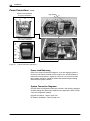
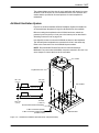
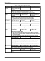
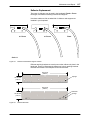
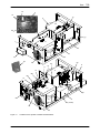
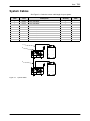
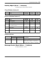
1
Coolwaver 2 610 UV Curing System Customer Product Manual Part 1105120-01 Issued 4/13 To order parts call 866-885-1212. For technical support call 800-524-1322. This document is subject to change without notice. Check http://emanuals.nordson.com/uvsystems for the latest version. NORDSON CORPORATION AMHERST, OHIO USA Address all correspondence to: Nordson UV Systems Inc. 555 Jackson Street Amherst, OH 44001 United States Tel:(800) 717-4228 Fax: (516) 213-8312 Email: [email protected] Website: www.nordsonuv.com Nordson Corporation welcomes requests for information, comments, and inquiries about its products. General information about Nordson can be found on the Internet using the following address: http://www.nordson.com. Trademarks Coolwave, Nordson, and the Nordson logo are registered trademarks of Nordson Corporation. Notice This is a Nordson Corporation publication which is protected by copyright. Original copyright date 2013. No part of this document may be photocopied, reproduced, or translated to another language without the prior written consent of Nordson Corporation. The information contained in this publication is subject to change without notice. DeviceNet is a trademark of ODVA, Inc. Part 1105120-01 E 2013 Nordson Corporation Table of Contents i Table of Contents E 2013 Nordson Corporation Safety . . . . . . . . . . . . . . . . . . . . . . . . . . . . . . . . . . . . . . . . . . . . . . . . . . Introduction . . . . . . . . . . . . . . . . . . . . . . . . . . . . . . . . . . . . . . . . . . . . . Qualified Personnel . . . . . . . . . . . . . . . . . . . . . . . . . . . . . . . . . . . . . . Intended Use . . . . . . . . . . . . . . . . . . . . . . . . . . . . . . . . . . . . . . . . . . . . Regulations and Approvals . . . . . . . . . . . . . . . . . . . . . . . . . . . . . . . . Personal Safety . . . . . . . . . . . . . . . . . . . . . . . . . . . . . . . . . . . . . . . . . . Ultraviolet Radiation . . . . . . . . . . . . . . . . . . . . . . . . . . . . . . . . . . . . . . First Aid . . . . . . . . . . . . . . . . . . . . . . . . . . . . . . . . . . . . . . . . . . . . . . Microwave Radiation . . . . . . . . . . . . . . . . . . . . . . . . . . . . . . . . . . . . . Radio Interference . . . . . . . . . . . . . . . . . . . . . . . . . . . . . . . . . . . . . . . Ozone . . . . . . . . . . . . . . . . . . . . . . . . . . . . . . . . . . . . . . . . . . . . . . . . . . High Temperatures . . . . . . . . . . . . . . . . . . . . . . . . . . . . . . . . . . . . . . . High Voltage . . . . . . . . . . . . . . . . . . . . . . . . . . . . . . . . . . . . . . . . . . . . Mercury Bulbs (Lamps) . . . . . . . . . . . . . . . . . . . . . . . . . . . . . . . . . . . UV-Curable Inks and Products . . . . . . . . . . . . . . . . . . . . . . . . . . . . . Fire Safety . . . . . . . . . . . . . . . . . . . . . . . . . . . . . . . . . . . . . . . . . . . . . . Action in the Event of a Malfunction . . . . . . . . . . . . . . . . . . . . . . . . Safety Precautions While Servicing . . . . . . . . . . . . . . . . . . . . . . . . . Control System Cleaning . . . . . . . . . . . . . . . . . . . . . . . . . . . . . . . High Voltage Connections . . . . . . . . . . . . . . . . . . . . . . . . . . . . . . Disposal . . . . . . . . . . . . . . . . . . . . . . . . . . . . . . . . . . . . . . . . . . . . . . . . Moving and Storage . . . . . . . . . . . . . . . . . . . . . . . . . . . . . . . . . . . . . . Safety Symbols . . . . . . . . . . . . . . . . . . . . . . . . . . . . . . . . . . . . . . . . . . 1-1 1-1 1-1 1-2 1-2 1-3 1-3 1-5 1-5 1-5 1-5 1-6 1-6 1-7 1-7 1-7 1-8 1-8 1-8 1-8 1-8 1-8 1-9 Description . . . . . . . . . . . . . . . . . . . . . . . . . . . . . . . . . . . . . . . . . . . . . Introduction . . . . . . . . . . . . . . . . . . . . . . . . . . . . . . . . . . . . . . . . . . . . . What is UV Curing? . . . . . . . . . . . . . . . . . . . . . . . . . . . . . . . . . . . . . . The UV Curing System . . . . . . . . . . . . . . . . . . . . . . . . . . . . . . . . . How Does it Work? . . . . . . . . . . . . . . . . . . . . . . . . . . . . . . . . . . . . System Components . . . . . . . . . . . . . . . . . . . . . . . . . . . . . . . . . . . . . Magnetron Operation and Life . . . . . . . . . . . . . . . . . . . . . . . . . . . . . Reflectors . . . . . . . . . . . . . . . . . . . . . . . . . . . . . . . . . . . . . . . . . . . . . . . 2.1 Inch Focus Reflector . . . . . . . . . . . . . . . . . . . . . . . . . . . . . . . . 3.1 Inch Focus Reflector . . . . . . . . . . . . . . . . . . . . . . . . . . . . . . . . Flood Reflector . . . . . . . . . . . . . . . . . . . . . . . . . . . . . . . . . . . . . . . . Options . . . . . . . . . . . . . . . . . . . . . . . . . . . . . . . . . . . . . . . . . . . . . . . . . 2-1 2-1 2-1 2-1 2-1 2-2 2-4 2-5 2-5 2-6 2-7 2-8 Part 1105120-01 ii Table of Contents Part 1105120-01 Installation . . . . . . . . . . . . . . . . . . . . . . . . . . . . . . . . . . . . . . . . . . . . . . Introduction . . . . . . . . . . . . . . . . . . . . . . . . . . . . . . . . . . . . . . . . . . . . . Inspection and Packaging . . . . . . . . . . . . . . . . . . . . . . . . . . . . . . . . . System Controller Installation . . . . . . . . . . . . . . . . . . . . . . . . . . . . . . Mounting Guidelines . . . . . . . . . . . . . . . . . . . . . . . . . . . . . . . . . . . Power Connections . . . . . . . . . . . . . . . . . . . . . . . . . . . . . . . . . . . . Power Load Balancing . . . . . . . . . . . . . . . . . . . . . . . . . . . . . . . System Connection Diagrams . . . . . . . . . . . . . . . . . . . . . . . . Network Connections . . . . . . . . . . . . . . . . . . . . . . . . . . . . . . . . . . Remote Inputs and Outputs . . . . . . . . . . . . . . . . . . . . . . . . . . . . . Machine Stop Interlock . . . . . . . . . . . . . . . . . . . . . . . . . . . . . . . Remote Power Level Control . . . . . . . . . . . . . . . . . . . . . . . . . Idle Mode . . . . . . . . . . . . . . . . . . . . . . . . . . . . . . . . . . . . . . . . . . Remote Standby and Lamp On . . . . . . . . . . . . . . . . . . . . . . . Quick Cycle Using Idle Mode . . . . . . . . . . . . . . . . . . . . . . . . . DeviceNet Installation . . . . . . . . . . . . . . . . . . . . . . . . . . . . . . . . . . Chassis Isolation . . . . . . . . . . . . . . . . . . . . . . . . . . . . . . . . . . . . BUS Power . . . . . . . . . . . . . . . . . . . . . . . . . . . . . . . . . . . . . . . . . Hardware Specifications . . . . . . . . . . . . . . . . . . . . . . . . . . . . . Software Specifications . . . . . . . . . . . . . . . . . . . . . . . . . . . . . . Lamphead Installation . . . . . . . . . . . . . . . . . . . . . . . . . . . . . . . . . . . . Mounting Guidelines . . . . . . . . . . . . . . . . . . . . . . . . . . . . . . . . . . . Optional Mounting Kit for Lampheads . . . . . . . . . . . . . . . . . . . . Light Shielding . . . . . . . . . . . . . . . . . . . . . . . . . . . . . . . . . . . . . . . . Cooling Air Installation . . . . . . . . . . . . . . . . . . . . . . . . . . . . . . . . . Internal Blower Lampheads . . . . . . . . . . . . . . . . . . . . . . . . . . External Blower Lampheads . . . . . . . . . . . . . . . . . . . . . . . . . . Exhaust Requirements . . . . . . . . . . . . . . . . . . . . . . . . . . . . . . . . . AirShield Ventilation System . . . . . . . . . . . . . . . . . . . . . . . . . . . . Monitoring Lamphead Air Pressure . . . . . . . . . . . . . . . . . . . . . . Top Pressure Port . . . . . . . . . . . . . . . . . . . . . . . . . . . . . . . . . . . Bottom Pressure Port . . . . . . . . . . . . . . . . . . . . . . . . . . . . . . . . Switching Pressure Ports . . . . . . . . . . . . . . . . . . . . . . . . . . . . . Lamphead Cable Connections . . . . . . . . . . . . . . . . . . . . . . . . . . RF Detector Installation . . . . . . . . . . . . . . . . . . . . . . . . . . . . . . . . . . . System Controller Configuration . . . . . . . . . . . . . . . . . . . . . . . . . . . 3-1 3-1 3-1 3-1 3-1 3-3 3-4 3-4 3-7 3-7 3-9 3-10 3-10 3-10 3-11 3-11 3-11 3-11 3-12 3-12 3-12 3-12 3-15 3-15 3-15 3-15 3-16 3-16 3-17 3-18 3-18 3-18 3-18 3-21 3-22 3-23 Operation . . . . . . . . . . . . . . . . . . . . . . . . . . . . . . . . . . . . . . . . . . . . . . . Introduction . . . . . . . . . . . . . . . . . . . . . . . . . . . . . . . . . . . . . . . . . . . . . Display and Controls . . . . . . . . . . . . . . . . . . . . . . . . . . . . . . . . . . . . . Additional Functions . . . . . . . . . . . . . . . . . . . . . . . . . . . . . . . . . . . Temperature . . . . . . . . . . . . . . . . . . . . . . . . . . . . . . . . . . . . . . . . Light Detector . . . . . . . . . . . . . . . . . . . . . . . . . . . . . . . . . . . . . . Starter Bulb Test . . . . . . . . . . . . . . . . . . . . . . . . . . . . . . . . . . . . Panel Lock . . . . . . . . . . . . . . . . . . . . . . . . . . . . . . . . . . . . . . . . . Operating Messages . . . . . . . . . . . . . . . . . . . . . . . . . . . . . . . . . . . . . Fault Messages . . . . . . . . . . . . . . . . . . . . . . . . . . . . . . . . . . . . . . . . . . Resetting Faults . . . . . . . . . . . . . . . . . . . . . . . . . . . . . . . . . . . . . . . System Timing Sequences . . . . . . . . . . . . . . . . . . . . . . . . . . . . . . . . Timing Sequence with Idle = Y . . . . . . . . . . . . . . . . . . . . . . . . . . Timing Sequence with Idle = N . . . . . . . . . . . . . . . . . . . . . . . . . . Correcting a Fault Condition . . . . . . . . . . . . . . . . . . . . . . . . . . . . Startup . . . . . . . . . . . . . . . . . . . . . . . . . . . . . . . . . . . . . . . . . . . . . . . . . Locally Operated Units . . . . . . . . . . . . . . . . . . . . . . . . . . . . . . . . . . Remotely Operated Units . . . . . . . . . . . . . . . . . . . . . . . . . . . . . . . Shutdown . . . . . . . . . . . . . . . . . . . . . . . . . . . . . . . . . . . . . . . . . . . . . . . 4-1 4-1 4-1 4-3 4-3 4-3 4-3 4-3 4-4 4-4 4-5 4-6 4-6 4-8 4-9 4-9 4-9 4-12 4-13 E 2013 Nordson Corporation Table of Contents E 2013 Nordson Corporation iii Troubleshooting . . . . . . . . . . . . . . . . . . . . . . . . . . . . . . . . . . . . . . . . . System Software Versions . . . . . . . . . . . . . . . . . . . . . . . . . . . . . . . . General Troubleshooting . . . . . . . . . . . . . . . . . . . . . . . . . . . . . . . . . . Fault Message Troubleshooting . . . . . . . . . . . . . . . . . . . . . . . . . . . . Bulb Troubleshooting . . . . . . . . . . . . . . . . . . . . . . . . . . . . . . . . . . . . . Curing Process Troubleshooting . . . . . . . . . . . . . . . . . . . . . . . . . . . General Lamphead Troubleshooting . . . . . . . . . . . . . . . . . . . . . . . . Diode Block Testing . . . . . . . . . . . . . . . . . . . . . . . . . . . . . . . . . . . . . . . 5-1 5-1 5-1 5-2 5-6 5-7 5-7 5-8 Maintenance and Repair . . . . . . . . . . . . . . . . . . . . . . . . . . . . . . . . . Introduction . . . . . . . . . . . . . . . . . . . . . . . . . . . . . . . . . . . . . . . . . . . . . Torque Specifications for System Fasteners . . . . . . . . . . . . . . . . . System Controller Maintenance and Repair . . . . . . . . . . . . . . . . . . Maintenance Schedule . . . . . . . . . . . . . . . . . . . . . . . . . . . . . . . . . System Controller Repair Procedures . . . . . . . . . . . . . . . . . . . . Preparation . . . . . . . . . . . . . . . . . . . . . . . . . . . . . . . . . . . . . . . . . Fuses . . . . . . . . . . . . . . . . . . . . . . . . . . . . . . . . . . . . . . . . . . . . . Cleaning System Controller Cooling Fans . . . . . . . . . . . . . . Lamphead Maintenance and Repair . . . . . . . . . . . . . . . . . . . . . . . . Internal Blower Lamphead Filter Replacement . . . . . . . . . . . . . Lamphead Repair Procedures . . . . . . . . . . . . . . . . . . . . . . . . . . . Preparation . . . . . . . . . . . . . . . . . . . . . . . . . . . . . . . . . . . . . . . . . Bulb Replacement . . . . . . . . . . . . . . . . . . . . . . . . . . . . . . . . . . . Reflector Replacement . . . . . . . . . . . . . . . . . . . . . . . . . . . . . . . Internal Blower Replacement . . . . . . . . . . . . . . . . . . . . . . . . . . . . Internal Blower Lamphead Complete Cover Removal . . . . . . Internal Blower Lamphead Cover Replacement . . . . . . . . . . . . External Blower Lamphead Cover Removal . . . . . . . . . . . . . . . Lamphead Internal Component Replacement . . . . . . . . . . . . . Preparation . . . . . . . . . . . . . . . . . . . . . . . . . . . . . . . . . . . . . . . . . Magnetron Replacement . . . . . . . . . . . . . . . . . . . . . . . . . . . . . Filament Transformer Replacement . . . . . . . . . . . . . . . . . . . Light Detector Board Replacement . . . . . . . . . . . . . . . . . . . . Temperature Sensor Replacement . . . . . . . . . . . . . . . . . . . . Starter Bulb Replacement . . . . . . . . . . . . . . . . . . . . . . . . . . . . Re-Assembly . . . . . . . . . . . . . . . . . . . . . . . . . . . . . . . . . . . . . . . . . 6-1 6-1 6-1 6-1 6-1 6-2 6-2 6-2 6-3 6-4 6-5 6-5 6-5 6-5 6-7 6-10 6-11 6-12 6-13 6-13 6-13 6-14 6-15 6-18 6-18 6-18 6-19 Parts . . . . . . . . . . . . . . . . . . . . . . . . . . . . . . . . . . . . . . . . . . . . . . . . . . . Introduction . . . . . . . . . . . . . . . . . . . . . . . . . . . . . . . . . . . . . . . . . . . . . CW2 610 System Controllers . . . . . . . . . . . . . . . . . . . . . . . . . . . . . . System Controller Repair Parts . . . . . . . . . . . . . . . . . . . . . . . . . . CW-2 Internal Blower Lampheads . . . . . . . . . . . . . . . . . . . . . . . . . . Torque Specifications for Lamphead Fasteners . . . . . . . . . . . . Parts Illustration − Internal Blower Lamphead Parts . . . . . . . . CW-2 External Blower Lampheads . . . . . . . . . . . . . . . . . . . . . . . . . Torque Specifications for Lamphead Fasteners . . . . . . . . . . . . Parts Illustration − External Blower Lamphead Parts . . . . . . . Bulbs . . . . . . . . . . . . . . . . . . . . . . . . . . . . . . . . . . . . . . . . . . . . . . . . . . . Reflector Conversion Kits . . . . . . . . . . . . . . . . . . . . . . . . . . . . . . . . . RF Detector . . . . . . . . . . . . . . . . . . . . . . . . . . . . . . . . . . . . . . . . . . . . . System Cables . . . . . . . . . . . . . . . . . . . . . . . . . . . . . . . . . . . . . . . . . . Accessories . . . . . . . . . . . . . . . . . . . . . . . . . . . . . . . . . . . . . . . . . . . . . Optional Lamphead Mounting Kit . . . . . . . . . . . . . . . . . . . . . . . . . . . Mounting Kit Installation . . . . . . . . . . . . . . . . . . . . . . . . . . . . . . . . 7-1 7-1 7-1 7-2 7-4 7-5 7-6 7-7 7-8 7-9 7-10 7-10 7-10 7-11 7-12 7-13 7-13 Part 1105120-01 iv Table of Contents Part 1105120-01 Specifications . . . . . . . . . . . . . . . . . . . . . . . . . . . . . . . . . . . . . . . . . . . System Controller . . . . . . . . . . . . . . . . . . . . . . . . . . . . . . . . . . . . . . . . Specifications . . . . . . . . . . . . . . . . . . . . . . . . . . . . . . . . . . . . . . . . . Current Draw . . . . . . . . . . . . . . . . . . . . . . . . . . . . . . . . . . . . . . . . . Light Output Settings . . . . . . . . . . . . . . . . . . . . . . . . . . . . . . . . . . . . . Master/Remote Power Setting Examples . . . . . . . . . . . . . . . . . Lamphead . . . . . . . . . . . . . . . . . . . . . . . . . . . . . . . . . . . . . . . . . . . . . . Bulb . . . . . . . . . . . . . . . . . . . . . . . . . . . . . . . . . . . . . . . . . . . . . . . . . . . . System Schematic . . . . . . . . . . . . . . . . . . . . . . . . . . . . . . . . . . . . . . . 8-1 8-1 8-1 8-2 8-3 8-3 8-4 8-4 8-4 UV Glossary . . . . . . . . . . . . . . . . . . . . . . . . . . . . . . . . . . . . . . . . . . . . 9-1 DeviceNet Specifications . . . . . . . . . . . . . . . . . . . . . . . . . . . . . . . . Introduction . . . . . . . . . . . . . . . . . . . . . . . . . . . . . . . . . . . . . . . . . . . . . Definitions . . . . . . . . . . . . . . . . . . . . . . . . . . . . . . . . . . . . . . . . . . . . Reference Documents . . . . . . . . . . . . . . . . . . . . . . . . . . . . . . . . . Governing Body . . . . . . . . . . . . . . . . . . . . . . . . . . . . . . . . . . . . . . . System Operation . . . . . . . . . . . . . . . . . . . . . . . . . . . . . . . . . . . . . . . . MAC ID / Baud Rate Configuration . . . . . . . . . . . . . . . . . . . . . . . LED Operation . . . . . . . . . . . . . . . . . . . . . . . . . . . . . . . . . . . . . . . . DeviceNet Interface . . . . . . . . . . . . . . . . . . . . . . . . . . . . . . . . . . . . . . Overview . . . . . . . . . . . . . . . . . . . . . . . . . . . . . . . . . . . . . . . . . . . . . Configuration . . . . . . . . . . . . . . . . . . . . . . . . . . . . . . . . . . . . . . . . . Initialization . . . . . . . . . . . . . . . . . . . . . . . . . . . . . . . . . . . . . . . . . . . Group 2 Only Slave Operation . . . . . . . . . . . . . . . . . . . . . . . . . . Certification . . . . . . . . . . . . . . . . . . . . . . . . . . . . . . . . . . . . . . . . . . . Identity Object (01HEX − 1 Instance) . . . . . . . . . . . . . . . . . . . . . . . Class Attributes (Instance 0) . . . . . . . . . . . . . . . . . . . . . . . . . . . . Instance Attributes (Instance 1) . . . . . . . . . . . . . . . . . . . . . . . . . . Common Services . . . . . . . . . . . . . . . . . . . . . . . . . . . . . . . . . . . . . Message Router Object (02HEX − 1 Instance) . . . . . . . . . . . . . . . DeviceNet Object (03HEX − 1 Instance) . . . . . . . . . . . . . . . . . . . . Class Attributes (Instance 0) . . . . . . . . . . . . . . . . . . . . . . . . . . . . Instance Attributes (Instance 1) . . . . . . . . . . . . . . . . . . . . . . . . . . Common Services . . . . . . . . . . . . . . . . . . . . . . . . . . . . . . . . . . . . . Assembly Object (04HEX – 2 Instances) . . . . . . . . . . . . . . . . . . . . Class Attributes (Instance 0) . . . . . . . . . . . . . . . . . . . . . . . . . . . . Instance Attributes (Instances 100 and 112) . . . . . . . . . . . . . . . Common Services . . . . . . . . . . . . . . . . . . . . . . . . . . . . . . . . . . . . . Connection Object (05HEX − 2 Instances) . . . . . . . . . . . . . . . . . . Class Attributes (Instance 0) . . . . . . . . . . . . . . . . . . . . . . . . . . . . Instance Attributes (Instances 1 − 2) . . . . . . . . . . . . . . . . . . . . . Common Services . . . . . . . . . . . . . . . . . . . . . . . . . . . . . . . . . . . . . S−Device Supervisor Object (30HEX − 1 Instance) . . . . . . . . . . . Class Attributes (Instance 0) . . . . . . . . . . . . . . . . . . . . . . . . . . . . Instance Attributes (Instance 1) . . . . . . . . . . . . . . . . . . . . . . . . . . Common Services . . . . . . . . . . . . . . . . . . . . . . . . . . . . . . . . . . . . . Exception Detail Alarm / Warning . . . . . . . . . . . . . . . . . . . . . . . . Lamp Object (64HEX − 16 Instances) . . . . . . . . . . . . . . . . . . . . . . Class Attributes (Instance 0) . . . . . . . . . . . . . . . . . . . . . . . . . . . . Instance Attributes (Instances 1−15) . . . . . . . . . . . . . . . . . . . . . Common Services . . . . . . . . . . . . . . . . . . . . . . . . . . . . . . . . . . . . . 10-1 10-1 10-1 10-1 10-1 10-2 10-2 10-3 10-4 10-4 10-4 10-4 10-4 10-4 10-5 10-5 10-5 10-5 10-5 10-6 10-6 10-6 10-6 10-7 10-7 10-7 10-10 10-11 10-11 10-11 10-12 10-12 10-12 10-12 10-13 10-14 10-15 10-15 10-16 10-16 Index . . . . . . . . . . . . . . . . . . . . . . . . . . . . . . . . . . . . . . . . . . . . . . . . . . . i E 2013 Nordson Corporation Safety 1-1 Section 1 Safety Introduction Read and follow these safety instructions. Task- and equipment-specific warnings, cautions, and instructions are included in equipment documentation where appropriate. Make sure all equipment documentation, including these instructions, is accessible to all persons operating or servicing equipment. All equipment is designed and manufactured to International Safety Standards to ensure that the health and safety of the operator is protected at all times. Figure 1-1 Microwave UV Warning Qualified Personnel Equipment owners are responsible for making sure that Nordson equipment is installed, operated, and serviced by qualified personnel. Qualified personnel are those employees or contractors who are trained to safely perform their assigned tasks. They are familiar with all relevant safety rules and regulations and are physically capable of performing their assigned tasks. E 2013 Nordson Corporation Part 1105120-01 1-2 Safety Intended Use Nordson ultraviolet (UV) equipment is intended specifically for integration into other machines and should NOT be operated as a standalone system or without appropriate safety guarding, shielding, and interlocks. It is the responsibility of the integrator and end user to ensure that the final assembly fulfills all necessary legislation and is completely safe before operation. This equipment is designed for the accelerated curing of UV inks, adhesives, and coatings. Do not use this equipment to cure alternative materials unless approved by the material supplier. The equipment is not flame or explosion proof and is not designed for use in hazardous areas. Use of Nordson equipment in ways other than those described in the documentation supplied with the equipment may result in injury to persons or damage to property. Some examples of unintended use of equipment include S S S S S S S using incompatible materials making unauthorized modifications removing or bypassing safety guards, shielding or interlocks using incompatible or damaged parts using unapproved auxiliary equipment operating equipment in excess of maximum ratings using equipment in hazardous areas Regulations and Approvals Make sure all equipment is rated and approved for the environment in which it is used. Any approvals obtained for Nordson equipment will be voided if instructions for installation, operation, and service are not followed. Part 1105120-01 E 2013 Nordson Corporation Safety 1-3 Personal Safety To prevent injury follow these instructions. S Do not operate or service equipment unless you are qualified. S Do not operate equipment unless safety guards, light shields, doors, and/or covers are intact and automatic interlocks are operating properly. Do not bypass or disarm any safety devices. S Keep clear of moving equipment. Before adjusting or servicing any moving equipment, shut off the system controller and wait until the equipment comes to a complete stop. Lock out power and secure the equipment to prevent unexpected movement. S Obtain and read Material Safety Data Sheets (MSDS) for all materials used. Follow the manufacturer’s instructions for safe handling and use of materials. Always use recommended personal protection devices. S Make sure the UV area is adequately ventilated. S The UV equipment runs at extremely high temperatures. Do not touch the UV lamphead face during operation or immediately after shutting off the equipment. S To prevent injury, be aware of less-obvious dangers in the workplace that often cannot be completely eliminated, such as hot surfaces, sharp edges, energized electrical circuits, and moving parts that cannot be enclosed or otherwise guarded for practical reasons. S Always wear safety glasses that offer UV protection. S Never expose any part of the body to direct or indirect UV light. Ultraviolet Radiation WARNING: Ultraviolet light is a form of electromagnetic radiation and can be harmful if exposure exceeds recommended levels. Protect eyes and skin from direct exposure to UV light. All equipment or areas where UV light is used must be adequately guarded, shielded, and interlocked to prevent accidental exposure. Ultraviolet light is not capable of penetrating into the body and interacting with internal tissues and organs. The National Institute for Occupational Safety and Health (NIOSH) document Criteria for Recommended Standard... Occupational Exposure to Ultraviolet Radiation (PB214 268) establishes guidelines for safe use. See Figure 1-2. Ultraviolet light is divided into wavelength bands A, B, C, and V along with vacuum UV. Although values for wavelength bands will vary depending on the source, the following ranges may be used as a guide. S UV-V (450−400 nanometers) – visible UV. S UV-A (400−315 nanometers) − represents the largest portion of UV energy and is most responsible for human skin aging and increased pigmentation. UV−A is at the lower limit of sensitivity to the human eye. S UV-B (315−280 nanometers) − most responsible for reddening and burning of the skin and damage to the eyes. S UV-C (280−100 nanometers) E 2013 Nordson Corporation Part 1105120-01 1-4 Safety Exposure to UV radiation can result in S reddening of skin S headaches S sore eyes ULTRA VIOLET X RAYS INFRA RED MICROWAVES RADIO WAVES VISIBLE 100 200 300 FAR UV VACUUM UV Figure 1-2 400 500 600 700 800 900 1000 nanometers NEAR UV U U UVC V UVA V V B Ultraviolet Light Wavelength Bands It is very important that all precautions are taken to prevent all UV light, whether direct or indirect, from escaping the curing area. Exposure to UV light can be harmful to both eyes and skin. Use the following table to determine the permissible exposure time to UV light on unprotected eyes or skin. Permissible Ultra Violet Exposures as Recommended by the American Conference of Government and Industrial Hygienists Part 1105120-01 Duration of Exposure (Per Day) Effective Irradiance (E Micro Watts/cm sq) 8 hours 0.1 4 hours 0.2 2 hours 0.4 1 hour 0.8 30 minutes 1.7 15 minutes 3.3 10 minutes 5.0 5 minutes 10 1 minute 50 30 seconds 100 10 seconds 300 1 second 3000 E 2013 Nordson Corporation Safety 1-5 First Aid Seek immediate medical attention for skin burns and direct UV exposure to the eyes. Microwave Radiation WARNING: The lamp system utilizes high powered RF microwave energy generated by a magnetron to provide power to the UV lamp. This technology is identical to that of residential microwave ovens and like these ovens can be dangerous if misused. The lamp system is safe provided that the RF screen and gasketing are intact. Any damage such as rips or holes in the screen may cause leakage of dangerous amounts of microwave radiation. The power to the lamp is interlocked to the RF detector and will shut down if microwave leakage exceeds safe levels. Any excessive leakage will cause the system to shutdown. Currently there are two organizations that set recommended guidelines for exposure to occupational microwave radiation exposure, OSHA (U.S. Department of labor, Occupational Safety and Health Administration − Directive 29cfr 1910.97) and ANSI (American National Standards Institute − Directive C95.1−1982). The ANSI directive, which is more stringent and most commonly referred to, states that individuals should not be exposed to microwave radiation levels above 8 mW/cm2 at 2.45 GHz on a continuous basis, or an average of 8 mW/cm2 over a six minute period. RF levels near the CoolWave 2 system installation should be checked periodically. To measure RF levels, a hand-held survey meter is available from ETS-Lindgren company. Their HI-1501 Survey Meter is calibrated for 2450 Mhz microwave sources and can measure RF levels from 0−2, 0−10, and 0−100 mW/cm2 More information can be obtained on the internet from http://www.ets−lindgren.com/. Radio Interference UV lamps are classified as non-consumer industrial, scientific, and medical (ISM) equipment, as defined in Federal Communications Commission (FCC) Rules and Regulations Volume 47, Part 18. As required by these rules, Nordson Corporation verifies that their systems are capable of compliance with applicable technical standards governing radiated emissions when the equipment is properly maintained and is installed in an appropriate light shield. This system complies with EN55011 (CISPR-1, Group 2, Class A). NOTE: Nordson UV lamps operate at a fundamental frequency of 2.45 GHz. They may cause interference with wireless local area networks (WLANs) that also operate at this frequency. Ozone Ozone (O3) is a colorless gas that is generated by the reaction of short-wave UV light (around 200−220 nanometers) with air, and it occurs whenever high-energy electrical discharge is present. E 2013 Nordson Corporation Part 1105120-01 1-6 Safety Ozone readily reverts to breathable oxygen when mixed with atmospheric air. Ozone should be removed from the UV source via a sealed duct and discharged to atmosphere according to local regulations. The discharge location should be away from pedestrian walkways and window openings and should be well above the average human breathing height for the area. Regular ozone checks should be carried out every three months using an ozone meter. Recommended levels of ozone in the atmosphere of a factory should not exceed 0.1 parts per million (PPM). This level is easily obtainable if factory recommended exhaust rates are followed. Ozone has a very distinct, strong odor even at low levels. Immediate ozone checks should be made if an operator can smell ozone. Most people can smell ozone at about one third the maximum allowable 0.1 PPM level. Ozone exposure will cause headaches and fatigue. It will also irritate the mouth and throat. Overexposure can lead to respiratory infections. If ozone is detected, 1. Shut down the UV system. 2. Check exhaust ducting for leaks. 3. Check the operator working area with an ozone meter. If a person is overcome by ozone, S Seek immediate medical assistance. S Move the individual to a warm uncontaminated atmosphere and loosen tight clothing at the neck and waist. S Keep the individual at rest. S If the person has difficulty breathing, oxygen may be administered provided that suitable apparatus and a trained operator are available. S If breathing is weak or has ceased, artificial respiration should be started. High Temperatures UV curing systems generally run at extremely high temperatures. A sudden shock from touching a high temperature surface might cause an operator to jump or take his attention away from other potential hazards. When shutting down UV equipment for maintenance, allow the equipment to cool before beginning work, or wear protective gloves and clothing to prevent burns. High Voltage The UV curing equipment operates at high voltages up to 5000 Vdc. If any electrical faults develop, the operator should: 1. Switch the equipment off immediately. 2. Make no attempt to service the equipment. 3. Call a qualified electrician trained to service this type of equipment. Part 1105120-01 E 2013 Nordson Corporation Safety 1-7 Mercury Bulbs (Lamps) The bulbs used in UV lamp systems contain mercury. Mercury is a toxic substance and must not be ingested or come into direct contact with the skin. Under normal UV operating conditions, mercury presents no hazard as it is completely contained in the sealed quartz tube of the bulb; however, it is strongly recommended that protective gloves and eye protection be worn when handling UV bulbs, and that a mercury spill kit be readily available. Mercury spill kits are commercially available from a number of sources. These precautions should be followed when disposing of UV bulbs: S Place the bulb in a rigid protective carton. S Dispose of used bulbs through a local mercury recycling center. S Wash your hands if a bulb breaks: mercury could come into contact with your skin. S Do not store or handle bulbs near food or beverages. Nordson Corporation will dispose of UV bulbs free of charge provided the customer covers all shipping costs associated with returning the bulbs. For bulb disposal, please clearly mark on the all bulb containers and shipping packages: BULBS FOR DISPOSAL ONLY. Bulbs should be shipped to: Primarc UV Technologies Bulb Disposal Department 2 Dan Forth Drive Easton, Pennsylvania 18045 UV-Curable Inks and Products Some materials used in UV curable inks, adhesives, and varnishes are toxic. Before handling them, read the Material Safety Data Sheets provided by the manufacturer, use the recommended personal safety equipment, and follow the recommended procedures for safe use and disposal. Fire Safety Under proper operating conditions, the surface temperature of the bulb is anywhere between 700−900 _C (1300−1700 _F), and the vapor gas inside the bulb is several thousand degrees Fahrenheit. Any form of flammable material (such as paper, lint, powder, or dirt) trapped under the lamp, within the lamp housing or in the lamp’s vicinity, will result in an increased risk of fire. To avoid a fire or explosion, follow these instructions. S Know where emergency stop buttons, shut-off valves, and fire extinguishers are located. S Clean, maintain, test, and repair equipment according to the instructions in this manual. Should a fire occur, the operator must de-energize the UV equipment immediately. E 2013 Nordson Corporation Part 1105120-01 1-8 Safety Action in the Event of a Malfunction If a system or any equipment in a system malfunctions, shut off the system immediately and perform the following steps: S Disconnect and lock out electrical power. S Identify the reason for the malfunction and correct it before restarting the equipment. Safety Precautions While Servicing A qualified competent electrician must carry out all electrical maintenance and servicing of this equipment. WARNING: This equipment operates at high voltages up to 5000 volts dc and is therefore potentially dangerous. The electrician servicing this equipment must take all precautions. WARNING: Isolate the equipment at the main, disconnect or lockout before removing any of the cover panels. Control System Cleaning Keep all contactors and relays clean and free from dirt and dust. Check them regularly. WARNING: This equipment is not rated for explosive environments. Do not install in extremely dusty or powder-charged work rooms. Contact your Nordson representative if in doubt. High Voltage Connections Check the high-voltage connections within the equipment carefully to make sure that these do not become dirty or coated with powder or other possible conducting material. Clean them regularly, at least whenever the lamp is changed, possibly more often where a particularly heavily polluted atmosphere occurs. Always make sure the unicable connectors are secure and tight before applying power. Disposal Dispose of equipment and materials used in operation and servicing according to local codes. Moving and Storage Moving or storing of the Nordson UV curing system must comply with all applicable local and state regulations. The lamphead and system controller should be shipped or stored in the original container or an equivalent and kept dry and clean at all times. Part 1105120-01 E 2013 Nordson Corporation Safety 1-9 All electrical power and other services must be disconnected and the lamphead must be cool before moving or storing this equipment. Remove the bulb from the lamphead before moving the lamphead. Store or ship the bulb in the original shipping tube. Due to the system controller’s weight, it is recommended a mechanical device be used for handling and they should be kept as low to the floor as possible. Controllers should be properly fastened to an appropriate fixture such as a pallet for handling and storing. Shipping of Nordson UV curing systems and their component parts must be done in accordance with all applicable shipping regulations including requirements for shipping of magnetic materials and mercury lamps. Safety Symbols The following safety symbols are used in this manual. The symbols are used along with warnings to help you operate and maintain your equipment safely. Pay attention to all warnings and follow directions to avoid personal injury. WARNING: Mechanical or combined mechanical/electrical hazards. WARNING: Electrical hazard. WARNING: UV, microwave, and RF radiation hazards. WARNING: Hot surface hazard. CAUTION: Equipment hazard. E 2013 Nordson Corporation Part 1105120-01 1-10 Safety Part 1105120-01 E 2013 Nordson Corporation Description 2-1 Section 2 Description Introduction This manual covers the Nordson CoolWave 2 610 Ultraviolet Microwave Curing System. It provides safety, installation, operation, and troubleshooting and repair information for the system and its components. What is UV Curing? Ultraviolet curing is achieved by a chemical reaction in special inks and coatings when intense UV energy is focused on them. Curing efficiency depends on UV power, coating weight, operation speed, type of substrates, material chemistry, and other factors. The UV Curing System The system is designed to cure UV inks, adhesives, and coatings for numerous industrial applications. The system consists of an individual 10-in. lamphead, a corresponding variable output system controller, a RF detector, and appropriate cables. Additional lampheads can be lined up end-to-end to form longer curing widths. How Does it Work? Inside the lamphead, a microwave generator (magnetron) operating at 2400 to 2500 MHz excites a 10-inch medium pressure UV bulb. Microwave energy from a magnetron is directed by a wave guide to the UV bulb. A screen located at the opening of the cavity allows the UV light emitted by the bulb to pass through while containing the microwave radiation. The wavelength of the emitted UV light is between 220 and 470 nanometers. Power output is 600 watts per inch. Light shielding is required to protect the operator and meet safety criteria. If shielding cannot fully contain the UV light, then the operator should be provided with protective equipment (refer to Safety in this manual). E 2013 Nordson Corporation Part 1105120-01 2-2 Description In addition to ultraviolet light, the UV bulbs radiate heat. A constant flow of cooling air through the lamphead is required to remove the excess heat and make sure that the bulbs, reflectors, and housings remain at an acceptable operating temperature. Two versions of the lamphead are available: with an internal blower, or with a duct connection to a customer-supplied external blower. The system controller supplies and controls the high voltage to the lamphead and provides a control circuit to interlock the lamphead with the curing machine. The unit is fitted with additional interlocks and safety features that prevent the operation of the system in an unsafe condition. The front panel of the controller displays operating and fault messages. System Components Table 2-1 and Figure 2-1 describe and illustrate the major components of a typical CoolWave ultraviolet microwave curing system. Your system may appear different depending on your application requirements. Table 2-1 System Components Item Component Description 1 Lamphead The lamphead consists of a bulb housing, UV bulb, starter bulb, reflectors, wave guide, magnetron and filament transformer assembly, and a circuit board incorporating a light detector, temperature sensor, and pressure sensor. The patented wave guide couples the magnetron output to the bulb. Lampheads are available in internal and external blower versions. 2 Ultraviolet Bulbs Use genuine Nordson replacement bulbs with this system. Alternative bulbs may damage the controls or overheat the reflector system. NOTE: The system warranty is void if genuine Nordson UV bulbs are not used. Contact a Nordson UV representative for ordering information. The system uses medium-pressure bulbs. The bulbs consist of high-purity quartz and have various fills to produce light at different wavelengths. Bulbs and controls are carefully matched to give optimum UV output and wavelength requirements. 3 Reflectors Refer to Reflectors on page 2-5 for more information. Reflectors can be ordered to suit the application. Focus reflectors are elliptical in shape to guide the UV light into a tight band across the surface of the material being cured. Flood reflectors produce a wider band of light. The reflectors are manufactured from glass with a proprietary coating to give maximum UV reflectivity while minimizing infrared radiation. 4 Starter Bulb Acts as the ignitor for the ultraviolet bulb. The starter bulb lights at the same time the magnetron is energized. After the UV bulb reaches full power the starter bulb turns off automatically. 5 Light Detector/Pressure /Temperature Board Monitors UV light and shuts the system down if the bulb fails to emit enough light. Includes a pressure transducer that monitors the lamphead cooling air pressure and shuts off system power if the cooling system fails to prevent a catastrophic lamphead failure. Monitors temperature inside the lamphead and shuts down the system if the internal temperature goes over the limit. Part 1105120-01 E 2013 Nordson Corporation Description Item Component 2-3 Description 6 Magnetrons The magnetrons are 3 KW, 2450 MHz generators that convert high voltage electrical inputs to RF energy. 6A Waveguide The wave guide directs the RF energy into the UV bulb, exciting a UV-emitting plasma within the bulb. 7A External Blowers 7B Internal Blower Forced air is used to cool the UV bulb and magnetrons. If external blowers are used, they must be sized appropriately to provide the required air flow. Contact Nordson UV engineering for external cooling air guidance. 8 Temperature Sensor Monitors the lamphead internal temperature. The sensor consists of a thermistor potted to a ring-tongue terminal and cable, which is connected to the light detector board. 9 System Controller Provides and controls high voltage to the lamphead magnetrons and controls other system functions. 10 RF Detector Detects leakage of microwave radiation. Will shut down system if radiation is detected. 8 1 5 6 2 9 6A 7A 4 3 7B 1 10 1 External Blower Lampheads (Mounted on Curing Machine) Figure 2-1 Internal Blower Lamphead System Components (Typical UV Curing System Setup) E 2013 Nordson Corporation Part 1105120-01 2-4 Description Magnetron Operation and Life Magnetrons consist of a cathode built into the center of a circular vacuum chamber, surrounded by permanent magnets. The chamber itself is the anode. Like a vacuum tube, a filament in the chamber is heated and bleeds off electrons which are attracted to the anode, the positive outer part of the chamber. This starts the magnetron. A high voltage power supply then apples a high negative potential to the anode, which accelerates the free electrons generated by the filament. A magnetic field parallel to the filament is imposed by the permanent magnets. The magnetic field causes the free electrons to spiral outward from the cathode in a circular path. Spaced around the rim of the chamber are cylindrical cavities open along their length and connected to the common cavity space. As electrons sweep past these openings, they induce a resonant, high-frequency electrical field in the cavity. A short antenna directs the high frequency (2.4 GHz) microwave energy into the waveguide which contains the energy and directs it to the UV bulb. Although magnetrons have no moving parts, they do eventually wear out and fail. The filament will slowly lose its ability to emit electrons to the point where the magnetron cannot start. The filament can fail open, or short to the anode. Magnetrons generate a lot of heat, and the heat can eventually cause the permanent magnets to lose energy and cause the magnetron to fail. Heat can also cause the ceramic antenna cap to crack and lose vacuum causing magnetron failure. An imbalance in the frequency output from the magnetrons can shorten their life as they then try to couple energy into one another. This typically causes the ceramic antenna cap to break, permanently damaging the magnetron. Part 1105120-01 E 2013 Nordson Corporation Description 2-5 Reflectors The reflectors are manufactured from borosilicate glass with a proprietary coating to provide maximum UV reflectivity while minimizing infrared radiation. Two types of reflectors are available for the lamphead: focus and flood. S The focus reflectors are available in 2.1 (53 mm) and 3.1 inch (79 mm) focal lengths. The focal point is measured from the bottom of the lamphead. See Figures 2-2 and 2-3. S The flood reflectors produce a wider band of UV light. See Figure 2-4. 2.1 Inch Focus Reflector Figure 2-2 2.1 Inch Focus Reflectors E 2013 Nordson Corporation Part 1105120-01 2-6 Description 3.1 Inch Focus Reflector Figure 2-3 3.1 Inch Focus Reflectors Part 1105120-01 E 2013 Nordson Corporation Description 2-7 Flood Reflector Figure 2-4 Flood Reflector Diagram E 2013 Nordson Corporation Part 1105120-01 2-8 Description Options Each CoolWave system lamp head can be fitted with optional patented components for maximum operating performance. AirShield Ventilation System: The modular patented AirShield ventilation system installs a high-quality quartz plate between the lamphead and the product to protect the product while maintaining cooling air flow through the lamphead. LightTite Shutter: Installed on the lamphead, the pneumatically powered proprietary Nordson LightTite shutter opens and closes instantly to block UV light without turning off the lamp head and system controller. The LightTite shutter is ideally suited for systems running manually loaded and unloaded parts, or heat-sensitive parts where accurate control of UV exposure is required. ThruCure Continuous Coating System: A hinged aluminum curing chamber equipped with customer-machinable entrance and exit vestibules and additional reflectors for a 360 degree cure that mounts on the lamphead. The ThruCure system can also be fitted with an optional nitrogen inerting system. Contact your Nordson representative for more information on these options. Standard Closed 90_ Open LightTite Shutter System Figure 2-5 AirShield Ventilation System ThruCure Chamber Lamphead Options Part 1105120-01 E 2013 Nordson Corporation Installation 3-1 Section 3 Installation WARNING: Allow only qualified personnel to perform the following tasks. Follow the safety instructions in this document and all other related documentation. Introduction This section contains information for installing the CoolWave 2 10-inch lamphead and system controller. Mounting and shielding are explained in general terms due to differences for each independent installation. Inspection and Packaging The Nordson CoolWave system has been carefully tested, inspected, and packaged prior to shipping. Upon receipt, inspect the shipping materials and components for visible damage. Report any damage immediately to the shipper and to your Nordson representative. NOTE: When opening the packaging, please take care so that the packaging can be re-used to ship the unit if necessary. Keep all packaging materials together and in a location where they will not get damaged. System Controller Installation Mounting Guidelines WARNING: Heavy equipment. Be careful when moving the system controller. Use approved lifting equipment or get help. Failure to observe this warning could result in personal injury or equipment damage. See Figure 3-1. S The system controller can be mounted on any stable horizontal surface. S Install the system controller so the operator panel and disconnect switch are easily accessible. S The blowers mounted on the front and the rear of the system controller and the exhaust vents on the sides must not be obstructed. E 2013 Nordson Corporation Part 1105120-01 3-2 Installation S Leave at least six inches of ventilation clearance on all four sides of the system controller. S If the system controller is mounted in an enclosure, there must be free and unobstructed ventilation from top to bottom and side to side within the enclosure. Contact your Nordson representative for enclosure cooling requirements. 453.50 [17.854] MPS2−610 NORDSON CORPORATION 555 JACKSON STREET AMHERST, OH 44001, USA Part No. Serial No. Frequency KVA 257.00 [10.118] 2 2 4 0 6 8 P RATE 5 P NET 2 1 0 Model Voltage 4 6 SYSTEM ON POWER SETPOINT STANDBY SYSTEM OFF POWER SETTING SET−SAVE LAMP HEAD MAGNETRON AIR PRESSURE 143.10 (5.64) 143.10 (5.64) NETWORK REMOTE LOCAL 25.40 [1.00] 790.50 [31.12] 158.19 [6.23] 753.00 [29.67] 25.25 [.99] ø28.50 [ø1.12] Sized for 3/4 in. Conduit 703.00 [27.70] Required Ventilation Clearance (All Four Sides) 152 mm (6 in.) Figure 3-1 System Controller Dimensions and Required Ventilation Clearance Part 1105120-01 E 2013 Nordson Corporation Installation 3-3 Power Connections NOTE: Power must be supplied from a dedicated source with a disconnect switch. See Figure 3-2. The customer power source must be wired in accordance with either the National Electric Code, Part I or the Canadian Electrical Code, Part I, or local codes. At a minimum, 10 AWG 600 volt wire is required unless superseded by local codes. Four #10−32 studs provide for line connection. Refer to the system controller ID plate for the input voltage and verify the transformer tap wiring using Tables 3-1 and 3-2. Measure the incoming power source voltage from the main power supply. Incoming voltage transients shall not exceed 150 volt amplitude and have a frequency content of less than 500 Hz. S The power line input is three phase (three wire with ground). S Refer to Table 3-1 for the T1 and T2 high-voltage transformers. Each has a terminal block with H1, H2, and H3 terminals. S Refer to Table 3-2 for the T3 control transformer. S All transformers must be wired for the same input voltage. Table 3-1 High Voltage Transformer Taps (T1 and T2) Input Voltage Range Transformer Tap 440−480 H1−H3 380−440 H1−H2 Table 3-2 Control Transformer Taps (T3) Input Voltage Transformer Tap 480 H1 and H4 400 H1 and H3 380 H1 and H2 Refer to Tables 8-2 and 8-3 in the Specifications section for current demand during normal full-power operation. Size supply wiring and circuit breakers or fuses to allow for heavy current draw during startup. To connect power to the system controller, remove the voltage cover on the back of the enclosure. Connect power wiring to the terminals labeled A (L1), B (L2), C (L3), and Ground. E 2013 Nordson Corporation Part 1105120-01 3-4 Installation Power Connections (contd) CW2-610 External Blower T3 Control Transformer 480V H4 400V H3 380V H2 0V H1 High Voltage T2 T1 CW2-610 Internal Blower T3 Control Transformer 0V H1 380V H2 400V H3 480V H4 Figure 3-2 System Controller Transformers Power Load Balancing Refer to the System Connection Diagrams. If you are supplying power to more than one system controller from a single source, shift the phases to balance the load as shown in Figures 3-4 and 3-5. If you have more than three system controllers, repeat the phase shift sequence again starting with the fourth system controller. System Connection Diagrams Only the network configuration settings are shown in the following diagrams. All other settings are optional and depend on the application. Refer to Table 3-6 for all configuration settings. Unicable Connection: Refer to page 3-21. RF Detector Installation: Refer to page 3-22. Part 1105120-01 E 2013 Nordson Corporation Installation 3-5 Lamphead Unicable RF Detector Input Power Source L1 L2 L3 RF Detector Cable Lamphead GND Network Settings Master: ID : 00 FLT: U NT: CAN or 485 CTRM: N L1 (A) L2 (B) L3 (C) GND System Controller Figure 3-3 System Connection Diagram − Stand Alone System Lamphead Unicable Input Power Source RF Detector Lamphead RF Detector Cable L1 L2 L3 GND Network Settings Master: ID : 00 FLT: A NT: CAN or 485 CTRM: Y First unit on network L1 (A) L2 (B) L3 (C) GND RJ45 Network Cable Lamphead Unicable Lamphead Network Settings Remote: ID : 01 FLT: A RFD: N NT: CAN or 485 CTRM: Y Last unit on network L2 (A) L3 (B) L1 (C) GND Figure 3-4 System Diagram − Two Systems, One RF Detector, One Network E 2013 Nordson Corporation Part 1105120-01 3-6 Installation Power Connections (contd) Lamphead Unicable Input Power Source L1 L2 L3 RF Detector RF Detector Cable Lamphead GND L1 (A) L2 (B) L3 (C) GND RJ45 Network Cable System Controller Lamphead Unicable Lamphead L2 (A) L3 (B) L2 (C) RJ45 Network Cable GND RJ45 Network Cable GND Lamphead Unicable Lamphead Network Settings Remote: ID : 02 FLT: A RFD: N NT: CAN or 485 CTRM: N System Controller Lamphead Unicable Lamphead L1 (A) L2 (B) L3 (C) Figure 3-5 Network Settings Remote: ID : 01 FLT: A RFD: N NT: CAN or 485 CTRM: N System Controller L3 (A) L1 (B) L2 (C) GND Network Settings Master: ID : 00 FLT: A NT: CAN or 485 CTRM: Y First unit on network Network Settings Remote: ID : 03 FLT: A RFD: N NT: CAN or 485 CTRM: Y Last unit on network System Controller System Diagram − Four Systems, Two RF Detectors, One Network Part 1105120-01 E 2013 Nordson Corporation Installation 3-7 Network Connections See Figures 3-3, 3-4, and 3-5. Up to 16 system controllers can be connected together with RJ-45 cables to form a network, which can then be operated from the master controller front panel or from a remote source. Master/Remote: When you configure the system controllers, you can set one unit (usually the first unit in the chain) as the Master, with the rest as Remotes. This is done through the ID configuration selection for each controller. The master is always configured as ID: 00; the Remotes as ID: 01.......15. Termination: The first and last units on the network must be terminated to prevent transmission line data errors. This is done through the CTRM configuration selection for each controller. CTRM: Y is terminated; CTRM: N is not terminated. Refer to System Controller Configuration on page 3-23 to make these settings. Remote Inputs and Outputs Refer to Figure 3-6 and Table 3-3. All inputs and outputs from the Remote I/O connector are normally open relay contacts and are rated for 24 Vdc. If you are using the PLC interface, refer to the DeviceNet specifications in Section 10 of this manual. RF DETECTOR MSTOP 16 RETURN 15 LAMP ON 14 COM 13 STDBY 12 COM 11 OFF/RESET 10 ADDRESS 0 AIN 5 4 SHLD 3 AOUT 2 ACOM 1 6 P 6 8 6 RATE 5 2 1 NETWORK REMOTE I/O E 2013 Nordson Corporation 0 7 ACOM 4 4 8 FAULT Figure 3-6 2 2 9 READY NOT USED PLC INTERFACE P NET MOD DEVICENET STATUS INDICATORS Remote I/O Connections Part 1105120-01 3-8 Installation Table 3-3 Remote Inputs and Outputs Connector Type Pin Input 16 Machine stop interlock (MSTOP) + 15 Machine stop interlock (RETURN) − 14 Lamp ON (LAMPON) 13 Lamp ON (COM) 12 Standby (STDBY) Input Input 11 Function Standby (COM) Description If this input is not interfaced to external equipment, a jumper must be installed across the pins. Opening this input turns off the lamp, sets the FAULT output, and causes the FAULT EXTERNAL INTERLOCK OPEN fault message to appear on the display. On I/O boards with the DeviceNet option this interlock can be configured for normal contact closure (Default setting) or isolated 24VDC. Refer to Machine Stop Interlock Jumper Setting on page 3-9. Remotely controls the system controller when operating in Remote mode. A pulse or momentary contact closure to this input turns the CoolWave lamphead on. (The Off/Reset contact must be closed.) The Off/Reset contact must be opened to turn the lamphead off. With Idle Mode Disabled (see IDLE in the System Controller Configuration section on page 3-25) − Controls the system controller when operating in Remote mode. A pulse or momentary contact closure to this input places the system in Standby mode. (The Off/Reset contact must be closed.) With Idle Mode Enabled from Lamp ON State− The first pulse or momentary contact closure to this input places the system in Idle Mode. A second pulse or momentary contact closure places the system in Standby mode. With Idle Mode Enabled from Lamp OFF State − A pulse or momentary contact closure to this input places the system in Standby mode. Note: Idle Mode can only be achieved from Lamp ON state. Input 10 Off/Reset Controls the system when operating in Remote mode. This contact must be closed for the lamphead to be turned on. Opening the contact turns the lamphead off and clears a fault condition. Use Pins 11 or 13 as Off/Reset (COM). Output 9 Ready 8 Ready Contact closes after the system controller is turned on and the light detector senses light output. In a networked system all system controllers must be turned on and all light detectors sense output. 7 Fault 6 Fault 5 Analog Input (AIN) + Remote Power Level Control Remotely varies the UV light output from 20% to 100% in 1% increments when the system is in Remote mode. This input can be configured for 4−20 mA or 0−10 Vdc. Refer to System Controller Configuration on page 3-24 for instructions. 4 Analog (ACOM) − Common Ground 3 Shield (SHLD) Earth ground Output 2 Analog Output (AOUT) Not used. Do not connect. 1 Analog Common (ACOM) Not used. Do not connect. Output Input Part 1105120-01 Contact closes whenever there is a fault present on the system. E 2013 Nordson Corporation Installation 3-9 Machine Stop Interlock CAUTION: Allow only qualified personnel to service the equipment. All power must be disconnected. Follow the safety instructions in this document and all other related documentation. The Machine Stop interlock (Remote I/O pins 15 and 16) can be configured for Normal or Isolated operation on I/O boards with the DeviceNet option by changing the J1 and J2 jumper positions on the Remote I/O circuit board. Jumper Position Pins Description Normal MSTOP (15, 16) Input compatible looking for contact closure only. This is the only interlock operation mode available on controllers without DeviceNet. Isolated (ISO) MSTOP (15, 16) External 24 Vdc @ 5 mA is required to maintain interlock contact closure. This is available only on controllers with DeviceNet. See Figure 3-7. To access the Machine Stop Interlock jumpers remove the system controller cover. The jumpers are on the back of the I/O connector circuit board. S The signal voltage range for the Isolated Machine Stop Interlock is 20−30 volts DC. S Both jumpers must be set to one of the two positions as shown in Figure 3-7. CAUTION: Any other jumper combination is invalid and will cause damage. NORMAL J2 J1 ISO J2 Figure 3-7 E 2013 Nordson Corporation J1 Machine Stop Interlock Jumper Settings − Shown Set To NORMAL Part 1105120-01 3-10 Installation Remote Power Level Control The Remote Power Level Control (AIN inputs 4 and 5) function adjusts the UV light output based on an external analog signal. This function must be enabled and configured for 4−20 mA or 0−10 Vdc. S Refer to Table 3-3 and Table 3-5 for connection and configuration instructions. S Refer to Table 4-4, step 5, in the Section 4, Operation for Power Level setting instructions. Idle Mode Idle Mode is a low power state used to quickly switch the lamp from curing power to an inactive, low light and heat state. Refer to Table 3-3 and Table 3-5 for connection and configuration instructions. The system must be in Lamp ON state to activate Idle Mode from the power control, the Remote I/O, or through the DeviceNet network. NOTE: The lamp should not remain in Idle Mode for longer than necessary. After 10 minutes in Idle Mode the lamp reverts to Standby mode. Table 3-4 Cycle Timing for Idle Mode Cycle Timing Idle to Lamp ON 3 seconds Lamp ON to Idle 2 seconds Remote Standby and Lamp On The Off/Reset contact (I/O 10, 13) must be closed for the unit to go to Standby or On mode. Once the lamphead is in Standby or On mode the lamphead remains in that mode until the Off/Reset contact is opened. Standard Startup: Use to go from off, through the warm-up sequence, to the SYSTEM ON mode. 1. On the host machine (or the master system controller), press the SYSTEM ON button. 2. The unit goes through the warm up cycle for 15 seconds before turning On. 3. After approximately 10 more seconds the unit has stabilized and is ready to run. The system ready output contact closes. Quick Startup: Use to go quickly from STANDBY mode to SYSTEM ON mode. 1. On the host machine (or master system controller), press the STANDBY button. Power is applied to the magnetron filament to prepare it for operation. 2. After approximately 15 seconds the magnetron filament is warmed up. The system goes into standby mode and remains there indefintely. Part 1105120-01 E 2013 Nordson Corporation Installation 3-11 NOTE: Do not leave the system controller in the standby mode for longer than 30 minutes. Prolonged standby periods shorten the magnetron life. 3. Press the SYSTEM ON button to turn on the UV lamp. The lamp turns on instantly but takes approximately 10 seconds to stabilize. After 10 seconds, the system ready output contact closes. Quick Cycle Using Idle Mode NOTE: IDLE configuration must be set to IDLE Y to enable Idle Mode. See IDLE in the System Controller Configuration table on page 3-25. 1. Begin by using the Standard or Quick Startup procedures on page 3-10 to achieve Lamp ON state. 2. Initiate Standby command (locally or remotely). 3. The unit immediately switches to Idle State (within 1 second). 4. To return to curing, initiate the Lamp ON command (locally or remotely). 5. The UV lamp turns on but full output is not available until the bulb has reached operating temperature, which takes approximately 5 seconds. This process can be repeated as required. DeviceNet Installation Chassis Isolation DeviceNet Drain to Chassis The drain wire is referenced to the chassis ground through one megohm resistance. V+ and V− to Chassis The DeviceNet power is not referenced to chassis ground with any impedance other than the stray capacitance due to the pc board layout. The board is designed to withstand +/− 500 volt test applied between the V+ and V− and the chassis. CAN_H and CAN_L to Chassis The circuit is designed to withstand the application of a +/− 500 volt test applied between these data lines and the chassis. CAN_H to CAN_L Isolation The CAN transceiver is fully compatible with the ISO 11898−24V specification. An un-powered node will not disturb the CAN bus lines. BUS Power BUS Sense Circuitry The system controller has an isolated physical layer. An optical isolator is used to monitor the BUS power, the loss of which results in an un-powered transceiver. Hot Plugging The system controller can be hot plugged into a DeviceNet network. Inrush current is limited to less than 500 milliamps for less than 50 microseconds. Mis-Wiring Protection The system controller supports mis-wiring protection as defined in the DeviceNet Specification (Section 10 of this manual). E 2013 Nordson Corporation Part 1105120-01 3-12 Installation Hardware Specifications The hardware design of the DeviceNet Interface follows ODVA recommendations. The interface can be found on the rear of the CoolWave2 system controller. Interface Connector Sealed micro connector is specified in ODVA specifications Volume 1, Release 2.0, Errata 2. Appendix C, table C.3. CoolWave2 uses a Phoenix connector. Indicators Red and green LEDs indicate the status of the module and the network. Node Address Switches Two 10-position rotary switches for setting the MAC ID. Data Rate Switch A 10-position rotary switch to set the data rate to 125, 250, or 500k Baud. Software Specifications Refer to Section 10 for the DeviceNet Interface Module specifications. Lamphead Installation The lamphead mounting must include provisions for UV light shielding and cooling air ductwork and venting. Each application has different constraints and therefore requires custom-designed enclosures and light shielding. Contact Nordson UV systems engineering department for help with designs. Mounting Guidelines Figures 3-9 and 3-10 provide the physical dimensions of the CoolWave 2 lampheads. See page 2-5 for focal lengths. Install lampheads with focus reflectors with the base positioned as follows: 2.1 focus reflectors: 3.1 focus reflectors: 53.3-mm (2.1-in.) above the substrate 78.8-mm (3.1-in.) above the substrate NOTE: Flood reflectors have no set distance. The base to substrate distance is not as critical and can be adjusted to vary the dosage and intensity. Lamphead 2.1 or 3.1 inches 53.3 or 78.8 mm Lamphead Base Substrate Figure 3-8 Part 1105120-01 Focus Reflector Lamphead Mounting E 2013 Nordson Corporation Installation 3-13 Inlet for 6-in. ID Duct 114.0 (4.488) 115 (4.53) Unicable Receptacle Top Pressure Port * 65.0 (2.559) 150.0 (5.906) 150 (5.906) Typ. 3 sides M5 Screws (Typ. 3 sides) 23.5 (0.925) 150 (5.906 435.9 (17.16) 370 (14.56) 115 (4.53) 53.3 (2.1 Focus) 78.8 (3.1 Focus) 266.4 (10.48) 199.2 (7.84) 9.50 (0.374) Bottom Pressure Port * 76.0 (2.992) 18.25 (0.719) 76.0 (2.992) 182.0 (7.165) All measurements in mm (in.) 76.0 (2.992) Bottom Pressure Port * * DO NOT BLOCK PRESSURE PORTS WHEN MOUNTING LAMPHEADS M4 Threaded Mounting Holes (8) Figure 3-9 Lamphead Dimensions − External Blower Version NOTE: Refer to page 3-18 for top and bottom pressure port usage. It is important that the pressure port being used to measure differential pressure not be blocked, and that the appropriate port be used depending on the cooling air and exhaust air arrangements. E 2013 Nordson Corporation Part 1105120-01 3-14 Installation 267.00 [10.512] 265.00 [10.433] DO NOT BLOCK FILTER 63.20 [2.488] 150 (5.906) 667.00 [26.260] Typ. 3 sides Unicable Receptacle 23.5 (0.925) Unicable Receptacle 150 (5.906 Front Pressure Port * 115.00 [4.528] 53.4 (2.1 Focus) 78.75 (3.1 Focus) Bottom Pressure Port * 200.96 [7.91] 9.50 (0.374) 76.0 (2.992) 18.25 (0.719) 76.0 (2.992) 76.0 (2.992) 182.0 (7.165) Bottom Pressure Port * All measurements in mm (in.) * DO NOT BLOCK PRESSURE PORTS WHEN MOUNTING LAMPHEADS M4 Threaded Mounting Holes (8) 133 (5.24) Figure 3-10 Lamphead Dimensions − Internal Blower Part 1105120-01 E 2013 Nordson Corporation Installation 3-15 Optional Mounting Kit for Lampheads An optional adjustable bracket, mounting plate, and screws are available as a kit for flexible mounting of lampheads. Refer to page 7-13 in Parts for the kit part number and mounting instructions. Adjustable Mounting Bracket Figure 3-11 Optional Adjustable Mounting Bracket Light Shielding Personnel in the area should be shielded from the UV light. S Provide adequate shielding of UV light. The lamphead must be enclosed so that no UV light is allowed to escape. S Any louvered material used for exhaust must be a light-shielding design. S If UV light does escape the operator must wear approved UV-protective clothing and eyewear. Cooling Air Installation Internal Blower Lampheads Internal blower lampheads do not require a cooling air source. However, the flow of cooling air must not be restricted or impeded, either at the inlet or the outlet. If an AirShield ventilation system or any type of exhaust-restricting devices are used, the exhaust air must be evacuated to ensure adequate cooling air flow. Refer to the AirShield Ventilation System instructions on page 3-17. E 2013 Nordson Corporation Part 1105120-01 3-16 Installation External Blower Lampheads For lampheads without internal blowers, the customer must supply cooling air through ductwork to each lamphead. The duct connection is for 6-in. ID ducts. If you plan on using variable speed external blowers, contact Nordson UV engineering for advice on the design of the air handling system. The following specifications must be maintained for all applications at all times or the life of the lamphead will be greatly reduced with the possibility of failure: S Unimpeded and unrestricted flow of cooling air through the lamphead. S Constant static pressure of 7-in. water column measured from the inside of the lamphead to atmosphere. S 350+25% CFM of filtered airflow through the lamphead. It is important to size the cooling air blower to provide at least an additional 25% of cooling air measured at the duct inlet just prior to the lamphead. Size the blower to accommodate all losses in the ducts and ensure that the specified air flow and pressure are delivered to the lamphead. NOTE: Recommended Flexible Duct Hose for External Lamphead cooling air: McMaster-Carr part number 55125K26, neoprene coated 6-in ID hose. Use worm clamps to connect the hose to the lamphead. In many applications cooling air is provided to multiple lampheads from a common source. In these installations it is recommended that air flow adjustment dampers such as the Fantech IR-6 iris damper be added to the ducting as close to the lamphead as possible, within 0.5 meters (1.6 ft), for proper air flow balancing. Once the system is up and running, check the pressure inside the lamphead by pressing the LAMPHEAD − AIR PRESSURE button on the face of the system controller. Refer to Operation for startup procedures. Exhaust Requirements Lamphead cooling air must be exhausted when lampheads are enclosed in a cure chamber or when the air flow is restricted and/or captured at the lamphead face. When lampheads are installed in a cure chamber and the lamphead cooling air is exhausted to the open air within the chamber you must size the chamber exhaust system to evacuate at least 125% of the air flow into the lampheads. You must also factor in the capacity to remove all air in the chamber including air flow into the chamber through all openings, doors, conveyors, and cracks. The air flow required is the sum of all the lampheads and openings and must be at a static pressure great enough to keep a negative pressure in the chamber. When an AirShield Ventilation system, quartz plate, or any other device restricts the lamphead exhaust air flow, the exhaust system must evacuate at least 125% of the air flow into the lamphead at a static pressure that ensures that there is an even flow or a slight negative pressure at the lamp face. Part 1105120-01 E 2013 Nordson Corporation Installation 3-17 The exhaust blower and duct size for each application will depend on many variables. Size all blowers to accommodate all losses in the ductwork and ensure that the specified air flow and pressure for each lamphead is maintained. AirShield Ventilation System Figure 3-12 shows a standard AirShield Ventilation System kit installed on an external blower lamphead. A high flow AirShield kit is also available. Before mounting the lamphead on the AirShield enclosure, switch the pressure hose from the top or front port to the bottom port as described in Switching Pressure Ports on page 3-18. Use eight M4 screws to mount the AirShield enclosure to the lamphead. The internal blower lampheads are mounted to the kits in the same way. Refer to the Parts section for the AirShield kit part numbers. NOTE: Recommended Flexible Duct Hose for exhaust extraction: McMaster-Carr part number 55125K26, neoprene coated 6-in ID hose. Use worm clamps to connect the hose to the vent stubs. 6-in. Intake Top Pressure Port 48.1 mm (1.894 in.) 38.1 mm (1.5 in.) 6-in. Exhaust High Flow Kit Standard Kit 35.4 mm (1.394 in.) 25.4 mm (1.0 in.) Port for Bottom Pressure Reading 8−M4 x 35 Screws (Std Kit) 8−M4 x 50 Screws (High Flow Kit) (included in kits) Quartz Plate Figure 3-12 AirShield Kit Installation (External Blower Lamphead Shown) E 2013 Nordson Corporation Part 1105120-01 3-18 Installation Monitoring Lamphead Air Pressure See Figures 3-13 and 3-14. The lamphead pressure sensor on the light detector board is connected by a hose to atmosphere at the top/front or bottom pressure port. (See Figures 3-9 and Figure 3-10 for the location of the pressure ports on internal and external blower versions.) The hose must be connected to Port B on the board, as shown. It is important that the pressure port not be blocked, and that the appropriate port be used depending on the cooling air and exhaust air arrangements. Top Pressure Port (Factory default.) If the exhaust air from the lamphead is not restricted in any way the top pressure port should be used. Examples of this type of installation are when lamps are mounted in a large enclosure. Caution should be used when using the top pressure port as any restriction of the exhaust air will influence the pressure sensor readings and possibly damage the lamphead. Bottom Pressure Port In applications where there is a restriction preventing the free flow of exhaust air from the lamphead, the bottom pressure port must be used. Examples of this type of application are quartz light shields, AirShield ventilation systems, dedicated exhaust ducts, or any other type of exhaust box or lamp face attachment that can restrict the exhaust air flow. When using the bottom pressure port the lamphead mounting structure must be designed so that this port is open to the air exiting through the screen. Do not simply set the lamp in a bracket or on a ledge that could cover over the bottom pressure port. Switching Pressure Ports External blower lampheads are shipped with the pressure transducer connected to the top port. Internal blower lampheads are shipped with the transducer connected to the front port. Use this procedure to switch the hose connection from the top or front port to the bottom: 1. See Figures 3-13 and 3-14. Remove the lamphead cover. 2. Disconnect the pressure hose and unscrew the barbed fitting from the top or front pressure port. 3. Install the barbed fitting in the bottom pressure port, then feed the hose through the lamphead and connect it to the barbed fitting. Part 1105120-01 E 2013 Nordson Corporation Installation 3-19 Top Pressure Port (Factory Connection) Port B Hose Connection Hose Barbed Fitting Bottom Pressure Port Figure 3-13 Pressure Port Connections − External Blower Version E 2013 Nordson Corporation Part 1105120-01 3-20 Installation Port B Hose Connection Front Pressure Port (Factory Connection) Hose Bottom Pressure Port Barbed Fitting Figure 3-14 Pressure Port Connections − Internal Blower Version Part 1105120-01 E 2013 Nordson Corporation Installation 3-21 Lamphead Cable Connections CAUTION: The unicable conducts high and low voltage between the system controller and the lamphead. It is important that the unicable connectors be completely engaged and tightened before turning on the UV system. Failure to properly engage these connectors can result in severe damage to the system components. Before inserting the plug into the receptacle check both and ensure that the pins are not bent, and that the rubber inserts are in good condition and not damaged. Make sure also that there is no evidence of arcing or other damage on the pins and sockets. See Figures 3-3 and 3-15. Connect the unicable to the system controller and the lamphead. NOTE: The unicable plugs are keyed and can only be inserted into the receptacles when correctly oriented. Do not force the plugs into the receptacles. Do not use the screw rings to pull the plugs into the receptacles. In most cases, it might help to wiggle the plug slightly while pushing it into the receptacle to ensure that all the pins mate securely with the sockets. Push the plug into the receptacle as far as it will go, then start threading the screw ring onto the threaded portion of the receptacle. Continue to push on and wiggle the plug while tightening the screw ring until the plug is firmly seated into the receptacle. When fully mated, the red indicator on the plug should not be visible and there should be no movement between the plug and the receptacle. NOTE: When tightening the screw ring, it is recommended to use a 30−32 DIN1810B hook wrench (spanner wrench) to insure that the connection is secure. There are four holes in the screw ring for the wrench pin. Red Indicator: Incorrectly Installed No Red Indicator: Correctly Installed 30−32 DIN1810B Spanner Wrench (Customer-Supplied) Figure 3-15 Unicable Connection E 2013 Nordson Corporation Part 1105120-01 3-22 Installation RF Detector Installation See Figures 3-3 and 3-6 for RF Detector connections and Figure 3-16 for dimensions. S The RF detector shuts down the system controller when the RF level detected is above the calibrated trip level. This can happen if the lamphead RF screen is torn or incorrectly installed. S One RF detector is normally required for every 16 networked units within one curing enclosure. However, some applications and systems may require a RF detector on each unit. Contact your Nordson representative for more information. S Do not mount the RF detector directly below the lamphead. S The RF detector can be damaged by excessive heat and extreme RF fields. Do not install it less than 8 inches from the lamphead. S Mount the RF detector so that the antenna faces the lampheads and is between the operator and the lampheads or the lampheads and any opening (the major source for RF leakage). S The detector has a patented self test feature to make sure it is working properly. The detector is not serviceable. If it fails, fault code 26 appears on the system controller. Replace the RF detector if it fails. 19.1 (0.75) Ø7.2 (Ø0.28) Antenna 88.9 (3.50) Ø4.0 (Ø0.16) 12.7 (0.50) 38.1 (1.50) 14.0 (0.55) 42.8 (1.69) 203 (8) 203 (8) No RF Detector No RF Detector 203 (8) No RF Detector 305 (12) Figure 3-16 Part 1105120-01 All dimensions are in mm (in.) RF Detector Installation E 2013 Nordson Corporation Installation 3-23 System Controller Configuration Once the system controller and lamphead are mounted and all connections made, the last step is to configure the controller for your application, using the front panel display, keys, and configuration menus. NOTE: The system controller power must be on and the lamphead must be OFF to enter the configuration menus. Press the SYSTEM OFF button to turn the lamphead off if LAMPON is displayed. Use these keys to configure the system controller: Key Function Nordson Logo (behind the letter “d”) Press for 5−15 seconds to enter the configuration menu. SET−SAVE Set choice and advance to next configuration setting. UP/DOWN Scroll through setting choices. UP DOWN MPS2-610V OFF SET/SAVE NORDSON LOGO Figure 3-17 System Controller Front Panel 1. Move the front power switch to the ON position. The system goes through a power-up test sequence, then displays the installed software version numbers, then displays OFF. 2. Press the Nordson Logo for 5−15 seconds to enter the configuration menu. The configuration settings are displayed in the order listed in Table 3-5. 3. Press the UP or DOWN keys to scroll through the choices available for each setting. Press the SET−SAVE key to save the displayed choice and advance to the next setting. 4. The last display is PWROFF. Turn the power supply power switch to the OFF position to set the configuration in flash memory. NOTE: The only configuration setting not done through the system software is the Remote I/O Machine Stop Interlock function. Refer to page 3-9 for this setting. E 2013 Nordson Corporation Part 1105120-01 3-24 Installation Table 3-5 Power Supply Configuration Settings Display ID 00..15 (Unit ID) Function Unit ID: Sets unit ID for network, identifies master or remote. Configuration 1 Master = ID 00 Configuration 2 Remotes = ID 01..15 For a standalone system controller, set the unit ID to 00. For networked power supplies, set the master to 00 and set the remotes to 01, 02.....15. S Each system controller on a network must have a unique ID number. FLT (Fault) Fault State: Sets Unit Fault to fault units separately or all together. FLT U = FAULT UNIT (Fault this unit only) FLT A = FAULT ALL (Shuts down all units on the network). This setting is for multiple system master/remote networks. A networked system controller in a fault condition can fault just itself or the entire network. S All networked system controllers must have the same fault setting. RFD (RF Detector) Sets RF detector status for each system controller. RFD Y = RF Detector connected RFD N = No RF detector connected A Master controller is automatically set to RFD Yes. Remote power supplies can be set to Yes or No. Only one RF detector is required for a network. NT (Network) Specifies network communication protocol. NT CAN = CAN BUS protocol NT 485 = 485 protocol The CAN BUS protocol is the preferred protocol for system controller networks. It must be selected for any network using DeviceNet. S All system controllers on the network must be set to the same protocol. CTRM Can termination CTRM Y = CAN termination Yes. CTRM N = CAN termination No. Internal network termination setting. S Set to Yes for networked controllers that have only one network port connected (and so are on one end of the network). The Master system controller is typically on one end of the network. S Set to No for all networked controllers that have both network ports connected. ANA Remote Power Level Control enable/setting ANA Y = Y (yes) ANA N = N (no) Refer to Table 3-3 on page 3-8 for connections. S If set to ANA Y, then the next setting allows you to choose the input. In Remote mode, light output is controlled by the input to the AIN and ACOM terminals (5 and 4). S If set to ANA N, then the light output is controlled from the system controller front panel in both Remote and Local modes. IN Analog input selector mA = 4−20 mA control V = 0−10 Vdc control Specifies the input type for Remote Power Level Control. This selection appears if ANA Y is selected. Refer to Table 3-3 on page 3-8 for connections. CTL Remote control source IO = Use discrete remote I/O terminal DN = Use DeviceNet for remote control Refer to Table 3-3 on page 3-8 for discrete remote I/O connections. IO is the default setting. Part 1105120-01 E 2013 Nordson Corporation Installation Display PCTL Function Power control algorithm Configuration 1 Y = Enable Power Control mode 3-25 Configuration 2 N = Use current control mode (default) If set to PCTL Y, the power control algorithm controls the total power output to reduce the variation of power over the life of the magnetron. PCTL N is the default and preferred method of control (current control). LAN Language in which faults are displayed ENG=English FR=French IT=Italian GE=German SP=Spanish Use this setting to choose the language for fault messages. English is the default language. IDLE Enabling IDLE mode allows a return to Lamp ON mode within 3 seconds (use the Standby command for activation). This is done by operating the lamp system at a low power, which is not capable of curing, with minimal heat on substrate. IDLE N=No Not enabled IDLE Y=Yes Operation of IDLE mode (local or remote) through Standby control. Refer to the Operation Section for the proper sequence. VSPD Lampheads with an internal blower may incorporate variable speed control to provide consistent bulb temperature. VSPD N=No Set to N if lamphead is not equipped with internal blower VSPD Y=Yes Enables speed control Set to Y only if an internal blower lamphead is used. PWROFF POWER OFF No selection No selection This is a message instructing you to turn the power supply switch OFF to save your settings in flash memory. E 2013 Nordson Corporation Part 1105120-01 3-26 Installation Part 1105120-01 E 2013 Nordson Corporation Operation 4-1 Section 4 Operation WARNING: Allow only qualified personnel to perform the following tasks. Follow the safety instructions in this document and all other related documentation. Introduction Startup procedures will vary depending on how the UV system is integrated into other systems and equipment. The startup procedures documented in this manual are strictly for the UV equipment. Display and Controls See Figure 4-1 and Table 4-1. 3 2 4 1 MPS2-610V 10 9 8 7 6 5 Figure 4-1 11 CoolWave 2 System Controller Displays and Controls E 2013 Nordson Corporation Part 1105120-01 4-2 Operation Table 4-1 CoolWave 2 Displays and Controls Item Control Description 1 Main Power Switch Turns system power on and off. 2 SYSTEM ON Turns the lamphead on when STDBY, IDLE, or OFF is displayed. From OFF, the system goes into WARMUP mode until the filament is warmed up, then power is applied to the magnetrons and LMPDLY is displayed while the magnetrons stabilize. LAMPON is displayed when the lamp lights. 3 STANDBY When the Standby button is pressed power is removed from the lamp. The magnetron filaments remain powered. STDBY is displayed. This mode allows the system to cycle to curing power faster than from OFF. Excessive use of Standby mode will shorten magnetron life. IDLE (if enabled) If the Idle mode is enabled during system configuration, then pressing the Standby button puts the system in Idle mode. In this mode, the lamp is powered at a low light and heat state. When SYSTEM ON is pressed, the lamp will cycle to LMPDLY then to LAMPON. The lamp should not remain in Idle Mode for longer than necessary. After 10 minutes in Idle Mode the lamp automatically reverts to Standby mode. 4 SYSTEM OFF Turns the lamphead off. 5 NETWORK LOCAL REMOTE Sets system operation to LOCAL mode (system controlled from front panel) or to REMOTE mode (system controlled by a remote device or controller through discrete I/O or DeviceNet). 6 LAMPHEAD AIR PRESSURE Displays lamphead pressure in X.X inches w.c. (water column). 7 LAMPHEAD MAGNETRON Displays the current through each magnetron in milliamps (mA). Pressing the MAGNETRON button toggles between MAG A and MAG B current. If the power control mode is configured, then OPC is displayed. 8 POWER SETTING Adjusts the UV output of the lamp, as a percentage of full power. Power can be adjusted from 20% to 100% while the lamp is in the OFF or ON state. At 100% the lamp produces the maximum UV intensity it is capable of (600 watts/inch). The system is factory set to operate at 100% output. To check the power level set point, press the SET-SAVE button. In network LOCAL mode, you can change the output in 5% increments by pressing the UP or DOWN buttons. Press the SET-SAVE button in order to save your changes and return to normal operation. In network REMOTE mode, power can be adjusted in 1% increments by a remote PLC. Regardless of the control method, changes to the power setting take effect immediately. Remote Units Controlled by a Master: The remote units determine their power setting by multiplying the master power setting by the remote set point (set at the front panel of the remote unit). If the Master power setting is 80%, then the output of a remote unit set at 50% is actually 40% of its potential output (80% x 0.5 = 40%). Part 1105120-01 S S The remote unit set point is always the value set from its front panel. S All systems can only be set to values between 20% and 100%. If any of the above cases calculate a value below 20% the control will stay at 40% until the calculated value is again above 20%. This will not set an error but the unit power will not go below 20%. The Master set point is set from its front panel when it is in Local mode. In Remote mode it can be set by analog input or DeviceNet. E 2013 Nordson Corporation Operation Item Control 4-3 Description 9 Digital Display Displays power levels, operation and fault messages. 10 POWER SETPOINT When pressed, displays the current power setpoint. 11 Nordson Logo (System Configuration) Accesses system controller configuration. Refer to Table 3-4 in the Installation section for more information. Additional Functions Temperature To display the internal temperatures of the lamphead and system controller press the OFF and SET-SAVE buttons simultaneously: LH xxC = Lamphead Internal Temperature LB xxC = Lamphead Circuit Board Temperature MB xxC = System Controller Control Board Temperature Light Detector To test the light detector and check UV output, press the DOWN button and STANDBY buttons simultaneously. You can do this on controller power up to watch the UV output come up to full power. Sensor Saturation = 900−960 counts Normal Operation = 920−950 counts Acceptable Operation = greater than 700 counts Alarm Trip Point for 50% to 100% Power Level = 600 counts Alarm Trip Point for less than 50% Power Level = 300 counts Starter Bulb Test To test the starter bulb, turn OFF the lamp, press the LOCAL button for approximately 20 seconds, and check for light output. The starter bulb turns on for a few seconds during lamp ignition, to help the UV bulb ignite. Panel Lock NOTE: For use with systems operated in remote modes. To lock out all front panel control functions, press REMOTE for approximately 20 seconds. LOCK is displayed momentarily. The period at the left of the display remains on as long as the system is locked. To unlock the system press REMOTE for approximately 20 seconds. UNLOCK displays and the unit returns to normal operation. E 2013 Nordson Corporation Part 1105120-01 4-4 Operation Operating Messages Table 4-2 lists the messages that indicate operating status. Table 4-2 Display Messages Message Description OFF The system controller power is On. The lamphead is in the Off state. WARMUP The magnetron filament is energized. This message is only displayed during filament warm-up (about 15 seconds). STDBY The filament is warm and the unit is waiting for an On command. LMPDLY Lamp Delay Lamp ON has been enabled. The power contactor is closed, and high voltage has been applied to the magnetrons. This message is displayed during lamp warm-up (about 10 seconds). LAMPON Lamp is On at the set power level. L COOL Lamp Cool Down Lamp was On and a Standby command has been received. The magnetron power is shut off. This message is displayed during lamp cool down (about 20 seconds). The lamphead then goes to a standby state. The unit will not restart until the lamp cool down is complete. C DLY Cool Down Delay An Off command was received. The lamphead power is turned off. The message is displayed during lamp cool down (about 60 seconds). The unit will not restart until the lamp cool down is complete. IDLE Lamp is idling at 10% of full power. Fault Messages When a fault is detected, the system controller shuts down the high voltage, turns on the FAULT relay output, and displays a fault message. Table 4-3 lists the fault messages. Refer to Section 5, Troubleshooting, for fault correction procedures. Table 4-3 Fault Messages No. Fault Message Description 0 NETWORK CONFIG Duplicate system IDs on the network. 2 FILAMENT FUSE BLOWN There is no current detected on the filament transformer circuit when the system controller is turned on. 3 HIGH CURRENT ON MAG High current exceeding 950 mA has been detected on the magnetron high-voltage circuit. 4 CURRENT IMBALANCE The magnetrons are turned on (LAMPON) and the magnetron currents differ by more than 100 ma for a period exceeding about 600 ms. 5 ON NETWORK UNIT There is a fault on a remote unit. 6 MAG POWER WHEN OFF Magnetron current sensed in standby mode. 7 NO LIGHT DETECTED There was insufficient output from the lamp when the system controller energized the magnetrons in the Lamp On mode. 9 HARDWARE FAILURE The system controller is not communicating with the light board. Part 1105120-01 E 2013 Nordson Corporation Operation No. Fault Message 4-5 Description 10 DEVICENET ERROR There is a DeviceNet communication fault. 11 DEVICENET HARDWARE FAIL There is no communication with the DeviceNet processor. 12 MAG VOLTAGE ERROR The magnetron voltage is not within limits. 13 NETWORK COMM ERROR The control board can no longer communicate with a previously detected system. 15 POWER CONTROL AT LIMIT The power control cannot control the output within 5% of the setpoint. 16 LOW LAMPHEAD PRESSURE There is insufficient or no air pressure in the lamphead. 17 EXT INTERLOCK OPEN The external machine stop interlock is open or is not at 24 Vdc, depending on the jumper setting. 18 POWER UNIT OVER TEMP The system controller is over temperature. 19 RF DETECTOR MISSING The RF detector is not connected. 20 RF DETECTOR TRIPPED The RF detector has detected a high RF field. 22 LAMPHEAD OVER TEMP Lamphead temperature sensor is over temperature. Transformer thermal switch(es) open. May be caused by insufficient air flow through system controller cabinet. 23 HV CABLE UNPLUGGED The system controller is not communicating with the lamphead. The high-voltage cable from the system controller to the lamphead is disconnected or damaged. 24 LOW CURRENT ON MAG The magnetron is below 5 mA minimum current value. 25 PHASE CONTROL AT LIMIT The system controller cannot regulate to the power setpoint. 26 RF DETECTOR FAILED The RF detector is defective and must be replaced. 27 PHASE CONTROLLER ERROR The system control is not communicating with the phase board. 28 MAG FILAMENT IS OPEN One of the two magnetron filaments has failed. Resetting Faults Operating in Local Mode: Press the Off button to reset a fault once it has been corrected. Operating in Remote Mode: Open and close the Reset contact to reset a fault once it has been corrected. NOTE: Once the fault has been corrected you can reset a fault on a unit operating in Remote Mode from the host controlling the master unit through either a discrete I/O or DeviceNet. E 2013 Nordson Corporation Part 1105120-01 4-6 Operation System Timing Sequences NOTE: Refer to Section 5, Troubleshooting if the system fails during startup. Timing Sequence with Idle = Y (Also see Table 3-5) Powering ON the System Controller Total Seconds 12 seconds Turn on main disconnect switch on front panel. Controller goes through initial boot sequence with a full display test. When complete, controller displays OFF. Changing system status from OFF to LAMP ON Total Seconds 25 seconds Press SYSTEM ON button. Display reads WARMUP. Display reads LMPDLY. Display reads LAMPON. Changing system status from LAMP ON to IDLE Total Seconds ~ 1 second Press STANDBY button Once. Display reads IDLE. NOTE: The controller automatically switches to Standby after 10 minutes in Idle mode. Idle is a configurable mode. If not enabled, only the Standby mode is active. Changing system status from IDLE to LAMP ON Total Seconds ~ 2 seconds Part 1105120-01 Display reads IDLE. Press SYSTEM ON button. Display reads LMPDLY. Display reads LAMPON. E 2013 Nordson Corporation Operation 4-7 Changing system status from LAMP ON to STANDBY Total Seconds 20 seconds Display reads LAMPON. Press STANDBY button Twice. Display reads IDLE followed by L COOL. Display reads STDBY. NOTE: If Idle is not enabled, pressing the Standby button Once switches the controller to Standby mode. Changing system status from STANDBY to LAMP ON Total Seconds 10 seconds Display reads STDBY. Press SYSTEM ON button. Display reads LMPDLY. Display reads LAMPON. Changing system status from LAMP ON to OFF Total Seconds 60 seconds E 2013 Nordson Corporation Display reads LAMPON. Press SYSTEM OFF button. Display reads C DELY. Display reads OFF. Shutdown timing at completion of process allows for proper cooling. Part 1105120-01 4-8 Operation Timing Sequence with Idle = N (Also see Table 3-5) Powering ON the System Controller Total Seconds 12 seconds Turn on main disconnect switch on front panel. Controller goes through initial boot sequence with a full display test. When complete, controller displays OFF. Changing system status from OFF to LAMP ON Total Seconds 25 seconds Press SYSTEM ON button. Display reads WARMUP. Display reads LMPDLY. Display reads LAMPON. Changing system status from LAMP ON to STANDBY Total Seconds 20 seconds Display reads LAMPON. Press STANDBY button Once. Display reads L COOL. Display reads STDBY. Changing system status from STANDBY to LAMP ON Total Seconds 10 seconds Display reads STDBY. Press SYSTEM ON button. Display reads LMPDLY. Display reads LAMPON. Changing system status from LAMP ON to OFF Total Seconds 60 seconds Part 1105120-01 Display reads LAMPON. Press SYSTEM OFF button. Display reads C DELY. Display reads OFF. Shutdown timing at completion of process allows for proper cooling. E 2013 Nordson Corporation Operation 4-9 Correcting a Fault Condition Correcting a fault condition Total Seconds Max 60 seconds 25 seconds Display reads fault condition (message scrolls). Correct the reason for the fault, then push SYSTEM OFF button. Display reads C DELY. Press SYSTEM ON button. Display reads WARMUP. Display reads LMPDLY. Display reads LAMPON. Startup Locally Operated Units Table 4-4 Startup Procedures for Locally Operated Units Step Single Unit Operated Locally Multiple Units Networked to a Master Unit Operated Locally 1 Switch system electrical power ON. 2 Turn the main power switch on the front of the system controller unit to the ON position. After a brief power-up test sequence, OFF appears on the display. 3 Make sure that all interlocked access doors are closed and that external cooling and exhaust fans are running if not directly connected to the system controller blower contacts. If external interlocks are wired and open, FAULT EXT INTERLOCK will be displayed. 4 On the NETWORK selector, press LOCAL. Set the NETWORK configuration. S On the master unit NETWORK selector, press LOCAL. S On the remote unit NETWORK Selectors, press REMOTE. Continued... E 2013 Nordson Corporation Part 1105120-01 4-10 Operation Step 5 Single Unit Operated Locally Multiple Units Networked to a Master Unit Operated Locally Set the POWER SETTING. Set the POWER SETTING. 1. Press the SET-SAVE button on the POWER SETTING selector until the power level is displayed. 1. On the master unit, press the SET-SAVE button on the POWER SETTING selector until the power level is displayed. 2. Press the UP or DOWN arrows to set the desired power level. The power level changes immediately. 2. Press the UP or DOWN arrows to set the desired power level. 3. Press the SET-SAVE button to save the setting and exit the power setting function. NOTE: The power level can be changed at any time during operation with the lamp ON or OFF. 3. Press the SET-SAVE button to save the setting. 4. Set the POWER SETTING at each remote unit between 20 and 100 using the same procedure as the master unit. Each remote POWER SETTING can be different. The actual power output of each remote is dependent on the Master POWER SETTING. For example, if your master unit POWER SETTING is 80 and your first remote unit POWER SETTING is 50, the actual output of the first remote unit will be 0.5 x 0.8 or 40%. NOTE: In most cases, remote units should be set to 100%. 6 External Blower Units: Turn on the external blower. If there is insufficient pressure the system faults and FAULT LOW LAMPHEAD PRESSURE is displayed. (Check for proper pressure with the appropriate instrumentation.) The internal blower automatically turns on and off as required. Continued... Part 1105120-01 E 2013 Nordson Corporation Operation Step 7 Single Unit Operated Locally 4-11 Multiple Units Networked to a Master Unit Operated Locally Press SYSTEM ON to start the lampheads. LAMPON is displayed when the lamphead is ready to cure. Standard Startup − Preferred Method Use this procedure to go directly through the warm-up to the LAMPON mode. 1. On the single unit or master unit, press SYSTEM ON. WARMUP will appear on the display. The magnetron filaments are warmed up for 15 seconds. 2. LMPDLY now displays while lamphead takes approximately 10 seconds to stabilize. 3. LAMPON appears in the display and the system is ready to run. Or Quick Startup from Standby Mode NOTE: Excessive use of the standby mode will shorten magnetron life. This method should only be used when a quick startup is required. Use this procedure to put the system in Standby mode before moving to the SYSTEM ON mode. 1. On the single unit or master control unit, press the STANDBY button. WARMUP appears on the display for approximately 15 seconds, then STDBY appears. NOTE: Do not leave the system controller in the standby mode for longer than 30 minutes. Prolonged standby periods shorten magnetron life. 2. Press the SYSTEM ON button to turn on the lamps. LMPDLY appears for approximately 10 seconds while the lamphead stabilizes, then LAMPON appears. Quick Cycle Using Idle Mode NOTE: IDLE mode must be enabled. See IDLE in the System Controller Configuration table on page 3-25. 1. Use the Standard or Rapid startup procedures to achieve LAMPON state. 2. Initiate Standby command (locally or remotely). 3. The unit will immediately switch to Idle State (achieved in 1 seconds). 4. To return to curing, initiate LAMPON command (locally or remotely). 5. The lamp is ready to cure within approximately 5−7 seconds. NOTE: After 10 minutes in Idle mode, the unit automatically switches to Standby mode. E 2013 Nordson Corporation Part 1105120-01 4-12 Operation Remotely Operated Units NOTE: The system can be wired to initiate lamphead start from either the process machine or from the UV system controller. The system controller I/O and a simple panel can be used to control the UV system. Or, if the DeviceNet protocol is used, the UV system can be fully automated to work in concert with a complete production system. Table 4-5 Startup Procedures for Remotely Operated Units Step Single Unit and Units Networked to a Master Unit Operated Remotely 1 Switch the electrical disconnect to ON. 2 Turn the main power switch on the front of the system controller to the ON position. After a brief power-up test sequence, OFF appears on the display. 3 Make sure that all interlocked access doors are closed and that the exhaust fan is running. If external interlocks are wired and open, the fault message FAULT EXT INTERLOCK appears in the display. 4 On the front panel under NETWORK, press REMOTE. NOTE: For networked units, press REMOTE on each unit. 5 Set the POWER SETTING. See Table 4-1 item number 8 on page 4-2. 6 Turn on the external blowers. If there is insufficient pressure a system fault occurs and the message FAULT LOW LAMPHEAD PRESSURE appears in the display. (Check for proper pressure.) The internal blower automatically turns on and off as required. Part 1105120-01 E 2013 Nordson Corporation Operation 4-13 Shutdown CAUTION: Do not shut off the system with the main power switch while the lamps are operating. Bulbs and magnetrons can and will be damaged. The lamp turns off if any of the following conditions occur: Normal Shutdown S SYSTEM OFF button on the system controller is pressed. S REMOTE OFF command through discrete I/O or DeviceNet. Fault Shutdown S Cooling air for the lamphead ceases or is insufficient. S Any of the safety interlocks wired into the UV equipment are interrupted. These include exhaust fan, access panels, doors and process equipment. S Any fault condition occurs. Table 4-6 Shutdown Procedures Step Shutting Down Systems Locally Shutting Down Systems Remotely 1 Press the SYSTEM OFF button. Press the SYSTEM OFF button on the remote or host machine. 2 External Blower units: Allow the lampheads at least 60 seconds of cool down time before shutting off the cooling air. On units with internal blowers, the system shuts off the blower when the internal temperature falls to a safe level. External Blower units: Allow the lampheads at least 60 seconds of cool down time before shutting off the cooling air. Typically the external blowers are controlled by the remote or host machine. On units with internal blowers, the system shuts off the blower when the internal temperature falls to a safe level. CAUTION: Failure to provide cool down time can cause problems restarting the lamps as well as greatly reduce the life of the lamphead bulbs. CAUTION: Failure to provide cool down time can cause problems restarting the lamps as well as greatly reduce the life of the lamphead bulbs. 3 Turn off main power to all units. E 2013 Nordson Corporation Part 1105120-01 4-14 Operation Part 1105120-01 E 2013 Nordson Corporation Troubleshooting 5-1 Section 5 Troubleshooting WARNING: Allow only qualified personnel to perform the following tasks. Follow the safety instructions in this document and all other related documentation. These troubleshooting procedures cover only the most common problems. If you cannot solve a problem with the information given here, contact your local Nordson representative for help or call 800−524−1322 for technical support. System Software Versions If you call for technical support, you may be asked to provide the version numbers for the software installed in your system. During power up, the system controller displays the software versions for the following components, in this order: V DXXX = Display Board V MXXX = Main Control Board Microprocessor V PXXX = Phase Board Microprocessor V IXXX = Main Control Board CAN Interface V LXXX = Light Detector Board (Lamphead) V OXXX = I/O Board to DeviceNet NOTE: V OXXX only present for systems using DeviceNet. General Troubleshooting Use the charts on the following pages to troubleshoot your system. NOTE: If a system controller does not start up, disconnect power to the controller, then remove the cover and check the fuses. Refer to page 6-2 in Section 6, Maintenance and Repair for fuse locations. E 2013 Nordson Corporation Part 1105120-01 5-2 Troubleshooting Fault Message Troubleshooting Problem Possible Cause Corrective Action Incorrect controller ID setting, two or more controllers with same ID. Reconfigure ID settings so that each controller has a unique ID number. Refer to System Controller Configuration beginning on page 3-23. Filament transformer fuse F4 on main control board blown. Excessive power line noise. Refer to Power Line Connections on page 3-3. Open in filament control circuit to transformer. Verify proper continuity within system controller and lamphead. See Figure 8-1, System Schematic. Magnetron has failed. Replace the magnetrons. Short in unicable cable. Inspect the unicable for shorts. Short in the lamphead. Inspect the high voltage white and black cables from the unicable receptacle to the magnetrons for shorts. Fault 4: FAULT CURRENT IMBALANCE End of magnetron life. Replace the magnetrons. Magnetron current imbalance. The current level of magnetron A and B differs by more than 100 mA. Improper magnetron wiring. Verify the magnetron wiring connections. See Figure 8-1, System Schematic. Fault 5: FAULT ON NETWORK UNIT Fault has occurred on remote system controller. Correct fault on remote system controller. Phase control board has failed. Replace phase control board. Fault 0: FAULT NETWORK CONFIGURATION Network detecting multiple units with same ID. Fault 2: FAULT FILAMENT FUSE BLOWN Open filament transformer circuit. No filament current. Fault 3: FAULT HIGH CURRENT ON MAG High current on high-voltage circuit. Current exceeds limit. Fault on remote unit. Fault 6: FAULT MAG POWER WHEN OFF Phase control board failure Magnetron current detected when in Standby or Off mode. Continued... Part 1105120-01 E 2013 Nordson Corporation Troubleshooting Problem Fault 7: FAULT NO LIGHT DETECTED Lamp Fault The light detector does not sense sufficient light output. Fault 9: FAULT HARDWARE FAILURE Possible Cause 5-3 Corrective Action Bulb has failed. Replace the bulb. Light sensor D1 on light detector board blocked. Refer to page 4-3 to check the light output seen by the sensor. Clean the sensor on with isopropyl alcohol, or replace the board. Light sensor D1 has degraded, or light detector board failed. Replace the light detector board. The recommended replacement interval is 10,000 hours of operation. Refer to page 6-18 in Section 5, Maintenance and Repair. Magnetrons are approaching end of life. Replace magnetrons. Main control board has failed. Replace main control board. DeviceNet is not properly configured. Review DeviceNet software specification and reconfigure. Controller hardware failure. Replace the I/O board or main control board, or replace the ribbon cables. Arcing or opens in the high voltage circuit. Check the high voltage wiring, from the inside of the controller to the magnetrons. Failed diode block in system controller. Test diode block as described on page 5-8. Replace diode block if failed. Magnetrons have failed. Check the high voltage wiring, from the inside of the controller to the magnetrons. Replace the magnetrons. Remote controllers not powered or connected to network. Turn on remote controllers, check connections. Damaged network cables. Replace the network cables. Improper network setup. Refer to Network Connections and System Controller Configuration in Section 3, Installation. Control board failure Main controller not communicating with lamphead interface chip. Fault 10: FAULT DeviceNet ERROR DeviceNet Error. DeviceNet communications failure. Fault 11: FAULT DEVNET HARDWARE DeviceNet Hardware Error. Communication between main control board and I/O board is lost. Fault 12: FAULT MAG VOLTAGE ERROR Magnetron voltage error. Magnetron voltage maximum exceeded or the difference between the magnetrons is too great. Fault 13: FAULT NETWORK COMM Network Fault Master/remote network connection lost. Continued... E 2013 Nordson Corporation Part 1105120-01 5-4 Troubleshooting Problem Fault 15: FAULT POWER CTRL AT LIMIT Possible Cause Corrective Action Magnetrons have failed. Replace the magnetrons. Low voltage to magnetrons. Transformer taps set incorrectly. Check transformer in system controller. Fault 16: FAULT LOW LAMPHEAD PRESSURE External blower is off. Turn external blower on. Internal blower failure. Check blower wiring, transformer, fuse. Replace blower if necessary. Pressure Fault Lamphead air pressure is below setpoint at selected power setting. Air flow through lamphead is restricted. Remove any restrictions in lamphead air flow. Large pressure drop in external blower ducting. Correct restrictions in external blower ductwork. Ducts must be sized properly with minimum bends to supply proper air pressure. If low pressure faults persist, consider mounting the blower closer to the lamphead, increasing the duct size, or increasing the blower size. Pressure hose connected to wrong port. Check port connection. Refer to page 3-18 for instructions. Pressure port is blocked. Unblock the pressure port. Damaged pressure hose. Check hose and replace if necessary. Open external interlock. Check all system interlocks and the MSTOP connection. There must be continuity between Pins 15 and 16 on the rear panel Remote I/O connector. I/O jumpers are set incorrectly (DeviceNet capable system). Verify that the jumper position matches the interlock method. Make sure 24Vdc is available to interlock circuit. 24Vdc not being supplied to interlock. Check voltage and correct if necessary. Fault 18: FAULT POWER UNIT OVER TEMP System controller cooling fans are restricted or not operating. Remove fan restrictions or replace the fans. Make sure fans are rotating in the correct direction. System controller temperature is over 65 _C. Ambient temperature is above specification. Reduce the ambient temperature to 5−40 _C (41−104 _F). Fault 19: FAULT RF DETECTOR MISSING RF detector is not properly connected. Check the RF detector connections. RF cable is damaged. Check the continuity of the RF cable. Replace the cable if necessary. See Figure 8-1, System Schematic. RF detector is damaged. Replace the RF detector. Power control at limit. System controller is unable to regulate output. Fault 17: FAULT EXT INTERLOCK Interlock Fault MSTOP I/O open or under voltage. RF Fault. System does not sense the RF detector. Continued... Part 1105120-01 E 2013 Nordson Corporation Troubleshooting Problem Fault 20: FAULT RF DETECTOR TRIP Possible Cause 5-5 Corrective Action RF Detector is detecting a high level of RF Make sure the RF screen is not missing, loose, or damaged. Incorrect RF detector mounting location. Refer to page 3-22 for mounting requirements. Cooling air is being restricted. Make sure air flow through lamphead is not restricted. Refer to Corrective Actions for Fault 16. Fault 23: FAULT HV CABLE UNPLUGGED Unicable not connected or damaged. Check unicable connections and continuity. See Figures 8-1 and 8-2, System Schematics. System controller not communicating with lamphead. Light detector board in lamphead unplugged or failed. Check the internal connections to the light detector board. Replace board if all connections are good. Fault 24: FAULT LOW CURRENT ON MAGS Open HV circuit to magnetrons. Check black and white high-voltage cables to magnetrons. Wiring to magnetrons not connected properly. Verify wiring connections. HV transformer taps set incorrectly in system controller. Refer to the Transformer Tap Table on page 3-3 to verify settings. Failed diode block in system controller. Test diode block as described on page 5-8. Replace diode block if failed. Magnetrons at end of life. Replace magnetrons. Failed contactor. Replace contactors. Failed diode block (open diode) in system controller. Test diode block as described on page 5-8. Replace diode block if failed. Damaged main control board (defective relay #1). Replace main control board. HV transformer taps set incorrectly. Refer to the Transformer Tap Table on page 3-3 to verify settings. Phase control board failed. Replace phase control board. Fault 26: FAULT RF DETECTOR FAILED RF detector self test fails or detector has been permanently damaged by a very high RF field. Replace RF detector. Refer to RF Detector Installation on page 3-22. RF Fault. RF Detector failed self-test. NOTE: This failure is only possible under extreme conditions. RF Fault. High RF field detected. Fault 22: FAULT LAMPHEAD OVER TEMP Lamphead temp is over 95 _ C. Magnetron Current Fault Magnetron current cannot be maintained. Fault 25: FAULT PHASE CTRL AT LIMIT Phase control at limit. System controller is unable to regulate the system to the specified output level. Continued... E 2013 Nordson Corporation Part 1105120-01 5-6 Troubleshooting Problem Fault 27: FAULT PHASE CONTROLLER ERROR Possible Cause Corrective Action Phase control board failure. Replace phase control board. Magnetron has failed. Replace magnetrons. Control does not detect the phase board. Fault 28: FAULT MAG FILAMENT IS OPEN Low filament current. Bulb Troubleshooting NOTE: Any bulb that has been touched with bare hands or otherwise contaminated should be cleaned with isopropyl alcohol prior to use. Clean latex or nitrile gloves must be worn when handling bulbs. Failure to keep bulbs clean may result in premature failure. Problem Possible Cause Corrective Action 1. Bulbs have white fingerprints Dirt and oils on the bulb were burned in while the bulb was operating. Replace the bulb. Wear clean latex or nitrile gloves whenever handling bulbs. 2. Bulb does not start Bulb is damaged or system controller has faulted. Check the system controller for fault messages. Replace the bulb. 3. Bulb is rippled Bulb is overheating. Clean all air filters. Check the lamphead pressure by pressing the LAMPHEAD AIR PRESSURE button. Make sure the proper bulb for the lamp is installed. 4. Bulb has a white or gray cloudy appearance End of bulb life. Replace the bulb. Bulb is overheating. If UV output is below acceptable levels, check the system cooling then replace the bulb if necessary. Make sure the proper bulb for the lamp is installed. 5. Bulb does not fit securely in lamphead Bulb mounting tips are chipped or broken. Replace the bulb. 6. Bulb is overheating Reflectors not properly installed. Check reflectors and install correctly if necessary. Refer to page 6-7 in the Section 6, Maintenance and Repair for installation instructions. Replace the reflectors if necessary. Wrong bulb used. Make sure the proper bulb for the lamp is installed. Part 1105120-01 E 2013 Nordson Corporation Troubleshooting 5-7 Curing Process Troubleshooting Problem Possible Cause Corrective Action System running correctly but material not curing Reflectors are installed incorrectly. Check reflectors; make sure they are installed correctly in the brackets and supports. Reflectors are dirty or damaged. Clean or replace the reflectors. RF screen dirty. Replace the RF screen. Lamp not in focus. Focus the lamphead. Incorrect bulb type. Replace with the correct bulb type. Low power level setting. Increase the power level on the system controller. Material issue. Contact the material supplier to verify the UV spectrum/intensity output. General Lamphead Troubleshooting Problem Low lamphead pressure Possible Cause Corrective Action Refer to Fault Message Troubleshooting in this section. Magnetron failure RF fault on system controller The lamphead is showing signs of electrical arcing E 2013 Nordson Corporation Tear in the RF screen in front of the bulb. Replace the screen. RF screen not securely fastened. Tighten the screen. Lamphead bulb has failed. Replace the lamphead bulb. RF detector was improperly installed. Check RF placement and connections to system controller. Refer to the Section 3, Installation for installation requirements. Loose component or debris in the lamphead. Tighten all fasteners. Clean the lamphead interior. Refer to Section 6, Maintenance and Repair to replace any damaged lamphead parts. Part 1105120-01 5-8 Troubleshooting Diode Block Testing WARNING: Shut off power to the system controller, allow the capacitors time to bleed off voltage, then remove the diode blocks from the controller before performing the following tests. Failure to observe this warning can result in equipment damage or personal injury. There are two diode blocks in the system controller. Each diode block contains 4 high voltage rated diodes connected in a bridge network. Diode 1 Connection: HV− and AC-1 (Anode to HV−, Cathode to AC-1) Diode 2 Connection: HV− and AC-2 (Anode to HV−, Cathode to AC-2) Diode 3 Connection: AC-2 and C (Anode to AC2, Cathode to C) Diode 4 Connection: C and AC-1 (Anode to AC1, Cathode to C) TP− GND Pin 1 TP+ FB C AC-2 AC-1 HV− Figure 5-1 Diode Block Terminals and Connector Pins Tests: GND to pin 1 GND to pin 2 GND to pin 3 GND to pin 4 GND to pin 5 GND to pin 6 GND to pin 7 GND to pin 8 GND to pin 9 GND to pin 10 TP− to pin 2 TP− to TP+ C to FB C to GND Part 1105120-01 1005 ohm 1% short, less than 0.2 ohm 20,000 ohm 1% short, less than 0.2 ohm open, over 20 M ohm open, over 20 M ohm open, over 20 M ohm open, over 20 M ohm open, over 20 M ohm open, over 20 M ohm short, less than 0.2 ohm 200 ohm 1% 1000 ohm 1% 4.9 ohm 1% E 2013 Nordson Corporation Maintenance and Repair 6-1 Section 6 Maintenance and Repair WARNING: Allow only qualified personnel to perform the following tasks. Follow the safety instructions in this document and all other related documentation. Introduction Establish acceptable curing levels for your process and then develop a maintenance schedule that fits your needs. Radiometers can be used to measure relative readings for spectral output as a means of monitoring spectral intensity. The maintenance and replacement schedule for the system will depend upon your: S S S S application process. plant environment. quality of cooling air passing through the system. coating formulation. Torque Specifications for System Fasteners Torque specifications for controller and lamphead fasteners are contained in tables following the controller and lamphead parts lists in the Parts section. They are identified in the tables and illustrations by item number. Use these tables to prevent over- or under-tightening the fasteners. System Controller Maintenance and Repair Maintenance Schedule Recommended maintenance for the system controller consists of removing dust from the enclosure and components. This should be done as necessary. E 2013 Nordson Corporation Part 1105120-01 6-2 Maintenance and Repair System Controller Repair Procedures Preparation 1. Turn off the UV system from the process equipment controller or at the system controller panel. 2. Allow the lamphead fan to complete its cooling cycle before shutting off power to the controller. NOTE: Always shut down the system before shutting off controller power. Shutting off the system while the UV lamp is on could result in equipment damage. 3. Turn off the main electrical disconnect. Follow all relevant OSHA established lockout procedures or local codes as appropriate. 4. Allow time for all capacitors to bleed off their stored energy before removing the system controller cover. CAUTION: The integrated circuits on the system controller printed circuit boards can be damaged by small electrostatic charges. Always wear an approved grounding strap when handling circuit boards. Fuses See Figures 6-1 and 6-2 to identify the replaceable fuses in the system controller. Use an appropriate tool to remove the fuses. Replace them with identical fuses. Refer to the Section 7, Parts for ordering information. S S S S Part 1105120-01 F1: Blower, 3A, slow blow, 250V F2: Blower, 3A, slow blow, 250V F3: Board Power, 160mA, slow blow, 250V F4: Filament Transformers, 2A, slow blow, 250V E 2013 Nordson Corporation Maintenance and Repair 6-3 Fuse F3 160 mA Fuse F2 3A Fuse F1 3A Fuse F4 2A Figure 6-1 Main Control Board Fuses F1 30 Amp Fuses* F2 10 Amp Fuses* (for internal blower) * These fuses must be FNQ rated or equivalent Figure 6-2 System Controller Fuses Cleaning System Controller Cooling Fans 1. Turn off the main electrical disconnect. Follow all relevant OSHA-established lockout procedures or local codes as appropriate. 2. The system controller cooling fans are located on the front and rear panels. Make sure the safety covers are clean and free of debris. 3. Examine the fan blades for contamination or damage. Clean the blades or replace the fan if necessary. E 2013 Nordson Corporation Part 1105120-01 6-4 Maintenance and Repair Lamphead Maintenance and Repair Table 6-1 lists typical maintenance guidelines and replacement schedules for the components of the CW2 10-inch lamphead. Recommended maintenance to the lamphead consists of changing bulbs and reflectors and cleaning or replacing filter material. It is also recommended that reflectors be cleaned periodically. Table 6-1 Typical Lamphead Maintenance Schedule Component UV Bulb Maintenance Guidelines Replace component Bulbs are warranted for a specific number of hours when operating under the manufacturer specifications (hours vary with differing bulbs). Depending on your application, some installations may provide acceptable curing well beyond the warranty. as needed NOTE: Do not touch or handle the bulb with bare hands. Wear clean latex or nitrile gloves. Clean the bulbs with isopropyl alcohol and a clean lint-free cloth or tissue to remove any fingerprints or other contamination. Magnetrons The magnetrons are warranted for a specific number of hours when operating under the manufacturer specifications. Each application will be different and, in many cases, the magnetron life will last well beyond the warranty. as needed Screen The screen should be free of all debris such as cured material, lint, dust or anything that might impede cooling or UV transmittance. as needed Do not use damaged screens. This can result in RF radiation leakage. Reflectors Filters S Remote blower (see Note) S Internal blower lamphead DO NOT USE A CLEANING SOLUTION THAT CONTAINS AMMONIA. Never use any abrasive media to clean the reflectors. This will damage the reflector surface. Reflector surfaces should be cleaned as needed (more frequently in dirty environments) and at every bulb change. Wipe the reflector surface and the cavity with a clean, lint-free cloth dipped in a suitable solvent such as isopropyl alcohol. No residue should be left on the reflector surface. Do not touch reflectors with bare hands; use clean latex or nitrile gloves. Be careful when replacing reflectors. They are made of glass and may break if dropped or forced into position. as needed Filters are designed to prevent dust and contaminants from entering the UV equipment. Eventually, the filters become clogged and start to impede the cooling air flow, causing excessive heat which will result in premature failure of the UV equipment. A dirty filter can also release contaminates into the air flow that may deposit on the part being cured as well as the bulb and reflector. Internal blower filters cannot be cleaned. They are coated with a tacky material that traps contaminants. Weekly or as needed NOTE: Nordson does not supply filters on the system controller or external blowers. Filters must be supplied by the customer. For Internal blower lampheads, a filter is provided (refer to page 6-5 for replacement instructions ). Refer to Section 7, Parts for replacement filters. Part 1105120-01 E 2013 Nordson Corporation Maintenance and Repair 6-5 Internal Blower Lamphead Filter Replacement WARNING: Turn off the lamp and allow the system to proceed through the cool down cycle and shut down the blower before replacing the filter. The lamphead filters are held in place by a lip around the air inlet opening and supports across the opening. Pull the used filter out from under the lip and discard it. Lamphead filters have a white, coarse side and a colored, fine side. Replace the filter with the colored side down, white side showing, making sure that the filter is tucked under the lip all around the opening. WARNING: Filters cannot be cleaned. They contain a tacky material that traps dirt. Do not attempt to clean or reuse dirty filters. Do not flip dirty filters over and re-install them, as this will allow dirt and other contaminants to enter the lamphead and damage the bulb and reflector, and possibly contaminate the product being cured. Lamphead Repair Procedures Preparation 1. Turn off the UV system from the process equipment controller or at the system controller control panel. 2. Allow the lamphead fan to complete its cooling cycle. If this has been prevented by shutting off power to the system controller or to the external blowers prematurely, always allow sufficient time for the bulb to cool before proceeding. 3. Turn off the main electrical disconnect. Follow all relevant OSHA lockout procedures or local codes. 4. Disconnect the unicable from the lamphead. 5. If necessary, loosen the lamphead mounting fasteners and remove the lamphead from its mounting. Bulb Replacement CAUTION: Use only the Nordson bulbs listed in this manual. Equipment damage may occur if bulbs from any other source are used. 1. Perform the Preparation procedure in this section. 2. See Figure 6-3. Turn or place the lamphead assembly so that the entire bulb area is exposed and accessible. 3. Remove the eight screws from the screen flanges to remove the RF screen. E 2013 Nordson Corporation Part 1105120-01 6-6 Maintenance and Repair Bulb Replacement Figure 6-3 (contd) RF Screen Removal CAUTION: Do not touch the bulb or reflectors with bare hands. Wear clean, residue-free nitrile or latex gloves. 4. See Figure 6-4. The bulb is held in place by springs inside the retaining holes at each end of the lamp. Grasp both ends of the bulb and push one end into its retaining hole until the other end comes free. Carefully tilt the bulb to the side just enough to remove the retained end from the hole. Tilting the bulb too much could break off the tip of the bulb. 5. Place one end of the new bulb into a retaining hole and carefully push down on that end to force the spring down. Guide the other end of the bulb into the opposite retaining hole and allow the springs to secure the bulb in place. 6. Place the old bulb in the new bulb packaging and dispose of according to your company disposal policies. Refer to the Section 1, Safety section for the bulb return policy. 7. Install the RF screen on the lamphead base with the eight M4 screws. Torque the screws to 1.18−1.57 NSm (0.87−1.16 lb-ft). Figure 6-4 Part 1105120-01 Bulb Removal and Replacement. E 2013 Nordson Corporation Maintenance and Repair 6-7 Reflector Replacement Two types of reflectors may be used in the lamphead: Flood or Focus. Each type uses different retaining brackets and supports. Use these outlines to find out what kind of reflectors and supports are installed in your lamphead. 3.1 Focus 2.1 Focus Flood Scale 1:1 Figure 6-5 Reflector and Reflector Support Outlines Different retaining brackets are used to secure the reflectors in place in the lamphead. Figure 6-6 illustrates the differences in their retaining brackets. Note that two retainers are stamped into the flood bracket. 253.8 mm (9.99 in.) Springs 32.732 mm (1.28 in.) Focus Reflector Bracket 253.8 mm (9.99 in.) Retainers Springs 42.338 mm (1.66 in.) Flood Reflector and Bracket Figure 6-6 Reflector Brackets E 2013 Nordson Corporation Part 1105120-01 6-8 Maintenance and Repair Reflector Replacement (contd) NOTE: Great care should be taken when replacing reflectors as they are made of glass and may break if dropped or forced. 1. Perform the Preparation procedure on page 6-5. 2. Turn or place the lamphead so that the entire bulb area is exposed and accessible. CAUTION: Do not touch the bulb or reflectors with bare hands. Wear clean latex or nitrile gloves. 3. Remove the screen and bulb as described on page 6-5. 4. See Figure 6-7. Loosen the six mounting screws, then remove the two retaining brackets from the lamphead base. Figure 6-7 Retaining Bracket Removal 5. Carefully slide the two reflectors from the lamphead base. Inside Edge of Reflector Support Figure 6-8 Reflector Removal and Replacement NOTE: The outside edges of the reflectors are printed with the part number. 6. Slide the new reflectors into the lamphead base and slide the inside edges into the notches in the white supports. Part 1105120-01 E 2013 Nordson Corporation Maintenance and Repair 6-9 7. Set the retaining brackets in place. The placement of the retaining brackets differs between focus and flood reflectors. Focus Reflectors: See Figure 6-9. The edge of the reflector sits on the springs next to the lip of the bracket. The lip wraps around the edge of the reflector. Line up the retaining bracket mounting holes with the three mounting holes in the lamphead base. Focus Reflector and Retaining Bracket Installing the Focus Retaining Bracket Lip Figure 6-9 Focus Reflector Installation Flood Reflectors: See Figure 6-10. The edge of the reflector sits on the springs next to the inside lip of the bracket and between the curved retainers and the lip. The lip on the flood bracket goes inside of the lamphead and wraps around the edge of the reflector. Line up the retaining bracket mounting holes with the three mounting holes in the lamphead base. Flood Reflector and Retaining Bracket Installing the Flood Retaining Bracket Curved Retainers Lip Figure 6-10 Flood Reflector Installation 8. Torque the six retaining bracket screws to 1.8−1.57 NSm (0.87−1.16 lb-ft) to secure the retaining brackets. 9. Install the bulb and RF screen as described on page 6-6. E 2013 Nordson Corporation Part 1105120-01 6-10 Maintenance and Repair Internal Blower Replacement 1. See Figure 6-11. Remove the blower cover by removing the 6 M4 x 10 Philips head screws (3 front and 3 rear). Set the blower cover aside. 2. Disconnect the blower cable from the receptacle in the cover. 3. Remove the four M6 x 20 machine screws, lock washers, flat washers, and ground wire from the blower base, then lift the blower off the bottom cover. 4. Plug the new blower harness into the blower connector. 5. Install the blower on the cover and secure it in place with the four M6 x 20 machine screws, lock washers, and flat washers, making sure to connect the ground wire to the blower base with one of the screws. Torque the screws to 2.25 NSm (20 in-lbs). 6. Plug the blower harness into the receptacle on the cover. 7. Install the blower cover and secure it with the six M4 x 10 screws. Torque the screws to 1.35 NSm (12 in-lbs). Blower Connector Blower Harness Ground Wire Receptacle M4 x 10 Screws M6 x 20 Screws Figure 6-11 Removing Blower Cover Part 1105120-01 E 2013 Nordson Corporation Maintenance and Repair 6-11 Internal Blower Lamphead Complete Cover Removal 1. Disconnect the unicable from the lamphead. 2. See Figure 6-12. Remove the top blower cover by removing the 6 M4 x 10 Philips screws (3 front and 3 rear) and set aside. 3. Remove the 2 M4 x 20 screws on either side of the unicable receptacle. Removing Screws from Top Cover Removing Screws at Unicable Receptacle Figure 6-12 Removing Top Blower Cover 4. See Figure 6-13. Remove the M4 x 10 Philips screw next to the blower cable receptacle. Unplug the blower cable from the receptacle. 5. Remove the 8 screws at the base of the lamphead (4 front and 4 rear). Remove Blower Plug Remove Top Screw Remove 8 Screws − 4 Front and 4 Rear Figure 6-13 Removing Blower Plug and Screws 6. See Figure 6-14. Lift the bottom cover straight up and then push the unicable receptacle into the cover until it clears the cover housing. E 2013 Nordson Corporation Part 1105120-01 6-12 Maintenance and Repair Internal Blower Lamphead Complete Cover Removal Unicable Receptacle Clearing Cover (contd) Lifting Bottom Cover Figure 6-14 Removing the Cover 7. Pull the cover the rest of the way up and off the lamphead and set it aside. Internal Blower Lamphead Cover Replacement 1. Slide the bottom cover down over the lamphead until the unicable receptacle drops into the slot and the 8 holes at the bottom of the cover line up. 2. See Figure 6-13. Replace the 8 screws at the base of the lamphead (4 front and 4 rear). Install the two screws into the cover on both sides of the unicable receptacle. Tighten the screws to 1.35 NSm (12 in-lbs). 3. Reconnect the blower cable and install the screw next to the plug. 4. See Figure 6-12. Replace the top blower cover and secure with 6 screws (3 front and 3 rear). Tighten the screws to 1.35 NSm (12 in-lbs). 5. Refer to page NO TAG. Reconnect the unicable to the lamphead. Part 1105120-01 E 2013 Nordson Corporation Maintenance and Repair 6-13 External Blower Lamphead Cover Removal See Figure 6-15. Remove the 11 screws (3 top, 8 bottom) from the lamphead cover. Lift the cover off the lamphead. Remove Top Three Screws Remove Bottom 8 Screws − 4 On Each Side Pressure Port DO NOT BLOCK Figure 6-15 External Blower Lamphead Cover Removal Lamphead Internal Component Replacement Remove the lamphead cover to replace the following internal components: S S S S Magnetrons Filament transformers Light detector/temperature/pressure board Starter bulb Preparation NOTE: Step 2 is taken to prevent damage to the RF screen or bulb. 1. Perform the Preparation procedure on page 6-5. 2. Remove the RF screen and bulb as described on page 6-5. 3. Remove the lamphead cover as described in the Internal Blower or External Blower Lamphead Cover Removal procedures. 4. Remove the two M4 screws shown in Figure 6-16. Bracket Screws Figure 6-16 E 2013 Nordson Corporation Transformer Bracket Screws Part 1105120-01 6-14 Maintenance and Repair Preparation (contd) 5. See Figure 6-17. Pull the the transformer bracket from the wave guide assembly far enough out to access the wiring connections. Figure 6-17 Removing the Transformer Bracket (External Blower Version Shown) Magnetron Replacement NOTE: Each lamphead contains two magnetrons. The replacement procedure is the same for each magnetron. 1. Follow steps 1−5 under Preparation on page 6-13. 2. See Figure 6-18. Cut the four ties securing the black HV insulation sleeves to the HV cables. Slide the sleeves down to expose the two ring-tongue terminal connections. 3. Remove the two terminal screws and disconnect the cables from the magnetron pigtails. Remove the sleeves and discard them. Save the screws for re-use. HV Insulation Sleeves Terminal Screws Figure 6-18 Magnetron Removal Part 1105120-01 E 2013 Nordson Corporation Maintenance and Repair 6-15 4. See Figure 6-19. Remove the four nuts that secure each magnetron to the wave guide. Remove the magnetrons. Save the nuts for re-use. Nuts Antenna Figure 6-19 Magnetron Removal 5. See Figure 6-19. Inspect the gasket around the antenna of the new magnetron, making sure it is smooth and free of debris. 6. Carefully insert the antenna through the hole in the wave guide. 7. Make sure the magnetron gasket is sealed evenly on the flange, then secure the magnetron to the wave guide with the four nuts, washers, and screws. Tighten the nuts to 1.9 NSm (17-in. lb). 8. Install one new black insulating sleeve (shipped with the magnetrons) over the X1and HV cables. Install the other new sleeve over the X2 cable. 9. Use the screws removed in step 3 to connect the X2 secondary cable to the magnetron F terminal pigtail. Connect the X1 secondary cable and the 20 AWG HV cable with ferrite to the FA terminal pigtail. 10. Pull the black insulation sleeves over the terminals so that they are completely covered. Secure the top and bottom of the sleeves with cable ties. Filament Transformer Replacement NOTE: To replace both filament transformers, order two filament transformer kits. The filament transformer kit contains one transformer, one ferrite, two insulation sleeves, and four cable ties for the sleeves. 1. Follow steps 1−5 under Preparation on page 6-13. 2. See Figure 6-18. Cut the four ties securing the black HV insulation sleeves to the HV cables at the magnetron. Slide the sleeves down to expose the ring-tongue terminal connections. 3. Remove the two terminal screws and disconnect the cables from the magnetron pigtails. Remove the sleeves and discard them. Save the screws for re-use. 4. Remove the transformer bracket from the wave guide assembly. E 2013 Nordson Corporation Part 1105120-01 6-16 Maintenance and Repair Filament Transformer Replacement (contd) 5. See Figure 6-20. Note the colors of the primary wires connected to the transformer H1 and H2 terminal tabs, then disconnect the wire receptacles from the tabs. 6. Remove the four M4 screws and nuts securing the transformer and transformer ground wire to the bracket. Cut the cable ties around the secondary cables as necessary, then remove the transformer from the bracket. Primary Wires Ground Wire Screws and Nuts Figure 6-20 Screws and Nuts Transformer Removal 7. See Figure 6-21. Install the new transformer on the bracket. If replacing the outer transformer, route the secondary cables under the inner transformer. 8. Secure the transformer to the bracket with the M4 screws and nuts, securing the green transformer ground wire to the bracket with the screws. Secondary Cables Ground Wire Screws Figure 6-21 Part 1105120-01 Transformer Installation E 2013 Nordson Corporation Maintenance and Repair 6-17 9. See Figure 6-22. Arrange the secondary cable ferrites of both transformers as shown. Install cable ties below the ferrites to prevent them from sliding down the secondary cables, then install another cable tie joining both pairs of secondary cables approximately 2 inches (51 mm) above the ferrites. Install Cable Ties Below Both Ferrites Cable Tie Bundling Secondary Cables Ferrites Figure 6-22 Installing Cable Ties on Secondary Cables 10. Slide new insulation sleeves over X2 secondary cables, and another over both the X1 secondary cables and the 20AWG HV harness cables. 11. Slide the transformer bracket part way back into the wave guide assembly. 12. Connect the bracket harness wires to the transformer H1 and H2 tabs exactly as removed in step 5. 13. See Figure 6-18. Use the screws removed in step 3 to connect the X2 secondary cable to the magnetron F terminal pigtail. Connect the X1 secondary cable and the 20 AWG HV cable with ferrite to the FA terminal pigtail. 14. Pull the black insulation sleeves over the terminals so that they are completely covered. Secure the top and bottom of the sleeves with cable ties. 15. Slide the transformer bracket all the way into the wave guide assembly. Secure the bracket with the two M4 screws shown in Figure 6-16. E 2013 Nordson Corporation Part 1105120-01 6-18 Maintenance and Repair Light Detector Board Replacement 1. Follow steps 1−5 under Preparation. 2. See Figure 6-23. Disconnect the temperature sensor harness, the controller harness, and the pressure sensor hose from the light detector board. 3. Remove the three screws and the light detector board. 4. Install and connect the new board. Note that the pressure sensor hose must be connected to the barbed fitting labeled “B”. Light Detector Board Pressure Sensor Hose Connector Temperature Sensor Controller Harness Figure 6-23 Light Detector Board Replacement (External Blower Version Shown) Temperature Sensor Replacement See Figure 6-23. The internal temperature sensor (thermistor) is also replaceable separately. It consists of a two-wire harness with plug and ring-tongue terminal. The thermistor is potted to the ring-tongue terminal. To replace the sensor, unplug the harness from the light detector board and remove the screw securing the ring-tongue terminal to the bracket. Starter Bulb Replacement 1. Follow steps 1−5 under Preparation. 2. See Figure 6-24. Cut the RTV sealant at the bulb base and unscrew the bulb. 3. Screw the new bulb into the socket. Apply a small dot of RTV sealant between the bulb and socket. The RTV sealant keeps the bulb from vibrating out of the socket. Part 1105120-01 E 2013 Nordson Corporation Maintenance and Repair 6-19 Socket RTV Figure 6-24 Starter Bulb Replacement Re-Assembly 1. Check all wiring connections and make sure they are secure and that insulation is intact. 2. Install the cover on the lamphead. 3. Install the bulb and RF screen as described in Bulb Replacement on page 6-6. E 2013 Nordson Corporation Part 1105120-01 6-20 Maintenance and Repair Part 1105120-01 E 2013 Nordson Corporation Parts 7-1 Section 7 Parts Introduction To order parts, call the Nordson Industrial Coating Systems Customer Support Center at (800) 433-9319 or contact your local Nordson representative. CW2 610 System Controllers Part Description Note 60 Hz Applications: 1084113 System controller, 480V 1084110 1086251 1086252 System controller, 480V, with DeviceNet System controller, 480V, internal blower System controller, 480V, internal blower, with DeviceNet 50 Hz Applications: 1084112 System controller, 400V 1079706 1084625 1083276 System controller, 400V, with DeviceNet System controller, 400V, internal blower System controller, 400V, internal blower, with DeviceNet E 2013 Nordson Corporation Part 1105120-01 7-2 Parts System Controller Repair Parts See Figure 7-1. Item Part Description Quantity Note − ------ 50/60 HZ System Controller, CW2 1 1 1077135 S CONNECTOR, I/O board, CW2, kit 1 2 1077121 S TRANSFORMER, HV, CW2, kit 2 3 1089207 S TRANSFORMER, control, CW2, kit 1 4 772214 S FAN, 6 in x 1.5 in, 240 VAC 2 A 5 1098890 S MAIN CONTROL BOARD with contactor, CW2, standard, kit 1 C 6 775142 S PCB, display, CW10, kit (display board) 1 7 1102449 S PHASE CONTROL BOARD AND CABLE, CW2, kit 1 8 1077131 1 D 8 1083974 S I/O CONNECTOR BOARD, CW2, with DeviceNet, kit S I/O CONNECTOR BOARD, CW2, without DeviceNet, kit 1 D 9 1091465 S FUSE, CW2, kit 1 A, B 9a −−−−−− S S FUSE, 30 amp, slow-blow, 500V 3 B 9b −−−−−− S S FUSE, 10 amp, time-delay, 250V 2 B 9c −−−−−− S S FUSE, 160 ma, 250V, slow-blow, 5 x 20 mm 1 B 9d −−−−−− S S FUSE, 2 amp, slow-blow, 250V, 5 x 20 mm 1 B 10 103200 S FUSE, 3 amp, slow-blow, 250 volt 2 A 11 1077128 S DIODE, HV, CW2. Kit (diode block) 2 12 13 14 15 16 17 18 19 20 21 22 23 NS −−−−−− 772236 1077129 1077130 1077127 −−−−−− 1078306 1077134 1077132 −−−−−− 1077125 1089206 1077126 S S S S S S S S S S S S S 24 1086731 DETECTOR, RF, kit, CW SCREW, truss head, M5 x 8 SWITCH, control, MPS-410/610 FUSE BLOCK, 3 pole, CW2, kit FUSE BLOCK, 2 pole, CW2, kit CONTACTOR, CW2, kit CONTACTOR, 4 pole, 600V, 20A CAPACITOR, CW2, kit POWER COVER, CW2, kit BUMPER, CW2, kit FILTER, 3 phase, line MEMBRANE, CW2, kit HARNESS, unicable, internal, kit COVER, system controller, kit, CW2 6 1 1 1 1 1 1 1 1 1 1 1 1 C 1 NOTE A: Recommended spare part. Keep this part in inventory to avoid unplanned downtime. B: Fuse kit 1091465 contains three 30 amp, 500 volt main fuses; two 10 amp, 250 volt fuses for the step down transformer; one 160 microamp, 250 volt control board fuse; one 2 amp, 250 volt fuse for the filament transformer. C: This part is a 4 pole, 600V, 20A, 24V coil contactor. D: Choose correct I/O board kit for your application. NS: Not Shown Part 1105120-01 E 2013 Nordson Corporation 7-3 Parts 9c 5 10 13 2 T2 9d T3 6 CR1 1 T1 5 7 19 2 24 4 8 16 17 T1 15 9A 23 20 9B 14 CR1 CR2 C T3 T2 B A 21 22 3 12 (Cover) 18 4 Figure 7-1 CoolWave 2 610 System Controller and RF Detector E 2013 Nordson Corporation Part 1105120-01 7-4 Parts CW-2 Internal Blower Lampheads See Figure 7-2. Item Part Description Quantity Note − 1103923 LAMPHEAD, focus, 2.1, internal blower 1 − 1103924 LAMPHEAD, focus, 3.1 internal blower 1 − 1103925 LAMPHEAD, flood, internal blower 1 −−−−−− S BULB, UV, microwave, CW2-610 1 A 2 775060 S RETAINER KIT, reflector, focus, CW10, pair 1 E 2 775061 S RETAINER KIT, reflector, flood, CW10, pair 1 E 3 3A 3B 1077320 1080150 1074544 S LIGHT DETECTOR board kit, CW2 S S TUBING, neoprene, 0.625 ID x .125 OD S S FITTING, barbed, 1/16 x to 10−32 1 AR 1 B 4 1086973 S HARNESS, thermistor, CoolWave 1 5 1079419 S TRANSFORMER, filament, kit, CW2 1 6 775040 S STARTER BULB, kit, CW10/6 1 B 7 1101443 S REFLECTOR, CW10, focus, 2.1, kit 2 B, C, D 7 775092 S REFLECTOR, CW10, focus, 3.1, kit 2 B, C, D 7 1103118 S REFLECTOR, CW10, flood, kit 2 B, C, D 8 775115 S DEFLECTOR, strip, quartz, CW10, kit 1 B 9 775120 S SCREEN KIT, lamphead, CW10 1 B 10 1075164 S MAGNETRON PAIR KIT, 3.0 Kw 1 B 11 −−−−−− S SCREW, truss, M4 x 10, Phillips, steel, zinc AR 12 −−−−−− S SCREW, button head, socket, M3 x 4, zinc 8 13 1053767 S MOUNTING kit, reflector and bulb, 2.1 focus, CW10 1 D 13 1053768 S MOUNTING kit, reflector and bulb, 3.1 focus, CW10 1 D 13 1053769 S MOUNTING kit, reflector and bulb, flood, CW10 1 D 14 775116 S REFLECTOR, end, CW10, pair, kit 1 15 1089205 S KIT, HARNESS, lamphead, CW2, internal blower 1 16 1092143 S KIT, internal blower 1 17 1102567 1 F 17 1601884 1 F 18 19 20 21 22 23 24 25 26 27 982617 983409 983410 982881 983416 −−−−−− 984101 983044 −−−−−− 984727 S KIT, 4 pack, filter, air, CW2, internal blower MERV4, blue S KIT, 4 pack, filter, air, CW2, internal blower, MERV11, orange S MACHINE SCREW, hex, M6 x 20, zinc S WASHER, lock, split, M6, steel, zinc S WASHER, flat, narrow, M6, steel, zinc S SCREW, pan head, recessed, M4 x 6, zinc S WASHER, lock, internal, M4, steel, zinc S SCREW, slotted pan head, 6−32 x .250 in. S NUT, hex, machine, 6−32, steel, zinc S WASHER, lock, internal, 6, steel, zinc S NUT, lock, nylon, M3, steel, zinc S NUT, hex, M4, brass B AR AR AR AR AR AR AR AR AR AR Continued... Part 1105120-01 E 2013 Nordson Corporation Parts Item Part Description 28 29 30 31 32 33 34 −−−−−− −−−−−− −−−−−− 983416 −−−−−− −−−−−− −−−−−− S S S S S S S 35 36 −−−−−− −−−−−− S SCREW, truss, M4 x 10, Phillips, steel, zinc S SCREW, pan head, slotted, M4 x 8, brass WASHER, flat, regular, M4, brass WASHER, lock, split, M4, brass SCREW, pan head, recessed, M4 x 16 WASHER, lock, internal, M4, steel, zinc NUT, hex, w/external toothed washer, M5 SCREW, pan head, Phillips, M4 x 40, steel NUT, hex, w/external toothed washer, M4 Quantity 7-5 Note AR AR AR AR AR AR AR AR AR NOTE A: Order the correct bulb for your application from the list on page 7-10. B: Recommended spare part. Keep this part in inventory to avoid unplanned downtime. C: Order the correct reflector for your application. A kit includes one reflector. To replace both, order 2 kits. D: Order the correct reflector and bulb mounting kit for your reflectors. Kit includes 2 TPFE reflector supports, 2 bulb spring retainers, 4 M3 x 10 screws, and 4 M3 lock nuts. E: Retainer kit includes 2 reflector retaining brackets. If you are not sure what type of reflectors, supports, and retaining brackets you have, refer to page 6-7. F: MERV4 blue filters are standard. For dirty environments, use MERV11 orange filters. Both are 270 x 370 mm. NS: Not Shown AR: As Required Torque Specifications for Lamphead Fasteners Item Description Torque 11 SCREW, truss, M4 x 10, Phillips, steel, zinc 1.18−1.57 NSm (0.87−1.16 lb-ft) 12 SCREW, button head, socket, M3 x 4, zinc 0.50−0.65 NSm (4.5−6.0 lb-in) 13 SCREW, button head, socket, M3 x 10, zinc 0.34−0.57 NSm (0.25−0.42 lb-ft) 18 MACHINE SCREW, hex, M6 x 20, zinc 21 SCREW, pan head, recessed, M4 x 6, zinc 1.18−1.57 NSm (0.87−1.16 lb-ft) 23 SCREW, slotted pan head, 6−32 x .250 in. 0.51−0.68 NSm (0.37−0.49 lb-ft) 26 NUT, lock, nylon, M3, steel, zinc 0.51−0.68 NSm (0.37−0.49 lb-ft) 33 SCREW, pan head, phillips, M4 x 40, steel 1.18−1.57 NSm (0.87−1.16 lb-ft) 34 NUT, hex, w/external toothed washer, M4 1.18−1.57 NSm (0.87−1.16 lb-ft) 35 SCREW, truss, M4 x 10, Phillips, steel, zinc E 2013 Nordson Corporation 2.26 NSm (20 lb-in) 1.35 NSm (12 lb-in) Part 1105120-01 7-6 Parts Parts Illustration − Internal Blower Lamphead Parts 21 22 3 15 26 10 3A, 3B 23 25 27 28 29 27 29 36 4 23 24 25 34 5 32 33 34 30 31 8 7 12 2 6 5 9 35 (Cover Screws) 13 14 1 17 16 18 19 20 11 Figure 7-2 CoolWave 2 Internal Blower Lamphead (shown with cover removed) Part 1105120-01 E 2013 Nordson Corporation Parts 7-7 CW-2 External Blower Lampheads See Figure 7-3. Item Part Description Quantity Note − 1074677 LAMPHEAD, focus, 2.1, external blower 1 − 1075554 LAMPHEAD, focus, 3.1, external blower 1 − 1075555 LAMPHEAD, flood, external blower 1 1 −−−−−− S BULB, UV, microwave, CW2-610 1 A 2 775060 S RETAINER KIT, reflector, focus, CW10, pair 1 E 2 775061 S RETAINER KIT, reflector, flood, CW10, pair 1 E 3 3A 3B 1077320 1080150 1074544 S LIGHT DETECTOR KIT, CW2 S S TUBING, norprene, 0.625 ID x .125 OD S S FITTING, barbed, 1/16 x to 10−32 1 2 ft 1 B 4 1086973 S HARNESS, thermistor, CoolWave 1 5 1079419 S TRANSFORMER KIT, filament, CW2 1 6 775040 S STARTER BULB KIT, CW10/6 1 B 7 1101443 S REFLECTOR KIT, CW10, focus, 2.1 2 B, C 7 775092 S REFLECTOR KIT, CW10, focus, 3.1 2 B, C 7 1103118 S REFLECTOR KIT, CW10, flood 2 B, C 8 775115 S DEFLECTOR KIT, strip, quartz, CW10 1 B 9 775120 S SCREEN KIT, lamphead, CW10 1 B 10 1075164 S MAGNETRON PAIR KIT, 3.0 Kw 1 B 11 −−−−−− S SCREW, truss, M4 x 10, Phillips, steel, zinc AR 12 −−−−−− S SCREW, button head, socket, M3 x 4, zinc 8 C 13 1053767 S MOUNTING kit, reflector and bulb, 2.1 focus, CW10 1 C 13 1053768 S MOUNTING kit, reflector and bulb, 3.1 focus, CW10 1 C 13 1053769 S MOUNTING kit, reflector and bulb, flood, CW10 1 C 14 15 16 775116 982881 983416 S REFLECTOR, end, RR, kit, CW10 S SCREW, pan head, recessed, M4 x 6, zinc S WASHER, lock, internal, M4, steel, zinc 1 3 3 NS 17 18 19 20 21 22 23 24 25 26 27 28 1083258 −−−−−− 984101 983044 −−−−−− 984727 −−−−−− −−−−−− −−−−−− 983416 −−−−−− −−−−−− −−−−−− KIT, HARNESS, lamphead, CW2, external blower S SCREW, slotted pan head, 6−32 x .250 in. S NUT, hex, machine, 6−32, steel, zinc S WASHER, lock, internal, 6, steel, zinc S NUT, lock, nylon, M3, steel, zinc S NUT, hex, M4, brass S WASHER, flat, regular, M4, brass S WASHER, lock, split, M4, brass S SCREW, pan head, recessed, M4 x 16 S WASHER, lock, internal, M4, steel, zinc S NUT, hex, w/external toothed washer, M5 S SCREW, pan head, Phillips, M4 x 40, steel S NUT, hex, w/external toothed washer, M4 1 AR AR AR AR AR AR AR AR AR AR AR AR 29 30 −−−−−− −−−−−− S SCREW, truss, M4 x 6, Phillips, steel, grade 8 S SCREW, pan head, slotted, M4 x 8, brass AR AR B D Continued... E 2013 Nordson Corporation Part 1105120-01 7-8 Parts Item 31 32 33 34 Part −−−−−− 760529 982178 983401 Description S S S S Quantity SCREW, flat head, phillips, M3 x 10, steel, zinc HANDLE, lamphead SCREW, socket, M5 x 50, black WASHER, lock, split, M5, steel, zinc Note AR 2 4 4 NOTE A: Order the correct bulb for your application. Bulbs are listed on page 7-10. Bulbs are recommended spare parts. B: Recommended spare part. Keep this part in inventory to avoid unplanned downtime. C: Order the correct reflector and bulb mounting kit for your reflectors. Kit includes 2 TPFE reflector supports, 2 bulb spring retainers, 4 M3 x 10 screws, and 4 M3 lock nuts. D: Optional equipment. E: Retainer kit includes 2 reflector retaining brackets. If you are not sure what type of reflectors, supports, and retaining brackets you have, refer to page 6-7. NS: Not Shown Torque Specifications for Lamphead Fasteners Item Description Torque 11 SCREW, truss, M4 x 10, Phillips, steel, zinc 1.18−1.57 NSm (0.87−1.16 lb-ft) 12 SCREW, button head, socket, M3 x 4, zinc 0.50−0.65 NSm (4.5−6.0 lb-in) 13 SCREW, button head, socket, M3 x 10, zinc 0.34−0.57 NSm (0.25−0.42 lb-ft) 15 SCREW, pan head, recessed, M4 x 6, zinc 1.18−1.57 NSm (0.87−1.16 lb-ft) 17 SCREW, slotted pan head, 6−32 x .250 in. 0.51−0.68 NSm (0.37−0.49 lb-ft) 20 NUT, lock, nylon, M3, steel, zinc 0.51−0.68 NSm (0.37−0.49 lb-ft) 27 SCREW, pan head, phillips, M4 x 40, steel 1.18−1.57 NSm (0.87−1.16 lb-ft) 28 NUT, hex, w/external toothed washer, M4 1.18−1.57 NSm (0.87−1.16 lb-ft) 29 SCREW, truss, M4 x 10, Phillips, steel, zinc 1.6−1.8 NSm (14−16 lb-in) 33 SCREW, socket, M5 x 50, black 4.6−5.1 NSm (40−45 lb-in) Part 1105120-01 E 2013 Nordson Corporation 7-9 Parts Parts Illustration − External Blower Lamphead Parts 3A, 3B 3 10 15 16 4 17 18 19 21 22 23 20 31 21 23 30 28 26 5 27 28 24 25 8 7 12 6 2 9 11 Figure 7-3 14 29 (Cover Screws) 5 13 1 29 32 33 34 CoolWave 2 External Blower Lamphead (shown with cover removed) E 2013 Nordson Corporation Part 1105120-01 7-10 Parts Bulbs Order the correct bulb for your application. Keep spare bulbs on hand to avoid unplanned downtime. Part Description 1087356 BULB, UV, microwave, CW610, H (Mercury) 775043 BULB, UV, microwave, CW610, D, (Iron) 775044 BULB, UV, microwave, CW610, V (Galium) 775045 BULB, UV, microwave, CW610, Q (Indium) 775246 BULB, UV, microwave, CW610, H+ (Mercury Plus) 1051461 BULB, UV, microwave, CW610, M (Lead) Note Reflector Conversion Kits Use these kits to convert your lamphead between focus lengths, or between focus and flood reflectors. Part 1053794 Description KIT, reflector conversion, 3.1 focus, CW10 Note A 1103600 KIT, reflector conversion, 2.1 focus, CW10 A 1103601 KIT, reflector conversion, flood, CW10 B NOTE A: Kit includes 2 reflectors, 2 reflector supports, 2 bulb retainer springs, 4 screws, 4 locknuts. If switching from flood reflectors to focus reflectors, you must also order a 775060 focus reflector retainer bracket kit (contains 2 brackets). B: If switching from focus reflectors to flood reflectors, order this kit. It includes 2 flood reflectors, 2 reflector supports, 2 bulb retainer springs, 4 screws, 4 locknuts. You must also order a 775061 flood reflector retainer bracket kit (contains 2 brackets). RF Detector Part 1086731 Description Detector, RF Note A NOTE A: Refer to System Cables on page 7-11 for proper length RF Detector cables. Part 1105120-01 E 2013 Nordson Corporation Parts 7-11 System Cables See Figure 7-4. Order the correct cable length for your system. Item 1 1 1 1 1 2 2 2 2 2 3 Part 775374 775023 775375 775377 775380 1061134 775029 775050 775051 775052 775031 Description 12-ft UNICABLE 25-ft UNICABLE 50-ft UNICABLE 75-ft UNICABLE 100 ft UNICABLE 12 ft CABLE, RF detector 25 ft CABLE, RF detector 50 ft CABLE, RF detector 75 ft CABLE, RF detector 100 ft CABLE, RF detector NETWORK CABLE, 6 ft Quantity Note 1 1 1 1 1 1 1 1 1 1 1 1 2 3 Figure 7-4 System Cables E 2013 Nordson Corporation Part 1105120-01 7-12 Parts Accessories Part Description AirShield Ventilation System − Captures the heated exhaust air from the lamphead and exhausts it into a separate exhaust duct. Refer to page3-17 for installation. 775055 KIT, duct, exhaust, CW10, encl, quartz (for CW-410/CW-610T lampheads) 1068608 KIT, duct, exhaust, deep, CW10, encl, quartz (for CW-410/CW-610T lampheads using a bottom pressure port) 1600656 KIT, duct, exhaust, CW10, encl, quartz, 90 degree (for CW410/CW610T lampheads) 775056 KIT, plate, quartz, duct, exhaust, CW10 enclosure (replacement quartz plate for AirShield Ventilation Kits) LiteTite Shutter System − A pneumatically powered shutter opens and closes instantly to block UV light without turning off the lamphead or power supply. 775198 KIT, shutter, LH, CW10 ThruCure Continuous Coating System − A hinged aluminum chamber equipped with customer-machinable entrance and exit vestibules and additional reflectors for a 360 degree cure that mounts on the lamphead. 1100919 Chamber, ThruCure, 10 in. External Blowers − Contact your Nordson representative for information on external blowers. Closed Standard Open 90_ LiteTite Shutter System Figure 7-5 AirShield Ventilation System ThruCure Chamber Accessories Part 1105120-01 E 2013 Nordson Corporation Parts 7-13 Optional Lamphead Mounting Kit See Figure 7-6. Item − 1 2 3 4 Part 1106333 −−−−−− −−−−−− 981340 982432 Description Quantity KIT, bracket, adjustable, 10 in. lamphead S BRACKET, adjustable, lamphead, UV S PLATE, interface, 10 in. lamphead S SCREW, socket, 5/16−18 x 0.750 in., black S SCREW, pan, recessed, M5 x 16, zinc Note 1 1 8 4 4 1 3 2 Figure 7-6 Optional Lamphead Mounting Bracket Kit Mounting Kit Installation 1. Install the mounting plate (2) on the bracket (1) with four 5/16−18 socket-head screws (3). 2. Install the mounting plate on the lamphead with four M5 x 16 pan-head screws(4). Three sides of the lamphead have M5 threaded mounting holes that match up to the mounting plate holes. 3. Mount the bracket on a suitable surface or rack, using the extra four 5/16−18 socket-head screws (3). Use the bracket handles to tighten and loosen the pivot joints and position the lamphead as desired. E 2013 Nordson Corporation Part 1105120-01 7-14 Parts Part 1105120-01 E 2013 Nordson Corporation Specifications 8-1 Section 8 Specifications System Controller Specifications Table 8-1 Standard and Enclosure Mounted System Controller Specifications Item Specification Dimensions length 753 mm (29.65 in.) width 465.5 mm (18.33 in.) height 256.3 mm (10.09 in.) Weight 118 kg (260 lb) Voltage 480 Vac 10%, 3, @ 60 Hz or 400 Vac 10%, 3, @ 50 Hz Current Refer to Table 8-2 Environmental Operating Conditions Ambient Temperature 5−40 _C (41−104 _F) Altitude Contact Nordson UV Engineering Relative humidity 80% up to 31 _C (88 _F), decreasing linearly to 50% at 40 _C (104 _F) Ingress Protection Rating IP−21 RF Detector Max. Temperature E 2013 Nordson Corporation 60 _C (140 _F) Ambient Part 1105120-01 8-2 Specifications Current Draw Table 8-2 Power Line Current for 610 External Blower Line 60 Hz 50 Hz Amps @ 440 Vac Amps @ 480 Vac Amps @ 380 Vac Amps @ 440 Vac L1 14 13 17 16 L2 22 19 26 24 L3 14 15 17 16 Table 8-3 Power Line Current for 610 Internal Blower Line 60 Hz 50 Hz Amps @ 440 Vac Amps @ 480 Vac Amps @ 380 Vac Amps @ 440 Vac L1 14 13 17 17 L2 22 20 28 27 L3 14 15 17 17 Part 1105120-01 E 2013 Nordson Corporation Specifications 8-3 Light Output Settings Nordson CW2 UV Output Remote Input % of UV Light Output 100 80 60 40 20 4 mA 8 mA 2V 4V 12 mA 6V 16 mA 8V 20 mA 10 V Remote Input mA/VDC Figure 8-1 Light Output Settings Master/Remote Power Setting Examples If the Master Unit is set at and the Remote Unit is set at The Remote Unit will run at 100% 100% 100% of 100% 100% 75% 75% of 100% 50% 75% 75% of 50% 75% 50% 50% of 75% NOTE: The standard setting is Master Unit 100%, Remote unit 100%. E 2013 Nordson Corporation Part 1105120-01 8-4 Specifications Lamphead Table 8-4 Lamphead Specifications Item Specification Dimensions Refer to Section 3, Installation for lamphead dimensions. Weight With External Blower − 19 kg (42 lb), With Internal Blower − 27.67 kg (61lb) Cooling Air 350 cfm @ 7 in. W.C.; measured at lamphead (9.9 mm3 @ 1780 Pascal) Reflector Glass with a proprietary coating 220−470 nm; focus/flood profiles Focal Length 2.1 in., 3.1 in., flood Interlocks S S S S Light on detector Cooling air sensor Unicable detection RF leakage detection Bulb Table 8-5 Bulb Specifications Item Specification Length 254 mm (10 in.) Power 600 watts/in. maximum Types Mercury, Mercury +, Iron, Gallium, Indium, Lead System Schematic See Figures 8-1 and 8-2. Part 1105120-01 E 2013 Nordson Corporation Specifications F1 2 30uF 3 4 BRN BRN 1 ORN 2 ORN YEL 3 YEL 1 2 30 AMP F2 2 AMP 3 4 480 V 24 BLK 14 SCR PHASE CONTROLER #2 CONN6−6 CONN6−12 CONN6−7 CONN6−5 CONN6−11 CONN6−1 AC2 CR1 240 V 43 RED 480 400 RED 44 HV XFM T2 (FRONT) RED 34 20 HV BRIDGE ASSEMBLY 33 RED 20 A1 (TO MAG B) AC2 10 20 −HV BLK AC1 CONN 1 CONN 4 (TO MAG A) HV BRIDGE ASSEMBLY 13 BLK 20 DISPLAY KEYPAD −HV WHT AC1 10 CONN T3 23 BLK 480 400 COM A2 CONN6−3 CONN6−9 FERRITE 10 CONN1 FILAMENT TRANS 1 FA CONN5 F FA MAGNETRON A (LEFT) 40 16 FILAMENT TRANS 2 FERRITE PCB−1 CONN3 FERRITE FERRITE G BRN L1 B ORN L2 YEL L3 C SW1 30uF HV XFM T1 (REAR) SCR PHASE CONTROLER #1 CONN 4 A LINE A B C LOAD 1 2 3 G 1 CAP 1 CAP 2 LINE FILTER LINE IN BLK FAN 1 CONN 5 FAN 2 8-5 F MAGNETRON B (RIGHT) 40 TWIST WIRE PAIRS CONN1 CONN4 7 P8 7 CONN1−2 CONN2−10 2 2 CONN1−4 CONN2−9 1 1 CONN1−3 CONN2−4 CONN3−7 RF DETECTOR CONN3−2 I/O BOARD CONN6−1 CONN6−2 CONN6−3 CONN6−4 CONN6−5 CONN6−6 CONN6−7 CONN3−5 SHIELD 4 13 BLK INTERCONNECT CABLE 8 11 3 (UNICABLE) SHIELD 8 SHIELD/DRAIN 3 9 9 10 10 5 5 4 4 3 2 1 6 WHT 13 11 LIGHT DETECTOR CONN1−1 12 CONN2−3 ANALOG COMMON 5 24V COM. WHT CONN2−1 SHIELD 7 6 PLC INTF −− CANL +24V IN ANALOG OUT 8 ANALOG COMMON READY REMOTE OFF/RESET COMMON REMOTE STDBY COMMON COMMON REMOTE LAMP ON MACHINE STOP TB1 16 15 14 13 12 11 10 9 12 PLC INTF −− CANH CONN3−9 CONN3−3 CONN2−6 FAULT 1 2 3 4 5 6 7 ANALOG IN P10 1 2 3 4 5 6 7 READY FAULT CONN3−1 CONN3−2 CONN3−3 CONN3−4 CONN3−5 CONN3−6 NC P3 CONN2−5 BLK FERRITE 16 CORCOM FILTER STARTER BULB 6 SHIELD/DRAIN LAMP HEAD Figure 8-1 External Blower System Schematic E 2013 Nordson Corporation Part 1105120-01 8-6 Specifications SYSTEM CONTROLLER FAN 2 G BRN L1 B ORNL2 YEL L3 C BRN1 ORN2 30uF 30uF 3 4 BRN CONN 4 SW1 F1 2 SCR PHASE CONTROLER #1 ORN YEL YEL3 30 AMP 1 2 400/480 V T3 3 240 V 4 BLK CONN6−6 CONN6−12 CONN6−5 CONN6−11 CONN 4 AC2 CR1 RED 44 43 RED 480 400 HV XFM T2 (FRONT) RED 34 HV BRIDGE ASSEMBLY 33 RED A1 PCB−1 (TO MAG B) AC2 10 20 −HV BLK AC1 CONN 1 20 (TO MAG A) 10 20 20 −HV WHT AC1 HV BRIDGE ASSEMBLY BLK CONN DISPLAY KEYPAD HV XFM T1 (REAR) 13 BLK 14 SCR PHASE CONTROLER #2 F2 10 AMP 23 BLK 480 400 24 CONN 5 B C LINE A 2 3 G A LOAD 1 1 CAP 1 CAP 2 LINE FILTER LINE IN FAN 1 COM A2 CONN6−3 CONN6−9 FERRITE FERRITE 10 CONN1 CONN6−10 CONN6−4 33 40 7 2 CONN2−9 1 CONN3−5 SHIELD ANALOG COMMON CONN1−2 1 CONN1−4 12 12 8 8 13 BLK (UNICABLE) CONN1−1 2 11 3 CONN1−3 WHT 13 SHIELD 11 SHIELD/DRAIN 3 BLK SHIELD CONN1−5 CONN1−6 STARTER BULB CONN2−1 9 9 10 10 CONN2−8 6 6 CONN1−3 CONN1−4 4 4 CONN1−1 5 5 CONN1−2 3 2 1 ANALOG COMMON FAULT ANALOG IN 24V COM. WHT INTERCONNECT CABLE LIGHT DETECTOR P8 7 CONN2−3 SHIELD 4 PLC INTF −− CANL +24V IN ANALOG OUT 5 FAULT READY READY REMOTE OFF/RESET COMMON COMMON REMOTE STDBY COMMON REMOTE LAMP ON MACHINE STOP 7 6 PLC INTF −− CANH CONN3−9 CONN3−3 CONN2−6 8 P3 CONN2−5 I/O BOARD CONN6−1 CONN6−2 CONN6−3 CONN6−4 CONN6−5 CONN6−6 CONN6−7 MAGNETRON B (RIGHT) CORCOM FILTER CONN2−10 CONN3−2 1 2 3 4 5 6 7 F CONN3−4 34 FA FERRITE 43 CONN2−4 CONN3−7 TB1 16 15 14 13 12 11 10 9 Figure 8-2 44 F MAGNETRON A (LEFT) TWIST WIRE PAIRS RF DETECTOR P10 1 2 3 4 5 6 7 FA CR2 CONN1 CONN4 CONN3−1 CONN3−2 CONN3−3 CONN3−4 CONN3−5 CONN3−6 NC BLK CONN3−3 13 CONN6−2 BLK 14 CONN5 CONN6−3 23 BLK 40 16 16 CONN3 BLK 24 FILAMENT TRANS 2 FERRITE CONN6−1 CONN6−7 FILAMENT TRANS 1 A2 FERRITE A1 INTERNAL BLOWER SHIELD/DRAIN TEMP SENSOR LAMP HEAD Internal Blower System Schematic E 2013 Nordson Corporation Part 1105120-01 UV Glossary 9-1 Section 9 UV Glossary absorption Not reflecting. The partial loss in energy that results when light passes through or reflects off a medium. additive bulb A mercury bulb that contains metal additives such as iron, gallium, indium, or others. These bulbs produce variations in spectral output as compared to mercury only bulbs. ASTM spec D3359−95a Refer to tape test. black light UV Low powered UV composed of wavelengths in the UVA band. Usually powered with several 100-watt power supplies or less instead of several 1000-watt power supplies. Nordson’s UV Star and CoolWave product lines are much higher in irradiance and energy density than black light UV products. bulb A sealed quartz tube that contains a mixture of inert gas and mercury under medium pressure. Electrode bulbs are fitted with electrical connections at the ends of the bulb. Microwave bulbs contain no electrical connections. The mercury and inert gas are energized (vaporized) by either a voltage arc or microwave energy. The vaporized plasma gas emits UV light. capacitor Corrects the power factor in the main power supply to reduce current levels in the UV system. cold mirror A reflector that is coated with a dichroic material that absorbs or passes wavelengths in the infrared range while reflecting those in the UV range. Refer to dichroic. cross hatch test Refer to tape test. cure A UV drying process that occurs through a chemical reaction between a UV ink or coating and UV light. dichroic A coating designed to pass certain wavelengths and reflect other wavelengths. In UV lampheads, dichroics are used on reflectors to pass or absorb infrared energy and reflect UV energy. devitrification The act of making quartz glass opaque and porous through prolonged heating and UV exposure. doped bulb Refer to additive bulb. E 2013 Nordson Corporation Part 1105120-01 9-2 UV Glossary dose (dosage) Refer to energy density. dose rate (dosage rate) Refer to irradiance. dynamic exposure Exposure to a varying irradiance. It occurs when a lamphead passes over a substrate without pausing or when a substrate passes under a lamphead without pausing. dynamic range The span between the minimum irradiance and the maximum irradiance to which a radiometer will accurately respond. Measured in joules/cm2. effective cure length The length of a bulb that delivers optimal UV output. For electrode bulbs, the effective cure length is always less than the arc length. For microwave bulbs, the effective cure length is the length of the bulb. electrodeless A microwave-powered UV system. electromagnetic spectrum The full wavelength range of electromagnetic radiation, including microwave, ultraviolet, visible, and infrared energy. energy density The total amount of UV energy delivered to a particular area, measured in joules/cm2. Also referred to as total energy. Improperly referred to as dose. flood An unfocused band of UV light that is more evenly and diffusely distributed across the width of the reflector. flux The flow of photons, measured in einsteins/second. focal distance (length) The perpendicular distance from the edge of the lamphead to the point where the UV light emitting from the bulb converges. This is the location of maximum UV concentration. focus The band where the UV energy reflected from the lamphead is at the highest concentration. frequency The number of times a periodic wavelength cycle occurs in one second, measured in Hertz (Hz). gallium A bluish-white metallic element used in additive mercury bulbs. The gallium additive provides a yellowish tint to an un-energized UV bulb and a violet coloration to the UV output. Gallium bulbs have a spectral peak around 417 nm and a spectral concentration between 400 and 450 nm. They are often used when deeper cure is required or with white coatings containing titanium oxides. In some industries, microwave gallium bulbs are referred to as V bulbs. Part 1105120-01 E 2013 Nordson Corporation UV Glossary 9-3 germicidal UV Low-powered UV in the UVC band. Usually powered with several 100-watt power supplies or less instead of several 1000-watt power supplies. Nordson’s UV Star and CoolWave product lines are much higher in irradiance and energy density than germicidal UV products. indium A silver-white metallic element used in additive mercury bulbs. The indium additive provides a yellowish tint to an un-energized UV bulb and a violet coloration to the UV output. Indium is used to shift the spectral output past 400 nm. In some industries, indium bulbs are referred to as Q bulbs. infrared energy Energy having wavelengths between 1 and 100 m. integral cooling fan (blower) The bulb-cooling fan when it is mounted to the lamphead. integral shutter A shutter assembly that is built into the lamphead. Common designs include a pneumatically actuated clam shell that blocks the light when closed and acts as a reflector when open and a pneumatic slide mechanism that moves the lamphead behind an internal louver when shuttered. Shutters are typically associated with electrode systems. intensity The amount of UV energy delivered to a particular area per unit time, measured in joules/cm2/sec or watts/cm2/sec. Also referred to as watt density. Improperly referred to as dose rate. iron A white metallic element used in additive mercury bulbs. The iron provides a reddish tint to an un-energized UV bulb and a bluish coloration to the UV output. Iron is used to concentrate the spectral output between 350 and 400 nanometers. In some industries, iron bulbs are referred to as D bulbs. irradiance Radiant power arriving at a surface from all forward angles per unit area, measured in watts/cm2. irradiator Refer to lamphead. joule Metric unit for measuring work or energy. One joule is equivalent to the work done by a force of one Newton acting through a distance of one meter. (1 KW-hour equals 3.6 x 10⁶ joules). lamp Refer to bulb. lamphead Assembly containing a sheet metal housing and cover and integral or remote cooling fan. An electrode system also contains cradles and a microwave system contains magnetrons, a cavity, and a screen. light detector A photocell inside a microwave lamphead that confirms UV output. long UV Refer to UVA. E 2013 Nordson Corporation Part 1105120-01 9-4 UV Glossary louver A part of a UV shutter system or shielding section that blocks the UV light while allowing cooling air to pass through. magnetron Assembly contained inside a microwave lamphead that converts high-voltage electrical input into RF energy. mercury A silver-white metallic element that is liquid at room temperature and is used to create a vaporized, UV-emitting gas plasma inside a quartz tube when it is energized through the use of either a voltage arc or microwave energy. When energized the bulb produces a bright white UV output. Mercury bulbs have a peak spectral output around 365 nm and a concentration around 254 nm. In some industries, mercury bulbs are referred to as H bulbs. mercury plus (H+) Mercury plus bulbs are only available in microwave systems as it is difficult to vaporize the additional mercury in an electrode bulb. metal halide bulb Refer to additive bulb. micrometer (mm) Unit of length equivalent to one millionth of a meter. microwave That part of the electromagnetic spectrum associated with the larger infrared waves and the shorter radio waves. monomers A molecule of relatively low molecular weight and simple structure capable of combining with itself or other similar molecules to form polymers. nanometer (nm) Unit of length equivalent to one billionth of a meter. negative cooling When the cooling air for the lamphead is drawn from the area surrounding the substrate being cured and through the lamphead. Negative cooling provides exhaust for the UV system if it is ducted to atmosphere. Negative cooling is most often supplied through a remote cooling fan. nitrogen blanketing Refer to nitrogen inerting. nitrogen inerting When the coating or ink is flooded with a nitrogen blanket to prevent the coating or ink from oxidizing before cure. Nitrogen inertion reduces oxygen inhibition. oligomers A low molecular weight resin or polymer used in a radiation curable coating. out-of-focus When a lamphead is located further away from the substrate or closer to the substrate than the focal distance. oxidizing When the coating or ink reacts with oxygen and slows the polymerization process of the cure. Part 1105120-01 E 2013 Nordson Corporation UV Glossary 9-5 oxygen inhibition Oxygen slows the cure response of UV curable coatings. The higher the ratio of exposed surface area to coating mass, the greater the impact oxygen has on the coating. ozone (O3) An unstable, colorless gas with a penetrating odor that is generated by the reaction of short-wave UV light (184 nanometers) with air. ozone-inhibiting (ozone-free) bulbs Bulbs where the quartz is manufactured with an additive that prevents the transmission of UV beneath 200 nm in wavelength. It is the reaction of short-wave UV light (184 nanometers) with air that produces ozone. Parts Per Million (PPM) The units of the Threshold Limit Value (TLV) when referring to the maximum level of a substance that a person should inhale over an 8-hour shift during a 40-hour week without producing an ill effect. Also refer to Threshold Limit Value. peak irradiance (peak power density) The maximum irradiance measured over a sample period, measured in joules/cm2/sec or watts/cm2. photoinitiator A molecule which when exposed to a specific wavelength of energy forms a reaction that begins the cure process. photopolymerization Turning a liquid (wet) into a solid (dry) through exposure to UV light. planar shutter A shutter assembly that is attached to the outside of a lamphead. The louvered shutter moves perpendicular to the emitted UV light. polymer A macromolecule consisting of a large number of monomer units. positive cooling When the cooling air for the lamphead is blown through the lamphead and onto the substrate being cured. Positive cooling can be supplied through either an integral or remote cooling fan. With positive cooling, an additional exhaust system is required to remove heat and ozone. post cure The continuation of chemical reactions in the ink or coating after exposure to UV has ceased. power density Refer to irradiance. quartz plate Plates that allow UV energy to penetrate with minimal loss in intensity and are mounted in front of the lamphead. The plates are used to prevent positive cooling air and airborne contaminants from contacting the substrate, negative cooling air from contaminating the bulb and reflectors, or to remove some of the infrared that is radiated from the UV bulb. If the goal is to reduce the amount of heat contacting the substrate, additional cooling air must be blown across the quartz. If additional air is not used, the quartz will eventually heat up and begin radiating heat onto the substrate. To further reduce heat, the quartz can be coated with a material that passes UV light and absorbs infrared energy. E 2013 Nordson Corporation Part 1105120-01 9-6 UV Glossary quartz tube (1) A sealed tube made from a silicate material that is filled with a precise mixture of mercury and various inert gases and sometimes fitted with electrical connections. The vapor emits light when it is energized through the use of either a voltage arc or microwave energy. Often used to refer to the bulb. (2) An open tube made from a silicate material through which a substrate can pass. The tube is often placed in front of a UV lamphead and flooded internally with Nitrogen. Parts traveling through the tube are then safeguarded from exposure to the oxygen and ozone in the lamphead cooling air. reflector Reflect and concentrate the UV light onto the substrate. Rolled from highly polished aluminum sheet metal or formed from borosilicate into elliptical or parabolic profiles. Elliptical profiles optimize the concentration of UV energy that is reflected by guiding the radiation into a tightly focused UV band while parabolic reflectors result in a flood of UV light. Holes or slots in the reflector allow cooling air to pass through. The holes or slots are engineered for size and location to provide both optimal and balanced airflow across the length of the bulb. remote cooling fan (blower) The cooling fan when it is mounted separate from the lamphead and ducted in to the lamphead. RF Radio Frequency. Any frequency between normally audible sound waves and the infrared light portion of the spectrum lying between 10 KHz and 1,000,000 MHz. RF detector Monitors RF levels in the vicinity of the UV system and signals the power supply to shut off the UV if RF levels exceed allowable limits. screen A wire mesh assembly attached to a microwave lamphead that allows UV to pass through but prevents RF from leaking from the unit. short UV Refer to UVC. single An electrode lamphead assembly with a cradle that supports only one bulb and one reflector. shutter An assembly designed to block UV light while passing cooling air. solarization The effect of the UV light on the quartz bulb. Over time, UV light and heat will cause the quartz to devitrify or revert back to a crystalline and porous state. spectral output The various wavelengths of light emitted from a UV bulb. spectral output efficiency graph A graph or chart showing the relative concentration of UV at various wavelengths for a particular bulb type. Typically, the concentration is provided as a normalized percentage where the energy is integrated over 10-nanometer bands to reduce the difficulty of quantifying the effects of line emission spectra. Part 1105120-01 E 2013 Nordson Corporation UV Glossary 9-7 starter bulb Used in the start up of microwave systems to ignite the mercury vapor in the bulb. static exposure Exposure to a constant irradiance for a controlled period of time. surface cure When the UV material is cured only on the surface exposed to the UV. tape test for measuring adhesion When an X-cut or lattice pattern of 6 or 11 cuts are scratched through the UV cured material to the substrate. Pressure-sensitive tape is then applied over the cuts and removed. Pulling the tape away from the substrate will reveal the degree of adhesion. If any material between the lines is pulled off with the tape, the adhesion is poor. If the material remains, the adhesion is good. The recommended guidelines for testing and evaluation are documented in the ASTM spec D3359-95a under Methods A and B. Method A employs the X-cut and is used for coatings that are 5 mils or greater. Method B calls for lattice cuts and is recommended for coatings with 0−5 mils of thickness. through cure When the UV material is cured down to and including the material / substrate interface. Threshold Limit Value (TLV) The maximum exposure a person should receive over an 8-hour shift during a 40-hour week without producing an ill effect. Often reported in (mg / m3) or ppm. Time-Weighed Average (TWA) Refer to Threshold Limit Value (TLV). total energy Refer to energy density. transmittance The ratio of the radiant energy passed through a body to the total radiant energy received by the body. ultraviolet light Radiant energy in the wavelength band of 100 to 400 nanometers. UVA (315−400 nanometers) The portion of the electromagnetic spectrum ranging between 315 and 400 nm. UVA represents the largest portion of UV energy and is commonly referred to as long UV. UVA is most responsible for skin aging and increased skin pigmentation. UVA is at the lower limit of sensitivity to the human eye. UVB (280−315 nanometers) The portion of the electromagnetic spectrum ranging between 280 and 315 nm. UVB is most responsible for reddening and burning of the skin and damage to the eyes. UVC (200−280 nanometers) The portion of the electromagnetic spectrum ranging between 200 and 280 nm. UVC is typically referred to as short UV. UVV (400−445 nanometers) The portion of the electromagnetic spectrum ranging between 400 and 445 nm. The V stands for visible UV. E 2013 Nordson Corporation Part 1105120-01 9-8 UV Glossary vacuum UV (100−200 nanometers) The portion of the electromagnetic spectrum ranging between 100 and 200 nm. UVV does not transmit in air. viscocity The state or quality of having a cohesive and sticky fluid consistency. vitrification The act of changing pure opaque quartz into clear non-porous quartz through a fusion process. watt One joule per second. watt density Refer to irradiance. waveguide Directs microwaves toward the bulb in microwave UV systems. wavelength The measured cycle length of a wave in the direction of propagation. Part 1105120-01 E 2013 Nordson Corporation DeviceNet Specifications 10-1 Section 10 DeviceNet Specifications Introduction This section covers the specifications and requirements for the CoolWave 2 DeviceNet Interface Module Revision 0.62. This specification describes the unit configuration, unit initialization, the DeviceNet Network Model and the interface to the Nordson Coolwave2 module. It describes the functionality required of the network interface module. It does not describe implementation details or specify the requirements for the PCB or enclosure. Definitions Network Host: The DeviceNet network Host (commonly a scanner card in a Programmable Controller). Network Slave: A DeviceNet device which implements server functionality in a DeviceNet system. Programmable Controller: Programmable Logic Controller − the DeviceNet Network Host. Reference Documents The CIP Networks Library Volume 1: Common Industrial Protocol, Edition 3.1, 2007 ODVA The CIP Networks Library Volume 3: DeviceNet Adaptation of CIP, Edition 1.3, 2007 ODVA Governing Body Open DeviceNet Vendor Association, Inc. (www.odva.org) ODVA is an independent supplier organization that manages the DeviceNet specification and supports the worldwide growth of DeviceNet. E 2013 Nordson Corporation Part 1105120-01 10-2 DeviceNet Specifications System Operation MAC ID / Baud Rate Configuration Three rotary switches are defined for user configuration of the device. The three rotary switches are defined as follows: Rotary switches S2 (MSD) and S3 (LSD) are used to select the DeviceNet MAC ID address. The valid range of addresses is 0 – 63. All combinations above 63 set the device address to the last address the device was powered up at and allow software configuration tools to modify the MAC ID address. ADDRESS 2 2 4 0 4 0 6 MSD Figure 10-1 6 8 P LSD MAC ID Switches S2 and S3 Rotary switches S1 (BAUD) is used to select the DeviceNet Baud Rate. The valid range of baud rates is 0−3 (0=125K, 1=250K, 2=500K). All values above 2 set the baud rate to the last baud rate the device was powered up at and allow software configuration tools to modify the baud rate. DATA RATE 500 Kb PGM 250 Kb 125 Kb Figure 10-2 Part 1105120-01 Baud Rate Switch S1 E 2013 Nordson Corporation DeviceNet Specifications 10-3 LED Operation There are two LEDs on the rear panel. The first bicolor LED indicates Network Status as listed in the following table: Table 10-1 Network Status LED Operation Color None Red State Off Solid Flashing Solid Flashing Green Indication No Power Unrecoverable Fault Output error or configuration error Normal runtime operation Device is in idle or not allocated to a master The second bicolor LED indicates Module Status as listed in the following table: Table 10-2 Module Status LED Operation Color None Red State Off Solid Flashing Indication No Power Fatal Error S If the Network Status Led is Solid Red, DeviceNet Power is not present S Baud Rate / Mac ID switch value changed, next power up uses a new configuration Green Red/Green Solid Flashing Normal Operation Device is in self test mode LEDs Figure 10-3 E 2013 Nordson Corporation DeviceNet Status LEDs Part 1105120-01 10-4 DeviceNet Specifications DeviceNet Interface Overview DeviceNet is a low cost and open industrial network which links industrial devices (such as limit switches, photoelectric sensors and motor starters) to machine controllers over the Controller Area Network (CAN). DeviceNet eliminates expensive hardwiring and provides improved communication between devices as well as important device level diagnostics. The following sections describe the network Object Model (the interface from the DeviceNet point-of-view). Configuration The unit supports the standard DeviceNet MAC ID and Baud Rate selections. MAC ID and Baud Rates can be selected from user accessible rotary switches or through DeviceNet configuration software. See page 10-2 for more details. All configuration data is stored in non-volatile memory. Initialization The unit provides standard duplicate MAC ID detection processing during power-on initialization. Group 2 Only Slave Operation The unit supports allocation of the DeviceNet Group 2 Master/Slave connection set through the Group 2 Unconnected message port. Certification The unit must be certified as a compliant DeviceNet device through an ODVA certified testing facility. This device is not required to pass SEMI-SIG optional conformance testing. Part 1105120-01 E 2013 Nordson Corporation DeviceNet Specifications 10-5 Identity Object (01HEX − 1 Instance) The Identity Object provides descriptive information. Class Attributes (Instance 0) Attribute ID 1 Name Revision DeviceNet Data Type Data Value Access Rule UINT 1 Get DeviceNet Data Type Data Value Access Rule UINT UINT UINT USINT 416DEC 64HEX 100DEC 1 Get Get Get Get USINT WORD UDINT 1 0 Unique 32 Bit Value Get Get String of USINT “CoolWave2” Get Instance Attributes (Instance 1) Attribute ID 1 2 3 4 Name Vendor Number Device Type Product Code Number Product Major Revision Product Minor Revision 5 6 Status Word Serial Number 7 Product Name Common Services Service Code 0EHEX 05HEX Implemented for Class Level Instance Level Yes No Yes Yes Service Name Get_Attribute_Single Reset −− no attribute data −− Normal: Class 1, Instance 1, 1 byte data = 0 Out of Box: Class 1, Instance 1, 1 byte data = 1 Message Router Object (02HEX − 1 Instance) No supported attributes or services. E 2013 Nordson Corporation Part 1105120-01 10-6 DeviceNet Specifications DeviceNet Object (03HEX − 1 Instance) Class Attributes (Instance 0) Attribute ID DeviceNet Data Type Data Value Access Rule UINT 2 Get DeviceNet Data Type Data Value Access Rule Mac ID Baud Rate Structure of: Allocation Choice Byte Master Mac ID MAC ID Switch Changed (since last power up) USINT USINT 63 0 Get / Set Get / Set BYTE USINT BOOL 0xFF 0 0 Get Get Get 7 Baud Rate Switch Changed (since last power up) BOOL 0 Get 8 9 Actual MAC ID Switch Value (0−99) Actual Baud Rate Switch Value (0−9) USINT USINT 63 0 Get Get 1 Name Revision Instance Attributes (Instance 1) Attribute ID 1 2 5 6 Name Common Services Service Code 0EHEX 10HEX Part 1105120-01 Implemented for Class Level Instance Level Yes No Yes Yes Service Name Get_Attribute_Single Set_Attribute_Single E 2013 Nordson Corporation DeviceNet Specifications 10-7 Assembly Object (04HEX – 2 Instances) Class Attributes (Instance 0) Attribute ID Name DeviceNet Data Type Data Value Access Rule 1 2 100 Revision Max Instance Polled Input Assembly Instance (valid values are 100) UINT UINT UINT 2 112 100 Get Get Get / Set 101 102 Polled Input Size Polled Output Assembly Instance (valid values are 112) UINT UINT 14 112 Get Get / Set 103 Polled Output Size UINT 4 Get DeviceNet Data Type Data Value Access Rule USINT 0 Get / Set Instance Attributes (Instances 100 and 112) Attribute ID 3 Name Data E 2013 Nordson Corporation Part 1105120-01 10-8 DeviceNet Specifications Instance 100 – Input Assembly 1 (Common) Byte Index Description 0 Exception Status: Defined in S−Device Supervisor Object 1 System Ready: 0 – Not Ready; 1 – Ready DeviceNet Data Type USINT Class ID Instance ID Attribute ID 0x30 1 12 USINT 0x64 0 100 2–3 Units Present Bitmap: Bit 0 – Master Bit 1 – Slave 1 Bit 15 – Slave 15 0 – Not present; 1 – Present UINT 0x64 0 102 4–5 Fault Bitmap: Bit 0 – Master; Bit 1 – Slave 1 Bit 15 – Slave 15 0 – OK; 1 – Fault UINT 0x64 0 101 6–7 Lamp Number 0: Master 1−15: Slaves Lamp State: 1 – Off 2 – Filament On Time Delay 3 – Standby 4 – Lamp Start 5 – Lamp On 6 – Fault 7 – Reset 8 – Cool Off 9 – Lamp Cool 10 – Test 11 – Start Power Delay UINT N/A N/A N/A USINT 0x64 varies 103 Lamp Power Level: 0 −100% USINT 0x64 varies 106 Lamp Fault: 32−bits Defined in S−Device Supervisor Object UDINT 0x64 varies 104 8 9 10 – 13 Part 1105120-01 E 2013 Nordson Corporation DeviceNet Specifications 10-9 Instance 101 – Input Assembly 2 (Master/Slave 1−2) Byte Index 0 1 2 3 4 5 6 7 DeviceNet Data Type USINT Class ID Instance ID Attribute ID 0x30 1 12 Status Bitmap See Below Master Lamp State 1 – Off 2 – Filament On Time Delay 3 – Standby 4 – Lamp Start 5 – Lamp On 6 – Fault 7 – Reset 8 – Cool Off 9 – Lamp Cool 10 – Test 11 – Start Power Delay USINT 0x64 0 USINT 0x64 0 100, 101, 102 101 Master Lamp Power Level: 0 −100% Slave 1 Lamp State: 1 – Off 2 – Filament On Time Delay 3 – Standby 4 – Lamp Start 5 – Lamp On 6 – Fault 7 – Reset 8 – Cool Off 9 – Lamp Cool 10 – Test 11 – Start Power Delay USINT 0x64 0 102 USINT 0x64 1 103 Slave 1 Lamp Power Level: 0 −100% Slave 2 Lamp State: 1 – Off 2 – Filament On Time Delay 3 – Standby 4 – Lamp Start 5 – Lamp On 6 – Fault 7 – Reset 8 – Cool Off 9 – Lamp Cool 10 – Test 11 – Start Power Delay USINT 0x64 1 104 USINT 0x64 2 103 Slave 2 Lamp Power Level: 0 −100% USINT 0x64 2 104 Description Exception Status Defined in S−Device Supervisor Object E 2013 Nordson Corporation Part 1105120-01 10-10 DeviceNet Specifications System Bitmap (default in bold) Bit Value Bit 7 Bit 6 Bit 5 Bit 4 Bit 3 Bit 2 Bit 1 Bit 0 1 (ON) Master Faulted Slave 1 Faulted Slave 2 Faulted n/a Master Present Slave 1 Present Slave 2 Present System Ready 0 (OFF) Master OK Slave 1 OK Slave 2 OK n/a Not Present Not Present Not Present Not Ready Instance 112 – Output Assembly 1 (Common) Byte Index Description DeviceNet Data Type Class ID Instance ID Attribute ID 0 Master Lamp Command (See Notes): 1 – Off / Stop 2 – On / Start 3 – Standby 5 – Reset USINT 0x64 0 110 1 Light Intensity Command: 20 – 100% USINT 0x64 0 111 2–3 Lamp Status Select: UINT N/A N/A N/A 0: Master 1−15: Slaves NOTE: Receive_Idle condition (0 byte length message) is treated as a DeviceNet fault condition by the CoolWave2 unit. NOTE: Commands other than those listed are not implemented, and will be ignored by the CoolWave2 unit. Common Services Service Code 0EHEX 10HEX Part 1105120-01 Implemented for Class Level Instance Level Yes Yes No Yes Service Name Get_Attribute_Single Set_Attribute_Single E 2013 Nordson Corporation DeviceNet Specifications 10-11 Connection Object (05HEX − 2 Instances) Class Attributes (Instance 0) Attribute ID Name 1 Revision DeviceNet Data Type Data Value Access Rule UINT 1 Get Instance Attributes (Instances 1 − 2) Attribute ID 1 Name State DeviceNet Data Type USINT 2 3 4 Instance Type Transport Trigger Produced Connection ID 5 Consumed Connection ID uint 6 Initial Comm. Character 7 Access Rule Get 1 82HEX 01111xxxxxxBIN xxxxxx = Node Address 10xxxxxx100BIN xxxxxx = Node Address 01HEX Get Get Get USINT 0 83HEX 10xxxxxx011BIN xxxxxx = Node Address 10xxxxxx100BIN xxxxxx = Node Address 21HEX Produced Connection Size uint 0 – 30 14 / 8 Get 8 Consumed Connection Size uint 0 – 30 4 Get 9 Expected Packet Rate uint 2000 msec 0 Get / Set 12 Watchdog Timeout Action USINT 3 = Deferred Delete 0 = Timeout Get 13 Produced Connection Path Length Produced Connection Path UINT 0 6 Get USINT Array NULL 20h 04h 24h 65h 30h 03h Get UINT 0 6 Get USINT Array NULL 20h 04h 24h 70h 30h 03h Get 14 15 16 Consumed Connection Path Length Consumed Connection Path E 2013 Nordson Corporation USINT usint uint Data Value Instance 1 (EM) Instance 2 (Poll) 0 = NonExistent 0 = NonExistent 3 = Established 1 = Configuring 5 = Deferred 3 = Established Delete 4 = Timed Out Get Get Part 1105120-01 10-12 DeviceNet Specifications Common Services Service Code Implemented for Class Level Instance Level 0EHEX 10HEX Yes No Yes Yes Service Name Get_Attribute_Single Set_Attribute_Single S−Device Supervisor Object (30HEX − 1 Instance) Class Attributes (Instance 0) Attribute ID Name 1 Revision DeviceNet Data Type Data Value Access Rule UINT 1 Get Instance Attributes (Instance 1) Attribute ID Name DeviceNet Data Type Data Value NV? Access Rule 3 Device Type SHORT STRING8 “Generic” NV Get 4 SEMI Standard Revision Level SHORT STRING8 “E54−0997” NV Get 5 Manufacturer’s Name SHORT STRING20 “Nordson Inc.” NV Get 6 Manufacturer’s Model Number SHORT STRING20 “CoolWave2 “ NV Get 7 Software Revision Level SHORT STRING6 “1.01“ NV Get 8 Hardware Revision Level SHORT STRING6 “Rev A“ NV Get 11 12 13 14 15 16 Device Status Exception Status Exception Detail Alarm Exception Detail Warning Alarm Enable Warning Enable USINT BYTE STRUCT STRUCT BOOL BOOL 0 0 00 00 1 1 V V V V NV NV Get Get Get Get Get / Set Get / Set Part 1105120-01 E 2013 Nordson Corporation DeviceNet Specifications 10-13 Common Services Service Code 0EHEX 10HEX 05HEX 06HEX 07HEX 4BHEX 4CHEX 4EHEX Implemented for Class Level Instance Level Yes No No No No No No No Yes Yes Yes Yes Yes Yes Yes Yes Service Name Get Attribute Single Set Attribute Single Reset Start Stop Abort Recover Perform_Diagnostics S The Coolwave2 enters the “Nordson Off State” as a result of S−Device Supervisor commands “Reset”, “Stop” or “Abort”. S The S−Device Supervisor “Start” command transitions to the S−Device “Executing” state which allows the Nordon commands: “On, Ready, Standby and Stop” via the I/O data. S The S−Device Supervisor command “Perform_Diagnostics” has no supported behavior. E 2013 Nordson Corporation Part 1105120-01 10-14 DeviceNet Specifications Exception Detail Alarm / Warning Both the Exception Detail Alarm and the Exception Detail Warning use the same 9 byte array. Table 10-3 Exception Detail Structure Definition Bytes 1−8 Bit 7 Bit 6 Bit 5 Common Exception Detail Size Bit 4 Bit 3 Bit 2 Bit 1 Bit 0 = 2 (2 bytes to follow) Common Exception Detail Byte 0 0 0 0 0 EEPROM Exception 0 0 0 Common Exception Detail Byte 1 0 0 0 0 0 0 0 0 Device Exception Detail Size = 0 (0 bytes to follow) Manufacturer’s Exception Detail Size = 4 (4 bytes to follow) Manufacturer’s Exception Detail Byte 0 Lamp Out Magnetron Fault Current Slave unit fault Current Magnetron Imbalance over current Filament Fuse Magnetron Fault Local Net config error Manufacturer’s Exception Detail Byte 1 Power Regulation Fault unassigned Slave Unit not present Magnetron DeviceNet Voltage Bus OFF Fault Duplicate MAC ID PC Board hardware fail Unassigned Manufacturer’s Exception Detail Byte 2 HV Cable Lamphead unplugged over temp Manufacturer’s Exception Detail Byte 3 Unassigne Unassigne Unassigne d d d Part 1105120-01 MSTOP open RF Detector Fault RF Detector missing Power Unit over temp External Interlock Low Lamphead Pressure Mag Filament Open Phase Controller Fault RF Detector Failed Phase Control at Limit Low magnetron current E 2013 Nordson Corporation DeviceNet Specifications 10-15 Lamp Object (64HEX − 16 Instances) Class Attributes (Instance 0) Attribute ID Name 1 100 Revision System Ready: 0 – Not Ready 1 – Ready 255 – DeviceNet Disabled (not reported over DeviceNetJ) 101 Faulted Node Bitmap: Bit 0 – Master Bit 1 – Slave 1.....Bit 15 – Slave 15 Units Present Bitmap: Bit 0 – Master Bit 1 – Slave 1.....Bit 15 – Slave 15 Master Lamp State 1 – Off 2 – Filament On Time Delay 3 – Standby 4 – Lamp Start 5 – Lamp On 6 – Fault 7 – Reset 8 – Cool Off 9 – Lamp Cool 10 – Test 11 – Start Power Delay 102 103 DeviceNet Data Type Data Value Access Rule UINT USINT 1 0 Get Get UINT 0 Get UINT 1 Get USINT 0 Get 104 Master Lamp Fault See S−Device Supervisor for bit definitions UDINT 0 Get 105 106 110 Master Light Intensity Level Set (0−100%) Master Magnetron Power Level Actual (0−100%) Master Lamp Command: 1 – Off 2 – On 3 – Standby 5 – Reset USINT USINT USINT 0 0 0 Get Get Get / Set 111 Light Intensity Command 20−100% (0−255% accepted) USINT 0 Get / Set E 2013 Nordson Corporation Part 1105120-01 10-16 DeviceNet Specifications Instance Attributes (Instances 1−15) Attribute ID Name DeviceNet Data Type Data Value Access Rule 103 Slave Lamp State See “Master Lamp State” definition above USINT 0 Get 104 Slave Lamp Fault See S−Device Supervisor for bit definitions UDINT 0 Get 105 106 Slave Light Intensity Level Set (0−100%) Slave Magnetron Power Level Actual (0−100%) USINT USINT 0 0 Get Get Common Services Service Code 0EHEX 10HEX Part 1105120-01 Implemented for Class Level Instance Level Yes Yes Yes No Service Name Get Attribute Single Set Attribute Single E 2013 Nordson Corporation Index i Index A Accessories, part numbers, 7-12 Airshield ventilation system installation, 3-17 parts, 7-12 B Balancing, power supplies, 3-4 Blowers, description, 2-3 Bulb handling, 6-4 maintenance, 6-4 replacement, 6-5 specifications, 8-4 troubleshooting, 5-6 Bulbs part numbers, 7-10 see Mecury bulbs, 1-7 UV bulbs, description, 2-2 C C DLY, message, 4-4 Cables, part numbers, 7-11 Cleaning, system controller cooling fans, 6-3 Clearance, Controller, 3-2 Connections network, 3-7 power, 3-3 remote I/O, 3-7 Controls configuration, accessing, 4-3 Idle, 4-2 lamphead, 4-2 light output, displaying, 4-3 Network, 4-2 operation, 4-1 panel lock, 4-3 power setpoint, 4-3 power setting, 4-2 Standby, 4-2 starter bulb, testing, 4-3 System off, 4-2 System on, 4-2 temperature display, 4-3 Cover, lamphead removal, internal blower, 6-11 removal, external blower, 6-13 replacement, 6-12 Curing process, troubleshooting, 5-7 Current Draw, 8-2 D DeviceNet BUS power, 3-11 chassis isolation, 3-11 hardware specifications, 3-12 installation, 3-11 specifications, 10-1 Diagrams connections, four systems, 3-6 connections, stand−alone system, 3-5 system connection, 3-4 connections, two systems, 3-5 Dimensions bulb, 8-4 lamphead, external blower, 3-13 lamphead, internal blower, 3-14 System Controller, 3-2, 8-1 Display, messages, operation, 4-1 E 2013 Nordson Corporation Part 1105120-01 ii Index E maintenance, 6-4 replacement, internal blower, 6-5 Electrical connections, system controller, 3-3 requirements, 3-3 Focal lengths, 2-5 Exhaust, requirements, 3-16 Fuses, replacing, 6-2 External blower, description, 2-3 Frequency, of operation, 1-5 External blower lampheads, parts, 7-7 G External blowers, installation, 3-16 Glossary, 9-1 F H Fault, messages, 4-4 High voltage, safety, 1-6 Fault output, 3-8 FAULT CURRENT IMBALANCE, 5-2 FAULT DeviceNet ERROR, 5-3 FAULT DEVNET HARDWARE, 5-3 FAULT EXT INTERLOCK, 5-4 FAULT FILAMENT FUSE BLOWN, 5-2 FAULT HARDWARE FAILURE, 5-3 FAULT HIGH CURRENT ON MAG, 5-2 I Idle function, 4-2 message, 4-4 Idle mode activation, 3-10 cycle timing, 3-10 FAULT LOW LAMPHEAD PRESSURE, 5-4 Input Lamp on, 3-8 Machine stop interlock, 3-8 Off/reset, 3-8 remote power control, 3-8 Standby, 3-8 FAULT MAG FILAMENT IS OPEN, 5-6 Inspection, before installation, 3-1 FAULT MAG POWER WHEN OFF, 5-2 Intended Use, Of equipment, 1-2 FAULT MAG VOLTAGE ERROR, 5-3 Internal blower, description, 2-3 FAULT HV CABLE UNPLUGGED, 5-5 FAULT LAMPHEAD OVER TEMP, 5-5 FAULT LOW CURRENT ON MAGS, 5-5 FAULT NETWORK COMM, 5-3 FAULT NETWORK CONFIGURATION, 5-2 FAULT NO LIGHT DETECTED, 5-3 FAULT ON NETWORK UNIT, 5-2 FAULT PHASE CONTROLLER ERROR, 5-6 FAULT PHASE CTRL AT LIMIT, 5-5 FAULT POWER CTRL AT LIMIT, 5-4 FAULT POWER UNIT OVER TEMP, 5-4 FAULT RF DETECTOR FAILED, 5-5 FAULT RF DETECTOR MISSING, 5-4 Faults, resetting, 4-5 Filament transformer, replacement, 6-15 Filters Part 1105120-01 E 2013 Nordson Corporation Index L L COOL, message, 4-4 Lamp on input, 3-8 Lamphead air pressure, 4-2 blowers, 3-15 cable connection, 3-21 description, 2-2 dimensions, external blower version, 3-13 dimensions, internal blower version, 3-14 installation, 3-12 mounting kit, optional, 3-15 light shielding, 3-15 magnetron, 4-2 mounting guidelines, 3-12 moving and storage, 1-8 pressure monitoring, port selection, 3-18 repair, 6-5 specifications, 8-4 troubleshooting, 5-7 iii filters, 6-4 lamphead, 6-4 magnetrons, 6-4 reflectors, 6-4 screen, 6-4 system controller, 6-1 Malfunctions, action in case of, 1-8 Mercury bulbs disposal of, 1-7 safety when handling, 1-7 Messages cool delay, 4-4 fault, 4-4 idle, 4-4 lamp delay, 4-4 lamp on, 4-4 operating, 4-4 standby, 4-4 warm up, 4-4 Lamphead, internal blower, parts, 7-4 Microwave Radiation exposure to, 1-5 RF screen protection, 1-5 Lampheads, external blower, parts, 7-7 Moving and storage, safety, 1-8 LAMPON, message, 4-4 Lamps operating temperature, 1-7 disposal of, 1-7 Light detector, description, 2-2 Light detector board, replacement, 6-18 Light output displaying, 4-3 specifications, 8-3 N Network cable part number, 7-11 connections, 3-7 selections, 4-2 termination, 3-7 LMPDLY, message, 4-4 O Load balancing, 3-4 Off/reset input, 3-8 Local unit, startup, 4-9 Optional Two Axis Bracket Kit, Lamphead mounting, 3-15 M Machine stop interlock, 3-8 connection, 3-9 Options AirShield Ventilation System, 2-8 description, 2-8 LiteTite Shutter, 2-8 Magnetron description, 2-1, 2-3 replacement, 6-14 Output fault, 3-8 Ready, 3-8 Magnetrons, Description, 2-4 Ozone, definition, exposure, 1-5 Maintenance E 2013 Nordson Corporation Part 1105120-01 iv Index P Panel lock, using, 4-3 Parts accessories, 7-12 bulbs, 7-10 cables, 7-11 external blower lampheads, 7-7 lamphead, internal blower, 7-4 RF detector, 7-2, 7-10 system controller, 7-2 system controllers, 7-1 Personal Safety, Instructions for, 1-3 Power connections, 3-3 load balancing, 3-4 Power setpoint, function, 4-3 Power setting, function, 4-2 Power supply moving and storage, 1-8 repair, 6-2 Pressure ports Description, 3-18 lamphead, external blower, 3-19 lamphead, internal blower, 3-20 switching, 3-18 Pressure sensor, description, 2-2 Q Qualified personnel, Definition of, 1-1 Quartz plate, part number, 7-12 R Radio interference, compliance with, 1-5 Rapid cycle, using idle mode, 3-11 Rapid startup, using, 3-10 Ready output, 3-8 Reflector, replacement, 6-7 Reflectors 2.1 Focus, 2-5 3.1 Focus, 2-6 brackets, 6-7 description, 2-5 Flood, 2-7 Regulations and Approvals, safety, 1-2, 1-5 Remote, inputs and outputs, 3-7 Remote power control input, 3-8 Remote power level control, connection, 3-10 Repair bulb, 6-5 filament transformer, 6-15 fuses, 6-2 lamphead, 6-5 light detector board, 6-18 magnetron, 6-14 power supply, 6-2 reflectors, 6-7 starter bulb, 6-18 system controller cooling fans, 6-3 temperature sensor, 6-18 RF detector cable part numbers, 7-11 description, 2-3 installation, 3-22 part number, 7-2 RF screen installation, 6-6 removal, 6-5 S Safety, 1-1 fire, 1-7 high temperatures, 1-6 high voltage, 1-6 mercury bulbs, 1-7 microwave radiation, 1-5 ozone, 1-5 safety, UV inks, 1-7 symbols, 1-9 UV inks, 1-7 Schematic external blower, 8-5 internal blower, 8-6 Schematics, 8-4 Servicing, safety while, 1-8 Part 1105120-01 E 2013 Nordson Corporation Index Shutdown fault, 4-13 Normal, 4-13 T Shutter system, part number, 7-12 Temperature sensor description, 2-2 replacement, 6-18 Specifications bulb, 8-4 current draw, 8-2 DeviceNet, 10-1 environment, 8-1 light output, 8-3 power settings, master/remote, 8-3 rating, controller enclosure, 8-1 RF detector, 8-1 system controller, 8-1 Standby function, 4-2 input, 3-8 remote, 3-10 Starter bulb description, 2-2 replacement, 6-18 testing, 4-3 Startup local units, 4-9 remote units, 4-12 Startup, rapid, using, 3-10 Static pressure, monitoring, 3-18 STDBY, message, 4-4 System controller balancing, 3-4 control transformer T3 taps, 3-3 description, 2-3 fuses, 6-2 HV transformer T1, T2 taps, 3-3 maintenance, 6-1 mounting, 3-1 parts, repair, 7-2 power connections, 3-3 remote I/O, 3-7 repair, 6-2 specifications, 8-1 System controllers, part numbers, 7-1 System off, function, 4-2 System on, function, 4-2 v Temperature, displaying, 4-3 Termination, network, 3-7 Timing sequences with idle enabled, 4-6 without idle enabled, 4-8 Torque specifications fasteners, lamphead, ext. blower, 7-8 Fasteners, reference to, 6-1 fasteners, lamphead, int. blower, 7-5 Transformer, taps, 3-3 Troubleshooting bulb, 5-6 curing process, 5-7 faults, 5-2 lamphead, 5-7 U Ultraviolet light first aid, 1-5 Permissible exposure to, 1-4 Safety when using, 1-3 Unicable connection, 3-21 part numbers, 7-11 UV bulb, replacement, 6-5 UV bulbs, part numbers, 7-10 UV curing, description, 2-1 V Voltage, specifications, 8-1 W WARMUP, message, 4-4 Wave guide, description, 2-3 Wiring, diagram, 8-5 E 2013 Nordson Corporation Part 1105120-01 vi Index Part 1105120-01 E 2013 Nordson Corporation Product: Cool Wave, Cool Wave 2 and Cool Wave 2 Plus Models: CW-610V, CW2-610V, CW2+-610V, CW2I-610V, CW2+I-610V CW2-410V, CW2+-410V, CW2I-410V, CW2+I-410V Description: Applicable Directives: Standards Used for Compliance: Product Certificates: Quality System Certificate – ISO9000 through