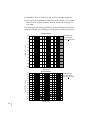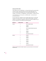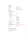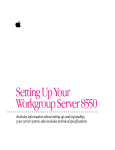
1
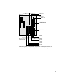
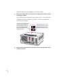
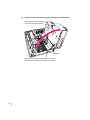
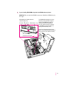
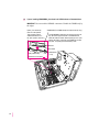
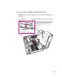
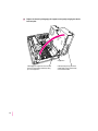
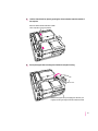
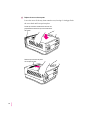
Technical Information Specifications for Power Macintosh 7600 series computers Technical Information Main unit Processor A PowerPC™ 604 processor with the following features: m 132 megahertz (MHz) m built-in floating point unit (FPU) m 44 MHz system bus m fully upgradable Memory m 16 megabytes (MB) of dynamic random-access memory (DRAM) supplied in removable DIMMs, expandable to a maximum of 512 MB m 2 MB of built-in video RAM (VRAM) supplied in removable DIMMs, expandable to a maximum of 4 MB m 4 MB of read-only memory (ROM) m 8 kilobytes (K) of nonvolatile parameter memory m 256K of static RAM supplied in a removable DIMM, used as a Level 2 cache for the PowerPC microprocessor 2 DRAM, VRAM, and cache configurations You can have memory—dynamic random-access memory (DRAM) or video random-access memory (VRAM)—added to your computer in packages called Dual Inline Memory Modules, or DIMMs. You can also upgrade your computer’s cache by installing a DIMM. DRAM configurations Your computer can use any DRAM configuration with DIMMs of these sizes: 8, 16, 32, or 64 MB. The exact configuration depends on the density of the DRAM chips that are mounted on the DIMMs. (The DIMMs support both 2K and 4K refresh rates.) You can increase your computer’s DRAM to up to 512 MB. The main logic board has eight slots where DIMMs can be installed. To increase DRAM to the maximum of 512 MB, have an Apple-authorized dealer or service provider fill all eight slots with 64 MB DIMMs. You can also fill slots with 8, 16, or 32 MB DIMMs. Note: 128 MB DIMMs are available and can fit in the computer’s memory slots to increase DRAM to as much as 1 gigabyte (GB). These DIMMs have not been tested for use with Power Macintosh 7600 computers, however. IMPORTANT The DIMMs should be 64-bit-wide, 168-pin fast-paged mode, with 70-nanosecond (ns) RAM access time or faster. The Single Inline Memory Modules (SIMMs) from older Macintosh computers are not compatible with your computer and should not be used. If you decide to have additional DRAM installed in your computer, the DIMMs can be installed one-at-a-time in any order in any of the memory slots. However, if you wish to take advantage of your computer’s memory interleaving capability, which provides maximum performance, you must have the DIMMs installed in pairs, and in paired slots. (Slots are paired A1 and B1, A2 and B2, and so on. It doesn’t matter which pairs you use or the order in which you use them, as long as the DIMMs are installed in paired slots.) Memory interleaving allows the computer to read or write to its memory at the same time that other memory reads or writes are occurring, thus providing faster performance. 3 VRAM configurations Video RAM (VRAM), like standard DRAM, is also provided in DIMMs. Your computer comes with 2 MB of video RAM installed in two 1 MB DIMMs. (These DIMMs are installed in bank 1.) Your computer’s VRAM can be expanded to a maximum of 4 MB by adding two 1 MB DIMMs to bank 2. Both DIMMs must be added at the same time. IMPORTANT The VRAM DIMMs must be 32-bit-wide, 112-pin fast-paged mode with 70-ns RAM access time or faster. Do not use the 256K or 512K VRAM SIMMs used in older Macintosh computers. Cache configurations Your computer can support a cache up to a maximum of 4 MB. Cache DIMMs are available in various sizes from 256K to 1 MB. Adding DRAM or VRAM, or upgrading the cache WARNING Although instructions for installing DIMMs are provided in this manual, Apple Computer strongly recommends that you have an Apple-certified technician install additional DRAM, VRAM, or cache. Consult the service and support information that came with your computer for instructions on how to contact an Apple-authorized service provider or Apple for service. If you install additional DIMMs yourself, you risk damaging your equipment, and this damage is not covered by the limited warranty on your computer. See an Appleauthorized dealer or service provider for additional information about this or any other warranty question. 4 RAM cache slot Bank 2 slot Bank 1 slot Bank 2 slot Bank 1 slot VRAM DIMM slots DRAM DIMM slots* (front of computer) B4 slot B3 slot B2 slot B1 slot A4 slot A3 slot A2 slot A1 slot *When installing DRAM, for best performance, fill paired slots. (Slots are paired A1 and B1, then A2 and B2, and so on. It doesn’t matter which pairs you use or the order in which you use them.) 5 DRAM, VRAM, and cache DIMMs are installed as follows: 1 Make sure the voltage switch is set correctly for the voltage system to which you will be connecting the computer. If you don’t know the voltage used in the country you’re in, refer to the table, “Voltages for Different Locations,” in Chapter 1 of the user’s manual that came with your computer. Check to see that the voltage switch on the back of your computer is properly set before you plug it in. If you need to change the setting, insert a small screwdriver here and slide the switch. 2 6 Set the switch to show “115” for voltages in the 100–130V range. Set the switch to show “230” for voltages in the 200–270V range. Plug the power cord into the back of the computer and into an AC outlet. Make sure the computer is turned off. 3 Press the two release buttons under the front panel and slide the cover toward you approximately two inches. Locate the two release buttons under the front panel ledge with your fingertips. While pressing the release buttons, pull the top cover forward approximately two inches to release it from the chassis. 7 4 Remove the cover from the computer. After you’ve slid the cover forward about two inches, lift it straight up and off the computer. 8 5 Touch the metal part of the power supply case inside the computer to discharge static electricity. Always do this before you touch any parts, or install any components, inside the computer. IMPORTANT Both DIMMs and the components inside your computer can be damaged by static electricity. Be sure to follow the procedure given here for discharging static electricity. To avoid damaging DIMMs, handle them only by the edges—never touch the connectors. Power supply 9 6 Disconnect the power cord from the back of the computer. Remove the power cord from the back of the computer. 7 Flip out the support foot. Flip the support foot out until it snaps into its locked position. Support foot 10 8 Unlock the top chassis by pressing the release switches toward the inside of the computer. Move the release switches toward the inside of the computer to unlock the top chassis. 9 Using the tab shown below, lift the top chassis up to reveal the DRAM and cache slots. You can use this tab to lift the top chassis. 11 10 Swing the chassis up and insert the support arm in the hole as pictured below. Gently swing the top part of the chassis up so that it rests on the support foot. Support arm Be sure that the support arm engages this hole on the floor of the bottom chassis so that the top chassis is locked in place. 12 11 If you’re installing DRAM DIMMs, align them in the DRAM sockets as pictured. IMPORTANT Do not touch the DIMM’s connectors. Handle the DIMM only by the edges. DRAM DIMM (Your DIMM’s shape and components may vary.) Connectors Notches DRAM socket (1 of 8) The DRAM DIMM is designed to fit into the socket only one way. Be sure to align the notches in the DIMM with the small ribs inside the socket. With the ejector(s) in the “open” position (as shown), push down on the DIMM until it snaps into place. The ejector(s) will automatically “close.” Ejector (Your socket may have one or two ejectors. They should be pushed outward and down to be in the “open” position, as shown.) Ribs (inside socket) (Toward front of computer ) 13 12 If you’re installing VRAM DIMMs, place them in the VRAM sockets as illustrated below. IMPORTANT Do not touch the DIMM’s connectors. Handle the DIMM only by the edges. Ejector (Your socket may have one or two ejectors. They should be pushed outward and down to be in the “open” position, as shown.) VRAM DIMM (Your DIMM’s shape and components may vary.) The VRAM DIMM is designed to fit into the socket only one way. Be sure to align the notches in the DIMM with the small ribs inside the socket. With the ejector(s) in the “open” position (as shown), push down on the DIMM until it snaps into place. The ejector(s) will automatically “close.” Notches Connectors VRAM socket (1 of 4) Ribs (inside socket) (Toward front of computer 14 ) 13 If you’re installing a cache DIMM, insert the DIMM as illustrated below. IMPORTANT Do not touch the DIMM’s connectors. Handle the DIMM only by the edges. Cache DIMM socket Cache DIMM (Your DIMM’s shape and components may vary.) The cache DIMM is designed to fit into the socket only one way. Be sure to align the notches in the DIMM with the small ribs inside the socket. Connectors Notches Ribs (inside socket) (Toward front of computer ) 15 14 Replace the chassis by disengaging the support arm and gently swinging the chassis back into place. Support arm 1 Disengage the support arm from the hole on the floor of the bottom chassis by lifting up on the support arm. 16 2 Gently swing the top part of the chassis down until it rests securely on the bottom chassis. 15 Lock the chassis back into place by pressing the release switches toward the outside of the computer. Move the release switches toward the outside of the computer to lock the top chassis. 16 Unsnap the support foot and swing it back inside the computer housing. Release the support foot by unsnapping the catch with your fingertip, and swing the support foot back inside the chassis. 17 17 Replace the cover on the computer. Lower the cover all the way down onto the case, leaving a 2-inch gap. Push the cover back until it snaps into place. Set the top cover down so that there is about a 2-inch gap between the back of the top cover and the back of the chassis. Slide the top cover all the way back until it snaps into place. 18 Graphics modes The table on the following page shows the image sizes for monitors that can be connected to the monitor port, along with the number of colors or grays supported with 2 MB of VRAM and with the optional expansion to 4 MB of VRAM. (You can place monitors weighing up to 70 lbs. [31.75 kg] on top of your computer.) There are also many special PCI monitor cards available from other manufacturers that can support other monitors and special video requirements. See your Apple-authorized dealer for information. Note: On some monitors from manufacturers other than Apple, the connector pinout designates one pin for both green video and timing synchronization. These “sync on green” monitors are not compatible with Power Macintosh computers. If you’re not sure what type of monitor you have, check with your dealer. 19 Colors or grays supported Monitor VIS* Resolution 2 MB VRAM 4 MB VRAM maximum colors** maximum colors** Screen refresh rates Vertical Horizontal 12" RGB N/A 512 by 384 Millions Millions 60 Hz 24.48 kHz 12" Monochrome N/A 640 by 480 256 256 67 Hz 34.971 kHz 13" RGB Hi-Res N/A 640 by 480 Millions Millions 67 Hz 34.971 kHz 14" RGB Hi-Res 11.5" 640 by 480 Millions Millions 67 Hz 34.971 kHz VGA *** 640 by 480 800 by 600 800 by 600 800 by 600 1024 by 768 1024 by 768 1024 by 768 Millions Millions Millions Millions Thousands Thousands Thousands Millions Millions Millions Millions Millions Millions Millions 60 Hz 60 Hz 72 Hz 75 Hz 60 Hz 72 Hz 75 Hz 31.505 kHz 39.921 kHz 48.1 kHz 47.933 kHz 48.294 kHz 58.286 kHz 60.093 kHz Full-page Monochrome N/A 640 by 870 256 256 75 Hz 68.773 kHz Full-page RGB *** 640 by 870 Thousands Millions 75 Hz 68.773 kHz 14" AudioVision 11.5" 640 by 480 Millions Millions 67 Hz 35 kHz 16" color 14.8" 832 by 624 Millions Millions 75 Hz 49.670 kHz 19" color *** 1024 by 768 Thousands Millions 75 Hz 60.060 kHz Two-page Monochrome N/A 1152 by 870 256 256 75 Hz 68.476 kHz Two-page RGB 11.5" 1152 by 870 Thousands Millions 75 Hz 68.476 kHz Multiple Scan 15 13.3" 640 by 480 832 by 624 Millions Millions Millions Millions 67 Hz 75 Hz 34.971 kHz 49.670 kHz Multiple Scan 17 16.1" 640 by 480 832 by 624 1024 by 768 Millions Millions Thousands Millions Millions Millions 67 Hz 75 Hz 75 Hz 34.971 kHz 49.670 kHz 60.060 kHz Multiple Scan 20 19.1" 640 by 480 832 by 624 1024 by 768 1152 by 870 1280 by 1024 Millions Millions Thousands Thousands 256 Millions Millions Millions Millions Thousands 67 Hz 75 Hz 75 Hz 75 Hz 75 Hz 34.971 kHz 49.670 kHz 60.060 kHz 68.476 kHz 79.964 kHz *Viewable Image Size **256=image depth of 8 bits, thousands=image depth of 16 bits, millions=image depth of 32 bits ***Refer to the manual that came with your monitor to determine VIS. N/A=not available 20 Video support All video input ports support 24-bit RGB format as well as 16-bit component (YUV) format. Video input ports Connector Standard Resolution Composite/S-video NTSC 256 by 192 320 by 240 512 by 384 640 by 480 Composite/S-video PAL/SECAM 320 by 240 384 by 288 640 by 480 768 by 576 Internal disk drives The following drives have been installed in your computer at the factory: m Apple SuperDrive 1.4 MB high-density floppy disk drive m Apple SCSI hard disk drive Some Power Macintosh computers have an optional built-in CD-ROM drive (5.25-inch, 1/2-height 8X-speed). You can have additional internal drives installed by an Apple-authorized dealer or service provider. Clock/calendar m CMOS custom circuitry with long-life lithium battery Keyboard m Supports all Apple Desktop Bus (ADB) keyboards Mouse m Supports all models of the ADB mouse 21 Interfaces m One Apple Desktop Bus (ADB) port supporting up to three ADB input devices (such as a trackball, keyboard, or mouse) daisy-chained through a low-speed, synchronous serial bus. m Monitor port supporting color and grayscale monitors of various sizes and resolutions. (See “Graphics Modes” earlier in this booklet.) m Three internal expansion slots supporting Peripheral Component Interconnect (PCI) expansion cards. Install only expansion cards that come with Macintosh drivers and are compliant with the PCI 2.0 standard. NuBus™ cards cannot be used in these expansion slots. m Two RS-232/RS-422 serial GeoPort-compatible serial ports, 230.4 Kbits per second maximum (up to 2.048 Mbits per second if clocked externally). m One built-in Ethernet 10BASE-T connector for direct connection to 10BASE-T networks. (If both AAUI and 10BASE-T connectors are plugged in, the computer uses the 10BASE-T connector by default.) m One built-in Apple Ethernet AAUI connector for connecting to high-speed Ethernet networks. Requires the appropriate AAUI transceiver adapter (10BASE-T, thin coaxial, or thick coaxial). m One 3.5 mm sound output port for headphones or line-level devices. m One 3.5 mm sound input port for stereo sound input. The sound input port supports the Apple PlainTalk Microphone that comes with some Macintosh computers. The sound input port also supports a standard stereo (miniplug-to-RCA) cable adapter for connecting stereo equipment to your computer. It does not support the omnidirectional microphone (the round microphone shipped with some earlier models of Macintosh) or the attenuated RCA adapter provided with some models of Macintosh. m One pair of RCA-type audio ports for stereo input (left and right). m One pair of RCA-type audio ports for stereo output (left and right). m Two video input ports that support the NTSC, PAL, and SECAM video standards. m One external standard SCSI interface that supports up to seven external SCSI devices, or one internal plus six external SCSI devices. An internal SCSI device can be connected to this interface by an Apple-authorized dealer or service provider. 22 IMPORTANT Some older SCSI devices may require updated drivers. (A “driver” is special software that is installed in your System Folder.) Contact the device manufacturer for information on obtaining driver software. m One internal fast SCSI interface that supports the internal hard disk and optional CD-ROM drive. One additional SCSI device can be connected to the internal SCSI interface by an Apple-authorized dealer or service provider. IMPORTANT The factory-installed internal hard disk is terminated. If another SCSI device is attached to the internal SCSI interface, it must not be terminated. The internal SCSI interface can contain only one terminated device; if you attach more than one terminated device to the internal SCSI interface, damage to the computer’s main logic board can occur. Audio system m Custom sound circuitry, including stereo generator (digital-to-analog converter, or DAC)—capable of driving stereo miniplug headphones or audio equipment—and stereo sampling hardware (analog-to-digital converter, or ADC) for recording stereo sound m 16-bit stereo input and output m Sample rates of 44.1 and 22.05 kilohertz (kHz) Typical specifications m Sound input connector line level: 2.8 volts peak-to-peak (Vpp) nominal, into 3.0-kilohm (kΩ) impedance (minimum) m RCA-type input connector line level: 2.4 Vpp nominal into 13.5-kΩ impedance (minimum) m Sound output connector line level: 2.7 Vpp nominal, into 32-kΩ impedance m RCA-type output connector level: 2.9 Vpp nominal into 2-kΩ impedance (minimum) m Sound input signal-to-noise ratio (SNR): >83 decibels (dB) A-weighted with no audible discrete tones m RCA-type input SNR: >77 dB A-weighted with no audible discrete tones m Sound output SNR: >84 dB A-weighted with no audible discrete tones m RCA-type output SNR: >84 dB A-weighted with no audible discrete tones 23 m Bandwidth: 10 Hz to 18 kHz (+0.1 dB, –3.0 db) at 44.1-kHz sample rate m RCA-type input total harmonic distortion plus noise (THD + N): less than 0.018 percent A-weighted; measured 10 Hz to 30 kHz with a 2.4-Vpp sine wave input The following graphs show typical data for the Power Macintosh 7600. (Your computer’s data may vary, depending on the equipment you have connected.) Frequency Response 1.00 Digital loop-through 44.1 kHz sample rate RCA input RCA output 0.00 Amplitude (dBr) ref. to 1kHz -1.00 -2.00 -3.00 -4.00 -5.00 -6.00 -7.00 -8.00 -9.00 10 100 1k Frequency (Hz) 10k 20k Signal-to-Noise Ratio 0.0 Digital loop-through 44.1 kHz sample rate RCA input RCA output -10.0 -20.0 Amplitude (dBr) ref. to clipping -30.0 -40.0 -50.0 -60.0 -70.0 -80.0 -90.0 -100.0 -110.0 -120.0 -130.0 10 24 100 1k Frequency (Hz) 10k 20k Total Harmonic Distortion vs. Amplitude Total Harmonic Distortion (%) 1 Digital loop-through 44.1 kHz sample rate RCA input RCA output 0.1 0.08 0.06 A-WEIGHTED 0.04 0.02 0.010 0.2 1.0 Amplitude (Vpp) 2.0 3.0 Video system Video input m Type: composite or S-video m Timing: industry standard NTSC/PAL/SECAM m Polarity: sync negative m Level: 8 Vpp minimum to 2.0 peak-to-peak (p-p) maximum (“S” chroma level 1.4 Vpp maximum) m Impedance: 75 ohms (Ω) internally terminated m DC offset: +/– 1.0 volts (V) maximum AC line input m Line voltage: 100–130 V alternating current (AC) and 200–270 V AC, RMS single phase, manually configured m Frequency: 50–60 Hz m Power: 298 watts maximum continuous; 453 watts peak input 25 AC line output m Output receptacle: 100–120 V, 3 amperes (A) AC, 220–240 V, 1.5 A AC RMS (determined by actual input voltage); 3 A maximum at 100 V DC power m Continuous output: 150 watts Current type Maximum current* +5 V 20 A** +5 V (trickle) 0.1 A +3.3 V 10 A** +12 V 5A –12 V 0.75 A *Total power output cannot exceed 150 W. **Note: Not more than 25 A total combined current. Power requirements for devices you can connect Apple Desktop Bus (ADB) m Mouse draws up to 10 milliamperes (mA) m Keyboard draws 25–80 mA (varies with keyboard model used) m Maximum current available for all ADB devices: 500 mA Note: The ADB port can support up to three daisy-chained ADB devices. Audio and telecommunications devices The following table shows power allowances for external devices connected to input ports. 26 Device Voltage Current Power Microphone +5 V 20 mA 100 mW GeoPort telecom adapter +5 V 500 mA 2.5 W S-video input connector +12 V 250 mA 3W Expansion cards and devices If you add an expansion card, a 5.25-inch storage device, or a 3.5-inch storage device to your Macintosh computer, make sure the component’s power requirements don’t exceed the maximum power allowances allocated to it by the computer. The maximum power allowances for expansion cards in your computer can accommodate three 15-watt or two 25-watt cards. Detailed guidelines are presented in the following table. Device Voltage Current Power Expansion card (15 watts)* +5 V +12 V –12 V +3.3 V 3A 0.500 A 0.100 A 2A 15 W 6W 1.2 W 6.6 W Expansion card (25 watts)** +5 V +12 V –12 V +3.3 V 5A 0.500 A 0.100 A 2A 25 W 6W 1.2 W 6.6 W Storage device (such as a CD-ROM drive) +5 V +12 V +12 V 9A 3A 7.5 A peak*** 45 W 36 W — *15-watt expansion cards should not consume more than 15 watts of power total. **25-watt cards should not consume more than 25 watts of power total. ***Peak power is for startup only and must not occur in normal operation. 27 Assigning SCSI ID numbers Your computer has two SCSI chains: an internal chain and an external chain. All devices on the same SCSI chain must have unique ID numbers, but devices on different SCSI chains may use the same SCSI ID number. (For example, you could have a CD-ROM drive with ID number 3 connected to the internal SCSI chain and a tape drive with ID number 3 connected to the external SCSI chain.) The drives that were installed in your computer at the factory, as well as the computer itself have already reserved certain SCSI ID numbers. Other ID numbers are available for assignment to SCSI devices that are added after you buy your computer, as described in the following table. SCSI chain Internal* External SCSI ID number Device 0 factory-installed hard disk 1 available 2 available 3 factory-installed CD-ROM drive (optional) 4 available 5 available 6 available 7 Power Macintosh computer 0 available 1 available 2 available 3 available 4 available 5 available 6 available 7 Power Macintosh computer *Although 5 or 6 SCSI ID numbers are available for assignment, only one other SCSI device can be connected to the internal SCSI chain. 28 Size and weight Weight Height Width Depth Main unit 9.98 kg* 22 lbs.* 156 mm 6.15 in. 365 mm 14.37 in. 430 mm 16.93 in. Mouse 0.11 kg 4 oz. 33 mm 1.3 in. 61 mm 2.4 in. 107 mm 4.2 in. *Weight varies depending on type of hard disk and may be greater if a 5.25-inch device, such as a CD-ROM drive, is installed. Maximum supportable monitor weight m 70 lbs. (31.75 kg) Environment Operating temperature m 10° C to 40° C (50° F to 104° F) Storage temperature m –40° C to 47° C (–40° F to 116.6° F) Relative humidity m 5 percent to 95 percent (noncondensing) Altitude m 0 to 3048 m (0 to 10,000 ft.) 29 Specifications for optional CD-ROM drive m Disc diameter 120 millimeters (mm) (5.25 inches) and 80 mm m Scanning velocity 1.2–1.4 meters per second (normal speed) m Rotation speed Varies over radius Normal speed ~530 to 230 revolutions per minute (rpm) Double speed ~1060 to 460 rpm Eight-times speed ~4240 to 1840 rpm m Latency (average) Varies over radius Normal speed ~55 to 130 milliseconds (ms) Double speed ~27.5 to 65 ms Eight-times speed ~6.88 to 16.25 ms m Blocks per rotation ~8.4 to 19.5 variable m Average access time (typical) Normal speed 380 ms Double speed 270 ms Eight-times speed 160 ms Data m Data capacity 656 megabytes (MB), Mode 1 748 MB, Mode 2 m Number of blocks per disc 336,150 m Data per block 2048 bytes, Mode 1 2336 bytes, Mode 2 m Address description Minutes, seconds, blocks Audio capacity m Playing time 30 74 minutes, 42 seconds Modes supported m Audio CD m CD-ROM Modes 1 and 2 m CD-ROM XA Mode 2, Forms 1 and 2 m CD-I Mode 2, Forms 1 and 2 m Photo CD Single-session and multisession m Video CD Data streaming and transfer rates m Blocks per second Normal speed 75 Double speed 150 Eight-times speed 600 m User kilobytes (K) per second Normal speed 150K, Mode 1 171.1K, Mode 2 Double speed 300K, Mode 1 342.2K, Mode 2 Eight-times speed 1200K, Mode 1 1368.8K, Mode 2 m SCSI bus burst rate (typical) Asynchronous 5.0 MB per second Synchronous 5.0 MB per second Power consumption (typical) +5 V DC 350 milliamperes (mA) +12 V DC 300 mA Laser m Type: Semiconductor GaAlAs laser m Wavelength: 770 to 795 nanometers m Output power: 0.2 to 0.6 milliwatts m Beam divergence: 55° 31 © 1996 Apple Computer, Inc. All rights reserved. Apple, the Apple logo, Apple SuperDrive, GeoPort, Macintosh, PlainTalk, and Power Macintosh are trademarks of Apple Computer, Inc., registered in the U.S. and other countries. Apple Desktop Bus and AudioVision are trademarks of Apple Computer, Inc. NuBus is a trademark of Texas Instruments. PowerPC is a trademark of International Business Machines Corporation, used under license therefrom. 030-9824-A Printed in U.S.A.