1
HFC
utilized
SPLIT-TYPE, HEAT PUMP AIR CONDITIONERS
R410A
April 2013
TECHNICAL & SERVICE MANUAL
[Model name]
<Branch box>
PAC-AK50BC
PAC-AK51BC
PAC-AK52BC
PAC-AK53BC
PAC-AK30BC
PAC-AK31BC
PAC-AK32BC
[Service Ref.]
PAC-AK50BC
PAC-AK51BC
PAC-AK52BC
PAC-AK53BC
PAC-AK30BC
PAC-AK31BC
PAC-AK32BC
No. OCH508
REVISED EDITION-A
Revision:
• PAC-AK53BC and PACAK32BC have been added
in REVISED EDITION-A.
• Some descriptions have
been modified.
• Please void OCH508.
NOTE:
• This service manual
describes technical data of
branch box. As for indoor
units and outdoor unit,
refer to its service manual.
(Indispensable optional parts for MXZ-8A series and MXZ-8B series. )
CONTENTS
1.
2.
3.
4.
5.
6.
7.
8.
SAFETY PRECAUTION ·······································
2
OVERVIEW OF UNIT ···········································
5
SPECIFICATIONS ················································
8
OUTLINES AND DIMENSIONS ···························
9
WIRING DIAGRAM ·············································
10
REFRIGERANT SYSTEM DIAGRAM ·················
11
TROUBLESHOOTING ········································
12
DISASSEMBLY PROCEDURE ···························
23
BRANCH BOX
PARTS CATALOG (OCB508)
1
SAFETY PRECAUTION
1-1. ALWAYS OBSERVE FOR SAFETY
Before obtaining access to terminal, all supply
circuit must be disconnected.
1-2. CAUTIONS RELATED TO NEW REFRIGERANT
Cautions for units utilizing refrigerant R410A
Use new refrigerant pipes.
Make sure that the inside and outside of refrigerant piping is clean and it has no contaminants
such as sulfur, oxides, dirt, shaving particles, etc,
which are hazard to refrigerant cycle.
In addition, use pipes with specified thickness.
Contamination inside refrigerant piping can cause deterioration of refrigerant oil etc.
Store the piping indoors, and both ends of the
piping sealed until just before brazing.
(Leave elbow joints, etc. in their packaging.)
Do not use refrigerant other than R410A.
If other refrigerant (R22 etc.) is used, chlorine in refrigerant can cause deterioration of refrigerant oil etc.
Use a vacuum pump with a reverse flow check
valve.
Vacuum pump oil may flow back into refrigerant cycle and
that can cause deterioration of refrigerant oil etc.
Use the following tools specifically designed for
use with R410A refrigerant.
The following tools are necessary to use R410A refrigerant.
Gauge manifold
Charge hose
Gas leak detector
Torque wrench
If dirt, dust or moisture enters into refrigerant cycle, that can
cause deterioration of refrigerant oil or malfunction of compressor.
The refrigerant oil applied to flare and flange
connections must be ester oil, ether oil or
alkylbenzene oil in a smalll amount.
If large amount of mineral oil enters, that can cause deterioration of refrigerant oil etc.
Charge refrigerant from liquid phase of gas
cylinder.
Tools for R410A
Flare tool
Size adjustment gauge
Vacuum pump adaptor
Electronic refrigerant
charging scale
Handle tools with care.
If dirt, dust or moisture enters into refrigerant cycle, that can
cause deterioration of refrigerant oil or malfunction of compressor.
If the refrigerant is charged from gas phase, composition
change may occur in refrigerant and the efficiency will be
lowered.
Do not use a charging cylinder.
Use the specified refrigerant only.
Ventilate the room if refrigerant leaks during
operation. If refrigerant comes into contact with
a flame, poisonous gases will be released.
Never use any refrigerant other than that specified.
Doing so may cause a burst, an explosion, or fire when the
unit is being used, serviced, or disposed of.
Correct refrigerant is specified in the manuals and on the
spec labels provided with our products.
We will not be held responsible for mechanical failure,
system malfunction, unit breakdown or accidents caused
by failure to follow the instructions.
OCH508A
If a charging cylinder is used, the composition of refrigerant will change and the efficiency will be lowered.
2
[1] Cautions for service
(1) Perform service after recovering the refrigerant left in unit completely.
(2) Do not release refrigerant in the air.
(3) After completing service, charge the cycle with specified amount of refrigerant.
(4) When performing service, install a filter drier simultaneously.
Be sure to use a filter drier for new refrigerant.
[2] Additional refrigerant charge
When charging directly from cylinder
· Check that cylinder for R410A on the market is syphon type.
· Charging should be performed with the cylinder of syphon stood vertically. (Refrigerant is charged from liquid phase.)
Unit
Gravimeter
[3] Service tools
(1) Use the below service tools as exclusive tools for R410A refrigerant.
No.
Tool name
1
Gauge manifold
2
Charge hose
3
4
5
6
Electronic scale
Gas leak detector
Adaptor for reverse flow check
Refrigerant charge base
7
Refrigerant cylinder
8
Refrigerant recovery equipment
OCH508A
Specifications
· Only for R410A
· Use the existing fitting specifications. (UNF1/2)
· Use high-tension side pressure of 5.3MPa·G or over.
· Only for R410A
· Use pressure performance of 5.09MPa·G or over.
· Use the detector for R134a, R407C or R410A.
· Attach on vacuum pump.
· Only for R410A
· Cylinder with syphon
3
· Top of cylinder (Pink)
(2) Cautions for refrigerant piping work
New refrigerant R410A is adopted for replacement inverter series. Although the refrigerant piping work for R410A is same
as for R22, exclusive tools are necessary so as not to mix with different kind of refrigerant. Furthermore as the working
pressure of R410A is 1.6 times higher than that of R22, their sizes of flared sections and flare nuts are different.
1 Thickness of pipes
Because the working pressure of R410A is higher compared to R22, be sure to use refrigerant piping with thickness
shown below. (Never use pipes of 0.7 mm or below.)
Diagram below: Piping diameter and thickness
Nominal
Thickness (mm)
Outside
dimensions(inch) diameter (mm)
R410A
R22
0.8
0.8
6.35
1/4
0.8
0.8
9.52
3/8
0.8
0.8
12.70
1/2
1.0
1.0
15.88
5/8
—
1.0
19.05
3/4
2 Dimensions of flare cutting and flare nut
The component molecules in HFC refrigerant are smaller compared to conventional refrigerants. In addition to that,
R410A is a refrigerant, which has higher risk of leakage because of its working pressure higher than that of other refrigerants. Therefore, to enhance airtightness and intensity, flare cutting dimension of copper pipe for R410A has been specified separately from the dimensions for other refrigerants as shown below. The dimension B of flare nut for R410A also
has partly been changed to increase intensity as shown below. Set copper pipe correctly referring to copper pipe flaring
dimensions for R410A below. For 1/2” and 5/8”, the dimension B changes.
Use torque wrench corresponding to each dimension.
Dimension A
Dimension B
Flare cutting dimensions
Nominal
Outside
dimensions(inch)
diameter
6.35
1/4
9.52
3/8
12.70
1/2
15.88
5/8
19.05
3/4
(mm)
Dimension A ( +0
-0.4 )
R410A
R22
9.0
9.1
13.0
13.2
16.2
16.6
19.4
19.7
—
23.3
Flare nut dimensions
Nominal
dimensions(inch)
1/4
3/8
1/2
5/8
3/4
Outside
diameter
6.35
9.52
12.70
15.88
19.05
(mm)
Dimension B
R410A
R22
17.0
17.0
22.0
22.0
24.0
26.0
27.0
29.0
—
36.0
3 Tools for R410A (The following table shows whether conventional tools can be used or not.)
R410A tools
Can R22 tools be used? Can R407C tools be used?
Tool exclusive for R410A
Tool exclusive for R410A
Tool for HFC refrigerant
Tool exclusive for R410A
Tool exclusive for R410A
Ester oil and alkylbenzene
Ester oil:
Alkylbenzene oil: minimum amount
oil (minimum amount)
Prevent compressor malfunction Tool exclusive for R410A
Safety charger
when charging refrigerant by
spraying liquid refrigerant
Prevent gas from blowing out Tool exclusive for R410A
Charge valve
when detaching charge hose
Vacuum drying and air
Tools for other refrigerants can
Vacuum pump
(Usable if equipped
(Usable if equipped
with adopter for reverwith adopter for reverpurge
be used if equipped with adopse flow)
se flow)
ter for reverse flow check
Flaring work of piping
Tools for other refrigerants
Flare tool
(Usable by adjusting
(Usable by adjusting
can be used by adjusting
flaring dimension)
flaring dimension)
flaring dimension
Bend the pipes
Tools for other refrigerants can be used
Bender
Tools for other refrigerants can be used
Cut the pipes
Pipe cutter
Tools for other refrigerants can be used
Welder and nitrogen gas cylinder Weld the pipes
Tools for other refrigerants can be used
Refrigerant charging scale Refrigerant charge
Vacuum gauge or thermis- Check the degree of vacuum. (Vacuum Tools for other refrigerants
valve prevents back flow of oil and refri- can be used
tor vacuum gauge and
gerant to thermistor vacuum gauge)
vacuum valve
Refrigerant charge
Charging cylinder
Tool exclusive for R410A
: Prepare a new tool. (Use the new tool as the tool exclusive for R410A.)
: Tools for other refrigerants can be used under certain conditions.
: Tools for other refrigerants can be used.
Tools and materials
Gauge manifold
Charge hose
Gas leak detector
Refrigerant recovery equipment
Refrigerant cylinder
Applied oil
OCH508A
Use
Air purge, refrigerant charge
and operation check
Gas leak check
Refrigerant recovery
Refrigerant charge
Apply to flared section
4
2
OVERVIEW OF UNIT
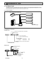
2-1. SYSTEM OUTLINE
The additional connection of the Branch Box together with employment of the compact trunk-looking outdoor unit can
successfully realizes a long distance piping for big houses. Equipped with a microprocessor, the Branch Box can translate the transmission signal of indoor units to achieve the optimum control.
2-1-1. System example
Indoor unit (Ceiling concealed type)
Indoor unit
(Wall mounted type)
Branch Box
Outdoor unit
2-1-2. Method for identifying
■ Outdoor unit
Number of connectable indoor units (MAX.)
Model type
M X Z – 8 B 140 V A
Control and refrigerant
A : New A control and R410A
Power supply
V: Single phase 220/230/240V
Y: 3-Phase
380/400/450V
Multi type heat pump
inverter outdoor unit
■ Branch box
Indicates equivalent to rated cooling capacity.
(0.1kW)
Applicable refrigerant
A : R410A
Symbol of factory
P A C – A K 5 2 BC
Branch box (Controller)
Model type
(Indispensable)
Optional parts
OCH508A
50Hz
50Hz
Number of branches
5 : 5 branches
3 : 3 branches
5
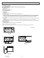
2-2. INSTALLATION
2-2-1. Space required for Installation and servicing for Branch box.
(1) Front View (Fig. 2-1)
A Branch box
B On the side of piping
(2) Side View (Fig. 2-2, Fig. 2-3)
C For indoor installations
D Ceiling board
E Maintenance hole
F PCB side
*1: A minimum 350 mm is required for 90° bends in refrigerant piping.
*2: A is “Min. 200 mm”.
(Premise: The slope of drain piping is securable 1/100 or more. Required 200 mm or more, when not securable.)
In the case of less than 200 mm (for example A is 100 mm), the exchange work of Branch box from a maintenance hole
becomes difficult (Only exchange work of a PCB, linear expansion valve coils, sensors and drain pan is possible).
*3: B is “ □ 600”.
In the case of “ □ 450”, prepare a maintenance hole at a PCB side as it is shown in Fig. 2-3, and “Min. 300 mm” is needed
as distance A.
In the case of less than 300 mm (for example A is 100 mm), the exchange work of Branch box, linear expansion
valve coils, sensors, and drain pan from a maintenance hole becomes difficult. Only exchange work of a PCB is possible.
(3) Top View (Fig. 2-4)
G Refrigerant piping
H When facing in the opposite direction to the refrigerant piping.
NOTE1: The branch box is only for indoor use.
NOTE2: Please attach the special optional cover (PAC-AK350CVR-E) to install branch box in the outdoors.
(1)
unit : mm
450
Min. 250
Min.
50
Min. 30
(2)
Fig. 2-1
198
*1
Min.
250
A
250
A
*2
Min.
280
450
180-200
B *3
Fig. 2-2
Fig. 2-3
(3)
Min. 250
Fig. 2-4
OCH508A
6
2-3. SIMPLIFIED PIPING SYSTEM
Piping connection size
A
Liquid
(mm)
W9.52
Gas
(mm)
W15.88
B
The piping connection size differs according to the type and capacity of indoor units.
Match the piping connection size of branch box with indoor unit.
If the piping connection size of branch box does not match the piping connection size of
indoor unit, use optional different-diameter (deformed) joints to the branch box side.
(Connect deformed joint directly to the branch box side.)
Flare connection employed. (No brazing!)
■ In case of using 1-branch box
Flare connection employed (No brazing)
Branch box
A
B
B
B
B
B
■ In case of using 2-branch boxes
2 branches pipe (joint)
: optional parts
A
A
Branch box #1
A
B
B
B
B
B
Branch box #2
■ Installation procedure (2 branch pipe (joint))
Refer to the installation manuals of MSDD-50AR-E and MSDD-50BR-E.
OCH508A
7
3
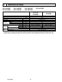
SPECIFICATIONS
PAC-AK50BC
PAC-AK30BC
PAC-AK51BC
PAC-AK31BC
PAC-AK52BC
PAC-AK32BC
Model name
Connectable number of indoor units
Power supply (from outdoor unit)
Input
Running current
External finish
Drain hose size (on site)
Width
Dimensions
Depth
Height
Weight
Piping
connection
(Flare)
Branch (indoor side)*
Wiring
To indoor unit
To outdoor unit
Main (outdoor side)
kW
A
Liquid
Gas
Liquid
Gas
mm
mm
mm
mm
kg
mm
mm
mm
mm
PAC-AK53BC
PAC-AK50BC
PAC-AK30BC
PAC-AK51BC
PAC-AK31BC
PAC-AK52BC
PAC-AK32BC
PAC-AK53BC
MAX. 5
MAX. 3
Single phase, 220/230/240V, 50Hz, Single phase, 220V, 60Hz
0.003
0.05
Galvanized sheets
O.D.20 (VP-16)
450
280
198
9.3
8.1
:6.35 5 {A,B,C,D,E}
:6.35 3 {A,B,C}
:9.52 4 {A,B,C,D}, :12.7 % 1{E}
:9.52 3 {A,B,C}
:9.52
:15.88
Each 3-wire, plus earth wire
3-wire, plus earth wire
* The piping connection size differs according to the type and capacity of indoor units. Match the piping connection size for indoor
and branch box. If the piping connection size of branch box does not match the piping connection size of indoor units, use
optional different-diameter (deformed) joints to the branch box side. (Connect deformed joint directly to the branch box side.)
OCH508A
8
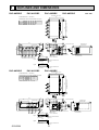
4
OUTLINES AND DIMENSIONS
PAC-AK50BC
PAC-AK51BC
PAC-AK52BC
unit: mm
PAC-AK53BC
SUSPENSION BOLT PITCH
320
SUSPENSION BOLT : W3/8 (M10)
REFRIGERANT PIPE FLARED CONNECTION (inch)
B
C
D
E
LIQUID PIPE 1/4
1/4
1/4
1/4
1/4
3/8
GAS PIPE
3/8
3/8
3/8
1/2
5/8
3/8
TO OUTDOOR UNIT
SUSPENSION BOLT PITCH
A
24
402
DRAIN HOSE SIZE : O.D. 20 (VP-16)
12
450
91
95
73
55
280
61
50
39
3-ELECTRIC WIRE INLET
34
25
25
25
35
25
75
TO OUTDOOR UNIT
200
75
23
Type A
FLEXIBLE DRAIN HOSE
(ACCESSORY)
ELECTRIC COVER
TERMINAL BLOCK
TO OUTDOOR UNIT
SERVICE PANEL
(for LEV, THERMISTOR)
:20
75
3-WIRE BAND
21
DRAIN PIPE CONNECTION
(VP-16)
:20
75
TB2B
68
25
TB3A
A
TB3B
65
A
B
TB3D
198
B
C
C
TB3C
D
D
TB3E
E
E
TERMINAL BLOCK
TO INDOOR UNIT
70
39
TO INDOOR UNIT
79
DRAIN PIPE CONNECTION
(VP-16)
200
Type B
FLEXIBLE DRAIN HOSE
(ACCESSORY)
PAC-AK30BC
PAC-AK31BC
PAC-AK32BC
SUSPENSION BOLT PITCH
320
SUSPENSION BOLT : W3/8 (M10)
REFRIGERANT PIPE FLARED CONNECTION (inch)
C
1/4
1/4
3/8
GAS PIPE
3/8
3/8
5/8
3/8
SUSPENSION BOLT PITCH
A
TO OUTDOOR UNIT
B
LIQUID PIPE 1/4
24
402
DRAIN HOSE SIZE : O.D. 20 (VP-16)
12
450
39
34
25
35
25
68
25
75
75
3-WIRE BAND
21
TO OUTDOOR UNIT
200
SERVICE PANEL
(for LEV, THERMISTOR)
23
:20
FLEXIBLE DRAIN HOSE
(ACCESSORY)
DRAIN PIPE CONNECTION
(VP-16)
:20
Type A
DRAIN PIPE CONNECTION
(VP-16)
200
Type B
FLEXIBLE DRAIN HOSE
(ACCESSORY)
OCH508A
TB3A
A
TERMINAL BLOCK
TO INDOOR UNIT
TB2B
B
3-ELECTRIC WIRE INLET
70
A
B
C
39
TB3B
65
50
TB3C
198
79
61
TO INDOOR UNIT
C
280
95
91
73
205
9
ELECTRIC COVER
TERMINAL BLOCK
TO OUTDOOR UNIT
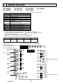
5
WIRING DIAGRAM
PAC-AK50BC
PAC-AK30BC
PAC-AK51BC
PAC-AK31BC
PAC-AK52BC
PAC-AK32BC
PAC-AK53BC
Note : " PAC - AK30 . 50BC, PAC - AK31 . 51BC, PAC-AK32 . 52BC, PAC-AK53BC " is only for R410A.
SYMBOL
B.C
F1 <B.C>
SW1<B.C>
CNM<B.C>
LED1~5< B.C>
LEV-A~E
TH-A~E
NAME
Branch box controller board
Fuse 250V 6.3A
Switch for service
Connector
Light emitting diode
Linear expansion valve
Thermistor
Pipe temp.detection / Gas
(0 / 15k, 25 / 5.4k)
Terminal block / To outdoor unit
Terminal block / To indoor unit - A
Terminal block / To indoor unit - B
Terminal block / To indoor unit - C
Terminal block / To indoor unit - D
Terminal block / To indoor unit - E
TB2B
TB3A
TB3B
TB3C
TB3D
TB3E
Note
1. At servicing for outdoor unit, always follow the wiring diagram of Outdoor unit.
2. Symbols used in wiring diagram above are,
: terminal block,
: connector.
(Combination of indoor units)
Enter the location of combined indoor units with model name in each
blank below because it is necessary for service and maintenance.
Indoor unit - A Indoor unit - B Indoor unit - C Indoor unit - D Indoor unit - E
* Setup of SW1
Make it the same setup as former
when exchanging PCB.
(PAC - AK50/51/52/53BC only) TB3E
YLW
S1
TO INDOOR
ORN
S2
UNIT -E
S3 BRN
(PAC - AK50/51/52/53BC only) TB3D
YLW
S1
TO INDOOR
S2 ORN
UNIT -D
S3 BRN
TB3C
S1 YLW
TO INDOOR
S2 ORN
UNIT -C
S3 BRN
TB3B
S1 YLW
TO INDOOR
S2 ORN
UNIT -B
S3 BRN
TB3A
S1 YLW
TO INDOOR
S2 ORN
UNIT -A
S3 BRN
TB2B
S1 YLW
TO OUTDOOR
S2 ORN
UNIT
S3 BRN
The black square (■) indicates a switch position.
ON
OFF
5
TB3E
3 (GRN)
1
LED1 LED2 LED3 LED4 LED5
SW1 *
1 2 3 4 5 6 7
8 9 10 11 12 13 14
TH-A 1
(WHT) 2
TH-A
CNM
TH-B 1
(RED) 2
TH-B
TH-C 1
(BLU) 2
TH-C
TH-D 1
(BLK) 2
TH-D
TH-E 1
(GRN) 2
TH-E
5
TB3D
3 (BLK)
1
5
TB3C
3 (BLU)
1
5
TB3B
3 (RED)
1
5
TB3A
3 (WHT)
1
1 CN3C
3 (BLU)
3 CND
1 (ORN)
F1
TB1
OCH508A
B.C
10
LEV-A 1
(WHT) 6
6
LEV-B 1
(RED) 6
6
LEV-C 1
(BLU) 6
6
LEV-D 1
(BLK) 6
6
LEV-E 1
(GRN) 6
6
(PAC - AK50/51/52/53BC only)
LEV-A
LEV-B
LEV-C
LEV-D
LEV-E
(PAC - AK50/51/52/53BC only)
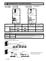
6
REFRIGERANT SYSTEM DIAGRAM
■ PAC-AK50BC
■ PAC-AK30BC
PAC-AK51BC
PAC-AK53BC
PAC-AK52BC
PAC-AK32BC
E
D
C
B
A
C
B
A
Thermistor (TH-A~E)
(Gas pipe temperature)
Thermistor (TH-A~C)
(Gas pipe temperature)
LEV A~E
(Linear expansion valve)
Strainer
#100
LEV A~C
(Linear expansion valve)
Strainer
#100
Strainer
#100
Strainer
#100
Capillary
tube3
Capillary
tube4
Capillary
tube4
Capillary tube 1
(For return of oil
from oil separator)
Branch box
PAC-AK31BC
Capillary
tube3
Capillary tube 3
ahead of LEV
(in cooling mode)
Capillary tube 2
(For SV2)
unit : mm
Capillary tube 4
behind LEV
(in cooling mode)
PAC-AK50BC
PAC-AK51BC
PAC-AK52BC
PAC-AK53BC
(:4 % :2.4 % L140) % 5 (:4 % :2.2 % L130) % 5
PAC-AK30BC
PAC-AK31BC
PAC-AK32BC
(:4 % :2.4 % L140) % 3 (:4 % :2.2 % L130) % 3
Piping connection size
B
A
Liquid (mm)
{9.52
Gas (mm)
{15.88
The pipe connection size differs according to the type and capacity of indoor units.
Match the piping connection size of branch box with indoor unit.
If the piping connection size of branch box does not match the piping connection size
of indoor unit, use optional different-diameter (deformed) joints to the branch box side.
(Connect deformed joint directly to the branch box side.)
■ In case of using 1-branch box
Flare connection employed (No brazing)
Branch box
A
B
B
B
B
B
■ In case of using 2-branch boxes
2 branches pipe (joint)
: optional parts
A
A
Branch box #1
■ installation procedure (2 branch pipe (joint))
Refer to the installation manuals of
MSDD-50AR-E and MSDD-50BR-E.
A
B
B
B
Branch box #2
OCH508A
11
B
B
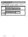
7
TROUBLESHOOTING
7-1. HOW TO CHECK THE PARTS
BRANCH BOX : PAC-AK50BC
PAC-AK51BC
PAC-AK30BC
PAC-AK31BC
PAC-AK52BC
PAC-AK32BC
Check points
Parts name
Thermistor (TH-A~E) Disconnect the connector then measure the resistance with a tester.
(At the ambient temperature 10~30)
<Gas pipe>
Normal
Abnormal
4.3k ~ 9.6k
Open or short
Linear expansion valve Disconnect the connector then measure the resistance with a tester.
(Winding temperature 20)
( LEV-A~E )
Normal
M
Red
1
Brown 2
Blue 3
Orange 4
Yellow 5
White 6
OCH508A
Abnormal
Red - White Red - Orange Brown - Yellow Brown - Blue
46 ± 4
12
Open or short
PAC-AK53BC
Linear expansion valve
(LEV) in Branch box
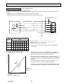
(1) Operation summary of the linear expansion valve
• Linear expansion valve open/close through stepping motor after receiving the pulse signal from the branch box controller
board.
• Valve position can be changed in proportion to the number of pulse signal.
<Connection between the branch box controller board and the linear expansion valve>
branch box controller board
DC12V
Red
1
Brown
2
:4
Blue
3
:4
:3
Orange
4
:3
:2
Yellow
5
:2
:1
White
6
:1
LEV
3
6
M
2
1
5
4
Drive circuit
Connector LEV-A
LEV-B
LEV-C
LEV-D
LEV-E
<Output pulse signal and the valve operation>
Output
(Phase)
Output
1
2
3
5
4
6
7
8
:1
ON ON OFF OFF OFF OFF OFF ON
:2
OFF ON
:3
OFF OFF OFF ON ON ON OFF OFF
:4
OFF OFF OFF OFF OFF ON ON ON
ON ON OFF OFF OFF OFF
Valve position (capacity)
Open
• When linear expansion valve operation stops, all output phase
become OFF.
• When the switch is turned on, 700 pulse closing valve signal will be
sent till it goes to A point in order to define the valve position.
(The pulse signal is being sent for about 20 seconds.)
(2) Linear expansion valve operation
Close
Opening a valve : 8 → 7 → 6 → 5 → 4 → 3 → 2 → 1 → 8
Closing a valve : 1 → 2 → 3 → 4 → 5 → 6 → 7 → 8 → 1
The output pulse shifts in above order.
• When the valve moves smoothly, there is no sound or vibration
occurring from the linear expansion valve : however, when the pulse
number moves from B to A or when the valve is locked, sound can
be heard.
No sound is heard when the pulse number moves from B to A in
case coil is burnt out or motor is locked by open-phase.
• Sound can be detected by placing the ear against the screw driver
handle while putting the screw driver to the linear expansion valve.
500 pulse
Opening a valve
all the way
Pulse number
Extra tightening (about 32 pulse)
OCH508A
13
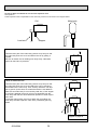
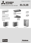
(3) How to attach and detach the coil of linear expansion valve
<Composition>
Linear expansion valve is separable into the main body and the coil as shown in the diagram below.
Main body
Coil
Lead wire
Stopper
<How to detach the coil>
Hold the lower part of the main body (shown as A) firmly so that
the main body does not move and detach the coil by pulling it
upward.
Be sure to detach the coil holding main body firmly. Otherwise
pipes can bend due to pressure.
A
<How to attach the coil>
Hold the lower part of the main body (shown as A) firmly so that
the main body does not move and attach the coil by inserting it
downward into the main body. Then securely attach the coil stopper to pipe B. (At this time, be careful that stress is not added to
lead wire and main body is not wound by lead wire.) If the stopper
is not firmly attached to pipe B, coil may be detached from the
main body and that can cause defective operation of linear expansion valve.
To prevent piping stress, be sure to attach the coil holding the
main body of linear expansion valve firmly. Otherwise pipe may
break.
B
A
Be sure to attach the
stopper to pipe B.
OCH508A
14
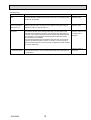
Troubleshooting
Problem
Locked expansion
valve
Check point
Corrective measure
If the linear expansion valve becomes locked and the motor is still operating, Replace the linear
expansion valve.
the motor will emit a clicking noise and will not function. This clicking noise
indicates an abnormality.
Short circuit or broken Use an all-purpose electrical meter to measure the resistance between the
different coils (red-white, red-orange, brown-yellow, brown-blue). Normal
circuit in expansion
resistance is within a range of 46 ± 4%.
valve motor coil
Replace the linear
expansion valve.
Valve does not close
completely.
In order to check the linear expansion valve, operate 1 indoor unit in the
fan mode and another in the cooling mode. Then, use the outdoor multi
controller board to operate the monitor and check the pipe temperature of
the indoor unit. The linear expansion valve should be fully closed when the
fan is operating. The temperature measured by the temperature sensor
will drop if there is any leakage.
If the measured temperature is significantly lower than that on the remote
controller, this indicates that the valve is not closed. It is not necessary to
replace the linear expansion valve if the leak of refrigerant is small and does
not cause a malfunction.
Replace the linear
expansion valve if there
is a major leak of
refrigerant.
Incorrect connection
or connection failure
Check improperly connected connector terminals and the wire colors.
Remove the connector on the controller board side and check electrical
conductance.
Continuity check of
wrong part
OCH508A
15
7-2. TEST POINT DIAGRAM
Branch box controller board
PAC-AK50BC
PAC-AK51BC
PAC-AK30BC
PAC-AK31BC
TH-A to E Connect to
Thermistor-A to E
TH-A to C for PAC-AK30/31/32BC
PAC-AK52BC
PAC-AK32BC
PAC-AK53BC
LED1
Transmission start-up state display
Start-up : LED1 blinks
(0.5sec. : ON, 0.5sec. : OFF)
Start-up completion: LED1 lights
LEV-A to E
Connect to LEV-A to E
LEV-A to C for PAC-AK30/31/32BC
LED3~5
Not used
LED2
Transmission
(Branch box/outdoor)
Reception state display
on branch box side
Branch box No.1
LED2 blinks once.
(0.1sec. : ON,
0.9sec. : OFF)
Branch box No.2
LED2 blinks twice.
(0.1sec. : ON,
0.1sec. : OFF
0.1sec. : ON,
0.7sec. : OFF)
*The blinking interval
might change when
there are changes in
states of indoor units.
TB3A to TB3E
Connect to TB3A to TB3E
(Branch box/Indoor unit connecting wire)
TB3A to TB3C for PAC-AK30/31/32BC
OCH508A
16
CN3C, CND
Connect to TB2B
(Branch box/Outdoor unit
connecting wire)
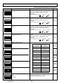
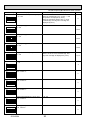
7-3. FUNCTION OF SWITCHES
<Branch box unit operation monitor function>
[When option part ‘A-Control Service Tool (PAC-SK52ST)’ is connected to branch box controller board (CNM)]
Digital indicator LED1 displays 2 digit number or code to inform operation condition and the meaning of error code by
controlling DIP SW2 on ‘A-Control Service Tool’.
Operation indicator
SW2 : Indicator change of self diagnosis
The black square (■) indicates a switch position.
SW2 setting
Unit
Explanation for display
Display detail
ON
1 2 3 4 5 6
<Digital indicator LED1 working details>
(Be sure that 1 to 6 in the SW2 are set to OFF.)
(1) Display when the power supply is ON.
When the power supply is ON, blinking displays by turns.
Wait for 2 minutes at the longest.
(2) When the display lights (Normal operation)
1The number of connected indoor units to this branch box (0 - 5)
1 second
interval
SW2
(Lighting)
ON
LED1
(Initial setting)
1 2 3 4 5 6
ON
Pipe temperature / Liquid (TH3)
– 40 - 90
– 40 - 90
(When the coil thermistor detects 0: or below, “–”
and temperature are displayed by turns.)
(Example)
When –10:;
0.5 secs. 0.5 secs. 2 secs.
1 2 3 4 5 6
:
10
Discharge temperature (TH4)
3 - 217
3 - 217
(When the discharge thermistor detects 100: or
more, hundreds digit, tens digit and ones digit are
displayed by turns.)
(Example)
When 105:;
0.5 secs. 0.5 secs. 2 secs.
ON
1 2 3 4 5 6
1
ON
:
05
Output step of outdoor FAN
0 - 15
0 - 15
Unit number of this branch box
1-2
1 or 2
* Omit the figures after the decimal fractions.
Compressor operating frequency
0 - 225
0 - 255
(When it is 100Hz or more, hundreds digit, tens
digit and ones digit are displayed by turns.
(Example)
When 125Hz;
0.5 secs. 0.5 secs. 2 secs.
1
25
Step
1 2 3 4 5 6
ON
1 2 3 4 5 6
ON
1 2 3 4 5 6
LEV-A opening pulse
0 - 500
0 - 500
(When it is 100 pulse or more, hundreds digit, tens
digit and ones digit are displayed by turns.
(Example)
When 150 pulse; 0.5 secs. 0.5 secs. 2 secs.
1
50
ON
1 2 3 4 5 6
OCH508A
17
code
display
.Hz
Pulse
LEV-B opening pulse
0 - 500
ON
1 2 3 4 5 6
LEV-C opening pulse
0 - 500
ON
1 2 3 4 5 6
LEV-D opening pulse
0 - 500
ON
1 2 3 4 5 6
LEV-E opening pulse
0 - 500
ON
The black square (■) indicates a switch position.
Unit
Explanation for display
Display detail
SW2 setting
1 2 3 4 5 6
0 - 500
(When it is 100 pulse or more, hundreds digit, tens
digit and ones digit are displayed by turns.
(Example)
When 150 pulse; 0.5 secs. 0.5 secs. 2 secs.
1
50
Pulse
0 - 500
(When it is 100 pulse or more, hundreds digit, tens
digit and ones digit are displayed by turns.
(Example)
When 150 pulse; 0.5 secs. 0.5 secs. 2 secs.
1
50
Pulse
0 - 500
(When it is 100 pulse or more, hundreds digit, tens
digit and ones digit are displayed by turns.
(Example)
When 150 pulse; 0.5 secs. 0.5 secs. 2 secs.
1
50
Pulse
0 - 500
(When it is 100 pulse or more, hundreds digit, tens
digit and ones digit are displayed by turns.
(Example)
When 150 pulse; 0.5 secs. 0.5 secs. 2 secs.
1
50
Pulse
Capacity setting indoor-A
0 - 14
ON
1 2 3 4 5 6
Capacity setting indoor-B
0 - 14
ON
1 2 3 4 5 6
Capacity setting indoor-C
0 - 14
ON
1 2 3 4 5 6
Capacity setting indoor-D
0 - 14
ON
1 2 3 4 5 6
Capacity setting indoor-E
0 - 14
ON
1 2 3 4 5 6
ON
1 2 3 4 5 6
Indoor pipe temperature / Liquid
TH2
Indoor-A
– 39 - 88
OCH508A
Code display
(Not Qj)
Rated
capacity
0
15
1
20
2
22
3
25
4
28
5
32
6
35
7
40
8
45
9
50
10
56
11
60
12
71
13
80
15
100
– 39 - 88
(When the temperature is 0: or less, “–” and
temperature are displayed by turns.)
18
Code
display
Code
display
Code
display
Code
display
Code
display
:
SW2 setting
ON
1 2 3 4 5 6
ON
1 2 3 4 5 6
ON
1 2 3 4 5 6
ON
1 2 3 4 5 6
ON
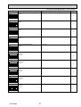
The black square (■) indicates a switch position.
Unit
Explanation for display
Display detail
Indoor pipe temperature / Liquid
TH2
Indoor-B
– 35 - 88
– 35 - 88
(When the temperature is 0: or less, “–” and
temperature are displayed by turns.)
:
Indoor pipe temperature / Liquid
TH2
Indoor-C
– 39 - 88
– 39 - 88
(When the temperature is 0: or less, “–” and
temperature are displayed by turns.)
:
Indoor pipe temperature / Liquid
TH2
Indoor-D
– 39 - 88
– 39 - 88
(When the temperature is 0: or less, “–” and
temperature are displayed by turns.)
:
Indoor pipe temperature / Liquid
TH2
Indoor-E
– 39 - 88
– 39 - 88
(When the temperature is 0: or less, “–” and
temperature are displayed by turns.)
:
LEV-1 opening pulse
0 - 500
0 - 500
Pulse
1 2 3 4 5 6
ON
LEV-2 opening pulse
0 - 500
0 - 500
Pulse
1 2 3 4 5 6
ON
LEV-3 opening pulse
0 - 500
0 - 500
Pulse
1 2 3 4 5 6
ON
LEV-4 opening pulse
0 - 500
0 - 500
Pulse
1 2 3 4 5 6
ON
LEV-5 opening pulse
0 - 500
0 - 500
Pulse
1 2 3 4 5 6
ON
Outdoor pipe temperature / 2-phase
(TH6)
– 39 - 88
– 39 - 88
(When the temperature is 0: or less, “–” and
temperature are displayed by turns.)
:
Outdoor outside temperature (TH7)
– 39 - 88
– 39 - 88
(When the temperature is 0: or less, “–” and
temperature are displayed by turns.)
:
1 2 3 4 5 6
ON
1 2 3 4 5 6
OCH508A
19
Outdoor heatsink temperature (TH8)
– 40 - 200
ON
1 2 3 4 5 6
LEV-6 opening pulse
0 - 500
ON
The black square (■) indicates a switch position.
Explanation for display
Unit
Display detail
SW2 setting
– 40 - 200
(When the temperature is 0: or less, “–” and
temperature are displayed by turns.)
(When the thermistor detects 100: or more,
hundreds digit, tens digit and ones digit are
displayed by turns.)
:
0 - 500
Pulse
1 2 3 4 5 6
LEV-7 opening pulse
0 - 500
ON
0 - 500
Pulse
1 2 3 4 5 6
LEV-8 opening pulse
0 - 500
ON
0 - 500
Pulse
1 2 3 4 5 6
High pressure o 10 (63HS)
0 - 500
ON
0 - 500
(When it is 100 or more, hundreds digit, tens
digit and ones digit are displayed by turns.)
of/f
1 2 3 4 5 6
Input current
0 - 50
ON
0 - 50
A
1 2 3 4 5 6
Indoor pipe temperature / Cond. / Eva.
TH5 Indoor-A
ON
– 39 - 88
:
1 2 3 4 5 6
Indoor pipe temperature / Cond. / Eva.
TH5 Indoor-B
ON
– 39 - 88
:
1 2 3 4 5 6
Indoor pipe temperature / Cond. / Eva.
TH5 Indoor-C
ON
– 39 - 88
:
1 2 3 4 5 6
Indoor pipe temperature / Cond. / Eva.
TH5 Indoor-D
ON
– 39 - 88
:
1 2 3 4 5 6
Indoor pipe temperature / Cond. / Eva.
TH5 Indoor-E
ON
– 39 - 88
:
1 2 3 4 5 6
OCH508A
20
ON
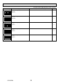
The black square (■) indicates a switch position.
Explanation for display
Unit
Display detail
SW2 setting
Branch pipe temperature
TH-A
– 39 - 88
:
1 2 3 4 5 6
ON
Branch pipe temperature
TH-B
– 39 - 88
:
1 2 3 4 5 6
ON
Branch pipe temperature
TH-C
– 39 - 88
:
1 2 3 4 5 6
ON
Branch pipe temperature
TH-D
– 39 - 88
:
1 2 3 4 5 6
ON
Branch pipe temperature
TH-E
– 39 - 88
:
1 2 3 4 5 6
ON
TH1
Indoor-A
8 - 39
8 - 39
TH1
Indoor-B
8 - 39
8 - 39
TH1
Indoor-C
8 - 39
8 - 39
TH1
Indoor-D
8 - 39
8 - 39
TH1
Indoor-E
8 - 39
8 - 39
:
1 2 3 4 5 6
ON
:
1 2 3 4 5 6
ON
:
1 2 3 4 5 6
ON
:
1 2 3 4 5 6
ON
:
1 2 3 4 5 6
OCH508A
21
Display detail
SW2 setting
ON
The black square (■) indicates a switch position.
Unit
Explanation for display
Indoor - setting temperature
16 - 31
Indoor-A
16 - 31
Indoor - setting temperature
16 - 31
Indoor-B
16 - 31
Indoor - setting temperature
16 - 31
Indoor-C
16 - 31
Indoor - setting temperature
16 - 31
Indoor-D
16 - 31
Indoor - setting temperature
16 - 31
Indoor-E
16 - 31
:
1 2 3 4 5 6
ON
:
1 2 3 4 5 6
ON
:
1 2 3 4 5 6
ON
:
1 2 3 4 5 6
ON
:
1 2 3 4 5 6
OCH508A
22
8
DISASSEMBLY PROCEDURE
PAC-AK50BC
PAC-AK30BC
PAC-AK51BC
PAC-AK31BC
PAC-AK52BC
PAC-AK32BC
PAC-AK53BC
Note:
1. Before disassembling/servicing the branch box, be sure to power off the outdoor unit.
2. Be careful of dropping of the panel or controller board during the service.
3. When servicing the parts associated with refrigerant, recover refrigerant in advance.
4. Be sure to practice non-oxidation welding.
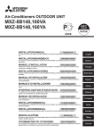
PHOTOS
OPERATING PROCEDURE
1. Removing the controller cover and under panel
Photo 1
(1) Remove 3 controller cover fixing screws (4 o 10) to detach
the cover. (See Photo 1.)
(2) Remove 6 under panel fixing screws (4 o 10) to remove
the panel. (See Photo 1.)
Under panel fixing screws
Controller cover fixing screws
2. Removing the drain pan
(1) Remove the under panel. (See Photo 1.)
(2) Remove the drain hose.
(3) Incline the side of the drain pan that faces the piping to
remove the pan.
* When removing the drain pan, be careful with
remaining water on the pan.
Also, be careful not to make cracks on the pan.
Photo 2
Drain pan
3. Removing the thermistors (TH-A–E)
(1) Remove the controller cover. (See Photo 1.)
(2) Remove the under panel. (See Photo 1.)
(3) Pull out the thermistors, TH-A–E, from the sensor holders
mounted on the gas pipe. (See Photo 3.)
(4) Pull out those thermistors through the U-shaped hole to
the board side.
(5) Loosen the side clamps of the board and disconnect the
connectors on the board.
Photo 3
Sensor holder
U-shaped hole
OCH508A
23
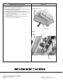
PHOTOS
OPERATING PROCEDURE
4. Removing the LEV coil (LEV-A–E)
(1) Remove the controller cover. (See Photo 1.)
(2) Remove the under cover. (See Photo 1.)
(3) Remove 4 separator fixing screws (4 o 10) in the side of
the branch box. (See Photo 4.)
(4) Tilt the separator to the board side. (See Photo 4.)
(5) Loosen the side clamps of the board and disconnect the
connectors on the board.
(6) Pull out the lead wire through the U-shaped hole.
(See Photo 3.)
(7) Cut the band that fixes the lead wire to pull out the
LEV coil (LEV-A–E). (See Photo 5.)
Photo 4
Separator fixing screws
Separator
Photo 5
Separator
LEV coil
Band
HEAD OFFICE : TOKYO BLDG., 2-7-3, MARUNOUCHI, CHIYODA-KU, TOKYO100-8310, JAPAN
cCopyright 2011 MITSUBISHI ELECTRIC CORPORATION
Distributed in Apr. 2013 No.OCH508 REVISED EDITION-A
Distributed in Jul. 2011 No.OCH508
Made in Japan
New publication, effective Apr. 2013
Specifications are subject to change without notice.