1
HFC
utilized
R410A
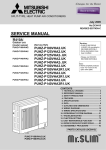
SPLIT-TYPE, HEAT PUMP AIR CONDITIONERS
March 2015
No. OCH574
TECHNICAL & SERVICE MANUAL
[Model Name]
<Branch box>
PAC-MK50BC
PAC-MK30BC
[Service Ref.]
REVISED EDITION-A
Revision:
• Corrected some errors in "7-1.
PAC-MK50BC
PAC-MK30BC
(Indispensable optional parts for
PUMY-P112/125/140VKM1 and PUMY-P112/125/140YKM1)
HOW TO CHECK THE PARTS" in REVISED EDITION-A.
•Some descriptions have been
modified.
• Please void OCH574.
Note:
•This service manual describes
technical data of branch box. As
for indoor units and outdoor unit,
refer to its service manual.
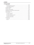
CONTENTS
1. SAFETY PRECAUTION ······································· 2
2. OVERVIEW OF UNIT ··········································· 5
3. SPECIFICATIONS ················································ 8
4. OUTLINES AND DIMENSIONS ··························· 9
5. WIRING DIAGRAM ············································· 10
6. NECESSARY CONDITIONS FOR SYSTEM CONSTRUCTION··············11
7. TROUBLESHOOTING ········································ 15
8. DISASSEMBLY PROCEDURE ··························· 24
BRANCH BOX
PARTS CATALOG (OCB574)
1
SAFETY PRECAUTION
1-1. ALWAYS OBSERVE FOR SAFETY
Before obtaining access to terminal, all supply
circuit must be disconnected.
1-2. CAUTIONS RELATED TO NEW REFRIGERANT
Cautions for units utilizing refrigerant R410A
Use new refrigerant pipes.
Make sure that the inside and outside of refrigerant piping is clean and it has no contaminants
such as sulfur, oxides, dirt, shaving particles, etc,
which are hazard to refrigerant cycle.
In addition, use pipes with specified thickness.
Contamination inside refrigerant piping can cause deterioration of refrigerant oil, etc.
Store the piping indoors, and both ends of the
piping sealed until just before brazing.
(Leave elbow joints, etc. in their packaging.)
Do not use refrigerant other than R410A.
If other refrigerant (R22, etc.) is used, chlorine in refrigerant can cause deterioration of refrigerant oil, etc.
Use a vacuum pump with a reverse flow check
valve.
Vacuum pump oil may flow back into refrigerant cycle and
that can cause deterioration of refrigerant oil, etc.
Use the following tools specifically designed for
use with R410A refrigerant.
The following tools are necessary to use R410A refrigerant.
Gauge manifold
Charge hose
Gas leak detector
Torque wrench
If dirt, dust or moisture enters into refrigerant cycle, that can
cause deterioration of refrigerant oil or malfunction of compressor.
The refrigerant oil applied to flare and flange
connections must be ester oil, ether oil or
alkylbenzene oil in a small amount.
If large amount of mineral oil enters, that can cause deterioration of refrigerant oil, etc.
Charge refrigerant from liquid phase of gas
cylinder.
Tools for R410A
Flare tool
Size adjustment gauge
Vacuum pump adaptor
Electronic refrigerant
charging scale
Handle tools with care.
If dirt, dust or moisture enters into refrigerant cycle, that can
cause deterioration of refrigerant oil or malfunction of compressor.
If the refrigerant is charged from gas phase, composition
change may occur in refrigerant and the efficiency will be
lowered.
Do not use a charging cylinder.
Use the specified refrigerant only.
Ventilate the room if refrigerant leaks during
operation. If refrigerant comes into contact with
a flame, poisonous gases will be released.
Never use any refrigerant other than that specified.
Doing so may cause a burst, an explosion, or fire when the
unit is being used, serviced, or disposed of.
Correct refrigerant is specified in the manuals and on the
spec labels provided with our products.
We will not be held responsible for mechanical failure,
system malfunction, unit breakdown or accidents caused
by failure to follow the instructions.
OCH531A
If a charging cylinder is used, the composition of refrigerant will change and the efficiency will be lowered.
2
[1] Cautions for service
(1) Perform service after recovering the refrigerant left in unit completely.
(2) Do not release refrigerant in the air.
(3) After completing service, charge the cycle with specified amount of refrigerant.
(4) When performing service, install a filter drier simultaneously.
Be sure to use a filter drier for new refrigerant.
[2] Additional refrigerant charge
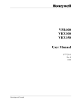
When charging directly from cylinder
· Check that cylinder for R410A on the market is a syphon type.
· Charging should be performed with the cylinder of syphon stood vertically. (Refrigerant is charged from liquid phase.)
Unit
Gravimeter
[3] Service tools
(1) Use the below service tools as exclusive tools for R410A refrigerant.
No.
Tool name
1
Gauge manifold
2
Charge hose
3
4
5
6
Electronic scale
Gas leak detector
Adaptor for reverse flow check
Refrigerant charge base
7
Refrigerant cylinder
8
Refrigerant recovery equipment
OCH531A
·
·
·
·
·
Specifications
Only for R410A
Use the existing fitting specifications. (UNF1/2)
Use high-tension side pressure of 5.3MPa·G or over.
Only for R410A
Use pressure performance of 5.09MPa·G or over.
· Use the detector for R134a, R407C or R410A.
· Attach on vacuum pump.
· Only for R410A · Top of cylinder (Pink)
· Cylinder with syphon
3
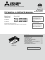
(2) Cautions for refrigerant piping work
New refrigerant R410A is adopted for replacement inverter series. Although the refrigerant piping work for R410A is same
as for R22, exclusive tools are necessary so as not to mix with different kind of refrigerant. Furthermore as the working
pressure of R410A is 1.6 times higher than that of R22, their sizes of flared sections and flare nuts are different.
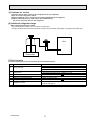
1 Thickness of pipes
Because the working pressure of R410A is higher compared to R22, be sure to use refrigerant piping with thickness
shown below. (Never use pipes of 0.7 mm or below.)
Diagram below: Piping diameter and thickness
Nominal
Thickness (mm)
Outside
dimensions (in) diameter (mm)
R410A
R22
0.8
0.8
6.35
1/4
0.8
0.8
9.52
3/8
0.8
0.8
12.70
1/2
1.0
1.0
15.88
5/8
—
1.0
19.05
3/4
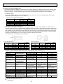
2 Dimensions of flare cutting and flare nut
The component molecules in HFC refrigerant are smaller compared to conventional refrigerants. In addition to that,
R410A is a refrigerant, which has higher risk of leakage because of its working pressure higher than that of other refrigerants. Therefore, to enhance airtightness and strength, flare cutting dimension of copper pipe for R410A has been specified separately from the dimensions for other refrigerants as shown below. The dimension B of flare nut for R410A also
has partly been changed to increase strength as shown below. Set copper pipe correctly referring to copper pipe flaring
dimensions for R410A below. For 1/2” and 5/8” inch pipes, the dimension B changes.
Use torque wrench corresponding to each dimension.
Dimension A
Dimension B
Flare cutting dimensions
Nominal
Outside
diameter (mm)
dimensions (in)
6.35
1/4
9.52
3/8
12.70
1/2
15.88
5/8
19.05
3/4
Dimension A ( +0
-0.4 ) (mm)
R410A
R22
9.0
9.1
13.0
13.2
16.2
16.6
19.4
19.7
—
23.3
Flare nut dimensions
Nominal
Outside
dimensions (in) diameter (mm)
6.35
1/4
9.52
3/8
12.70
1/2
15.88
5/8
19.05
3/4
Dimension B (mm)
R410A
R22
17.0
17.0
22.0
22.0
24.0
26.0
27.0
29.0
—
36.0
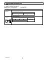
3 Tools for R410A (The following table shows whether conventional tools can be used or not.)
R410A tools
Can R22 tools be used? Can R407C tools be used?
Tool exclusive for R410A
Tool exclusive for R410A
Tool for HFC refrigerant
Tool exclusive for R410A
Tool exclusive for R410A
Ester oil and alkylbenzene
Ester oil:
Alkylbenzene oil: minimum amount
oil (minimum amount)
Prevent compressor malfunction Tool exclusive for R410A
Safety charger
when charging refrigerant by
spraying liquid refrigerant
Prevent gas from blowing out Tool exclusive for R410A
Charge valve
when detaching charge hose
Vacuum drying and air
Tools for other refrigerants can
Vacuum pump
(Usable if equipped
(Usable if equipped
with adopter for reverwith adopter for reverpurge
be used if equipped with adopse flow)
se flow)
ter for reverse flow check
Flaring work of piping
Tools for other refrigerants
Flare tool
(Usable by adjusting
(Usable by adjusting
can be used by adjusting
flaring dimension)
flaring dimension)
flaring dimension
Bend the pipes
Tools for other refrigerants can be used
Bender
Tools for other refrigerants can be used
Cut the pipes
Pipe cutter
Tools for other refrigerants can be used
Welder and nitrogen gas cylinder Weld the pipes
Tools for other refrigerants can be used
Refrigerant charging scale Refrigerant charge
Vacuum gauge or thermis- Check the degree of vacuum. (Vacuum Tools for other refrigerants
valve prevents back flow of oil and refri- can be used
tor vacuum gauge and
gerant to thermistor vacuum gauge)
vacuum valve
Refrigerant charge
Charging cylinder
Tool exclusive for R410A
: Prepare a new tool. (Use the new tool as the tool exclusive for R410A.)
: Tools for other refrigerants can be used under certain conditions.
: Tools for other refrigerants can be used.
Tools and materials
Gauge manifold
Charge hose
Gas leak detector
Refrigerant recovery equipment
Refrigerant cylinder
Applied oil
OCH531A
Use
Air purge, refrigerant charge
and operation check
Gas leak check
Refrigerant recovery
Refrigerant charge
Apply to flared section
4
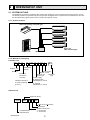
2
OVERVIEW OF UNIT
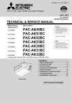
2-1. SYSTEM OUTLINE
The additional connection of the Branch Box together with employment of the compact trunk-looking outdoor unit can
successfully realizes a long distance piping for big houses. Equipped with a microprocessor, the Branch Box can translate the transmission signal of indoor units to achieve the optimum control.
2-1-1. System example
Indoor unit (Ceiling concealed type)
Indoor unit
(Wall mounted type)
Outdoor unit
Branch Box
2-1-2. Method for identifying
■ Outdoor unit
PU M Y - P 125 Y K M 1 - BS
Outdoor unit
Refrigerant
R410A
Sub number
M-NET control
Outdoor unit
Salt proof
model type
type
Power supply
MULTI-S
Frequency
conversion
controller
V: Single phase
220/230/240 V, 50 Hz
Indicates equivalent
to Cooling capacity
(k cal/ h)
Y: 3-phase
380/400/415 V, 50 Hz
■ Branch box
Symbol of factory
P A C – MK
5 0 BC
Branch box (Controller)
Model type
(Indispensable)
Optional parts
OCH531A
Number of branches
5 : 5 branches
3 : 3 branches
5
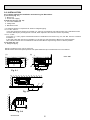
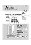
2-2. INSTALLATION
2-2-1. Space required for Installation and servicing for Branch box.
(1) Front View (Fig. 2-1)
A Branch box
B On the side of piping
(2) Side View (Fig. 2-2, Fig. 2-3)
C For indoor installations
D Ceiling board
E Maintenance hole
*1: A minimum 350 mm is required for 90° bends in refrigerant piping.
*2: A is “Min. 200 mm”.
In the case of less than 200 mm (for example A is 100 mm), the exchange work of Branch box from a maintenance hole
becomes difficult (Only exchange work of a PCB, linear expansion valve coils and sensors is possible).
*3: B is “ □ 600”.
In the case of “ □ 450”, prepare a maintenance hole at a PCB side as it is shown in Fig. 2-3, and “Min. 300 mm” is needed
as distance A.
In the case of less than 300 mm (for example A is 100 mm), the exchange work of Branch box, linear expansion
valve coils and sensors from a maintenance hole becomes difficult. Only exchange work of a PCB is possible.
(3) Top View (Fig. 2-4)
G Refrigerant piping
NOTE1: The branch box is only for indoor use.
NOTE2: Please attach the special optional cover (PAC-AK350CVR-E) to install branch box in the outdoors.
(2)
C
30
(1)
170
A
*2
B
50
*1
450
278
250
250
D
180-200
Fig. 2-1
250
E
*3
Fig. 2-2
E
D
450
Fig. 2-3
(3)
G
Min. 250
Fig. 2-4
OCH531A
6
unit : mm
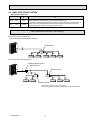
2-3. SIMPLIFIED PIPING SYSTEM
Piping connection size
A
Liquid
(mm)
{9.52
Gas
(mm)
{15.88
B
The piping connection size differs according to the type and capacity of indoor units.
Match the piping connection size of branch box with indoor unit.
If the piping connection size of branch box does not match the piping connection size of
indoor unit, use optional different-diameter (deformed) joints to the branch box side.
(Connect deformed joint directly to the branch box side.)
Flare connection employed. (No brazing!)
■ In case of using 1-branch box
Flare connection employed (No brazing)
Branch box
A
B
B
B
B
B
■ In case of using 2-branch boxes
2 branches pipe (joint)
: optional parts
A
A
Branch box #1
A
B
B
B
B
B
Branch box #2
■ Installation procedure (2 branch pipe (joint))
Refer to the installation manuals of MSDD-50AR-E and MSDD-50BR-E.
OCH531A
7
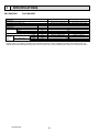
3
SPECIFICATIONS
PAC-MK50BCPAC-MK30BC
Model Name
Connectable number of indoor units
Power supply (from outdoor unit)
Input
Running current
External finish
Dimensions
Width
Depth
Height
Weight
Piping
connection
(Flare)
Branch (indoor side)*
Main (outdoor side)
kW
A
Liquid
Gas
Liquid
Gas
mm
mm
mm
kg
mm
mm
mm
mm
PAC-MK50BC
PAC-MK30BC
Maximum 5
Maximum 3
Single phase, 220/230/240V, 50Hz, Single phase, 220V, 60Hz
0.003
0.05 (Max. 6)
Galvanized sheets
450
280
170
7.4
6.7
[6.35 O 5 {A,B,C,D,E}
[6.35 O 3 {A,B,C}
[9.52 O 4 {A,B,C,D}, [12.7 o 1{E}
[9.52 O 3 {A,B,C}
[9.52
[15.88
* The piping connection size differs according to the type and capacity of indoor units. Match the piping connection size for indoor
and branch box. If the piping connection size of branch box does not match the piping connection size of indoor units, use
optional different-diameter (deformed) joints to the branch box side. (Connect deformed joint directly to the branch box side.)
OCH531A
8
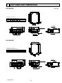
4
OUTLINES AND DIMENSIONS
unit: mm
PAC-MK50BC
SUSPENSION BOLT PITCH
402
SUSPENSION BOLT PITCH
320
SUSPENSION BOLT : W3/8(M10)
REFRIGERANT PIPE FLARED CONNECTION
TO OUTDOOR UNIT
A
B
C
D
E
LIQUID PIPE 1/4F 1/4F 1/4F 1/4F 1/4F 3/8F
GAS PIPE
3/8F 3/8F 3/8F 3/8F 1/2F 5/8F
24
12
450
67
90
TO INDOOR UNIT
96
72
280
87
70
TERMINAL BLOCK
TO INDOOR UNIT
5-ELECTRIC WIRE INLET
65
112
A
A
25
25
25
25
70
70
CONTROL COVER
25
70
70
TO OUTDOOR UNIT
SERVICE PANEL
(for LEV,THERMISTOR)
TB3E
TB2B
170
B
TB3D
B
C
TB3C
C
D
TB3B
D
E
TB5
E
TB3A
47
83
TERMINAL BLOCK
TO M-NET UNIT
40
TERMINAL BLOCK
TO OUTDOOR UNIT
BUSH
PAC-MK30BC
402
SUSPENSION BOLT PITCH
SUSPENSION BOLT PITCH
320
SUSPENSION BOLT : W3/8(M10)
REFRIGERANT PIPE FLARED CONNECTION
A
B
C
LIQUID PIPE 1/4F 1/4F 1/4F
GAS PIPE
3/8F 3/8F 3/8F
24
TO OUTDOOR UNIT
3/8F
5/8F
12
452
90
209
72
TO INDOOR UNIT
280
83
87
TERMINAL BLOCK
TO M-NET UNIT
40
TERMINAL BLOCK
TO INDOOR UNIT
5-ELECTRIC WIRE INLET
70
65
25
25
25
112
TB2B
170
A
A
CONTROL COVER
CAP
70
OCH531A
TB3C
B
B
TB5
C
C
TB3B
TB3A
47
CAP
96
TO OUTDOOR UNIT
SERVICE PANEL
(for LEV.THERMISTOR)
70
9
BUSH
TERMINAL BLOCK
TO OUTDOOR UNIT
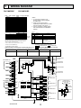
5
WIRING DIAGRAM
PAC-MK50BCPAC-MK30BC
Note : " PAC - MK30 . 50BC " is only for R410A.
SYMBOL
B.C.
F1
<B.C.>
F2~F4 <B.C.>
SW1 <B.C.>
SW4 <B.C.>
SW5 <B.C.>
CNM <B.C.>
LED1,2 <B.C.>
LEV-A~E
TH-A~E
TB2B
TB5
TB3A~E <B.C.>
SW11 <B.C.>
SW12 <B.C.>
NAME
Branch box controller board
Fuse <T6.3AL 250V>
Fuse <T10AL 250V>
Switch for indoor unit connection *1
Switch for mode selection
Not in use
Connector <Connection for service>
Light emitting diode *2
Linear expansion valve *3
Thermistor <Gas pipe> *3
Terminal block <To Power Supply>
Terminal block <Transmission>
Terminal block To indoor unit-A~E *3
Address Setting 1s DIGIT
Address Setting 10ths DIGIT
<Note>
1. At servicing for outdoor unit,
always follow the wiring diagram
of outdoor unit.
2. When work to supply power
separately to Branch box and outdoor
units are applied, refer to Fig. 1.
3. For the connection method, please
refer to the Branch box Installation
Manual.
*1 SW1 setting
OFF
ON
NOT CONNECT CONNECT
SW1-1
INDOOR UNIT-A
NOT CONNECT CONNECT
SW1-2
INDOOR UNIT-B
NOT CONNECT CONNECT
SW1-3
INDOOR UNIT-C
PAC-MK
NOT CONNECT CONNECT
SW1-4
INDOOR UNIT-D
50BC only
NOT CONNECT CONNECT
SW1-5
INDOOR UNIT-E
SW1-6
NO USE
After each indoor unit is connected to the outdoor unit, turn on
the switch corresponding to each indoor unit. For example,
when the indoor units are connected to INDOOR UNIT-A
and C, turn SW1-1 and SW1-3 to on.
• start-up
Meaning
Mark
LED 1 Main power supply
LED 2
• normal operating
Meaning
Mark
LED 1 Main power supply
LED 2 Total number of
indoor units
*2 LED on Branch box controller board for service
Function
Main power supply (220/230/240V)
Power on → Lamps are lit
Function
Lamp is lit
Blink depend on the total number
<example> The total number is 2
1 Blink 2 times.
2 Turn off for three sec.
3 Repeat 1 to 2.
<Symbols used in wiring diagram>
: Terminal block,
: Connector
<Combination of indoor units>
: Dip switch (■(black square) indicates
Enter the location of combined indoor units with model name in each
a switch position)
blank below because it is necessary for service and maintenance.
*3 D and E for PAC-MK50BC only.
Indoor unit-A
5
LEV-E
(GRN)
1
5
LEV-D
(BLK)
1
LEV-C M
5
LEV-C
(BLU)
1
LEV-B M
5
LEV-B
(RED)
1
LEV-A M
5
LEV-A
(WHT)
1
2 TH-E
1 (GRN)
TH-D
tº
F4
10A 250V
SW1
TB3D
ON
OFF
ON
OFF
123456
1 2 3 4 5 6 7 8 9 10
SW5
SW12 SW11
9
0 1
7 8
5 6
2 TH-A
1 (WHT)
9
0 1
F3
10A 250V
ON
OFF
10ths 1s
DIGIT DIGIT
123456
TB3B
F2
10A 250V
LED1
LED2
CNM
(WHT)
14
TB1
S3
S2
S1
S3
S2
S1
TB3A
1
S3
S2
S1
S3
S2
S1
TB3C
tº
OCH531A
RED
BLU
TB2B
(SHIELD)
L
N
TO OUTDOOR UNIT
TO ANOTHER
BRANCH BOX
2 3
TH-A
tº
(SHIELD)
TO ANOTHER
BRANCH BOX
1
SW4
2 3
TH-B
TO OUTDOOR UNIT
DC24-30V
(PAC-MK50BC only)
2 TH-C
1 (BLU)
2 TH-B
1 (RED)
TB5
M1
M2
S
3
TB3E
2 TH-D
1 (BLK)
tº
Indoor unit-E
M-NET
CN3M
1 2 3 (BLU)
tº
TH-C
CND
(BLK)
–
+
4
TH-E
F1
6.3A 250V
7 8
LEV-D M
(PAC-MK50BC only)
Indoor unit-D
B.C.
5 6
LEV-E M
Indoor unit-C
BLU
BLU
4
(PAC-MK50BC only)
Indoor unit-B
S3
S2
S1
10
TO
INDOOR UNIT-E
Fig. 1
POWER SUPPLY
220/ 230/ 240V 50Hz
220V 60Hz
TO
INDOOR UNIT-D
TO
INDOOR UNIT-C
TO
INDOOR UNI T-B
TO
INDOOR UNIT-A
CIRCUIT
BREAKER
RED
BLU
TB2B
L
N
PULL BOX
TO ANOTHER
BRANCH BOX
For centralized
management
78
78
901
901
Address SW
061
Outdoor unit
A
78
MA remote
controller
MA remote
controller
901
Address SW
901
C
Branch box
001
A-control
Indoor unit
C
(003)
B
A-control
Indoor unit
B
(002)
City Multi
Indoor unit
011
MA remote
controller
A-control
Indoor unit
A
(001)
Signal line
4
For Branch box/ City Multi indoor unit
⑤ M-NET remote controller cannot be connected
with a system constructed via branch box.
④ Make sure that the wiring between the
branch box and indoor unit is properly
done, matching with the piping connection.
③ Outdoor unit has no 100ths digit switch.
The address automatically become "100"
if it is set as "01–50".
Outdoor unit ............ 051–100
Branch box ............... 001–046
City Multi .................. 001–050
② Set addresses :
① M-NET cable shielding wire must
be connected to each refrigerant
system (outdoor and branch box).
2
901
78
78
78
901
78
78
Address SW
901
Address SW
901
5
6
E
WL-RC
4
WL-RC
3
A-control
Indoor unit
E
(005)
D
2
A-control
Indoor unit
D
(004)
1
SW1
ON
City Multi
Indoor unit
012
78
5
901
901
901
MA remote
controller
A-control
Indoor unit
A
(006)
A
901
Address SW
Address SW
City Multi
Indoor unit
013
Piping
78
1
78
78
901
78
78
901
114
WL-RC
(007)
A-control
Indoor unit
B
B
901
901
2
3
C
5
6
164
901
901
Address SW
M-NET
remote
controller
WL-RC
A-control
Indoor unit
C
(008)
4
City Multi
Indoor unit
014
1
SW1
ON
Branch box
006
Address SW
M-NET
remote
controller
78
For Branch box/ City Multi indoor unit
M-NET cable
78
901
901
901
Address SW
901
Address SW
78
Piping
MA remote
controller
City Multi
Indoor unit
009
901
901
Address SW
78
051
78
78
Outdoor unit
78
78
78
For centralized
management
78
456
23
23
456
456
23
23
456
456
23
23
456
456
23
23
456
23
456
456
23
23
456
23
456
11
23
456
456
23
23
456
456
23
MA remote
controller
City Multi
Indoor unit
010
901
901
Address SW
City Multi
Indoor unit
015
78
456
23
23
456
456
23
23
456
23
456
456
456
23
456
23
456
23
456
OCH531A
23
23
78
6
NECESSARY CONDITIONS FOR SYSTEM CONSTRUCTION
6-1. TRANSMISSION SYSTEM SETUP
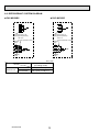
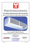
6-2. REFRIGERANT SYSTEM DIAGRAM
■ PAC-MK50BC
■ PAC-MK30BC
E
D
C
B
A
C
B
A
Thermistor (TH-A–E)
(Gas pipe temperature)
Thermistor (TH-A–C)
(Gas pipe temperature)
LEV A–E
(Linear expansion valve)
Strainer
#100
LEV A–C
(Linear expansion valve)
Strainer
#100
Strainer
#100
Strainer
#100
Capillary
tube
Capillary
tube
unit : mm
Capillary tube behind LEV
(in cooling mode)
PAC-MK50BC
([4 o [3.0 o L130) o 5
PAC-MK30BC
([4 o [3.0 o L130) o 3
Branch box
OCH531A
12
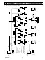
6-3. TYPICAL CONTROL SYSTEM
Branch Box
OC
(51)
L1
TB3
TB7
M1 M2 S M1 M2 S
TB5
M1
M2
S
L5
A
L2
OC
(53)
L6
A
A
M1 M2 S
Power
Supply
Unit
System
controller
Branch Box
TB5
M1
M1 M2 S
L7
TB3A
S1
S2
S3
A-IC
(01)
TB15
1
2
A
B
MA-RC
TB3B
S1
S2
S3
TB3A
S1
S2
S3
A-IC
(02)
TB15
1
2
A
B
MA-RC
TB3C
S1
S2
S3
TB3A
S1
S2
S3
A-IC
(03)
TB15
1
2
A
B
MA-RC
TB3D
S1
S2
S3
TB3A
S1
S2
S3
A-IC
(04)
WL-RC
TB3E
S1
S2
S3
TB3A
S1
S2
S3
A-IC
(05)
WL-RC
TB3A
S1
S2
S3
TB3A
S1
S2
S3
A-IC
(06)
TB3B
S1
S2
S3
TB3A
S1
S2
S3
A-IC
(07)
WL-RC
TB3C
S1
S2
S3
TB3A
S1
S2
S3
A-IC
(08)
WL-RC
TB5
M1
M2
S
M-IC
(09)
TB5
M1
M2
S
M-IC
(10)
OC : Outdoor unit
M-IC : M-NET Control indoor unit (City Multi indoor unit)
A-IC : A-control indoor unit (M, P, S series indoor unit)
MA-RC : MA Remote controller
WL-RC : Wireless Remote controller
TB7
TB3
M1 M2 S
TB3A
S1
S2
S3
M2
S
24 V DC
M1 M2 S
L3
A: Shielded wire
( ): Address example
TB15
1
2
A
B
MA-RC
TB15
1
2
A
B
MA-RC
TB15
1
2
A
B
MA-RC
L4
IMPORTANT:
Make sure that the current leakage breaker is one compatible with higher
harmonics.
Always use a current leakage breaker that is compatible with higher
harmonics as this unit is equipped with an inverter.
The use of an inadequate breaker can cause the incorrect operation of
inverter.
Longest length via outdoor units:
L1 + L2 + L3 + L4 + L5 500 m (1640 ft.) (1.25 mm2 or more)
Longest transmission cable length
L1 + L2, L3, L3 + L4, L5 200 m (656 ft.) (1.25 mm2 or more)
(1) Difference between display and operation
1 When operating the system using the system controller or the ME remote controller, details of those operations will not
appear on the display of the wireless remote controller.
2 The set temperature range is different in the wireless remote controller that comes with room air conditioner, and the ME
remote controller or the system controller. The room air conditioner has a wider range. If the target temperature is set to
below 17:[63-F] or less, or 30:[86-F] or more by the wireless remote controller that comes with room air conditioner, the
temperature displayed on the ME remote controller or the system controller may be converted to their maximum/minimum
set temperature. For instance, when HEAT operation at 16:[61-F] is set at the room air conditioner, the ME remote
controller or the system controller may display 17:[63-F].
3 When the DRY mode is set with the wireless remote controller, the room air conditioner automatically set the optimum
target temperature. The ME remote controller or the system controller will display the target temperature as a set
temperature.
4 When the DRY mode is set with the ME remote controller, or the system controller, the room air conditioner performs the
DRY mode control operation according to the temperature set with the ME remote controller or the system controller.
(2) Timer operation
1 Timer operation should be set using only one controller from the remote controller that comes with the room air conditioner,
the system controller, the MA remote controller, or the ME remote controller. If more than one controller is used to set the
timer at the same time, the timer will not function properly.
2 When the timer is set with the wireless remote controller; the ME remote controller or the system controller will not show
the timer display.
3 The timer set with the ME remote controller or the system controller will not be cancelled with the wireless remote controller.
(3) Manual operation prohibition
1 When the manual operation (ON/OFF, set temperature, or operation mode) is prohibited with the system controller, the
command to perform the prohibited operation will not be accepted from the wireless remote controller that comes with the
room air conditioner. The operation partially enabled by the system controller can be operated with the wireless remote
controller. Regardless of whether the operation is disabled or enabled, three short beeps will sound when the signal is sent
from the wireless remote controller.
(4) Trouble
1 If the MA remote controller, the ME remote controller, or the system controller shows the abnormal indication, clear it by
stopping the operation with one of the followings: the MA remote controller, the ME remote controller, the system controller,
or the wireless remote controller.
(Abnormal indication of the air conditioner could be recovered automatically, but that of the MA remote controller, the ME
remote controller, or the system controller cannot be recovered unless the operation is stopped.)
OCH531A
13
(5) Group setting
1 MA group or M-NET group setting cannot be set.
(6) Restricted functions
The following functions of system controller cannot be used.
• DIDO controller (Interlock with the air conditioner)
• Fan control of energy saving control or peak cut control function
• Air conditioning charge [TG-2000A]
• Set temperature range limiting function
• Operation mode changeover limit (season changing) [PAC-SF44SRA]
• Dual set point function
OCH531A
14
7
TROUBLESHOOTING
7-1. HOW TO CHECK THE PARTS
BRANCH BOX : PAC-MK50BC
PAC-MK30BC
Check points
Parts name
Thermistor (TH-A–E) Disconnect the connector then measure the resistance with a tester.
(At the ambient temperature 10 to 30:)
<Gas pipe>
Normal
Abnormal
4.3 to 9.6k"
Open or short
Linear expansion valve Disconnect the connector then measure the resistance with a tester.
(Winding temperature 20:)
( LEV-A–E )
Normal
M
Red
Blue
1
2
Orange
3
Yellow
4
White
5
OCH531A
Abnormal
Red - White Red - Orange Red - Yellow Red - Blue
46 ± 4"
15
Open or short
Linear expansion valve
(LEV) in Branch box
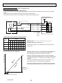
(1) Operation summary of the linear expansion valve
• Linear expansion valve open/close through stepping motor after receiving the pulse signal from the branch box controller
board.
• Valve position can be changed in proportion to the number of pulse signal.
<Connection between the branch box controller board and the linear expansion valve>
branch box controller board
12V DC
LEV
5
M
1
1
4
3
Drive circuit
Red
1
[4
Blue
2
[4
[3
Orange
3
[3
[2
Yellow
4
[2
[1
White
5
[1
2
Connector LEV-A
LEV-B
LEV-C
LEV-D
LEV-E
<Output pulse signal and the valve operation>
Output
(Phase)
Output
1
2
3
5
4
6
7
8
[1
ON ON OFF OFF OFF OFF OFF ON
[2
OFF ON
[3
OFF OFF OFF ON
[4
OFF OFF OFF OFF OFF ON ON ON
ON ON OFF OFF OFF OFF
ON ON OFF OFF
Valve position (capacity)
C
Open
• When linear expansion valve operation stops, all output phases
become OFF.
• When the switch is turned on, 700 pulse closing valve signal will be
sent till it goes to A point in order to define the valve position.
(The pulse signal is being sent for about 20 seconds.)
(2) Linear expansion valve operation
Close
Opening a valve : 8 → 7 → 6 → 5 → 4 → 3 → 2 → 1 → 8
Closing a valve : 1 → 2 → 3 → 4 → 5 → 6 → 7 → 8 → 1
The output pulse shifts in above order.
• When the valve moves smoothly, there is no sound or vibration
occurring from the linear expansion valve : however, when the pulse
number moves from B to A or when the valve is locked, sound can
be heard.
No sound is heard when the pulse number moves from B to A in
case coil is burnt out or motor is locked by open-phase.
• Sound can be detected by placing the ear against the screw driver
handle while putting the screw driver to the linear expansion valve.
500 pulse
Opening a valve
all the way
A
B
Pulse number
Extra tightening (about 32 pulse)
OCH531A
16
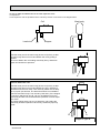
(3) How to attach and detach the coil of linear expansion valve
<Composition>
Linear expansion valve is separable into the main body and the coil as shown in the diagram below.
Main body
Coil
Lead wire
Stopper
<How to detach the coil>
Hold the lower part of the main body (shown as A) firmly so that
the main body does not move and detach the coil by pulling it
upward.
Be sure to detach the coil holding main body firmly. Otherwise
pipes can bend due to pressure.
A
<How to attach the coil>
Hold the lower part of the main body (shown as A) firmly so that
the main body does not move and attach the coil by inserting it
downward into the main body. Then securely attach the coil stopper to pipe B. (At this time, be careful that stress is not added to
lead wire and main body is not wound by lead wire.) If the stopper
is not firmly attached to pipe B, coil may be detached from the
main body and that can cause defective operation of linear expansion valve.
To prevent piping stress, be sure to attach the coil holding the
main body of linear expansion valve firmly. Otherwise pipe may
break.
B
A
Be sure to attach the
stopper to pipe B.
OCH531A
17
Troubleshooting
Problem
Locked expansion
valve
Check point
Corrective measure
If the linear expansion valve becomes locked and the motor is still operating, Replace the linear
expansion valve.
the motor will emit a clicking noise and will not function. This clicking noise
indicates an abnormality.
Short circuit or broken Use an all-purpose electrical meter to measure the resistance between the
different coils (red-white, red-orange, brown-yellow, brown-blue). Normal
circuit in expansion
resistance is within a range of 46" ± 4%.
valve motor coil
Replace the linear
expansion valve.
Valve does not close
completely.
In order to check the linear expansion valve, operate 1 indoor unit in the
fan mode and another in the cooling mode. Then, use the outdoor multi
controller board to operate the monitor and check the pipe temperature of
the indoor unit. The linear expansion valve should be fully closed when the
fan is operating. The temperature measured by the temperature sensor
will drop if there is any leakage.
If the measured temperature is significantly lower than that on the remote
controller, this indicates that the valve is not closed. It is not necessary to
replace the linear expansion valve if the leak of refrigerant is small and does
not cause a malfunction.
Replace the linear
expansion valve if there
is a major leak of
refrigerant.
Incorrect connection
or connection failure
1 Check improperly connected connector terminals and the wire colors.
2 Remove the connector on the controller board side and check electrical
conductance.
Continuity check of
wrong part
OCH531A
18
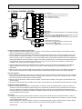
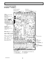
7-2. TEST POINT DIAGRAM
Branch box controller board
PAC-MK50BCPAC-MK30BC
TH-A to E Connect to
Thermistor-A to E
TH-D and E for PAC-MK50BC only
LEV-A to E
Connect to LEV-A to E
LEV-D and E for PAC-MK50BC only
CN3M
Connected to the terminal
block (TB5)
(M-NET transmission connecting wire)
24–30 V DC (non polar)
LED1,LED2
·Start-up
Main power supply
(220/230/240 V AC)
·Normal operating
LED1:Main power supply
LED2:Blink depend on the
total number of indoor
units.
<Example>
The total number is 2,
1Blink 2 times
2Turn OFF for 3 seconds
3Repeat 1–2
SW4
Mode selection
SW12
Address setting 10ths DIGIT
F1
Fuse 6.3 A 250 V
SW11
Address setting 1s DIGIT
SW5
Service setting
SW1
Indoor unit connection
CND
Power supply for
Branch box
Controller board
1–3 220/230/240 V AC
F2,F3,F4
Fuse 10 A 250 V
F4 for PAC-MK50BC
only
TB3A to E
Connect to indoor unit
TB3D and TB3E for PAC-MK50BC only
1–3: Power supply
3–5: Transmission
2–4 220/230/240 V AC 4–6 0–24 V DC
OCH531A
19
OCH531A
OFF
NOT CONNECT
NOT CONNECT
NOT CONNECT
NOT CONNECT
NOT CONNECT
1–3
5–10
4
3
Change INDOOR UNIT No. for
monitoring
—
Automatic restoration when the
power comes back ON.*2
Power-supply voltage setting
Change operation if M-NET
communication error occurs.
INDOOR UNIT-A
INDOOR UNIT-B
INDOOR UNIT-C
INDOOR UNIT-D
INDOOR UNIT-E
NOT USED
2
SW1-1
SW1-2
SW1-3
SW1-4*1
SW1-5*1
SW1-6
Tens digit Ones digit
—
Active
240 V
Continued
operation
Celsius temperature
Refer to "7-4. BRANCH
BOX UNIT OPERATION
MONITOR FUNCTION".
—
Inactive
Stop operation
Fahrenheit
temperature
220 or 230 V
ON
CONNECT
CONNECT
CONNECT
CONNECT
CONNECT
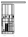
How to set addresses
Example: if address is "3", remain SW12 (for
over 10) at "0", and match SW11 (for 1 to 9)
with "3".
*1 PAC-MK50BC only
*2 Note that the automatic restoration starts after the unit has stopped once.
SW5
Service
setting
SW4
Mode
selection
9 01
SW11
Change temperature indication
1–5
78
1
Rotary switch
SW1
Indoor unit
connection
9 01
SW12
23
45 6
SWU11
Ones digit
address setting
SW12
Tens digit
address setting
23
45 6
78
Remarks
9 01
SW12
9 01
SW11
<Initial settings>
1 2 3 4 5 6
—
1 2 3 4 5 6 7 8 9 10
1 2 3 4 5 6
<Initial settings>
ON
OFF
<Initial settings>
ON
OFF
<Initial settings>
Tens digit Ones digit
Can be activated at ON
any time
OFF
—
Before turning
the power ON
Before turning
the power ON
Set at factory only
Before turning
the power ON
Before turning
the power ON
Operation in Each Switch Setting
OFF
When to Set
78
ON
78
Function
23
45 6
Step
23
45 6
Switch
—
—
—
After each indoor unit is connected to the outdoor unit, turn ON the
switch corresponding to each indoor unit. For example, when the
indoor units are connected to INDOOR UNIT-A and C, turn SW1-1
and SW1-3 to ON.
—
Additional Information
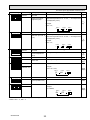
7-3. INTERNAL SWITCH FUNCTION TABLE
The black square (■) indicates a switch position.
20
7-4. BRANCH BOX UNIT OPERATION MONITOR FUNCTION
<Branch box unit operation monitor function>
[When option part ‘A-Control Service Tool (PAC-SK52ST)’ is connected to branch box controller board (CNM)]
Digital indicator LED1 displays 2 digit number or code to inform operation condition and the meaning of check code by
controlling DIP SW2 on ‘A-Control Service Tool’.
<Table1> SW5 setting
SW5 setting
The black square (■) indicates a switch position.
Detail
ON
Common
1 2 3 4 5 6
ON
Indoor-A
Operation indicator:
• SW2 - Use to set the displayed item
• SW5 - Use to set the displayed unit
1 2 3 4 5 6
ON
1 2 3 4 5 6
ON
Indoor-B
1 2 3 4 5 6
ON
Indoor-C
1 2 3 4 5 6
ON
Indoor-D
1 2 3 4 5 6
ON
Indoor-E
1 2 3 4 5 6
The black square (■) indicates a switch position.
<Table2> Functions
SW2 setting
ON
SW5 setting*1
Common
Display detail
Explanation for display
Status of branch box
1 2 3 4 5 6
Unit
During start-up
0.5 s 0.5 s
During error detection
Displays a check code, and M-NET address of the unit
which the check code was detected.
Example:
If the check code 2520 is detected in the address3,
0.5 s 0.5 s 0.5 s 2.0 s
03
25
―
20
During no power supply
F8
Other
Displays the number of units in operation.
0 to 5
Individual unit
Status of branch box
During start-up
0.5 s 0.5 s
During error detection
Displays a check code, and M-NET address of the selected unit.
During no power supply
F8
Other
Displays an operation mode of the selected unit.
0: Stop
C: Cool/ Dry
H: Heat
d: Defrost
*1 Refer to the <Table 1> for the appropriate setting for the function.
OCH531A
21
―
The black square (■) indicates a switch position.
SW2 setting
SW5 setting*
Common
ON
Individual unit
1 2 3 4 5 6
1
Display detail
Not used
Actual opening pulse
of LEV
(Direct-operated
conversion value)
0 to 500
Explanation for display
―
Common
Not used
Individual unit
Error history
1 2 3 4 5 6
―
0 to 500
(When it is 100 pulse or more, it displays a hundredth,
tens, and ones digit by turns.)
Example:
When 150 pulse,
0.5 s 0.5 s 2.0 s
―
―
Displays a check code, and M-NET address of the unit
which the check code was detected.
Example:
If the check code 2520 is detected in the address3,
0.5 s 0.5 s 0.5 s 2.0 s
03
ON
1 2 3 4 5 6
1 2 3 4 5 6
ON
20
25
The number of unit (s) 0 to 5
operating in Thermo-ON
Number
Individual unit
Operating status of unit 83: Abnormal
00: Stop
06: Forced stop
0C: Defrost
29: Hot adjust mode
05: Standby mode
2A: Auxiliary heater is ON.
0A: Thermo-ON
01: In operation Code
display
Individual unit
The number of indoor
0 to 5
unit (s) connected to this
branch box.
00 to FF
M-NET address
Displays an M-NET address of the selected unit.
Common
Not used
Individual unit
Capacity setting in Qj
―
03 to 50
Common
Not used
Individual unit
Indoor thermistor
<pipe temperature/
liquid> (TH2)
1 2 3 4 5 6
―
−39 to 88 [−38 to 190]
(When the temperature is 0: or less, "−" and temperature
are displayed by turns.)
Example:
When −5:,
0.5 s 0.5 s 2.0 s −
*1 Refer to the <Table 1> for the appropriate setting for the function.
*2 SW4-1 OFF = :, ON = -F
OCH531A
22
Number
Code
display
―
Code
display
1 2 3 4 5 6
ON
Code
display
Common
Common
ON
Pulse
50
1
ON
Unit
5
―
:
[-F]*2
The black square (■) indicates a switch position.
SW2 setting
ON
SW5 setting*
Common
Individual unit
1 2 3 4 5 6
1
Display detail
Explanation for display
―
Not used
Indoor thermistor
<pipe temperature/
2-phase> (TH5)
−39 to 88 [−38 to 190]
(When the temperature is 0: or less, "−" and temperature
are displayed by turns.)
Example:
When −5:,
0.5 s 0.5 s 2.0 s
−
ON
Not used
Individual unit
−42 to 91 [−43 to 196]
Branch box pipe
thermistor (TH-A, B, C, (When the temperature is 0: or less, "−" and temperature
D, E)
are displayed by turns.)
―
Example:
When −5:,
0.5 s 0.5 s 2.0 s
−
ON
1 2 3 4 5 6
ON
ON
1 2 3 4 5 6
Not used
Individual unit
Indoor thermistor
<room temperature>
(TH1)
Common
Not used
Individual unit
Set temperature of
indoor unit
16 to 31 [61 to 88]
Common
S/W version
Displays a S/W version number.
―
8 to 39 [43 to 102]
Example:
If it is a ver. 12.34,
0.5 s 0.5 s 2.0 s
12
ON
Common
Not used
Individual unit
LEV opening pulse
(gear operated value)
Common
S/W ROM check sum 0000 to FFFF
1 2 3 4 5 6
ON
1 2 3 4 5 6
―
0b
OCH531A
23
―
―
:
[-F]*2
Code
display
―
Pulse
Example:
If it is 0BC9h, 0.5 s 0.5 s 2.0 s
*1 Refer to the <Table 1> for the appropriate setting for the function.
*2 SW4-1 OFF = :, ON = -F
:
[-F]*2
34
0 to 2000
Individual unit
―
:
[-F]*2
―
Individual unit
:
[-F]*2
5
Common
1 2 3 4 5 6
―
5
Common
1 2 3 4 5 6
Unit
C9
Code
display
8
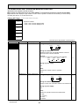
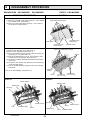
DISASSEMBLY PROCEDURE
BRANCH BOX : PAC-MK50BC
PAC-MK30BC
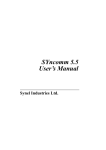
PHOTO : PAC-MK50BC
PHOTOS
OPERATING PROCEDURE
Photo 1
1. Removing the controller cover and under panel
(1) Remove 3 controller cover fixing screws (4 o 10) to detach
the controller cover. (See Photo 1)
(2) Remove 4 under panel fixing screws (4 o 10) to remove
the under panel. (See Photo 1)
Under panel fixing screws
Controller cover
fixing screw
Under panel
Controller cover
Controller cover
fixing screws
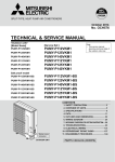
2. Removing the thermistor (TH-A–E*)
Photo 2-1
(1) Remove the controller cover. (See Photo 1)
(2) Remove the under panel. (See Photo 1)
(3) Remove 8 insulations, then remove 9 pipe box (under) fixing screws (4 o 10). (See Photo 2-1)
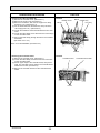
(4) Pull out the thermistor(s), TH-A–E, from the sensor holders mounted on the gas pipe. (See Photo 2-2)
(5) Loosen the insulation sheet which bundles the thermistor
connectors.
(6) Loosen the side clamps, then disconnect the connector(s)
on the controller board.
(7) Pull out the lead wire(s) through the hole to the controller
board side.
Pipe box (under) fixing screws
Screws
Pipe box
(under)
*TH-A–C for PAC-MK30BC. (See Photo 2-3)
Screw
Insulations
Insulations
(15 x 12 x 45)
(15 x 15 x 46)
Photo 2-2
Photo 2-3
Sensor holder
Sensor holder
Header assy
LEV assy
Rubber mount
hole
Insulation sheet
OCH531A
LEV assy
Rubber mount
Band
Band
Header assy
24
hole
Insulation sheet
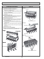
PHOTOS
OPERATING PROCEDURE
3. Removing the LEV coil (LEV-A–E*)
(1) Remove the controller cover. (See Photo 1)
(2) Remove the under cover. (See Photo 1)
(3) Remove 8 insulations, then remove 9 pipe cover fixing
screws (4 x 10). (See Photo 2-1)
(4) Cut the bands that fixes the lead wire, then pull out the
LEV coil(s) (LEV-A–E*). (See Photo 3)
(5) Loosen the insulation sheet which bundles the LEV lead
wires.
(6) Loosen the side clamps, then disconnect the connector(s)
on the controller board.
(7) Pull out the lead wire(s) through the hole to the controller
board side.
(See Photo 2-2 or 2-3)
Photo 3
Bands Header assy
Rubber mount
LEV assy
Bands
*LEV-A–C for PAC-MK30BC. (See Photo 2-3)
LEV coil
4. Removing the controller board
(1) Remove the controller cover. (See Photo 1)
(2) Loosen the side clamps, then disconnect the connectors
on the controller board.
(3) Pick an upper edge of the controller board, then pull forward. The controller board is fixed to the controller board
holder with 4 hooks. (See Photo 4)
(4) Remove the controller board from the controller board
holder.
Photo 4
Controller board
Hooks
OCH531A
25
Controller board holder
PHOTOS
OPERATING PROCEDURE
5. Removing the LEV assy
Photo 5-1
(1)Removethecontrollercover.(SeePhoto1)
LEVassy
(2)Removetheunderpanel.(SeePhoto1)
(3)Remove8theinsulations,thenremove9pipecoverfixing
screws(4x10).(SeePhoto2-1)
(4)Loosenthesideclamps,thendisconnecttheLEVconnectorsonthecontrollerboard.
(5)Pullouttheleadwiresthroughtheholetothecontroller
boardside.
<Removing the header assy>
(6)CutthebandwhichfixestheheaderassyandLEVassy
together,thenremovetherubbermount.(SeePhoto3)
(7)Removetheheaderassy.(SeePhoto5-1)
<Disassembling the pipe box>
(8)Remove2sidepanelfixingscrews(4x10).(SeePhoto5-1)
(9)Pulloutthepipebox(top)andseparateitfromtheside
panel.(SeePhoto5-2)
(10)Turnthepipebox(top)upsidedown.(SeePhoto5-3).
(11)Remove5insulations,thenremove5pipebox(top)fixing
screws(4x10).
Photo 5-2
(12)Turnthepipebox(top)upsidedownagain,facingthepipe
sideup.
(13)Separatethepipebox(center)fromthepipebox(top).(See
Sidepanel
Photo5-4.)
(14)RemovetheLEVassy.
Sidepanelfixingscrews
<Pipe box cap only for PAC-MK30BC>
Thepipeboxcapsareplacedin2unusedpipeholesbetween
thepipeboxtop,centerandunder.(SeePhoto5-5)
Photo 5-4
Pipebox(center)
Pipebox(top)
Photo 5-3
Insulations(15x15x35)
Photo 5-5
Pipeboxcaps
Pipebox
(top)
Pipebox(top)fixingscrews
OCH531A
26
OCH531A
27
HEAD OFFICE : TOKYO BLDG., 2-7-3, MARUNOUCHI, CHIYODA-KU, TOKYO100-8310, JAPAN
cCopyright 2014 MITSUBISHI ELECTRIC CORPORATION
Distributed in Mar.2015 No.OCH574 REVISED EDITION-A
Distributed in Sep.2014 No.OCH574
Made in Japan
New publication, effective Mar. 2015
Specifications are subject to change without notice.