1
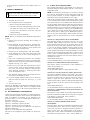
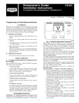
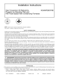
installation and
start-up instructions
TSTAT
BUILDER’S NON-PROGRAMMABLE
THERMOSTAT
Cancels:
II TSTAT-0-25
II TSTAT-0-26
8-99
NOTE: Read the entire instruction manual before starting the
installation.
SAFETY CONSIDERATIONS
Read and follow manufacturer instructions carefully. Follow all
local electrical codes during installation. All wiring must conform
to local and national electrical codes. Improper wiring or installation may damage thermostat.
Recognize safety information. This is the safety-alert symbol
.
When you see this symbol on the equipment and in the instruction
manual, be alert to the potential for personal injury.
Understand the signal words DANGER, WARNING, and CAUTION. These words are used with the safety-alert symbol. DANGER identifies the most serious hazards which will result in severe
personal injury or death. WARNING signifies a hazard which
could result in personal injury or death. CAUTION is used to
identify unsafe practices which would result in minor personal
injury or product and property damage.
INTRODUCTION
The Builder’s Model thermostat is an electronic 24-vac, nonprogrammable, manual changeover wall mount thermostat. This
thermostat uses a single set point to maintain and control room
temperature in both the heating and air conditioning modes. The
thermostat is designed to maintain +/- 2°F accuracy. No batteries
are required; temperature, fan, mode, and installer configuration
settings are preserved with power off.
INSTALLATION CONSIDERATIONS
A.
Air Conditioner Model
TSTATBBBAC01-B, the Builder’s Model air conditioner thermostat, may be wired with or without connecting a common wire
between the indoor equipment and the thermostat. However, it is
recommended to use a common wire whenever possible. Without
a common wire this thermostat becomes "power stealing." This
means it will need to steal a small amount of power from the
equipment to which it is connected. When "power stealing"
method is used, the supplied 270 ohm load resistor must be
connected at the indoor unit. (See Fig. 2, 3, 5, and notes.)
NOTE: Not all HVAC equipment is compatible with power
stealing type thermostats. For all non-Bryant equipment, consult
the system equipment Installation Instructions before applying this
thermostat in a power stealing manner.
—1—
A98191
Fig. 1—Builder’s Non-Programmable Thermostat
CAUTION: The following Bryant equipment is not
compatible with the AC version (TSTATBBBAC01-B)
of this thermostat.
355MAV
Variable Speed Furnace
394HAD, 396HAD
373LAD, 383KAD
Standing Pilot Furnace
361A, 362A, 363A
367A, 369A
Oil Furnaces
349MAV
Gas Furnace
TSTATXXCNV10
Thermostat Conversion Kit
B. Heat Pump Model
TSTATBBBHP01-B, the Builder’s Model heat pump thermostat,
is compatible with all Bryant heat pump systems. It is NOT power
stealing and MUST have both the R and C terminals connected to
operate properly. This thermostat uses a green LED to indicate
auxiliary heat and emergency heat operation.
I. THERMOSTAT LOCATION
Thermostat should be mounted:
• Approximately 5 ft (1.5m) from floor.
• Close to or in a frequently used room, preferably on an inside
partitioning wall.
• On a section of wall without pipes or duct work.
Thermostat should NOT be mounted:
• Close to a window, on an outside wall, or next to a door leading
to the outside.
• Exposed to direct light and heat from a lamp, sun, fireplace, or
other heat-radiating object which may cause a false reading.
• Close to or in direct airflow from supply registers and return-air
grilles.
•
II.
A.
In areas with poor air circulation, such as behind a door or in
an alcove.
To Enter the Configuration Mode:
Press and hold FAN button for approximately 10 sec until room
temperature disappears and the display reads "01". You are now in
configuration mode.
NOTE: If FAN button is pressed again, or if no button is pressed
for 2 minutes, the thermostat will exit configuration mode and
return to normal operation. To re-enter configuration mode, the
FAN button must be pressed and held for 10 sec again.
While in the configuration mode, the temperature display is used
to show both the option number and the selected choice within
each option. Each press of the MODE button alternates between
the option number and the selection within that option. When the
configuration mode is first entered, option 01 is displayed. The up
and down buttons now move between the available option numbers. Once an option number is selected, press the MODE button
once to display the currently selected choice within that option.
After the new choice is made, press the MODE button again to
return to the option number display. When finished with option
selections, press the FAN button once to exit the configuration
mode.
INSTALL THERMOSTAT
WARNING: Before installing thermostat, turn off all
power to unit. There may be more than 1 disconnect.
Electrical shock can cause personal injury or death.
1. Turn OFF all power to unit.
2. If an existing thermostat is being replaced:
a. Remove existing thermostat from wall.
b. Disconnect wires from existing thermostat, one at a time.
Be careful not to allow wires to fall back into wall.
c. As each wire is disconnected, record wire color and
terminal marking.
d. Discard or recycle old thermostat.
NOTE: Mercury is a hazardous waste and MUST be disposed of
properly.
OPTION 01—ANTICIPATOR VALUE ADJUSTMENT
This adjustment controls the sensitivity and cycle rate of the
thermostat. Higher numbers increase the cycle rate in cooling.
Lower numbers increase the cycle rate in heating. However, this
feature will not allow more than 4 equipment cycles per hour (or
1 cycle every 15 minutes), regardless of setting. Values can range
from 1 to 3. Factory default setting is 2. This default selection will
provide optimum performance in nearly all installations. Try this
setting first. Do not change setting unless there is evidence or need
to do so. Unlike conventional anticipators, this setting is not to be
determined by current draw. There is no need to measure, know, or
compensate for current.
AVAILABLE SELECTION:
Use UP and DOWN buttons to move between values 01, 02, or 03.
3. Separate front and back (mounting base) assembly of
thermostat.
4. Route thermostat wires through hole in mounting base.
Level mounting base against wall (for aesthetic value only,
thermostat need not be leveled for proper operation) and
mark wall through 2 mounting holes.
5. Drill two 3/16-in. mounting holes in wall where marked.
6. Secure mounting base to wall with 2 anchors and screws
provided making sure all wires extend through hole in
plastic.
7. Strip 1/4 in. insulation from thermostat wire and adjust
length to reach terminal block connector on mounting base.
Match and connect proper wiring in accordance with wiring
diagrams. (See Fig. 2, 3, 4, and 5.)
OPTION 03—FAHRENHEIT/CELSIUS SELECTION
This selection operates the thermostat in either Fahrenheit or
Celsius. Factory default is F.
AVAILABLE SELECTION:
Use UP and DOWN buttons to change between F and C.
8. Push any excess wire back into wall. Seal hole in wall to
prevent air leaks. Leaks can affect thermostat operation.
Any excess wire left inside thermostat casing may also
affect thermostat operation by interfering with airflow
across the temperature sensor.
OPTION 04—G (FAN) ON WITH W (HEAT) SELECTION
This selection determines whether G (fan) output is to be ON or
OFF when W (furnace or strip heat) output is ON. Most furnaces
and fan coils manage their own blowers and do not require a
separate G signal. For these applications, select OFF. Some
auxiliary heaters require a separate G signal from the thermostat to
turn on the blower. In this case, select ON. Factory default is OF
(off).
AVAILABLE SELECTION:
Use UP and DOWN buttons to change between ON and OFF.
9. Snap thermostat together making sure terminal block connector aligns, and assembly is secure.
10. If "power stealing" method is used, be sure to attach 270
ohm load resistor at indoor unit. (See Fig. 2, 3, 5, and
notes.)
11. Turn on power to unit.
On power up, depending on the thermostat model being used, the
LCD readout will display either, HC for air conditioner model
(1-stage heat/1-stage cool), or HP for heat pump model (2-stage
heat/1-stage cool).
OPTION 10—O (REVERSING VALUE) ON WITH HEAT OR
COOL SELECTION
This selection is only available on heat pump model thermostats.
This selection determines whether the reversing valve is energized
in the heating or cooling mode. Factory default is C.
AVAILABLE SELECTION:
Use UP and DOWN buttons to change between H and C.
III. SET THERMOSTAT CONFIGURATION
Configuration options allow the installer to configure the thermostat for a particular installation. These selections are intended to be
made at installation and normally are not modified by the
homeowner. Below is a list of available options followed by a
description of each one.
Option 01 -- Anticipator adjustment
Option 03 -- Fahrenheit or Celsius operation
Option 04 -- Enable fan (G) ON with heat (W)
Option 10 -- O (reversing valve) On with Heat or Cool (present on
Heat Pump model only)
Option 13 -- Room temperature offset adjustment
Note that not all configuration option numbers are used in this
product.
OPTION 13—ROOM TEMPERATURE OFFSET
ADJUSTMENT
This option allows calibration (or deliberate miscalibration) of the
room temperature sensor. There are various reasons why homeowners may want to have displayed temperature adjusted to a
higher or lower value. The selected number is the number of
degrees, plus or minus, which will be added to actual temperature.
The numbers can range between -5 and +5. Factory default is 1.
—2—
AVAILABLE SELECTION:
Use UP and DOWN buttons to move between -5 and +5 in steps
of 1.
IV.
THERMOSTAT OPERATION
A.
Temperature Display
However, if the heating demand is greater than 5°, there will be
only a 3-minute delay before bringing on W.
F.
″--″ (two dashes) will be displayed if the thermostat can not
properly read room temperature. If ″--″ appears, replace thermostat.
Thermostat will display room temperature until UP or DOWN
button is pressed. The word SET appears when these buttons are
pressed and the current set point is displayed. If no buttons are
pressed for 5 sec, the display will change back to show room
temperature.
B.
Error Messages
E4 will be displayed if the thermostat has an internal memory
failure. If E4 appears, replace thermostat.
V.
CHECK THERMOSTAT OPERATION
A.
Fan Operation
Timeguard Timer
A 5-minute timeguard is built into the thermostat immediately
upon power up, and any time the compressor turns off. The
compressor will not turn on until the timeguard has expired. The
timeguard affects only compressor operation. Pressing UP and
FAN buttons simultaneously will override the timeguard for 1
cycle.
1. Press FAN button. This will start continuous fan operation.
FAN annunciator will turn on.
2. Press FAN button again. This will stop continuous fan
operation. FAN annunciator will turn off.
C. Cycle Timer
In normal heating and cooling operation the thermostat will not
allow more than 4 equipment cycles per hour (or 1 cycle every 15
minutes). Both the Y and W outputs have a 15-minute timer that
starts counting down when the output is turned on, (e.g., if Y
output is turned on for 9 minutes and then satisfies, it cannot turn
back on for another 6 minutes regardless of demand). However,
pressing UP and FAN buttons simultaneously or changing the set
point will override the timer for 1 cycle.
B.
Heating Operation
1. Press MODE button until HEAT is displayed.
2. Press UP button until LCD readout reads 30° above room
temperature. Press UP and FAN buttons simultaneously to
defeat timers. Heating system should begin to operate
immediately.
3. For HP thermostats only, press MODE button until EMHT
(emergency heat) appears. Press UP and FAN buttons
simultaneously to defeat timers. Emergency heating (W is
ON, Y is OFF) should begin immediately.
D. Minimum On Timer
Once the equipment has turned on, it will remain on for a
minimum of 3 minutes regardless of demand. However, the
equipment can turn off in less than 3 minutes if a change in set
point or a change in mode occurs.
C.
Cooling Operation
1. Press MODE button until COOL is displayed.
E. Staging Timer
If the thermostat is a heat pump model, it has 2-stage heat
capability. In normal operation there is a 15-minute delay between
the first and second stages of heat. The Y output will energize first,
then 15 minutes later, W is allowed to come on if the thermostat
determines it is not satisfying the demand.
2. Press DOWN button until LCD readout reads 30° below
room temperature. Press UP and FAN buttons simultaneously to defeat timers. Cooling system should begin to
operate immediately.
BUILDER’S MODEL THERMOSTAT CONFIGURATION RECORD
Owner/Operator __________________________________________ Date ________________________________________________
Indoor Unit Model No. ______________________________________ Outdoor Unit Model No. _________________________________
A) Mode Settings
_____ Mode (OFF, HEAT, COOL, EMHT)
_____ Heat/Cool Set Point Value
_____ Fan (AUTO or ON)
B) Configuration Options
1
3
4
10
13
_____ Anticipator (1-3: factory default = 2)
_____ Fahrenheit or Celsius (F or C: factory default = F)
_____ Fan On with W (Off or On: factory default = Off)
_____ O (reversing valve) On with heat (H), or Cool (C) (factory default = C)
_____ Room Temperature Offset (-5 to +5: factory default = 0)
(Note: Configuration Options 2, 5, 6, 7, 8, 9, 11, 12 are not applicable)
A99277
—3—
AC
THERMOSTAT
HEATING
W
W
FAN
G
G
24 VAC HOT
R
R
24 VAC COMM
C
COOLING
Y
N/A
O
*
270 Ω, 10 W *
RESISTOR
(SUPPLIED)
C
C
Y
Y
TYPICAL
FAN COIL/
FURNACE
AC
THERMOSTAT
TYPICAL
FAN COIL/ SINGLE-SPEED
FURNACE AIR CONDITIONER
HEATING
W
W
FAN
G
G
24 VAC HOT
R
R
24 VAC COMM
C
COOLING
Y
N/A
O
*
270 Ω, 10 W *
RESISTOR
(SUPPLIED)
C
Y
* See note 1
A99115
* See note 1
A99154
Fig. 3—Typical Heat Only
Fig. 2—Typical Air Conditioner
HEAT PUMP
THERMOSTAT
TWO-ZONE
THERMOSTAT
INPUT
AC
THERMOSTAT
TYPICAL SINGLE-SPEED
HEAT PUMP
FAN COIL
HEAT STAGE 2
W
W
W
HEATING
W
W1
REVERSING
VALVE
O
O
O
FAN
G
G
FAN
G
G
24 VAC HOT
R
R
24 VAC HOT
R
R
R
24 VAC COMM
C
24 VAC COMM
C
C
C
COOLING
Y
HEAT/COOL
STAGE 1
Y
Y
Y
N/A
O
*
C
Y1
270 Ω, 10 W *
RESISTOR
(SUPPLIED)
* See note 2
A98217
A99116
Fig. 5—Two-Zone with Air Conditioner
Fig. 4—Typical Heat Pump
*WIRING DIAGRAM NOTES
1. If "power stealing" method is used, leave C terminal disconnected between thermostat and equipment and add the supplied 270 ohm load
resistor as shown.
2. Power stealing method may not be used with the Two-Zone system. In addition, the supplied 270 ohm load resistor MUST always be
connected between Y1 and C at Two-Zone input as shown.
© 1999 Bryant Heating & Cooling Systems 7310 W. Morris St. Indianapolis, IN 46231
—4—
Printed in U.S.A.
iitst026
Catalog No. 13TS-TA16