1
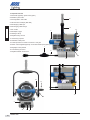
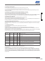
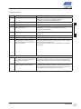
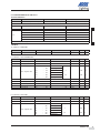
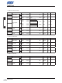
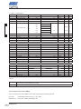
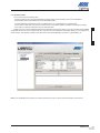
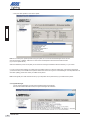
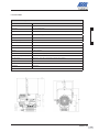
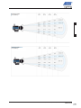
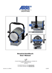
User Manual
L7
Arnold & Richter Cine Technik GmbH & Co. Betriebs KG
D-83071 Stephanskirchen
Germany
Kontaktinformationen unter www.arri.com
For contact information visit www.arri.com
Ident.No. L5.31899.0
ENGLISCH
Table of Contents
1.
General
1.1
Important Notes and Safety Instructions
36
1.1.1
General Notes
36
1.1.2
Important Safety Instructions
36
1.2
Description and Features of your Lamphead
37
1.2.1
Properties
37
1.2.2
Product features
37
2.
General Lamphead Overview
38
3.
Setting up and Securing the Fixture
39
4.
Basic Functions
40
5.
Setting Options
40
5.1
Possible Settings via On-board Control
41
5.1.1
Overview of on-board control
41
5.1.2
Menu levels of the on-board control
42
5.1.3
Setting the operating modes
43
5.1.4
Setting the color temperature (CCT mode)
43
5.1.5
Setting the color (HSI mode)
43
5.1.6
Setting intensity
43
5.1.7
Setting the fan function
43
5.1.8
Setting the DMX address
43
5.1.9
Selecting the DMX profile
44
5.1.10
Turning lights on/off and status request of on-board control
44
5.1.11
Status request
44
a) Operating hours
44
b) DMX version
44
c) Software version
44
d) Operating temperature
44
e) Availability
44
Error messages
45
5.1.12
36
Arnold & Richter Cine Technik GmbH & Co. Betriebs KG, Pulvermühle, 83071 Stephanskirchen
34
www.arri.com
5.2
Possible Settings via DMX
46
5.2.1
DMX profiles
46
5.2.2
DMX In / Pin allocation
46
5.2.3
DMX Implementation table
5.2.4
Conversion CCT value to DMX %
5.2.5
RDM functions
5.3
Possible settings via PC – LSeries Manager
56
5.3.1
LSeries Manager 1.0.2
56
5.3.2
Installing and starting the LSeries Manager
56
5.3.3
Overview
57
5.3.4
DMX Settings with the LSeries Manager
57
5.3.5
Fan control
58
5.3.6
Diagnosis
58
5.3.7
Firmware update
59
5.3.8
System messages
60
6
Technical Data
7
Warranty regulations, Limitations of Liability, EC Declaration of Conformity, Service
47 - 52
53 - 55
ENGLISCH
52
61 - 63
64
Arnold & Richter Cine Technik GmbH & Co. Betriebs KG, Pulvermühle, 83071 Stephanskirchen
www.arri.com
35
1. General
1.1 Important Notes and Safety Instructions
ENGLISCH
1.1.1 General Notes
ARRI L Series fixtures are intended for professional use in the studio and on location and may only be
operated by qualified persons.
Read these instructions carefully before using the device for the first time. The following text contains
important information for safe handling.
Observe the safety instructions and warnings for your own personal safety.
All components comply with the following European standards and directives:
Low voltage directive
EMC directive
RoHS directive
Keep these instructions for possible subsequent owners.
Help protecting our environment by disposing the packing material at your local recycling center.
Use only original ARRI spare parts and accessories (more information at www.arri.com).
1.1.2.
Important Safety Instuctions
DANGER OF LIFE - MAINS VOLTAGE!
Disconnect the device from the mains voltage
before replacing a damaged fuse!
Never bridge a fuse!
CAUTION ! Risk of burns !
The housing and the cooling fins can reach high temperatures.
Keep a safety distance of 10" (0,25 m) to adjacent surfaces on all sides.
Keep the cables away from the fixtures.
Do not cover ventilations slots and cooling fins.
CAUTION ! High Beam Intensity !
Do not look into the light emission aperture of the fixture.
Safety devices may only be removed for service purposes by qualified personnel !
Do not lift or suspend the fixture at the mains cable !
Note the technical data on page 29,30 and 31.
Do not use the fixture or accessories if they display any visible damage on any component.
In case of damage the respective parts must be exchanged or you have to contact an
ARRI Service station (see www.arri.com).
L7 fixtures must not be connected to dimmer systems or dimmer channels in Non-Dim mode.
Doing so will damage the electronic system of the fixture.
Check the fixture for the following possible damage before every use:
part
possible damage
housing, lens
fissures, cracks, deformed
cables
deformed, cut, scorched
plug
deformed, broken, scorched
plug connections
damaged
inner thread
overwound
Also read and follow the additional safety leaflet "Operating your ARRI Lampheads safely" L5.70731.E
Arnold & Richter Cine Technik GmbH & Co. Betriebs KG, Pulvermühle, 83071 Stephanskirchen
36
www.arri.com
1.2 Description and features of your Lamphead
The L7 range lampheads are equipped with an electronically controlled LED light source. You can use them like a conventional
tungsten Fresnel fixture but with far higher energy efficiency. The newly developed optical system offers a continuous
focus range of 15-50° half peak angle and real 'Fresnel' characteristics: an extremely uniform light field and clean shadow
rendition. While the L7-T generates light with a color temperature of 3,200K, the L7-C has a tunable light source to generate 2,800K
to 10,000K color temperature and even saturated colored light. The light spectrum has been specifically designed for excellent
color rendition. All fixtures can be controlled over USB interface, DMX 512 / RDM protocol or on-board control panel (if equipped).
1.2.1 Properties
Versatile beam characteristics
The L7 provides the same ability as conventional Fresnel lenses to cut set elements and shape the light field
with barndoors and flags.
ENGLISCH
Focus
Versatility is the key element in traditional Fresnels, especially the ability to spot and flood the beam as needed. Whether it’s
a flood field for a pullback shot or a tight spot for a bright highlight, the continuous focusability of the L7 performs
just as expected.
Even light field
Clear, defined shadows have traditionally been a trait only of single source tungsten and daylight fixtures. ARRI L7 Fresnels
provide the same single shadow properties designers expect, delivering natural results.
Vibrant colors, full-spectrum lighting
True-to-life color rendition is an outstanding feature of the L range, comparable to a full-spectrum tungsten source. The fully
tuneable White light of the L7 C can be adjusted for different skin tones, camera sensors and mixed-light environments. Full
gamut color mixing enables the rendition of all color shades, making color filters dispensible.
Cool light beam
Like all LED light sources the L7 does not emitt infrared or UV radiation and thus no forward heat, making talent feel
comfortable in the light beam.
The ARRI L range combines all advantages of LED technology and the traditional Fresnel lens. It integrates seamlessly into established working practices, so that designers can stick with their creative techniques and studios will have no need to change their
operating procedures.
1.2.2 Product features
Focus knob
True Blue-style focus knobs provide precise adjustment and rapid flood-to-spot with only three turns. Knobs on both sides of
the fixture ensure easy access from all positions.
Sliding stirrup
The sliding stirrup design enables precise compensation for front-end accessories.
Yoke
With an extremely slim profile, the extruded aluminum yoke provides high strength without added weight. An optional poleoperated yoke allows full operation of pan and tilt from the floor and is therefore a popular choice for many studios.
Tilt lock
The high strength tilt lock provides extremely secure locking, eliminating movement and slippage and ensuring that the fixtures
will stay where you put them.
DMX control
All functions of the L7 are controllable through DMX. The L7 is also fully RDM compatible and is equipped with a feedback
channel for reporting all set parameters including system status and hours on the light engine.
On-board control
For location applications the L7 is equipped with an on-board control for manual adjustment of intensity, color temperature and
plus/minus Green as well as hue and saturation.
Arnold & Richter Cine Technik GmbH & Co. Betriebs KG, Pulvermühle, 83071 Stephanskirchen
www.arri.com
37
2. Lamphead overview
1 Netzschalter (optional) / power switch (option)
2 Netzkabel / power cable
8
3 Sicherungshalter / fuse holder
4 USB-Anschluss / USB port (Mini USB)
5 DMX-Eingang / DMX input
ENGLISCH
6 DMX-Ausgang / DMX through
9
7 Griff / handle
11
7
8 Stativzapfen / spigot
9 Haltebügel / stirrup
16
10 Bügelklemmung / tilt lock
11 Torsicherung / top latch
12 Rasthaken / safety catch
13 Fokusknopf oder P.O.-Antrieb / focus knob or P.O. gear
12
14 Bedien- und Anzeigefeld (optional) / control and indicator panel (option)
1
15 Bügellager / stirrup bracket
16 Linsenfassung / lens door
2
17 Bügelklemmhebel / tilt lock lever
13
14
15
17
P.O. - Version
13
10
4
3
5
6
Arnold & Richter Cine Technik GmbH & Co. Betriebs KG, Pulvermühle, 83071 Stephanskirchen
38
www.arri.com
3. Setting up and securing the fixture
Tools needed
Torx screwdriver no. 20
Torque wrench / Allen key no. 10 (50 Nm)
ENGLISCH
Adjusting the stirrup
On delivery the stirrup (9) is in the basic position, which means it is tilted to the back.
Use the Torx screwdriver no. 20 to slightly loosen the screws on both sides of the stirrup bracket (15) and pull the stirrup
bracket towards the rear of the lamphead. The lever of the tilt lock (10) has to be loosened, so that you can tilt the stirrup (9)
upwards.
In order to position the stirrup at the ideal balance point move it to a position halfway in-between the front and rear of the
lamphead housing. Then tighten the screws at the stirrup bracket (15) again. Now tilt the stirrup to the desired angle and
tighten the tilt lock lever. For better leverage, press the knob on the tilt lock lever (17) and turn the lever to the desired
position.
Mounting the spigot
Place the spigot (8) and the spacer onto the boring in the stirrup (9), insert the screw with washer and spring washer from
below and fasten it with the torque wrench to 50 Nm = 37 lbf ft (pound force feet).
Installation of the PC software
Download the latest LSeries Manager version from the internet (download center: http://www.arri.com/l-series/downloads).
Be aware that the installation can only be performed, if you have administrative rights. If your user profile does not grant
administrative rights you have to let the installation file (.exe) run as follows:
Right-click on the file „start as administrator“.
Start the program by double-clicking on the generated shortcut.
After the installation is completed you can connect your lamphead via USB cable to your computer. The LSeries Manager
automatically detects the connected lampheads. Make sure that no other DMX program is communicating with the lamphead.
You can operate one lamphead with any one USB port.
Tip: After the installation is complete, we recommend connecting the lamphead before you start the LSeries Manager for the
first time. Doing this will complete the driver installation and prevent a possible connection time-out.
Note: Wait with connecting your lamphead to the computer until the installation of the LSeries Manager is complete. The LSeries
Manager allows you to operate several L7 lampheads and also update them simultaneously.
Securing the lamphead and the accessories
When mounting the fixture in a hanging position, additionally secure the fixture with a safety cable from the mounting pipe or
truss through the fixture stirrup. The safety cable must be properly dimensioned for the fixture and application and must be
kept short.
The carrying capacity of the safety rope must be rated at a minimum of 10 times the weight of the lamphead system including
accessories.
Be aware of the maximum allowed tilt angle of 90° up and 90° down.
When the lamphead is operated in a hanging position, ensure that the accessories are installed correctly: top latch (11) locked,
optional barndoor safety catch (12) snapped in.
Stands must be set up in a stable position and capable of carrying the load of the lamphead including accessories and cables!
Also refer to our safety leaflet "Operating Your ARRI Lampheads Safely"; L5.40731.E.
CAUTION! Lateral load can cause deformation or breaking of the spigot (8) or the stirrup (9)!
Arnold & Richter Cine Technik GmbH & Co. Betriebs KG, Pulvermühle, 83071 Stephanskirchen
www.arri.com
39
4. Basic functions
Securing the fixture
The lamphead must be fastened at its stirrup (9) in a standing or hanging position. The spigot (8) must be inserted into the
husk of a matching stand or a matching holding device and must be clampt in and secured there.
ENGLISCH
Rotation and tilt
The lamphead can be rotated after the screw at the stand or holding device has been loosened. In order to change the tilt,
loosen the tilt lock (10). After rotating or tilting the lamphead, the screws or lock levers must be tightened again.
Adjusting the beam angle
The beam angle can be continuously adjusted by turning the focus knob (13). When you do this the entire lens unit is moved out
of or into the lamphead housing.
This mechanism protects the fixture in two ways:
· A predetermined breaking point prevents damage at the lamphead if the focus knob is turned with too much torque.
· A self-impeding gear prevents that the position of the lens unit changes while the lamphead is operated in a tilted position.
Using accessories for light design
Accessories for light design, such as a barndoor or filter holders, can be inserted into the holding brackets on the front of the
lamphead. To do this proceed as follows:
· Firmly press the button at the side of the top latch; the top latch flips upwards.
· Insert the accessory from the upside into the holding brackets, until the safety catch (12) engages. Slightly tilt the safety catch
with your finger for support.
· Close the top latch (11) and make sure that the hook of the top latch engages in the holding ring of the accessory.
DMX interface
The lamphead is equipped with an RDM/DMX interface with a waterproof input socket. The not waterproof DMX distributor box
which is mounted at this socket has one DMX in and out and has the purpose of looping the DMX line throuhg to the next
lamphead. It can be removed after loosening the fixing screw.
USB interface
The lamphead is also equipped with a USB interface with a mini USB slot, which can be used for updating the fixture's
internal firmware, for adjusting operating parameters and for service purposes. The service tool "LSeries Manager" allows you to
configure your lamphead via this interface, you can download the LSeries Manager from the ARRI homepage free of charge.
(Download center: http://www.arri.com/l-series/downloads)
Turning on and operation
After you have turned on the power switch (or after connecting to mains power for lampheads without a power switch) the
lamphead will need a short start-up time before it lights up. The lamphead will operate with the previously used setting. It can
now be controlled via the DMX interface or the on-board control.
CAUTION! Hight beam intensity ! Do not look into the ligth emission aperture of the lamphead.
5. Setting Options
You have four options to configure or control your lamphead:
Type
control
configuration
on-board control
yes
yes
USB - LS Manager
no
yes
DMX - mixing console or computer
yes
no
RDM - USB on RDM Box with PC software
yes
yes
Arnold & Richter Cine Technik GmbH & Co. Betriebs KG, Pulvermühle, 83071 Stephanskirchen
40
www.arri.com
5.1 Possible settings via on-board control
5.1.1 Overview of on-board control
17
18
26
19
16
20
ENGLISCH
15
B
C
21
24
22
25
23
Depending on the model, your lamphead is equipped with one of the following display or control panels:
· simple display field (A)
· on-board control with LC display and intensity control (B)
· on-board control with LC display, intensity and color control (C)
A
no.
name
15
POWER-/STATUS-LED display
short description
16
DATA display
signalises a present DMX signal
17
FUNCT - button
1. function: changes between CCT & HSI mode
2. function: jump one menu level UP
18
ENTER - button
1. function: jump one menu level DOWN
2. function: confirm settings
3. function: „flash“ arrow for activating quick selection
(memory button 1 = 3200K, memory button 2 = 5600K)
19
+ / UP / step up value
navigate within a menu level or step up values
(keep button pressed for stepping up rapidly)
20
- / DOWN / step down value
navigate within a menu level or step down values
(keep button pressed for stepping down)
21
rotary knob INTENSITY
set intensity
22
rotary knob CCT / HUE
set color temperature or hue
23
rotary knob GN / SAT
set green-magenta correction or saturation
24
memory button 1
safe or retrieve settings
25
memory button 2
safe or retrieve settings
26
display
Status LEDs at on-board control:
green LED lights up
status OK / lamphead active
blue LED lights up
receiving DMX or RDM data
red LED flashes at 500ms rhythm *
lamphead will shortly reach over temperature
red LED lights up permanently *
over temperature reached
red LED goes out and Green LED lights up *
lamphead has cooled down and can be turned on again
red LED flashes rapidly at 250ms rhythm *
calibration data could not be loaded
* display lights up red when LED is lit
Arnold & Richter Cine Technik GmbH & Co. Betriebs KG, Pulvermühle, 83071 Stephanskirchen
www.arri.com
41
5.1.2 Menu levels of the on-board control
During the operation of the lamphead the selected operating mode with the current value is displayed. On the first menu level the
values for INTENSITY, CCT/HUE and GN/SAT can be retrieved via the + / - buttons. The menu point STATUS, confirmed with
ENTER, takes you to the next level which displays information on faultless operation and the temperature. To retrieve values for
operating hours, DMX version and software version, press ENTER to jump to the third level. The FUNCT key takes you back to the
previous menu level.
ENGLISCH
Note: The horizontal arrow in the display symbolizes the possibility to jump to the next menu level by pressing ENTER.
menu level 1
display
Intensity
e.g. 24 %
CCT/HUE
e.g. 2900K / 16°
GRN/SAT
e.g. -0,57 / 100
menu level 2
OK or ERROR
display
menu level 4
e.g. 501 t
e.g. 3.1
e.g. 1.70.0
e.g. 42.1° (temperature)
HOUR (operating hours)
DMX V (DMX version)
STATUS
SETUP
menu level 3
PROT (protocol number)
e.g. P.001
CHAN
e.g. C.017
SW (software version)
DMX (DMX settings)
ON or OFF
INDC (lights on control)
FAN (fan modes)
OFF
LOW
HI
ALOW (from 80%)
AHI (from 80%)
VARI (at avg. 158° F)
PASS
HI 45 (only L7 Active)
Note: In setup or status mode the settings option remains active until another function is executed. In all other modes the
display will go back to the respective mode after 2 seconds.
Arnold & Richter Cine Technik GmbH & Co. Betriebs KG, Pulvermühle, 83071 Stephanskirchen
42
www.arri.com
5.1.3 Setting the operating modes
Press the FUNCT key (17) briefly to switch from CCT mode to HSI mode or vice versa.
In CCT mode the lamphead generates White light with optimized color rendition CRI > 95.
In HSI mode the lamphead generates colored light. If saturation is set very low, the lamphead will generate White light, but with
optimized color rendition.
5.1.5 Setting the color in HSI mode
With the rotary knob CCT/HUE (22 ) you can adjust the value for hue continuously.
Use the rotary knob GN/SAT (23) for continuous adjustment of saturation.
You can retrieve the currently set value for saturation by pressing the keys + (19) or - (20) repeatedly until SAT is displayed on the
left side of the display (e.g. 45). The setting for hue is always displayed (e.g. 4118°).
ENGLISCH
5.1.4 Setting the color temperature and Green-magenta adjustment in CCT mode
With the rotary knob CCT/HUE (22) the color temperature can be adjusted continuously.
The rotary knob GN/SAT (23) serves for continuous green-magenta adjustment.
You can retrieve the currently set value for Green-magenta adjustment by pressing the keys + (19) or - (20) repeatedly until GRN is
displayed on the left side of the display (e.g. +0.23). The setting for color temperature is always displayed (e.g. 4150K).
5.1.6 Setting intensity in both operating modes
With the rotary knob INTENSITY (21) you can continuously adjust intensity in both operating modes. You can retrieve the currently
set value for intensity by pressing the keys + (19) or - (20) repeatedly until INTENSITY is displayed on the left side of the display
(e.g. 24%).
5.1.7 Setting the fan functions
You can set the different fan functions via the on-board control from menu level 3.
Proceed as follows:
Press the keys + (19) or - (20) repeatedly until SETUP is displayed in the left lower corner of the display (27).
Confirm with the ENTER key (18). Press the key + (19) or - (20) repeatedly until FAN is shown in the display (27). Confirm with
ENTER (18) again. The currently used fan mode is displayed.
By pressing the keys + (19) or - (20) you can select the desired fan mode (see table below). Confirm your selection with the ENTER
key (18). The fan will now work in the desired mode. Press the FUNCT key (17) twice to leave this menu level.
Fan mode
OFF
L7 Hybrid
L7 Active
x
LOW
x
HI
x
L7-T4
Description of mode
Fan is turned off, it may occur that the lamphead turnes itself off due to
overheating. Once the lamphead has cooled down it can be turned on and
used again.
x
Fan operates constantly at low speed (silent)
Fan operates constantly at maximum speed
A-LOW
x
Fan operates from 80% intensity with 1050 rev/min
A-HI
x
Fan operates from 80% intensity with maximum speed
VARI
x
PASS
x
HI 45
x
Fan is controlled via the light-engine temperature, fan starts at approx.
70°C / 158° F, steps speed up or down automatically
x
Optimized for an ambient temperature of 45°C / 113° F, fan operates at
max. speed, light output is reduced by approx 15%
No fan, light output is reduced by 20%
5.1.8 Setting the DMX address
Go to menu level 4 to set the DMX start address via the on-board control.
Proceed as follows:
Press the keys + (19) or - (20) repeatedly until SETUP is displayed in the left lower corner of the display (27).
Confirm with the ENTER key (18). Press the key + (19) or - (20) repeatedly until DMX is shown in the display (27). Confirm with
ENTER (18) again. Press the key + (19) or - (20) repeatedly until CHAN is shown in the display (27). When you press the ENTER
key now the currently used DMX start address is displayed. Use the keys + (19) or - (20) to select a value from C.001 to C.506 an
confirm your selection with the ENTER key (18). The DMX start address is now set. Press the FUNCT key (17) three times to leave
this menu level.
Arnold & Richter Cine Technik GmbH & Co. Betriebs KG, Pulvermühle, 83071 Stephanskirchen
www.arri.com
43
ENGLISCH
5.1.9 Selecting the DMX profile
In order to select one of the 15 available DMX profiles via the on-board control you have to navigate to menu level 4. To get there,
proceed as follows:
Press the keys + (19) or - (20) repeatedly until SETUP is displayed in the left lower corner of the display (27).
Confirm with the ENTER key (18). Press the key + (19) or - (20) repeatedly until DMX is shown in the display (27). Confirm with
ENTER (18) again. Press the key + (19) or - (20) repeatedly until PROT is shown in the display (27). When you press the ENTER
key the currently used DMX profile is displayed. Use the keys + (19) or - (20) to select a value from P.001 to P.015 and confirm your
selection with the ENTER key (18). The DMX profile is now selected.
Press the FUNCT key (17) three times to leave this menu level.
5.1.10 Turning lights of on-board control on/off
In order to turn the lights at the on-board control on or off you have to navigate to menu level 3. To get there, proceed as follows:
Press the keys + (19) or - (20) repeatedly until SETUP is displayed in the left lower corner of the display (27).
Confirm with the ENTER key (18). Press the key + (19) or - (20) repeatedly until INDC is shown in the display (27). When you
press the ENTER key, the current settings are displayed. Use the + (19) or - (20) keys to select either ON or OFF and confirm with
ENTER (18). The light on the display (26) and LED signals (15 and 16) are now turned on or off. Press the FUNCT key (17) twice
to leave this menu level.
5.1.11 Status request
In order to request the status via the on-board control proceed as follows:
a ) Read operating hours
Press the keys + (19) or - (20) repeatedly until SETUP is displayed in the left lower corner of the display (27).
Confirm with the ENTER key (18). Press the key + (19) or - (20) repeatedly until HOUR is shown in the display (27). When you
press the ENTER key the operating hours are displayed (e.g. 501 t). Press the FUNCT key (17) three times to leave this menu
level.
b ) Read DMX version
Press the keys + (19) or - (20) repeatedly until SETUP is displayed in the left lower corner of the display (27).
Confirm with the ENTER key (18). Press the key + (19) or - (20) repeatedly until DMXV is shown in the display (27). When you
press the ENTER key the version is displayed (e.g. 3.1). Press the FUNCT key (17) three times to leave this menu level.
c ) Read software version
Press the keys + (19) or - (20) repeatedly until SETUP is displayed in the left lower corner of the display (27).
Confirm with the ENTER key (18). Press the key + (19) or - (20) repeatedly until SW is shown in the display (27). When you press
the ENTER key the version is displayed (e.g. 1.70.0). Press the FUNCT key (17) three times to leave this menu level.
d ) Read operating temperature
Press the keys + (19) or - (20) repeatedly until SETUP is displayed in the left lower corner of the display (27).
Confirm with the ENTER key (18). Press the key + (19) or - (20) repeatedly until the temperature (e.g. 42.1°) is shown in the display
(27) . Press the FUNCT key (17) twice to leave this menu level.
e ) Read availability
Press the keys + (19) or - (20) repeatedly until SETUP is displayed in the left lower corner of the display (27).
Confirm with the ENTER key (18). In the display (27) you can see OK or an error code (e.g. E.004 / see table with error messages
on next page). Press the FUNCT key (17) twice to leave this menu level
Arnold & Richter Cine Technik GmbH & Co. Betriebs KG, Pulvermühle, 83071 Stephanskirchen
44
www.arri.com
5.1.12 Error messages
Error
Solution
E.003
Controller over temperature
Let the lamphead cool down. After that the status LED should light up
Green again. The lamphead is available for operation.
Set the fader to 0 and then set the desired value.
E.004
Light Engine over temperature
See solution for E.003
E.005
Power supply over temperature
See solution for E.003
E.006
Calibration data faulty or read error of
light engine memory
NOTICE: Loss of calibration data can only be solved
in the factory. (You might have to exchange the light engine
and carry out calibration again.)
E.007
Invalid PWM value calculation
This merely serves as a notification that a fault has occurred during
calculation.
E.008
Invalid values during calculating step 1
See solution for E.007
E.009
Invalid values during calculating step 2
See solution for E.007
E.010
Fan error. Exeeding deviation from
pre-set speed or fan outage. This error
can only be detected in fans with speed
indicator (3 wire fan).
CAUTION: Only a trained service person is allowed to fix this error!
Set the fan to LOW or HI and see if it starts rotating, in order to determine if there is an electrical malfunction.
All mechanical tests or repairs may only be carried out by a trained service technician.
ENGLISCH
Code
From SW version 1.72.0
E.011
On-board control could not be detected,
or on-board control ID has not been programmed at the lamphead.
If the on-board control is working, error E.011 can be ignored. However,
if the on-board control remains dark (no LED lights up) we recommend
contacting a service partner. They can then carry out detailled analyses.
E.012
Temperature sensor(s) are defective or
deviation within NTC values too high.
One or more temperature sensores are defective or the deviation within
the individual NTCs or BNTCs exceeds the variation tolerance of 54° F.
Check the error log (LSeries Manager) to see which temperature sensores are affected. Ask your service partner to fix this error.
Arnold & Richter Cine Technik GmbH & Co. Betriebs KG, Pulvermühle, 83071 Stephanskirchen
www.arri.com
45
ENGLISCH
5.2 Settings options via DMX
5.2.1 DMX profile
The ARRI L7 range offers 15 DMX profiles, which can be pre-configured by the user. The 8-bit modes should be used with basic
DMX control consoles (dimming consoles). The most common modes for operation are mode 01 and mode 02. ARRI recommends
the use of the 16-bit mode in combination with a DMX control console, which supports functions up to 16-bit resolution in order
to obtain premium results. The increased resolution over the 8-bit mode provides even smoother dimming and continuous color
adjustment. Additionally there is a „Coarse/fine“ mode which allows you to perform a coarse and fine adjustment with two indiviual
DMX channels. The Coarse / Fine modes utilize two DMX channels for most parameters and provide increased resolution over the
8-bit modes for users without 16-bit compatible control consoles.
White and RGBW:
This is the most common mode of operation. It provides control over intensity, color temperature, +/- Green, and individual Red,
Green, Blue, and White color channels.
White:
Simplified White-only mode for use when the number of available channels on a DMX control board is limited. It provides control
over intensity, color temperature, and +/- Green.
White & HSI:
Provides control over intensity, color temperature, +/- Green, color hue, and color saturation. HSI = Hue, Saturation, Intensity. The
advantage of HSI compared with RGBW is, that colors and intesity are exactly the same in each lamphead due to the applied color
algorithms.
RGBW:
Simplified White-only mode for use when the number of available DMX channels is limited. It provides control over intensity and
individual Red, Green, Blue, and White color channels.
HSI:
Simplified Hue, Saturation and Intensity mode for use when the number of available channels on a DMX control board is limited.
Note: For DMX Implementation Table see page 15 to 20 or http://www.arri.com/l-series/downloads
Note: Depending on the selected DMX profile the channels required for each lamphead should be allocated, if necessary up to 16
channels (required for DMX protokoll mode 6) right away.
5.2.2 DMX In / Pin allocation
pin 3
5-pin-XLR (female connector)
pin 1 : ground (screen)
pin 2 : signal (-)
pin 3 : signal (+)
pin 4 : not used
pin 5 : not used
pin 4
pin 2
pin 1
pin 5
In
Out
Arnold & Richter Cine Technik GmbH & Co. Betriebs KG, Pulvermühle, 83071 Stephanskirchen
46
www.arri.com
5.2.3 DMX IMPLEMENTATION TABLE V3.1
Available DMX Modes
fixture
8 Bit Modes
16 Bit Modes
Coarse / Fine Modes
type
1 DMX channel per function required
2 DMX channels per function required
1-2 DMX channels per function required
L7-T
01 - Dimm 8 *
02 - Dimm 16
03 - Dimm C/F (Coarse/Fine)
06 - White & RGBW 16 Bit
11 - White & RGBW C/F
02 - White 8 Bit
07 - White 16 Bit
12 - White C/F
03 - White & HSI 8 Bit
08 - White & HSI 16 Bit
13 - White & HSI C/F
04 - RGBW 8 Bit
09 - RGBW 16 Bit
14 - RGBW C/F
05 - HSI 8 Bit
10 - HSI 16 Bit
15 - HSI C/F
ENGLISCH
L7-C
01 - White & RGBW 8 Bit *
* standard modes (factory settings)
8 Bit Mode
L7-T Mode 01 - DIMM 8 BIT
channel no.
function
DMX value
output value
steps per bit
unit
1
intensity
000...255
0 ... 100
0.3922
%
notes
L7-C Mode 01 - White & RGBW 8 BIT
channel no.
function
DMX value
steps per bit
unit
1
master intensity
000
...
255
0
...
100
0.3922
%
2
color temperature
000
...
255
2,800
...
10,450
30
K
000
...
010
neutral / no effect
011
...
020
full minusgreen
021
...
119
-99
120
...
145
neutral / no effect
146
...
244
1
245
...
255
full plusgreen
3
green / magenta value
output value
notes
...
-1
1
% GN
(1)
% GN
(1)
(2)
...
99
1
-
4
white-color crossfade
000
...
255
0
...
100
0.3922
%
5
red intensity
000
...
255
0
...
100
0.3922
%
6
green intensity
000
...
255
0
...
100
0.3922
%
7
blue intensity
000
...
255
0
...
100
0.3922
%
8
white intensity
000
...
255
0
...
100
0.3922
%
L7-C Mode 02 - White 8 BIT
channel no.
function
DMX value
steps per bit
unit
1
white intensity
000
...
255
0
...
100
0.3922
%
2
color temperature
000
...
255
2,800
...
10,400
30
K
000
...
010
neutral / no effect
-
011
...
020
full minusgreen
-
021
...
119
-99
120
...
145
neutral / no effect
146
...
244
1
245
...
255
full plusgreen
3
green / magenta value
output value
...
-1
1
notes
% GN
(1)
% GN
(1)
...
99
1
-
Arnold & Richter Cine Technik GmbH & Co. Betriebs KG, Pulvermühle, 83071 Stephanskirchen
www.arri.com
47
ENGLISCH
L7-C Mode 03 - White & HSI 8 BIT
channel no.
function
DMX value
steps per bit
unit
1
master intensity
000
...
255
0
...
100
0.3922
%
2
color temperature
000
...
255
2,800
...
10,450
30
K
000
...
010
neutral / no effect
-
011
...
020
full minusgreen
-
021
...
119
-99
120
...
145
neutral / no effect
146
...
244
1
3
green / magenta value
output value
...
-1
1
...
99
1
notes
%
GN
(1)
%
GN
(1)
(2)
-
245
...
255
full plusgreen
4
white-color crossfade
000
...
255
0
...
100
0.3922
%
5
hue
000
...
255
0
...
360
1.4118
°
6
saturation
000
...
255
0
...
100
0.3922
%
steps per bit
unit
...
255
...
100
0.3922
%
L7-C Mode 04 - RGBW 8 BIT
channel no.
function
DMX value
1
master intensity
000
output value
2
red intensity
000
...
255
0
...
100
0.3922
%
3
green intensity
000
...
255
0
...
100
0.3922
%
4
blue intensity
000
...
255
0
...
100
0.3922
%
5
white intensity
000
...
255
0
...
100
0.3922
%
steps per bit
unit
...
255
...
100
0.3922
%
0
notes
L7-C Mode 05 - HSI 8 BIT
channel no.
function
DMX value
1
intensity
000
output value
2
hue
000
...
255
0
...
360
1.4118
°
3
saturation
000
...
255
0
...
100
0.3922
%
0
Arnold & Richter Cine Technik GmbH & Co. Betriebs KG, Pulvermühle, 83071 Stephanskirchen
48
www.arri.com
notes
16 BIT Mode
L7-T Mode 02 - DIMM 16 BIT
channel no
1
function
DMX value
HI
intensity
2
LO
00000
...
output value
65535
0
...
100
steps per bit
unit
0.001529
%
steps per bit
unit
notes
L7-C Mode 06 - White & RGBW 16 BIT
1
function
DMX value
master intensity
2
3
color temperature
4
5
HI
LO
HI
LO
HI
green / magenta
value
6
7
8
9
10
11
12
13
14
15
16
LO
HI
white-color
crossfade
LO
red intensity
green intensity
blue intensity
white intensity
HI
LO
HI
LO
HI
LO
HI
LO
output value
00000
...
65535
0
...
100
0.001529
%
00000
...
65535
2,800
...
10,450
0.1167
K
00000
...
05000
neutral / no effect
-
05001
...
10000
full minusgreen
-
10001
...
29999
-99.995
30000
...
40000
neutral / no effect
40001
...
59999
0.005
60000
...
65535
full plusgreen
00000
...
65535
0
...
100
00000
...
65535
0
...
00000
...
65535
0
00000
...
65535
00000
...
65535
...
-0.005
0.005
notes
% GN
(1)
% GN
(1)
0.001529
%
(2)
100
0.001529
%
...
100
0.001529
%
0
...
100
0.001529
%
0
...
100
0.001529
%
steps per bit
unit
ENGLISCH
channel no
...
99.995
0.005
-
L7-C Mode 07 - White 16 BIT
channel no
1
2
3
4
function
DMX value
HI
intensity
LO
color temperature
5
HI
LO
HI
green / magenta
value
6
LO
output value
00000
...
65535
0
...
100
0.001529
%
00000
...
65535
2,800
...
10,450
0.1167
K
00000
...
05000
neutral / no effect
-
05001
...
10000
full minusgreen
-
10001
...
29999
-99.995
30000
...
40000
neutral / no effect
40001
...
59999
0.005
60000
...
65535
full plusgreen
...
-0.005
0.005
notes
% GN
(1)
% GN
(1)
...
99.995
0.005
-
Arnold & Richter Cine Technik GmbH & Co. Betriebs KG, Pulvermühle, 83071 Stephanskirchen
www.arri.com
49
L7-C Mode 08 - White & HSI 16 BIT
channel no
1
2
3
ENGLISCH
4
function
DMX value
master intensity
color temperature
5
HI
LO
HI
LO
HI
green / magenta
value
6
7
8
9
10
11
12
LO
HI
white-color
crossfade
LO
HI
hue
LO
HI
saturation
LO
output value
steps per bit
unit
00000
...
65535
0
...
100
0.001529
%
00000
...
65535
2,800
...
10,450
0.1167
K
00000
...
05000
neutral / no effect
-
05001
...
10000
full minusgreen
-
10001
...
29999
-99.995
30000
...
40000
neutral / no effect
40001
...
59999
0.005
60000
...
65535
full plusgreen
00000
...
65535
0
...
100
00000
...
65535
0
...
00000
...
65535
0
...
...
-0.005
0.005
notes
% GN
(1)
% GN
(1)
0.001529
%
(2)
360
0.005493
°
100
0.001529
%
steps per bit
unit
...
99.995
0.005
-
L7-C Mode 09 - RGBW 16 BIT
channel no
1
2
3
4
5
6
7
8
9
10
function
DMX value
master intensity
HI
LO
HI
red intensity
LO
green intensity
HI
LO
HI
blue intensity
LO
white intensity
HI
LO
output value
00000
...
65535
0
...
100
0.001529
%
00000
...
65535
0
...
100
0.001529
%
00000
...
65535
0
...
100
0.001529
%
00000
...
65535
0
...
100
0.001529
%
00000
...
65535
0
...
100
0.001529
%
steps per bit
unit
notes
L7-C Mode 10 - HSI 16 BIT
channel no
1
2
3
4
5
6
function
intensity
hue
saturation
DMX value
HI
LO
HI
LO
HI
LO
output value
00000
...
65535
0
...
100
0.001529
%
00000
...
65535
0
...
360
0.005493
°
00000
...
65535
0
...
100
0.001529
%
Arnold & Richter Cine Technik GmbH & Co. Betriebs KG, Pulvermühle, 83071 Stephanskirchen
50
www.arri.com
notes
COARSE / FINE Mode
L7-T Mode 03 - DIMM C/F
function
DMX value
steps per bit
unit
1
intensity
000
...
255
output value
0
...
100
0.3922
%
2
intensity (fine)
000
...
255
0
...
10
0.0392
%
steps per bit
unit
...
255
...
100
0.3922
%
notes
L7-C Mode 11 - White & RGBW C/F
channel no.
function
DMX value
1
master intensity
000
2
master intensity (fine)
000
...
255
0
...
10
0.0392
%
3
color temperature
000
...
255
2,800
...
10,450
30
K
4
color temperature (fine)
000
...
255
0
...
255
000
...
010
neutral / no effect
-
011
...
020
full minusgreen
-
021
...
119
-99
120
...
145
neutral / no effect
146
...
244
1
245
...
255
full plusgreen
5
green / magenta value
output value
0
...
-1
notes
ENGLISCH
channel no.
K
1
% GN
(1)
% GN
(1)
(2)
...
99
1
-
6
white-color crossfade
000
...
255
0
...
100
0.3922
%
7
red intensity
000
...
255
0
...
100
0.3922
%
8
red intensity (fine)
000
...
255
0
...
10
0.0392
%
9
green intensity
000
...
255
0
...
100
0.3922
%
10
green intensity (fine)
000
...
255
0
...
10
0.0392
%
11
blue intensity
000
...
255
0
...
100
0.3922
%
12
blue intensity (fine)
000
...
255
0
...
10
0.0392
%
13
white intensity
000
...
255
0
...
100
0.3922
%
14
white intensity (fine)
000
...
255
0
...
10
0.0392
%
L7-C Mode 12 - White C/F
channel no.
function
DMX value
steps per bit
unit
1
intensity
000
...
255
0
...
100
0.3922
%
2
intensity (fine)
000
...
255
0
...
10
0.0392
%
3
color temperature
000
...
255
2,800
...
10,450
30
K
4
color temperature (fine)
000
...
255
0
...
255
000
...
010
neutral / no effect
011
...
020
full minusgreen
021
...
119
-99
120
...
145
neutral / no effect
146
...
244
1
245
...
255
full plusgreen
5
green / magenta value
output value
notes
K
-
...
-1
1
% GN
(1)
% GN
(1)
...
99
1
-
Arnold & Richter Cine Technik GmbH & Co. Betriebs KG, Pulvermühle, 83071 Stephanskirchen
www.arri.com
51
ENGLISCH
L7-C Mode 13 - White & HSI C/F
channel no.
function
DMX value
1
master intensity
000
2
master intensity (fine)
000
...
255
0
...
10
0.0392
%
3
color temperature
000
...
255
2,800
...
10,450
30
K
4
color temperature (fine)
000
...
255
0
...
255
1
K
000
...
010
neutral / no effect
-
011
...
020
full minusgreen
-
021
...
119
-99
120
...
145
neutral / no effect
146
...
244
1
245
...
255
full plusgreen
5
green / magenta value
output value
...
255
0
...
...
100
-1
steps per bit
unit
0.3922
%
1
notes
% GN
(1)
% GN
(1)
(2)
...
99
1
-
6
white-color crossfade
000
...
255
0
...
100
0.3922
%
7
hue
000
...
255
0
...
360
1.4118
°
8
hue (fine)
000
...
255
0
...
25.5
0.100
°
9
saturation
000
...
255
0
...
100
0.3922
%
10
saturation (fine)
000
...
255
0
...
10
0.0392
%
steps per bit
unit
%
L7-C Mode 14 - RGBW C/F
channel no.
function
DMX value
output value
1
master intensity
000
...
255
0
...
100
0.3922
2
master intensity (fine)
000
...
255
0
...
10
0.0392
%
3
red intensity
000
...
255
0
...
100
0.3922
%
4
red intensity (fine)
000
...
255
0
...
10
0.0392
%
5
green intensity
000
...
255
0
...
100
0.3922
%
6
green intensity (fine)
000
...
255
0
...
10
0.0392
%
7
blue intensity
000
...
255
0
...
100
0.3922
%
8
blue intensity (fine)
000
...
255
0
...
10
0.0392
%
9
white intensity
000
...
255
0
...
100
0.3922
%
10
white intensity (fine)
000
...
255
0
...
10
0.0392
%
notes
L7-C Mode 15 - HSI C/F
channel no.
function
DMX value
steps per bit
unit
1
intensity
000
...
255
output value
0
...
100
0.3922
%
2
intensity (fine)
000
...
255
0
...
10
0.0392
%
3
hue
000
...
255
0
...
360
1.4118
°
4
hue (fine)
000
...
255
0
...
25.5
0.100
°
5
saturation
000
...
255
0
...
100
0.3922
%
6
saturation (fine)
000
...
255
0
...
10
0.0392
%
notes
Remarks:
(1)
"%GN" means the percentage of shift between the neutral color point and the full minusgreen resp. full plusgreen color points
derived from Rosco Cinegel gels #3304 resp. #3308.
(2)
"crossfade" means the percentage of shift from the programmed white color point to the programmed RGBW or HSI color point.
5.2.4 Conversion of CCT value to DMX %
You can convert the CCT value to DMX % (or the other way around) with the following formula:
CCT value
= (10450-2800) x (DMX value in %) / (100 + 2800)
DMX value in % = (CCT value - 2800) / (10450-2800) x 100
Arnold & Richter Cine Technik GmbH & Co. Betriebs KG, Pulvermühle, 83071 Stephanskirchen
52
www.arri.com
The RDM functions listed below are supported from SW version 1.66.08
RDM standard commands:
Command (English)
Description
GET
SET
Discover Unique Branch
Searches RDM device
yes
yes
Discover Mute
Mutes the RDM device, no response messages
yes
yes
Discover Unmute
Activates device for response messages
yes
yes
ENGLISCH
yes
Supported Parameters
Shows a list of all supported RDM commands
yes
Parameter Description
Shows a list of commands that are not standard
rdm commands, mostly commands from manufacturer. Describes the data type and shows if
Set or Get or both are supported for the listed
commands.
Lists RDM protocol version, device model ID,
product category, software version ID (from Main),
DMX footprint, DMX personality, sub-device count
and sender count
yes
Shows the software version string from main, e.g.
Main 1.66.1 Yesn 16 2012 19:10:26
yes
Software Version Label
DMX Start Adress
DMX address
yes
yes
Identify Device
Identify Flag -> physically flash the light,
L7-C flashes Blue and all other White
yes
yes
Status Message
Display of actual warning / error message of the
fixture
yes
Status ID Description
Detailed description of each warning / status
report
yes
yes
Device Label
This parameter allows you to generate an informative label for each fixture.
It can be utilized to identify the rack number of a
dimmer or to determine the position of a fixture
This parameter is utilized to retrieve technical
details of a fixture.
L7 shows LED with PWM control
yes
Product Detail ID List
A text description of up to 32 characters for the
model type of the fixture.
L7 shows L7-C or L7-T
yes
Device Model Description
Manufacturer Label
Display the company name ARRI Lighting
Device Info
Required RDM command extensions
Boot Software Version ID
PrBo SW Version 2.03.00
yes
Boot Software Version Label
Shows text from PrBo Bootloader, e.g. PrBo
2.03.00 Jan 16 2012 19:10:26
yes
DMX Personality
DMX mode
yes
DMX Personality Description
Displays a text description of a DMX mode with up
to 32 characters, shown exactly as in the description in the LS-Manager
yes
Slot Info
Shows a description for each DMX channel in use
in the requested DMX mode
yes
yes
yes
Arnold & Richter Cine Technik GmbH & Co. Betriebs KG, Pulvermühle, 83071 Stephanskirchen
www.arri.com
53
ENGLISCH
Command (English)
Description
GET
Slot Description
Shows a text description with max. 32 characters
for each DMX channel from the requested DMX
mode
yes
Default Slot Value
Shows the default DMX channel value from the
requested DMX mode
yes
Sensor Definition
Shows the definition from a specific sensor and a
text description
yes
Sensor Value
Shows the actual sensor value
yes
Device Hours
Shows the actual device hours of the fixture
yes
Lamp Hours
Shows the actual lamp hours of the fixture
yes
Factory Defaults
This command deletes all user parameters and
sets the fixture to factory default
yes
Device Power Cycles
Shows the power cycle value, counts every cold
start (switch or power-up)
yes
Reset Device
Fixture makes a software reset (warm start) and
carries out a reboot
yes
yes
Power State
Power state of the fixture, supported power states:
POWER_STATE_STANDBY (0x02),
POWER_STATE_NORMAL (0xFF),
POWER_STATE_FULL_OFF (0x00)
POWER_STATE_SHUTDOWN (0x01)
yes
yes
Perform Selftest
Supported test modes and demo modes
yes
yes
Self Test Description
Shows a description for each test / demo mode
yes
Arnold & Richter Cine Technik GmbH & Co. Betriebs KG, Pulvermühle, 83071 Stephanskirchen
54
www.arri.com
SET
yes
Manufacturer commands
Description
GET
SET
RDM Fan Mode
Changes the FAN mode of the fixture
PID:0x8001
- this message supports Set and Get commands
- the first data byte is used to show / change the fan mode
USER_FAN_MODE_OFF
=0
USER_FAN_MODE_LOW
=1
USER_FAN_MODE_HIGH
=2
USER_FAN_MODE_AUTO_LOW = 3
USER_FAN_MODE_AUTO_HIGH = 4
RDM Status LED
Switch on /off indication LEDs and LCD back light
PID:0x8002
- this message supports Set and Get commands
- the first data byte is used to switch indication LEDs on and off
LEDs and LCD back light on = 0
LEDs and LCD back light off = 1
yes
yes
GN value, the GN value can be used to do some settings manually
yes
yes
If the DMX signal gets lost or the DMX device is unplugged the
LED fixture holds the last valid signal, or it holds the last valid signal for two minutes and then dimms or switches off immediately.
yes
yes
ENGLISCH
Command (English)
Supported from SW-Version 1.72.0, only L7-T4
RDM L7T4CH CCT
ADJ
CCT value, the CCT value can be used to do some settings manually
PID:0x8003
Supported values from 2600K - 10000K, only L7-T4
RDM L7T4CH GN ADJ
PID:0x8004
Supported values from -1 to +1
RDM DMX Signal Lost
Mode
PID:0x8005
Supported values:
0 -> hold
1 -> hold 2 minutes
3 -> switch off
Arnold & Richter Cine Technik GmbH & Co. Betriebs KG, Pulvermühle, 83071 Stephanskirchen
www.arri.com
55
5.3 Possible settings via LSeries Manager
5.3.1 LSeries-Manager 1.0.2
This software has been tested on the following operating systems:
Microsoft Windows XP (32 bit)
Microsoft Windows 7 (32 bit)
Microsoft Windows 7 (64 bit)
(Please note that this software is frequently updated, for more information see page 17.)
ENGLISCH
We cannot guarantee that the software will work properly on not tested operating systems.
Warning: Do not connect the lamphead with the computer before the installation of the LSeries Manager is complete.
5.3.2 Installing and starting the LSeries Manager
1. Visit our LSeries download center at http://www.arri.com/l-series/downloads.
2. Download the newest LSeries Manager Bundle Version. (Including the LSeries Manager and the newest firmware version).
3. Note that the installation can only be performed with administrator rights. If your user profile does not have administrator
rights you have to start the installation file (.exe) as follows: Right-Click on the file - “start as Administrator”.
4. After installation, you can connect the fixture via USB cable to your PC. The LSeries Manager automatically detects the
connected lampheads. Make sure that no other DMX application is communicating with the lamphead. You can operate one
lamphead with any one USB port.
Note: When the installation is finished, it is recommended to connect a L7 lamphead before you start the LSeries Manager for the
first time. This will finalize the USB driver installation on your system and will prevent you from receiving a connection timeout error
message.
LSeries Manager home screen
Arnold & Richter Cine Technik GmbH & Co. Betriebs KG, Pulvermühle, 83071 Stephanskirchen
56
www.arri.com
5.3.3 LSeries-Manager Overview
This overview shows you important information about your lamphead, such as the serial number.
You will also find information about your current firmware version and the calibration date of your lamphead.
ENGLISCH
5.3.4 DMX settings with the LSeries Manager
DMX modes version
Here you will see the DMX mode version that is currently available for the firmware on your lamphead. By clicking on
"Details" it will open in a PDF document containing an overview of the occupation of the individual DMX channels.
(You can download the PDF Viewer from this URL: http://get.adobe.com/de/reader/ )
DMX address
Here you can set the DMX start address (channel) of your lamphead.
DMX mode
Here you can set the DMX mode. A detailed overview of the occupation of the individual DMX channels can be found by
clicking on "Details" (see "DMX-mode version").
Arnold & Richter Cine Technik GmbH & Co. Betriebs KG, Pulvermühle, 83071 Stephanskirchen
www.arri.com
57
5.3.5 Fan control
ENGLISCH
Fan Mode
Here you can choose the different Fan Modes your lamphead provides. This is possible from firmware version 1.68.2.
Click on “Set FAN Mode” to apply the setting.
5.3.6 Diagnosis
Read Service Log
Shows you a detailed service-log which includes the current version, fan settings and current temperatures
of your lamphead.
Read Error Log
Shows you the internal error messages from the lamphead.
Clear
Clears the currently shown logs.
Save
By clicking on “Save” you can save all logs as a .txt file.
These logs are important for your ARRI service partner for a better understanding of your problems.
Note: To access multiple reports in succession, just click on the buttons in any order.
Arnold & Richter Cine Technik GmbH & Co. Betriebs KG, Pulvermühle, 83071 Stephanskirchen
58
www.arri.com
5.3.7 Firmware Update
Carry out the steps in the following order:
- Choose the folder to which you have extracted the firmware version. This is necessary if you have downloaded a
single firmware version (not available yet) or the intermediate update.
- The LSeries Manager automatically checks the installed version on your lamphead for a possible update.
(If your version is lower than 1.65 you have to press “Check L7 for possible updates”). Please do not change any settings
here, unless you have been asked to do so by an ARRI technician.
ENGLISCH
Please check your currently installed firmware! If the bootloaders are lower than version 2.0 you have to install an intermediate
update (this should occur only in versions lower than 1.65). After you have installed the intermediate update, you can upgrade to all
newer versions. This update is included in all bundle version of the LSeries Manager in the folder „L7_Bootloaders_V2“.
Note: If your lamphead does not contain an on-board control panel you do not have to select the position „Control Panel“ !
Arnold & Richter Cine Technik GmbH & Co. Betriebs KG, Pulvermühle, 83071 Stephanskirchen
www.arri.com
59
ENGLISCH
- Now press “Start Update” to execute the update.
Note: Do not interrupt the update process! During the update, do not close the LSeries Manager and do not shut
down the computer. In addition, make sure not to shut down the lamphead or disconnect the USB connection
(if you do, the update will fail).
When the installation process is complete you will receive the message “Installation finished successfully” on your screen.
If you do not receive this message, the update might have failed. Please try to start the update again. If the problem still persists,
you should contact your local ARRI service partner. Please read out the error log of the L-Series Manager. If the lamphead does not
react after updating, please also contact your ARRI service partner.
Note: A downgrade (to an older firmware version) of your lamphead can be performed only by an ARRI service partner.
5.3.8 System Messages
The tab "System Messages" provides internal messages about the lamphead.
Each time the software has been closed, the system messages will be deleted.
Arnold & Richter Cine Technik GmbH & Co. Betriebs KG, Pulvermühle, 83071 Stephanskirchen
60
www.arri.com
6. Technical Data
Specifications of the L7 range
focussable Fresnel
Lens diameter
175 mm / 7 Inch
Beam angle
15° - 50° (half peak angle)
Handling
Adjustable sliding stirrup, high strength tilt lock, pole operation optional (pan, tilt and focus)
Mounting
28 mm / 1,10 Inch spigot
Tilt angle
+/- 90°
Power supply range
90 - 264V AC, 50-60Hz
Replaceable fuse
2,5A flink “F“, breaking capacity: 1500A and 250V AC, size: 5x20 mm / 0,196x0,787 Inch
Power consumption
160 W nominal, 220 W maximum
Power connection
Bare ends / Schuko / Edison Connector
Dimming
0 -100% continuous
Control
5-Pin DMX „In and Through“, Optional on-board controller, Mini-USB
Remote Device Management (RDM)
DMX functions, hour counter and standard RDM commands
Mini-USB interface
DMX functions, fixture status and firmware upgrade through PC software
Housing colors
Blue-silver, black
Estimated LED lifetime (L70)
50,000 hours
Certifications
CE, GS, FCC
ENGLISCH
Optical system
All specifications are nominal / typical values.
Arnold & Richter Cine Technik GmbH & Co. Betriebs KG, Pulvermühle, 83071 Stephanskirchen
www.arri.com
61
ENGLISCH
Individual specifications
Lamphead type
L7-C hybrid
L7-T hybrid
L7-C aktiv
L7-T aktiv
Weight
10.9 kg / 24 lb (hanging /
stand), 12.5 kg / 27 lb (pole
operation)
10.9 kg / 24 lb (hanging /
stand), 12.5 kg / 27 lb (pole
operation)
8.2 kg / 18 lb (hanging /
stand), 9.8 kg / 21.6 lb (pole
operation)
8.2 kg / 18 lb (hanging /
stand), 9.8 kg / 21.6 lb (pole
operation)
White light
Continuously variable correlated color temperature from
2,800 K - 10,000 K
3,200 K
Continuously variable correlated color temperature from
2,800 K - 10,000 K
3200 K
Colored light
Full RGB+W gamut with hue
and saturation control
Color rendition
CRI 95 (3,200 K - 6,500 K)
Green-Magenta adjustment
Continuously adjustable
+/- 1/8 (nominal)
Continuously adjustable
+/- 1/8 (nominal)
Ambient temperature opertion
0° - 35° C / 32° - 95° F
0° - 35° C / 32° - 95° F
0° - 45° C / 32° - 113° F
0° - 45° C / 32° - 113° F
-
Full RGB+W gamut with hue
and saturation control
-
CRI 95 (3,200 K - 6,500 K)
-
Protection class
IP 20 (optional IP 23)
IP 20 (optional IP 23)
IP 20 (optional IP 23)
IP 20 (optional IP 23)
Applications
regular studios
regular studios
small studios / location
small studios / location
All specifications are nominal / typical values.
Photometric data
Distance
3 m / 9.8 ft
5 m / 16.4 ft
7 m / 23.0 ft
9 m / 29.5 ft
Spot: 15°
4570 lx / 430 fc
1650 lx / 154 fc
840 lx / 79 fc
508 lx / 48 fc
Middle: 30°
1370 lx / 128 fc
492 lx / 46 fc
251 lx / 23 fc
152 lx / 14 fc
Flood: 50°
596 lx / 56 fc
214 lx / 20 fc
109 lx / 10 fc
66 lx / 6 fc
Spot: 15°
5180 lx / 484 fc
1870 lx / 174 fc
951 lx / 89 fc
576 lx / 54 fc
Middle: 30°
1550 lx / 144 fc
556 lx / 52 fc
283 lx / 26 fc
171 lx / 16 fc
Flood: 50°
668 lx / 62 fc
240 lx / 22 fc
123 lx / 11 fc
74 lx / 7 fc
L7-C, 3200 K
L7-C, 5600 K
L7-T 3200 K
Spot: 15°
6157 lx / 572 fc
2217 lx / 206 fc
1131 lx / 105 fc
684 lx / 64 fc
Middle: 30°
1806 lx / 168 fc
650 lx / 60 fc
332 lx / 31 fc
201 lx / 19 fc
Flood: 50°
747 lx / 69 fc
269 lx / 25 fc
137 lx / 13 fc
83 lx / 8 fc
Photometric values valid for L7 hybrid and L7 aktiv at an ambient temperature up to 35°C / 95°F.
Photometric values of L7 aktiv will be reduced by 20% at ambient temperatures higher than 35°C / 95°F.
Arnold & Richter Cine Technik GmbH & Co. Betriebs KG, Pulvermühle, 83071 Stephanskirchen
62
www.arri.com
Photometric Data
L7-C (3200 K)
ENGLISCH
Photometric Data
L7-C (5600 K)
Arnold & Richter Cine Technik GmbH & Co. Betriebs KG, Pulvermühle, 83071 Stephanskirchen
www.arri.com
63
Warranty regulations
ENGLISCH
The legal warranty rights against the seller are not effected by this warranty.
In fact this warranty states additional independant claims toward ARRI.
The period of warranty begins with the date of purchase.
The proof of the date of purchase, which is required for the assertion of a claim for warranty, can be furnished by a receipt
containing the date of purchase or by a delivery note which also carries the date of purchase. You have a right to claim
warranty service subject to the terms and regulations set out in this document if your fixture requires repair during the period
of warranty.
This warranty does not apply to
- wear parts
- fixtures whoes serial numbers have been removed or damaged
- inappropriate use or missuse
- fixtures which have been operated disregarding the operating parameters defined in the user manuals enclosed
with the product.
- fixtures which have been repaired not using parts manufactured or sold by ARRI
- fixtures which have not been repaired or serviced by ARRI, but by a different supplier.
Limitations of liability
The manufacturer disclaims liability for any damage to persons or properties which are caused by an inappropriate operation of the fixture. Those lie in the responsibility of the operator.
EC Declaration of Conformity
The appliances conform to the essential requirements and the further guidelines of directives 2004/108/EC (EMC) and
2006/95/EC (LVD).
For further information, please visit www.arri.de
Please turn to our International Lighting Product Support if you have any technical questions: [email protected]
or contact your local ARRI Service Centre (Find your local Service Centre at www.arri.com).
Visit our homepage at www.arri.com, for further information and
to download our service tools.
Arnold & Richter Cine Technik GmbH & Co. Betriebs KG, Pulvermühle, 83071 Stephanskirchen
64
www.arri.com