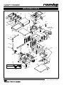
1
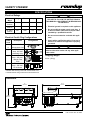
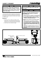
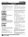
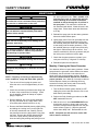
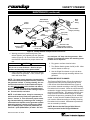
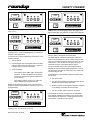
MANUFACTURING
NUMBERS:
9100700
9100710
9100720
C
L IS
T ED
US
AN
VARIETY STEAMER
I T A T IO
L IS
N
S
T ED
CM
Models VS-350
P/N 1010745 Rev. G 03/06
Owner ’s Manual
VARIETY STEAMER
TABLE OF CONTENTS
Owner Information .....................................................2
General ......................................................................2
Warranty Information .................................................2
Service/Technical Assistance ....................................3
Important Safety Information ....................................4
Electrical Cord & Plug Configurations .......................6
Shipping Weight ........................................................6
Electrical Ratings .......................................................6
Specifications .............................................................6
Dimensions ................................................................6
Model Designation .....................................................6
Installation...................................................................7
Unpacking ..................................................................7
Equipment Setup .......................................................7
Water Pressure Regulator Installation Instructions ...7
Drain ..........................................................................8
Electrical ....................................................................8
Steaming Guide ..........................................................9
Operation...................................................................10
Operator Controls ................................................... 10
Operating Instructions .............................................11
Programming ............................................................12
General Programming ............................................ 12
Factory Settings...................................................... 12
Programming the Unit ............................................ 12
Maintenance ..............................................................14
Daily Cleaning ........................................................ 14
Monthly: Cleaning the Steam Generator ................ 14
Checking and Cleaning the Water Strainer Monthly16
Technical Theory of Operation ............................... 18
Troubleshooting .......................................................19
Wiring Diagram .........................................................21
Replacement Parts ...................................................22
LIMITED WARRANTY ...............................Back Cover
OWNER INFORMATION
General
Warranty Information
The Variety Steamer produces steam using plain tap
water for quick heating and reconstituting of food items.
Simple push-button action delivers a fully adjustable
impulse of steam. Because the amount of steam is
consistent, it removes the guesswork and produces a
uniform finished product from one operator to the next.
Please read the full text of the Limited Warranty in this
manual.
If the unit arrives damaged, contact the carrier immediately and file a damage claim with them. Save all
packing materials when filing a claim. Freight damage
claims are the responsibility of the purchaser and are
not covered under warranty.
This manual provides the safety, installation and operating procedures for the Variety Steamer. We recommend that all information contained in this manual be
read prior to installing and operating the unit.
The warranty does not extend to:
• Damages caused in shipment or damage as
result of improper use.
Your Variety Steamer is manufactured from the finest
materials available and is assembled to Roundup’s
strict quality standards. This unit has been tested at
the factory to ensure dependable trouble-free operation.
• Installation of electrical service.
• Normal maintenance as outlined in this manual.
• Malfunction resulting from improper maintenance.
• Damage caused by abuse or careless handling.
• Damage from moisture into electrical
components
• Damage from tampering with, removal of, or
changing any preset control or safety device.
IMPORTANT! Keep these instructions for future reference. If the unit changes ownership,
be sure this manual accompanies the equipment.
2
P/N 1010745 Rev. G 03/06
VARIETY STEAMER
OWNER INFORMATION (continued)
Service/Technical Assistance
Refer to the service agency directory and fill in the
information below:
If you experience any problems with the installation
or operation of your unit, contact your local Roundup
Authorized Service Agency. They can be found in the
service agency directory packaged with the equipment.
Authorized Service Agency
Name:
Phone No.:
Fill in the information below and have it handy when
calling your authorized service agency for assistance.
The serial number is on the specification plate located
on the rear of the unit.
Address:
Use only genuine Roundup replacement parts in this
unit. Use of replacement parts other than those supplied by the manufacturer will void the warranty. Your
Authorized Service Agency has been factory trained
and has a complete supply of parts for this unit.
Purchased From:
Date of Purchase:
Model No.:
You may also contact the factory at 1-877-392-7854
or 630-784-1000 if you have trouble locating your local
authorized service agency.
Serial No.:
Mfg. No.:
IMPORTANT
A.J. Antunes & Co. reserves the right to change specifications and product design
without notice. Such revisions do not entitle the buyer to corresponding changes,
improvements, additions or replacements for previously purchased equipment.
P/N 1010745 Rev. G 03/06
3
VARIETY STEAMER
IMPORTANT SAFETY INFORMATION
Throughout this manual, you will find the following safety words and symbols that signify important safety issues with
regards to operating or maintaining your Variety Steamer.
WARNING
WARNING
GENERAL WARNING. Indicates information important to the proper operation of
the equipment. Failure to observe may
result in damage to the equipment and/or
severe bodily injury or death.
ELECTRICAL WARNING. Indicates information relating to possible shock hazard.
Failure to observe may result in damage
to the equipment and/or severe bodily
injury or death.
CAUTION
WARNING
GENERAL CAUTION. Indicates information important to the proper operation of
the equipment. Failure to observe may
result in damage to the equipment.
HOT SURFACE WARNING. Indicates
information important to the handling of
equipment and parts. Failure to observe
caution could result in personal injury.
The following warnings and cautions appear
throughout this manual and should be carefully
observed.
In addition to the warnings and cautions in this manual,
use the following guidelines for safe operation of the
unit.
• Turn the unit off, disconnect the power
source, and allow unit to cool down before
performing any service or maintenance on the
unit.
• Read all instructions before using equipment.
• For your safety, the equipment is furnished with
a properly grounded cord connector. Do not
attempt to defeat the grounded connector.
• The procedures in this chapter may include
the use of chemical products. These chemical products will be highlighted with bold
face letters followed by the abbreviated HCS
(Hazard Communication Standard). See
Hazard Communication Standard manual for
the appropriate Material Safety Data Sheets
(MSDS).
• Install or locate the equipment only for its intended use as described in this manual. Do not use
corrosive chemicals in this equipment.
• Do not operate this equipment if it has a damaged cord or plug, if it is not working properly, or
if it has been damaged or dropped.
• This equipment should be serviced by qualified
personnel only. Contact the nearest Authorized
Service Agency for adjustment or repair.
• The equipment should be grounded according to local electrical codes to prevent the
possibility of electrical shock. It requires a
grounded receptacle with separate electrical
lines, protected by fuses or circuit breaker of
the proper rating.
• Do not block or cover any openings on the unit.
• Do not immerse cord or plug in water.
• Keep cord away from heated surfaces.
• All electrical connections must be in accordance with local electrical codes and any
other applicable codes.
• Do not allow cord to hang over edge of table or
counter.
4
P/N 1010745 Rev. G 03/06
VARIETY STEAMER
IMPORTANT SAFETY INFORMATION (continued)
• WARNING ELECTRICAL SHOCK HAZARD.
FAILURE TO FOLLOW THESE INSTRUCTIONS
COULD RESULT IN SERIOUS INJURY OR
DEATH.
-
Electrical ground is required on this appliance.
-
Do not modify the power supply cord plug.
If it does not fit the outlet, have a proper
outlet installed by a qualified electrician.
-
Do not use an extension cord with this
appliance.
-
Check with a qualified electrician if you
are in doubt as to whether the appliance is
properly grounded.
• Do not clean this appliance with a water jet.
• Do not use a sanitizing solution or abrasive
materials. The use of these may cause damage to the stainless steel finish.
• To ensure proper steaming characteristics,
some calcium/mineral deposits must be present on the generator surface. If, during cleaning, the surface does become free of deposits,
add plain tap water to the surface and allow
it to boil off. This will ensure proper steaming characteristics by creating a thin layer of
calcium/mineral deposits on the surface.
• Chlorides or phosphates in cleansing agents
(e.g. bleach, sanitizers, degreasers, or detergents) could cause permanent damage to
stainless steel equipment. The damage is
usually in the form of discoloration, dulling
of metal surface finish, pits, voids, holes or
cracks. This damage is permanent and not
covered by warranty:
• If the supply cord is damaged, it must be
replaced by the manufacturer or its service
agent or a similarly qualified person.
• This equipment is to be installed to comply with the basic plumbing code of the
Building Officials and Code Administrators,
Inc. (BOCA) and the Food Service Sanitation
Manual of the Food and Drug Administration
(FDA).
The following tips are recommended for maintenance of your stainless steel equipment,
• Water pressure must not exceed 30 psi (2.1
kg/cm2 or 207 kPa). Higher water pressures
may cause poor performance, flooding. To
reduce water pressure, install a water pressure regulator and set water pressure to
20 -25 psi (1.4 - 1.7 kg/cm2 or 138 - 172 kPa).
P/N 1010745 Rev. G 03/06
5
-
Always use soft, damp cloth for cleaning,
rinse with clear water and wipe dry. When
required, always rub in direction of metal
polish lines.
-
Routine cleaning should be done daily
using soap, ammonia detergent and water.
-
Stains and spots should be sponged using
a vinegar solution as required.
-
Finger marks and smears should be
rubbed off using soap and water.
-
Hard water spots should be sponged using
a vinegar solution.
VARIETY STEAMER
SPECIFICATIONS
Electrical Ratings
WARNING
ELECTRICAL SHOCK HAZARD.
FAILURE TO FOLLOW THE INSTRUCTIONS IN
THIS MANUAL COULD RESULT IN SERIOUS INJURY OR DEATH.
Model and
Mfg #
Voltage
Watts
Amps
Hertz
VS-350CS
9100700
208 -240
5000-6693
24-27.9
50/60
VS-350HJ
9100710
230
5000
21.7
50/60
• Electrical ground is required on this appliance.
VS-350HC
9100720
230
3500
15.2
50/60
• Do not modify the power supply cord plug. If
it does not fit the outlet, have a proper outlet
installed by a qualified electrician.
• Do not use an extension cord with this appliance.
Electrical Cord & Plug Configurations
Commercial Cord
H
Harmonized Cord
**(H)C
CEE 7/7, 16
Amp., 250 VAC
(Assembly Only).
*(C)S
L6-30P, 30
Amp., 250 VAC.,
Straight Twist
Lock.
**(H)J
CAUTION
All electrical connections must be in accordance
with local electrical codes and any other applicable codes.
Shipping Weight
30
A
R
C
• Check with a qualified electrician if you are in
doubt as to whether the appliance is properly
grounded.
Configuration
63 lbs. (28 kg)
50V.
Description
.2
Letter
Code
R
IEC-309, 32
Amp., 250 VAC.,
Pin & Sleeve
* Indicates that the Plug comes with a Commercial Cord
** Indcates that the Plug comes with a Harmonized Cord
Dimensions
23 1/2"
(597 mm)
14"
(356 mm)
11 9/64"
(283 mm)
UP
DOWN
PROGRAM
SINGLE SHOT
6
P/N 1010745 Rev. G 03/06
VARIETY STEAMER
INSTALLATION
Unpacking
1. Remove unit and all packing materials from shipping carton.
2. The unit should contain the following:
• Owner’s Manual
• Authorized Service Agency Directory
• Petro Gel Tube
• Inlet Hose and Strainer Assembly
• Black Drain Tubing
NOTE: If any parts are missing or damaged, contact Antunes Technical Service IMMEDIATELY at
1-877-392-7854 or 630-784-1000.
Figure 1. Variety Steamer
CAUTION
This equipment is to be installed to comply with
the basic plumbing code of the Building Officials
and Code Administrators, Inc. (BOCA) and the
Food Service Sanitation Manual of the Food and
Drug Administration (FDA).
3. Remove all packing materials and protective coverings from the unit.
4. Remove and wash all removable parts in soap
and water. Rinse with clean hot water and allow
to air dry.
Water Pressure Regulator Installation
Instructions
NOTE: The steam generator surface (Figure 8) will
have a thin white coating of artificial lime deposits.
This coating is necessary for steaming characteristics and should not be removed. Refer to the
Maintenance section of this manual for more information.
1. Install the regulator assembly to the steamer as
shown in Figure 2 and 2A.
2. Open the shut off valve to allow water flow to the
Regulator. Ensure that the steamer pressure
regulator is set at 20-25 psi. If not, confirm that
incoming water pressure is above 25 psi and, if
so, adjust the regulator by pulling softly on the
knob and turning until the gauge reads desired
pressure. Push in the knob to lock.
5. Wipe all surfaces of the unit with a hot damp
cloth.
NOTE: Do not use a dripping wet cloth. Wring out
before use.
6. Re-install all removed parts.
NOTE: If the pressure was adjusted, the existing
pressure must be relieved in order to register the
new set pressure
Equipment Setup
GENERAL
3. Push the “white” plastic tip on each 1/4” elbow
Quick Disconnect (Figure 2 and 2A) and hold for
a few seconds to purge out air in the line and
allow water to flow freely into a bucket with a
steady stream.
When placing the unit into service, pay attention to
the safety guidelines listed in the Important Safety
Information section of this manual.
PLUMBING
4. Push each 1/4” elbow Quick Disconnect into the
rear of the steamer(s) until a “click” is heard.
Turn on the steamers and allow 20 minutes to
warm up. Cycle the units 3 times and check the
pressure regulator setting. If there is a change,
adjust it again to read 20-25 psi and then push
the knob in to lock. The unit is ready for use.
NOTE: Variety Steamer models are designed to
use cold tap water at 20-25 psi (1.4-1.7 kg/cm2 or
138-172 kPa).
Your VS-350 requires direct water hookup. An Inlet
Hose and Strainer assembly (Figure 2 and 2A) is
supplied with the unit. A water pressure regulator
(P/N 7000235 (Figure 2A) to feed 2 steamers or P/N
7000314 (Figure 2) to feed 1 steamer), must first be
installed.
P/N 1010745 Rev. G 03/06
7
VARIETY STEAMER
CAUTION
Water pressure must not exceed 30 psi (2.1 kg/
cm2 or 207 kPa). Higher water pressures may
cause poor performance or flooding. To reduce
water pressure, install a water pressure regulator,
and set water pressure to 20-25 psi (1.4-1.7 kg/
cm2 or 138-172 kPa).
CAUTION
All electrical connections must be in accordance
with local electrical codes and any other applicable codes.
WARNING
ELECTRICAL SHOCK HAZARD.
Drain
FAILURE TO FOLLOW THE INSTRUCTIONS IN
THIS MANUAL COULD RESULT IN SERIOUS
INJURY OR DEATH.
Connect the black drain tube (Figure 8) to the drip tray
by pressing the tub onto the drain pipe at the bottom of
the drip tray. Place the other end of the tube in a drain
or collection pan.
•
•
Electrical
•
1. Place the unit on a sturdy, level table or other
work surface. Be sure the Rocker Switch (Power
On/Off) is in the OFF position before proceeding.
•
2. Connect the unit to the power supply.
•
Electrical ground is required on this appliance.
Do not modify the power supply cord plug. If
it does not fit the outlet, have a proper outlet
installed by a qualified electrician.
Do not use an extension cord with this appliance.
The unit should be grounded according to
local electrical codes to prevent the possibility of electrical shock. It requires a grounded
receptacle with separate electrical lines, protected by fuses or circuit breaker of the proper
rating.
Check with a qualified electrician if you are in
doubt as to whether the appliance is properly
grounded.
Manifold/Regulator
Assembly
Tubing - 1/4" ID PVC (2)
#8 Bracket Screws (3)
Cold
Water
Flow
!WARNING
MISUSE OF PRODUCTMAY CAUSE
PERSONALINJURY.READ ASME
INSTALATION/OPERATING INTRUCT
MADE IN USA IMI
R91G-24K-NLN
Inlet Hose & Strainer Assy. (supplied)
INLET 150 PSIG MAX
Shut off valve (not supplied)
OUTLET 125 PSIGMAX
18
To
Steamers
Pressure
Adjustment
knob
Elbow, Quick Disconnect - 1/4" (3)
Inlet Water
Supply
Figure 2A. Connecting Dual Manifold Water Pressure Regulator (P/N 7000235)
8
P/N 1010745 Rev. G 03/06
VARIETY STEAMER
Cold
Water
Flow
Connect Quick
Disconnect
Insert Here
Flexible Nylon Braided
1/4 " I.D. Tubing (Not Supplied)
Shut Off Valve
(Not Supplied)
Elbow Quick
Disconnect
Worm
Clamp
Water Pressure Regulator
& Strainer Assy. (P/N 7000314) Shown
Inlet Hose & Strainer
Assy. (Supplied)
Figure 2. Connecting Single Water Pressure Regulator
STEAMING GUIDE
The Variety Steamer makes it possible to expand a menu with just one piece of equipment. The Variety Steamer
produces a super-heated dry steam. This steam penetrates the product until the product’s temperature matches the
steam temperature. The guide below is an approximation of the number of steam shots and the time required to cook
the food item. Steam times may vary based on the state and quanitity of the food product.
PRODUCT
DESCRIPTION
DIAL SETTING
TIME
PRODUCT
DESCRIPTION
DIAL SETTING
TIME
PreCooked
Items
VS-200
VS-350
Frozen Items
VS-200
VS-350
Spaghetti
3
25 seconds
Mixed
Vegetables
6
55 seconds
Rice
3
25 seconds
Spaghetti
6
55 seconds
Egg Noodles
3
25 seconds
Ravioli
12
1 minute, 55
seconds
Macaroni
3
25 seconds
Tortellini
12
1 minute, 55
seconds
Ravioli
6
55 seconds
Tortellini
6
55 seconds
Poached Eggs
18
2 minutes, 45
seconds
Roast Beef,
Sliced
2
15 seconds
Bread Products
1-2
5-15 seconds
Shrimp
4
35 seconds
Tortilla Shell
1
5 seconds
Other
Fresh Items
Shrimp
8
1 minute, 15
seconds
Broccoli
10
1 minute, 35
seconds
Products starting temperature is from a refrigerated state unless otherwise stated.
This is also based on a full 20 ounce basket or two individual 10 ounce baskets.
P/N 1010745 Rev. G 03/06
9
VARIETY STEAMER
OPERATION
Operator Controls
TIMED CYCLE
ROCKER SWITCH (POWER ON/OFF)
The desired timed steaming cycle (up to 99 minutes
and 59 seconds) is selected by pressing and releasing any of the four menu buttons (Figure 3). The main
Control Board applies power to the solenoid at regular
intervals for the duration of the displayed cycle time.
The display counts down to zero when the cycle is
complete, then reverts back to the original programmed
cycle time and the unit is ready for the next cycle.
When the Rocker Switch (Power On/OFF) is in the ON
position, the Control Board is activated. If the generator temperature is below the factory preset setpoint,
power is applied to the generator until the setpoint
temperature is reached. The generator is constantly
monitored and power is regulated to maintain the temperature setpoint.
IMPORTANT: Your steamer is factory programmed
for the following (on each of the 4 menu channels):
MENU BUTTONS
When any menu button is pressed and released,
power is supplied to the solenoid, the solenoid operates, and water sprays onto the heated steam generator surface. The water flashes immediately into live
steam to heat the product.
• Total Cycle Time = 10 seconds [00:10]
(Range: 1 second to 99 minutes and 59 seconds)
• Shot Interval Rate (RATE) = 5 seconds [00:05]
(Range: 1 second to 5 minutes and 59 seconds)
One of two operational modes can be used: Single
Shot or Timed Cycle
• Steam Shot Time (SHOT) = 0.70 second [00:70]
(Range: 0.10 second to 2.50 seconds)
SINGLE SHOT
This converts approximately 3/4 oz. (25 milliliters)
of water to steam every 5 seconds for a 10 second
steaming cycle. To change any of these settings refer
to the Programming section of this manual.
The Single Shot button (Figure 3) is pressed and
released to initiate a single shot. The Control Board
applies power to the solenoid and a single “shot” of
steam occurs.
Display Window
Program Button
Menu Channel Indicator Lights
Single Shot Button
1
UP
UP and DOWN
Arrow Buttons
DOWN
PROGRAM
2
3
4
SINGLE SHOT
Menu Channel Buttons
Rocker (Power On/Off) Switch
Lock Lever
Figure 3. Operator Controls
10
P/N 1010745 Rev. G 03/06
VARIETY STEAMER
UP & DOWN ARROW BUTTONS
ent settings until correct cycle for that product is
found.
The actual generator temperature can be viewed by
depressing the UP arrow button (Figure 3) at any time.
The arrow buttons are used with the other buttons to
program the unit (see the Programming section of this
manual for more information).
4. When the cycle is complete, remove and empty
the basket(s). At the end of the serving day or
shift, turn off the unit and allow it to cool before
performing the daily Cleaning procedures in the
Maintenance section of this manual.
LOCK LEVER
WARNING
To avoid injury, be careful when pulling basket
assembly out from unit. Be sure to allow steam
to escape before putting hands or face over the
steamer.
When in the full forward (towards operator) position,
the lock lever (Figure 8) secures the generator manifold
in position on top of the unit. Moving the lock lever to
the full rearward position unlocks the generator manifold, allowing it to be removed for cleaning or servicing.
NOTE: Do NOT force the lever into position.
Steaming Tips
HI-LIMIT RESET THERMOSTAT
Listed below are some samples of products that have
been tested in the Variety Steamer. Recommended
settings are listed following each product. Refer to
the Programming section of this manual to setup the
steamer for any of these items (results may vary).
If the generator overheats for any reason, the Hi-Limit
Thermostat opens (trips) and cuts off power to the
generator. This can be reset by turning the unit off,
unplug the power cord, and allow the unit to cool for 45
minutes. Remove the Main Housing Cover and press
the Hi-Limit’s red reset button (Figure 8). If the Hi-Limit
Thermostat requires continuous resetting, contact your
Authorized Service Agency
Experiment with your products and different steaming times–a little more or less steam could change the
appearance and/or flavor.
Pre-cooked pasta is easily reconstituted, and gives you
a hot product without the wetness of the normal “dip”
method. CYC = 00.20, RATE = 00.05, SHOT = 00.55
NOTE: Units manufactured on or before October
2002 have an externally resettable Hi-Limit. To
reset it, remove the black protective cap located
underneath the front of the unit and press the button fully. Reinstall the cap after resetting the unit.
If you serve melted cheese on sandwiches, steam is
the perfect way to melt cheese. CYC = 00.10, RATE =
00.05, SHOT = 00.40
Operating Instructions
A steamed bun (which takes about 10-15 seconds)
says “Hot Sandwich” to your customer. CYC = 00.10,
RATE = 00.05, SHOT = 00.70
1. Turn the unit on and allow it to preheat for approximately 30 minutes.
IMPORTANT: Do not push any of the menu buttons during warm-up. The word “LOW” flashes on
the display to indicate the unit is not up to operating temperature. When the cycle time is displayed,
the unit may be operated.
Vegetables, rice, and bread products can be reconstituted by steaming before serving which reduces waste.
CYC = 00.20, RATE = 00.05, SHOT = 00.55
Dinner rolls, muffins, even tortillas can be heated completely and held without drying out the product.
2. Remove baskets and place desired product into
baskets. Insert baskets into the steamer.
Use a low plate or pan when steaming to allow
full steam penetration and shorter cooking times.
Condensation inside the steamer is normal, but excess
moisture indicates too much water is being used. See
the Programming and Equipment Setup areas of this
manual.
3. Single Shot: Press and release the Single Shot
button and wait 10 seconds for the steam to penetrate the product.
Timed Cycle: Momentarily pressing any one of
the four channel buttons will begin a steaming
cycle. During the cycle, the display will count
down to zero ending with an audible tone to signal the completion of the cycle.
Heat meat and bread products apart from each other,
then combine in a sandwich. This will keep the meat
juices from soaking the bread. Finish off a special
meal with a steamed hand towel–hot without excessive
moisture.
NOTE: Experiment by steaming product at differP/N 1010745 Rev. G 03/06
11
VARIETY STEAMER
PROGRAMMING
SHOT (Steam Shot Time) is used to adjust the water
volume used during each solenoid operation (shot of
steam) (Figure 6).
Before starting initial programming, there are three
items that should be verified.
*
Check/change the setpoint temperature of the generator (it is recommended that the generator be set
at 375°F (191°C).
* Change the display from Fahrenheit (F) to Celsius
(C) or vice versa.
* Verify the generator temperature after a 30 minute
pre-heat time.
Listed below are the steps to follow for the recommendations listed above.
The amount of steam produced by your unit depends
on the amount of water sprayed onto the steam generator surface. Flooding of the generator may occur if the
SHOT setting is too high or if the RATE setting is too
low.
To prevent this from occurring, the RATE (Shot Interval
Time) should be increased to allow more time for generator heat recovery, and the SHOT (Steam Shot Time)
can be decreased to reduce the water volume.
15:00
UP
DOWN
PROGRAM
Adjustments should be made to both values to determine the optimum settings for your cooking needs.
Factory Settings
START/STOP
To verify the actual generator temperature, press and
hold the UP arrow button. The unit will display the
actual generator temperature.
The VS-350 is factory programmed for the following values for each of the 4 menu channels:
CYC = [00:10] 10 seconds
(Range: 1 second to 99 minutes 59 seconds)
400F
UP
DOWN
PROGRAM
RATE = [00:05] 5 seconds (recommended)
(Range: 1 second to 5 minutes 59 seconds)
SHOT = [00:70] 0.70 seconds (recommended)
(Range: 0.10 second to 2.50 seconds)
START/STOP
To verify or change the generator setpoint temperature, press and hold the UP and DOWN arrow buttons
simultaneously for three seconds. Then, raise or lower
the temperature by depressing the UP or DOWN arrow
buttons. Release the buttons when the desired temperature is reached.
These settings deliver approximately 3/4 oz. (25 milliliters) of water every 5 seconds for a 10 second cooking
time. Changes may be made to any of these settings.
However, for optimum performance, settings should
remain as shown above.
To restore the factory settings:
15:00
1. Turn the unit off. Press and hold the Program
and Single Shot buttons.
UP
DOWN
PROGRAM
START/STOP
2. Turn the unit on while still holding these buttons.
3. Release the buttons as soon as the unit stops
beeping.
To Change the display from Fahrenheit (F) to Celsius
(C), press and hold the UP arrow and the PROGRAM
buttons simultaneously for three seconds. Repeat the
process to reverse.
Programming the Unit
NOTE: CYC, RATE, and SHOT are sequential operations per channel for all programming (you must
perform all steps for CYC and RATE to change
SHOT).
General Programming
CYC (Total Cycle Time) refers to the total amount of
cooking time set for the product (Figure 4).
NOTE: CYC, RATE, and SHOT are only displayed
momentarily during the programming sequence
when the PROGRAM button is pressed.
RATE (Shot Interval Time) is the time set between
each shot of steam during a complete cycle (Figure 5).
12
P/N 1010745 Rev. G 03/06
VARIETY STEAMER
CYC (Total Cycle Time)
PROGRAMMING (continued)
CYC
1. Turn the Rocker Switch (power On/Off) to ON
(Figure 3). Allow 30 minutes to preheat the unit.
1
NOTE: During preheating, the display will flash
“LOW”. When unit reaches operating temperature,
the display shows the factory preprogrammed
(default) time in minutes/seconds (Figure 7) and the
active channel indicator light will be on.
DOWN
UP
2
3
4
SINGLE SHOT
Figure 4. CYC Mode on Menu 1
2. Press the Program button to change the control
from OPERATION to PROGRAM mode. CYC
will appear in the display for a moment. Select
a Menu Channel (1 thru 4), making the selected
channel the active channel.
RATE
1
DOWN
UP
NOTE: If no change is made withing 10 seconds
at any time during the programming process, all
changes made up to that point are stored in memory and the control reverts to OPERATION mode.
PROGRAM
2
3
4
SINGLE SHOT
Figure 5. RATE Mode on Menu 1
SHOT
3. Press the UP or DOWN arrow buttons to change
the total cycle time in minutes (Figure 7).
1
DOWN
UP
4. Press the PROGRAM button again, then use the
UP or DOWN arrow buttons to change the total
cycle time in seconds.
PROGRAM
2
3
4
SINGLE SHOT
Figure 6. SHOT Mode on Menu 1
Minutes
5. When finished, either:
a.) Press the selected menu channel button to
store the changes; pressing this again will start
the steam cycle.
OR
b.) Select another menu channel for change and
repeat steps 3 & 4. Changes made to previous
channels will automatically be stored.
Seconds
00:10
1
UP
DOWN
PROGRAM
2
3
4
SINGLE SHOT
Figure 7. Programming Mode SINGLE SHOT Button
Used for Saving All Changed Settings.
RATE (Shot Interval Time)
6. While in Program mode (press the PROGRAM
button if not in this mode), press both the UP and
DOWN arrow buttons simultaneously. RATE will
appear in the display for a moment (Figure 5).
10. Use the UP or DOWN arrow buttons to increase
or decrease the time.
11. Press the selected channel button to store the
changes (Figure 6) or press another channel button to store the changes and select a new channel.
7. Use the UP or DOWN arrow buttons to change
the RATE setting in seconds.
8. Press the PROGRAM button again, then use the
UP or DOWN arrow buttons to change the rate
time in minutes.
12. Repeat steps 1 - 11 for any of the other Menu
Channels.
NOTE: The SINGLE SHOT button may be pressed
at anytime during programming to store any changes made and execute a fixed single shot of 0.70
second.
SHOT (Steam Shot Time)
9. Press the PROGRAM button again and SHOT
will appear in the display for a moment (Figure 6).
P/N 1010745 Rev. G 03/06
PROGRAM
13
VARIETY STEAMER
MAINTENANCE
the steam generator hole. Take a suitable 1/16”
punching tool (such as a paperclip) and fully
insert it through all 18 orifices in the black
manifold as well as through the 10 orifices in
the spray tube. This assures the orifices are
not obstructed with debris. Wash all items in hot,
soapy water. Rinse these items and allow them
to air dry.
WARNING
Turn the unit off, disconnect the power source,
and allow the unit to cool down before performing
any service or maintenance on the unit.
WARNING
Refer to the instructions for cleaning and handling
the unit within the Important Safety Information
section of this manual.
5. Reinstall the spray tube into the steam generator
hole and reinstall diffuser plate.
CAUTION
Do not use a sanitizing solution or abrasive materials. The use of these may cause damage to the
stainless steel finish.
6. Lightly apply some Petrol Gel (included) onto the
large black O-ring and reinstall the O-ring onto
the manifold plate (this allows the manifold plate
to seat easily onto the steam generator). Hold
the manifold plate up to a light source and verify
that light is visible through all the orifices. If so,
seat the manifold fully onto the generator and pull
the locking lever forward to lock the plate.
CAUTION
If a chemical cleaner is used, be sure it is safe to
use on cast aluminum. Observe all precautions
and warnings on product label.
CAUTION
Unplug power cord before moving and servicing
this appliance.
7. Check that the water pressure regulator is correctly set to 20 PSI (1.4 Kg/cm2 or 138 kPa).
8. Reinstall all parts and accessories.
CAUTION
Failure to regularly and/or properly clean this
equipment may damage it or cause the user bodily injury.
Monthly: Cleaning the Steam Generator
Your steamer utilizes an open steam generator. Water
sprayed onto the generator surface flashes into steam
immediately, but the minerals in the water do not
steam, they stay on the generator surface. A small
amount of calcium/mineral deposits are needed for
proper operation, but a build-up of excessive calcium/
mineral deposits causes poor steaming efficiency,
excessive moisture (wet steam) and will eventually
affect the steaming action completely.
Daily Cleaning
NOTE: Frequency of cleaning is determined by
water conditions, usage and water filter systems.
1. Turn the unit off and unplug the power cord.
Allow the unit to cool for approximately 30 minutes.
1. Turn the Rocker Switch (power On/Off) to OFF.
Unplug the power cord and allow the unit to cool
down before proceeding.
2. Check the rear water quick disconnect fitting and
all hose clamp connections for leakage. If leakage is apparent, tighten all clamps or replace
part(s) if required.
2. Perform the Daily Cleaning procedures, but DO
NOT reassemble the unit.
3. Remove baskets, top cover housing assembly,
drip tray, and wash in hot, soapy water. Then,
rinse these parts and allow them to air dry.
3. With the unit cool, use a NON ABRASIVE brass
brush and/or scraper to loosen and remove the
excessive calcium/mineral deposits from the generator surface (Figure 8). Wipe the generator
with a clean damp cloth. Reassemble the unit.
4. Remove the Black Manifold plate by slightly lifting
and sliding the Locking lever (on the right side
of the unit) towards the rear, carefully remove
the plate and remove the large black O-ring from
the plate. Remove the diffuser plate and then
remove the spray tube by carefully lifting the
loose end and gently twisting and pulling it out of
NOTE: If deposits are still excessive and/or difficult to remove, see Step 4.
14
P/N 1010745 Rev. G 03/06
VARIETY STEAMER
MAINTENANCE (continued)
Drip Tray
Black
Drain
Tubing
Black Manifold
Plate (w/ orifices)
Double
Baskets
O-ring
(must be
lubricated
daily)
Top Cover assy.
Steam
Generator
Spray Tube
(w/ orifices)
Electrical
Housing
Cover
Inlet Hose Assy.
(w/ Strainer)
Pressure Relief
Plunger (assembly)
Diffuser
Lock
Lever
Older units came
equipped with an external
resettable Hi-Limit Thermostat
Hi-Limit Thermostat
(inside unit)
Figure 8. Variety Steamer Components & Accessories
4. Wearing protective eyewear and gloves, pour
delimer solution (not supplied) onto the generator
surface (Figure 8). Be sure to follow the delimer
manufacturer’s directions for proper mixture and
use.
ture and pour 1/4” deep into hot generator. After
mixture is converted to steam, the remaining loose
powder can be wiped off.
6. Plug power cord into electrical outlet
CAUTION
If a chemical cleaner/delimer is used, be sure it is
safe to use on cast aluminum. Observe all precautions and warnings on the product label.
7. Turn Rocker Switch (power On/Off) to ON. Allow
unit 30 minutes to warm up.
8. Use the Single Shot button to cycle unit three
separate times to purge remaining delimer from
generator.
5. Using a sponge or dry towel, remove the delimer
solution from the generator. Then, rinse the generator with clear water.
PRESSURE RELIEF PLUNGER
NOTE: To ensure proper steaming characteristics,
some calcium/mineral deposits must be present on
the generator surface. If, during cleaning, the surface does become free of calcium/mineral deposits, add plain tap water to the surface and allow it
to boil off. This may have to be repeated several
times in order to formulate a thin coating of deposits. If unsuccessful, see below.
The Pressure Relief Plunger (Figure 8) protects the
equipment and user from any harm that can result
if the orifices of the Black Manifold Plate (Figure 8)
has not been cleaned according to the Daily Cleaning
Procedures in this manual. When the orifices become
restricted or clogged, steam pressure buiilds up within
the black manifold plate. This pressure build-up eventually forces the Pressure Relief Plunger to elevate
and relieve the pressure, generating a loud “whistling”
sound. If at any time this condition should occur, the
unit must be cleaned according to the Daily Cleaning
Proceduers in this manual. Maintenance procedures
are not covered by warranty.
NOTE: In soft water areas, it may be necessary to
add a small amount of lime to the generator surface to “season” it. This will ensure proper steaming characteristics by producing a thin coating of
calcium/mineral deposits on the generator surface.
Seasoning mixture consists of 3/4 ounces (25ml/
25cc) of baking soda, 3/4 ounces (25ml/25cc) of
lime and 1 quart (950ml/950cc) of water. Stir mixP/N 1010745 Rev. G 03/06
NOTE: Be sure that the Plunger Relief Valve is
securely mounted to the Plunger Weldment.
15
VARIETY STEAMER
MAINTENANCE (continued)
Checking and Cleaning the Water Strainer
Monthly
GENERAL
2. Take the strainer cup and mesh strainer to the
sink and gently flush all the accumulated debris
out of them, be especially careful not to damage
the mesh strainer screen.
The Water Strainer protects the unit from any foreign
debris in the water line that could get into the food,
damage the unit’s solenoid (causing the unit to leak or
flood), or interfere with the equipment’s proper and consistent operation (Figure 10).
3. Carefully place the mesh strainer screen into its
seat at the bottom of the clear plastic cup and
confirm that the orange O-ring is properly seated
in its place before screwing the Strainer cup and
top back together.
To ensure proper and consistent steaming results,
visually check the water pressure regulator gauge and
strainer cup regularly. If the pressure on the gauge has
dropped, visually check the clear plastic strainer “cup”
and clean out the accumulated deris as follows.
4. Purge the air out of the strainer and tubing by
disconnecting the male quick disconnect fitting
from the equipment and, over a bucket, pushing
its “white” plastic tip in until there is a good water
flow.
1. Shut off the water supply valve to the unit,
unscrew the clear plastic strainer “cup” and carefully remove the mesh strainer screen.
5. Replace damaged or worn parts as needed.
Item
1/4
1
2
3
4
NPT
2
2
NOTE: Item 1 is made up of
shown items 2-4.
Part
No.
Description
7000333
2040130
7000334
2110104
Qty.
Water Line Strainer Kit
1
Male Adapter, barbed - 1/4”
2
Replacement Screen and O-ring Kit 1
Clamp, Worm (Not shown)
2
3
Figure 10. Water Line Strainer Kit
Diagnostics
*
The four-channel controller is also equipped with diagnostic features. Listed under each drawing is a brief
description of the particular feature. Also contained in
the control housing mounted on the control board are
diagnostic LED’s. They are in three colors and represent the following:
*
Green (Water): When lit, indicates that 24 VAC is
is being supplied to open the solenoid.
NOTE: This LED is only lit for approximately one
second.
HIGH
SHOT
Green (Program): When lit, indicates factory settings are being set.
1
UP
*
Yellow (Audio): When lit, indicates 10-15 VDC
is being supplied to the audio signal. The Audio
Signal will sound for 3 seconds.
*
Red (Heat): When lit, indicates the unit is calling
for heat by supplying 3-5 VDC to the solid state
relay. When off, it indicates the heating circuit is
satisfied.
DOWN
PROGRAM
2
3
4
SINGLE SHOT
HIGH will be displayed when the generator temperature exceeds the setpoint temperature by 50°F (10°C).
16
P/N 1010745 Rev. G 03/06
VARIETY STEAMER
LOW
SHOT
PWR
SHOT
1
DOWN
UP
PROGRAM
2
3
4
1
SINGLE SHOT
UP
LOW will be displayed until the generator temperature exceeds
250°F (121°C).
DOWN
UP
PROGRAM
2
3
1
SINGLE SHOT
ERR (Error) will be displayed if there is a programming
parameters error. If this message appears you will have to
clear the current parameters.
2. Push the Single Shot and Program buttons simultaneously and, while turning the unit back on, continue to
hold them until you hear the Beep Stop.
If the Display appears normal, try a single shot
before attempting to reprogram the unit.
3
4
2. Turn the unit back ON while pressing both the UP and
DOWN arrow buttons at the same time.
3. Read the highest control cabinet temperature recorded
on the display and release the arrow buttons.
4. Turn the unit OFF again to preserve this record.
1
2
3
To clear/reset this record, press both the UP and DOWN
arrow buttons simultaneously (before turning the unit OFF)
and the display will show 33°F - indicating that record has
been cleared - and then turn the unit OFF.
4
SINGLE SHOT
OPEN will be displayed when the thermocouple is “open” or not
installed correctly. The unit will not call for heat.
P/N 1010745 Rev. G 03/06
2
SINGLE SHOT
1. Turn the unit OFF.
OPEN
SHOT
PROGRAM
PROGRAM
To determine the control cabinet’s highest temerature since
the last reset:
Review the Programming section of this manual and then
program the Menu Channel Buttons according to your cooking requirements.
DOWN
DOWN
The Control Board monitors the control cabinet ambient
temperature and records the highest temperature. Your service technician could find such information very useful when
troubleshooting the unit.
3. Check the display:
•
4
The TEMP Display indicates that the control cabinet temperature has exeeded 155°F (68°C). If this occurs, the unit
must be turned off for at least 20 minutes so that it can cool
off and reset. If this condition occurs again, contact your
maintenance person or Authorized Service Agency.
1. Turn the unit off.
If the Display shows “ERR” again, repeat steps 1
through 2. If “ERR” still appears on the display,
contact your maintenance person or Authorized
Service Agency.
3
TEMP indicates the control cabinet temperature has exceeded 155°F (68°C) causing the unit to shut down.
To clear the unit’s current programming and reset the unit to
its factory settings:
•
2
SINGLE SHOT
TEMP
SHOT
4
UP
UP
PROGRAM
PWR (Power) will be displayed when the supply voltage is lower than 160 Volts AC or above 265 Volts AC.
ERR
1
DOWN
17
VARIETY STEAMER
MAINTENANCE (continued)
Technical Theory of Operation
Each of the four channel buttons can be custom programmed for cycle time, time between when each
steam shot occurs, and water volume used per each
shot (See the Programming section of this manual). An
audio signal will sound for three seconds at the end of
the cycle.
When the Rocker Switch (power On/Off) is ON, line
voltage flows to the primary side of the step down
transformer. The transformer’s secondary side supplies
12 and 24 VAC to the Control Board.
Once powered, and provided that the generator’s temperature is below the setpoint temperature, the Control
Board calls for heat by supplying 3 to 5 VDC to the
Solid State Relay terminals 3 (+) 4 (-). Once powered,
the Solid State Relay then closes terminals 1 and 2,
which allows line voltage to flow to the generator.
Two safety devices are incorporated into the VS-350:
•
Hi-Limit Thermostat
•
Pressure Relief Plunger
If the heating circuit continues to call for heat and the
generator overheats, a manual resettable Hi-Limit
Thermostat will trip and open the generator circuit.
As the generator begins to heat up, a type “K” thermocouple monitors the internal generator temperature. As
the heat continues to increase, so does the thermocouple’s DC millivolts.
If water and or steam pressure builds up beneath the
black Manifold Plate (due to restricted Manifold Plate
orifices), a Pressure Relief Plunger will elevate and vent
the steam pressure above the manifold plate.
Once the generator’s temperature approaches the setpoint temperature, the Control Board begins to pulse
the VDC to the Solid State Relay. The generator’s VAC
and AMPS will also pulse during this point. When the
generator’s temperature is between the recommended
setpoints of 375 - 400° F (190 - 204° C), the thermocouple generates approximately 7.5 - 8.5 DC millivolts.
The Control Board receives these millivolts and proceeds to remove the 3-5 VDC to the Solid State Relay
since the heating circuit has now become satisfied.
NOTE: If any of these conditions should arise, the
root cause must be determined and corrected. See
the Maintenance section of this manual for further
details.
NOTE: All direct water fed units require a Water
Pressure Regulator. It should be set to 20-25 psi
(1.4-1.7 kg/cm2 or 138-172 kPa). Failure to install a
Water Pressure Regulator will result in poor steaming and flooding of the steam generator.
Then, the Solid State Relay terminals 1 and 2 open up,
and the generator stops heating. The heating circuit
cycles on and off as needed, even at idle.
When the Single Shot button is pushed, it signals the
Control Board to initiate a single shot of steam. The
Control Board then supplies 24 VAC to the Solenoid
Valve for a split second. The Solenoid Valve opens and
allows approximately 3/4 - 1 ounce (4 to 5 tablespoons)
of water to be disbursed onto the generator surface
for steaming. The water is immediately converted into
steam, which is forced up through the black Manifold
Orifices to steam the product within the baskets.
18
P/N 1010745 Rev. G 03/06
VARIETY STEAMER
TROUBLESHOOTING
WARNING
To avoid possible personal injury and/or damage to the unit, inspection, test and repair of electrical equipment should be performed by qualified service personnel. The unit should be unplugged when servicing,
except when electrical tests are required.
Problem
Rocker Switch (power
On/Off) is turned on but
the Switch Indicator Light
is still off and the Control
Panel is blank
Possible Cause
Corrective Action
Power Cord not correctly plugged in.
Plug in the power cord correctly.
The power cord and/or electrical plug
is damaged.
Inspect electrical wire, plug, and receptacle.
The main electrical panel circuit breaker is off or has been tripped.
Reset circuit breaker. Contact your maintenance person or Authorized Service Agency if
it trips again.
Rocker Switch is inoperable.
Contact your maintenance person or
Authorized Service Agency for service.
The unit’s main electrical panel circuit breaker
trips.
Damaged receptacle, plug, or cord; a
loose connection or an internal component failure.
Turn the unit off, allow it to cool to room temperature, and then restart the unit.
Power On/Off switch and
indicator are on but the
display is blank.
Control Board is inoperable.
Contact your maintenance person or
Authorized Service Agency for service.
Power On/Off switch is
turned on, the switch
indicator light is on, the
control panel display is
on, but the unit is not
heating up.
Heat Relay is inoperable.
Transformer is inoperable.
Loose or burnt wiring in heating circuit.
Hi-Limit Thermostat is tripped.
Thermocouple is inoperable.
Control Board is inoperable.
Steam Generator is inoperable.
Reset the Hi-Limit Thermostat according to
the Operations section of this manual. If the
Hi-Limit Thermostat requries continuous resetting, contact your maintenance person or
Authorized Service Agency for service.
Loose or burnt wiring in heating circuit.
Unit heats but there is lit- Water Line Valve is closed.
tle or no steam produced Filter Strainer is restricted.
Check that the Water Line Valve is open.
Check and clean the Filter Strainer as
described in the Maintenance section of this
manual.
and/or
The product requires
more steaming than
usual.
P/N 1010745 Rev. G 03/06
Quick Disconnect is not fully engaged
at rear of the unit or is damaged.
Remove and reengage the Quick Disconnect
firmly until a “click” is heard. Replace if damaged.
Low or no water pressure in water line.
Remove the Quick Disconnect Insert from the
rear of the unit. While holding into an empty
cup, press the white plastic tip. Strong steady
water flow should be noted. If so, re-engage
firmly into unit. If not present, or pressure
is low, contact your maintenance person or
plumber.
Spray Tube is restricted.
Remove and clean Spray Tube as described
in the Maintenance section of this manual.
Black Manifold orifices are restricted.
Remove and clean the Black Manifold as
described in the Maintenance section of this
manual.
Unit is not being cleaned daily or properly.
Clean unit daily as described in the
Maintenance section of this manual.
19
VARIETY STEAMER
TROUBLESHOOTING (continued)
Problem
Unit heats but there is little or no
steam produced
and/or
The product requires more
steaming than usual (continued).
Prossible Cause
Corrective Action
Improper water pressure to unit.
Verify that a water pressure regulator is
installed and set to 20 - 25 psi.
Insufficient or excessive calcium/
mineral buildup on Generator surface.
Verify that a thin layer of deposits is
present on the Generator surface.
Refer to the Maintenance section of this
manual.
Channels, or Rate and Shot values
were programmed improperly.
Restore programming to original values
as described in the Programming section of this manual and then reprogram
as needed.
Black Manifold O-ring is damaged or
missing.
Install Manifold O-ring if missing.
Replace if it is damaged.
Low Generator setpoint temperature. Verify the setpoint temperature is 375° F
(190° C) to 400° F (204° C).
Steam leaks out of the sides of
the black Manifold Plate.
Black Manifold O-ring is damaged or
missing.
Install Manifold O-ring if missing.
Replace if it is damaged.
Black Manifold is difficult to lock
and unlock onto the generator
with the sliding lever.
Black Manifold not being removed
and cleaned daily as required.
Remove and clean the Black Manifold
daily as described in the Maintenance
section of this manual.
Black Manifold O-Ring is damaged
or worn.
Replace Black Manifold O-Ring if damaged or worn.
Black Manifold O-ring is not being
lubricated daily with Petro gel.
Lubricate the Black Manifold O-ring daily
as described in the Maintenance section
of this manual.
Generator is dirty.
Clean or delime the Generator. See the
Maintenance section of this manual for
more information.
Unit floods overnight and/or con- Solenoid valve is being held open by
tinues to steam even when in idle debris from the building’s water line
mode.
piping due to no pre-strainer/filter on
the water line just before the unit.
Attempt to flush the debris out of the
valve by rapidly operating the unit on a
number of “Single Shot” cycles and then
letting the unit rest. If the unit still leaks,
contact your maintenance person or
Authorized Service Agency.
Unit is whistling during use.
See the Maintenance section of this
manual.
Unit is not being cleaned Daily and/
or properly.
20
P/N 1010745 Rev. G 03/06
VARIETY STEAMER
WIRING DIAGRAM
POWER
CORD
# 18 GA. AWM-105°C
GRN
GRN-YEL
WHT/BLU
BLK/BRN
NOTE: ALL WIRES TO BE 10 GA. TFE-200°C
UNLESS OTHERWISE SPECIFIED.
TERMINAL
BLOCK
RED
GND
GRN
HEATER
S.S. RELAY
WHT
BLK
BLK
WHT
WHT
HI-LIMIT
THERMOSTAT
2
3+
1
4-
YEL
T4 T3
T2
T1
T11
CONTROL
BOARD
THERMOCOUPLE
5
230V
#
4
2
BLK
4
2
1
8
6
#
#
1
10
ORG
BLUE
#
BLK
BLK
P/N 1010745 Rev. G 03/06
21
BLK
BLK
BRN
RED
GRN
ORG
SWITCH
BOARD
BRN
#
#
POWER
SWITCH
SOLENOID
TRANSFORMER
5
#
WHT
YEL
T5 T6 T7 T8 T9 T10
VARIETY STEAMER
REPLACEMENT PARTS
41
41
1
66
2
4
6
43
67
3
42
38
40
39
43
17
37
18
5
8
23
Available with
L6-30P or CEE 7/7
59
16
58
62
19
8
12
36
45
63
64
46
44
13
7
64
34
15
20
14
61
33
21
65
51
52
55 9
22
50
47
53
54
10
29
18
48
27
24
25
17
35
32
28
11
26
49
68
22
P/N 1010745 Rev. G 03/06
VARIETY STEAMER
REPLACEMENT PARTS (continued)
Item
Part
No.
1
2
3
4
5
0011539
7000404
0200187
0020947
7000293
7000295
7000375
6
7
8
9
10
11
12
13
14
15
16
17
18
19
2020104
7000297
0501139
0021040
2100138
0021038
2190102
2000214
4040145
200K127
208K106
7000139
0010584
0700479
0700453
0700588
20
21
22
23
24
25
7000403
4050232
4010192
0503776
1001058
0011370
26
27
28
29
30
31
32
33
34
2100109
4010137
0020946
7000319
0700591
2140116
0021244
7000294
7000344
Description
Top Housing Assy. (Jumbo)
Generator Manifold (incl. #66 & 67)
O-Ring
Drip Tray Assy.
Generator, (208V) 5000w
Generator, (230V) 5000w
Generator (230V) 3500w
(for MFG # 9100720 only)
Drain Tube
Insulation
Retainer, Generator
Channel, Lock Lever Support
Ball Knob
Lever Support
Teflon Tube
Tube SS 1/4”
Solenoid
Inlet Tube Kit
Quick Disconnect Body
Quick Disconnect Insert
Inlet Hose Assy. (incl. #17 & 68)
Power Cord (L6-30P)
Mfg. No. 9100700
Power Cord (CEE 7/7 plug)
Mfg. No. 9100720
Power Cord (IEC-309 plug)
Mfg. No. 9100710)
Solid State Relay Kit (Incl. #21)
Heat Sink
Board, Switch PC
Cover, Main Housing
Label, Control Panel
2” Leg
(Incl. No. 26)
Rubber Foot, Leg
Rocker Switch, Power On/Off
Panel, Bottom
Transformer, 115/230V-24V
Wire Set (not shown)
Petrol Gel (not shown)
Control Panel
Control Board
Hi-limit Thermostat Kit
P/N 1010745 Rev. G 03/06
Item
Qty.
Part
No.
Description
**(See NOTE below)
Front Leg Spacer
Main Housing
Spray Tube
Diffuser
Handle
Handle Guard, Black
Basket
Bolt, Square Neck,3/8-16 x 3/4” SS
Large Basket Assy. (Jumbo)
(Incl. 39, 40, 41 & 42)
44 406K006
Terminal Block, 3-Pole
45 0400315
Strain Relief
46 308P143* Nut, Hex, KEPS, #8-32
47 304P105* Nut, Hex, KEPS, #4-20, Zinc
48 310P120* Screw, Machine, #10-32 x 5/8”
49 308P103* Screw, Machine, #8-32 x 1/4”
50 0021039
Lock Lever Weldment
51 325P169
Bolt, Shoulder, 5/16 x 1/2”
52 212P120
Spacer, .437” O.D. x .340 I.D.
53 325P154
Washer, Helical Spring Lock, 1/4”
54 325P102
Nut, Hex, 1/4-20
55 212P118
Washer, Flat, SS
58 325P109* Bolt, Hex Hd., 1/4-20 x 1/2”
59 325P104* Washer, Flat, 1/4”
61 4050214
Type “K” Thermocouple
62 1001053
Cleaning Label
63 204P114* Female Elbow 1/4” Tube
64 2040126
Nut & Sleeve Assy. 1/4”
65 0011071
Lock Lever Assy.
(Incl. 9, 50, 51, 52, 53, 54, & 55)
66 2170115
Plunger Valve
67 0021474
Plunger Weldment
68 See page 16 for Strainer Parts identification.
* Only available in packages of 10.
1
1
1
1
1
35
36
37
38
39
40
41
42
43
1
1
2
1
1
1
1
1
1
1
1
1
1
1
1
1
1
1
1
4
1
4
1
1
1
1
1
1
1
1
2120171
0021041
0020958
0502669
2100119
2100240
0503851
338P102
0011502
Qty.
2
1
1
1
2
2
2
2
2
1
1
1
1
1
1
1
1
1
1
1
1
1
1
1
1
2
1
1
1
1
** NOTE: VS-350 units manufactured with serial
numbers 0210XXXX and prior were manufactured with an external manual resettable capillary
bulb Hi-Limit Thermostat. If this type of Hi-Limit
Thermostat should require replacement, it must be
replaced with a bi-metal type (P/N 7000344) and
retrofitted into unit.
23
LIMITED WARRANTY
Equipment manufactured by Roundup Food Equipment Division of A.J. Antunes & Co. has been constructed of the finest materials available and manufactured to high quality standards. These units are
warranted to be free from mechanical and electrical defects for a period of one year from date of purchase or 18 months from shipment from factory, whichever occurs first, under normal use and service,
and when installed in accordance with manufacturer’s recommendations.
To insure continued proper operation of the units, follow the maintenance procedure outlined in the
Owner’s Manual.
1.This warranty does not cover cost of installation, defects caused by improper storage or handling prior to
placing of the Equipment. This warranty does not include overtime charges or work done by unauthorized
service agencies or personnel. This warranty does not cover normal maintenance, calibration, or regular
adjustments as specified in operating and maintenance instructions of this manual, and/or labor involved
in moving adjacent objects to gain access to the Equipment. This warranty does not cover consumable
items such as gaskets, O-rings, and light bulbs. Nor does it cover water contaminant problems such as
foreign material in water lines or inside solenoid valves. It does not cover water pressure problems or
failures resulting from improper/incorrect voltage supply. This warranty does not pay travel, mileage,
or any other charges for an authorized service agency to reach the equipment location.
2.Roundup reserves the right to make changes in design or add any improvements on any product. The
right is always reserved to modify equipment because of factors beyond our control and government regulations. Changes to update equipment do not constitute a warranty charge.
3.If shipment is damaged in transit, the purchaser should make a claim directly upon the carrier. Careful
inspection should be made of the shipment as soon as it arrives and visible damage should be noted
upon the carrier’s receipt. Damage should be reported to the carrier. This damage is not covered under
this warranty.
4.Warranty charges do not include freight or foreign, excise, municipal or other sales or use taxes. All such
freight and taxes are the responsibility of the purchaser.
5.THIS WARRANTY IS EXCLUSIVE AND IS IN LIEU OF ALL OTHER WARRANTIES, EXPRESSED OR
IMPLIED, INCLUDING ANY IMPLIED WARRANTY OR MERCHANTABILITY OR FITNESS FOR A PARTICULAR PURPOSE, EACH OF WHICH IS HEREBY EXPRESSLY DISCLAIMED. THE REMEDIES
DESCRIBED ABOVE ARE EXCLUSIVE AND IN NO EVENT SHALL ROUNDUP BE LIABLE FOR SPECIAL CONSEQUENTIAL OR INCIDENTAL DAMAGES FOR THE BREACH OR DELAY IN PERFORMANCE OF THIS WARRANTY.
A.J. Antunes & Co.
Headquarters/Manufacturing
180 Kehoe Boulevard
Carol Stream, Illinois 60188 USA
Phone (630) 784-1000
Toll Free (800) 253-2991
Fax: (630) 784-1650
Antunes Equipment
Manufacturing (Suzhou) Ltd.,
9 Hou Ju Road, Building #24,
S&T Park, SND
Suzhou, Jiangsu, China 215011
Phone: 86-512-6841-3637
Fax: 86-512-6841-3907
www.ajantunes.com